Embed Size (px)
Citation preview

Foundation EngineeringCE 483
5. Settlement of shallow foundations
Copy right reserved to Dr O. Hamza
CONTENTS
– Introduction– Vertical stress increase in a soil mass ..caused by foundation load
– Elastic settlement calculation– Consolidation settlement calculation– Field test (Bearing capacity with .Settlement consideration)
– References
CE 483 - Foundation Engineering - 5. Settlement of shallow foundations 2

Introduction
CE 483 - Foundation Engineering - 5. Settlement of shallow foundations 3
Principal criteria for foundation design Types of settlements Things required to calculate settlements
Copy
righ
t res
erve
d to
Dr O
. Ham
za

CE 483 - Foundation Engineering - 5. Settlement of shallow foundations 4
When designing foundations, two principal criteria must be satisfied:
1. Maintaining Stability 2. Limiting Settlement
Stability against Bearing failure
Introduction
Principal criteria for foundation design

5
When designing foundations, two principal criteria must be satisfied:
1. Maintaining Stability 2. Limiting Settlement
Embankment and building constructed on soft ground (highly comprisable soil)
Soft ground
Crack
Introduction
Principal criteria for foundation design

Introduction
Principal criteria for foundation design
CE 483 - Foundation Engineering - 5. Settlement of shallow foundations 6
Therefore, the allowable bearing capacity qall should be the smaller of the following two:
The safe pressure that does not cause bearing failure
The safe pressure that does not cause unacceptable settlement
You learned how to calculate this (see previous chapter)
You will learn (in this chapter) how to estimate settlement

Introduction
Types of settlements
CE 483 - Foundation Engineering - 5. Settlement of shallow foundations 7
From structural consideration there are two types of settlements:
• Uniform settlement • Differential settlement
should be within the acceptable limit - given in the building code

Introduction
Types of settlements
8
From geotechnical consideration, there are two types of settlements:
Time, t
Settlement, S
End of Construction
Immediate (or elastic) settlement, (mostly during construction time)
Consolidation settlement (occurs over long period of time)
• Primary consolidation,• Secondary consolidation,

Introduction
Types of settlements
9
So, the total soil settlement ST may be contain one or more of these types:
Immediate settlement
elastic deformation with no change in water content
occurs rapidly during the application of load
occurs in sandy, silty and clayey soils

Introduction
Types of settlements
10
The total settlement of a foundation can then be given as:
ST = Se + Sc + Ss
What information do we need to know to calculate these settlements?
Introduction
Things required to calculate settlements
11
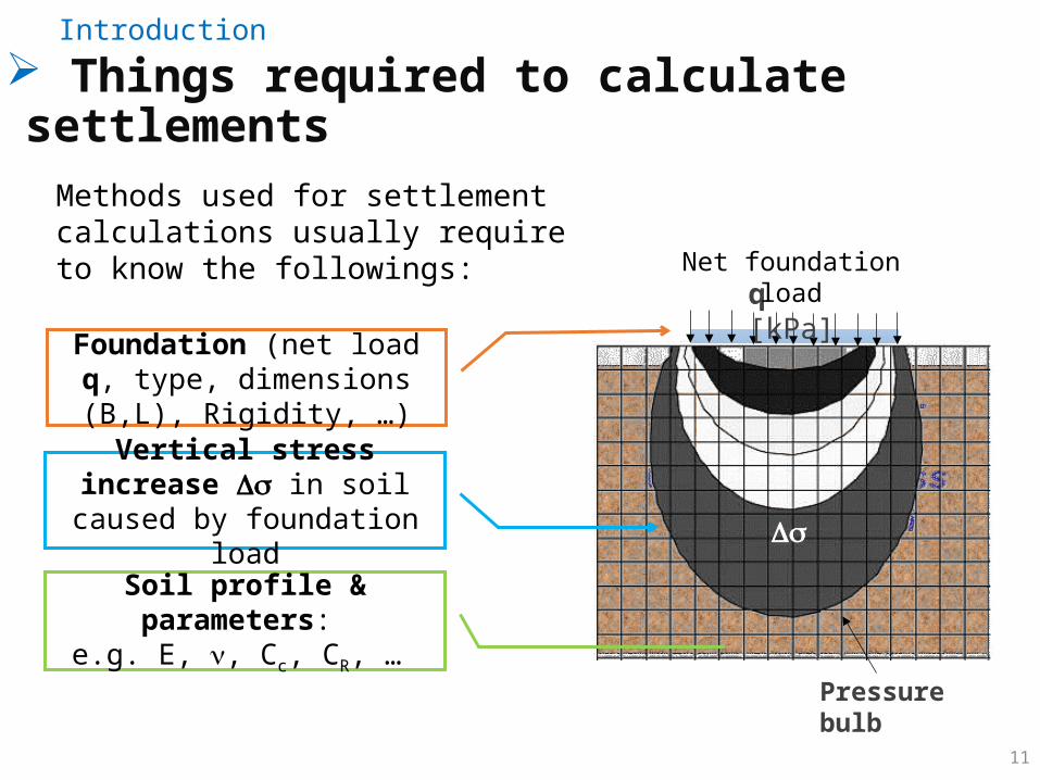
Methods used for settlement calculations usually require to know the followings:
q [kPa]
Pressure bulb
Vertical stress increase Ds in soil caused by foundation load
Soil profile & parameters: e.g. E, n, Cc, CR, …
Net foundation load
Ds
Foundation (net load q, type, dimensions (B,L), Rigidity, …)
Vertical stress increase in a soil mass caused by foundation load
CE 483 - Foundation Engineering - 5. Settlement of shallow foundations 12
Pressure bulb Stress due to a concentrated load Stress due to a circularly loaded area Stress due to vertical line load Stress below rectangular area Average vertical stress increases in a layer Approximate method

13
Pressure bulbVertical stress increase in a soil mass caused by foundation load
• Structure built on ground causes increase in vertical stress (pressure) in the soil below. q [kPa]
Pressure bulb
Net foundation load
Ds
• This pressure increase is distributed to the soil in the form of a pressure bulb (or pressure isobars).
• The stresses Ds of the pressure bulb is determined by elastic theory.

14
Pressure bulbVertical stress increase in a soil mass caused by foundation load
2B
2bB
q= 100 kPa q= 100 kPa
0.1 q
0.2 q
Ds=
• The size and shape of the pressure bulbs depend on the size and shape of the loaded area e.g. point load, circular or rectangular loaded area, …et.
Pressure bulbs under largeand small round foundations

15
Pressure bulbVertical stress increase in a soil mass caused by foundation load
Comparison between Pressure Bulb for square
and strip footings
16
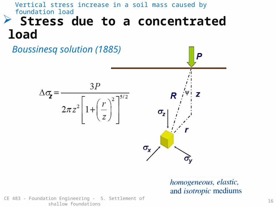
Stress due to a concentrated load
CE 483 - Foundation Engineering - 5. Settlement of shallow foundations
Vertical stress increase in a soil mass caused by foundation load
z
Boussinesq solution (1885)
17
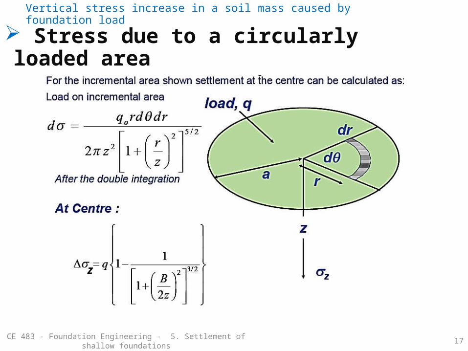
Stress due to a circularly loaded area
CE 483 - Foundation Engineering - 5. Settlement of shallow foundations
Vertical stress increase in a soil mass caused by foundation load
z

18
Stress due to vertical line load
CE 483 - Foundation Engineering - 5. Settlement of shallow foundations
Vertical stress increase in a soil mass caused by foundation load
z
19
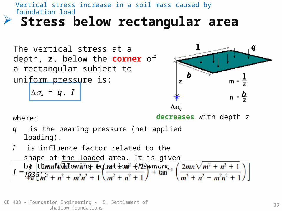
Stress below rectangular area
CE 483 - Foundation Engineering - 5. Settlement of shallow foundations
Vertical stress increase in a soil mass caused by foundation load
I
The vertical stress at a depth, z, below the corner of a rectangular subject to uniform pressure is:
Dsv
decreases with depth z
b
l
b
l
q
where:
q is the bearing pressure (net applied loading).
I is influence factor related to the shape of the loaded area. It is given by the following equation (Newmark, 1935):
Dsv = q. I

20
Stress below rectangular areaVertical stress increase in a soil mass caused by foundation load
m
n =
0.1
I

21
Stress below rectangular areaVertical stress increase in a soil mass caused by foundation load
To work out the vertical stress increase below the center of foundation, use:
l = ½ L b = ½ B
Dsv = 4 q. I
where: L: foundation lengthB: foundation width
DsvDsv
b
l
b
l
L
B
22
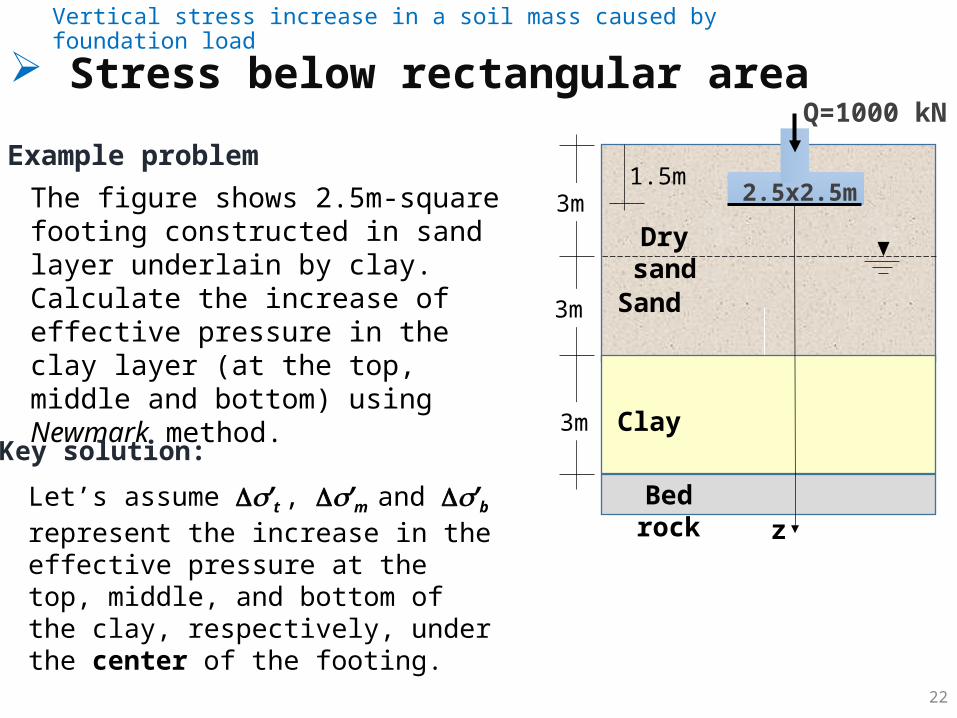
Stress below rectangular areaVertical stress increase in a soil mass caused by foundation load
The figure shows 2.5m-square footing constructed in sand layer underlain by clay. Calculate the increase of effective pressure in the clay layer (at the top, middle and bottom) using Newmark method.
Q=1000 kN
Example problem2.5x2.5m
Bed rock
Dry sand
Sand
3m
3m
3m
1.5m
ClayKey solution:
zLet’s assume ’t , ’m and ’b represent the increase in the effective pressure at the top, middle, and bottom of the clay, respectively, under the center of the footing.
23
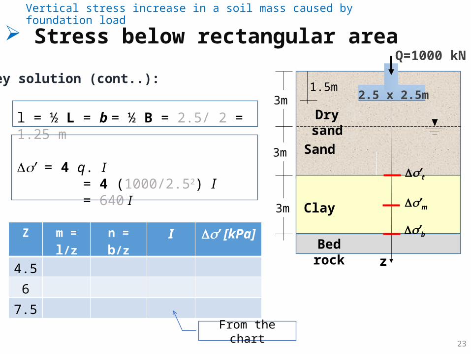
Stress below rectangular areaVertical stress increase in a soil mass caused by foundation load
Q=1000 kN
2.5 x 2.5m
Bed rock
Dry sand
Sand
3m
3m
3m
1.5m
Clay
Key solution (cont..):
z
l = ½ L = b = ½ B = 2.5/ 2 = 1.25 m
Ds’ = 4 q. I = 4 (1000/2.52) I = 640 I
Z m = l/z n = b/z I Ds’ [kPa]
4.5
6
7.5
’t
’m
’b
From the chart
24
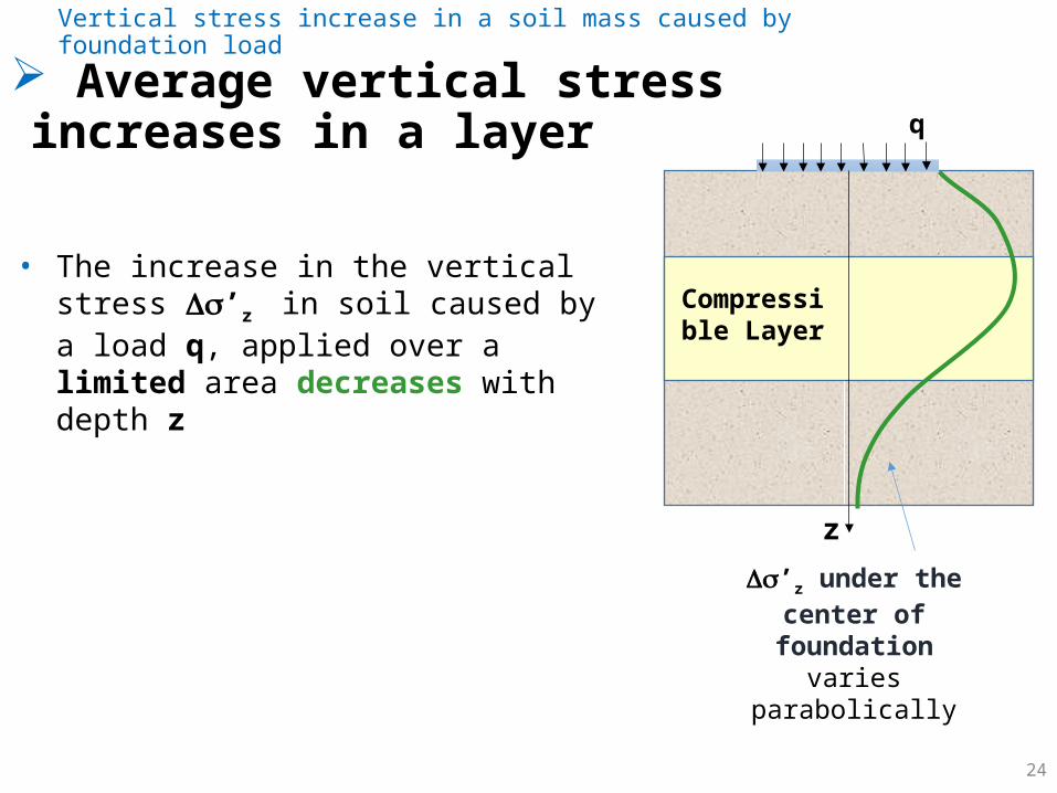
Average vertical stress increases in a layerVertical stress increase in a soil mass caused by foundation load
• The increase in the vertical stress ’z in soil caused by a load q, applied over a limited area decreases with depth z
z
Compressible Layer
’z under the center of foundation varies
parabolically
q
25
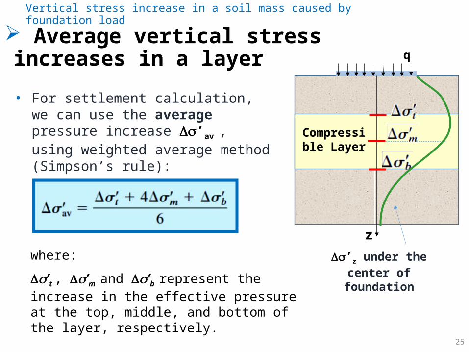
Average vertical stress increases in a layerVertical stress increase in a soil mass caused by foundation load
• For settlement calculation, we can use the average pressure increase ’av , using weighted average method (Simpson’s rule):
z
where:
’t , ’m and ’b represent the increase in the effective pressure at the top, middle, and bottom of the layer, respectively.
Compressible Layer
’z under the center of foundation
q

26
Approximate methodsVertical stress increase in a soil mass caused by foundation load
GL
soil
q kPa
For wide uniformly distributed load, such as for vey wide embankment fill, the stress increase at any depth, z, can be given as:
z = q z
zdoes not decreases with depth z

27
Approximate methodsVertical stress increase in a soil mass caused by foundation load
For other cases, the vertical stress at any depth, z, can be calculated using 2:1 linear distribution method.
Z
2:1 method of finding stress increase under a foundation
q
2 vertical to 1 horizontal
2 vertical to 1 horizontal
B + Z
B

decr
ease
with
dep
th z
28
Approximate methodsVertical stress increase in a soil mass caused by foundation load
Z
ZZ
29
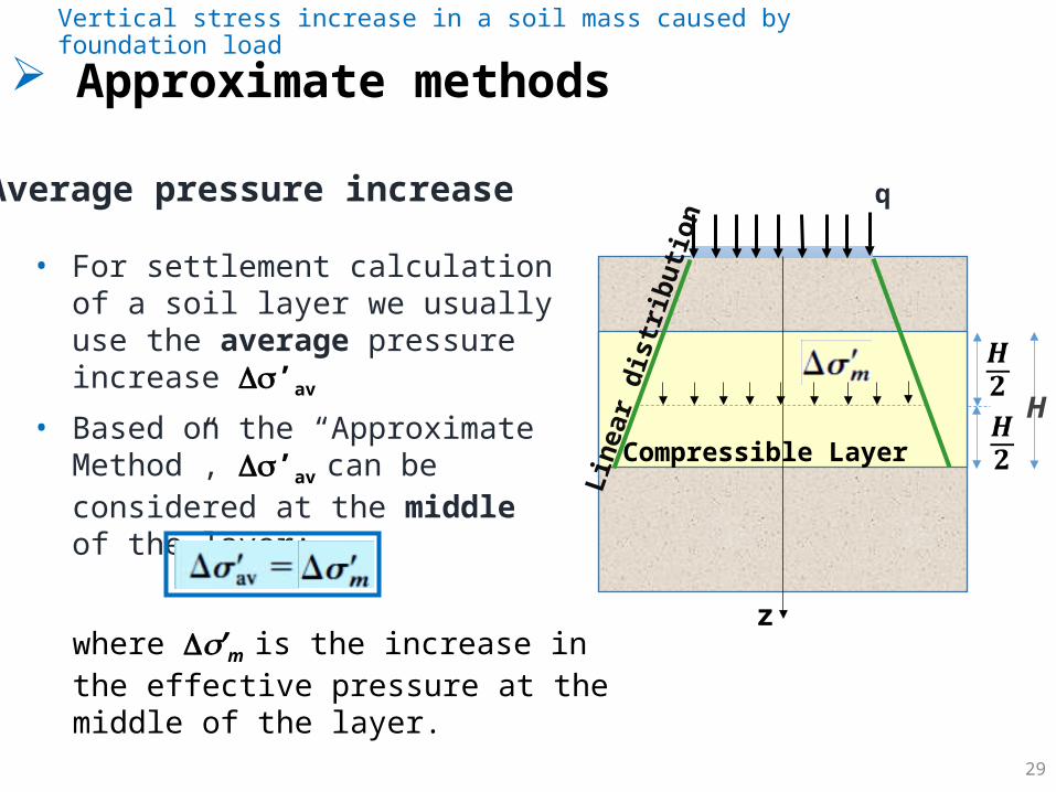
Approximate methodsVertical stress increase in a soil mass caused by foundation load
• For settlement calculation of a soil layer we usually use the average pressure increase ’av
• Based on the “Approximate Method”, ’av can be considered at the middle of the layer:
where ’m is the increase in the effective pressure at the middle of the layer.
Average pressure increase
z
Compressible Layer
H Li
near
dist
ributi
on
q
30
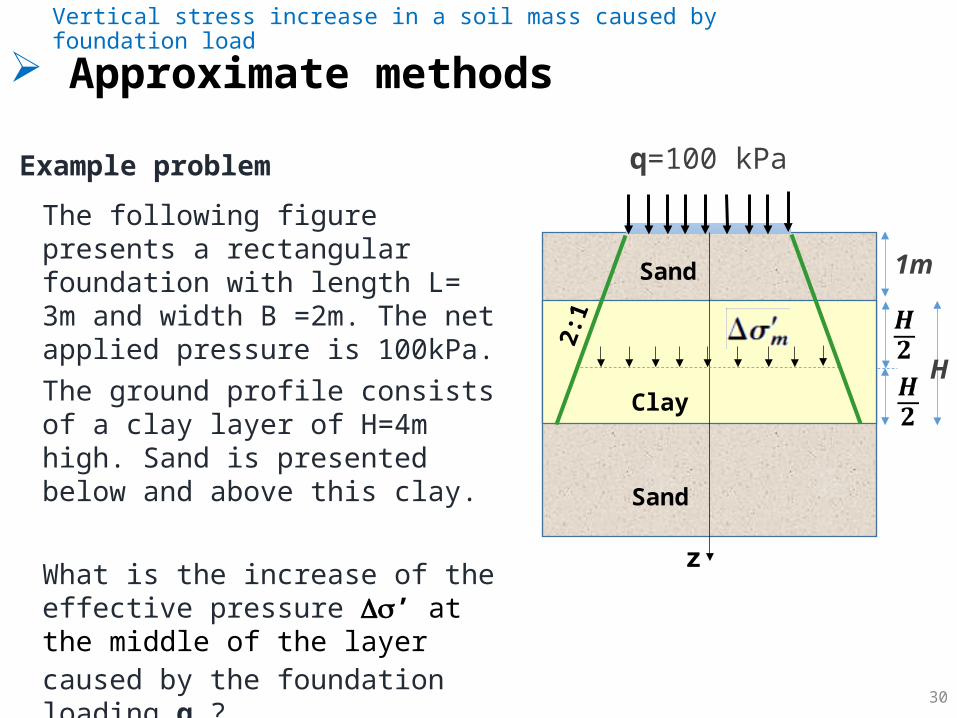
Approximate methodsVertical stress increase in a soil mass caused by foundation load
The following figure presents a rectangular foundation with length L= 3m and width B =2m. The net applied pressure is 100kPa.The ground profile consists of a clay layer of H=4m high. Sand is presented below and above this clay.
What is the increase of the effective pressure ’ at the middle of the layer
caused by the foundation loading q ?(use the approximate method)
Example problem q=100 kPa
z
Clay
Sand
Sand
2:1
1m
H
31
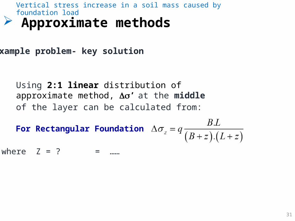
Approximate methodsVertical stress increase in a soil mass caused by foundation load
Using 2:1 linear distribution of approximate method, ’
at the middle of the layer can be calculated from:
Example problem- key solution
For Rectangular Foundation
where Z = ? = ……
Elastic settlement calculation
CE 483 - Foundation Engineering - 5. Settlement of shallow foundations 32
Contact Pressure and Settlement Profile Settlement based on general theory of Elasticity Elastic Settlement of saturated clayElastic Settlement of sandy soil: use of
strain .influence factor
33
Contact Pressure and Settlement ProfileElastic settlement calculation
CE 481 - Geotechnical Engineering II - 2. Compressibility of Soil 33
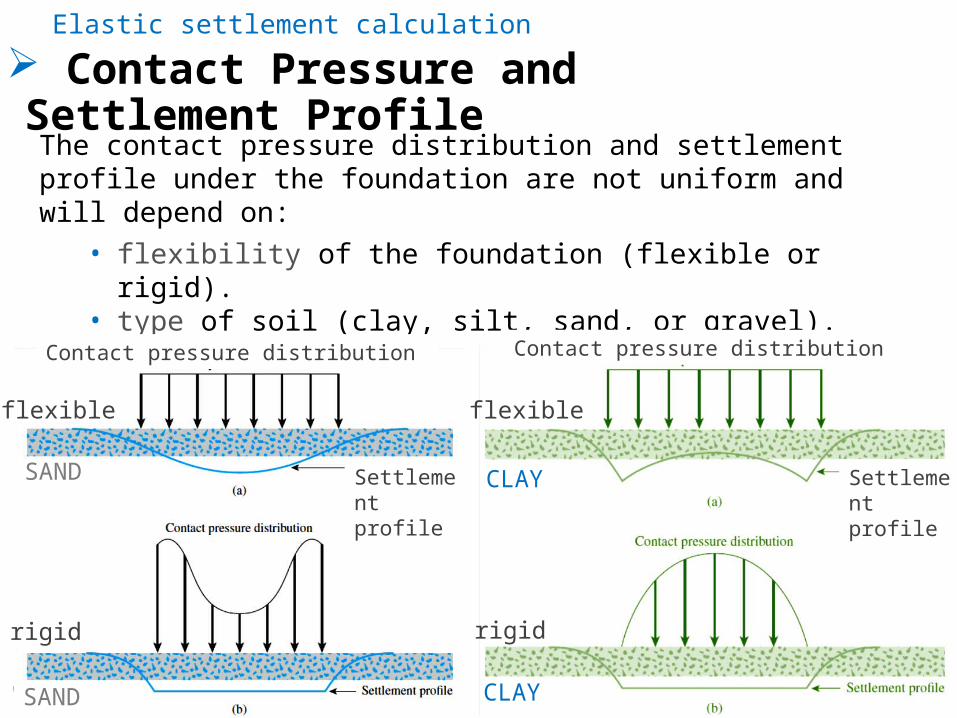
The contact pressure distribution and settlement profile under the foundation are not uniform and will depend on:
• flexibility of the foundation (flexible or rigid).• type of soil (clay, silt, sand, or gravel).
flexible flexible
rigid rigid
SAND
CLAY
CLAY
SAND
Contact pressure distribution Contact pressure distribution
Settlement profile
Settlement profile

34
Settlement based on theory of ElasticityElastic settlement calculation
Settlement Se =integration of vertical strain ez
CE 483 - Foundation Engineering - 5. Settlement of shallow foundations
35
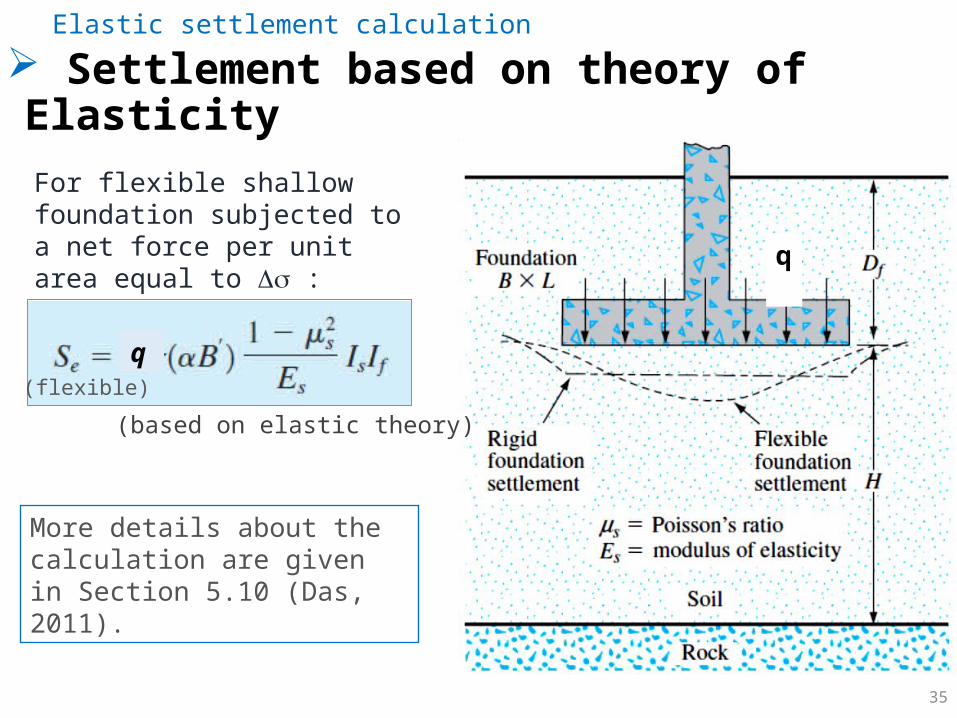
Settlement based on theory of ElasticityElastic settlement calculation
For flexible shallow foundation subjected to a net force per unit area equal to Ds :
rigid
(based on elastic theory)
q (flexible)
More details about the calculation are given in Section 5.10 (Das, 2011).
q
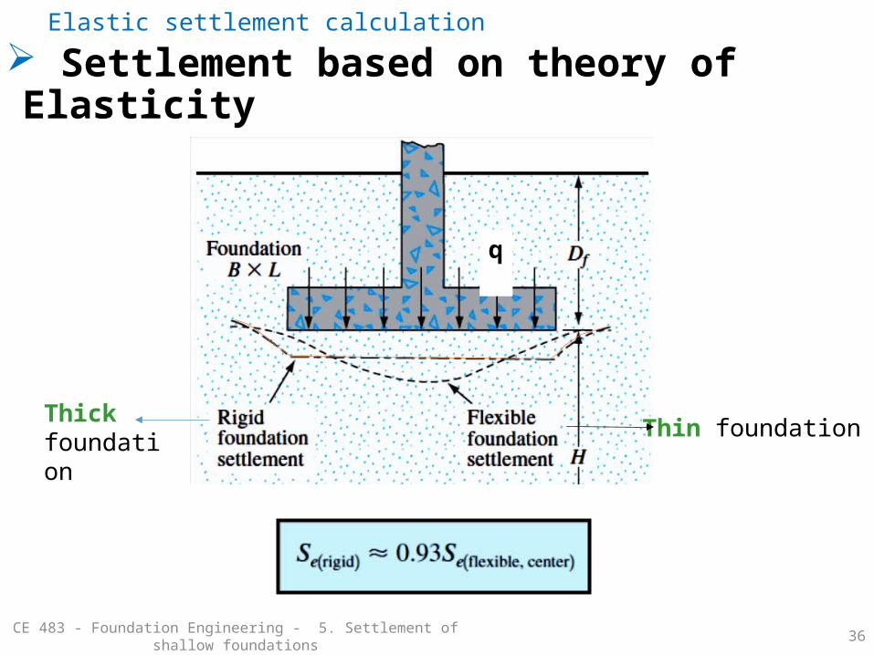
36
Settlement based on theory of ElasticityElastic settlement calculation
Thick foundation Thin foundation
q
CE 483 - Foundation Engineering - 5. Settlement of shallow foundations
37
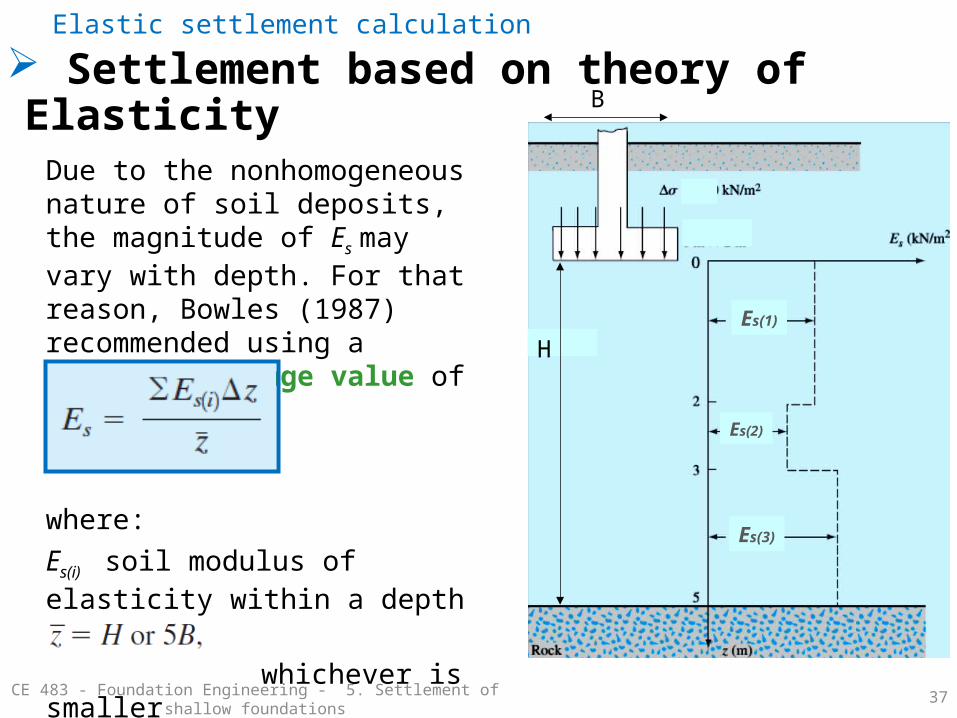
Settlement based on theory of ElasticityElastic settlement calculation
Due to the nonhomogeneous nature of soil deposits, the magnitude of Es may vary with depth. For that reason, Bowles (1987) recommended using a weighted average value of Es.
where:Es(i) soil modulus of elasticity within a depth Dz. whichever is smaller
Es(1)
Es(2)
Es(3)
H
B
CE 483 - Foundation Engineering - 5. Settlement of shallow foundations

38
Elastic Settlement of saturated clayElastic settlement calculation
Section 5.9 (Das, 2011)

39
Elastic Settlement of saturated clayElastic settlement calculation

40
Elastic Settlement of sandy soil: use of strain influence factor
Elastic settlement calculation
(applied by the foundation)
(changes with depth)
(changes with depth)
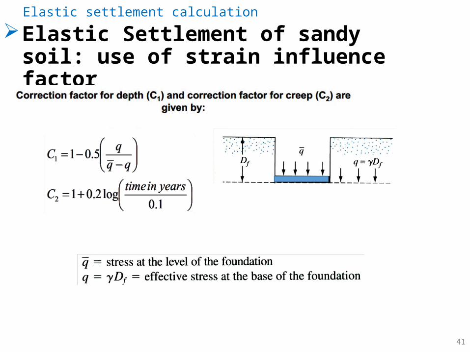
41
Elastic Settlement of sandy soil: use of strain influence factor
Elastic settlement calculation

42
Elastic Settlement of sandy soil: use of strain influence factor
Elastic settlement calculation
is obtained from CPT test
qc
qcE
by interpolation we can find:
1 ≤ L/B ≤10
How about if there is no CPT date available?
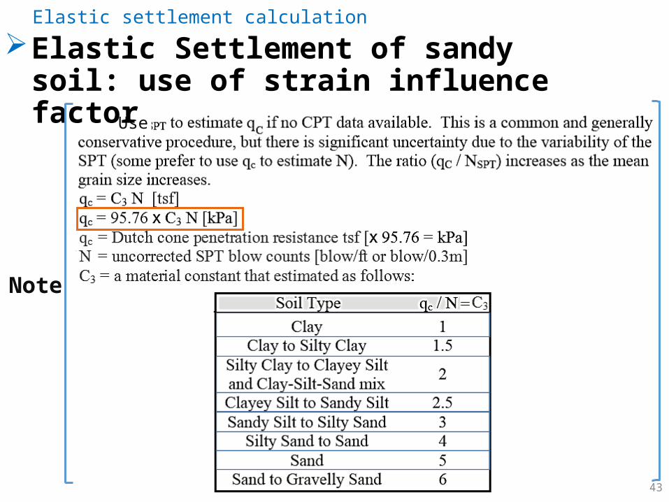
Note
Use
43
Elastic Settlement of sandy soil: use of strain influence factor
Elastic settlement calculation
44
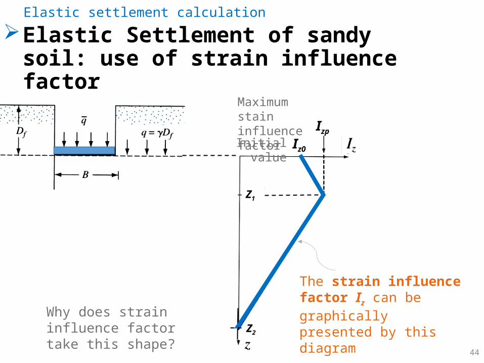
Elastic Settlement of sandy soil: use of strain influence factor
Elastic settlement calculation
The strain influence factor Iz can be graphically presented by this diagram
Iz0
Izp
Z1
Z2
Why does strain influence factor take this shape?
Maximum stain influence factor
Initial value
45
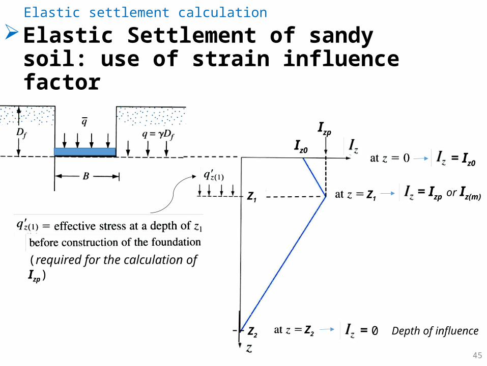
Elastic Settlement of sandy soil: use of strain influence factor
Elastic settlement calculation
Iz0
Izp
Z1
Z2
= Iz0
Z1
Z2
= Izp or Iz(m)
= 0 Depth of influence
(required for the calculation of Izp)

46
Elastic Settlement of sandy soil: use of strain influence factor
Elastic settlement calculation
Iz0
Izp
Z1
Z2Variables
Iz diagram varies with L/B
L
47
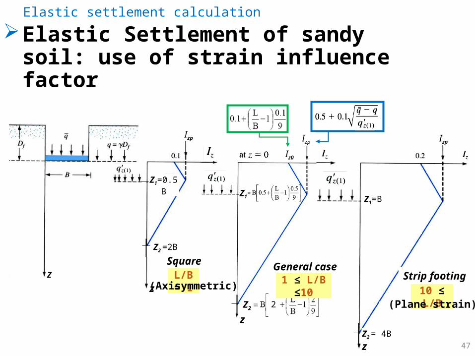
Elastic Settlement of sandy soil: use of strain influence factor
Elastic settlement calculation
zZ
Izp Izp Izp
z
z
Z2 =2B
Z2 =
Z2 = 4B
Z1=B
Z1=0.5B
Z1
2
Iz0
10 ≤ L/B
General caseSquareStrip footingL/B = 1 1 ≤ L/B ≤10(Axisymmetric)
(Plane strain)

48
Elastic Settlement of sandy soil: use of strain influence factor
Elastic settlement calculation
Z
* Calculated by interpolation between Case 1 and Case 3
Z2
Z1
Table summary of Iz profile
Z2
Z1
Z0

49
Elastic settlement calculation
Z2
Z1
50
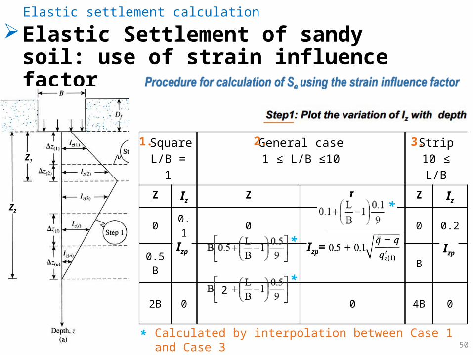
Elastic Settlement of sandy soil: use of strain influence factor
Elastic settlement calculation
SquareL/B = 1
General case1 ≤ L/B ≤10
Strip10 ≤ L/B
Z IzZ Iz
Z Iz
0 0.1 0 0 0.2
0.5B B
2B 0 0 4B 02
Izp=Izp Izp
*
*
*
* Calculated by interpolation between Case 1 and Case 3
1. 2. 3.
Z2
Z1

51
Elastic Settlement of sandy soil: use of strain influence factor
Elastic settlement calculation
Z2
Z1

52
In preparation for settlement calculation using strain influence method, the
soil is divided to smaller layers. Explain why the soil
is divided to 10 layers?
Class example
53
Elastic Settlement of sandy soil: use of strain influence factor
Elastic settlement calculation
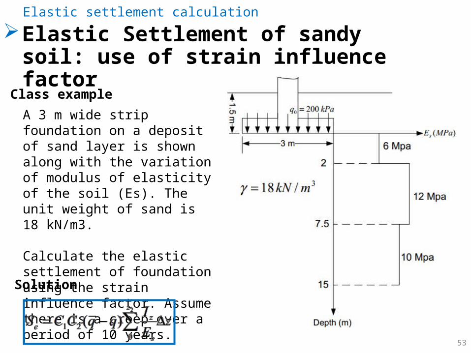
A 3 m wide strip foundation on a deposit of sand layer is shown along with the variation of modulus of elasticity of the soil (Es). The unit weight of sand is 18 kN/m3.
Calculate the elastic settlement of foundation using the strain influence factor. Assume there is a creep over a period of 10 years.
Class example
Solution
54
Elastic Settlement of sandy soil: use of strain influence factor
Elastic settlement calculation
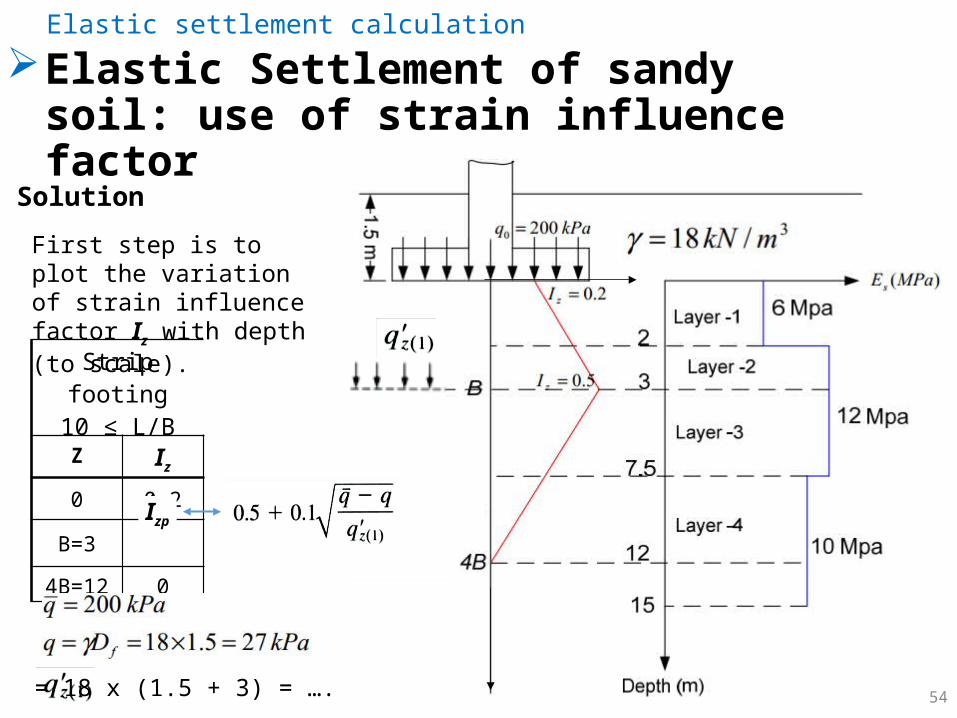
Solution
First step is to plot the variation of strain influence factor Iz with depth (to scale).
Strip footing10 ≤ L/B
Z Iz
0 0.2
B=3
4B=12 0
Izp
= 18 x (1.5 + 3) = ….
55
Elastic Settlement of sandy soil: use of strain influence factor
Elastic settlement calculation
Solution (cont..)
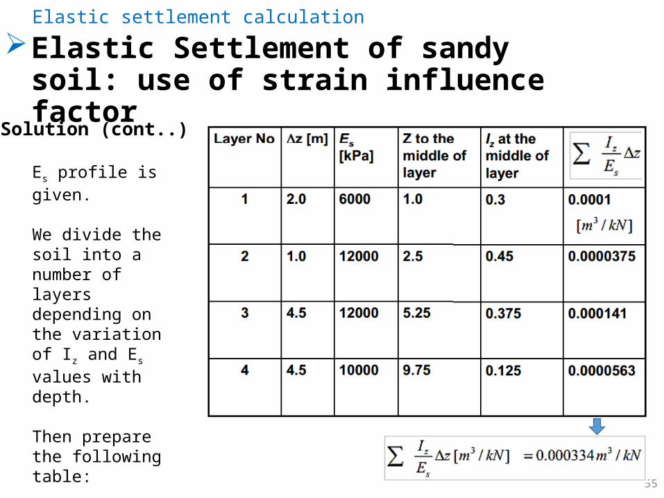
Es profile is given.
We divide the soil into a number of layers depending on the variation of Iz and Es values with depth.
Then prepare the following table:
56
Elastic Settlement of sandy soil: use of strain influence factor
Elastic settlement calculation
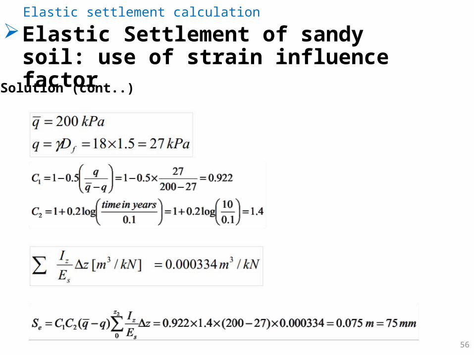
Solution (cont..)
57
Elastic Settlement of sandy soil: use of strain influence factor
Elastic settlement calculation
More examples are given in Das’s text book – Section 5.12

Consolidation settlement calculation
CE 483 - Foundation Engineering - 5. Settlement of shallow foundations 58
Basic consolidation process Laboratory Consolidation Test Soil compressibility parameters Normally Consolidated and Overconsolidated Clays Calculation of Primary Consolidation Settlement Secondary Consolidation Settlement

59
Basic consolidation processConsolidation settlement calculation
When a saturated soil is loaded,
saturated soil
GL
• in coarse soils (sand & gravel) the settlement takes place instantaneously. How can this be explained?
• in fine soils (clay & silt): settlement takes far much more time to complete. Why?
Time (months or years)
Sett
lem
ent
coarse soils
Fine soils
CE 483 - Foundation Engineering - 5. Settlement of shallow foundations
60
Basic consolidation processConsolidation settlement calculation
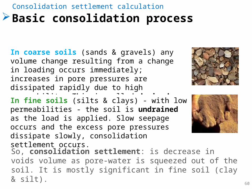
In coarse soils (sands & gravels) any volume change resulting from a change in loading occurs immediately; increases in pore pressures are dissipated rapidly due to high permeability. This is called drained loading.
In fine soils (silts & clays) - with low permeabilities - the soil is undrained as the load is applied. Slow seepage occurs and the excess pore pressures dissipate slowly, consolidation settlement occurs.
So, consolidation settlement: is decrease in voids volume as pore-water is squeezed out of the soil. It is mostly significant in fine soil (clay & silt).
61
Consolidation settlement calculation
Laboratory Consolidation Test
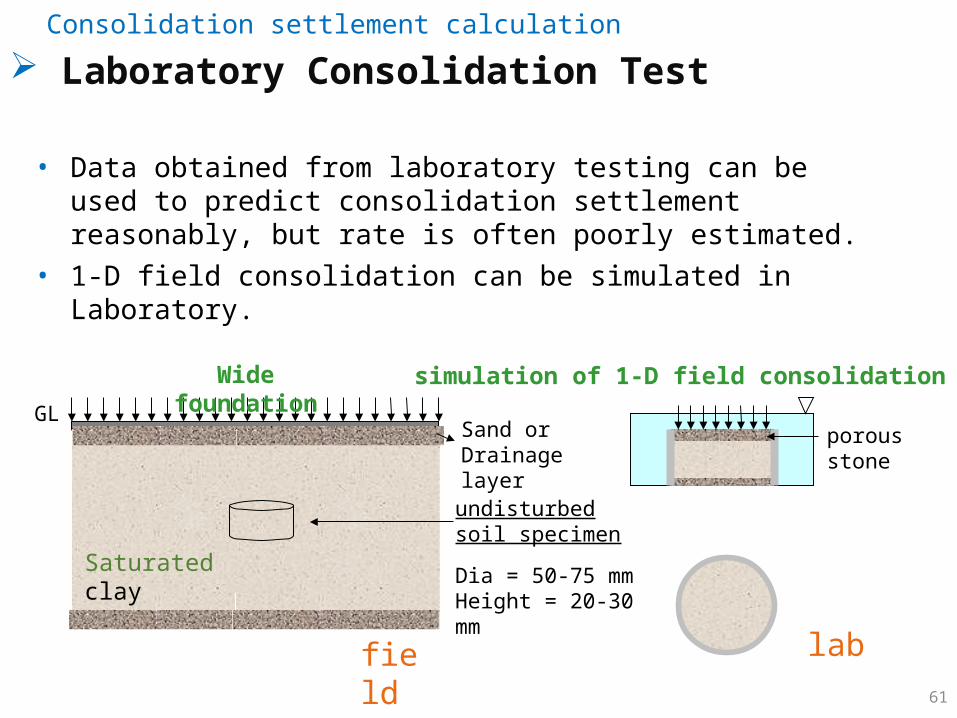
• Data obtained from laboratory testing can be used to predict consolidation settlement reasonably, but rate is often poorly estimated.
• 1-D field consolidation can be simulated in Laboratory.
field
GL
lab
undisturbed soil specimen
Dia = 50-75 mmHeight = 20-30 mm
porous stone
Wide foundation simulation of 1-D field consolidation in Lab
Saturated clay
Sand or Drainage layer
62
Consolidation settlement calculation
Laboratory Consolidation Test
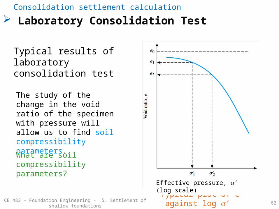
Typical plot of e against log s’
Effective pressure, s’ (log scale)
Typical results of laboratory consolidation test
The study of the change in the void ratio of the specimen with pressure will allow us to find soil compressibility parameters.
What are soil compressibility parameters?
CE 483 - Foundation Engineering - 5. Settlement of shallow foundations
63
Consolidation settlement calculation
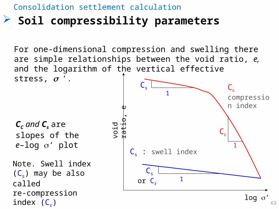
Soil compressibility parameters
log ’
void
rati
o,
e
1
Cc
Cc compression index
Cs : swell index
1
1Cs
For one-dimensional compression and swelling there are simple relationships between the void ratio, e, and the logarithm of the vertical effective stress, s ‘.
Cs
CC and Cs are slopes of the e–log s‘ plot
Note. Swell index (Cs) may be also called re-compression index (Cr)
or Cr
64
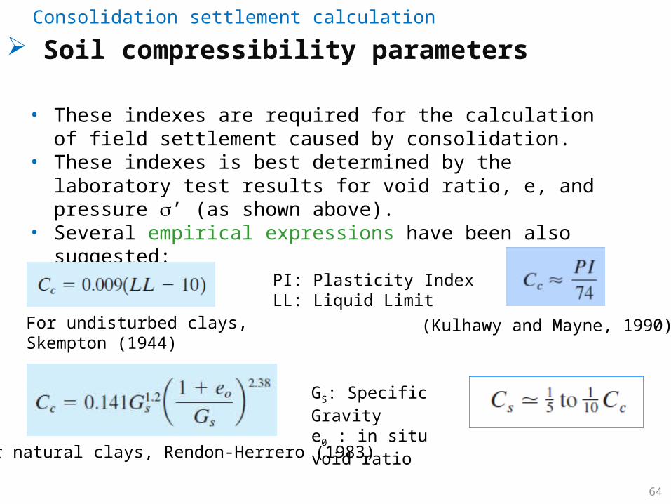
• These indexes are required for the calculation of field settlement caused by consolidation.
• These indexes is best determined by the laboratory test results for void ratio, e, and pressure s’ (as shown above).
• Several empirical expressions have been also suggested:
For undisturbed clays, Skempton (1944)
For natural clays, Rendon-Herrero (1983)
(Kulhawy and Mayne, 1990)
PI: Plasticity IndexLL: Liquid Limit
GS: Specific Gravitye0 : in situ void ratio
Consolidation settlement calculation
Soil compressibility parameters

65
Compression and Swell Indexes of some Natural Soils
Consolidation settlement calculation
Soil compressibility parameters
CE 483 - Foundation Engineering - 5. Settlement of shallow foundations
66
Void
ratio
, e
Effective pressure, s’ (log scale)
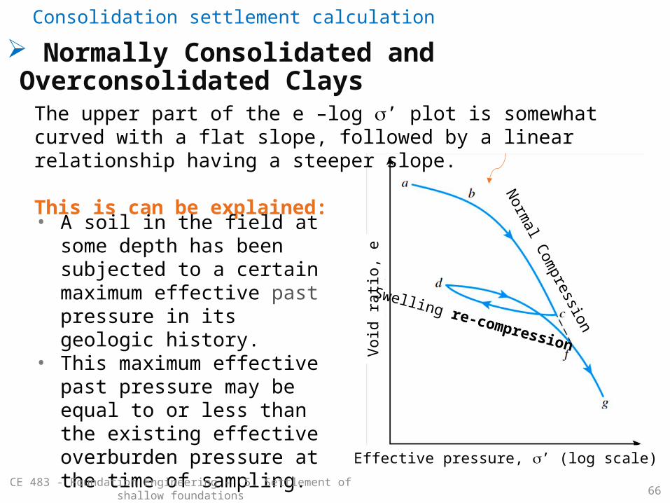
The upper part of the e –log s’ plot is somewhat curved with a flat slope, followed by a linear relationship having a steeper slope.
This is can be explained:
• A soil in the field at some depth has been subjected to a certain maximum effective past pressure in its geologic history.
• This maximum effective past pressure may be equal to or less than the existing effective overburden pressure at the time of sampling.
Normal Com
pression
Swelling re-compression
Normally Consolidated and Overconsolidated ClaysConsolidation settlement calculation
CE 483 - Foundation Engineering - 5. Settlement of shallow foundations

67
Void
ratio
, e
s’c
Effective pressure, s’ (log scale)
Casagrande (1936) suggested a simple graphic construction to determine the preconsolidation pressure s’c from the laboratory e–log s‘ plot.
In general the overconsolidation ratio (OCR) for a soil can be defined as:
where s ’ is the present effective vertical pressure.
Normally Consolidated and Overconsolidated ClaysConsolidation settlement calculation
If OCR > 1 overconsolidated soilIf OCR = 1 normally consolidated
68
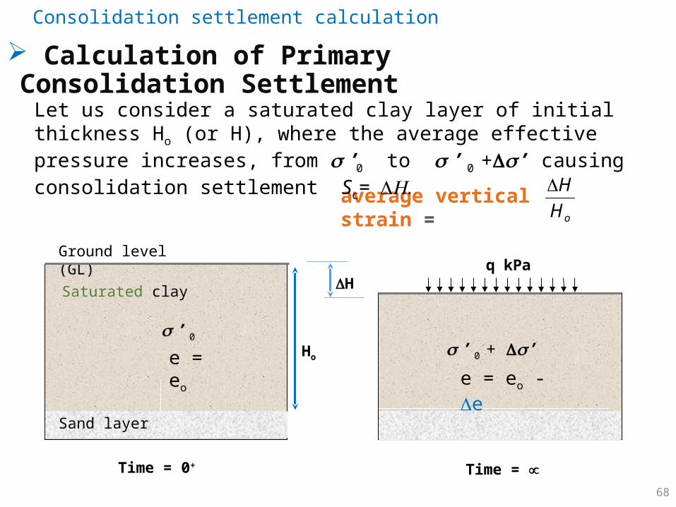
Saturated clay
Ground level (GL) q kPa
Ho
Time = 0+
e = eo
H
Time =
e = eo - e
average vertical strain = oH
H
Let us consider a saturated clay layer of initial thickness Ho (or H), where the average effective pressure increases, from s ’0 to s ’ 0 +Ds ’ causing consolidation settlement Sc= DH.
s ’ 0 + Ds ’
Sand layer
s ’ 0
Calculation of Primary Consolidation Settlement
Consolidation settlement calculation
69
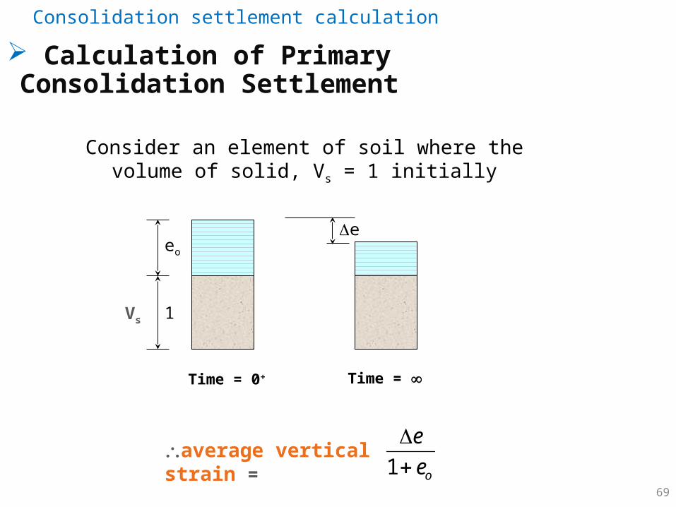
Consider an element of soil where the volume of solid, Vs = 1 initially
e
1
eo
Time = 0+ Time =
average vertical strain =oe
e
1
Vs
Calculation of Primary Consolidation Settlement
Consolidation settlement calculation

70
Equating the two expressions for average vertical strain,
oe
e
1
oH
H
consolidation settlement
initial thickness of clay layer initial void ratio
change in void ratio
as, Sc = DH
How to get the changes in void ratio De ?
Calculation of Primary Consolidation Settlement
Consolidation settlement calculation
Note: is also called 71
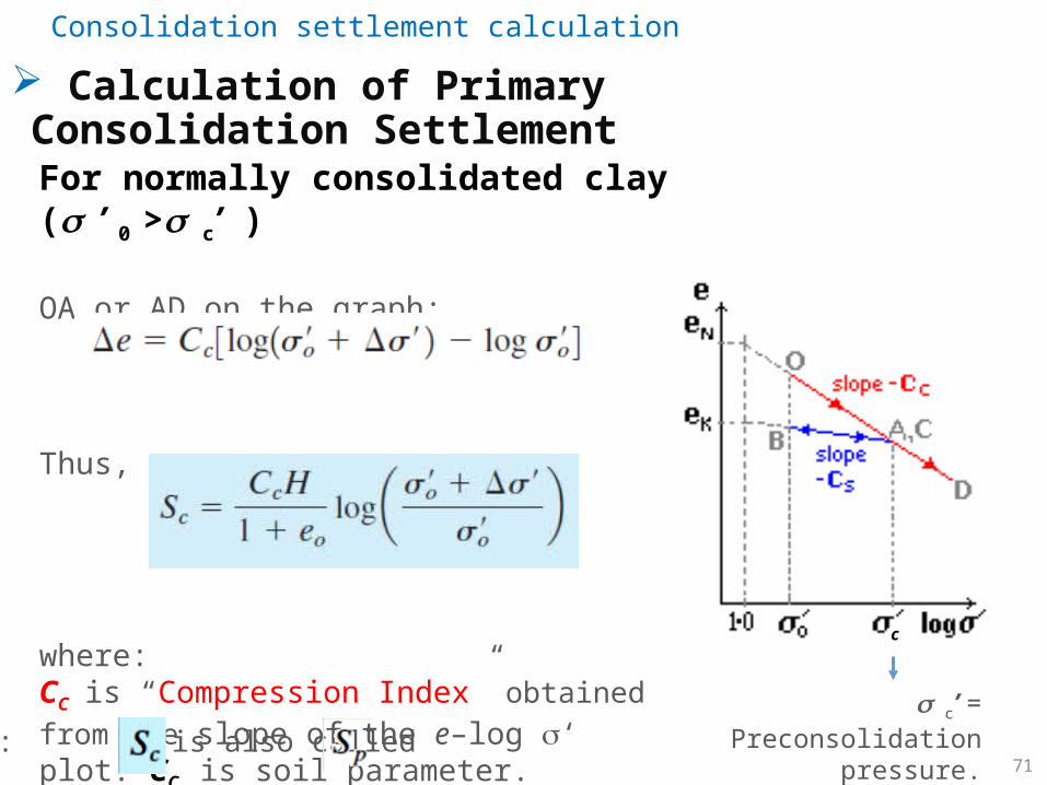
For normally consolidated clay ( s ’ 0 > s c’ )
OA or AD on the graph:
Thus,
where:CC is “Compression Index” obtained from the slope of the e–log s‘ plot. CC is soil parameter.
c
s c’ = Preconsolidation pressure.
Calculation of Primary Consolidation Settlement
Consolidation settlement calculation

72
For over-consolidated clay ( s ’ 0 < s c’ )
There are two cases:
• Case (1): when s ’ 0 +Ds ’ ≤ s c’
• Case (2): when s ’ 0 +Ds ’ > s c’
c
s c’ = Preconsolidation pressure.
Calculation of Primary Consolidation Settlement
Consolidation settlement calculation
CE 483 - Foundation Engineering - 5. Settlement of shallow foundations
73
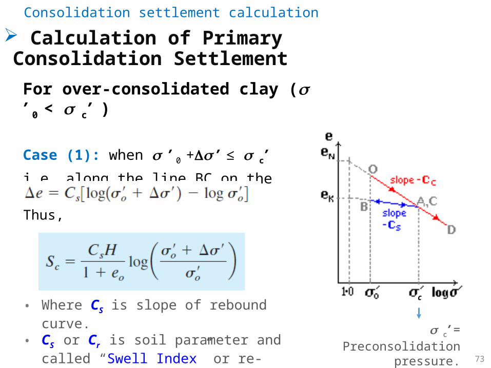
For over-consolidated clay ( s ’ 0 < s c’ )
Case (1): when s ’ 0 +Ds ’ ≤ s c’
i.e. along the line BC on the laboratory rebound curve.
Thus,
• Where CS is slope of rebound curve. • CS or Cr is soil parameter and called “Swell Index”
or re-compression index.
c
s c’ = Preconsolidation pressure.
Calculation of Primary Consolidation SettlementConsolidation settlement calculation

74
For over-consolidated clay ( s ’ 0 < s c’ )
Case (2): when s ’ 0 +Ds ’ > s c’
i.e. along the line BC then CD.
Thus,
• CS = Swell Index or recompression index Cr
• CC = Compression Index
c
s c’ = Pre-consolidation pressure.
Calculation of Primary Consolidation SettlementConsolidation settlement calculation
75
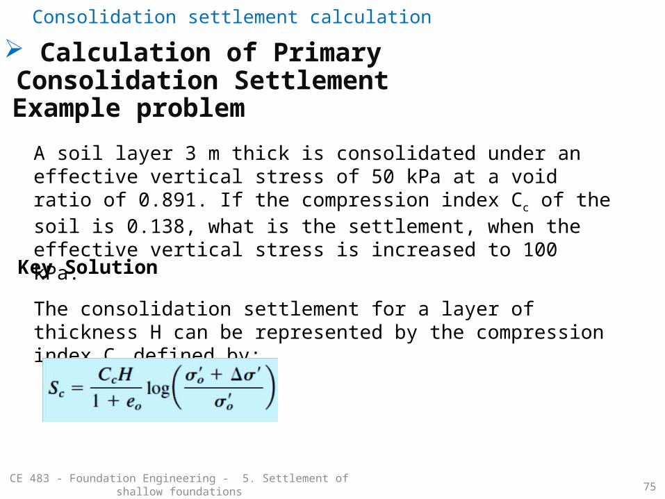
Example problem
A soil layer 3 m thick is consolidated under an effective vertical stress of 50 kPa at a void ratio of 0.891. If the compression index Cc of the soil is 0.138, what is the settlement, when the effective vertical stress is increased to 100 kPa.
Key Solution
The consolidation settlement for a layer of thickness H can be represented by the compression index Cc defined by:
Calculation of Primary Consolidation SettlementConsolidation settlement calculation
CE 483 - Foundation Engineering - 5. Settlement of shallow foundations

76
Example problem
A soil profile is shown in the figure. If a uniformly distributed load is applied at the ground surface, what will be the settlement of the clay layer caused by primary consolidation?
We are given that sc for the clay is 125 kN/m2 and Cs=1/6 Cc , where:
Consolidation settlement calculation
CE 483 - Foundation Engineering - 5. Settlement of shallow foundations
q

77
Solution
Consolidation settlement calculation
CE 483 - Foundation Engineering - 5. Settlement of shallow foundations
NOTE:If the loaded area is limited (e.g. rectangular foundation) we will need to compute the stress increase ‘ within the soil mass using Boussinesq method or other approach assuming elasticity.
For wide uniformly distributed load, such as given in the question, the stress increase at any depth, z, can be given as:
‘ = q = 50 kPa
The important procedure for determining consolidation settlement is to calculate:
• o‘ the initial effective pressure at the middle of compressible soil layer • ‘ the average net effective stress increase in the compressible soil layer.

78
Consolidation settlement calculation
CE 483 - Foundation Engineering - 5. Settlement of shallow foundations
Solution (cont..)

79
Solution (cont..)
Consolidation settlement calculation

80
Consolidation settlement calculation
Time rate of consolidation
CE 483 - Foundation Engineering - 5. Settlement of shallow foundations
• You learned above how to calculate the ultimate settlement of primary consolidation Sc (at the end of consolidation).
• However this settlement usually takes long time, much longer than the time of construction.
• And we may need to know the settlement at a specific time.
Time, t
Settlement, S(time)
End of Construction
End of primary consolidation

81
Consolidation settlement calculation
Time rate of consolidation
H ClayHdr
Hdr
Hdr
Permeable layer
Cv is obtained from laboratory testing
U = the degree of consolidation
CE 481 - Geotechnical Engineering II - 2. Compressibility of Soil 82
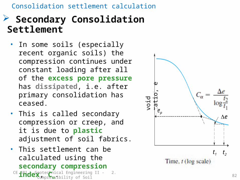
• In some soils (especially recent organic soils) the compression continues under constant loading after all of the excess pore pressure has dissipated, i.e. after primary consolidation has ceased.
• This is called secondary compression or creep, and it is due to plastic adjustment of soil fabrics.
• This settlement can be calculated using the secondary compression index, Ca.
• The Log-Time plot (of the consolidation test) can be used to estimate the coefficient of secondary compression Ca.
void
rati
o,
et1 t2
Deep
Secondary Consolidation SettlementConsolidation settlement calculation
83
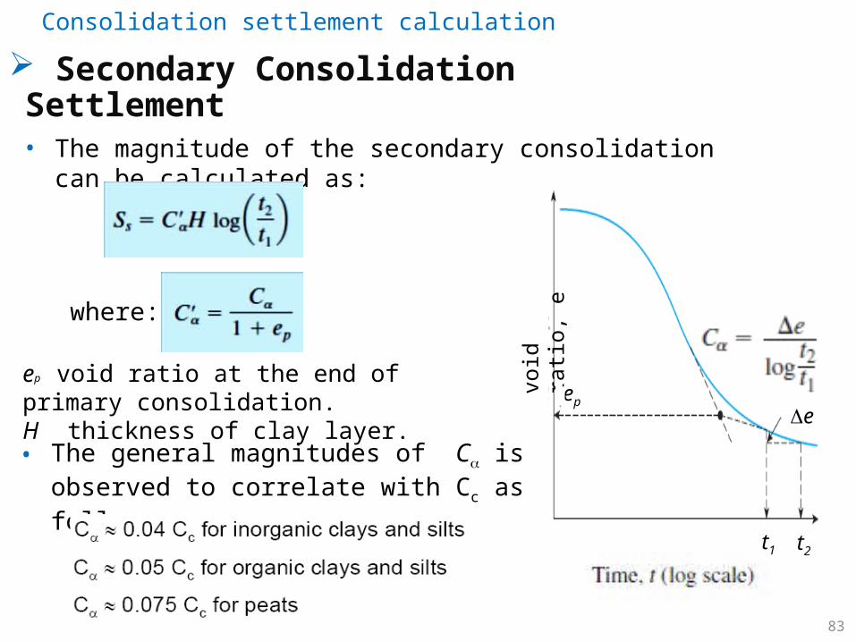
• The magnitude of the secondary consolidation can be calculated as:
void
rati
o,
et1 t2
Deep
where:
ep void ratio at the end of primary consolidation.H thickness of clay layer.• The general magnitudes of Ca is observed to
correlate with Cc as follows:
Secondary Consolidation SettlementConsolidation settlement calculation
Field test (Bearing capacity with settlement consideration)
CE 483 - Foundation Engineering - 5. Settlement of shallow foundations 84
Plate load test Standard Penetration Test (SPT) Cone Penetration Test (CPT)

85
Field test (Bearing capacity with settlement consideration)
Plate load test
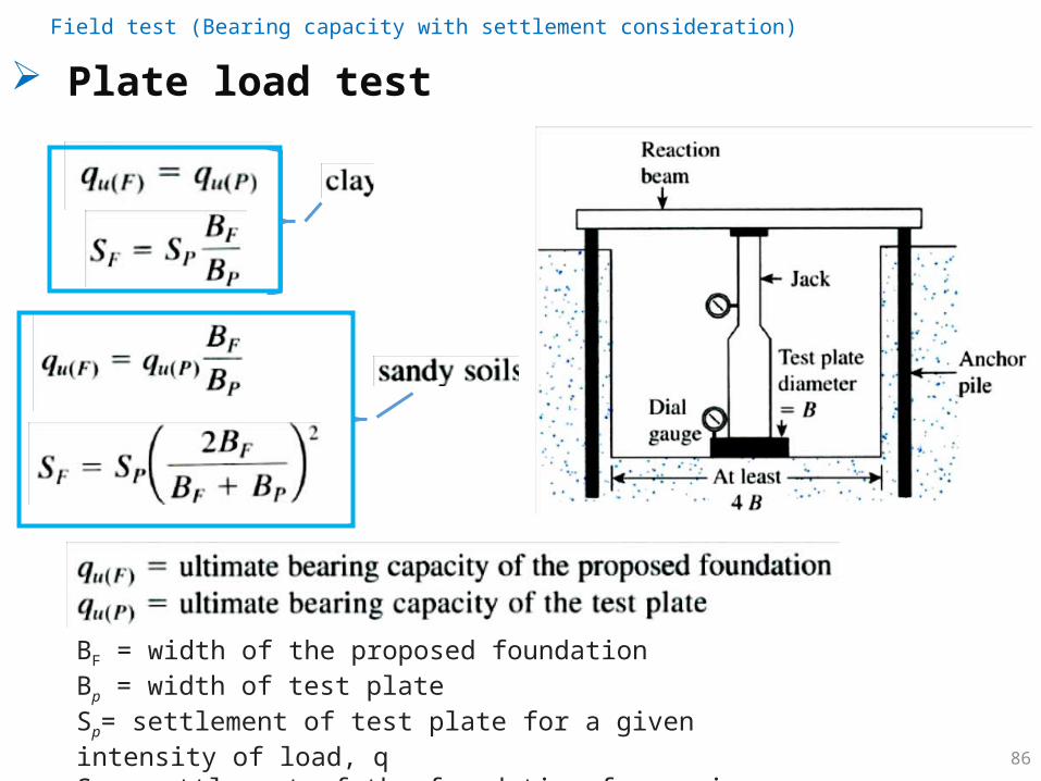
Plate Load Test is a field test for determining the ultimate bearing capacity of soil and the likely settlement under a given load (ASTM D-1194-72).
The Plate Load Test basically consists of loading a steel plate placed at the foundation level and recording the settlements corresponding to each load increment.
86
Plate load test
BF = width of the proposed foundation Bp = width of test plateSp= settlement of test plate for a given intensity of load, qSF = settlement of the foundation for a given intensity of load, q
Field test (Bearing capacity with settlement consideration)
87
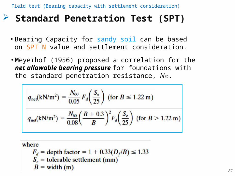
Standard Penetration Test (SPT)
• Bearing Capacity for sandy soil can be based on SPT N value and settlement consideration.
• Meyerhof (1956) proposed a correlation for the net allowable bearing pressure for foundations with the standard penetration resistance, N60.
Field test (Bearing capacity with settlement consideration)
88
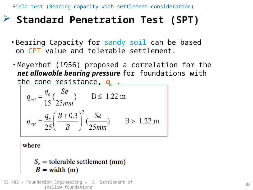
Standard Penetration Test (SPT)
• Bearing Capacity for sandy soil can be based on CPT value and tolerable settlement.
• Meyerhof (1956) proposed a correlation for the net allowable bearing pressure for foundations with the cone resistance, qc .
Field test (Bearing capacity with settlement consideration)
CE 483 - Foundation Engineering - 5. Settlement of shallow foundations
References
89CE 483 - Foundation Engineering - 5. Settlement of shallow foundations
1. Braja M Das, 2011, Principles of Foundation Engineering, 7th ed, Chapter- 5.
2. Previous course materials and presentations at KSU.3. Geotechnical on the web:
http://environment.uwe.ac.uk/geocal/foundations/founbear.htm.4. Andrew Bond and Andrew Harris, 2008, Decoding Eurocode 7, London.5. The Institution of Structural Engineers library:
www.istructe.org/resources-centre/library