Embed Size (px)
Citation preview
SITRANS F
Communication ModulesFOUNDATION FIELDBUS H1
Operating Instructions • 11/2008

Introduction 1
Safety notes
2
Hardware installation
3
Connecting
4
Block overview
5
System integration
6
Alarm, error, and system messages
7
Troubleshooting/FAQs
8
Technical data
9
Appendix A
A
Appendix B
B
List of abbreviations
C
SITRANS F
Communication ModulesFoundation Fieldbus H1
Operating Instructions
11/2008 SFI.DK.PS.023.H1.02
Add-on module for use with transmitter types SITRANS F M MAG 6000 and SITRANS F C MASS 6000.
Legal information Warning notice system
This manual contains notices you have to observe in order to ensure your personal safety, as well as to prevent damage to property. The notices referring to your personal safety are highlighted in the manual by a safety alert symbol, notices referring only to property damage have no safety alert symbol. These notices shown below are graded according to the degree of danger.
DANGER indicates that death or severe personal injury will result if proper precautions are not taken.
WARNING indicates that death or severe personal injury may result if proper precautions are not taken.
CAUTION with a safety alert symbol, indicates that minor personal injury can result if proper precautions are not taken.
CAUTION without a safety alert symbol, indicates that property damage can result if proper precautions are not taken.
NOTICE indicates that an unintended result or situation can occur if the corresponding information is not taken into account.
If more than one degree of danger is present, the warning notice representing the highest degree of danger will be used. A notice warning of injury to persons with a safety alert symbol may also include a warning relating to property damage.
Qualified Personnel The device/system may only be set up and used in conjunction with this documentation. Commissioning and operation of a device/system may only be performed by qualified personnel. Within the context of the safety notes in this documentation qualified persons are defined as persons who are authorized to commission, ground and label devices, systems and circuits in accordance with established safety practices and standards.
Proper use of Siemens products Note the following:
WARNING Siemens products may only be used for the applications described in the catalog and in the relevant technical documentation. If products and components from other manufacturers are used, these must be recommended or approved by Siemens. Proper transport, storage, installation, assembly, commissioning, operation and maintenance are required to ensure that the products operate safely and without any problems. The permissible ambient conditions must be adhered to. The information in the relevant documentation must be observed.
Trademarks All names identified by ® are registered trademarks of the Siemens AG. The remaining trademarks in this publication may be trademarks whose use by third parties for their own purposes could violate the rights of the owner.
Disclaimer of Liability We have reviewed the contents of this publication to ensure consistency with the hardware and software described. Since variance cannot be precluded entirely, we cannot guarantee full consistency. However, the information in this publication is reviewed regularly and any necessary corrections are included in subsequent editions.
Siemens AG Industry Sector Postfach 48 48 90026 NÜRNBERG GERMANY
Ordernumber: A5E02318728 Ⓟ 11/2008
Copyright © Siemens AG 2008. Technical data subject to change
Foundation Fieldbus H1 Operating Instructions, 11/2008, SFI.DK.PS.023.H1.02 3
Table of contents
1 Introduction................................................................................................................................................ 7
1.1 Foundation Fieldbus technology....................................................................................................7 1.2 Items supplied................................................................................................................................8 1.3 History ............................................................................................................................................8 1.4 Further Information ........................................................................................................................8
2 Safety notes............................................................................................................................................... 9 2.1 General safety instructions ............................................................................................................9 2.2 Installation in hazardous area........................................................................................................9
3 Hardware installation ............................................................................................................................... 11 3.1 MAG/MASS 6000 IP67 or 19"......................................................................................................11 3.2 MAG 6000 I ..................................................................................................................................13 3.3 MASS 6000 Ex d..........................................................................................................................14
4 Connecting .............................................................................................................................................. 17 4.1 General instructions .....................................................................................................................17 4.2 Connecting...................................................................................................................................17
5 Block overview......................................................................................................................................... 21 5.1 Basic description (RB, TB, FB) ....................................................................................................21 5.2 Block structure .............................................................................................................................22 5.3 Resource Block............................................................................................................................23 5.4 Transducer blocks........................................................................................................................25 5.4.1 Signal processing.........................................................................................................................25 5.4.2 Operating mode selection ............................................................................................................28 5.4.3 Flow Transducer Block ................................................................................................................28 5.4.4 Totalizer Transducer Blocks ........................................................................................................29 5.4.5 Batch Transducer Block...............................................................................................................30 5.4.6 Diagnosis Transducer Block ........................................................................................................31 5.4.7 Input/output Transducer Block .....................................................................................................32 5.4.8 Display Transducer Block ............................................................................................................32 5.5 Function blocks ............................................................................................................................32 5.5.1 Analog Input Function Blocks ......................................................................................................33 5.5.2 Discrete Output Function Blocks..................................................................................................37
6 System integration ................................................................................................................................... 39 6.1 Introduction ..................................................................................................................................39 6.2 Function check.............................................................................................................................39 6.3 Parameter access ........................................................................................................................39 6.4 Simulation HW jumper .................................................................................................................40
Table of contents
Foundation Fieldbus H1 4 Operating Instructions, 11/2008, SFI.DK.PS.023.H1.02
6.5 Step by step guide to commissioning ......................................................................................... 40 6.5.1 Step 1: Prepare commissioning .................................................................................................. 41 6.5.2 Step 2: Configure Resource Block.............................................................................................. 42 6.5.3 Step 3: Configure Transducer Blocks ......................................................................................... 43 6.5.4 Step 4: Configure Analog Input FB ............................................................................................. 43 6.5.5 Step 5: Configure Discrete Output FB ........................................................................................ 46
7 Alarm, error, and system messages ........................................................................................................ 47 7.1 Introduction ................................................................................................................................. 47 7.2 Block errors and block alarms..................................................................................................... 47 7.3 Detailed error information............................................................................................................ 48 7.4 Resource Block diagnostic information....................................................................................... 50 7.5 Flow TB diagnostic information................................................................................................... 52 7.6 Totalizer 1 and 2 TB diagnostic information................................................................................ 54 7.7 Batch TB diagnostic information ................................................................................................. 56 7.8 Diagnosis TB diagnostic information........................................................................................... 58 7.9 Input/Output TB diangostic information....................................................................................... 59 7.10 Error examples............................................................................................................................ 61
8 Troubleshooting/FAQs............................................................................................................................. 63 8.1 Device error messages ............................................................................................................... 63 8.2 Analog Input FB cannot be set to AUTO..................................................................................... 66 8.3 Parameter cannot be written....................................................................................................... 66 8.4 PID Block cannot be set to AUTO............................................................................................... 66
9 Technical data ......................................................................................................................................... 67 9.1 Cable specifications .................................................................................................................... 68
A Appendix A .............................................................................................................................................. 71 A.1 General information..................................................................................................................... 71 A.2 Resource Block parameters........................................................................................................ 72 A.3 Transducer Block parameters..................................................................................................... 79 A.3.1 Flow TB (TB1) ............................................................................................................................. 79 A.3.2 Totalizer 1 TB (TB2).................................................................................................................... 90 A.3.3 Totalizer 2 TB (TB3).................................................................................................................... 92 A.3.4 Batch TB (TB4) ........................................................................................................................... 95 A.3.5 Diagnosis TB (TB5)................................................................................................................... 100 A.3.6 Input / Output TB (TB6)............................................................................................................. 102 A.3.7 Local Display TB (TB7) ............................................................................................................. 111
B Appendix B ............................................................................................................................................ 117 B.1 Data sets ................................................................................................................................... 117
C List of abbreviations............................................................................................................................... 121 Glossary ................................................................................................................................................ 123 Index...................................................................................................................................................... 125
Table of contents
Foundation Fieldbus H1 Operating Instructions, 11/2008, SFI.DK.PS.023.H1.02 5
Tables
Table 5- 1 Resource Block Status.................................................................................................................24 Table 5- 2 Transducer Blocks .......................................................................................................................25 Table 5- 3 MASS 6000 output channels .......................................................................................................26 Table 5- 4 MASS 6000 input channels..........................................................................................................27 Table 5- 5 MAG 6000 output channels .........................................................................................................27 Table 5- 6 MAG 6000 input channels............................................................................................................27 Table 5- 7 Totalizer TB channels ..................................................................................................................29 Table 5- 8 Batch TB channels.......................................................................................................................31 Table 5- 9 Function Blocks............................................................................................................................33 Table 5- 10 Analog Input FB signal processing ..............................................................................................34 Table 5- 11 Analog Input FBs .........................................................................................................................35 Table 5- 12 Discrete Output FB channels .......................................................................................................37 Table 6- 1 Block structure .............................................................................................................................41 Table 7- 1 BLOCK_ERR parameters ............................................................................................................47 Table 7- 2 Analog Input FB process alarms..................................................................................................48 Table 7- 3 Detailed error information ............................................................................................................49 Table 7- 4 Resource block error bits (standard) ...........................................................................................50 Table 7- 5 DETAILED_ERROR_INFO_1 ......................................................................................................51 Table 7- 6 Flow TB diagnostic information (standard) ..................................................................................52 Table 7- 7 Flow TB detailed error information 1............................................................................................53 Table 7- 8 Flow TB detailed error information 2............................................................................................53 Table 7- 9 Totalizer 1 and 2 TB diagnostic information (standard)...............................................................54 Table 7- 10 Totalizer 1 and 2 TB detailed error information 1 ........................................................................55 Table 7- 11 Totalizer 1 and 2 TB detailed error information 2 ........................................................................55 Table 7- 12 Batch TB diagnostic information (standard).................................................................................56 Table 7- 13 Batch TB detailed error information 1 ..........................................................................................57 Table 7- 14 Batch TB detailed error information 2 ..........................................................................................57 Table 7- 15 Diagnosis TB diagnostic information (standard) ..........................................................................58 Table 7- 16 Diagnosis TB detailed error information 1 ...................................................................................58 Table 7- 17 Diagnostic TB detailed error information 2 ..................................................................................59 Table 7- 18 Diagnostic TB detailed error information 3 ..................................................................................59 Table 7- 19 Input/Output TB diagnostic information (standard) ......................................................................60 Table 7- 20 Input/output TB detailed diagnostic information 1........................................................................60 Table 8- 1 Error messages............................................................................................................................63 Table 9- 1 General specifications..................................................................................................................67
Table of contents
Foundation Fieldbus H1 6 Operating Instructions, 11/2008, SFI.DK.PS.023.H1.02
Table 9- 2 Physical layer specifications ....................................................................................................... 67 Table 9- 3 IS (Intrinsic Safety) data.............................................................................................................. 67 Table 9- 4 Recommended cable types......................................................................................................... 68 Table A- 1 Attributes of parameter tables..................................................................................................... 71 Table A- 2 Resource Block parameters........................................................................................................ 72 Table A- 3 Flow TB parameters.................................................................................................................... 79 Table A- 4 Totalizer 1 TB parameters........................................................................................................... 90 Table A- 5 Totalizer 2 TB parameters........................................................................................................... 92 Table A- 6 Batch TB parameters .................................................................................................................. 95 Table A- 7 Diagnosis TB parameters.......................................................................................................... 100 Table A- 8 Input/output TB parameters ...................................................................................................... 102 Table A- 9 Local Display TB parameters.................................................................................................... 111 Table B- 1 DS 64: Block ............................................................................................................................. 117 Table B- 2 DS 65: Value & Status – Floating Point Structure..................................................................... 117 Table B- 3 DS 66: Value & Status – Discrete Structure.............................................................................. 117 Table B- 4 DS 68: Scaling Structure........................................................................................................... 117 Table B- 5 DS 69: Mode Structure.............................................................................................................. 118 Table B- 6 DS 70: Access Permissions...................................................................................................... 118 Table B- 7 DS 71: Alarm Float Structure .................................................................................................... 118 Table B- 8 DS 72: Alarm Discrete Structure............................................................................................... 118 Table B- 9 DS 73: Event Update Structure................................................................................................. 118 Table B- 10 DS 74: Alarm Summary Structure............................................................................................. 119 Table B- 11 DS 82: Simulate – Floating Point Structure............................................................................... 119 Table B- 12 DS 82: Test Structure................................................................................................................ 119
Figures
Figure 4-1 Electrical connection ................................................................................................................... 18 Figure 5-1 FF block overview ....................................................................................................................... 22 Figure 5-2 MASS 6000 signal processing .................................................................................................... 26 Figure 5-3 MAG 6000 signal processing ...................................................................................................... 27 Figure 5-4 Analog Input FB Signal Processing ............................................................................................ 34 Figure 6-1 FF menu structure....................................................................................................................... 41 Figure 6-2 L_TYPE = direct .......................................................................................................................... 45 Figure 6-3 L_TYPE = Indirect ....................................................................................................................... 46
Foundation Fieldbus H1 Operating Instructions, 11/2008, SFI.DK.PS.023.H1.02 7
Introduction 1
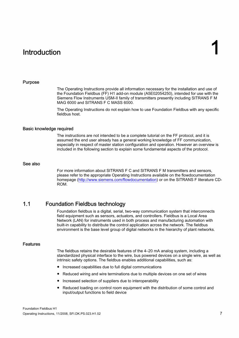
Purpose The Operating Instructions provide all information necessary for the installation and use of the Foundation Fieldbus (FF) H1 add-on module (A5E02054250), intended for use with the Siemens Flow Instruments USM-II family of transmitters presently including SITRANS F M MAG 6000 and SITRANS F C MASS 6000. The Operating Instructions do not explain how to use Foundation Fieldbus with any specific fieldbus host.
Basic knowledge required The instructions are not intended to be a complete tutorial on the FF protocol, and it is assumed the end user already has a general working knowledge of FF communication, especially in respect of master station configuration and operation. However an overview is included in the following section to explain some fundamental aspects of the protocol.
See also For more information about SITRANS F C and SITRANS F M transmitters and sensors, please refer to the appropriate Operating Instructions available on the flowdocumentation homepage (http://www.siemens.com/flowdocumentation) or on the SITRANS F literature CD-ROM.
1.1 Foundation Fieldbus technology Foundation fieldbus is a digital, serial, two-way communication system that interconnects field equipment such as sensors, actuators, and controllers. Fieldbus is a Local Area Network (LAN) for instruments used in both process and manufacturing automation with built-in capability to distribute the control application across the network. The fieldbus environment is the base level group of digital networks in the hierarchy of plant networks.
Features The fieldbus retains the desirable features of the 4–20 mA analog system, including a standardized physical interface to the wire, bus powered devices on a single wire, as well as intrinsic safety options. The fieldbus enables additional capabilities, such as: ● Increased capabilities due to full digital communications ● Reduced wiring and wire terminations due to multiple devices on one set of wires ● Increased selection of suppliers due to interoperability ● Reduced loading on control room equipment with the distribution of some control and
input/output functions to field device
Introduction 1.2 Items supplied
Foundation Fieldbus H1 8 Operating Instructions, 11/2008, SFI.DK.PS.023.H1.02
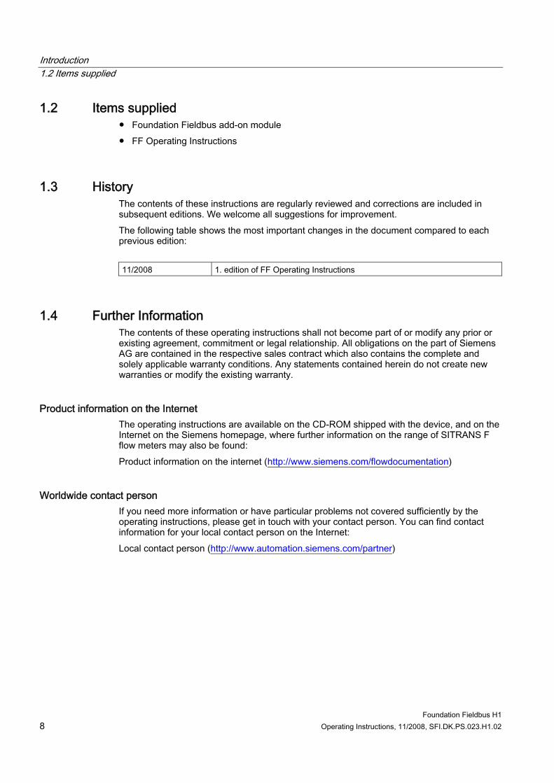
1.2 Items supplied ● Foundation Fieldbus add-on module ● FF Operating Instructions
1.3 History The contents of these instructions are regularly reviewed and corrections are included in subsequent editions. We welcome all suggestions for improvement. The following table shows the most important changes in the document compared to each previous edition: 11/2008 1. edition of FF Operating Instructions
1.4 Further Information The contents of these operating instructions shall not become part of or modify any prior or existing agreement, commitment or legal relationship. All obligations on the part of Siemens AG are contained in the respective sales contract which also contains the complete and solely applicable warranty conditions. Any statements contained herein do not create new warranties or modify the existing warranty.
Product information on the Internet The operating instructions are available on the CD-ROM shipped with the device, and on the Internet on the Siemens homepage, where further information on the range of SITRANS F flow meters may also be found: Product information on the internet (http://www.siemens.com/flowdocumentation)
Worldwide contact person If you need more information or have particular problems not covered sufficiently by the operating instructions, please get in touch with your contact person. You can find contact information for your local contact person on the Internet: Local contact person (http://www.automation.siemens.com/partner)
Foundation Fieldbus H1 Operating Instructions, 11/2008, SFI.DK.PS.023.H1.02 9
Safety notes 22.1 General safety instructions
CAUTION Correct, reliable operation of the product requires proper transport, storage, positioning and assembly as well as careful operation and maintenance. Only qualified personnel should install or operate this instrument.
Note Alterations to the product, including opening or improper repairs of the product, are not permitted. If this requirement is not observed, the CE mark and the manufacturer's warranty will expire.
2.2 Installation in hazardous area In general the FF output is Non-Ex, except when installed in a Compact SITRANS F C MASS 6000 Ex d or a SITRANS F M MAG 6000 I Ex d.
WARNING Before installing in hazardous area, refer to the Operating Instructions of the relevant transmitter.

Safety notes 2.2 Installation in hazardous area
Foundation Fieldbus H1 10 Operating Instructions, 11/2008, SFI.DK.PS.023.H1.02
Foundation Fieldbus H1 Operating Instructions, 11/2008, SFI.DK.PS.023.H1.02 11
Hardware installation 3
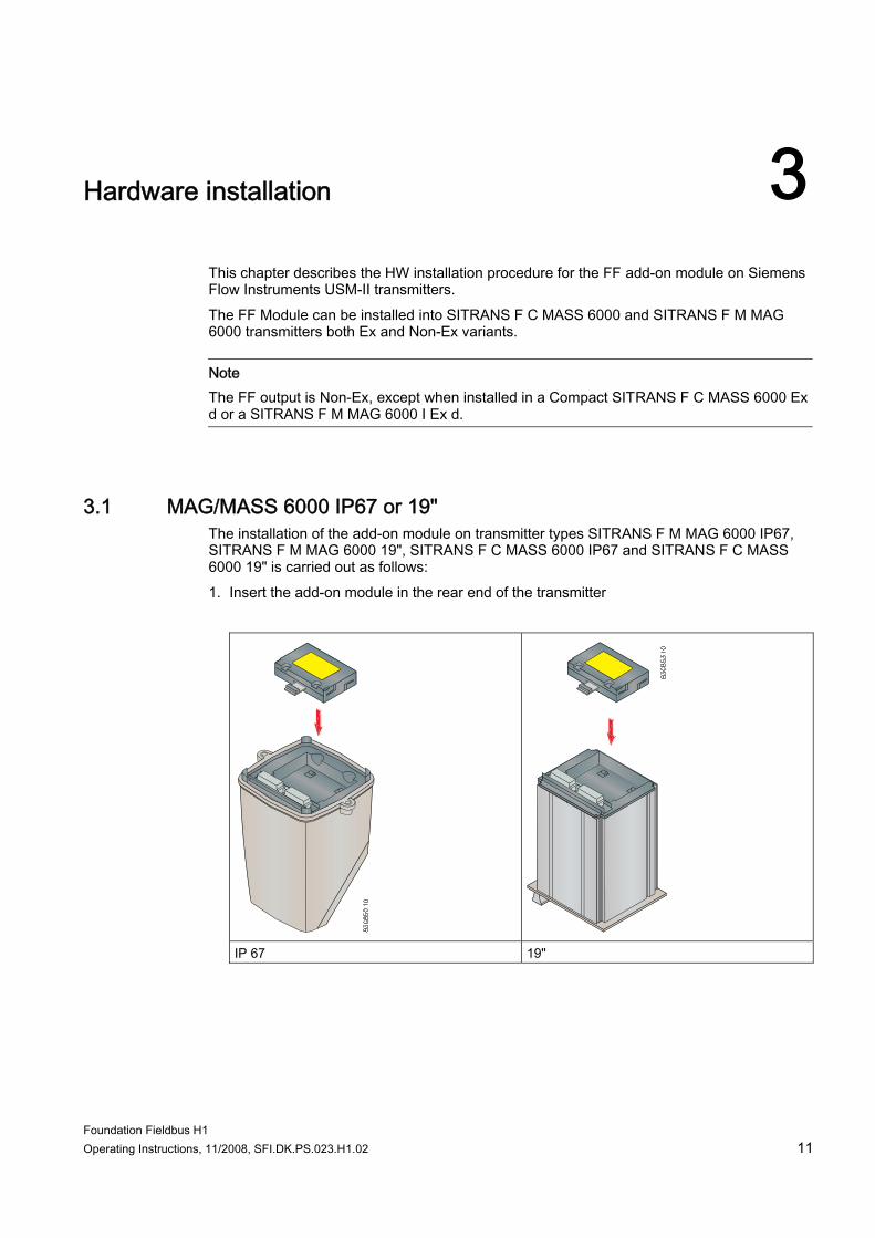
This chapter describes the HW installation procedure for the FF add-on module on Siemens Flow Instruments USM-II transmitters. The FF Module can be installed into SITRANS F C MASS 6000 and SITRANS F M MAG 6000 transmitters both Ex and Non-Ex variants.
Note The FF output is Non-Ex, except when installed in a Compact SITRANS F C MASS 6000 Ex d or a SITRANS F M MAG 6000 I Ex d.
3.1 MAG/MASS 6000 IP67 or 19" The installation of the add-on module on transmitter types SITRANS F M MAG 6000 IP67, SITRANS F M MAG 6000 19", SITRANS F C MASS 6000 IP67 and SITRANS F C MASS 6000 19" is carried out as follows: 1. Insert the add-on module in the rear end of the transmitter
IP 67 19"
Hardware installation 3.1 MAG/MASS 6000 IP67 or 19"
Foundation Fieldbus H1 12 Operating Instructions, 11/2008, SFI.DK.PS.023.H1.02
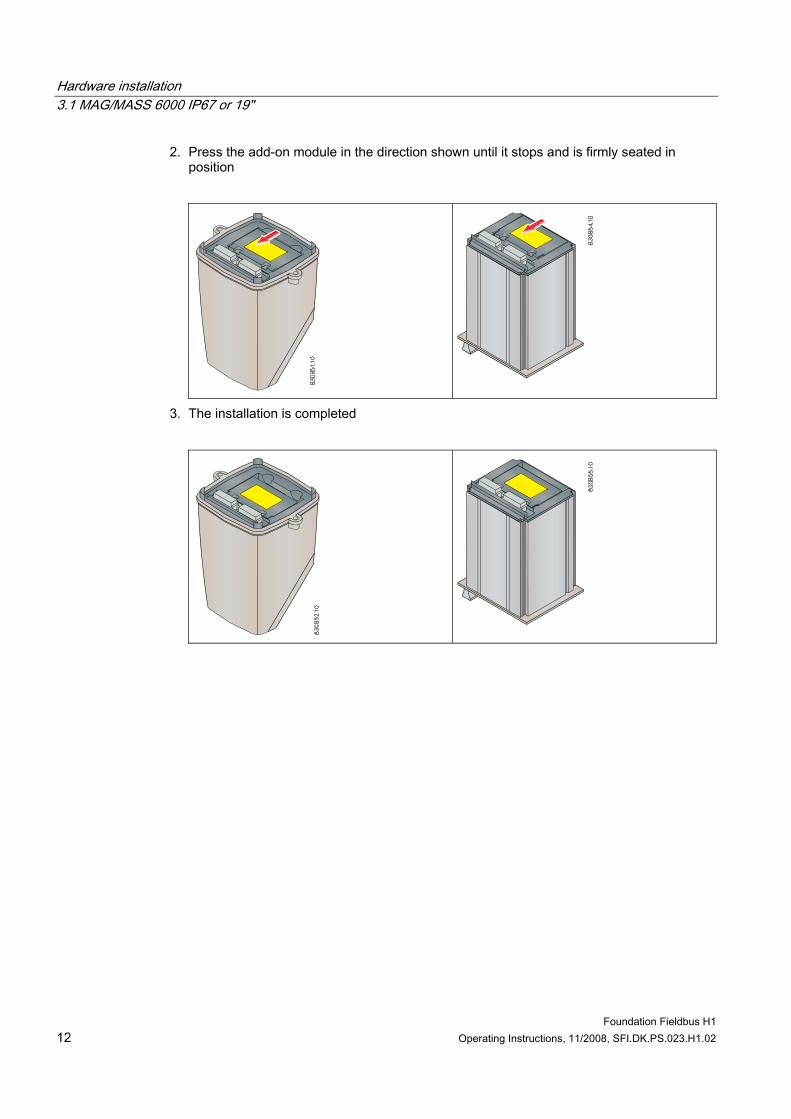
2. Press the add-on module in the direction shown until it stops and is firmly seated in position
3. The installation is completed
Hardware installation 3.2 MAG 6000 I
Foundation Fieldbus H1 Operating Instructions, 11/2008, SFI.DK.PS.023.H1.02 13
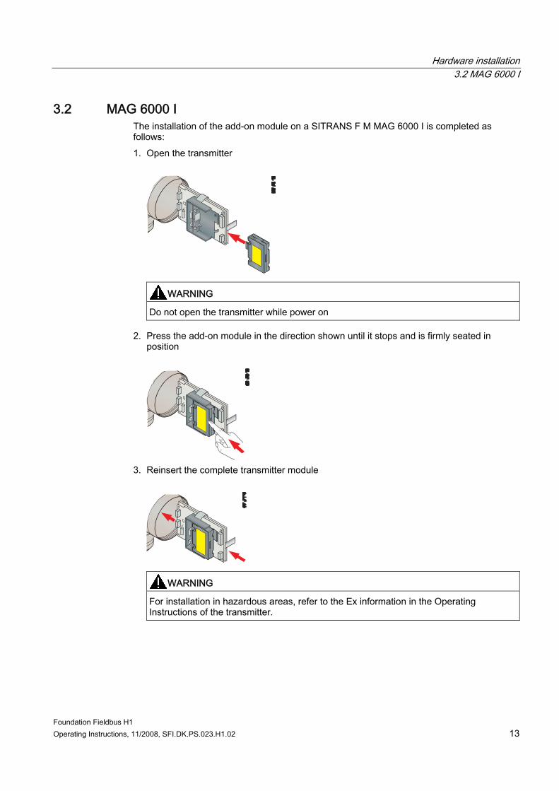
3.2 MAG 6000 I The installation of the add-on module on a SITRANS F M MAG 6000 I is completed as follows: 1. Open the transmitter
WARNING
Do not open the transmitter while power on
2. Press the add-on module in the direction shown until it stops and is firmly seated in position
3. Reinsert the complete transmitter module
WARNING
For installation in hazardous areas, refer to the Ex information in the Operating Instructions of the transmitter.
Hardware installation 3.3 MASS 6000 Ex d
Foundation Fieldbus H1 14 Operating Instructions, 11/2008, SFI.DK.PS.023.H1.02
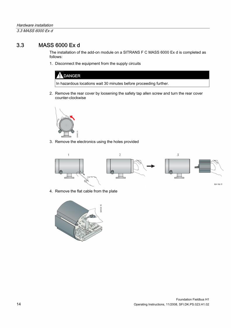
3.3 MASS 6000 Ex d The installation of the add-on module on a SITRANS F C MASS 6000 Ex d is completed as follows: 1. Disconnect the equipment from the supply circuits
DANGER
In hazardous locations wait 30 minutes before proceeding further.
2. Remove the rear cover by loosening the safety tap allen screw and turn the rear cover counter-clockwise
3. Remove the electronics using the holes provided
4. Remove the flat cable from the plate
Hardware installation 3.3 MASS 6000 Ex d
Foundation Fieldbus H1 Operating Instructions, 11/2008, SFI.DK.PS.023.H1.02 15
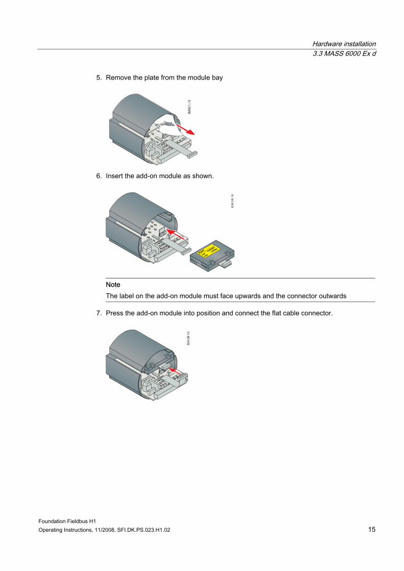
5. Remove the plate from the module bay
6. Insert the add-on module as shown.
Note The label on the add-on module must face upwards and the connector outwards
7. Press the add-on module into position and connect the flat cable connector.

Hardware installation 3.3 MASS 6000 Ex d
Foundation Fieldbus H1 16 Operating Instructions, 11/2008, SFI.DK.PS.023.H1.02
Foundation Fieldbus H1 Operating Instructions, 11/2008, SFI.DK.PS.023.H1.02 17
Connecting 44.1 General instructions
On the electrical termination boards for USM-II transmitters, additional input/output terminals have been reserved for add-on module functions. The numbering range of these terminals is as follows, but how many are actually used depends on the type of add-on module. Additional terminals reserved for add-on modules: ● MAG 6000: 91 - 97 ● MASS 6000: 91 – 100
Note The standard inputs and outputs continue to function and are not affected by the presence of an add-on module. Any existing transmitter electrical connections remain undisturbed. The MASS 6000 with extra outputs, i.e. 3 current outputs, cannot be extended with an add-on module
WARNING
Only authorized personnel are allowed to carry to carry out work on electrical connections.
Please refer to the relevant product operating instruction for other electrical connection information.
4.2 Connecting Terminals 95 and 96 are reserved for the Foundation Fieldbus H1 connection. The FF interface is polarity independent, so the wires can be connected arbitrarily. ● 95: FF wire 1. This device is polarity independent ● 96: FF wire 2. This device is polarity independent To achieve the best EMC performance, the unshielded wires should be as short as possible, 2-3 cm. Shield coverage of 90% is ideal.
CAUTION Protection from electromagnetic interference It is recommended to use shielded twin core cables for connecting Foundation Fieldbus H1 to the SITRANS F transmitter.
Connecting 4.2 Connecting
Foundation Fieldbus H1 18 Operating Instructions, 11/2008, SFI.DK.PS.023.H1.02
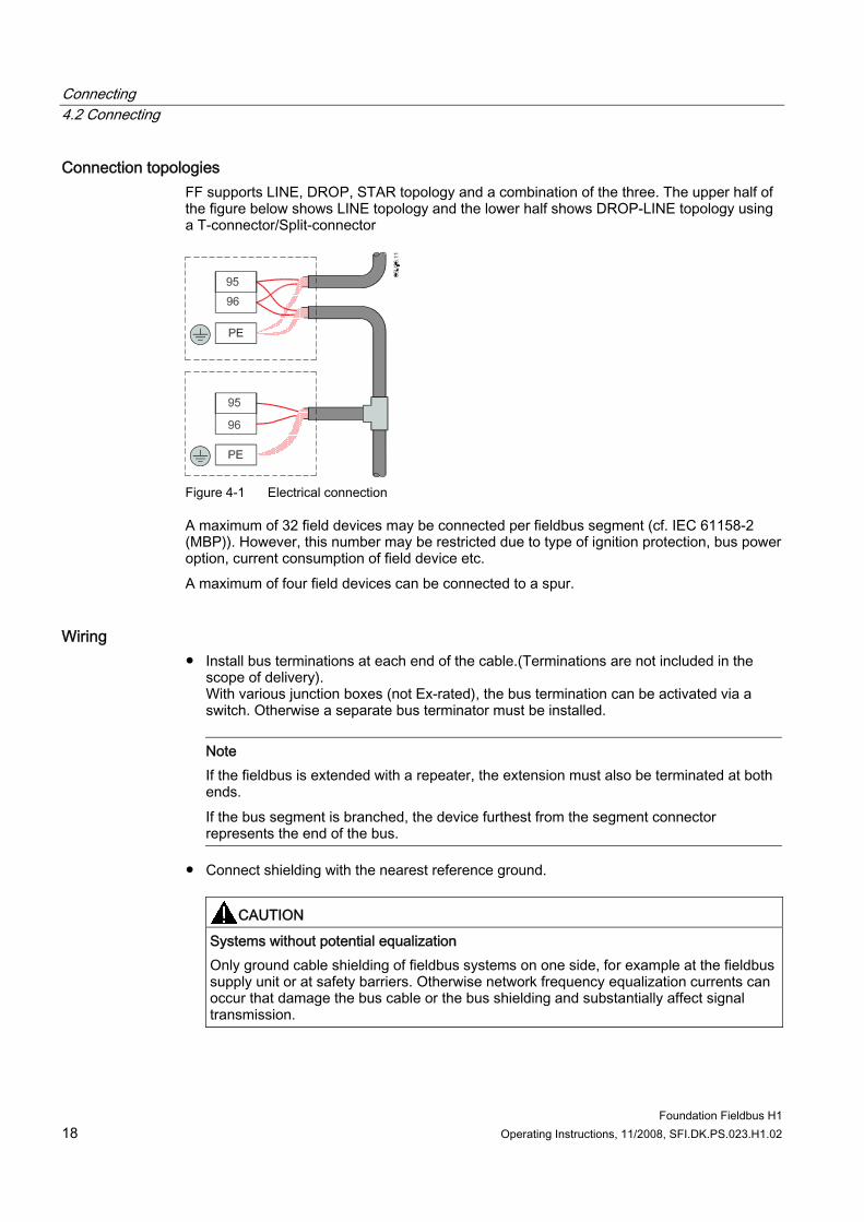
Connection topologies FF supports LINE, DROP, STAR topology and a combination of the three. The upper half of the figure below shows LINE topology and the lower half shows DROP-LINE topology using a T-connector/Split-connector
Figure 4-1 Electrical connection
A maximum of 32 field devices may be connected per fieldbus segment (cf. IEC 61158-2 (MBP)). However, this number may be restricted due to type of ignition protection, bus power option, current consumption of field device etc. A maximum of four field devices can be connected to a spur.
Wiring ● Install bus terminations at each end of the cable.(Terminations are not included in the
scope of delivery). With various junction boxes (not Ex-rated), the bus termination can be activated via a switch. Otherwise a separate bus terminator must be installed.
Note If the fieldbus is extended with a repeater, the extension must also be terminated at both ends. If the bus segment is branched, the device furthest from the segment connector represents the end of the bus.
● Connect shielding with the nearest reference ground.
CAUTION
Systems without potential equalization Only ground cable shielding of fieldbus systems on one side, for example at the fieldbus supply unit or at safety barriers. Otherwise network frequency equalization currents can occur that damage the bus cable or the bus shielding and substantially affect signal transmission.
Connecting 4.2 Connecting
Foundation Fieldbus H1 Operating Instructions, 11/2008, SFI.DK.PS.023.H1.02 19
Installation check ● Make sure that the installation guidelines provided by the "Wiring & Installation
Application Guide" on the Fieldbus Foundation website (http://www.fieldbus.org/) are followed
● Make sure the wiring requirements for the device are met. ● Make sure that all connectors are properly tightened.
Further information General information and further notes on connections can be found on the Fieldbus Foundation website (http://www.fieldbus.org/)

Connecting 4.2 Connecting
Foundation Fieldbus H1 20 Operating Instructions, 11/2008, SFI.DK.PS.023.H1.02
Foundation Fieldbus H1 Operating Instructions, 11/2008, SFI.DK.PS.023.H1.02 21
Block overview 55.1 Basic description (RB, TB, FB)
Block model All device parameters in Foundation Fieldbus protocol are categorized in different blocks according to their functional properties. These different types of blocks contain groups of parameters with associated functionalities. The FF protocol includes: ● A Resource Block (RB)
The Resource Block contains device-specific characteristics of the device. Each device has one Resource Block
● One or more Transducer Blocks (TB) The Transducer Block contains the measuring technology and device-specific data of the device. The Transducer Block data is independent of the automation application.
● One or more Function Blocks (FB) Function Blocks specify the automation functions of the device and compose parameters and algorithms that control functionality of the application system. Function Blocks are used as building blocks in defining the monitoring and control application.
Signal processing The flow measurement signal coming from the sensor is first prepared in the Transducer Block (i.e. Flow Transducer Block). The output of the Transducer Block is passed to another Transducer Block (e.g. Totalizer Transducer Block) or to a Function Block (e.g. Analog Input Function Block) for control related processing (e.g. scaling or limit value processing). The Function Block processes the input value (i.e. process value) with built-in algorithms and makes it available to other Function Blocks, e.g. the PID Block. Individual blocks can be connected to realize different automation tasks.
Block overview 5.2 Block structure
Foundation Fieldbus H1 22 Operating Instructions, 11/2008, SFI.DK.PS.023.H1.02
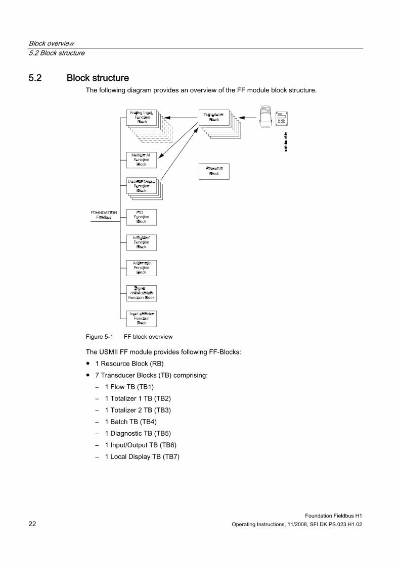
5.2 Block structure The following diagram provides an overview of the FF module block structure.
Figure 5-1 FF block overview
The USMII FF module provides following FF-Blocks: ● 1 Resource Block (RB) ● 7 Transducer Blocks (TB) comprising:
– 1 Flow TB (TB1) – 1 Totalizer 1 TB (TB2) – 1 Totalizer 2 TB (TB3) – 1 Batch TB (TB4) – 1 Diagnostic TB (TB5) – 1 Input/Output TB (TB6) – 1 Local Display TB (TB7)
Block overview 5.3 Resource Block
Foundation Fieldbus H1 Operating Instructions, 11/2008, SFI.DK.PS.023.H1.02 23
● 20 Function Blocks (FB) comprising: – 9 Analog Input FBs [Only 3 for MAG6000] – 2 Integrator FBs – 4 Discrete Output FBs – 1 PID FB – 1 Arithmetic FB – 1 Multiple Analog Input FB – 1 Signal Characterizer FB – 1 Input Selector FB
All Function Blocks are standard FF blocks. The Resource Block is an enhanced block (a standard block with additional parameters). All Transducer Blocks are manufacturer specific.
Note USMII FF modules provide more than one process value and thereby more than one Analog Input Function Block: • 9 Analog Input FB instances for MASS 6000 • 3 Analog Input FB instances for MAG 6000
Only Analog Input and Discrete Output Function Blocks are described in this manual. Descriptions of all other Function Blocks (e.g. PID, Arithmetic, Input Selector, Signal Characterizer and Integrator) can be found on the Fieldbus Foundation website (http://www.fieldbus.org/).
5.3 Resource Block
Introduction The Resource Block contains device-specific characteristics of the device. This includes the device type and revision, manufacturer ID, serial number, and resource state. The Resource Block also contains the state of all of the other blocks in the device. Each device has only one Resource Block.
Note The Resource Block must be in automatic mode for any Function Block in the device to execute.
Block overview 5.3 Resource Block
Foundation Fieldbus H1 24 Operating Instructions, 11/2008, SFI.DK.PS.023.H1.02
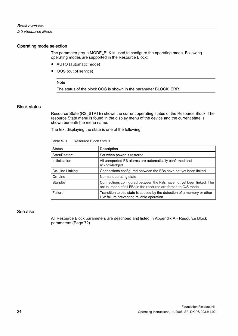
Operating mode selection The parameter group MODE_BLK is used to configure the operating mode. Following operating modes are supported in the Resource Block: ● AUTO (automatic mode) ● OOS (out of service)
Note The status of the block OOS is shown in the parameter BLOCK_ERR.
Block status Resource State (RS_STATE) shows the current operating status of the Resource Block. The resource State menu is found in the display menu of the device and the current state is shown beneath the menu name. The text displaying the state is one of the following:
Table 5- 1 Resource Block Status
Status Description Start/Restart Set when power is restored Initialization All unreported FB alarms are automatically confirmed and
acknowledged On-Line Linking Connections configured between the FBs have not yet been linked On-Line Normal operating state Standby Connections configured between the FBs have not yet been linked. The
actual mode of all FBs in the resource are forced to O/S mode. Failure Transition to this state is caused by the detection of a memory or other
HW failure preventing reliable operation.
See also All Resource Block parameters are described and listed in Appendix A - Resource Block parameters (Page 72).
Block overview 5.4 Transducer blocks
Foundation Fieldbus H1 Operating Instructions, 11/2008, SFI.DK.PS.023.H1.02 25
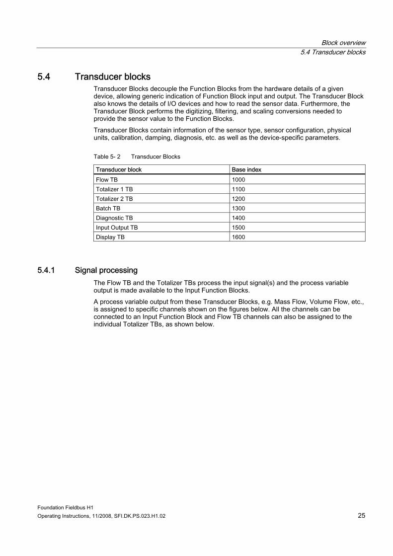
5.4 Transducer blocks Transducer Blocks decouple the Function Blocks from the hardware details of a given device, allowing generic indication of Function Block input and output. The Transducer Block also knows the details of I/O devices and how to read the sensor data. Furthermore, the Transducer Block performs the digitizing, filtering, and scaling conversions needed to provide the sensor value to the Function Blocks. Transducer Blocks contain information of the sensor type, sensor configuration, physical units, calibration, damping, diagnosis, etc. as well as the device-specific parameters.
Table 5- 2 Transducer Blocks
Transducer block Base index Flow TB 1000 Totalizer 1 TB 1100 Totalizer 2 TB 1200 Batch TB 1300 Diagnostic TB 1400 Input Output TB 1500 Display TB 1600
5.4.1 Signal processing The Flow TB and the Totalizer TBs process the input signal(s) and the process variable output is made available to the Input Function Blocks. A process variable output from these Transducer Blocks, e.g. Mass Flow, Volume Flow, etc., is assigned to specific channels shown on the figures below. All the channels can be connected to an Input Function Block and Flow TB channels can also be assigned to the individual Totalizer TBs, as shown below.
Block overview 5.4 Transducer blocks
Foundation Fieldbus H1 26 Operating Instructions, 11/2008, SFI.DK.PS.023.H1.02
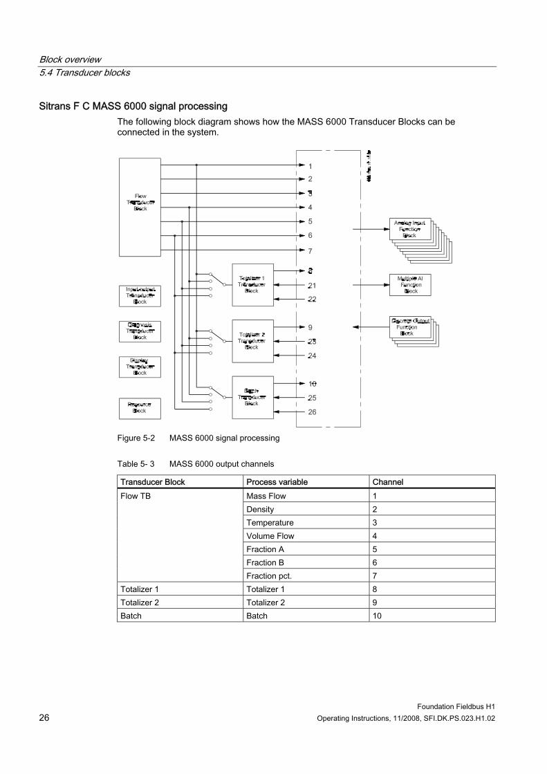
Sitrans F C MASS 6000 signal processing The following block diagram shows how the MASS 6000 Transducer Blocks can be connected in the system.
Figure 5-2 MASS 6000 signal processing
Table 5- 3 MASS 6000 output channels
Transducer Block Process variable Channel Mass Flow 1 Density 2 Temperature 3 Volume Flow 4 Fraction A 5 Fraction B 6
Flow TB
Fraction pct. 7 Totalizer 1 Totalizer 1 8 Totalizer 2 Totalizer 2 9 Batch Batch 10
Block overview 5.4 Transducer blocks
Foundation Fieldbus H1 Operating Instructions, 11/2008, SFI.DK.PS.023.H1.02 27
Table 5- 4 MASS 6000 input channels
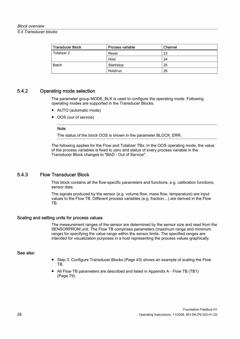
Transducer Block Process variable Channel Reset 21 Totalizer 1 Hold 22 Reset 23 Totalizer 2 Hold 24 Start/stop 25 Batch Hold/run 26
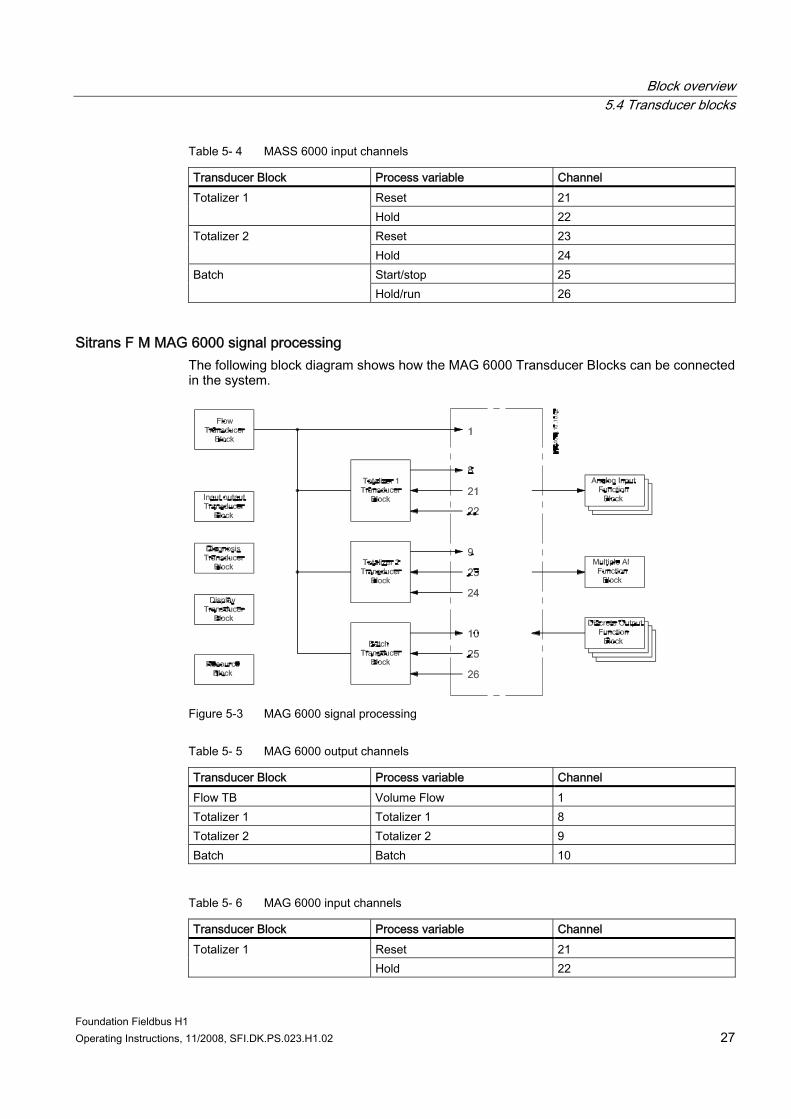
Sitrans F M MAG 6000 signal processing The following block diagram shows how the MAG 6000 Transducer Blocks can be connected in the system.
Figure 5-3 MAG 6000 signal processing
Table 5- 5 MAG 6000 output channels
Transducer Block Process variable Channel Flow TB Volume Flow 1 Totalizer 1 Totalizer 1 8 Totalizer 2 Totalizer 2 9 Batch Batch 10
Table 5- 6 MAG 6000 input channels
Transducer Block Process variable Channel Reset 21 Totalizer 1 Hold 22
Block overview 5.4 Transducer blocks
Foundation Fieldbus H1 28 Operating Instructions, 11/2008, SFI.DK.PS.023.H1.02
Transducer Block Process variable Channel Reset 23 Totalizer 2 Hold 24 Start/stop 25 Batch Hold/run 26
5.4.2 Operating mode selection The parameter group MODE_BLK is used to configure the operating mode. Following operating modes are supported in the Transducer Blocks: ● AUTO (automatic mode) ● OOS (out of service)
Note The status of the block OOS is shown in the parameter BLOCK_ERR.
The following applies for the Flow and Totalizer TBs: In the OOS operating mode, the value of the process variables is fixed to zero and status of every process variable in the Transducer Block changes to "BAD - Out of Service".
5.4.3 Flow Transducer Block This block contains all the flow-specific parameters and functions, e.g. calibration functions, sensor data. The signals produced by the sensor (e.g. volume flow, mass flow, temperature) are input values to the Flow TB. Different process variables (e.g. fraction…) are derived in the Flow TB.
Scaling and setting units for process values The measurement ranges of the sensor are determined by the sensor size and read from the SENSORPROM unit. The Flow TB comprises parameters (maximum range and minimum range) for specifying the value range within the sensor limits. The specified ranges are intended for visualization purposes in a host representing the process values graphically.
See also ● Step 3: Configure Transducer Blocks (Page 43) shows an example of scaling the Flow
TB. ● All Flow TB parameters are described and listed in Appendix A - Flow TB (TB1)
(Page 79).
Block overview 5.4 Transducer blocks
Foundation Fieldbus H1 Operating Instructions, 11/2008, SFI.DK.PS.023.H1.02 29
5.4.4 Totalizer Transducer Blocks Totalizer 1 TB and Totalizer 2 TB contain all parameters for configuring and operating Totalizer 1 and Totalizer 2.
Configuring the Totalizer Totalizer TBs can be configured to totalize process values comprised in the Flow TB: ● In SITRANS F M MAG 6000 the volume flow from the Flow TB can be totalized. ● For SITRANS F C MASS 6000 either Mass Flow, Volume Flow, Fraction A or Fraction B
coming from Flow TB can be totalized. The selection of the process value to be totalized in SITRANS F C MASS 6000 is made in the Totalizer TBs (parameter TOTALIZER_1_SELECTION, index 15).
Operating the Totalizer The Totalizer TBs are controlled from higher level process control system via Discrete Output FBs. The Totalizer can be started, stopped, held and continued.
Note Channels between the Discrete Output FB and the Totalizer TB must be assigned in order to control the Totalizer TB.
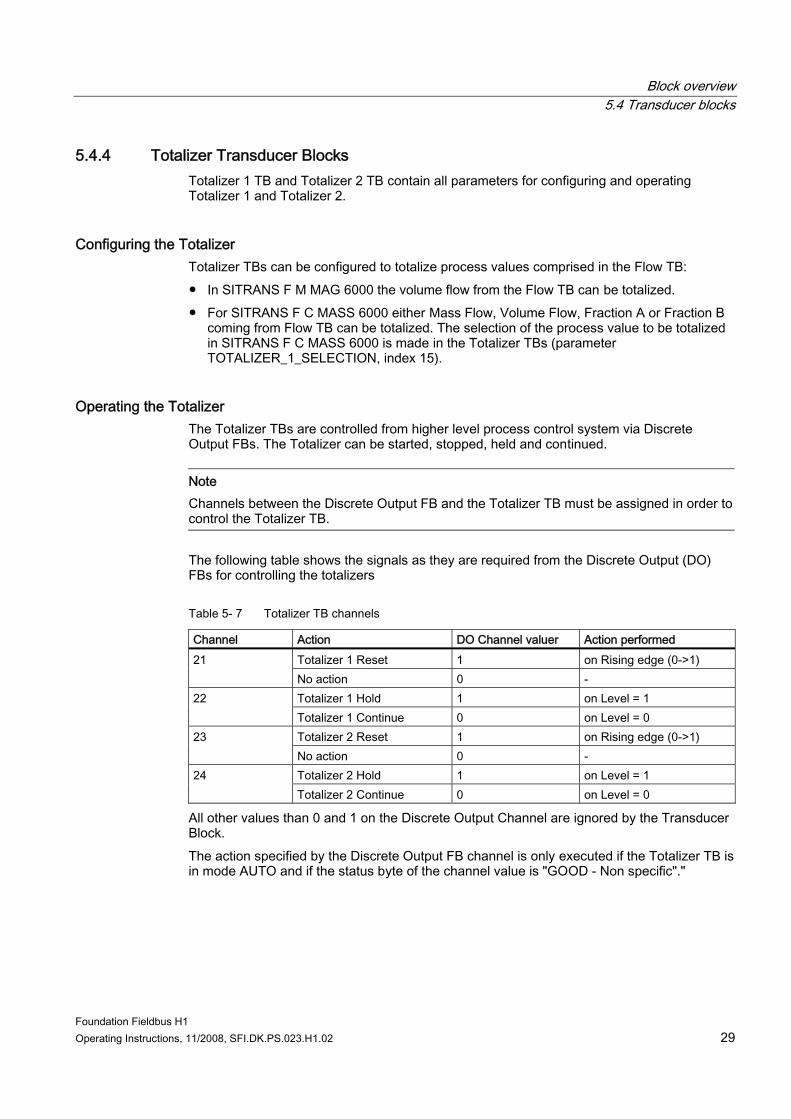
The following table shows the signals as they are required from the Discrete Output (DO) FBs for controlling the totalizers
Table 5- 7 Totalizer TB channels
Channel Action DO Channel valuer Action performed Totalizer 1 Reset 1 on Rising edge (0->1) 21 No action 0 - Totalizer 1 Hold 1 on Level = 1 22 Totalizer 1 Continue 0 on Level = 0 Totalizer 2 Reset 1 on Rising edge (0->1) 23 No action 0 - Totalizer 2 Hold 1 on Level = 1 24 Totalizer 2 Continue 0 on Level = 0
All other values than 0 and 1 on the Discrete Output Channel are ignored by the Transducer Block. The action specified by the Discrete Output FB channel is only executed if the Totalizer TB is in mode AUTO and if the status byte of the channel value is "GOOD - Non specific"."
Block overview 5.4 Transducer blocks
Foundation Fieldbus H1 30 Operating Instructions, 11/2008, SFI.DK.PS.023.H1.02
Dependency between Totalizer 2 TB and Batch TB Totalizer 2 TB and Batch TB cannot be used simultaneously. In order to use Totalizer 2 the batch functionality must be deactivated (factory default setting is batch = deactivated).
Note In order to use Totalizer 2, do not set digital output (or relay output for MAG 6000) to Batch in the Input/Output TB. The process value for Totalizer 2 will show "BAD - device failure" if the block is in AUTO mode and the Batch functionality is activated.
See also ● Step 3 in the step by step commissioning guide "Configure Transducer Blocks" shows an
example of configuring Totalizer1. ● The configuration of the Discrete Output FB is described in chapter 6.7.3: "Discrete
Output Function Blocks (Page 37)" ● All Totalizer 1 TB and Totalizer 2 TB parameters are described and listed in Appendix A -
Totalizer 1 TB and Totalizer 2 TB parameter tables (Page 90).
5.4.5 Batch Transducer Block The Batch TB contains parameters for configuring and operating the Batch functionality. The Batch functionality can be used for controlling the Digital Output or the Relay Output (only MAG 6000). The Batch must be activated in Digital Output or Relay Output settings within the Input/Output TB.
Configuring Batch Batch TB comprises parameters for configuring the batch functionality of SITRANS F transmitters: ● In SITRANS F M MAG 6000 the volume flow from the Flow TB can be batched. ● For SITRANS F C MASS 6000 either Mass Flow, Volume Flow, Fraction A or Fraction B
coming from Flow TB can be batched. The selection of the process value to be batched in SITRANS F C MASS 6000 is made in the Batch TB (BATCH_SELECTION, index 15).
Note Batch TB and Totalizer 2 TB cannot be used simultaneously. The process value for batch will show "BAD - DeviceFailure" if the block is in AUTO mode and Batch has not been activated from the Input/Output TB. The interdependence of Batch TB and Totalizer 2 TB is described in Totalizer Transducer Blocks (Page 29)
Block overview 5.4 Transducer blocks
Foundation Fieldbus H1 Operating Instructions, 11/2008, SFI.DK.PS.023.H1.02 31
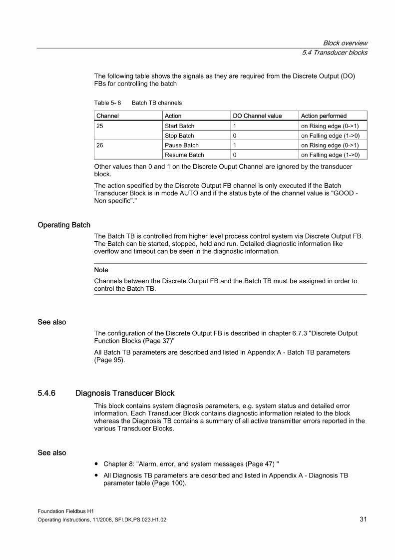
The following table shows the signals as they are required from the Discrete Output (DO) FBs for controlling the batch
Table 5- 8 Batch TB channels
Channel Action DO Channel value Action performed Start Batch 1 on Rising edge (0->1) 25 Stop Batch 0 on Falling edge (1->0) Pause Batch 1 on Rising edge (0->1) 26 Resume Batch 0 on Falling edge (1->0)
Other values than 0 and 1 on the Discrete Ouput Channel are ignored by the transducer block. The action specified by the Discrete Output FB channel is only executed if the Batch Transducer Block is in mode AUTO and if the status byte of the channel value is "GOOD - Non specific"."
Operating Batch The Batch TB is controlled from higher level process control system via Discrete Output FB. The Batch can be started, stopped, held and run. Detailed diagnostic information like overflow and timeout can be seen in the diagnostic information.
Note Channels between the Discrete Output FB and the Batch TB must be assigned in order to control the Batch TB.
See also The configuration of the Discrete Output FB is described in chapter 6.7.3 "Discrete Output Function Blocks (Page 37)" All Batch TB parameters are described and listed in Appendix A - Batch TB parameters (Page 95).
5.4.6 Diagnosis Transducer Block This block contains system diagnosis parameters, e.g. system status and detailed error information. Each Transducer Block contains diagnostic information related to the block whereas the Diagnosis TB contains a summary of all active transmitter errors reported in the various Transducer Blocks.
See also ● Chapter 8: "Alarm, error, and system messages (Page 47) " ● All Diagnosis TB parameters are described and listed in Appendix A - Diagnosis TB
parameter table (Page 100).
Block overview 5.5 Function blocks
Foundation Fieldbus H1 32 Operating Instructions, 11/2008, SFI.DK.PS.023.H1.02
5.4.7 Input/output Transducer Block Besides the FF communication interface, the transmitter offers a series of electrical interfaces, i.e. Digital Input, Digital Output, Relay Output and Current Output. The Transducer Block contains all the Input and Output specific parameters
Dependency between inputs and outputs settings Batch can be controlled (started and stopped) via the digital input of the device. When digital input is set to batch control, digital output (or relay output in MAG 6000) is automatically set to batch. If batch is disabled on the output(s), batch is deactivated on digital input.
See also All Input / Output TB parameters are described and listed in Appendix A - Input / Output TB parameters (Page 102).
5.4.8 Display Transducer Block This block contains all parameters for configuring the Local User Interface of the device.
Configure Display The Display TB can configure the Local User Interface (LUI) to show different process values or text in different lines. Process value unit and location of decimal point can be changed.
Note Local User Interface units can be changed independently of the unit in other Transducer Blocks (e.g. the LUI volume flow unit can be configured independently of the Flow TB volume flow unit).
All Display TB parameters are described and listed in Appendix A - Display TB parameters (Page 100).
5.5 Function blocks Function Blocks specify the automation functions of the device and compose parameters and algorithms that control the functionality of the application system. Function blocks are used as building blocks in defining the monitoring and control application.
Overview The output values of the Function Blocks are made available to other Function Blocks for further processing. Individual Function Blocks can be linked to each other. 20 Function Blocks are available in the USM-II FF module:
Block overview 5.5 Function blocks
Foundation Fieldbus H1 Operating Instructions, 11/2008, SFI.DK.PS.023.H1.02 33
● 9 Analog Input FBs [Only 3 for MAG6000] ● 2 Integrator FBs ● 4 Discrete Output FBs ● 1 PID FB ● 1 Arithmetic FB ● 1 Multiple Analog Input FB ● 1 Signal Characterizer FB ● 1 Input Selector FB
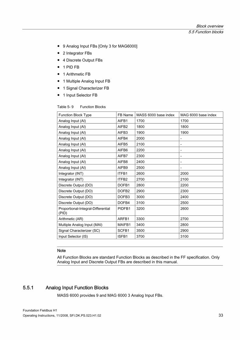
Table 5- 9 Function Blocks
Function Block Type FB Name MASS 6000 base index MAG 6000 base index Analog Input (AI) AIFB1 1700 1700 Analog Input (AI) AIFB2 1800 1800 Analog Input (AI) AIFB3 1900 1900 Analog Input (AI) AIFB4 2000 - Analog Input (AI) AIFB5 2100 - Analog Input (AI) AIFB6 2200 - Analog Input (AI) AIFB7 2300 - Analog Input (AI) AIFB8 2400 - Analog Input (AI) AIFB9 2500 - Integrator (INT) ITFB1 2600 2000 Integrator (INT) ITFB2 2700 2100 Discrete Output (DO) DOFB1 2800 2200 Discrete Output (DO) DOFB2 2900 2300 Discrete Output (DO) DOFB3 3000 2400 Discrete Output (DO) DOFB4 3100 2500 Proportional-Integral-Differential (PID)
PIDFB1 3200 2600
Arithmetic (AR) ARFB1 3300 2700 Multiple Analog Input (MAI) MAIFB1 3400 2800 Signal Characterizer (SC) SCFB1 3500 2900 Input Selector (IS) ISFB1 3700 3100
Note All Function Blocks are standard Function Blocks as described in the FF specification. Only Analog Input and Discrete Output FBs are described in this manual.
5.5.1 Analog Input Function Blocks MASS 6000 provides 9 and MAG 6000 3 Analog Input FBs.
Block overview 5.5 Function blocks
Foundation Fieldbus H1 34 Operating Instructions, 11/2008, SFI.DK.PS.023.H1.02
The Analog Input FB is a universal interface that puts the process variable, including status information, on the fieldbus. It ensures that all devices, irrespective of type and manufacturer, publish their information in exactly the same way. The Analog Input FB processes the signal output from the Transducer Block and makes the signal available for the PLC or other Function Blocks. The USMII FF module provides more than one process value and thereby more than one Analog Input FB (one Analog Input FB for each process value): ● 9 Analog Input FB instances for MASS 6000 ● 3 Analog Input FB instances for MAG 6000
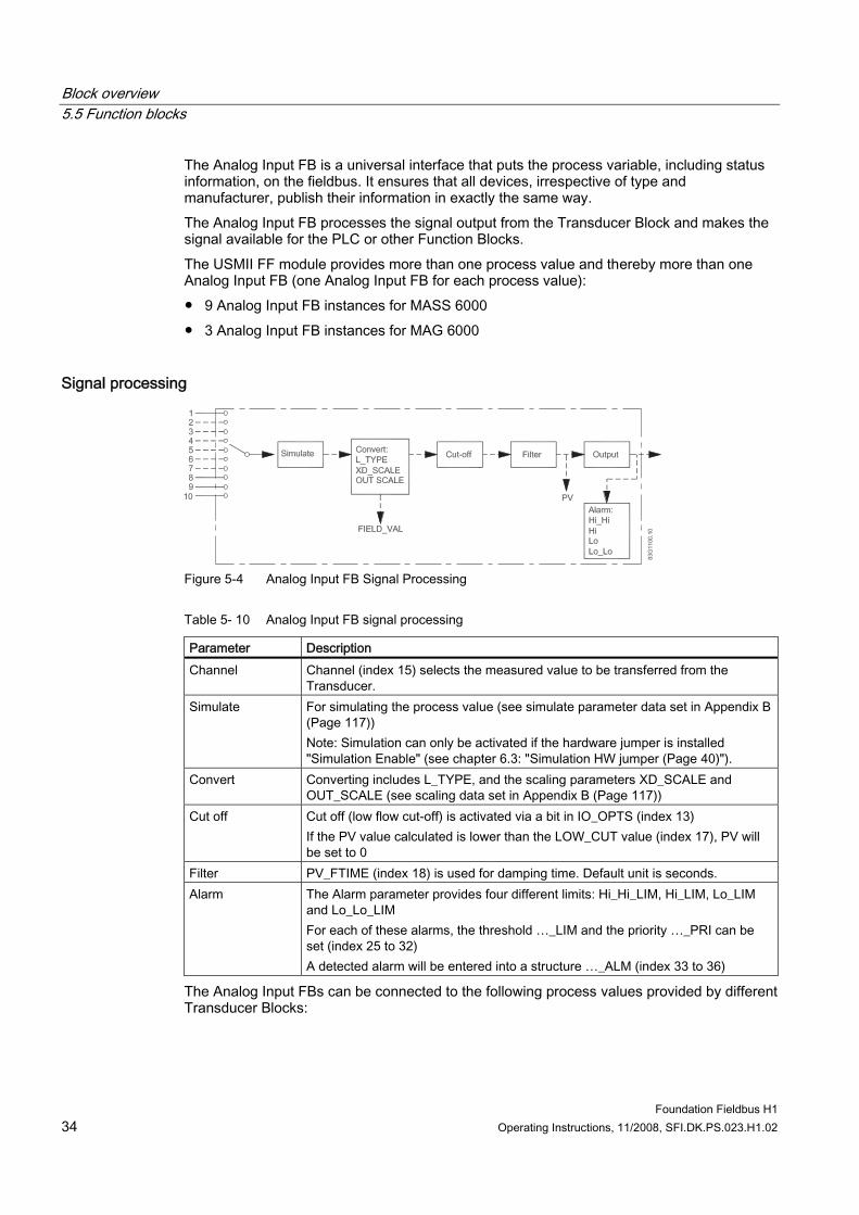
Signal processing
Figure 5-4 Analog Input FB Signal Processing
Table 5- 10 Analog Input FB signal processing
Parameter Description Channel Channel (index 15) selects the measured value to be transferred from the
Transducer. Simulate For simulating the process value (see simulate parameter data set in Appendix B
(Page 117)) Note: Simulation can only be activated if the hardware jumper is installed "Simulation Enable" (see chapter 6.3: "Simulation HW jumper (Page 40)").
Convert Converting includes L_TYPE, and the scaling parameters XD_SCALE and OUT_SCALE (see scaling data set in Appendix B (Page 117))
Cut off Cut off (low flow cut-off) is activated via a bit in IO_OPTS (index 13) If the PV value calculated is lower than the LOW_CUT value (index 17), PV will be set to 0
Filter PV_FTIME (index 18) is used for damping time. Default unit is seconds. Alarm The Alarm parameter provides four different limits: Hi_Hi_LIM, Hi_LIM, Lo_LIM
and Lo_Lo_LIM For each of these alarms, the threshold …_LIM and the priority …_PRI can be set (index 25 to 32) A detected alarm will be entered into a structure …_ALM (index 33 to 36)
The Analog Input FBs can be connected to the following process values provided by different Transducer Blocks:
Block overview 5.5 Function blocks
Foundation Fieldbus H1 Operating Instructions, 11/2008, SFI.DK.PS.023.H1.02 35
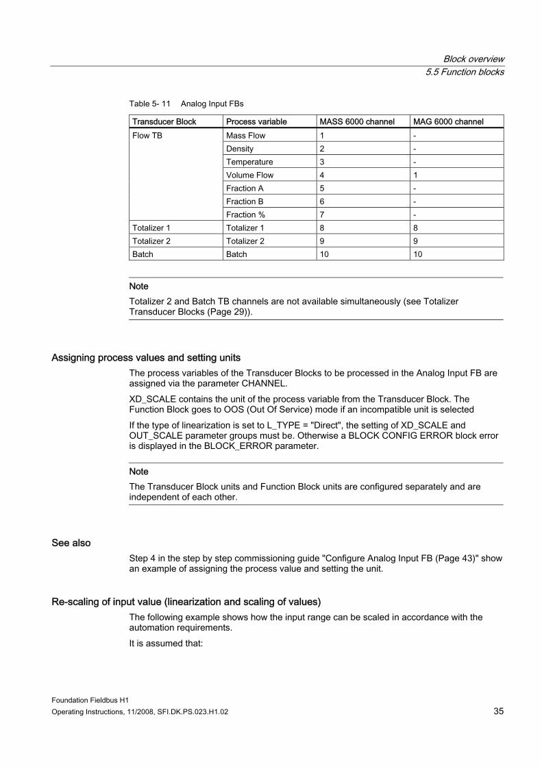
Table 5- 11 Analog Input FBs
Transducer Block Process variable MASS 6000 channel MAG 6000 channel Mass Flow 1 - Density 2 - Temperature 3 - Volume Flow 4 1 Fraction A 5 - Fraction B 6 -
Flow TB
Fraction % 7 - Totalizer 1 Totalizer 1 8 8 Totalizer 2 Totalizer 2 9 9 Batch Batch 10 10
Note Totalizer 2 and Batch TB channels are not available simultaneously (see Totalizer Transducer Blocks (Page 29)).
Assigning process values and setting units The process variables of the Transducer Blocks to be processed in the Analog Input FB are assigned via the parameter CHANNEL. XD_SCALE contains the unit of the process variable from the Transducer Block. The Function Block goes to OOS (Out Of Service) mode if an incompatible unit is selected If the type of linearization is set to L_TYPE = "Direct", the setting of XD_SCALE and OUT_SCALE parameter groups must be. Otherwise a BLOCK CONFIG ERROR block error is displayed in the BLOCK_ERROR parameter.
Note The Transducer Block units and Function Block units are configured separately and are independent of each other.
See also Step 4 in the step by step commissioning guide "Configure Analog Input FB (Page 43)" show an example of assigning the process value and setting the unit.
Re-scaling of input value (linearization and scaling of values) The following example shows how the input range can be scaled in accordance with the automation requirements. It is assumed that:
Block overview 5.5 Function blocks
Foundation Fieldbus H1 36 Operating Instructions, 11/2008, SFI.DK.PS.023.H1.02
● The system is using MASS 6000 flowmeter measuring massflow. ● The Transducer Block unit is kg/s. ● The measurement range of the sensor is 0 to 800 kg/s. ● The output range to the process control system should be 0 to 100%. Analog Input FB configuration: ● Set: CHANNEL 1 = Mass flow ● Set: L_TYPE = Indirect The process variable "Mass flow" from the Flow Transducer Block is rescaled linearly in the ANALOG INPUT FB via input scaling XD_SCALE to the desired output range OUT_SCALE. ● Parameter group XD_SCALE
– XD_SCALE 0 % = 0 – XD_SCALE 100 % = 800 – XD_SCALE UNIT = kg/s
● Parameter group OUT_SCALE – XD_SCALE 0 % = 0 – XD_SCALE 100 % = 100 – XD_SCALE UNIT = %
The result is that with an input value of, for example, 400 kg/s a value of 50% is output via the parameter OUT.
Setting and detecting limit alarms The limit parameters can be set to detect if the OUT value exceeds or does not reach the defined limit values. The OUT value can have following limits: ● HI_HI_LIM (upper alarm limit) ● HI_LIM (upper pre-warning limit) ● LO_LO_LIM (lower alarm limit) ● LO_LIM (lower pre-warning limit) The fieldbus host system retrieves information about limit violations via the process limit parameters. BLOCK_ALM provides the system status information and ACK_OPTION specifies whether an alarm must be acknowledged via the fieldbus host system. Example: ● HI_HI_LIM = 100% ● HI_LIM = 90% ● LO_LIM = 10% ● LO_LO_LIM = 0 % If massflow = 790 kg/s => HI_ALM will be active and must be acknowledged via the fieldbus host system.
Block overview 5.5 Function blocks
Foundation Fieldbus H1 Operating Instructions, 11/2008, SFI.DK.PS.023.H1.02 37
Simulating Analog Input FBs allow simulation of the input and output of the Function Block: ● The input value of the Function Block can be simulated by specifying the process value in
the parameter group SIMULATE.
Note The simulation of the input value can only be activated if the HW jumper is set to simulation (see chapter 6.3: "Simulation HW jumper (Page 40)")
● Parameter OUT value can be replaced with desired value if block is in MAN mode.
5.5.2 Discrete Output Function Blocks The Discrete Output FB is a universal interface that receives a discrete set point value from the process control or high level Function Blocks to initiate a function in connected Transducer Block. The USMII FF module provides 4 Discrete Output FBs for both MAG 6000 and MASS 6000: ● 4 Discrete Output FB instances for MASS 6000
– DOFB1 base index 2800 – DOFB2 base index 2900 – DOFB3 base index 3000 – DOFB4 base index 3100
● 4 Discrete Output FB instances for MAG 6000 – DOFB1 base index 2200 – DOFB2 base index 2300 – DOFB3 base index 2400 – DOFB4 base index 2500
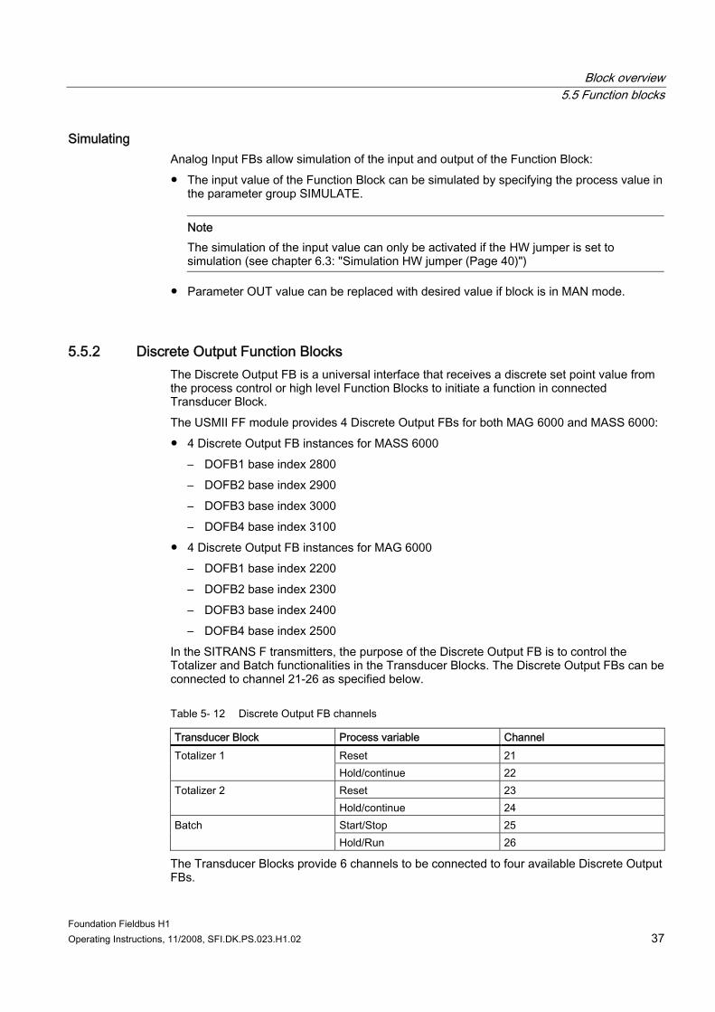
In the SITRANS F transmitters, the purpose of the Discrete Output FB is to control the Totalizer and Batch functionalities in the Transducer Blocks. The Discrete Output FBs can be connected to channel 21-26 as specified below.
Table 5- 12 Discrete Output FB channels
Transducer Block Process variable Channel Reset 21 Totalizer 1 Hold/continue 22 Reset 23 Totalizer 2 Hold/continue 24 Start/Stop 25 Batch Hold/Run 26
The Transducer Blocks provide 6 channels to be connected to four available Discrete Output FBs.

Block overview 5.5 Function blocks
Foundation Fieldbus H1 38 Operating Instructions, 11/2008, SFI.DK.PS.023.H1.02
See also ● Step 5 of the step by step guide to commissioning "Configure discrete output FB
(Page 46)" shows an example of configuring Discrete Output FB. ● Control signal tables in the chapters Totalizer Transducer Blocks (Page 29) and Batch
Transducer Block (Page 30).
Foundation Fieldbus H1 Operating Instructions, 11/2008, SFI.DK.PS.023.H1.02 39
System integration 66.1 Introduction
This chapter provides information on how to integrate MAG 6000 and MASS 6000 in a FF automation and control system. The chapter shows the necessary steps in order to put the system into operation. After finishing the steps, the system is ready to go into normal operation in the FF automation control system.
Transmitter settings All FF settings of the transmitter are stored in the add-on module in a non-volatile memory. All other transmitter settings are stored in the SENSORPROM® memory unit. The storage location of each parameter is specified in the tables in Appendix A (Page 71).
Note If the FF module is replaced, all FF settings must be downloaded from the master to the device.
Device Tag and address The transmitter is shipped with a default device tag containing device name and serial number. Each Foundation Fieldbus device has a unique physical device tag. A device tag is assigned to the device when it is commissioned and it retains the tag in its memory when it is disconnected. All devices are shipped with a temporary address that allows the host to automatically commission the transmitter. The network address is the current device address used by the fieldbus.
6.2 Function check Before proceeding further, make sure that installation and connection have been performed successfully. ● See chapter "Hardware installation (Page 11)" for installation verification. ● See chapter "Connecting (Page 17)" for connection verification. When the function check has been successfully carried out, the device can be switched on.
6.3 Parameter access The parameter access of each block is listed in parameter table (see Appendix A (Page 71)).
System integration 6.4 Simulation HW jumper
Foundation Fieldbus H1 40 Operating Instructions, 11/2008, SFI.DK.PS.023.H1.02
Write protection The device can be set to write protected mode to protect the device from any modification. This is done be setting parameter "Write Lock" in the Resource Block. If write protection is not enabled and the operating mode is set to "Out of servide" (OOS), all write parameters can be accessed without any restriction.
Access from Local User Interface Parameters stored in the SITRANS F transmitter (not in the Fieldbus module) can be accessed through the local display menu. The default password for accessing the "Setup Menu" in the local display can be changed from the manufacturer specific Display TB.
Note Parameters changed via the local user interface are not automatically synchronized/updated in the host, even if feature like "Synchronize database with live device configuration on device access" are applied to AMS Device Manager.
6.4 Simulation HW jumper A hardware switch/jumper is available on the PCB board of the FF module in order to make simulation possible in the Analog Input FBs. ● Jumper installed = Simulation Mode Enabled ● Jumper Not installed = Simulation Mode Disabled The jumper position is also displayed via the resource block within the parameter BLOCK_ERR. "Simulation Mode enabled" makes simulation possible, but does not activate the simulation. Simulation is activated / deactivated within the parameter SIMULATE in the Analog Input FBs or Digital Output FBs.
6.5 Step by step guide to commissioning The commissioning via Foundation Fieldbus can be performed by use of diverse configuration and operation tools from different manufacturers. Some tools, like AMS, are only for configuring device parameters (i.e. Transducer and Resource block parameters) other tools can also program the automation function of the system (i.e. Function blocks). Files for commissioning and network configuration can be downloaded free of charge. The following files are needed for commissioning and network configuration: ● Network Configuration -> CFF file (Common File Format: *.cff) ● Commissioning -> Device description (Device Description: *.sym, *.ffo, *.ff5). The files can be obtained via the Siemens Flow Instruments Support Website (http://support.automation.siemens.com/WW/view/en/17320447/133100)
System integration 6.5 Step by step guide to commissioning
Foundation Fieldbus H1 Operating Instructions, 11/2008, SFI.DK.PS.023.H1.02 41
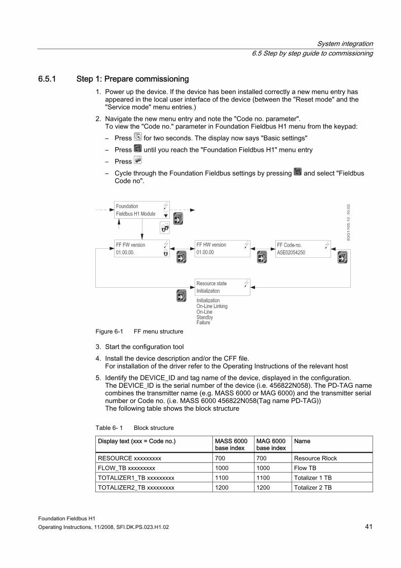
6.5.1 Step 1: Prepare commissioning 1. Power up the device. If the device has been installed correctly a new menu entry has
appeared in the local user interface of the device (between the "Reset mode" and the "Service mode" menu entries.)
2. Navigate the new menu entry and note the "Code no. parameter". To view the "Code no." parameter in Foundation Fieldbus H1 menu from the keypad: – Press for two seconds. The display now says "Basic settings" – Press until you reach the "Foundation Fieldbus H1" menu entry – Press – Cycle through the Foundation Fieldbus settings by pressing and select "Fieldbus
Code no".
Figure 6-1 FF menu structure
3. Start the configuration tool 4. Install the device description and/or the CFF file.
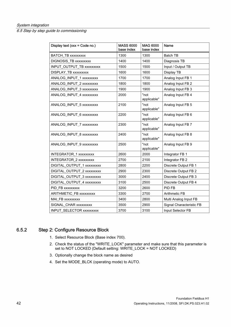
For installation of the driver refer to the Operating Instructions of the relevant host 5. Identify the DEVICE_ID and tag name of the device, displayed in the configuration.
The DEVICE_ID is the serial number of the device (i.e. 456822N058). The PD-TAG name combines the transmitter name (e.g. MASS 6000 or MAG 6000) and the transmitter serial number or Code no. (i.e. MASS 6000 456822N058(Tag name PD-TAG)) The following table shows the block structure
Table 6- 1 Block structure
Display text (xxx = Code no.) MASS 6000 base index
MAG 6000 base index
Name
RESOURCE xxxxxxxxx 700 700 Resource Rlock FLOW_TB xxxxxxxxx 1000 1000 Flow TB TOTALIZER1_TB xxxxxxxxx 1100 1100 Totalizer 1 TB TOTALIZER2_TB xxxxxxxxx 1200 1200 Totalizer 2 TB
System integration 6.5 Step by step guide to commissioning
Foundation Fieldbus H1 42 Operating Instructions, 11/2008, SFI.DK.PS.023.H1.02
Display text (xxx = Code no.) MASS 6000 base index
MAG 6000 base index
Name
BATCH_TB xxxxxxxxx 1300 1300 Batch TB DIGNOSIS_TB xxxxxxxxx 1400 1400 Diagnosis TB INPUT_OUTPUT_TB xxxxxxxxx 1500 1500 Input / Output TB DISPLAY_TB xxxxxxxxx 1600 1600 Display TB ANALOG_INPUT_1 xxxxxxxxx 1700 1700 Analog Input FB 1 ANALOG_INPUT_2 xxxxxxxxx 1800 1800 Analog Input FB 2 ANALOG_INPUT_3 xxxxxxxxx 1900 1900 Analog Input FB 3 ANALOG_INPUT_4 xxxxxxxxx 2000 "not
applicable" Analog Input FB 4
ANALOG_INPUT_5 xxxxxxxxx 2100 "not applicable"
Analog Input FB 5
ANALOG_INPUT_6 xxxxxxxxx 2200 "not applicable"
Analog Input FB 6
ANALOG_INPUT_7 xxxxxxxxx 2300 "not applicable"
Analog Input FB 7
ANALOG_INPUT_8 xxxxxxxxx 2400 "not applicable"
Analog Input FB 8
ANALOG_INPUT_9 xxxxxxxxx 2500 "not applicable"
Analog Input FB 9
INTEGRATOR_1 xxxxxxxxx 2600 2000 Integrator FB 1 INTEGRATOR_2 xxxxxxxxx 2700 2100 Integrator FB 2 DIGITAL_OUTPUT_1 xxxxxxxxx 2800 2200 Discrete Output FB 1 DIGITAL_OUTPUT_2 xxxxxxxxx 2900 2300 Discrete Output FB 2 DIGITAL_OUTPUT_3 xxxxxxxxx 3000 2400 Discrete Output FB 3 DIGITAL_OUTPUT_4 xxxxxxxxx 3100 2500 Discrete Output FB 4 PID_FB xxxxxxxxx 3200 2600 PID FB ARITHMETIC_FB xxxxxxxxx 3300 2700 Arithmetic FB MAI_FB xxxxxxxxx 3400 2800 Multi Analog Input FB SIGNAL_CHAR xxxxxxxxx 3500 2900 Signal Characteristic FB INPUT_SELECTOR xxxxxxxxx 3700 3100 Input Selector FB
6.5.2 Step 2: Configure Resource Block 1. Select Resource Block (Base index 700). 2. Check the status of the "WRITE_LOCK" parameter and make sure that this parameter is
set to NOT LOCKED (Default setting: WRITE_LOCK = NOT LOCKED) 3. Optionally change the block name as desired 4. Set the MODE_BLCK (operating mode) to AUTO.
System integration 6.5 Step by step guide to commissioning
Foundation Fieldbus H1 Operating Instructions, 11/2008, SFI.DK.PS.023.H1.02 43
6.5.3 Step 3: Configure Transducer Blocks
Configure Flow TB 1. Select Flow Transducer Block (Base index 1000). 2. Change the block name if desired 3. Configure the Flow TB parameter for your application. 4. Set the Flow TB to auto (MODE_BLK = AUTO).
Configure Totalizer 1 TB 1. Select Totalizer 1 Transducer block (base index 1100) 2. Change the block name if desired 3. Configure the Totalizer 1 TB parameter for your application.
– Select process value (only MASS 6000, Volume Flow is always selected for MAG 6000)
– Configure the process value, direction and unit 4. Set the Totalizer 1 TB to auto (MODE_BLK = AUTO).
See also Totalizer Transducer Blocks (Page 29) Flow Transducer Block (Page 28)
6.5.4 Step 4: Configure Analog Input FB 1. Select the Analog Input Function Block (AI1) (base index 1700)
The Foundation Fieldbus module provides 3 Analog Input FB instances for MAG 6000 and 9 Analog Input FB instances for MASS 6000. Each process variable output from the Transducer Blocks can be assigned individually to the Analog Input FBs. The following steps describe configuration of Analog Input FB 1 (AI1) in a MASS 6000 transmitter.
2. Change the block name if desired 3. Set the AI1 block to Out Of Service (MODE_BLK = OOS).
System integration 6.5 Step by step guide to commissioning
Foundation Fieldbus H1 44 Operating Instructions, 11/2008, SFI.DK.PS.023.H1.02
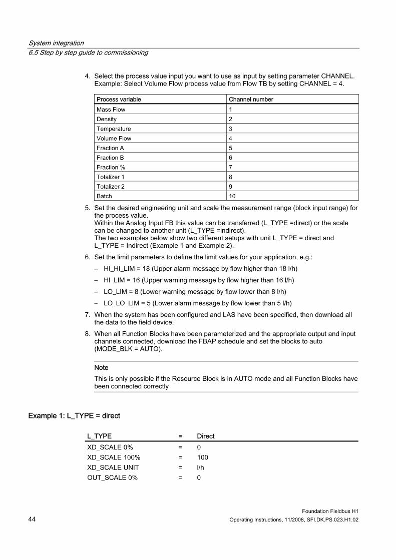
4. Select the process value input you want to use as input by setting parameter CHANNEL. Example: Select Volume Flow process value from Flow TB by setting CHANNEL = 4.
Process variable Channel number Mass Flow 1 Density 2 Temperature 3 Volume Flow 4 Fraction A 5 Fraction B 6 Fraction % 7 Totalizer 1 8 Totalizer 2 9 Batch 10
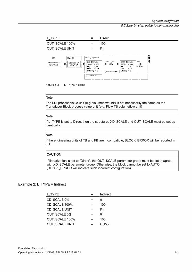
5. Set the desired engineering unit and scale the measurement range (block input range) for the process value. Within the Analog Input FB this value can be transferred (L_TYPE =direct) or the scale can be changed to another unit (L_TYPE =indirect). The two examples below show two different setups with unit L_TYPE = direct and L_TYPE = Indirect (Example 1 and Example 2).
6. Set the limit parameters to define the limit values for your application, e.g.: – HI_HI_LIM = 18 (Upper alarm message by flow higher than 18 l/h) – HI_LIM = 16 (Upper warning message by flow higher than 16 l/h) – LO_LIM = 8 (Lower warning message by flow lower than 8 l/h) – LO_LO_LIM = 5 (Lower alarm message by flow lower than 5 l/h)
7. When the system has been configured and LAS have been specified, then download all the data to the field device.
8. When all Function Blocks have been parameterized and the appropriate output and input channels connected, download the FBAP schedule and set the blocks to auto (MODE_BLK = AUTO).
Note This is only possible if the Resource Block is in AUTO mode and all Function Blocks have been connected correctly
Example 1: L_TYPE = direct L_TYPE = Direct XD_SCALE 0% = 0 XD_SCALE 100% = 100 XD_SCALE UNIT = l/h OUT_SCALE 0% = 0
System integration 6.5 Step by step guide to commissioning
Foundation Fieldbus H1 Operating Instructions, 11/2008, SFI.DK.PS.023.H1.02 45
L_TYPE = Direct OUT_SCALE 100% = 100 OUT_SCALE UNIT = l/h
Figure 6-2 L_TYPE = direct
Note The LUI process value unit (e.g. volumeflow unit) is not necessarily the same as the Transducer Block process value unit (e.g. Flow TB volumeflow unit)
Note If L_TYPE is set to Direct then the structures XD_SCALE and OUT_SCALE must be set up identically.
Note If the engineering units of TB and FB are incompatible, BLOCK_ERROR will be reported in FB.
CAUTION If linearization is set to "Direct", the OUT_SCALE parameter group must be set to agree with XD_SCALE parameter group. Otherwise, the block cannot be set to AUTO (BLOCK_ERROR will indicate such incorrect configuration).
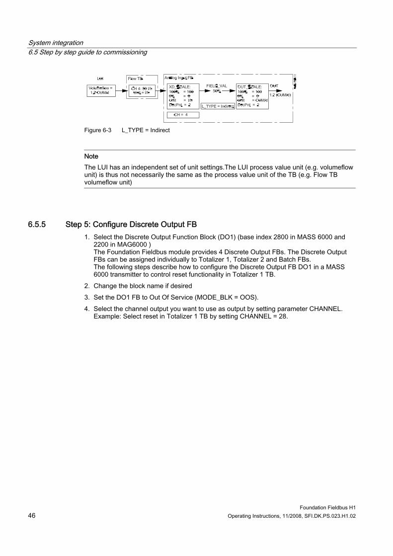
Example 2: L_TYPE = Indirect L_TYPE = Indirect XD_SCALE 0% = 0 XD_SCALE 100% = 100 XD_SCALE UNIT = l/h OUT_SCALE 0% = 0 OUT_SCALE 100% = 100 OUT_SCALE UNIT = CUM/d
System integration 6.5 Step by step guide to commissioning
Foundation Fieldbus H1 46 Operating Instructions, 11/2008, SFI.DK.PS.023.H1.02
Figure 6-3 L_TYPE = Indirect
Note The LUI has an independent set of unit settings.The LUI process value unit (e.g. volumeflow unit) is thus not necessarily the same as the process value unit of the TB (e.g. Flow TB volumeflow unit)
6.5.5 Step 5: Configure Discrete Output FB 1. Select the Discrete Output Function Block (DO1) (base index 2800 in MASS 6000 and
2200 in MAG6000 ) The Foundation Fieldbus module provides 4 Discrete Output FBs. The Discrete Output FBs can be assigned individually to Totalizer 1, Totalizer 2 and Batch FBs. The following steps describe how to configure the Discrete Output FB DO1 in a MASS 6000 transmitter to control reset functionality in Totalizer 1 TB.
2. Change the block name if desired 3. Set the DO1 FB to Out Of Service (MODE_BLK = OOS). 4. Select the channel output you want to use as output by setting parameter CHANNEL.
Example: Select reset in Totalizer 1 TB by setting CHANNEL = 28.
Foundation Fieldbus H1 Operating Instructions, 11/2008, SFI.DK.PS.023.H1.02 47
Alarm, error, and system messages 77.1 Introduction
This chapter describes the diagnostic structure of the USMII FF module used with Sitrans F C MASS 6000 or Sitrans F M MAG 6000 transmitters.
Diagnostic overview The device alarm and error status are displayed via the following parameters: ● Block errors (BLOCK_ERR) ● Block alarms (BLOCK_ALARM) ● Detail error information (DETAILED_ERROR_INFO)
Note MODE_BLK must be set to AUTO to enable device alarms and error status.
Note BLOCK_ERR and BLOCK_ALARM parameters are standard block parameters in accordance with the Foundation Fieldbus specification but DETAILED_ERROR_INFO includes device specific errors.
7.2 Block errors and block alarms
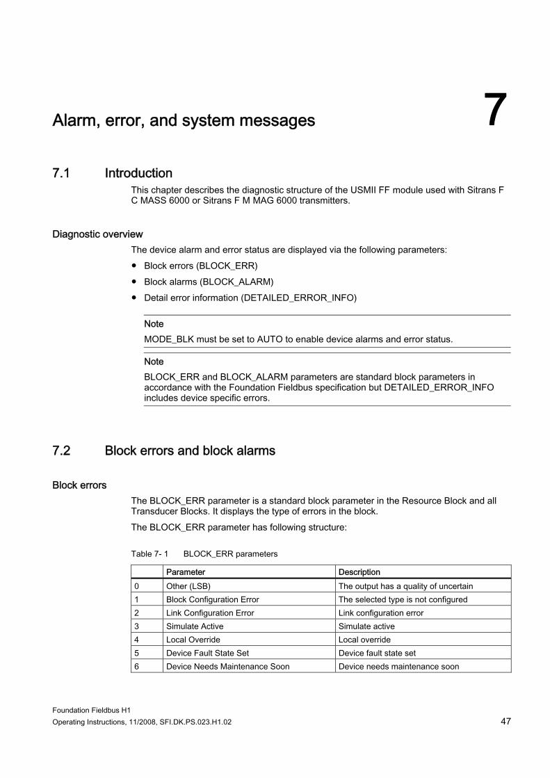
Block errors The BLOCK_ERR parameter is a standard block parameter in the Resource Block and all Transducer Blocks. It displays the type of errors in the block. The BLOCK_ERR parameter has following structure:
Table 7- 1 BLOCK_ERR parameters
Parameter Description 0 Other (LSB) The output has a quality of uncertain 1 Block Configuration Error The selected type is not configured 2 Link Configuration Error Link configuration error 3 Simulate Active Simulate active 4 Local Override Local override 5 Device Fault State Set Device fault state set 6 Device Needs Maintenance Soon Device needs maintenance soon
Alarm, error, and system messages 7.3 Detailed error information
Foundation Fieldbus H1 48 Operating Instructions, 11/2008, SFI.DK.PS.023.H1.02
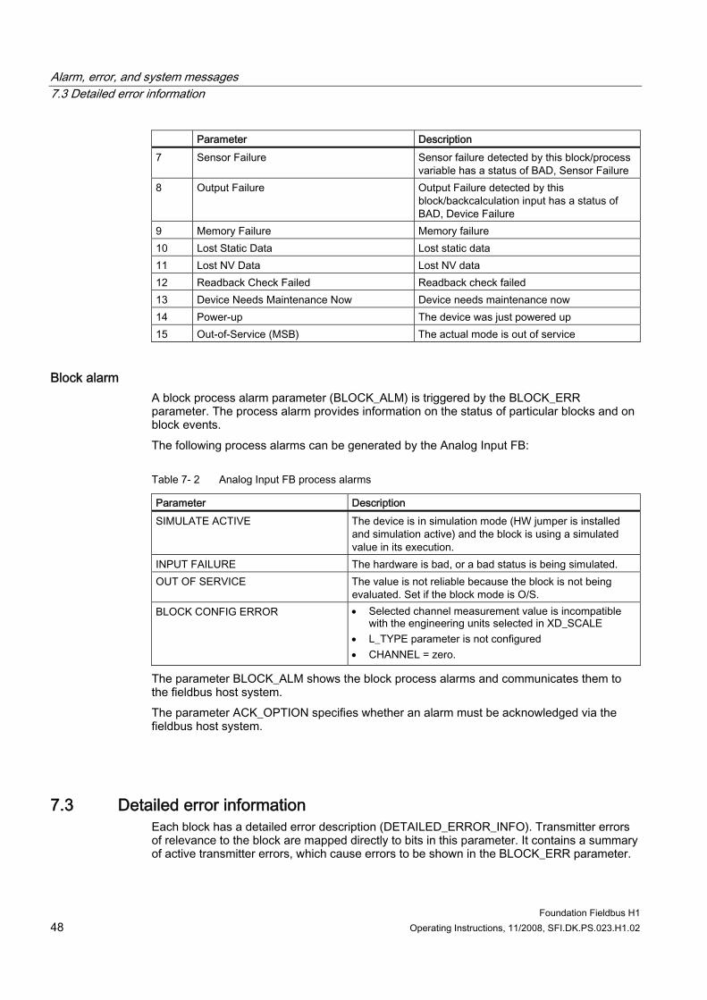
Parameter Description 7 Sensor Failure Sensor failure detected by this block/process
variable has a status of BAD, Sensor Failure 8 Output Failure Output Failure detected by this
block/backcalculation input has a status of BAD, Device Failure
9 Memory Failure Memory failure 10 Lost Static Data Lost static data 11 Lost NV Data Lost NV data 12 Readback Check Failed Readback check failed 13 Device Needs Maintenance Now Device needs maintenance now 14 Power-up The device was just powered up 15 Out-of-Service (MSB) The actual mode is out of service
Block alarm A block process alarm parameter (BLOCK_ALM) is triggered by the BLOCK_ERR parameter. The process alarm provides information on the status of particular blocks and on block events. The following process alarms can be generated by the Analog Input FB:
Table 7- 2 Analog Input FB process alarms
Parameter Description SIMULATE ACTIVE The device is in simulation mode (HW jumper is installed
and simulation active) and the block is using a simulated value in its execution.
INPUT FAILURE The hardware is bad, or a bad status is being simulated. OUT OF SERVICE The value is not reliable because the block is not being
evaluated. Set if the block mode is O/S. BLOCK CONFIG ERROR • Selected channel measurement value is incompatible
with the engineering units selected in XD_SCALE • L_TYPE parameter is not configured • CHANNEL = zero.
The parameter BLOCK_ALM shows the block process alarms and communicates them to the fieldbus host system. The parameter ACK_OPTION specifies whether an alarm must be acknowledged via the fieldbus host system.
7.3 Detailed error information Each block has a detailed error description (DETAILED_ERROR_INFO). Transmitter errors of relevance to the block are mapped directly to bits in this parameter. It contains a summary of active transmitter errors, which cause errors to be shown in the BLOCK_ERR parameter.
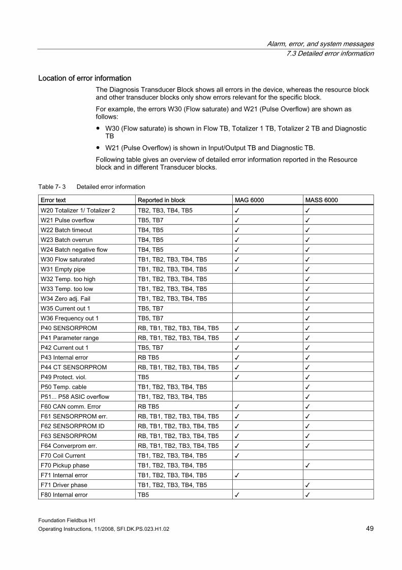
Alarm, error, and system messages 7.3 Detailed error information
Foundation Fieldbus H1 Operating Instructions, 11/2008, SFI.DK.PS.023.H1.02 49
Location of error information The Diagnosis Transducer Block shows all errors in the device, whereas the resource block and other transducer blocks only show errors relevant for the specific block. For example, the errors W30 (Flow saturate) and W21 (Pulse Overflow) are shown as follows: ● W30 (Flow saturate) is shown in Flow TB, Totalizer 1 TB, Totalizer 2 TB and Diagnostic
TB ● W21 (Pulse Overflow) is shown in Input/Output TB and Diagnostic TB. Following table gives an overview of detailed error information reported in the Resource block and in different Transducer blocks.
Table 7- 3 Detailed error information
Error text Reported in block MAG 6000 MASS 6000 W20 Totalizer 1/ Totalizer 2 TB2, TB3, TB4, TB5 ✓ ✓ W21 Pulse overflow TB5, TB7 ✓ ✓ W22 Batch timeout TB4, TB5 ✓ ✓ W23 Batch overrun TB4, TB5 ✓ ✓ W24 Batch negative flow TB4, TB5 ✓ ✓ W30 Flow saturated TB1, TB2, TB3, TB4, TB5 ✓ ✓ W31 Empty pipe TB1, TB2, TB3, TB4, TB5 ✓ ✓ W32 Temp. too high TB1, TB2, TB3, TB4, TB5 ✓ W33 Temp. too low TB1, TB2, TB3, TB4, TB5 ✓ W34 Zero adj. Fail TB1, TB2, TB3, TB4, TB5 ✓ W35 Current out 1 TB5, TB7 ✓ W36 Frequency out 1 TB5, TB7 ✓ P40 SENSORPROM RB, TB1, TB2, TB3, TB4, TB5 ✓ ✓ P41 Parameter range RB, TB1, TB2, TB3, TB4, TB5 ✓ ✓ P42 Current out 1 TB5, TB7 ✓ ✓ P43 Internal error RB TB5 ✓ ✓ P44 CT SENSORPROM RB, TB1, TB2, TB3, TB4, TB5 ✓ ✓ P49 Protect. viol. TB5 ✓ ✓ P50 Temp. cable TB1, TB2, TB3, TB4, TB5 ✓ P51... P58 ASIC overflow TB1, TB2, TB3, TB4, TB5 ✓ F60 CAN comm. Error RB TB5 ✓ ✓ F61 SENSORPROM err. RB, TB1, TB2, TB3, TB4, TB5 ✓ ✓ F62 SENSORPROM ID RB, TB1, TB2, TB3, TB4, TB5 ✓ ✓ F63 SENSORPROM RB, TB1, TB2, TB3, TB4, TB5 ✓ ✓ F64 Converprom err. RB, TB1, TB2, TB3, TB4, TB5 ✓ ✓ F70 Coil Current TB1, TB2, TB3, TB4, TB5 ✓ F70 Pickup phase TB1, TB2, TB3, TB4, TB5 ✓ F71 Internal error TB1, TB2, TB3, TB4, TB5 ✓ F71 Driver phase TB1, TB2, TB3, TB4, TB5 ✓ F80 Internal error TB5 ✓ ✓
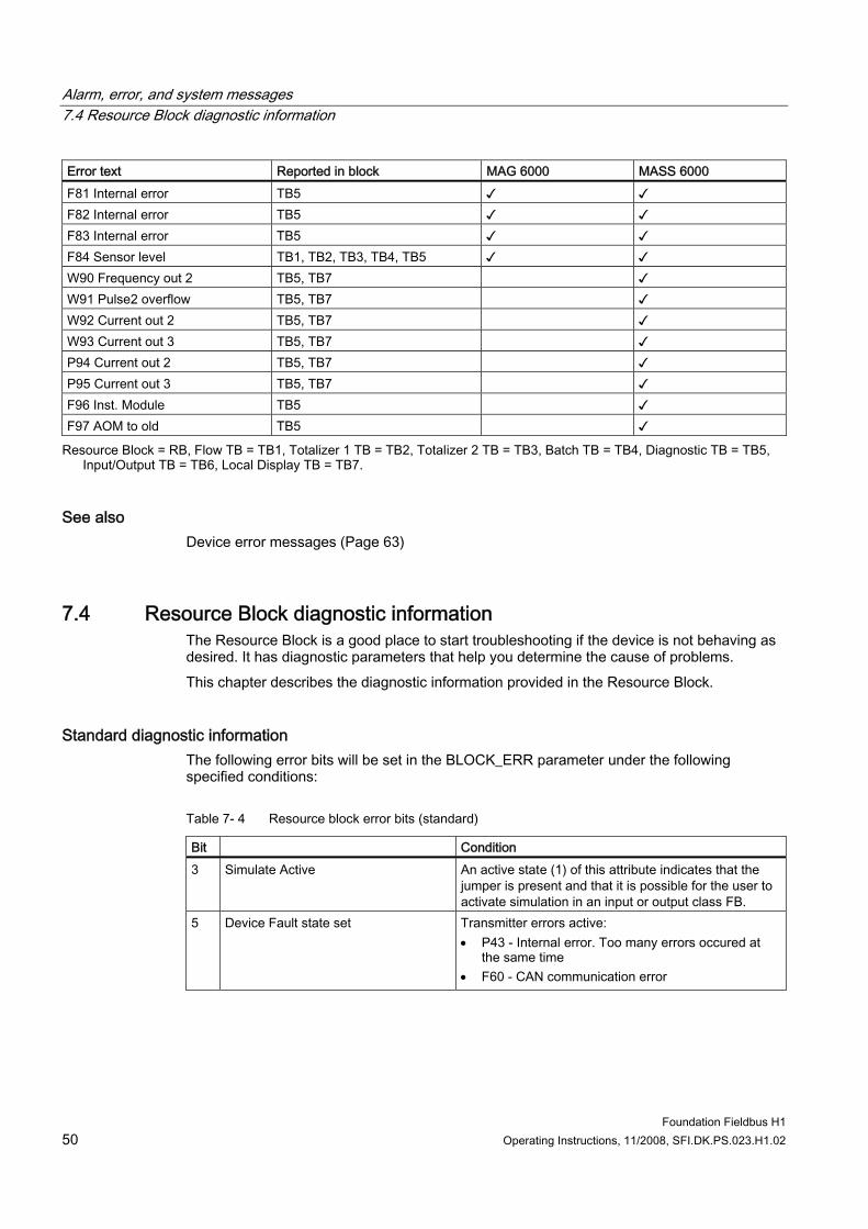
Alarm, error, and system messages 7.4 Resource Block diagnostic information
Foundation Fieldbus H1 50 Operating Instructions, 11/2008, SFI.DK.PS.023.H1.02
Error text Reported in block MAG 6000 MASS 6000 F81 Internal error TB5 ✓ ✓ F82 Internal error TB5 ✓ ✓ F83 Internal error TB5 ✓ ✓ F84 Sensor level TB1, TB2, TB3, TB4, TB5 ✓ ✓ W90 Frequency out 2 TB5, TB7 ✓ W91 Pulse2 overflow TB5, TB7 ✓ W92 Current out 2 TB5, TB7 ✓ W93 Current out 3 TB5, TB7 ✓ P94 Current out 2 TB5, TB7 ✓ P95 Current out 3 TB5, TB7 ✓ F96 Inst. Module TB5 ✓ F97 AOM to old TB5 ✓
Resource Block = RB, Flow TB = TB1, Totalizer 1 TB = TB2, Totalizer 2 TB = TB3, Batch TB = TB4, Diagnostic TB = TB5, Input/Output TB = TB6, Local Display TB = TB7.
See also Device error messages (Page 63)
7.4 Resource Block diagnostic information The Resource Block is a good place to start troubleshooting if the device is not behaving as desired. It has diagnostic parameters that help you determine the cause of problems. This chapter describes the diagnostic information provided in the Resource Block.
Standard diagnostic information The following error bits will be set in the BLOCK_ERR parameter under the following specified conditions:
Table 7- 4 Resource block error bits (standard)
Bit Condition 3 Simulate Active An active state (1) of this attribute indicates that the
jumper is present and that it is possible for the user to activate simulation in an input or output class FB.
5 Device Fault state set Transmitter errors active: • P43 - Internal error. Too many errors occured at
the same time • F60 - CAN communication error
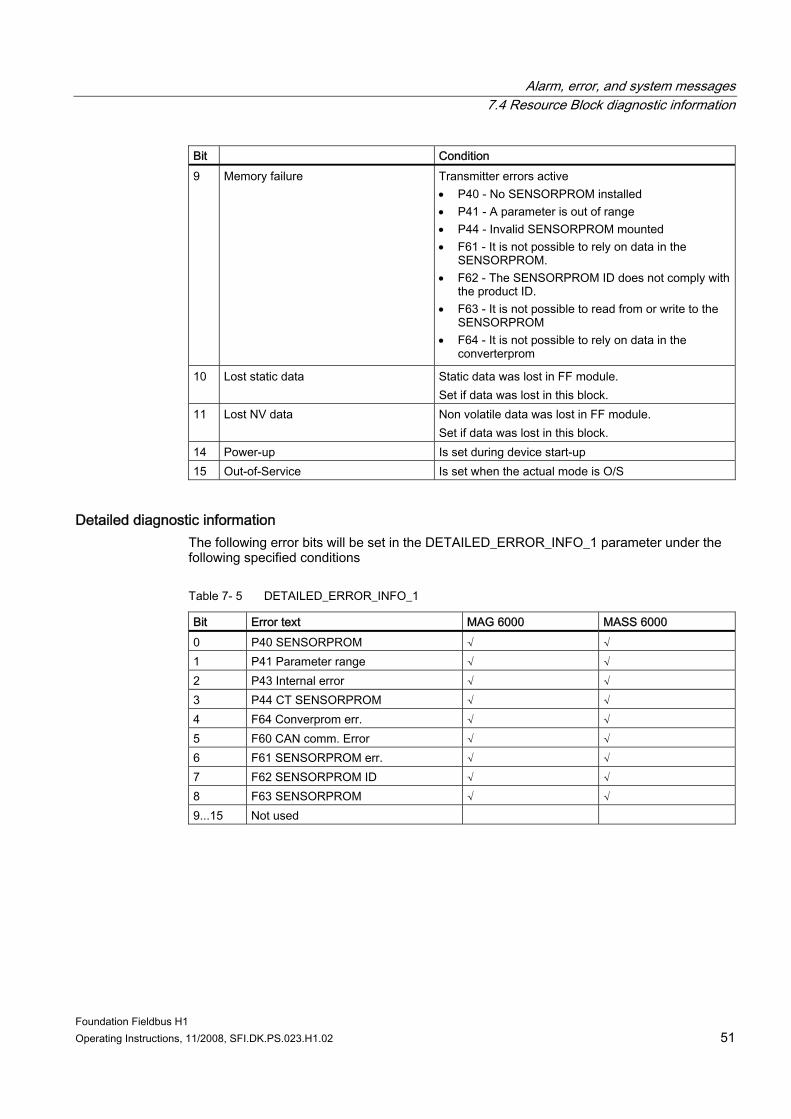
Alarm, error, and system messages 7.4 Resource Block diagnostic information
Foundation Fieldbus H1 Operating Instructions, 11/2008, SFI.DK.PS.023.H1.02 51
Bit Condition 9 Memory failure Transmitter errors active
• P40 - No SENSORPROM installed • P41 - A parameter is out of range • P44 - Invalid SENSORPROM mounted • F61 - It is not possible to rely on data in the
SENSORPROM. • F62 - The SENSORPROM ID does not comply with
the product ID. • F63 - It is not possible to read from or write to the
SENSORPROM • F64 - It is not possible to rely on data in the
converterprom
10 Lost static data Static data was lost in FF module. Set if data was lost in this block.
11 Lost NV data Non volatile data was lost in FF module. Set if data was lost in this block.
14 Power-up Is set during device start-up 15 Out-of-Service Is set when the actual mode is O/S
Detailed diagnostic information The following error bits will be set in the DETAILED_ERROR_INFO_1 parameter under the following specified conditions
Table 7- 5 DETAILED_ERROR_INFO_1
Bit Error text MAG 6000 MASS 6000 0 P40 SENSORPROM √ √ 1 P41 Parameter range √ √ 2 P43 Internal error √ √ 3 P44 CT SENSORPROM √ √ 4 F64 Converprom err. √ √ 5 F60 CAN comm. Error √ √ 6 F61 SENSORPROM err. √ √ 7 F62 SENSORPROM ID √ √ 8 F63 SENSORPROM √ √ 9...15 Not used
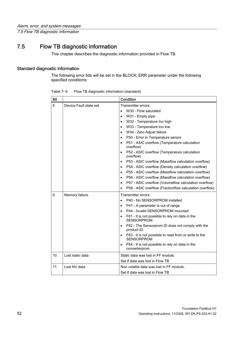
Alarm, error, and system messages 7.5 Flow TB diagnostic information
Foundation Fieldbus H1 52 Operating Instructions, 11/2008, SFI.DK.PS.023.H1.02
7.5 Flow TB diagnostic information This chapter describes the diagnostic information provided in Flow TB.
Standard diagnostic information The following error bits will be set in the BLOCK_ERR parameter under the following specified conditions:
Table 7- 6 Flow TB diagnostic information (standard)
Bit Condition 5 Device Fault state set Transmitter errors:
• W30 - Flow saturated • W31 - Empty pipe • W32 - Temperature too high • W33 - Temperature too low • W34 - Zero Adjust failure • P50 - Error in Temperature sensor • P51 - ASIC overflow (Temperature calculation
overflow) • P52 - ASIC overflow (Temperature calculation
overflow) • P53 - ASIC overflow (Massflow calculation overflow) • P54 - ASIC overflow (Density calculation overflow) • P55 - ASIC overflow (Massflow calculation overflow) • P56 - ASIC overflow (Massflow calculation overflow) • P57 - ASIC overflow (Volumeflow calculation overflow) • P58 - ASIC overflow (Fractionflow calculation overflow)
9 Memory failure Transmitter errors: • P40 - No SENSORPROM installed • P41 - A parameter is out of range • P44 - Invalid SENSORPROM mounted • F61 - It is not possible to rely on data in the
SENSORPROM. • F62 - The Sensorprom ID does not comply with the
product ID. • F63 - It is not possible to read from or write to the
SENSORPROM • F64 - It is not possible to rely on data in the
converterprom
10 Lost static data Static data was lost in FF module. Set if data was lost in Flow TB
11 Lost NV data Non volatile data was lost in FF module. Set if data was lost in Flow TB
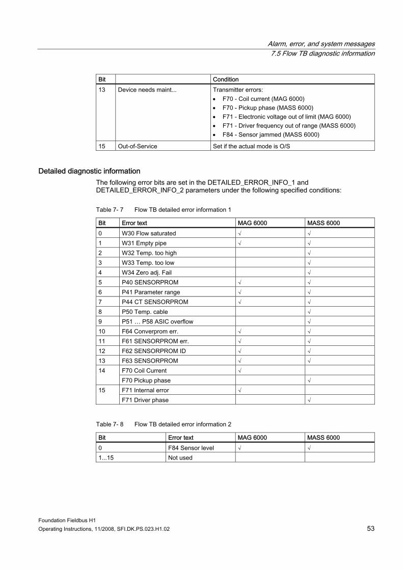
Alarm, error, and system messages 7.5 Flow TB diagnostic information
Foundation Fieldbus H1 Operating Instructions, 11/2008, SFI.DK.PS.023.H1.02 53
Bit Condition 13 Device needs maint... Transmitter errors:
• F70 - Coil current (MAG 6000) • F70 - Pickup phase (MASS 6000) • F71 - Electronic voltage out of limit (MAG 6000) • F71 - Driver frequency out of range (MASS 6000) • F84 - Sensor jammed (MASS 6000)
15 Out-of-Service Set if the actual mode is O/S
Detailed diagnostic information The following error bits are set in the DETAILED_ERROR_INFO_1 and DETAILED_ERROR_INFO_2 parameters under the following specified conditions:
Table 7- 7 Flow TB detailed error information 1
Bit Error text MAG 6000 MASS 6000 0 W30 Flow saturated √ √ 1 W31 Empty pipe √ √ 2 W32 Temp. too high √ 3 W33 Temp. too low √ 4 W34 Zero adj. Fail √ 5 P40 SENSORPROM √ √ 6 P41 Parameter range √ √ 7 P44 CT SENSORPROM √ √ 8 P50 Temp. cable √ 9 P51 … P58 ASIC overflow √ 10 F64 Converprom err. √ √ 11 F61 SENSORPROM err. √ √ 12 F62 SENSORPROM ID √ √ 13 F63 SENSORPROM √ √
F70 Coil Current √ 14 F70 Pickup phase √ F71 Internal error √ 15 F71 Driver phase √
Table 7- 8 Flow TB detailed error information 2
Bit Error text MAG 6000 MASS 6000 0 F84 Sensor level √ √ 1...15 Not used
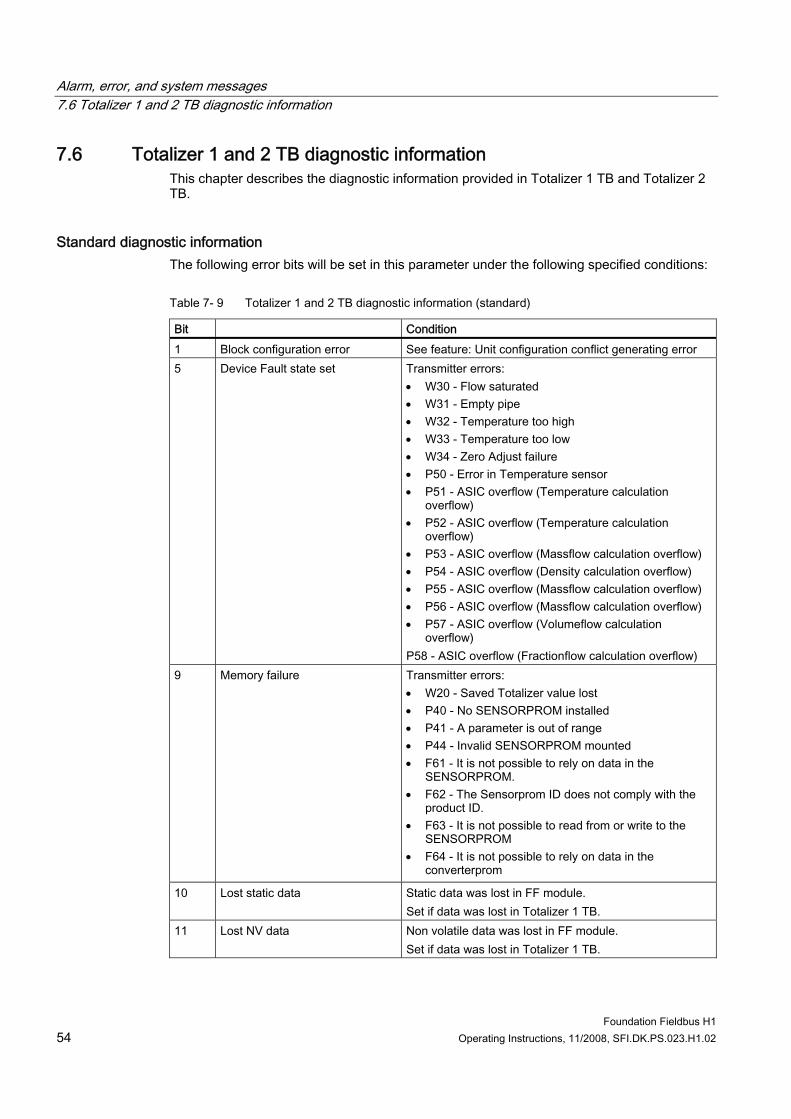
Alarm, error, and system messages 7.6 Totalizer 1 and 2 TB diagnostic information
Foundation Fieldbus H1 54 Operating Instructions, 11/2008, SFI.DK.PS.023.H1.02
7.6 Totalizer 1 and 2 TB diagnostic information This chapter describes the diagnostic information provided in Totalizer 1 TB and Totalizer 2 TB.
Standard diagnostic information The following error bits will be set in this parameter under the following specified conditions:
Table 7- 9 Totalizer 1 and 2 TB diagnostic information (standard)
Bit Condition 1 Block configuration error See feature: Unit configuration conflict generating error 5 Device Fault state set Transmitter errors:
• W30 - Flow saturated • W31 - Empty pipe • W32 - Temperature too high • W33 - Temperature too low • W34 - Zero Adjust failure • P50 - Error in Temperature sensor • P51 - ASIC overflow (Temperature calculation
overflow) • P52 - ASIC overflow (Temperature calculation
overflow) • P53 - ASIC overflow (Massflow calculation overflow) • P54 - ASIC overflow (Density calculation overflow) • P55 - ASIC overflow (Massflow calculation overflow) • P56 - ASIC overflow (Massflow calculation overflow) • P57 - ASIC overflow (Volumeflow calculation
overflow) P58 - ASIC overflow (Fractionflow calculation overflow)
9 Memory failure Transmitter errors: • W20 - Saved Totalizer value lost • P40 - No SENSORPROM installed • P41 - A parameter is out of range • P44 - Invalid SENSORPROM mounted • F61 - It is not possible to rely on data in the
SENSORPROM. • F62 - The Sensorprom ID does not comply with the
product ID. • F63 - It is not possible to read from or write to the
SENSORPROM • F64 - It is not possible to rely on data in the
converterprom
10 Lost static data Static data was lost in FF module. Set if data was lost in Totalizer 1 TB.
11 Lost NV data Non volatile data was lost in FF module. Set if data was lost in Totalizer 1 TB.
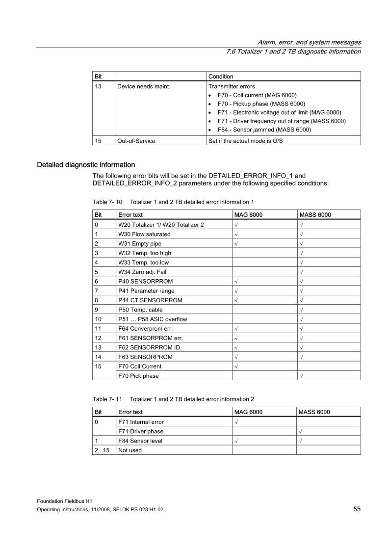
Alarm, error, and system messages 7.6 Totalizer 1 and 2 TB diagnostic information
Foundation Fieldbus H1 Operating Instructions, 11/2008, SFI.DK.PS.023.H1.02 55
Bit Condition 13 Device needs maint. Transmitter errors
• F70 - Coil current (MAG 6000) • F70 - Pickup phase (MASS 6000) • F71 - Electronic voltage out of limit (MAG 6000) • F71 - Driver frequency out of range (MASS 6000) • F84 - Sensor jammed (MASS 6000)
15 Out-of-Service Set if the actual mode is O/S
Detailed diagnostic information The following error bits will be set in the DETAILED_ERROR_INFO_1 and DETAILED_ERROR_INFO_2 parameters under the following specified conditions:
Table 7- 10 Totalizer 1 and 2 TB detailed error information 1
Bit Error text MAG 6000 MASS 6000 0 W20 Totalizer 1/ W20 Totalizer 2 √ √ 1 W30 Flow saturated √ √ 2 W31 Empty pipe √ √ 3 W32 Temp. too high √ 4 W33 Temp. too low √ 5 W34 Zero adj. Fail √ 6 P40 SENSORPROM √ √ 7 P41 Parameter range √ √ 8 P44 CT SENSORPROM √ √ 9 P50 Temp. cable √ 10 P51 … P58 ASIC overflow √ 11 F64 Converprom err. √ √ 12 F61 SENSORPROM err. √ √ 13 F62 SENSORPROM ID √ √ 14 F63 SENSORPROM √ √
F70 Coil Current √ 15 F70 Pick phase √
Table 7- 11 Totalizer 1 and 2 TB detailed error information 2
Bit Error text MAG 6000 MASS 6000 F71 Internal error √ 0 F71 Driver phase √
1 F84 Sensor level √ √ 2...15 Not used
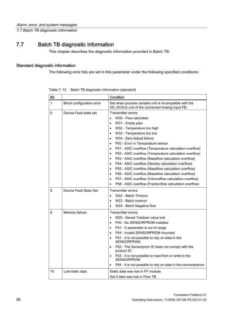
Alarm, error, and system messages 7.7 Batch TB diagnostic information
Foundation Fieldbus H1 56 Operating Instructions, 11/2008, SFI.DK.PS.023.H1.02
7.7 Batch TB diagnostic information This chapter describes the diagnostic information provided in Batch TB.
Standard diagnostic information The following error bits are set in this parameter under the following specified conditions:
Table 7- 12 Batch TB diagnostic information (standard)
Bit Condition 1 Block configuration error Set when process variable unit is incompatible with the
XD_SCALE unit of the connected Analog Input FB. 5 Device Fault state set Transmitter errors:
• W30 - Flow saturated • W31 - Empty pipe • W32 - Temperature too high • W33 - Temperature too low • W34 - Zero Adjust failure • P50 - Error in Temperature sensor • P51 - ASIC overflow (Temperature calculation overflow) • P52 - ASIC overflow (Temperature calculation overflow) • P53 - ASIC overflow (Massflow calculation overflow) • P54 - ASIC overflow (Density calculation overflow) • P55 - ASIC overflow (Massflow calculation overflow) • P56 - ASIC overflow (Massflow calculation overflow) • P57 - ASIC overflow (Volumeflow calculation overflow) • P58 - ASIC overflow (Fractionflow calculation overflow)
8 Device Fault State Set Transmitter errors: • W22 - Batch Timeout • W23 - Batch overrun • W24 - Batch Negative flow
9 Memory failure Transmitter errors: • W20 - Saved Totalizer value lost • P40 - No SENSORPROM installed • P41 - A parameter is out of range • P44 - Invalid SENSORPROM mounted • F61 - It is not possible to rely on data in the
SENSORPROM. • F62 - The Sensorprom ID does not comply with the
product ID. • F63 - It is not possible to read from or write to the
SENSORPROM • F64 - It is not possible to rely on data in the converterprom
10 Lost static data Static data was lost in FF module. Set if data was lost in Flow TB.
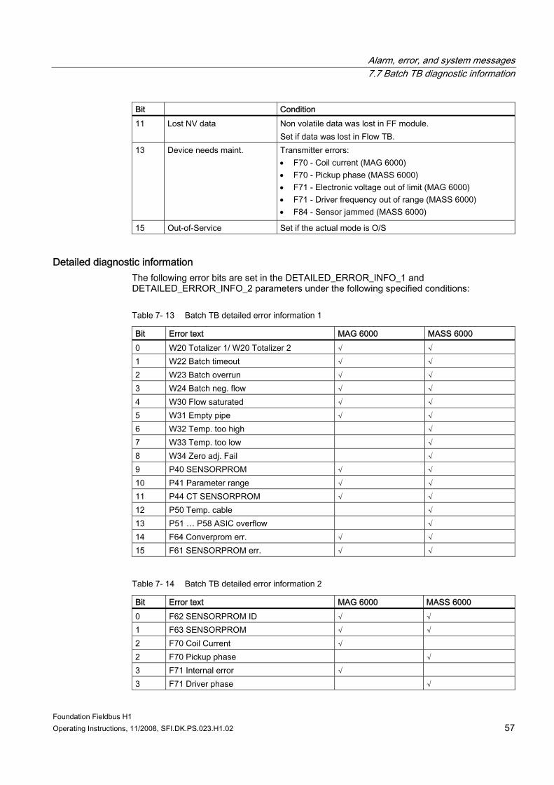
Alarm, error, and system messages 7.7 Batch TB diagnostic information
Foundation Fieldbus H1 Operating Instructions, 11/2008, SFI.DK.PS.023.H1.02 57
Bit Condition 11 Lost NV data Non volatile data was lost in FF module.
Set if data was lost in Flow TB. 13 Device needs maint. Transmitter errors:
• F70 - Coil current (MAG 6000) • F70 - Pickup phase (MASS 6000) • F71 - Electronic voltage out of limit (MAG 6000) • F71 - Driver frequency out of range (MASS 6000) • F84 - Sensor jammed (MASS 6000)
15 Out-of-Service Set if the actual mode is O/S
Detailed diagnostic information The following error bits are set in the DETAILED_ERROR_INFO_1 and DETAILED_ERROR_INFO_2 parameters under the following specified conditions:
Table 7- 13 Batch TB detailed error information 1
Bit Error text MAG 6000 MASS 6000 0 W20 Totalizer 1/ W20 Totalizer 2 √ √ 1 W22 Batch timeout √ √ 2 W23 Batch overrun √ √ 3 W24 Batch neg. flow √ √ 4 W30 Flow saturated √ √ 5 W31 Empty pipe √ √ 6 W32 Temp. too high √ 7 W33 Temp. too low √ 8 W34 Zero adj. Fail √ 9 P40 SENSORPROM √ √ 10 P41 Parameter range √ √ 11 P44 CT SENSORPROM √ √ 12 P50 Temp. cable √ 13 P51 … P58 ASIC overflow √ 14 F64 Converprom err. √ √ 15 F61 SENSORPROM err. √ √
Table 7- 14 Batch TB detailed error information 2
Bit Error text MAG 6000 MASS 6000 0 F62 SENSORPROM ID √ √ 1 F63 SENSORPROM √ √ 2 F70 Coil Current √ 2 F70 Pickup phase √ 3 F71 Internal error √ 3 F71 Driver phase √
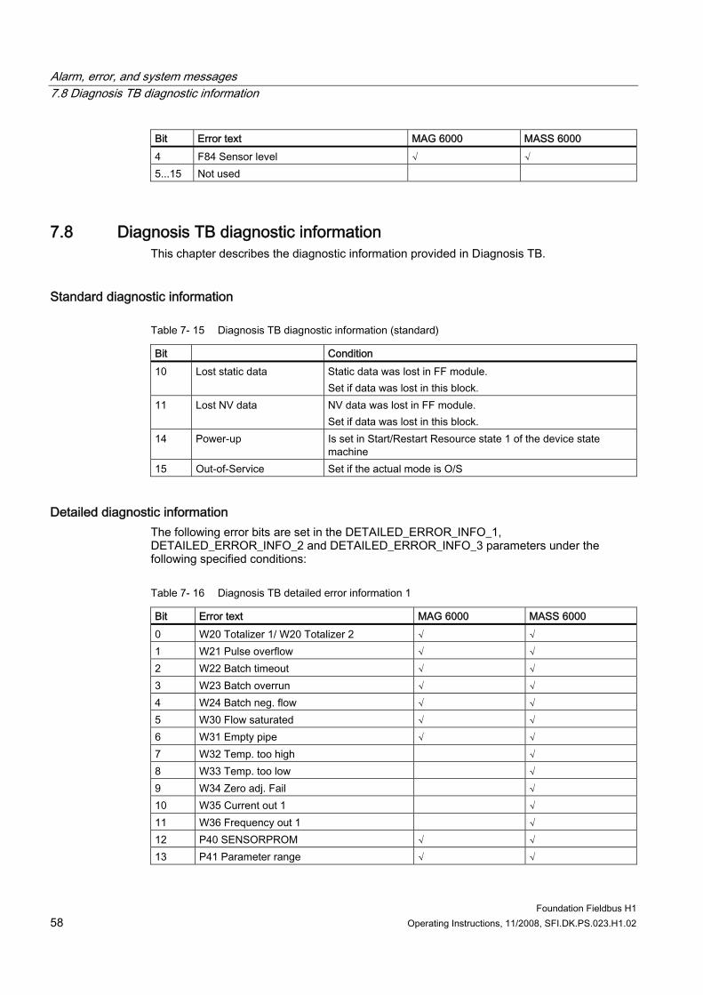
Alarm, error, and system messages 7.8 Diagnosis TB diagnostic information
Foundation Fieldbus H1 58 Operating Instructions, 11/2008, SFI.DK.PS.023.H1.02
Bit Error text MAG 6000 MASS 6000 4 F84 Sensor level √ √ 5...15 Not used
7.8 Diagnosis TB diagnostic information This chapter describes the diagnostic information provided in Diagnosis TB.
Standard diagnostic information
Table 7- 15 Diagnosis TB diagnostic information (standard)
Bit Condition 10 Lost static data Static data was lost in FF module.
Set if data was lost in this block. 11 Lost NV data NV data was lost in FF module.
Set if data was lost in this block. 14 Power-up Is set in Start/Restart Resource state 1 of the device state
machine 15 Out-of-Service Set if the actual mode is O/S
Detailed diagnostic information The following error bits are set in the DETAILED_ERROR_INFO_1, DETAILED_ERROR_INFO_2 and DETAILED_ERROR_INFO_3 parameters under the following specified conditions:
Table 7- 16 Diagnosis TB detailed error information 1
Bit Error text MAG 6000 MASS 6000 0 W20 Totalizer 1/ W20 Totalizer 2 √ √ 1 W21 Pulse overflow √ √ 2 W22 Batch timeout √ √ 3 W23 Batch overrun √ √ 4 W24 Batch neg. flow √ √ 5 W30 Flow saturated √ √ 6 W31 Empty pipe √ √ 7 W32 Temp. too high √ 8 W33 Temp. too low √ 9 W34 Zero adj. Fail √ 10 W35 Current out 1 √ 11 W36 Frequency out 1 √ 12 P40 SENSORPROM √ √ 13 P41 Parameter range √ √
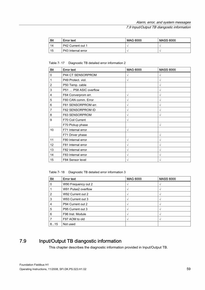
Alarm, error, and system messages 7.9 Input/Output TB diangostic information
Foundation Fieldbus H1 Operating Instructions, 11/2008, SFI.DK.PS.023.H1.02 59
Bit Error text MAG 6000 MASS 6000 14 P42 Current out 1 √ √ 15 P43 Internal error √ √
Table 7- 17 Diagnostic TB detailed error information 2
Bit Error text MAG 6000 MASS 6000 0 P44 CT SENSORPROM √ √ 1 P49 Protect. viol. √ √ 2 P50 Temp. cable √ 3 P51 … P58 ASIC overflow √ 4 F64 Converprom err. √ √ 5 F60 CAN comm. Error √ √ 6 F61 SENSORPROM err. √ √ 7 F62 SENSORPROM ID √ √ 8 F63 SENSORPROM √ √
F70 Coil Current √ 9 F70 Pickup phase √ F71 Internal error √ 10 F71 Driver phase √
11 F80 Internal error √ √ 12 F81 Internal error √ √ 13 F82 Internal error √ √ 14 F83 Internal error √ √ 15 F84 Sensor level √ √
Table 7- 18 Diagnostic TB detailed error information 3
Bit Error text MAG 6000 MASS 6000 0 W90 Frequency out 2 √ √ 1 W91 Pulse2 overflow √ √ 2 W92 Current out 2 √ √ 3 W93 Current out 3 √ √ 4 P94 Current out 2 √ √ 5 P95 Current out 3 √ √ 6 F96 Inst. Module √ √ 7 F97 AOM to old √ √ 8...15 Not used
7.9 Input/Output TB diangostic information This chapter describes the diagnostic information provided in Input/Output TB.
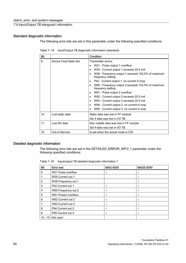
Alarm, error, and system messages 7.9 Input/Output TB diangostic information
Foundation Fieldbus H1 60 Operating Instructions, 11/2008, SFI.DK.PS.023.H1.02
Standard diagnostic information The following error bits are set in this parameter under the following specified conditions:
Table 7- 19 Input/Output TB diagnostic information (standard)
Bit Condition 8 Device Fault State Set Transmitter errors:
• W21 - Pulse output 1 overflow • W35 - Current output 1 exceeds 20.5 mA • W36 - Frequency output 1 exceeds 102,5% of maximum
frequency setting • P42 - Current output 1, no current in loop • W90 - Frequency output 2 exceeds 102,5% of maximum
frequency setting • W91 - Pulse output 2 overflow • W92 - Current output 2 exceeds 20.5 mA • W93 - Current output 3 exceeds 20.5 mA • W94 - Current output 2, no current in loop • W95 - Current output 3, no current in loop
10 Lost static data Static data was lost in FF module. Set if data was lost in I/O TB.
11 Lost NV data Non volatile data was lost in FF module. Set if data was lost in I/O TB.
15 Out-of-Service Is set when the actual mode is O/S
Detailed diagnostic information The following error bits are set in the DETAILED_ERROR_INFO_1 parameter under the following specified conditions:
Table 7- 20 Input/output TB detailed diagnostic information 1
Bit Error text MAG 6000 MASS 6000 0 W21 Pulse overflow √ √ 1 W35 Current out 1 √ 2 W36 Frequency out 1 √ 3 P42 Current out 1 √ √ 4 W90 Frequency out 2 √ √ 5 W91 Pulse2 overflow √ √ 6 W92 Current out 2 √ √ 7 W93 Current out 3 √ √ 8 P94 Current out 2 √ √ 9 P95 Current out 3 √ √ 10...15 Not used
Alarm, error, and system messages 7.10 Error examples
Foundation Fieldbus H1 Operating Instructions, 11/2008, SFI.DK.PS.023.H1.02 61
7.10 Error examples
Example 1 The flowmeter shows error "W30 Flow saturate" ● Bit 5 "Device Fault state set" is set in Flow TB, Totalizer 1, Totalizer 2, Batch and
Diagnosis TBs. ● Bit indicating "W30 Flow saturated" is set in "DETAILED_ERROR_INFO_X" in Flow TB,
Totalizer 1, Totalizer 2, Batch and Diagnosis TBs. ● Status of the channel is UNCERTAIN, Substatus EU range violation. ● Status of Analog Input FB PV and OUT is UNCERTAIN, Substatus EU range violation.
Example 2 The flowmeter shows error "F84 Sensor level" ● Bit 7 "Sensor Failure detected …" is set in Flow TB, Totalizer 1, Totalizer 2, Batch and
Diagnosis TBs. ● Bit indicating "F84 Sensor level" is set in "DETAILED_ERROR_INFO_X" in Flow TB,
Totalizer 1, Totalizer 2, Batch and Diagnosis TBs. ● Status of the channel is BAD, Substatus EU Sensor Failure. ● Status of AI Block PV and OUT is BAD, Substatus Sensor Failure. ● AI-Block BLOCK_ERR shows INPUT_FAILURE (if Propagate_Fault_Forward is not set in
STATUS_OPTS).
Example 3 Resource-Block is switched to Out of Service: ● Analog Input FB also goes to Out of Service. ● Analog Input FB BLOCK_ERR shows Out of Service. ● Analog Input FB OUT. Status is BAD, Substatus Out_Of_Service.

Alarm, error, and system messages 7.10 Error examples
Foundation Fieldbus H1 62 Operating Instructions, 11/2008, SFI.DK.PS.023.H1.02
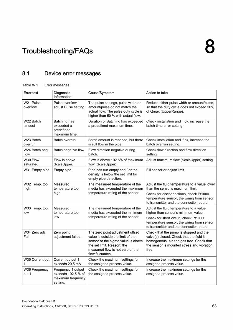
Foundation Fieldbus H1 Operating Instructions, 11/2008, SFI.DK.PS.023.H1.02 63
Troubleshooting/FAQs 88.1 Device error messages
Table 8- 1 Error messages
Error text Diagnostic Information
Cause/Symptom Action to take
W21 Pulse overflow
Pulse overflow - adjust Pulse setting.
The pulse settings, pulse width or amount/pulse do not match the actual flow. The pulse duty cycle is higher than 50 % with actual flow.
Reduce either pulse width or amount/pulse, so that the duty cycle does not exceed 50% of Qmax (UpperRange).
W22 Batch timeout
Batching has exceeded a predefined maximum time.
Duration of Batching has exceeded a predefined maximum time.
Check installation and if ok, increase the batch time error setting.
W23 Batch overrun
Batch overrun. Batch amount is reached, but there is still flow in the pipe.
Check installation and if ok, increase the batch overrun setting.
W24 Batch neg. flow
Batch negative flow .
Flow direction negative during batch.
Check flow direction and flow direction setting.
W30 Flow saturated
Flow is above ScaleUpper.
Flow is above 102.5% of maximum flow (ScaleUpper).
Adjust maximum flow (ScaleUpper) setting.
W31 Empty pipe Empty pipe. Pipe has run empty and / or the density is below the set limit for empty pipe detection.
Fill sensor or adjust limit.
W32 Temp. too high
Measured temperature too high.
The measured temperature of the media has exceeded the maximum temperature rating of the sensor.
Adjust the fluid temperature to a value lower than the sensor's maximum limit. Check for disconnections, check Pt1000 temperature sensor, the wiring from sensor to transmitter and the connection board.
W33 Temp. too low
Measured temperature too low.
The measured temperature of the media has exceeded the minimum temperature rating of the sensor.
Adjust the fluid temperature to a value higher than sensor's minimum value. Check for short circuit, check Pt1000 temperature sensor, the wiring from sensor to transmitter and the connection board.
W34 Zero adj. Fail
Zero point adjustment failed.
The zero point adjustment offset value is outside the limit of the sensor or the sigma value is above the set limit. Reason: the measured flow is not zero or the flow fluctuates.
Check that the pump is stopped and the valve(s) closed. Check that the fluid is homogenous, air and gas free. Check that the sensor is mounted stress and vibration free.
W35 Current out 1
Current output 1 exceeds 20,5 mA
Check the maximum settings for the assigned process value.
Increase the maximum settings for the assigned process value.
W36 Frequency out 1
Frequency 1 output exceeds 102,5 % of maximum frequency setting.
Check the maximum settings for the assigned process value.
Increase the maximum settings for the assigned process value.
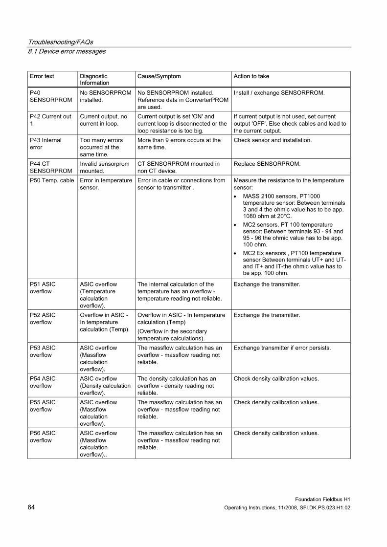
Troubleshooting/FAQs 8.1 Device error messages
Foundation Fieldbus H1 64 Operating Instructions, 11/2008, SFI.DK.PS.023.H1.02
Error text Diagnostic Information
Cause/Symptom Action to take
P40 SENSORPROM
No SENSORPROM installed.
No SENSORPROM installed. Reference data in ConverterPROM are used.
Install / exchange SENSORPROM.
P42 Current out 1
Current output, no current in loop.
Current output is set 'ON' and current loop is disconnected or the loop resistance is too big.
If current output is not used, set current output 'OFF'. Else check cables and load to the current output.
P43 Internal error
Too many errors occurred at the same time.
More than 9 errors occurs at the same time.
Check sensor and installation.
P44 CT SENSORPROM
Invalid sensorprom mounted.
CT SENSORPROM mounted in non CT device.
Replace SENSORPROM.
P50 Temp. cable Error in temperature sensor.
Error in cable or connections from sensor to transmitter .
Measure the resistance to the temperature sensor: • MASS 2100 sensors, PT1000
temperature sensor: Between terminals 3 and 4 the ohmic value has to be app. 1080 ohm at 20°C.
• MC2 sensors, PT 100 temperature sensor: Between terminals 93 - 94 and 95 - 96 the ohmic value has to be app. 100 ohm.
• MC2 Ex sensors , PT100 temperature sensor Between terminals UT+ and UT- and IT+ and IT-the ohmic value has to be app. 100 ohm.
P51 ASIC overflow
ASIC overflow (Temperature calculation overflow).
The internal calculation of the temperature has an overflow - temperature reading not reliable.
Exchange the transmitter.
P52 ASIC overflow
Overflow in ASIC - In temperature calculation (Temp).
Overflow in ASIC - In temperature calculation (Temp) (Overflow in the secondary temperature calculations).
Exchange the transmitter.
P53 ASIC overflow
ASIC overflow (Massflow calculation overflow).
The massflow calculation has an overflow - massflow reading not reliable.
Exchange transmitter if error persists.
P54 ASIC overflow
ASIC overflow (Density calculation overflow).
The density calculation has an overflow - density reading not reliable.
Check density calibration values.
P55 ASIC overflow
ASIC overflow (Massflow calculation overflow).
The massflow calculation has an overflow - massflow reading not reliable.
Check density calibration values.
P56 ASIC overflow
ASIC overflow (Massflow calculation overflow)..
The massflow calculation has an overflow - massflow reading not reliable.
Check density calibration values.
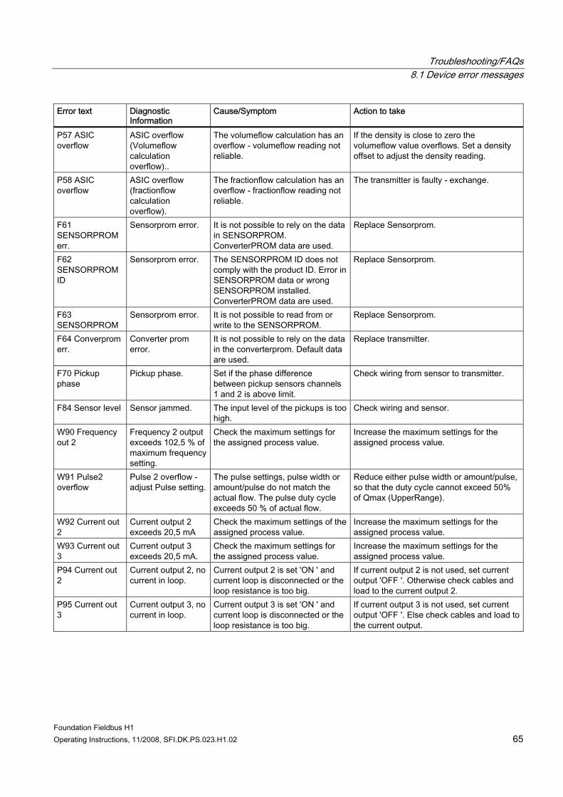
Troubleshooting/FAQs 8.1 Device error messages
Foundation Fieldbus H1 Operating Instructions, 11/2008, SFI.DK.PS.023.H1.02 65
Error text Diagnostic Information
Cause/Symptom Action to take
P57 ASIC overflow
ASIC overflow (Volumeflow calculation overflow)..
The volumeflow calculation has an overflow - volumeflow reading not reliable.
If the density is close to zero the volumeflow value overflows. Set a density offset to adjust the density reading.
P58 ASIC overflow
ASIC overflow (fractionflow calculation overflow).
The fractionflow calculation has an overflow - fractionflow reading not reliable.
The transmitter is faulty - exchange.
F61 SENSORPROM err.
Sensorprom error. It is not possible to rely on the data in SENSORPROM. ConverterPROM data are used.
Replace Sensorprom.
F62 SENSORPROM ID
Sensorprom error. The SENSORPROM ID does not comply with the product ID. Error in SENSORPROM data or wrong SENSORPROM installed. ConverterPROM data are used.
Replace Sensorprom.
F63 SENSORPROM
Sensorprom error. It is not possible to read from or write to the SENSORPROM.
Replace Sensorprom.
F64 Converprom err.
Converter prom error.
It is not possible to rely on the data in the converterprom. Default data are used.
Replace transmitter.
F70 Pickup phase
Pickup phase. Set if the phase difference between pickup sensors channels 1 and 2 is above limit.
Check wiring from sensor to transmitter.
F84 Sensor level Sensor jammed. The input level of the pickups is too high.
Check wiring and sensor.
W90 Frequency out 2
Frequency 2 output exceeds 102,5 % of maximum frequency setting.
Check the maximum settings for the assigned process value.
Increase the maximum settings for the assigned process value.
W91 Pulse2 overflow
Pulse 2 overflow - adjust Pulse setting.
The pulse settings, pulse width or amount/pulse do not match the actual flow. The pulse duty cycle exceeds 50 % of actual flow.
Reduce either pulse width or amount/pulse, so that the duty cycle cannot exceed 50% of Qmax (UpperRange).
W92 Current out 2
Current output 2 exceeds 20,5 mA
Check the maximum settings of the assigned process value.
Increase the maximum settings for the assigned process value.
W93 Current out 3
Current output 3 exceeds 20,5 mA.
Check the maximum settings for the assigned process value.
Increase the maximum settings for the assigned process value.
P94 Current out 2
Current output 2, no current in loop.
Current output 2 is set 'ON ' and current loop is disconnected or the loop resistance is too big.
If current output 2 is not used, set current output 'OFF '. Otherwise check cables and load to the current output 2.
P95 Current out 3
Current output 3, no current in loop.
Current output 3 is set 'ON ' and current loop is disconnected or the loop resistance is too big.
If current output 3 is not used, set current output 'OFF '. Else check cables and load to the current output.
Troubleshooting/FAQs 8.2 Analog Input FB cannot be set to AUTO
Foundation Fieldbus H1 66 Operating Instructions, 11/2008, SFI.DK.PS.023.H1.02
8.2 Analog Input FB cannot be set to AUTO The AUTO mode of an Analog Input FB requires the following settings: 1. Set the Resource Block to AUTO. 2. Within the Analog Input FB a valid channel has to be entered (1 to 10 for MASS 6000; 1,
8, 9, 10 for MAG 6000). 3. L_Type has to be set to direct or indirect (indirect square root is likewise possible, yet not
sensible). 4. XD_SCALE unit has to be compatible with the selected channel unit for channels 4 to 8.
I.e. the units must be within the same unit family. 5. With L_Type "Direct the XD_SCALE and OUT_SCALE structures have to be identical.
8.3 Parameter cannot be written The following error messages can appear while writing a parameter within the NI Configurator: 1. Writing is prohibited (Error code 40)
– The write protect switch is deactivated Check the switch position at the device or via the WRITE_LOCK parameter (to be found within the NI Configurator in the Resource Block window below the strap "options"). The respective parameter (with current configuration) cannot be written. See description of respective parameter.
2. Wrong Mode for Request (Error code 39) Some parameters can merely be written if the target mode is set to OOS. Other parameters can also be written in mode MAN and still others can be written in each of the target modes.
3. Exceed Limit (Error code 38) An attempt was made to write a value outside the permitted limits of a parameter. Consult the parameter description about permitted limits and values.
8.4 PID Block cannot be set to AUTO The AUTO mode of a PID FB requires the following settings: 1. Set the Resource Block to AUTO. 2. Make sure bypass is not set to default value "uninitialized". 3. Make sure Shed_Opt is not set to default value "uninitialized". 4. Make sure Gain and SP are set. 5. FBAP schedule must be downloaded
PID actual mode remains in mode IMAN ● Check the function block behind the PID and check the back calculation path and value.
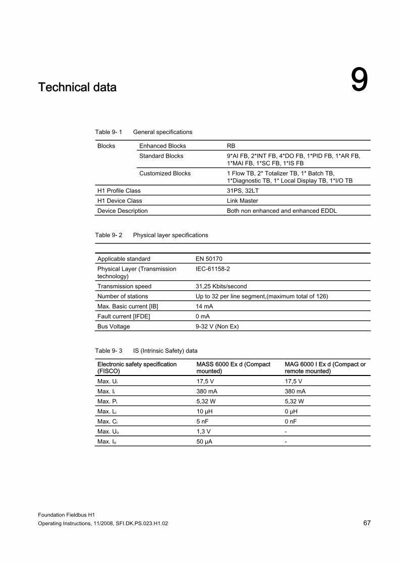
Foundation Fieldbus H1 Operating Instructions, 11/2008, SFI.DK.PS.023.H1.02 67
Technical data 9
Table 9- 1 General specifications
Enhanced Blocks RB Standard Blocks 9*AI FB, 2*INT FB, 4*DO FB, 1*PID FB, 1*AR FB,
1*MAI FB, 1*SC FB, 1*IS FB
Blocks
Customized Blocks 1 Flow TB, 2* Totalizer TB, 1* Batch TB, 1*Diagnostic TB, 1* Local Display TB, 1*I/O TB
H1 Profile Class 31PS, 32LT H1 Device Class Link Master Device Description Both non enhanced and enhanced EDDL
Table 9- 2 Physical layer specifications
Applicable standard EN 50170 Physical Layer (Transmission technology)
IEC-61158-2
Transmission speed 31,25 Kbits/second Number of stations Up to 32 per line segment,(maximum total of 126) Max. Basic current [IB] 14 mA Fault current [IFDE] 0 mA Bus Voltage 9-32 V (Non Ex)
Table 9- 3 IS (Intrinsic Safety) data
Electronic safety specification (FISCO)
MASS 6000 Ex d (Compact mounted)
MAG 6000 I Ex d (Compact or remote mounted)
Max. Ui 17,5 V 17,5 V Max. Ii 380 mA 380 mA Max. Pi 5,32 W 5,32 W Max. Li 10 μH 0 μH Max. Ci 5 nF 0 nF Max. Uo 1,3 V - Max. Io 50 μA -
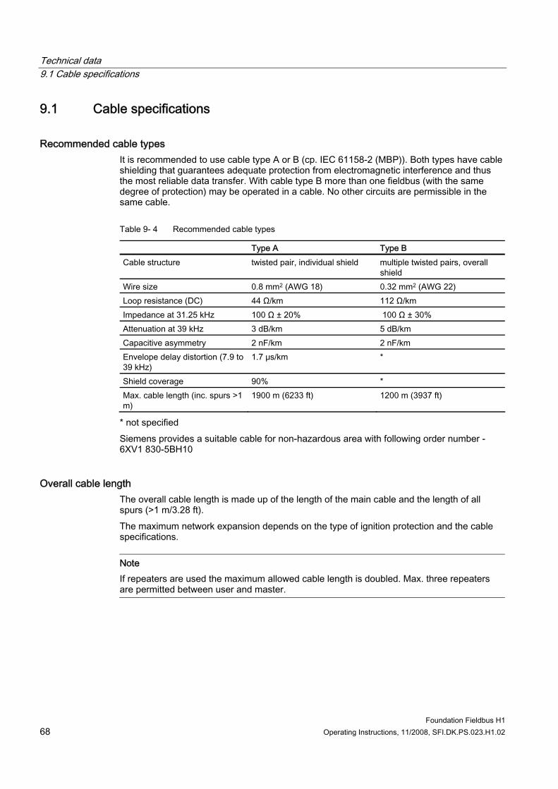
Technical data 9.1 Cable specifications
Foundation Fieldbus H1 68 Operating Instructions, 11/2008, SFI.DK.PS.023.H1.02
9.1 Cable specifications
Recommended cable types It is recommended to use cable type A or B (cp. IEC 61158-2 (MBP)). Both types have cable shielding that guarantees adequate protection from electromagnetic interference and thus the most reliable data transfer. With cable type B more than one fieldbus (with the same degree of protection) may be operated in a cable. No other circuits are permissible in the same cable.
Table 9- 4 Recommended cable types
Type A Type B Cable structure twisted pair, individual shield multiple twisted pairs, overall
shield Wire size 0.8 mm2 (AWG 18) 0.32 mm2 (AWG 22) Loop resistance (DC) 44 Ω/km 112 Ω/km Impedance at 31.25 kHz 100 Ω ± 20% 100 Ω ± 30% Attenuation at 39 kHz 3 dB/km 5 dB/km Capacitive asymmetry 2 nF/km 2 nF/km Envelope delay distortion (7.9 to 39 kHz)
1.7 μs/km *
Shield coverage 90% * Max. cable length (inc. spurs >1 m)
1900 m (6233 ft) 1200 m (3937 ft)
* not specified Siemens provides a suitable cable for non-hazardous area with following order number - 6XV1 830-5BH10
Overall cable length The overall cable length is made up of the length of the main cable and the length of all spurs (>1 m/3.28 ft). The maximum network expansion depends on the type of ignition protection and the cable specifications.
Note If repeaters are used the maximum allowed cable length is doubled. Max. three repeaters are permitted between user and master.

Technical data 9.1 Cable specifications
Foundation Fieldbus H1 Operating Instructions, 11/2008, SFI.DK.PS.023.H1.02 69
Spurs The line between distribution box and field unit is described as a spur. By non Ex applications the max. length of a spur depends on the number of spurs (>1 m/3.28 ft):
Number of spurs 1 to 12 13 to 14 15 to 18 19 to 24 25 to 32 Max. length per spur 120 m (393 ft) 90 m (295 ft) 60 m (196 ft) 30 m (98 ft) -

Technical data 9.1 Cable specifications
Foundation Fieldbus H1 70 Operating Instructions, 11/2008, SFI.DK.PS.023.H1.02
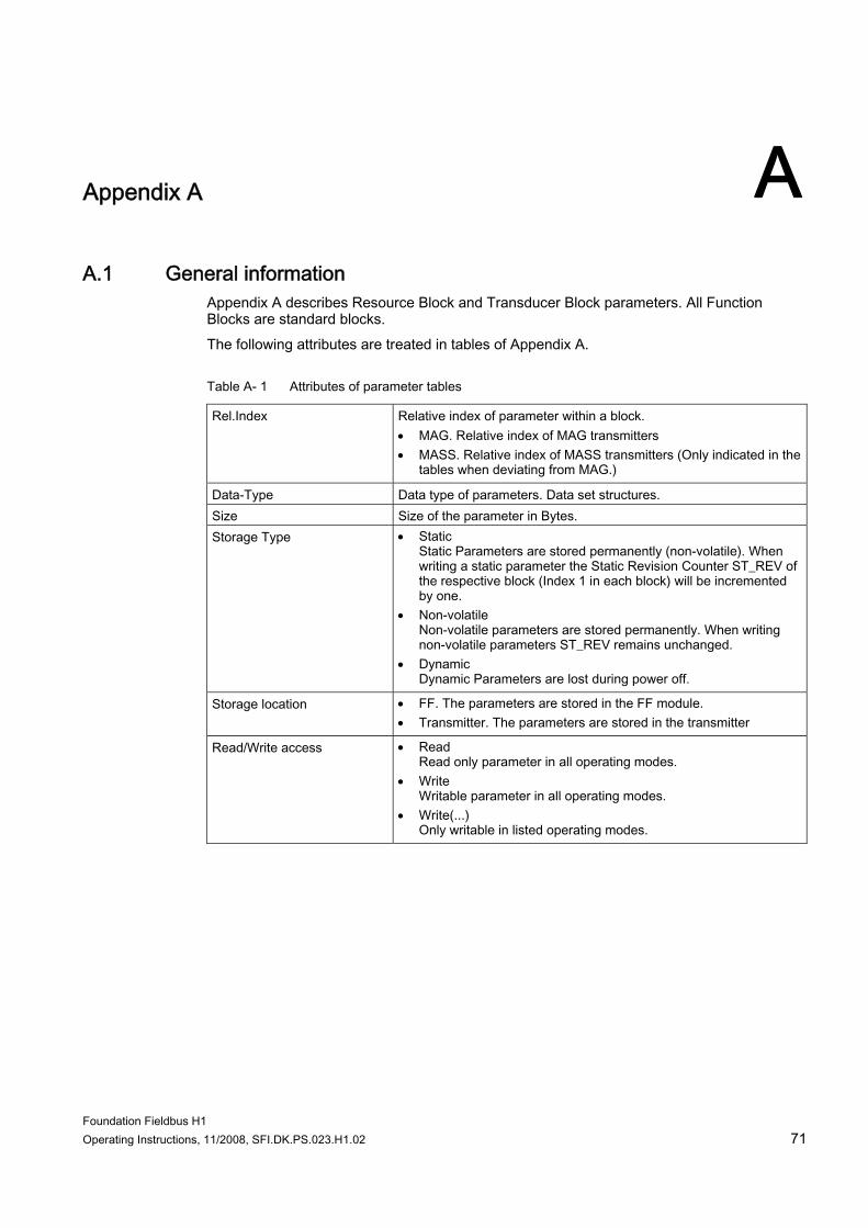
Foundation Fieldbus H1 Operating Instructions, 11/2008, SFI.DK.PS.023.H1.02 71
Appendix A AA.1 General information
Appendix A describes Resource Block and Transducer Block parameters. All Function Blocks are standard blocks. The following attributes are treated in tables of Appendix A.
Table A- 1 Attributes of parameter tables
Rel.Index Relative index of parameter within a block. • MAG. Relative index of MAG transmitters • MASS. Relative index of MASS transmitters (Only indicated in the
tables when deviating from MAG.)
Data-Type Data type of parameters. Data set structures. Size Size of the parameter in Bytes. Storage Type • Static
Static Parameters are stored permanently (non-volatile). When writing a static parameter the Static Revision Counter ST_REV of the respective block (Index 1 in each block) will be incremented by one.
• Non-volatile Non-volatile parameters are stored permanently. When writing non-volatile parameters ST_REV remains unchanged.
• Dynamic Dynamic Parameters are lost during power off.
Storage location • FF. The parameters are stored in the FF module. • Transmitter. The parameters are stored in the transmitter
Read/Write access • Read Read only parameter in all operating modes.
• Write Writable parameter in all operating modes.
• Write(...) Only writable in listed operating modes.
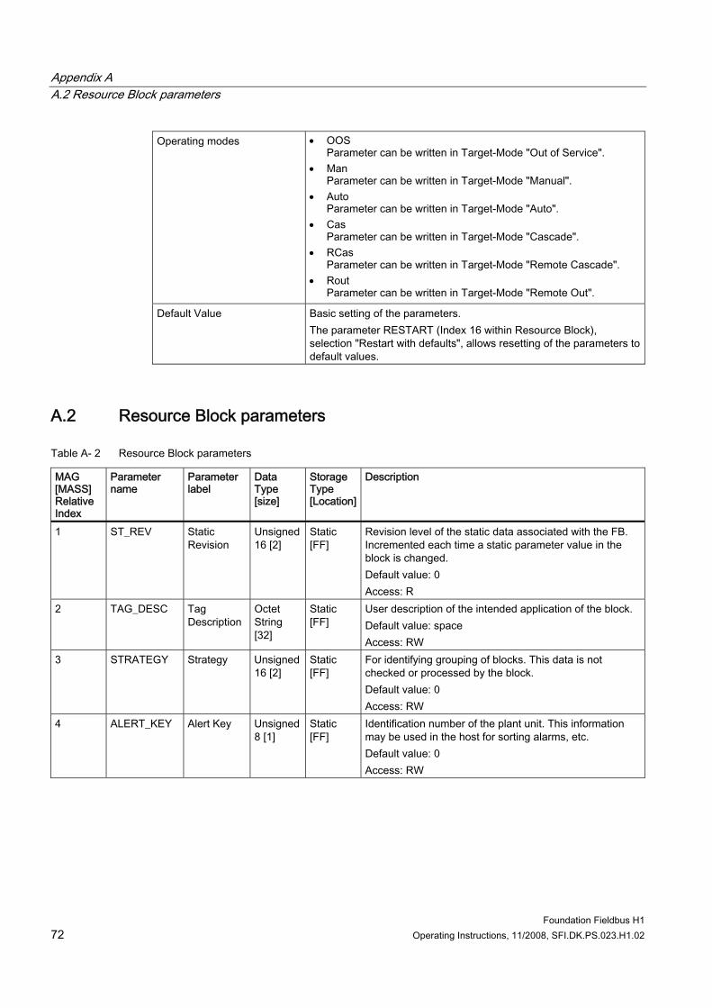
Appendix A A.2 Resource Block parameters
Foundation Fieldbus H1 72 Operating Instructions, 11/2008, SFI.DK.PS.023.H1.02
Operating modes • OOS Parameter can be written in Target-Mode "Out of Service".
• Man Parameter can be written in Target-Mode "Manual".
• Auto Parameter can be written in Target-Mode "Auto".
• Cas Parameter can be written in Target-Mode "Cascade".
• RCas Parameter can be written in Target-Mode "Remote Cascade".
• Rout Parameter can be written in Target-Mode "Remote Out".
Default Value Basic setting of the parameters. The parameter RESTART (Index 16 within Resource Block), selection "Restart with defaults", allows resetting of the parameters to default values.
A.2 Resource Block parameters
Table A- 2 Resource Block parameters
MAG [MASS] Relative Index
Parameter name
Parameter label
Data Type [size]
Storage Type [Location]
Description
1 ST_REV Static Revision
Unsigned 16 [2]
Static [FF]
Revision level of the static data associated with the FB. Incremented each time a static parameter value in the block is changed. Default value: 0 Access: R
2 TAG_DESC Tag Description
Octet String [32]
Static [FF]
User description of the intended application of the block. Default value: space Access: RW
3 STRATEGY Strategy Unsigned 16 [2]
Static [FF]
For identifying grouping of blocks. This data is not checked or processed by the block. Default value: 0 Access: RW
4 ALERT_KEY Alert Key Unsigned 8 [1]
Static [FF]
Identification number of the plant unit. This information may be used in the host for sorting alarms, etc. Default value: 0 Access: RW
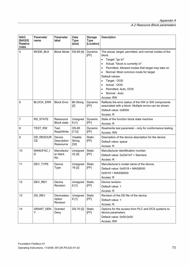
Appendix A A.2 Resource Block parameters
Foundation Fieldbus H1 Operating Instructions, 11/2008, SFI.DK.PS.023.H1.02 73
MAG [MASS] Relative Index
Parameter name
Parameter label
Data Type [size]
Storage Type [Location]
Description
5 MODE_BLK Block Mode DS-69 [4] Dynamic [FF]
The actual, target, permitted, and normal modes of the block. • Target: "go to" • Actual: "block is currently in" • Permitted: Allowed modes that target may take on • Normal: Most common mode for target Default values: • Target : OOS • Actual : OOS • Permitted: Auto, OOS • Normal : Auto Access: RW
6 BLOCK_ERR Block Error Bit String [2]
Dynamic [FF]
Reflects the error status of the HW or SW components associated with a block. Multiple errors can be shown. Default value: 0x8000 Access: R
7 RS_STATE Ressource Block state
Unsigned 8 [1]
Dynamic [FF]
State of the function block state machine Access: R
8 TEST_RW Test Read/Write
DS-85 [112]
Dynamic [FF]
Read/write test parameter - only for conformance testing. Access: RW
9 DD_RESOURCE
Device Description Ressource
Visable String [32]
Static [FF]
Description of the device description for the device. Default value: space Access: R
10 MANUFAC_ID
Manufacturer Ident. No.
Unsigned 32 [4]
Static [FF]
Manufacturer identification number. Default value: 0x534147 = Siemens Access: R
11 DEV_TYPE Device Type
Unsigned 16 [2]
Static [FF]
Manufacturer’s model name of the device. Default value: 0x0018 = MAG6000 0x0019 = MASS6000 Access: R
12 DEV_REV Device Revision
Unsigned 8 [1]
Static [FF]
Device revision. Default value: 1 Access: R
13 DD_REV Devicedescription Revision
Unsigned 8 [1]
Static [FF]
Revision of the DD file of the device. Default value: 1 Access: R
14 GRANT_DENY
Granted Deny
DS-70 [2] Static [FF]
Options for the access from PLC and DCS systems to device parameters. Default value: 0x00;0x00 Access: RW
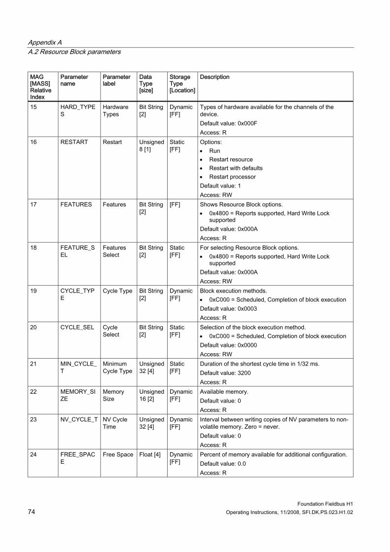
Appendix A A.2 Resource Block parameters
Foundation Fieldbus H1 74 Operating Instructions, 11/2008, SFI.DK.PS.023.H1.02
MAG [MASS] Relative Index
Parameter name
Parameter label
Data Type [size]
Storage Type [Location]
Description
15 HARD_TYPES
Hardware Types
Bit String [2]
Dynamic [FF]
Types of hardware available for the channels of the device. Default value: 0x000F Access: R
16 RESTART Restart Unsigned 8 [1]
Static [FF]
Options: • Run • Restart resource • Restart with defaults • Restart processor Default value: 1 Access: RW
17 FEATURES Features Bit String [2]
[FF] Shows Resource Block options. • 0x4800 = Reports supported, Hard Write Lock
supported Default value: 0x000A Access: R
18 FEATURE_SEL
Features Select
Bit String [2]
Static [FF]
For selecting Resource Block options. • 0x4800 = Reports supported, Hard Write Lock
supported Default value: 0x000A Access: RW
19 CYCLE_TYPE
Cycle Type Bit String [2]
Dynamic [FF]
Block execution methods. • 0xC000 = Scheduled, Completion of block execution Default value: 0x0003 Access: R
20 CYCLE_SEL Cycle Select
Bit String [2]
Static [FF]
Selection of the block execution method. • 0xC000 = Scheduled, Completion of block execution Default value: 0x0000 Access: RW
21 MIN_CYCLE_T
Minimum Cycle Type
Unsigned 32 [4]
Static [FF]
Duration of the shortest cycle time in 1/32 ms. Default value: 3200 Access: R
22 MEMORY_SIZE
Memory Size
Unsigned 16 [2]
Dynamic [FF]
Available memory. Default value: 0 Access: R
23 NV_CYCLE_T NV Cycle Time
Unsigned 32 [4]
Dynamic [FF]
Interval between writing copies of NV parameters to non-volatile memory. Zero = never. Default value: 0 Access: R
24 FREE_SPACE
Free Space Float [4] Dynamic [FF]
Percent of memory available for additional configuration. Default value: 0.0 Access: R
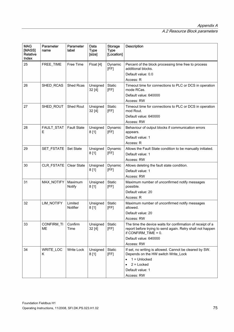
Appendix A A.2 Resource Block parameters
Foundation Fieldbus H1 Operating Instructions, 11/2008, SFI.DK.PS.023.H1.02 75
MAG [MASS] Relative Index
Parameter name
Parameter label
Data Type [size]
Storage Type [Location]
Description
25 FREE_TIME Free Time Float [4] Dynamic [FF]
Percent of the block processing time free to process additional blocks. Default value: 0.0 Access: R
26 SHED_RCAS Shed Rcas Unsigned 32 [4]
Static [FF]
Timeout time for connections to PLC or DCS in operation mode RCas. Default value: 640000 Access: RW
27 SHED_ROUT Shed Rout Unsigned 32 [4]
Static [FF]
Timeout time for connections to PLC or DCS in operation mod Rout. Default value: 640000 Access: RW
28 FAULT_STATE
Fault State Unsigned 8 [1]
Dynamic [FF]
Behaviour of output blocks if communication errors appears. Default value: 1 Access: R
29 SET_FSTATE Set State Unsigned 8 [1]
Dynamic [FF]
Allows the Fault State condition to be manually initiated. Default value: 1 Access: RW
30 CLR_FSTATE Clear State Unsigned 8 [1]
Dynamic [FF]
Allows deleting the fault state condition. Default value: 1 Access: RW
31 MAX_NOTIFY Maximum Notify
Unsigned 8 [1]
Static [FF]
Maximum number of unconfirmed notify messages possible. Default value: 20 Access: R
32 LIM_NOTIFY Limited Notifier
Unsigned 8 [1]
Static [FF]
Maximum number of unconfirmed notify messages allowed. Default value: 20 Access: RW
33 CONFIRM_TIME
Confirm Time
Unsigned 32 [4]
Static [FF]
The time the device waits for confirmation of receipt of a report before trying to send again. Retry shall not happen if CONFIRM_TIME = 0. Default value: 640000 Access: RW
34 WRITE_LOCK
Write Lock Unsigned 8 [1]
Static [FF]
If set, no writing is allowed. Cannot be cleared by SW. Depends on the HW switch Write_Lock • 1 = Unlocked • 2 = Locked Default value: 1 Access: RW
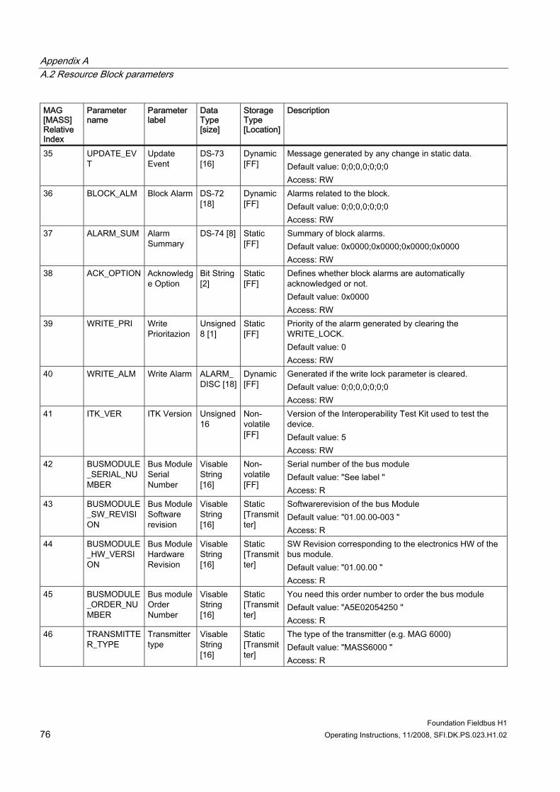
Appendix A A.2 Resource Block parameters
Foundation Fieldbus H1 76 Operating Instructions, 11/2008, SFI.DK.PS.023.H1.02
MAG [MASS] Relative Index
Parameter name
Parameter label
Data Type [size]
Storage Type [Location]
Description
35 UPDATE_EVT
Update Event
DS-73 [16]
Dynamic [FF]
Message generated by any change in static data. Default value: 0;0;0,0;0;0;0 Access: RW
36 BLOCK_ALM Block Alarm DS-72 [18]
Dynamic [FF]
Alarms related to the block. Default value: 0;0;0,0;0;0;0 Access: RW
37 ALARM_SUM Alarm Summary
DS-74 [8] Static [FF]
Summary of block alarms. Default value: 0x0000;0x0000;0x0000;0x0000 Access: RW
38 ACK_OPTION Acknowledge Option
Bit String [2]
Static [FF]
Defines whether block alarms are automatically acknowledged or not. Default value: 0x0000 Access: RW
39 WRITE_PRI Write Prioritazion
Unsigned 8 [1]
Static [FF]
Priority of the alarm generated by clearing the WRITE_LOCK. Default value: 0 Access: RW
40 WRITE_ALM Write Alarm ALARM_DISC [18]
Dynamic [FF]
Generated if the write lock parameter is cleared. Default value: 0;0;0,0;0;0;0 Access: RW
41 ITK_VER ITK Version Unsigned 16
Non-volatile [FF]
Version of the Interoperability Test Kit used to test the device. Default value: 5 Access: RW
42 BUSMODULE_SERIAL_NUMBER
Bus Module Serial Number
Visable String [16]
Non-volatile [FF]
Serial number of the bus module Default value: "See label " Access: R
43 BUSMODULE_SW_REVISION
Bus Module Software revision
Visable String [16]
Static [Transmitter]
Softwarerevision of the bus Module Default value: "01.00.00-003 " Access: R
44 BUSMODULE_HW_VERSION
Bus Module Hardware Revision
Visable String [16]
Static [Transmitter]
SW Revision corresponding to the electronics HW of the bus module. Default value: "01.00.00 " Access: R
45 BUSMODULE_ORDER_NUMBER
Bus module Order Number
Visable String [16]
Static [Transmitter]
You need this order number to order the bus module Default value: "A5E02054250 " Access: R
46 TRANSMITTER_TYPE
Transmitter type
Visable String [16]
Static [Transmitter]
The type of the transmitter (e.g. MAG 6000) Default value: "MASS6000 " Access: R
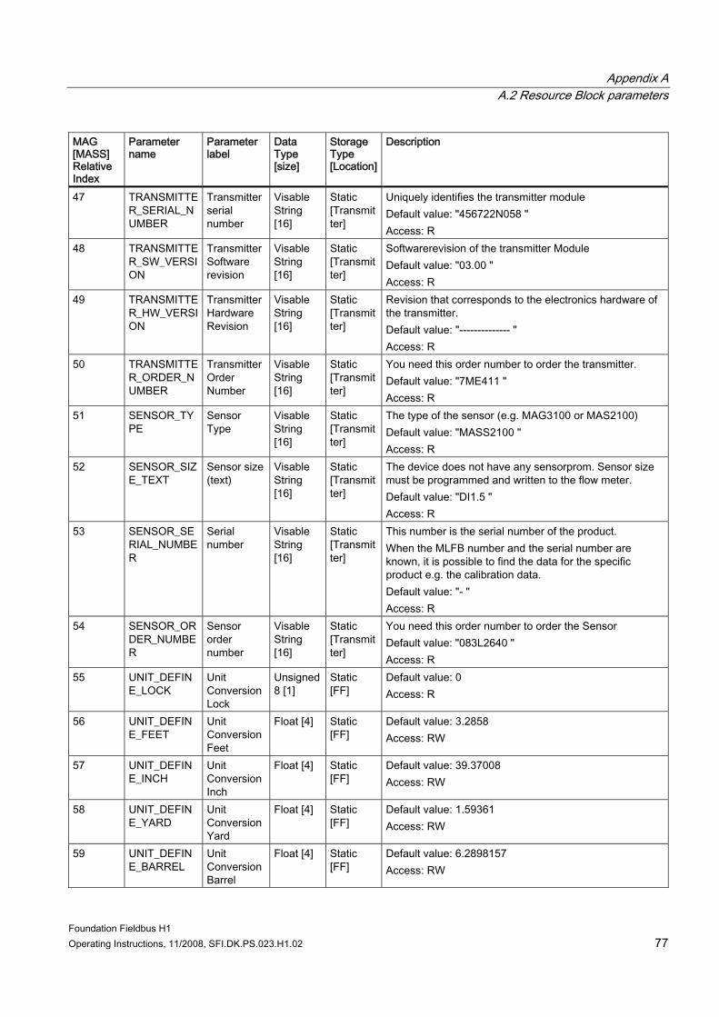
Appendix A A.2 Resource Block parameters
Foundation Fieldbus H1 Operating Instructions, 11/2008, SFI.DK.PS.023.H1.02 77
MAG [MASS] Relative Index
Parameter name
Parameter label
Data Type [size]
Storage Type [Location]
Description
47 TRANSMITTER_SERIAL_NUMBER
Transmitter serial number
Visable String [16]
Static [Transmitter]
Uniquely identifies the transmitter module Default value: "456722N058 " Access: R
48 TRANSMITTER_SW_VERSION
Transmitter Software revision
Visable String [16]
Static [Transmitter]
Softwarerevision of the transmitter Module Default value: "03.00 " Access: R
49 TRANSMITTER_HW_VERSION
Transmitter Hardware Revision
Visable String [16]
Static [Transmitter]
Revision that corresponds to the electronics hardware of the transmitter. Default value: "-------------- " Access: R
50 TRANSMITTER_ORDER_NUMBER
Transmitter Order Number
Visable String [16]
Static [Transmitter]
You need this order number to order the transmitter. Default value: "7ME411 " Access: R
51 SENSOR_TYPE
Sensor Type
Visable String [16]
Static [Transmitter]
The type of the sensor (e.g. MAG3100 or MAS2100) Default value: "MASS2100 " Access: R
52 SENSOR_SIZE_TEXT
Sensor size (text)
Visable String [16]
Static [Transmitter]
The device does not have any sensorprom. Sensor size must be programmed and written to the flow meter. Default value: "DI1.5 " Access: R
53 SENSOR_SERIAL_NUMBER
Serial number
Visable String [16]
Static [Transmitter]
This number is the serial number of the product. When the MLFB number and the serial number are known, it is possible to find the data for the specific product e.g. the calibration data. Default value: "- " Access: R
54 SENSOR_ORDER_NUMBER
Sensor order number
Visable String [16]
Static [Transmitter]
You need this order number to order the Sensor Default value: "083L2640 " Access: R
55 UNIT_DEFINE_LOCK
Unit Conversion Lock
Unsigned 8 [1]
Static [FF]
Default value: 0 Access: R
56 UNIT_DEFINE_FEET
Unit Conversion Feet
Float [4] Static [FF]
Default value: 3.2858 Access: RW
57 UNIT_DEFINE_INCH
Unit Conversion Inch
Float [4] Static [FF]
Default value: 39.37008 Access: RW
58 UNIT_DEFINE_YARD
Unit Conversion Yard
Float [4] Static [FF]
Default value: 1.59361 Access: RW
59 UNIT_DEFINE_BARREL
Unit Conversion Barrel
Float [4] Static [FF]
Default value: 6.2898157 Access: RW
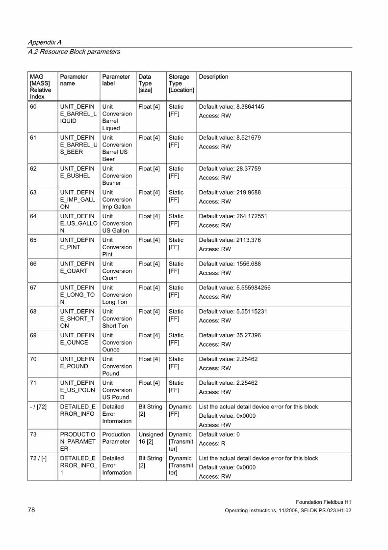
Appendix A A.2 Resource Block parameters
Foundation Fieldbus H1 78 Operating Instructions, 11/2008, SFI.DK.PS.023.H1.02
MAG [MASS] Relative Index
Parameter name
Parameter label
Data Type [size]
Storage Type [Location]
Description
60 UNIT_DEFINE_BARREL_LIQUID
Unit Conversion Barrel Liqued
Float [4] Static [FF]
Default value: 8.3864145 Access: RW
61 UNIT_DEFINE_BARREL_US_BEER
Unit Conversion Barrel US Beer
Float [4] Static [FF]
Default value: 8.521679 Access: RW
62 UNIT_DEFINE_BUSHEL
Unit Conversion Busher
Float [4] Static [FF]
Default value: 28.37759 Access: RW
63 UNIT_DEFINE_IMP_GALLON
Unit Conversion Imp Gallon
Float [4] Static [FF]
Default value: 219.9688 Access: RW
64 UNIT_DEFINE_US_GALLON
Unit Conversion US Gallon
Float [4] Static [FF]
Default value: 264.172551 Access: RW
65 UNIT_DEFINE_PINT
Unit Conversion Pint
Float [4] Static [FF]
Default value: 2113.376 Access: RW
66 UNIT_DEFINE_QUART
Unit Conversion Quart
Float [4] Static [FF]
Default value: 1556.688 Access: RW
67 UNIT_DEFINE_LONG_TON
Unit Conversion Long Ton
Float [4] Static [FF]
Default value: 5.555984256 Access: RW
68 UNIT_DEFINE_SHORT_TON
Unit Conversion Short Ton
Float [4] Static [FF]
Default value: 5.55115231 Access: RW
69 UNIT_DEFINE_OUNCE
Unit Conversion Ounce
Float [4] Static [FF]
Default value: 35.27396 Access: RW
70 UNIT_DEFINE_POUND
Unit Conversion Pound
Float [4] Static [FF]
Default value: 2.25462 Access: RW
71 UNIT_DEFINE_US_POUND
Unit Conversion US Pound
Float [4] Static [FF]
Default value: 2.25462 Access: RW
- / [72] DETAILED_ERROR_INFO
Detailed Error Information
Bit String [2]
Dynamic [FF]
List the actual detail device error for this block Default value: 0x0000 Access: RW
73 PRODUCTION_PARAMETER
Production Parameter
Unsigned 16 [2]
Dynamic [Transmitter]
Default value: 0 Access: R
72 / [-] DETAILED_ERROR_INFO_1
Detailed Error Information
Bit String [2]
Dynamic [Transmitter]
List the actual detail device error for this block Default value: 0x0000 Access: RW
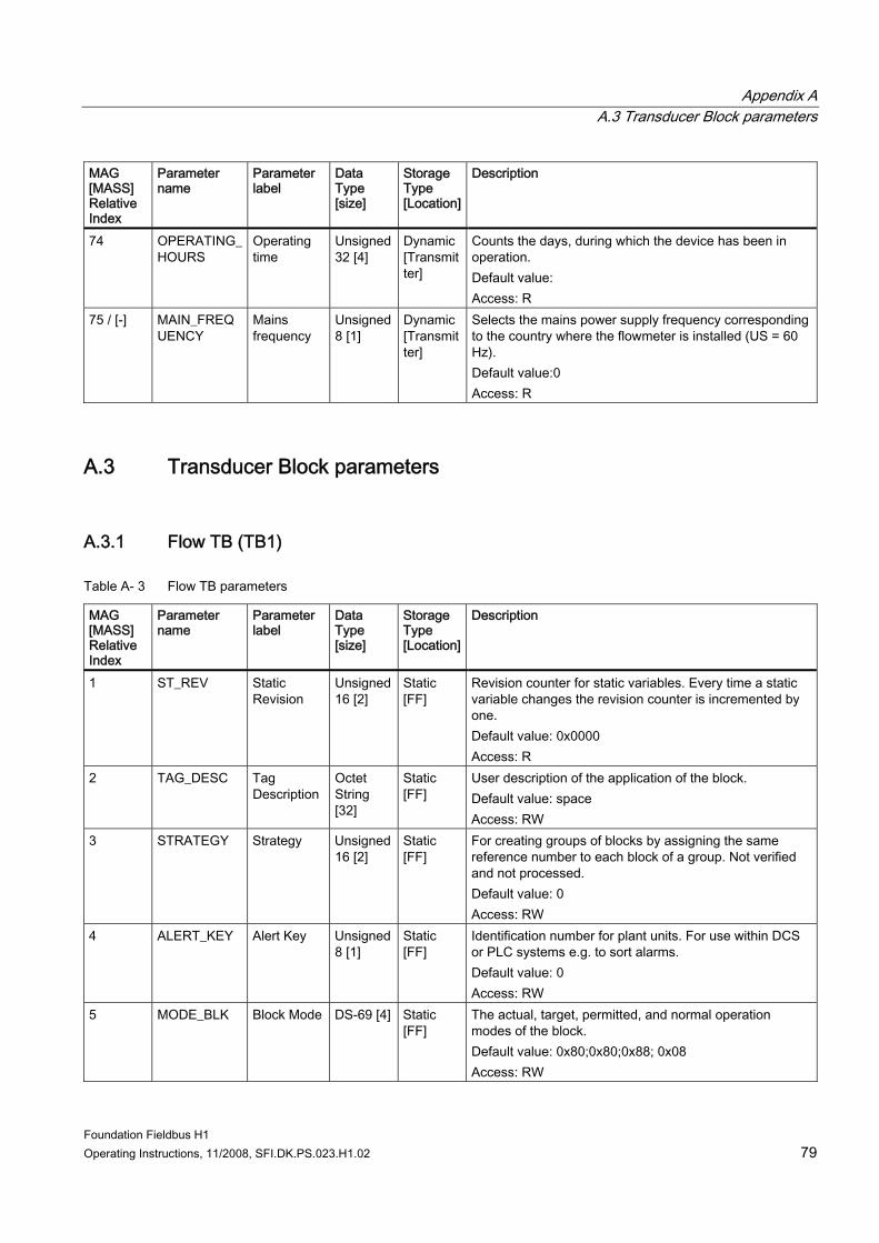
Appendix A A.3 Transducer Block parameters
Foundation Fieldbus H1 Operating Instructions, 11/2008, SFI.DK.PS.023.H1.02 79
MAG [MASS] Relative Index
Parameter name
Parameter label
Data Type [size]
Storage Type [Location]
Description
74 OPERATING_HOURS
Operating time
Unsigned 32 [4]
Dynamic [Transmitter]
Counts the days, during which the device has been in operation. Default value: Access: R
75 / [-] MAIN_FREQUENCY
Mains frequency
Unsigned 8 [1]
Dynamic [Transmitter]
Selects the mains power supply frequency corresponding to the country where the flowmeter is installed (US = 60 Hz). Default value:0 Access: R
A.3 Transducer Block parameters
A.3.1 Flow TB (TB1)
Table A- 3 Flow TB parameters
MAG [MASS] Relative Index
Parameter name
Parameter label
Data Type [size]
Storage Type [Location]
Description
1 ST_REV Static Revision
Unsigned 16 [2]
Static [FF]
Revision counter for static variables. Every time a static variable changes the revision counter is incremented by one. Default value: 0x0000 Access: R
2 TAG_DESC Tag Description
Octet String [32]
Static [FF]
User description of the application of the block. Default value: space Access: RW
3 STRATEGY Strategy Unsigned 16 [2]
Static [FF]
For creating groups of blocks by assigning the same reference number to each block of a group. Not verified and not processed. Default value: 0 Access: RW
4 ALERT_KEY Alert Key Unsigned 8 [1]
Static [FF]
Identification number for plant units. For use within DCS or PLC systems e.g. to sort alarms. Default value: 0 Access: RW
5 MODE_BLK Block Mode DS-69 [4] Static [FF]
The actual, target, permitted, and normal operation modes of the block. Default value: 0x80;0x80;0x88; 0x08 Access: RW
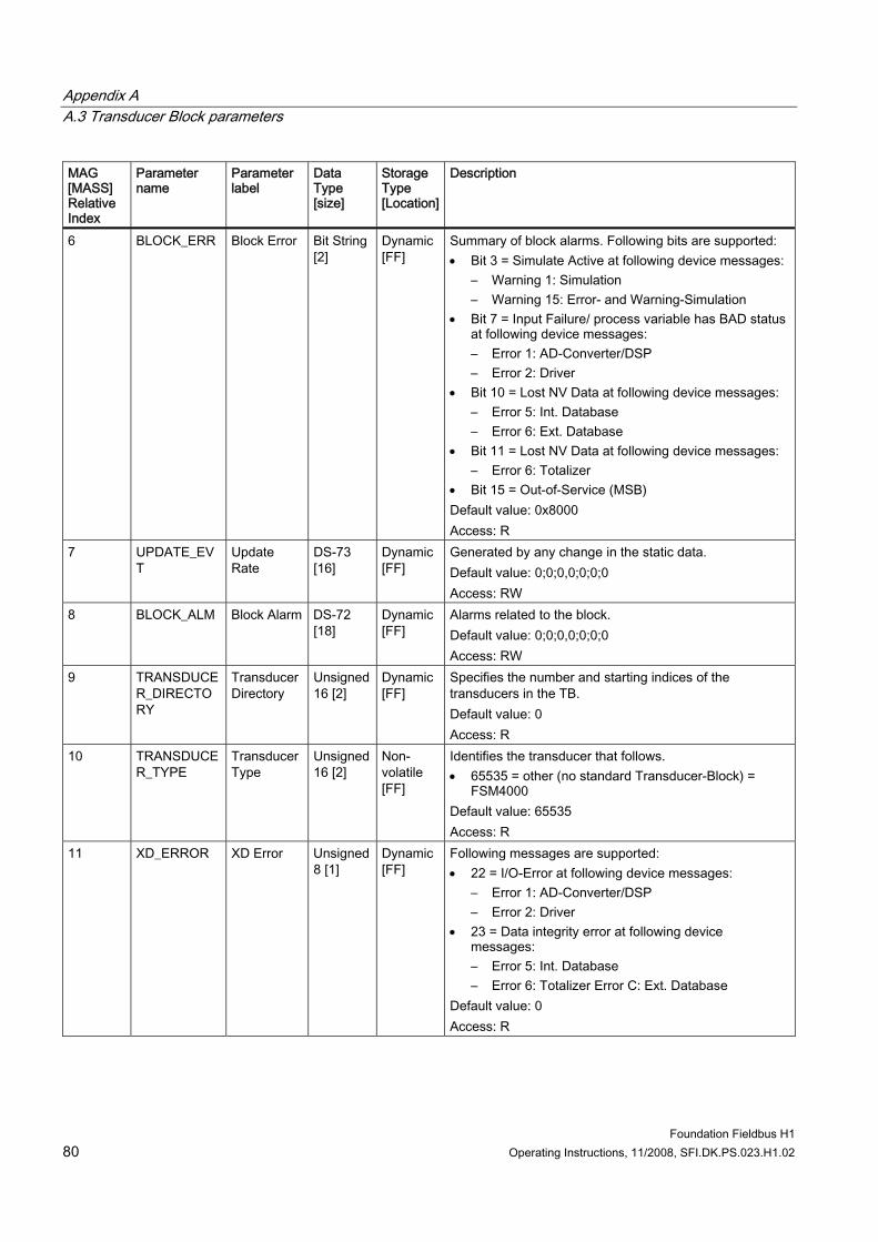
Appendix A A.3 Transducer Block parameters
Foundation Fieldbus H1 80 Operating Instructions, 11/2008, SFI.DK.PS.023.H1.02
MAG [MASS] Relative Index
Parameter name
Parameter label
Data Type [size]
Storage Type [Location]
Description
6 BLOCK_ERR Block Error Bit String [2]
Dynamic [FF]
Summary of block alarms. Following bits are supported: • Bit 3 = Simulate Active at following device messages:
– Warning 1: Simulation – Warning 15: Error- and Warning-Simulation
• Bit 7 = Input Failure/ process variable has BAD status at following device messages: – Error 1: AD-Converter/DSP – Error 2: Driver
• Bit 10 = Lost NV Data at following device messages: – Error 5: Int. Database – Error 6: Ext. Database
• Bit 11 = Lost NV Data at following device messages: – Error 6: Totalizer
• Bit 15 = Out-of-Service (MSB) Default value: 0x8000 Access: R
7 UPDATE_EVT
Update Rate
DS-73 [16]
Dynamic [FF]
Generated by any change in the static data. Default value: 0;0;0,0;0;0;0 Access: RW
8 BLOCK_ALM Block Alarm DS-72 [18]
Dynamic [FF]
Alarms related to the block. Default value: 0;0;0,0;0;0;0 Access: RW
9 TRANSDUCER_DIRECTORY
Transducer Directory
Unsigned 16 [2]
Dynamic [FF]
Specifies the number and starting indices of the transducers in the TB. Default value: 0 Access: R
10 TRANSDUCER_TYPE
Transducer Type
Unsigned 16 [2]
Non-volatile [FF]
Identifies the transducer that follows. • 65535 = other (no standard Transducer-Block) =
FSM4000 Default value: 65535 Access: R
11 XD_ERROR XD Error Unsigned 8 [1]
Dynamic [FF]
Following messages are supported: • 22 = I/O-Error at following device messages:
– Error 1: AD-Converter/DSP – Error 2: Driver
• 23 = Data integrity error at following device messages: – Error 5: Int. Database – Error 6: Totalizer Error C: Ext. Database
Default value: 0 Access: R
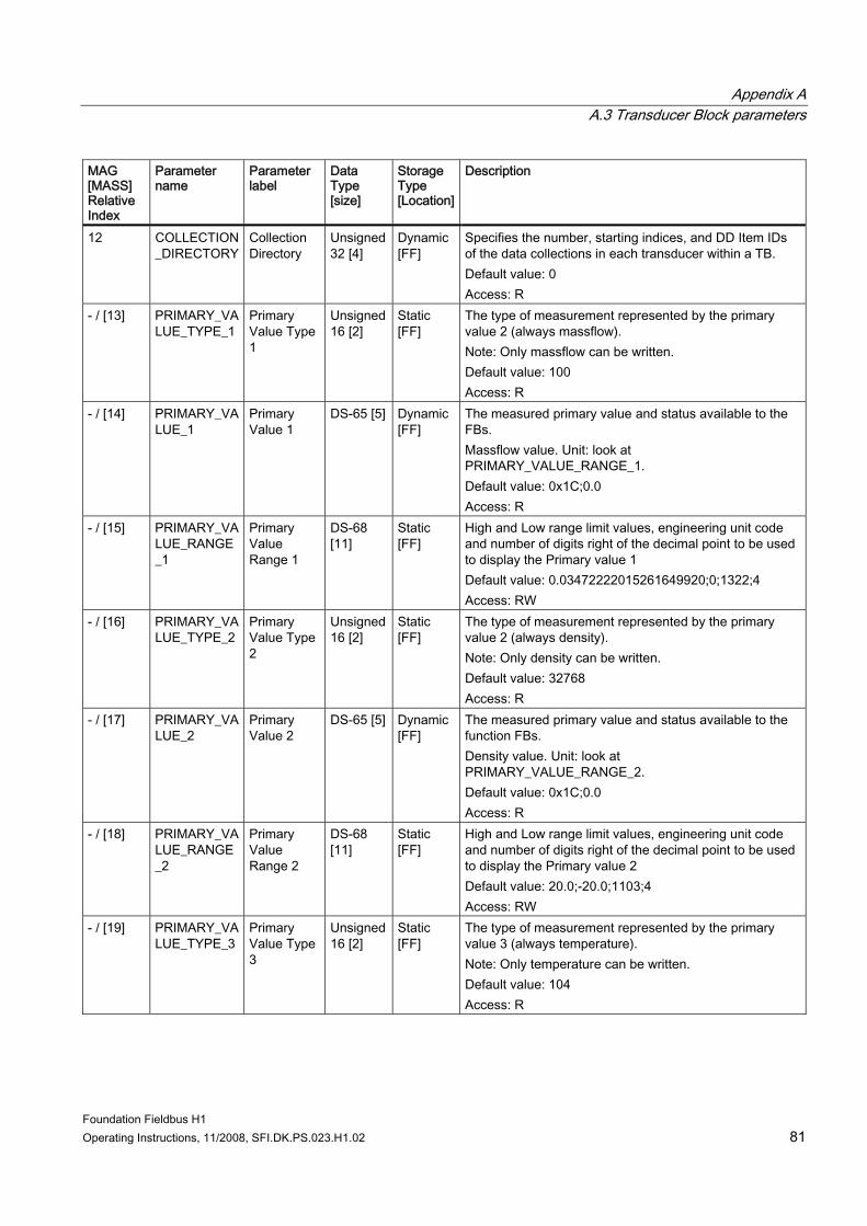
Appendix A A.3 Transducer Block parameters
Foundation Fieldbus H1 Operating Instructions, 11/2008, SFI.DK.PS.023.H1.02 81
MAG [MASS] Relative Index
Parameter name
Parameter label
Data Type [size]
Storage Type [Location]
Description
12 COLLECTION_DIRECTORY
Collection Directory
Unsigned 32 [4]
Dynamic [FF]
Specifies the number, starting indices, and DD Item IDs of the data collections in each transducer within a TB. Default value: 0 Access: R
- / [13] PRIMARY_VALUE_TYPE_1
Primary Value Type 1
Unsigned 16 [2]
Static [FF]
The type of measurement represented by the primary value 2 (always massflow). Note: Only massflow can be written. Default value: 100 Access: R
- / [14] PRIMARY_VALUE_1
Primary Value 1
DS-65 [5] Dynamic [FF]
The measured primary value and status available to the FBs. Massflow value. Unit: look at PRIMARY_VALUE_RANGE_1. Default value: 0x1C;0.0 Access: R
- / [15] PRIMARY_VALUE_RANGE_1
Primary Value Range 1
DS-68 [11]
Static [FF]
High and Low range limit values, engineering unit code and number of digits right of the decimal point to be used to display the Primary value 1 Default value: 0.03472222015261649920;0;1322;4 Access: RW
- / [16] PRIMARY_VALUE_TYPE_2
Primary Value Type 2
Unsigned 16 [2]
Static [FF]
The type of measurement represented by the primary value 2 (always density). Note: Only density can be written. Default value: 32768 Access: R
- / [17] PRIMARY_VALUE_2
Primary Value 2
DS-65 [5] Dynamic [FF]
The measured primary value and status available to the function FBs. Density value. Unit: look at PRIMARY_VALUE_RANGE_2. Default value: 0x1C;0.0 Access: R
- / [18] PRIMARY_VALUE_RANGE_2
Primary Value Range 2
DS-68 [11]
Static [FF]
High and Low range limit values, engineering unit code and number of digits right of the decimal point to be used to display the Primary value 2 Default value: 20.0;-20.0;1103;4 Access: RW
- / [19] PRIMARY_VALUE_TYPE_3
Primary Value Type 3
Unsigned 16 [2]
Static [FF]
The type of measurement represented by the primary value 3 (always temperature). Note: Only temperature can be written. Default value: 104 Access: R
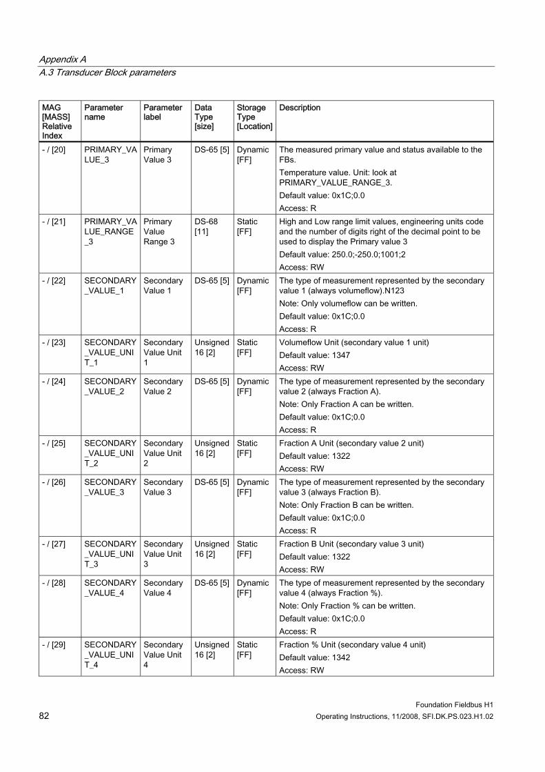
Appendix A A.3 Transducer Block parameters
Foundation Fieldbus H1 82 Operating Instructions, 11/2008, SFI.DK.PS.023.H1.02
MAG [MASS] Relative Index
Parameter name
Parameter label
Data Type [size]
Storage Type [Location]
Description
- / [20] PRIMARY_VALUE_3
Primary Value 3
DS-65 [5] Dynamic [FF]
The measured primary value and status available to the FBs. Temperature value. Unit: look at PRIMARY_VALUE_RANGE_3. Default value: 0x1C;0.0 Access: R
- / [21] PRIMARY_VALUE_RANGE_3
Primary Value Range 3
DS-68 [11]
Static [FF]
High and Low range limit values, engineering units code and the number of digits right of the decimal point to be used to display the Primary value 3 Default value: 250.0;-250.0;1001;2 Access: RW
- / [22] SECONDARY_VALUE_1
Secondary Value 1
DS-65 [5] Dynamic [FF]
The type of measurement represented by the secondary value 1 (always volumeflow).N123 Note: Only volumeflow can be written. Default value: 0x1C;0.0 Access: R
- / [23] SECONDARY_VALUE_UNIT_1
Secondary Value Unit 1
Unsigned 16 [2]
Static [FF]
Volumeflow Unit (secondary value 1 unit) Default value: 1347 Access: RW
- / [24] SECONDARY_VALUE_2
Secondary Value 2
DS-65 [5] Dynamic [FF]
The type of measurement represented by the secondary value 2 (always Fraction A). Note: Only Fraction A can be written. Default value: 0x1C;0.0 Access: R
- / [25] SECONDARY_VALUE_UNIT_2
Secondary Value Unit 2
Unsigned 16 [2]
Static [FF]
Fraction A Unit (secondary value 2 unit) Default value: 1322 Access: RW
- / [26] SECONDARY_VALUE_3
Secondary Value 3
DS-65 [5] Dynamic [FF]
The type of measurement represented by the secondary value 3 (always Fraction B). Note: Only Fraction B can be written. Default value: 0x1C;0.0 Access: R
- / [27] SECONDARY_VALUE_UNIT_3
Secondary Value Unit 3
Unsigned 16 [2]
Static [FF]
Fraction B Unit (secondary value 3 unit) Default value: 1322 Access: RW
- / [28] SECONDARY_VALUE_4
Secondary Value 4
DS-65 [5] Dynamic [FF]
The type of measurement represented by the secondary value 4 (always Fraction %). Note: Only Fraction % can be written. Default value: 0x1C;0.0 Access: R
- / [29] SECONDARY_VALUE_UNIT_4
Secondary Value Unit 4
Unsigned 16 [2]
Static [FF]
Fraction % Unit (secondary value 4 unit) Default value: 1342 Access: RW
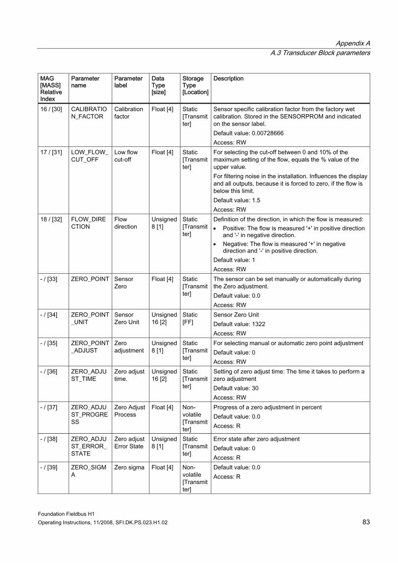
Appendix A A.3 Transducer Block parameters
Foundation Fieldbus H1 Operating Instructions, 11/2008, SFI.DK.PS.023.H1.02 83
MAG [MASS] Relative Index
Parameter name
Parameter label
Data Type [size]
Storage Type [Location]
Description
16 / [30] CALIBRATION_FACTOR
Calibration factor
Float [4] Static [Transmitter]
Sensor specific calibration factor from the factory wet calibration. Stored in the SENSORPROM and indicated on the sensor label. Default value: 0.00728666 Access: RW
17 / [31] LOW_FLOW_CUT_OFF
Low flow cut-off
Float [4] Static [Transmitter]
For selecting the cut-off between 0 and 10% of the maximum setting of the flow, equals the % value of the upper value. For filtering noise in the installation. Influences the display and all outputs, because it is forced to zero, if the flow is below this limit. Default value: 1.5 Access: RW
18 / [32] FLOW_DIRECTION
Flow direction
Unsigned 8 [1]
Static [Transmitter]
Definition of the direction, in which the flow is measured: • Positive: The flow is measured '+' in positive direction
and '-' in negative direction. • Negative: The flow is measured '+' in negative
direction and '-' in positive direction. Default value: 1 Access: RW
- / [33] ZERO_POINT Sensor Zero
Float [4] Static [Transmitter]
The sensor can be set manually or automatically during the Zero adjustment. Default value: 0.0 Access: RW
- / [34] ZERO_POINT_UNIT
Sensor Zero Unit
Unsigned 16 [2]
Static [FF]
Sensor Zero Unit Default value: 1322 Access: RW
- / [35] ZERO_POINT_ADJUST
Zero adjustment
Unsigned 8 [1]
Static [Transmitter]
For selecting manual or automatic zero point adjustment Default value: 0 Access: RW
- / [36] ZERO_ADJUST_TIME
Zero adjust time.
Unsigned 16 [2]
Static [Transmitter]
Setting of zero adjust time: The time it takes to perform a zero adjustment Default value: 30 Access: RW
- / [37] ZERO_ADJUST_PROGRESS
Zero Adjust Process
Float [4] Non-volatile [Transmitter]
Progress of a zero adjustment in percent Default value: 0.0 Access: R
- / [38] ZERO_ADJUST_ERROR_STATE
Zero adjust Error State
Unsigned 8 [1]
Static [Transmitter]
Error state after zero adjustment Default value: 0 Access: R
- / [39] ZERO_SIGMA
Zero sigma Float [4] Non-volatile [Transmitter]
Default value: 0.0 Access: R
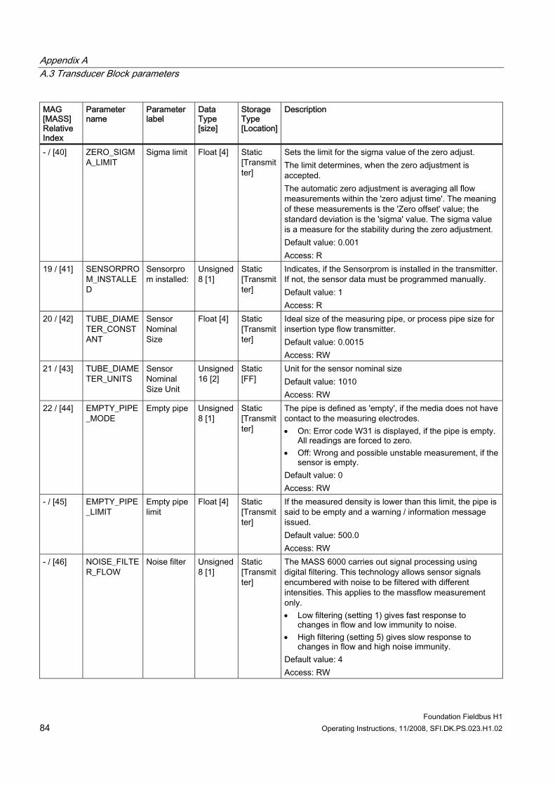
Appendix A A.3 Transducer Block parameters
Foundation Fieldbus H1 84 Operating Instructions, 11/2008, SFI.DK.PS.023.H1.02
MAG [MASS] Relative Index
Parameter name
Parameter label
Data Type [size]
Storage Type [Location]
Description
- / [40] ZERO_SIGMA_LIMIT
Sigma limit Float [4] Static [Transmitter]
Sets the limit for the sigma value of the zero adjust. The limit determines, when the zero adjustment is accepted. The automatic zero adjustment is averaging all flow measurements within the 'zero adjust time'. The meaning of these measurements is the 'Zero offset' value; the standard deviation is the 'sigma' value. The sigma value is a measure for the stability during the zero adjustment. Default value: 0.001 Access: R
19 / [41] SENSORPROM_INSTALLED
Sensorprom installed:
Unsigned 8 [1]
Static [Transmitter]
Indicates, if the Sensorprom is installed in the transmitter. If not, the sensor data must be programmed manually. Default value: 1 Access: R
20 / [42] TUBE_DIAMETER_CONSTANT
Sensor Nominal Size
Float [4] Static [Transmitter]
Ideal size of the measuring pipe, or process pipe size for insertion type flow transmitter. Default value: 0.0015 Access: RW
21 / [43] TUBE_DIAMETER_UNITS
Sensor Nominal Size Unit
Unsigned 16 [2]
Static [FF]
Unit for the sensor nominal size Default value: 1010 Access: RW
22 / [44] EMPTY_PIPE_MODE
Empty pipe Unsigned 8 [1]
Static [Transmitter]
The pipe is defined as 'empty', if the media does not have contact to the measuring electrodes. • On: Error code W31 is displayed, if the pipe is empty.
All readings are forced to zero. • Off: Wrong and possible unstable measurement, if the
sensor is empty. Default value: 0 Access: RW
- / [45] EMPTY_PIPE_LIMIT
Empty pipe limit
Float [4] Static [Transmitter]
If the measured density is lower than this limit, the pipe is said to be empty and a warning / information message issued. Default value: 500.0 Access: RW
- / [46] NOISE_FILTER_FLOW
Noise filter Unsigned 8 [1]
Static [Transmitter]
The MASS 6000 carries out signal processing using digital filtering. This technology allows sensor signals encumbered with noise to be filtered with different intensities. This applies to the massflow measurement only. • Low filtering (setting 1) gives fast response to
changes in flow and low immunity to noise. • High filtering (setting 5) gives slow response to
changes in flow and high noise immunity. Default value: 4 Access: RW
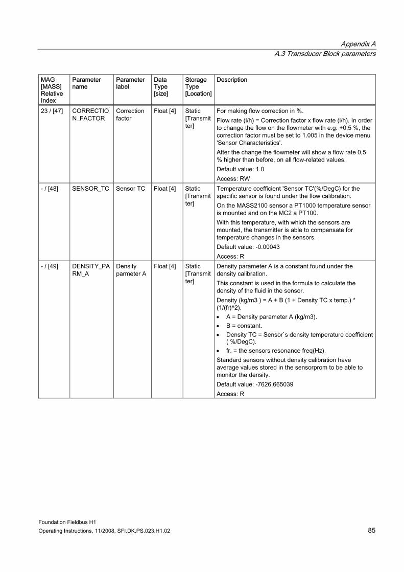
Appendix A A.3 Transducer Block parameters
Foundation Fieldbus H1 Operating Instructions, 11/2008, SFI.DK.PS.023.H1.02 85
MAG [MASS] Relative Index
Parameter name
Parameter label
Data Type [size]
Storage Type [Location]
Description
23 / [47] CORRECTION_FACTOR
Correction factor
Float [4] Static [Transmitter]
For making flow correction in %. Flow rate (l/h) = Correction factor x flow rate (l/h). In order to change the flow on the flowmeter with e.g. +0,5 %, the correction factor must be set to 1.005 in the device menu 'Sensor Characteristics'. After the change the flowmeter will show a flow rate 0,5 % higher than before, on all flow-related values. Default value: 1.0 Access: RW
- / [48] SENSOR_TC Sensor TC Float [4] Static [Transmitter]
Temperature coefficient 'Sensor TC'(%/DegC) for the specific sensor is found under the flow calibration. On the MASS2100 sensor a PT1000 temperature sensor is mounted and on the MC2 a PT100. With this temperature, with which the sensors are mounted, the transmitter is able to compensate for temperature changes in the sensors. Default value: -0.00043 Access: R
- / [49] DENSITY_PARM_A
Density parmeter A
Float [4] Static [Transmitter]
Density parameter A is a constant found under the density calibration. This constant is used in the formula to calculate the density of the fluid in the sensor. Density (kg/m3 ) = A + B (1 + Density TC x temp.) * (1/(fr)^2). • A = Density parameter A (kg/m3). • B = constant. • Density TC = Sensor`s density temperature coefficient
( %/DegC). • fr. = the sensors resonance freq(Hz). Standard sensors without density calibration have average values stored in the sensorprom to be able to monitor the density. Default value: -7626.665039 Access: R
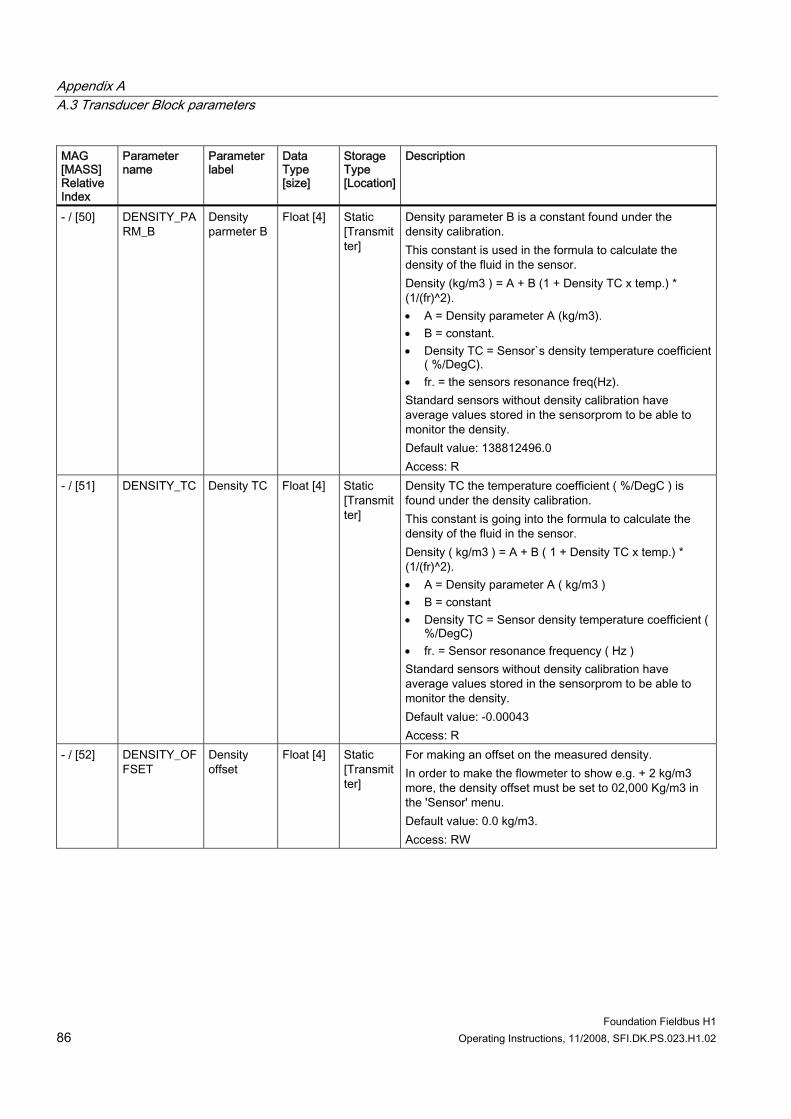
Appendix A A.3 Transducer Block parameters
Foundation Fieldbus H1 86 Operating Instructions, 11/2008, SFI.DK.PS.023.H1.02
MAG [MASS] Relative Index
Parameter name
Parameter label
Data Type [size]
Storage Type [Location]
Description
- / [50] DENSITY_PARM_B
Density parmeter B
Float [4] Static [Transmitter]
Density parameter B is a constant found under the density calibration. This constant is used in the formula to calculate the density of the fluid in the sensor. Density (kg/m3 ) = A + B (1 + Density TC x temp.) * (1/(fr)^2). • A = Density parameter A (kg/m3). • B = constant. • Density TC = Sensor`s density temperature coefficient
( %/DegC). • fr. = the sensors resonance freq(Hz). Standard sensors without density calibration have average values stored in the sensorprom to be able to monitor the density. Default value: 138812496.0 Access: R
- / [51] DENSITY_TC Density TC Float [4] Static [Transmitter]
Density TC the temperature coefficient ( %/DegC ) is found under the density calibration. This constant is going into the formula to calculate the density of the fluid in the sensor. Density ( kg/m3 ) = A + B ( 1 + Density TC x temp.) * (1/(fr)^2). • A = Density parameter A ( kg/m3 ) • B = constant • Density TC = Sensor density temperature coefficient (
%/DegC) • fr. = Sensor resonance frequency ( Hz ) Standard sensors without density calibration have average values stored in the sensorprom to be able to monitor the density. Default value: -0.00043 Access: R
- / [52] DENSITY_OFFSET
Density offset
Float [4] Static [Transmitter]
For making an offset on the measured density. In order to make the flowmeter to show e.g. + 2 kg/m3 more, the density offset must be set to 02,000 Kg/m3 in the 'Sensor' menu. Default value: 0.0 kg/m3. Access: RW
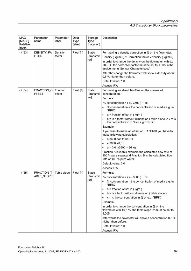
Appendix A A.3 Transducer Block parameters
Foundation Fieldbus H1 Operating Instructions, 11/2008, SFI.DK.PS.023.H1.02 87
MAG [MASS] Relative Index
Parameter name
Parameter label
Data Type [size]
Storage Type [Location]
Description
- / [53] DENSITY_FACTOR
Density factor
Float [4] Static [Transmitter]
For making a density correction in % on the flowmeter. Density ( kg/m3 ) = Correction factor x density ( kg/m3 ). In order to change the density on the flowmeter with e.g. +0,5 %, the correction factor must be set to 1.005 in the device menu 'Sensor Characteristics' After the change the flowmeter will show a density about 0,5 % higher than before. Default value: 1.0 Access: RW
- / [54] FRACTION_OFFSET
Fraction offset
Float [4] Static [Transmitter]
For making an absolute offset on the measured concentration. Formula: % concentration = ( a / 3600 ) + bx • % concentration = the concentration of media e.g. in
°BRIX • a = fraction offset in ( kg/h ) • b = is a factor without dimension ( table slope )z x = is
the concentration in % or e.g. °BRIX Example: If you want to make an offset on + 1 °BRIX you have to make following calculation: • a/3600 has to be 1%. • a/3600 =0,01 • a = 0,01x3600 = 36 kg Fraction A is in this example the calculated flow rate of 100 % pure sugar,and Fraction B is the calculated flow rate of 100 % pure water. Default value: 0.0 Access: RW
- / [55] FRACTION_TABLE_SLOPE
Table slope Float [4] Static [Transmitter]
Formula: % concentration = ( a / 3600 ) + bx • % concentration = the concentration of media e.g. in
°BRIX • a = fraction offset in ( kg/h ) • b = is a factor without dimension ( table slope ) • x = is the concentration in % or e.g. °BRIX Example: In order to change the concentration in % on the flowmeter with +0,5 %, the table slope 'b' must be set to 1.005. Afterwards the flowmeter will show a concentration 0,5 % higher than before. Default value: 1.0 Access: RW
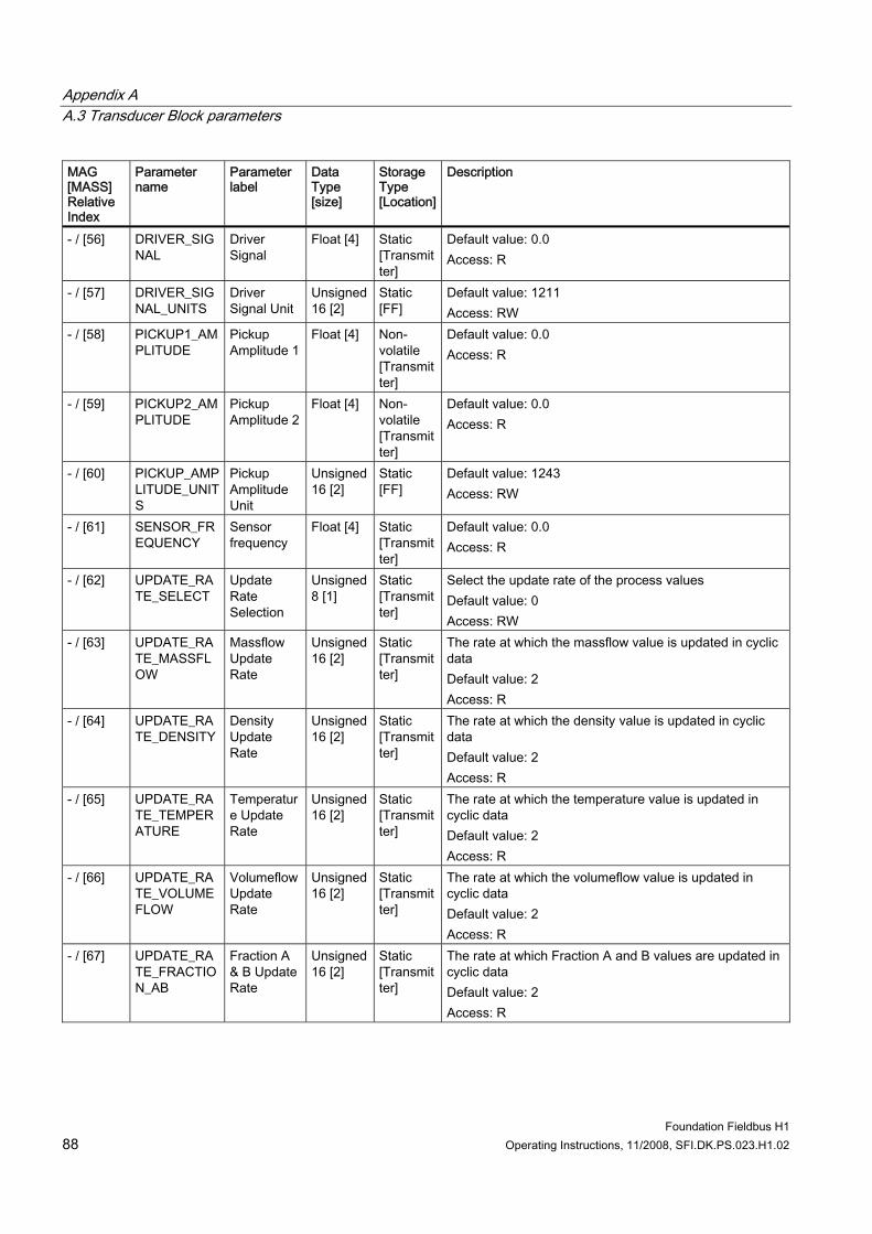
Appendix A A.3 Transducer Block parameters
Foundation Fieldbus H1 88 Operating Instructions, 11/2008, SFI.DK.PS.023.H1.02
MAG [MASS] Relative Index
Parameter name
Parameter label
Data Type [size]
Storage Type [Location]
Description
- / [56] DRIVER_SIGNAL
Driver Signal
Float [4] Static [Transmitter]
Default value: 0.0 Access: R
- / [57] DRIVER_SIGNAL_UNITS
Driver Signal Unit
Unsigned 16 [2]
Static [FF]
Default value: 1211 Access: RW
- / [58] PICKUP1_AMPLITUDE
Pickup Amplitude 1
Float [4] Non-volatile [Transmitter]
Default value: 0.0 Access: R
- / [59] PICKUP2_AMPLITUDE
Pickup Amplitude 2
Float [4] Non-volatile [Transmitter]
Default value: 0.0 Access: R
- / [60] PICKUP_AMPLITUDE_UNITS
Pickup Amplitude Unit
Unsigned 16 [2]
Static [FF]
Default value: 1243 Access: RW
- / [61] SENSOR_FREQUENCY
Sensor frequency
Float [4] Static [Transmitter]
Default value: 0.0 Access: R
- / [62] UPDATE_RATE_SELECT
Update Rate Selection
Unsigned 8 [1]
Static [Transmitter]
Select the update rate of the process values Default value: 0 Access: RW
- / [63] UPDATE_RATE_MASSFLOW
Massflow Update Rate
Unsigned 16 [2]
Static [Transmitter]
The rate at which the massflow value is updated in cyclic data Default value: 2 Access: R
- / [64] UPDATE_RATE_DENSITY
Density Update Rate
Unsigned 16 [2]
Static [Transmitter]
The rate at which the density value is updated in cyclic data Default value: 2 Access: R
- / [65] UPDATE_RATE_TEMPERATURE
Temperature Update Rate
Unsigned 16 [2]
Static [Transmitter]
The rate at which the temperature value is updated in cyclic data Default value: 2 Access: R
- / [66] UPDATE_RATE_VOLUMEFLOW
Volumeflow Update Rate
Unsigned 16 [2]
Static [Transmitter]
The rate at which the volumeflow value is updated in cyclic data Default value: 2 Access: R
- / [67] UPDATE_RATE_FRACTION_AB
Fraction A & B Update Rate
Unsigned 16 [2]
Static [Transmitter]
The rate at which Fraction A and B values are updated in cyclic data Default value: 2 Access: R
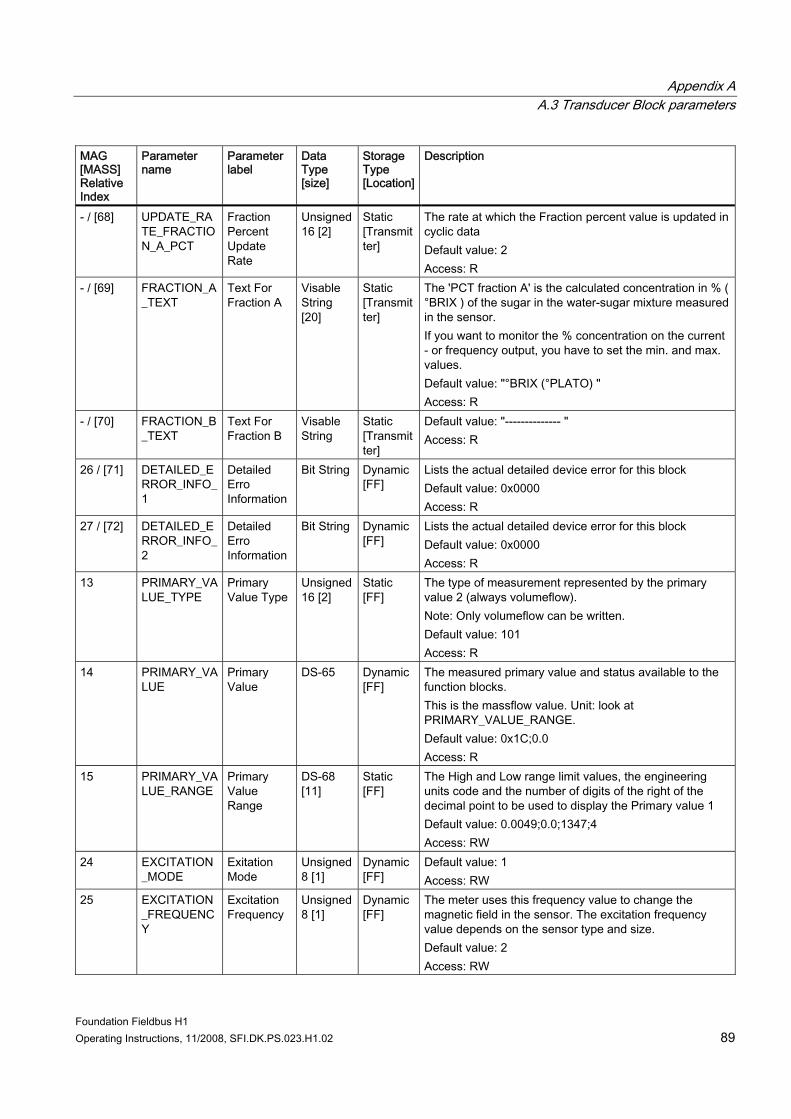
Appendix A A.3 Transducer Block parameters
Foundation Fieldbus H1 Operating Instructions, 11/2008, SFI.DK.PS.023.H1.02 89
MAG [MASS] Relative Index
Parameter name
Parameter label
Data Type [size]
Storage Type [Location]
Description
- / [68] UPDATE_RATE_FRACTION_A_PCT
Fraction Percent Update Rate
Unsigned 16 [2]
Static [Transmitter]
The rate at which the Fraction percent value is updated in cyclic data Default value: 2 Access: R
- / [69] FRACTION_A_TEXT
Text For Fraction A
Visable String [20]
Static [Transmitter]
The 'PCT fraction A' is the calculated concentration in % ( °BRIX ) of the sugar in the water-sugar mixture measured in the sensor. If you want to monitor the % concentration on the current - or frequency output, you have to set the min. and max. values. Default value: "°BRIX (°PLATO) " Access: R
- / [70] FRACTION_B_TEXT
Text For Fraction B
Visable String
Static [Transmitter]
Default value: "-------------- " Access: R
26 / [71] DETAILED_ERROR_INFO_1
Detailed Erro Information
Bit String Dynamic [FF]
Lists the actual detailed device error for this block Default value: 0x0000 Access: R
27 / [72] DETAILED_ERROR_INFO_2
Detailed Erro Information
Bit String Dynamic [FF]
Lists the actual detailed device error for this block Default value: 0x0000 Access: R
13 PRIMARY_VALUE_TYPE
Primary Value Type
Unsigned 16 [2]
Static [FF]
The type of measurement represented by the primary value 2 (always volumeflow). Note: Only volumeflow can be written. Default value: 101 Access: R
14 PRIMARY_VALUE
Primary Value
DS-65 Dynamic [FF]
The measured primary value and status available to the function blocks. This is the massflow value. Unit: look at PRIMARY_VALUE_RANGE. Default value: 0x1C;0.0 Access: R
15 PRIMARY_VALUE_RANGE
Primary Value Range
DS-68 [11]
Static [FF]
The High and Low range limit values, the engineering units code and the number of digits of the right of the decimal point to be used to display the Primary value 1 Default value: 0.0049;0.0;1347;4 Access: RW
24 EXCITATION_MODE
Exitation Mode
Unsigned 8 [1]
Dynamic [FF]
Default value: 1 Access: RW
25 EXCITATION_FREQUENCY
Excitation Frequency
Unsigned 8 [1]
Dynamic [FF]
The meter uses this frequency value to change the magnetic field in the sensor. The excitation frequency value depends on the sensor type and size. Default value: 2 Access: RW
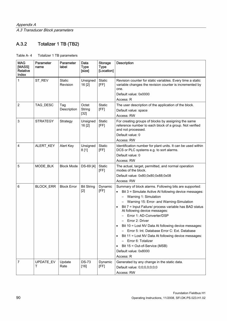
Appendix A A.3 Transducer Block parameters
Foundation Fieldbus H1 90 Operating Instructions, 11/2008, SFI.DK.PS.023.H1.02
A.3.2 Totalizer 1 TB (TB2)
Table A- 4 Totalizer 1 TB parameters
MAG [MASS] Relative Index
Parameter name
Parameter label
Data Type [size]
Storage Type [Location]
Description
1 ST_REV Static Revision
Unsigned 16 [2]
Static [FF]
Revision counter for static variables. Every time a static variable changes the revision counter is incremented by one. Default value: 0x0000 Access: R
2 TAG_DESC Tag Description
Octet String [32]
Static [FF]
The user description of the application of the block. Default value: space Access: RW
3 STRATEGY Strategy Unsigned 16 [2]
Static [FF]
For creating groups of blocks by assigning the same reference number to each block of a group. Not verified and not processed. Default value: 0 Access: RW
4 ALERT_KEY Alert Key Unsigned 8 [1]
Static [FF]
Identification number for plant units. It can be used within DCS or PLC systems e.g. to sort alarms. Default value: 0 Access: RW
5 MODE_BLK Block Mode DS-69 [4] Static [FF]
The actual, target, permitted, and normal operation modes of the block. Default value: 0x80;0x80;0x88;0x08 Access: RW
6 BLOCK_ERR Block Error Bit String [2]
Dynamic [FF]
Summary of block alarms. Following bits are supported: • Bit 3 = Simulate Active At following device messages:
– Warning 1: Simulation – Warning 15: Error- and Warning-Simulation
• Bit 7 = Input Failure/ process variable has BAD status At following device messages: – Error 1: AD-Converter/DSP – Error 2: Driver
• Bit 10 = Lost NV Data At following device messages: – Error 5: Int. Database Error C: Ext. Database
• Bit 11 = Lost NV Data At following device messages: – Error 6: Totalizer
• Bit 15 = Out-of-Service (MSB) Default value: 0x8000 Access: R
7 UPDATE_EVT
Update Rate
DS-73 [16]
Dynamic [FF]
Generated by any change in the static data. Default value: 0;0;0,0;0;0;0 Access: RW
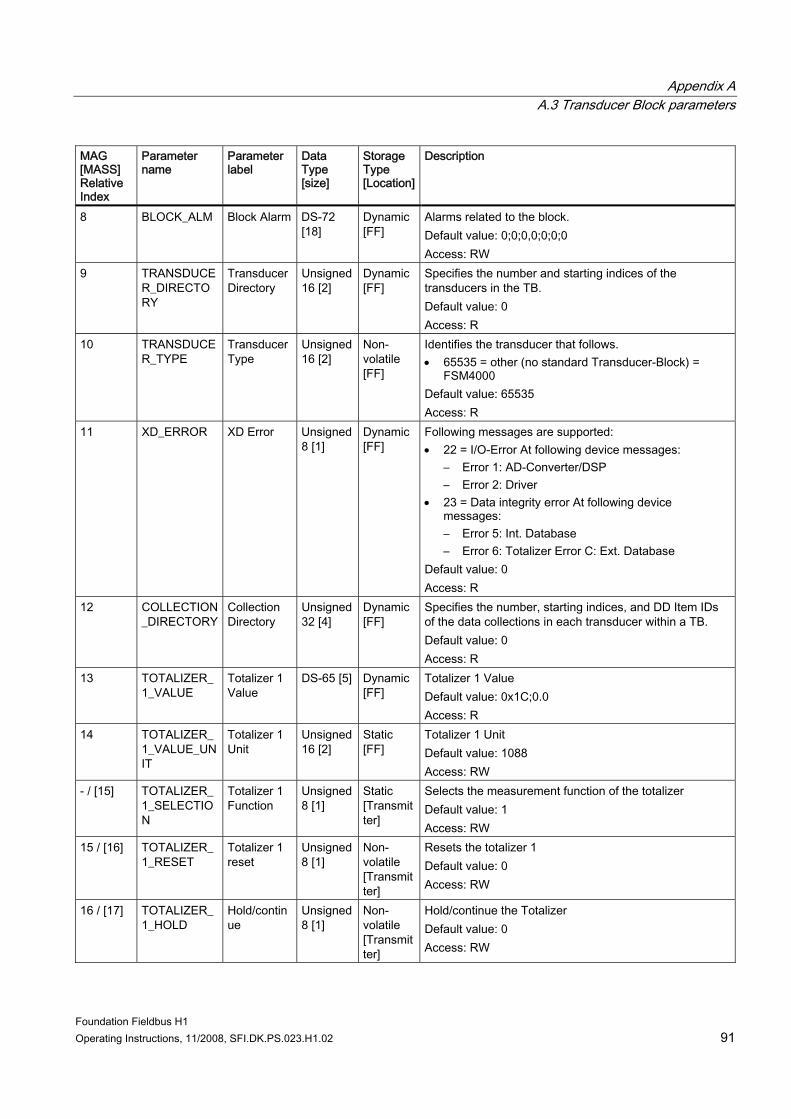
Appendix A A.3 Transducer Block parameters
Foundation Fieldbus H1 Operating Instructions, 11/2008, SFI.DK.PS.023.H1.02 91
MAG [MASS] Relative Index
Parameter name
Parameter label
Data Type [size]
Storage Type [Location]
Description
8 BLOCK_ALM Block Alarm DS-72 [18]
Dynamic [FF]
Alarms related to the block. Default value: 0;0;0,0;0;0;0 Access: RW
9 TRANSDUCER_DIRECTORY
Transducer Directory
Unsigned 16 [2]
Dynamic [FF]
Specifies the number and starting indices of the transducers in the TB. Default value: 0 Access: R
10 TRANSDUCER_TYPE
Transducer Type
Unsigned 16 [2]
Non-volatile [FF]
Identifies the transducer that follows. • 65535 = other (no standard Transducer-Block) =
FSM4000 Default value: 65535 Access: R
11 XD_ERROR XD Error Unsigned 8 [1]
Dynamic [FF]
Following messages are supported: • 22 = I/O-Error At following device messages:
– Error 1: AD-Converter/DSP – Error 2: Driver
• 23 = Data integrity error At following device messages: – Error 5: Int. Database – Error 6: Totalizer Error C: Ext. Database
Default value: 0 Access: R
12 COLLECTION_DIRECTORY
Collection Directory
Unsigned 32 [4]
Dynamic [FF]
Specifies the number, starting indices, and DD Item IDs of the data collections in each transducer within a TB. Default value: 0 Access: R
13 TOTALIZER_1_VALUE
Totalizer 1 Value
DS-65 [5] Dynamic [FF]
Totalizer 1 Value Default value: 0x1C;0.0 Access: R
14 TOTALIZER_1_VALUE_UNIT
Totalizer 1 Unit
Unsigned 16 [2]
Static [FF]
Totalizer 1 Unit Default value: 1088 Access: RW
- / [15] TOTALIZER_1_SELECTION
Totalizer 1 Function
Unsigned 8 [1]
Static [Transmitter]
Selects the measurement function of the totalizer Default value: 1 Access: RW
15 / [16] TOTALIZER_1_RESET
Totalizer 1 reset
Unsigned 8 [1]
Non-volatile [Transmitter]
Resets the totalizer 1 Default value: 0 Access: RW
16 / [17] TOTALIZER_1_HOLD
Hold/continue
Unsigned 8 [1]
Non-volatile [Transmitter]
Hold/continue the Totalizer Default value: 0 Access: RW
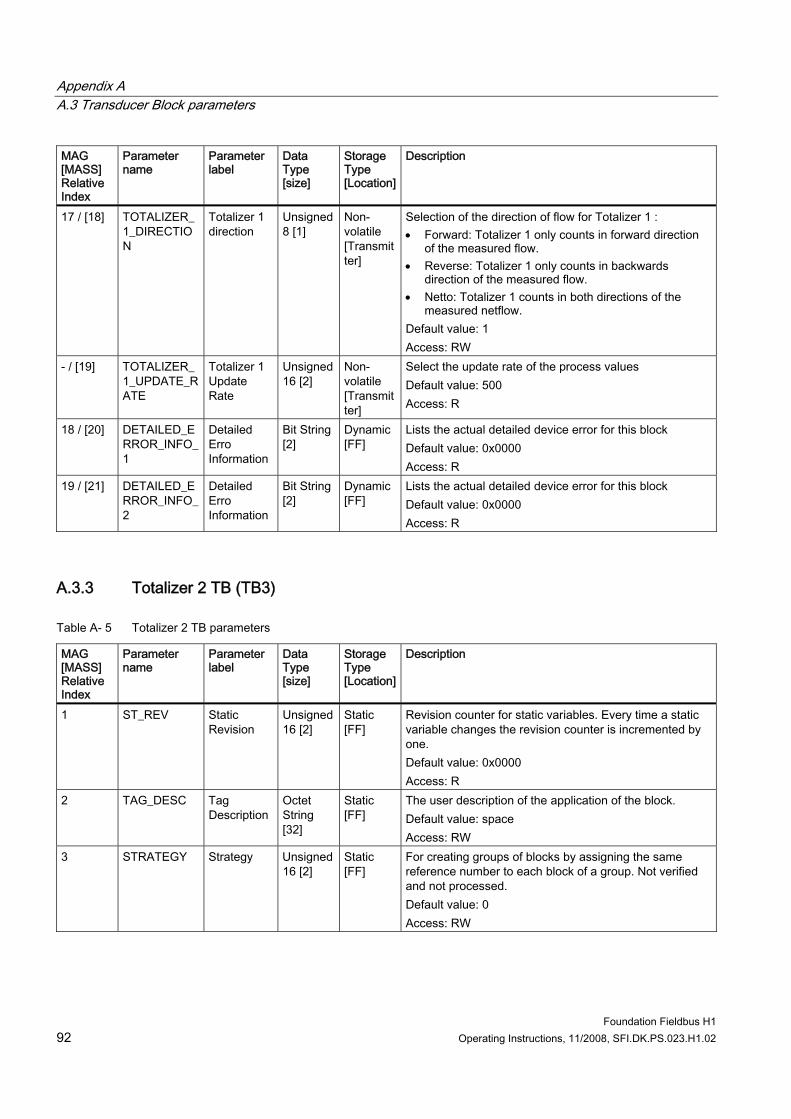
Appendix A A.3 Transducer Block parameters
Foundation Fieldbus H1 92 Operating Instructions, 11/2008, SFI.DK.PS.023.H1.02
MAG [MASS] Relative Index
Parameter name
Parameter label
Data Type [size]
Storage Type [Location]
Description
17 / [18] TOTALIZER_1_DIRECTION
Totalizer 1 direction
Unsigned 8 [1]
Non-volatile [Transmitter]
Selection of the direction of flow for Totalizer 1 : • Forward: Totalizer 1 only counts in forward direction
of the measured flow. • Reverse: Totalizer 1 only counts in backwards
direction of the measured flow. • Netto: Totalizer 1 counts in both directions of the
measured netflow. Default value: 1 Access: RW
- / [19] TOTALIZER_1_UPDATE_RATE
Totalizer 1 Update Rate
Unsigned 16 [2]
Non-volatile [Transmitter]
Select the update rate of the process values Default value: 500 Access: R
18 / [20] DETAILED_ERROR_INFO_1
Detailed Erro Information
Bit String [2]
Dynamic [FF]
Lists the actual detailed device error for this block Default value: 0x0000 Access: R
19 / [21] DETAILED_ERROR_INFO_2
Detailed Erro Information
Bit String [2]
Dynamic [FF]
Lists the actual detailed device error for this block Default value: 0x0000 Access: R
A.3.3 Totalizer 2 TB (TB3)
Table A- 5 Totalizer 2 TB parameters
MAG [MASS] Relative Index
Parameter name
Parameter label
Data Type [size]
Storage Type [Location]
Description
1 ST_REV Static Revision
Unsigned 16 [2]
Static [FF]
Revision counter for static variables. Every time a static variable changes the revision counter is incremented by one. Default value: 0x0000 Access: R
2 TAG_DESC Tag Description
Octet String [32]
Static [FF]
The user description of the application of the block. Default value: space Access: RW
3 STRATEGY Strategy Unsigned 16 [2]
Static [FF]
For creating groups of blocks by assigning the same reference number to each block of a group. Not verified and not processed. Default value: 0 Access: RW
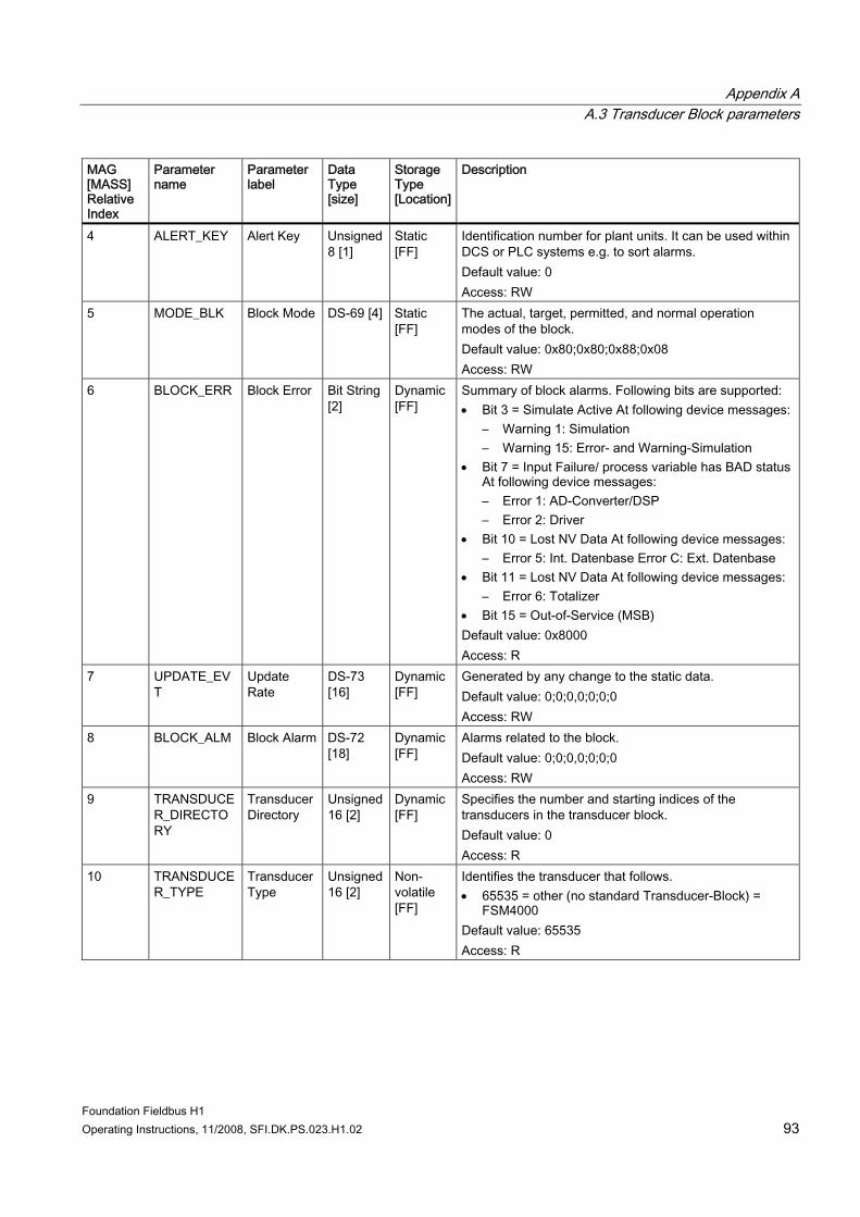
Appendix A A.3 Transducer Block parameters
Foundation Fieldbus H1 Operating Instructions, 11/2008, SFI.DK.PS.023.H1.02 93
MAG [MASS] Relative Index
Parameter name
Parameter label
Data Type [size]
Storage Type [Location]
Description
4 ALERT_KEY Alert Key Unsigned 8 [1]
Static [FF]
Identification number for plant units. It can be used within DCS or PLC systems e.g. to sort alarms. Default value: 0 Access: RW
5 MODE_BLK Block Mode DS-69 [4] Static [FF]
The actual, target, permitted, and normal operation modes of the block. Default value: 0x80;0x80;0x88;0x08 Access: RW
6 BLOCK_ERR Block Error Bit String [2]
Dynamic [FF]
Summary of block alarms. Following bits are supported: • Bit 3 = Simulate Active At following device messages:
– Warning 1: Simulation – Warning 15: Error- and Warning-Simulation
• Bit 7 = Input Failure/ process variable has BAD status At following device messages: – Error 1: AD-Converter/DSP – Error 2: Driver
• Bit 10 = Lost NV Data At following device messages: – Error 5: Int. Datenbase Error C: Ext. Datenbase
• Bit 11 = Lost NV Data At following device messages: – Error 6: Totalizer
• Bit 15 = Out-of-Service (MSB) Default value: 0x8000 Access: R
7 UPDATE_EVT
Update Rate
DS-73 [16]
Dynamic [FF]
Generated by any change to the static data. Default value: 0;0;0,0;0;0;0 Access: RW
8 BLOCK_ALM Block Alarm DS-72 [18]
Dynamic [FF]
Alarms related to the block. Default value: 0;0;0,0;0;0;0 Access: RW
9 TRANSDUCER_DIRECTORY
Transducer Directory
Unsigned 16 [2]
Dynamic [FF]
Specifies the number and starting indices of the transducers in the transducer block. Default value: 0 Access: R
10 TRANSDUCER_TYPE
Transducer Type
Unsigned 16 [2]
Non-volatile [FF]
Identifies the transducer that follows. • 65535 = other (no standard Transducer-Block) =
FSM4000 Default value: 65535 Access: R
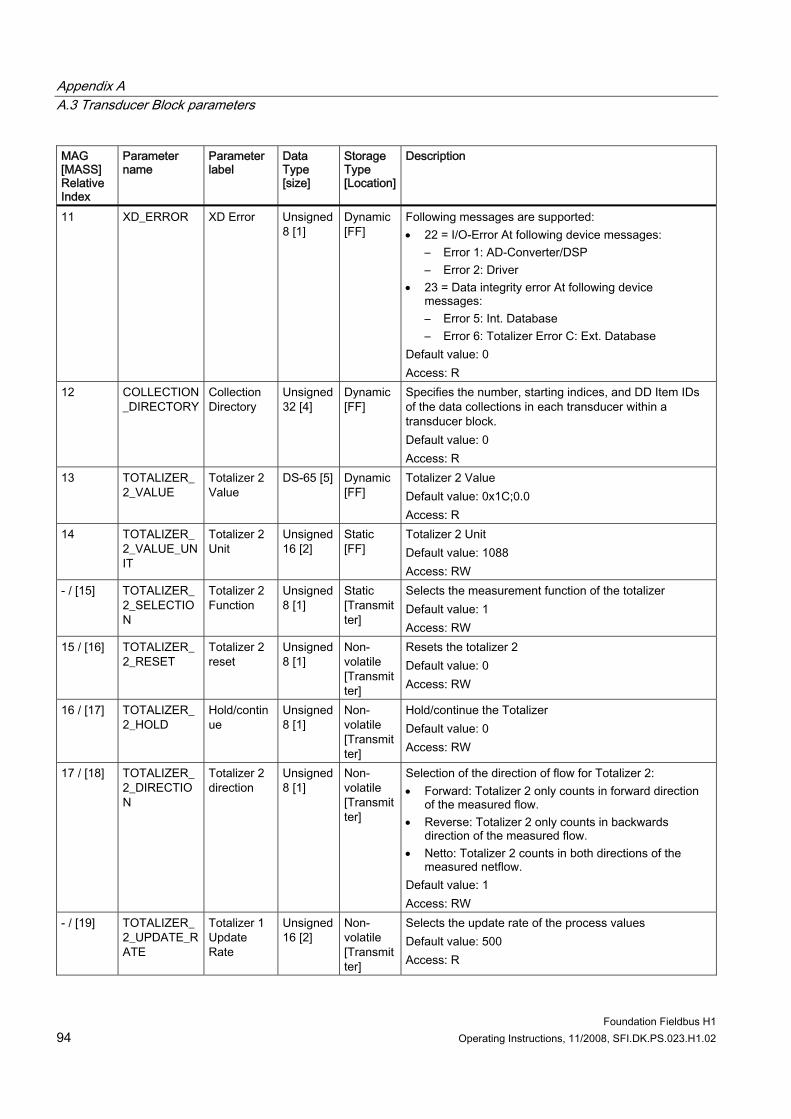
Appendix A A.3 Transducer Block parameters
Foundation Fieldbus H1 94 Operating Instructions, 11/2008, SFI.DK.PS.023.H1.02
MAG [MASS] Relative Index
Parameter name
Parameter label
Data Type [size]
Storage Type [Location]
Description
11 XD_ERROR XD Error Unsigned 8 [1]
Dynamic [FF]
Following messages are supported: • 22 = I/O-Error At following device messages:
– Error 1: AD-Converter/DSP – Error 2: Driver
• 23 = Data integrity error At following device messages: – Error 5: Int. Database – Error 6: Totalizer Error C: Ext. Database
Default value: 0 Access: R
12 COLLECTION_DIRECTORY
Collection Directory
Unsigned 32 [4]
Dynamic [FF]
Specifies the number, starting indices, and DD Item IDs of the data collections in each transducer within a transducer block. Default value: 0 Access: R
13 TOTALIZER_2_VALUE
Totalizer 2 Value
DS-65 [5] Dynamic [FF]
Totalizer 2 Value Default value: 0x1C;0.0 Access: R
14 TOTALIZER_2_VALUE_UNIT
Totalizer 2 Unit
Unsigned 16 [2]
Static [FF]
Totalizer 2 Unit Default value: 1088 Access: RW
- / [15] TOTALIZER_2_SELECTION
Totalizer 2 Function
Unsigned 8 [1]
Static [Transmitter]
Selects the measurement function of the totalizer Default value: 1 Access: RW
15 / [16] TOTALIZER_2_RESET
Totalizer 2 reset
Unsigned 8 [1]
Non-volatile [Transmitter]
Resets the totalizer 2 Default value: 0 Access: RW
16 / [17] TOTALIZER_2_HOLD
Hold/continue
Unsigned 8 [1]
Non-volatile [Transmitter]
Hold/continue the Totalizer Default value: 0 Access: RW
17 / [18] TOTALIZER_2_DIRECTION
Totalizer 2 direction
Unsigned 8 [1]
Non-volatile [Transmitter]
Selection of the direction of flow for Totalizer 2: • Forward: Totalizer 2 only counts in forward direction
of the measured flow. • Reverse: Totalizer 2 only counts in backwards
direction of the measured flow. • Netto: Totalizer 2 counts in both directions of the
measured netflow. Default value: 1 Access: RW
- / [19] TOTALIZER_2_UPDATE_RATE
Totalizer 1 Update Rate
Unsigned 16 [2]
Non-volatile [Transmitter]
Selects the update rate of the process values Default value: 500 Access: R
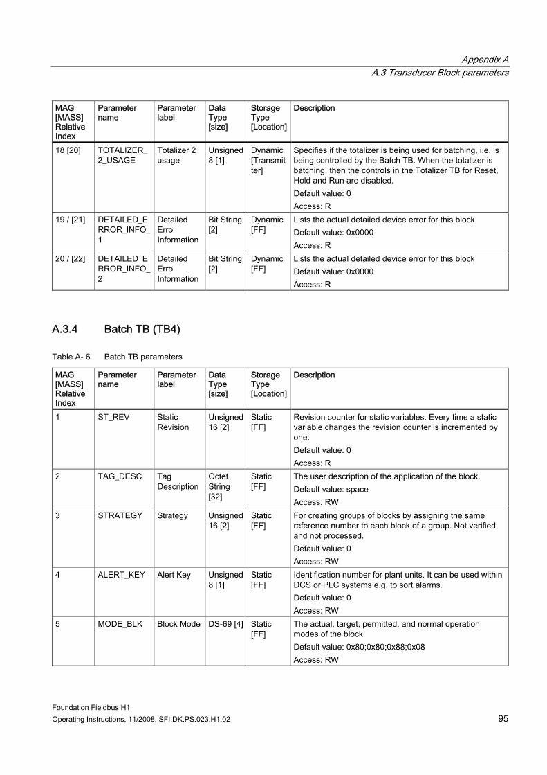
Appendix A A.3 Transducer Block parameters
Foundation Fieldbus H1 Operating Instructions, 11/2008, SFI.DK.PS.023.H1.02 95
MAG [MASS] Relative Index
Parameter name
Parameter label
Data Type [size]
Storage Type [Location]
Description
18 [20] TOTALIZER_2_USAGE
Totalizer 2 usage
Unsigned 8 [1]
Dynamic [Transmitter]
Specifies if the totalizer is being used for batching, i.e. is being controlled by the Batch TB. When the totalizer is batching, then the controls in the Totalizer TB for Reset, Hold and Run are disabled. Default value: 0 Access: R
19 / [21] DETAILED_ERROR_INFO_1
Detailed Erro Information
Bit String [2]
Dynamic [FF]
Lists the actual detailed device error for this block Default value: 0x0000 Access: R
20 / [22] DETAILED_ERROR_INFO_2
Detailed Erro Information
Bit String [2]
Dynamic [FF]
Lists the actual detailed device error for this block Default value: 0x0000 Access: R
A.3.4 Batch TB (TB4)
Table A- 6 Batch TB parameters
MAG [MASS] Relative Index
Parameter name
Parameter label
Data Type [size]
Storage Type [Location]
Description
1 ST_REV Static Revision
Unsigned 16 [2]
Static [FF]
Revision counter for static variables. Every time a static variable changes the revision counter is incremented by one. Default value: 0 Access: R
2 TAG_DESC Tag Description
Octet String [32]
Static [FF]
The user description of the application of the block. Default value: space Access: RW
3 STRATEGY Strategy Unsigned 16 [2]
Static [FF]
For creating groups of blocks by assigning the same reference number to each block of a group. Not verified and not processed. Default value: 0 Access: RW
4 ALERT_KEY Alert Key Unsigned 8 [1]
Static [FF]
Identification number for plant units. It can be used within DCS or PLC systems e.g. to sort alarms. Default value: 0 Access: RW
5 MODE_BLK Block Mode DS-69 [4] Static [FF]
The actual, target, permitted, and normal operation modes of the block. Default value: 0x80;0x80;0x88;0x08 Access: RW
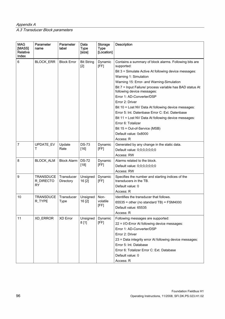
Appendix A A.3 Transducer Block parameters
Foundation Fieldbus H1 96 Operating Instructions, 11/2008, SFI.DK.PS.023.H1.02
MAG [MASS] Relative Index
Parameter name
Parameter label
Data Type [size]
Storage Type [Location]
Description
6 BLOCK_ERR Block Error Bit String [2]
Dynamic [FF]
Contains a summary of block alarms. Following bits are supported: Bit 3 = Simulate Active At following device messages: Warning 1: Simulation Warning 15: Error- and Warning-Simulation Bit 7 = Input Failure/ process variable has BAD status At following device messages: Error 1: AD-Converter/DSP Error 2: Driver Bit 10 = Lost NV Data At following device messages: Error 5: Int. Datenbase Error C: Ext. Datenbase Bit 11 = Lost NV Data At following device messages: Error 6: Totalizer Bit 15 = Out-of-Service (MSB) Default value: 0x8000 Access: R
7 UPDATE_EVT
Update Rate
DS-73 [16]
Dynamic [FF]
Generated by any change in the static data. Default value: 0;0;0,0;0;0;0 Access: RW
8 BLOCK_ALM Block Alarm DS-72 [18]
Dynamic [FF]
Alarms related to the block. Default value: 0;0;0,0;0;0;0 Access: RW
9 TRANSDUCER_DIRECTORY
Transducer Directory
Unsigned 16 [2]
Dynamic [FF]
Specifies the number and starting indices of the transducers in the TB. Default value: 0 Access: R
10 TRANSDUCER_TYPE
Transducer Type
Unsigned 16 [2]
Non-volatile [FF]
Identifies the transducer that follows. 65535 = other (no standard TB) = FSM4000 Default value: 65535 Access: R
11 XD_ERROR XD Error Unsigned 8 [1]
Dynamic [FF]
Following messages are supported: 22 = I/O-Error At following device messages: Error 1: AD-Converter/DSP Error 2: Driver 23 = Data integrity error At following device messages: Error 5: Int. Database Error 6: Totalizer Error C: Ext. Database Default value: 0 Access: R
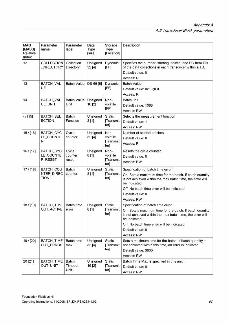
Appendix A A.3 Transducer Block parameters
Foundation Fieldbus H1 Operating Instructions, 11/2008, SFI.DK.PS.023.H1.02 97
MAG [MASS] Relative Index
Parameter name
Parameter label
Data Type [size]
Storage Type [Location]
Description
12 COLLECTION_DIRECTORY
Collection Directory
Unsigned 32 [4]
Dynamic [FF]
Specifies the number, starting indices, and DD Item IDs of the data collections in each transducer within a TB. Default value: 0 Access: R
13 BATCH_VALUE
Batch Value DS-65 [5] Dynamic [FF]
Batch Value Default value: 0x1C;0.0 Access: R
14 BATCH_VALUE_UNIT
Batch Value Unit
Unsigned 16 [2]
Non-volatile [FF]
Batch unit Default value: 1088 Access: RW
- / [15] BATCH_SELECTION
Batch Function
Unsigned 8 [1]
Static [Transmitter]
Selects the measurement function Default value: 1 Access: RW
15 / [16] BATCH_CYCLE_COUNTER
Cycle counter
Unsigned 32 [4]
Non-volatile [Transmitter]
Number of started batches Default value: 0 Access: R
16 / [17] BATCH_CYCLE_COUNTER_RESET
Cycle counter reset
Unsigned 8 [1]
Non-volatile [Transmitter]
Resets the cycle counter. Default value: 0 Access: RW
17 / [18] BATCH_COUNTER_DIRECTION
Batch counter
Unsigned 8 [1]
Static [Transmitter]
Specification of batch time error: On: Sets a maximum time for the batch. If batch quantity is not achieved within the max batch time, the error will be indicated. Off: No batch time error will be indicated. Default value: 0 Access: RW
18 / [19] BATCH_TIMEOUT_ACTIVE
Batch time error
Unsigned 8 [1]
Static [Transmitter]
Specification of batch time error: On: Sets a maximum time for the batch. If batch quantity is not achieved within the max batch time, the error will be indicated. Off: No batch time error will be indicated. Default value: 0 Access: RW
19 / [20] BATCH_TIMEOUT_ERROR
Batch time max
Unsigned 32 [4]
Static [Transmitter]
Sets a maximum time for the batch. If batch quantity is not achieved within this time, an error is indicated. Default value: 3600 Access: RW
20 [21] BATCH_TIMEOUT_UNIT
Batch Timeout Unit
Unsigned 16 [2]
Static [Transmitter]
Batch Time Max is specified in this unit. Default value: 0 Access: RW
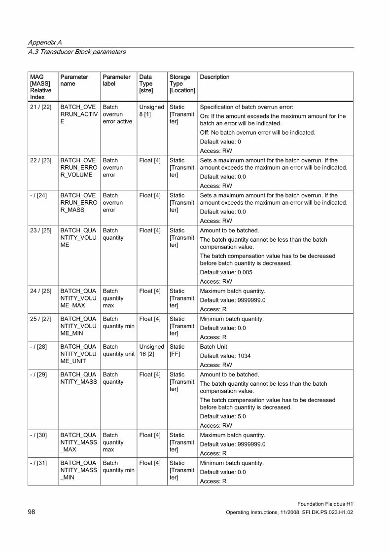
Appendix A A.3 Transducer Block parameters
Foundation Fieldbus H1 98 Operating Instructions, 11/2008, SFI.DK.PS.023.H1.02
MAG [MASS] Relative Index
Parameter name
Parameter label
Data Type [size]
Storage Type [Location]
Description
21 / [22] BATCH_OVERRUN_ACTIVE
Batch overrun error active
Unsigned 8 [1]
Static [Transmitter]
Specification of batch overrun error: On: If the amount exceeds the maximum amount for the batch an error will be indicated. Off: No batch overrun error will be indicated. Default value: 0 Access: RW
22 / [23] BATCH_OVERRUN_ERROR_VOLUME
Batch overrun error
Float [4] Static [Transmitter]
Sets a maximum amount for the batch overrun. If the amount exceeds the maximum an error will be indicated. Default value: 0.0 Access: RW
- / [24] BATCH_OVERRUN_ERROR_MASS
Batch overrun error
Float [4] Static [Transmitter]
Sets a maximum amount for the batch overrun. If the amount exceeds the maximum an error will be indicated. Default value: 0.0 Access: RW
23 / [25] BATCH_QUANTITY_VOLUME
Batch quantity
Float [4] Static [Transmitter]
Amount to be batched. The batch quantity cannot be less than the batch compensation value. The batch compensation value has to be decreased before batch quantity is decreased. Default value: 0.005 Access: RW
24 / [26] BATCH_QUANTITY_VOLUME_MAX
Batch quantity max
Float [4] Static [Transmitter]
Maximum batch quantity. Default value: 9999999.0 Access: R
25 / [27] BATCH_QUANTITY_VOLUME_MIN
Batch quantity min
Float [4] Static [Transmitter]
Minimum batch quantity. Default value: 0.0 Access: R
- / [28] BATCH_QUANTITY_VOLUME_UNIT
Batch quantity unit
Unsigned 16 [2]
Static [FF]
Batch Unit Default value: 1034 Access: RW
- / [29] BATCH_QUANTITY_MASS
Batch quantity
Float [4] Static [Transmitter]
Amount to be batched. The batch quantity cannot be less than the batch compensation value. The batch compensation value has to be decreased before batch quantity is decreased. Default value: 5.0 Access: RW
- / [30] BATCH_QUANTITY_MASS_MAX
Batch quantity max
Float [4] Static [Transmitter]
Maximum batch quantity. Default value: 9999999.0 Access: R
- / [31] BATCH_QUANTITY_MASS_MIN
Batch quantity min
Float [4] Static [Transmitter]
Minimum batch quantity. Default value: 0.0 Access: R
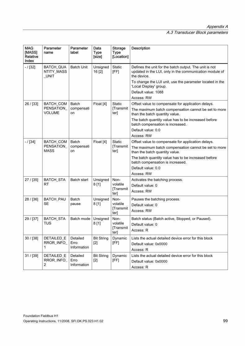
Appendix A A.3 Transducer Block parameters
Foundation Fieldbus H1 Operating Instructions, 11/2008, SFI.DK.PS.023.H1.02 99
MAG [MASS] Relative Index
Parameter name
Parameter label
Data Type [size]
Storage Type [Location]
Description
- / [32] BATCH_QUANTITY_MASS_UNIT
Batch Unit Unsigned 16 [2]
Static [FF]
Defines the unit for the batch output. The unit is not updated in the LUI, only in the communication module of the device. To change the LUI unit, use the parameter located in the 'Local Display' group. Default value: 1088 Access: RW
26 / [33] BATCH_COMPENSATION_VOLUME
Batch compensation
Float [4] Static [Transmitter]
Offset value to compensate for application delays. The maximum batch compensation cannot be set to more than the batch quantity value. The batch quantity value has to be increased before batch compensation is increased. Default value: 0.0 Access: RW
- / [34] BATCH_COMPENSATION_MASS
Batch compensation
Float [4] Static [Transmitter]
Offset value to compensate for application delays. The maximum batch compensation cannot be set to more than the batch quantity value. The batch quantity value has to be increased before batch compensation is increased. Default value: 0.0 Access: RW
27 / [35] BATCH_START
Batch start Unsigned 8 [1]
Non-volatile [Transmitter]
Activates the batching process. Default value: 0 Access: RW
28 / [36] BATCH_PAUSE
Batch pause
Unsigned 8 [1]
Non-volatile [Transmitter]
Pauses the batching process. Default value: 0 Access: RW
29 / [37] BATCH_STATUS
Batch mode Unsigned 8 [1]
Non-volatile [Transmitter]
Batch status (Batch active, Stopped, or Paused). Default value: 0 Access: R
30 / [38] DETAILED_ERROR_INFO_1
Detailed Erro Information
Bit String [2]
Dynamic [FF]
Lists the actual detailed device error for this block Default value: 0x0000 Access: R
31 / [39] DETAILED_ERROR_INFO_2
Detailed Erro Information
Bit String [2]
Dynamic [FF]
Lists the actual detailed device error for this block Default value: 0x0000 Access: R
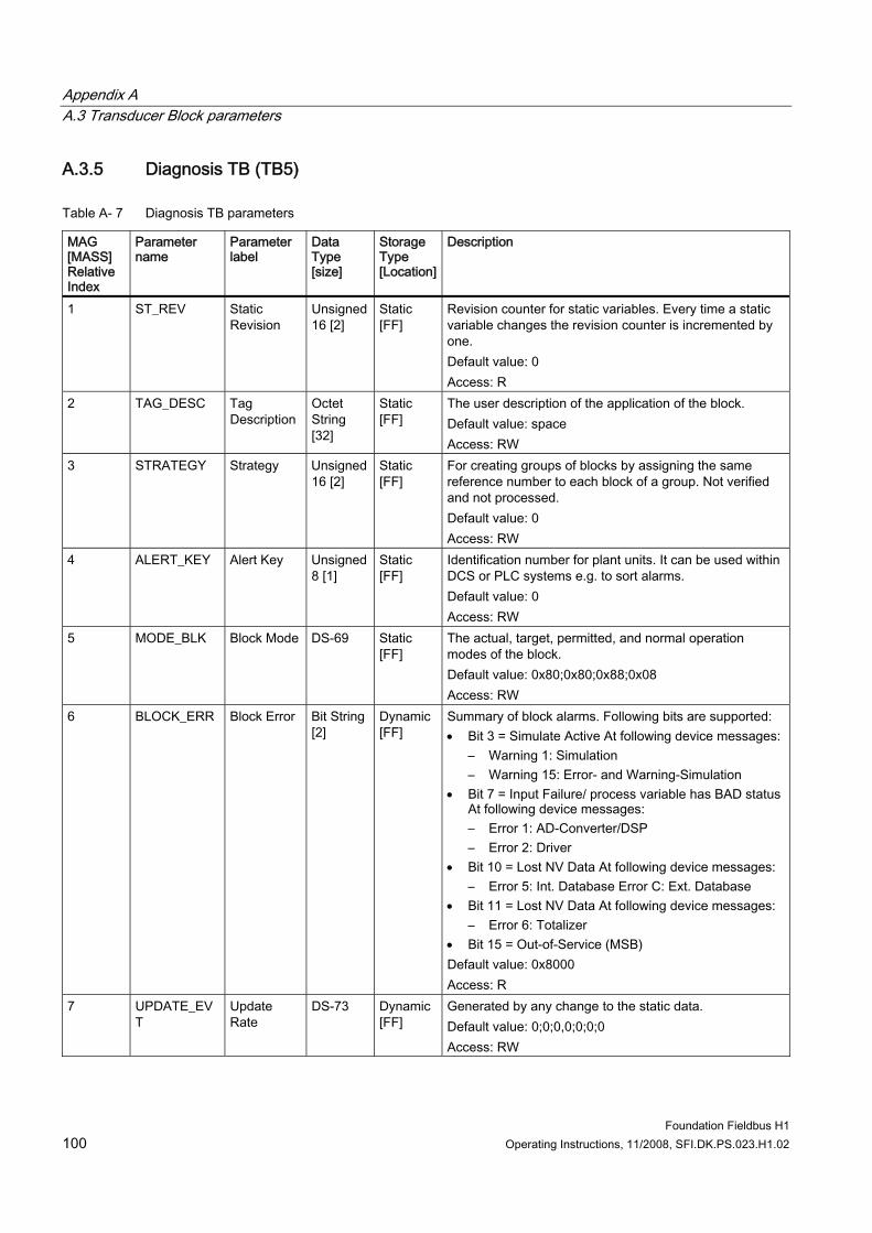
Appendix A A.3 Transducer Block parameters
Foundation Fieldbus H1 100 Operating Instructions, 11/2008, SFI.DK.PS.023.H1.02
A.3.5 Diagnosis TB (TB5)
Table A- 7 Diagnosis TB parameters
MAG [MASS] Relative Index
Parameter name
Parameter label
Data Type [size]
Storage Type [Location]
Description
1 ST_REV Static Revision
Unsigned 16 [2]
Static [FF]
Revision counter for static variables. Every time a static variable changes the revision counter is incremented by one. Default value: 0 Access: R
2 TAG_DESC Tag Description
Octet String [32]
Static [FF]
The user description of the application of the block. Default value: space Access: RW
3 STRATEGY Strategy Unsigned 16 [2]
Static [FF]
For creating groups of blocks by assigning the same reference number to each block of a group. Not verified and not processed. Default value: 0 Access: RW
4 ALERT_KEY Alert Key Unsigned 8 [1]
Static [FF]
Identification number for plant units. It can be used within DCS or PLC systems e.g. to sort alarms. Default value: 0 Access: RW
5 MODE_BLK Block Mode DS-69 Static [FF]
The actual, target, permitted, and normal operation modes of the block. Default value: 0x80;0x80;0x88;0x08 Access: RW
6 BLOCK_ERR Block Error Bit String [2]
Dynamic [FF]
Summary of block alarms. Following bits are supported: • Bit 3 = Simulate Active At following device messages:
– Warning 1: Simulation – Warning 15: Error- and Warning-Simulation
• Bit 7 = Input Failure/ process variable has BAD status At following device messages: – Error 1: AD-Converter/DSP – Error 2: Driver
• Bit 10 = Lost NV Data At following device messages: – Error 5: Int. Database Error C: Ext. Database
• Bit 11 = Lost NV Data At following device messages: – Error 6: Totalizer
• Bit 15 = Out-of-Service (MSB) Default value: 0x8000 Access: R
7 UPDATE_EVT
Update Rate
DS-73 Dynamic [FF]
Generated by any change to the static data. Default value: 0;0;0,0;0;0;0 Access: RW
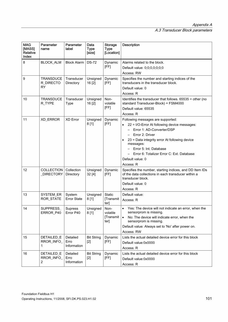
Appendix A A.3 Transducer Block parameters
Foundation Fieldbus H1 Operating Instructions, 11/2008, SFI.DK.PS.023.H1.02 101
MAG [MASS] Relative Index
Parameter name
Parameter label
Data Type [size]
Storage Type [Location]
Description
8 BLOCK_ALM Block Alarm DS-72 Dynamic [FF]
Alarms related to the block. Default value: 0;0;0,0;0;0;0 Access: RW
9 TRANSDUCER_DIRECTORY
Transducer Directory
Unsigned 16 [2]
Dynamic [FF]
Specifies the number and starting indices of the transducers in the transducer block. Default value: 0 Access: R
10 TRANSDUCER_TYPE
Transducer Type
Unsigned 16 [2]
Non-volatile [FF]
Identifies the transducer that follows. 65535 = other (no standard Transducer-Block) = FSM4000 Default value: 65535 Access: R
11 XD_ERROR XD Error Unsigned 8 [1]
Dynamic [FF]
Following messages are supported: • 22 = I/O-Error At following device messages:
– Error 1: AD-Converter/DSP – Error 2: Driver
• 23 = Data integrity error At following device messages: – Error 5: Int. Database – Error 6: Totalizer Error C: Ext. Database
Default value: 0 Access: R
12 COLLECTION_DIRECTORY
Collection Directory
Unsigned 32 [4]
Dynamic [FF]
Specifies the number, starting indices, and DD Item IDs of the data collections in each transducer within a transducer block. Default value: 0 Access: R
13 SYSTEM_ERROR_STATE
System Error State
Unsigned 8 [1]
Static [Transmitter]
Default value: Access: R
14 SUPPRESS_ERROR_P40
Supress Error P40
Unsigned 8 [1]
Non-volatile [Transmitter]
• Yes: The device will not indicate an error, when the sensorprom is missing.
• No: The device will indicate error, when the sensorprom is missing.
Default value: Always set to 'No' after power on. Access: RW
15 DETAILED_ERROR_INFO_1
Detailed Erro Information
Bit String [2]
Dynamic [FF]
Lists the actual detailed device error for this block Default value:0x0000 Access: R
16 DETAILED_ERROR_INFO_2
Detailed Erro Information
Bit String [2]
Dynamic [FF]
Lists the actual detailed device error for this block Default value:0x0000 Access: R
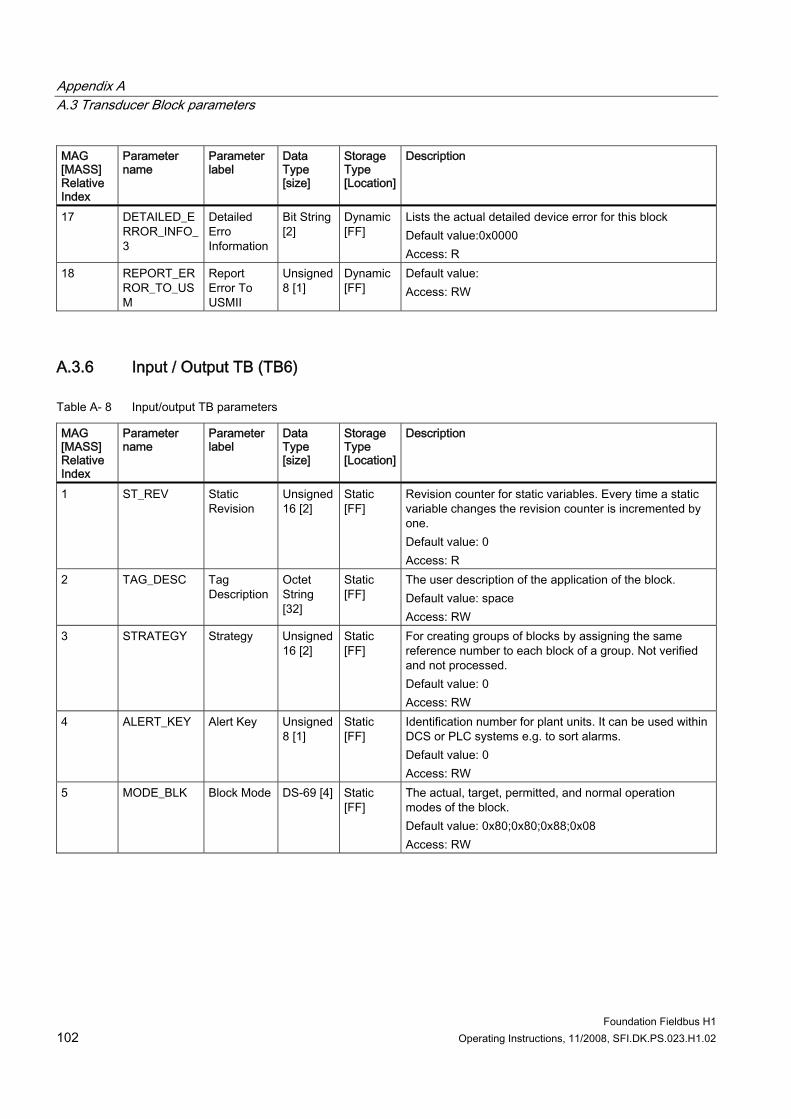
Appendix A A.3 Transducer Block parameters
Foundation Fieldbus H1 102 Operating Instructions, 11/2008, SFI.DK.PS.023.H1.02
MAG [MASS] Relative Index
Parameter name
Parameter label
Data Type [size]
Storage Type [Location]
Description
17 DETAILED_ERROR_INFO_3
Detailed Erro Information
Bit String [2]
Dynamic [FF]
Lists the actual detailed device error for this block Default value:0x0000 Access: R
18 REPORT_ERROR_TO_USM
Report Error To USMII
Unsigned 8 [1]
Dynamic [FF]
Default value: Access: RW
A.3.6 Input / Output TB (TB6)
Table A- 8 Input/output TB parameters
MAG [MASS] Relative Index
Parameter name
Parameter label
Data Type [size]
Storage Type [Location]
Description
1 ST_REV Static Revision
Unsigned 16 [2]
Static [FF]
Revision counter for static variables. Every time a static variable changes the revision counter is incremented by one. Default value: 0 Access: R
2 TAG_DESC Tag Description
Octet String [32]
Static [FF]
The user description of the application of the block. Default value: space Access: RW
3 STRATEGY Strategy Unsigned 16 [2]
Static [FF]
For creating groups of blocks by assigning the same reference number to each block of a group. Not verified and not processed. Default value: 0 Access: RW
4 ALERT_KEY Alert Key Unsigned 8 [1]
Static [FF]
Identification number for plant units. It can be used within DCS or PLC systems e.g. to sort alarms. Default value: 0 Access: RW
5 MODE_BLK Block Mode DS-69 [4] Static [FF]
The actual, target, permitted, and normal operation modes of the block. Default value: 0x80;0x80;0x88;0x08 Access: RW
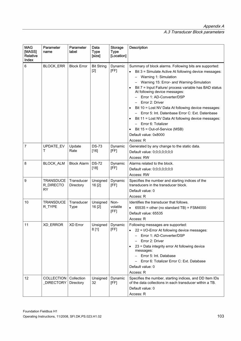
Appendix A A.3 Transducer Block parameters
Foundation Fieldbus H1 Operating Instructions, 11/2008, SFI.DK.PS.023.H1.02 103
MAG [MASS] Relative Index
Parameter name
Parameter label
Data Type [size]
Storage Type [Location]
Description
6 BLOCK_ERR Block Error Bit String [2]
Dynamic [FF]
Summary of block alarms. Following bits are supported: • Bit 3 = Simulate Active At following device messages:
– Warning 1: Simulation – Warning 15: Error- and Warning-Simulation
• Bit 7 = Input Failure/ process variable has BAD status At following device messages: – Error 1: AD-Converter/DSP – Error 2: Driver
• Bit 10 = Lost NV Data At following device messages: – Error 5: Int. Datenbase Error C: Ext. Datenbase
• Bit 11 = Lost NV Data At following device messages: – Error 6: Totalizer
• Bit 15 = Out-of-Service (MSB) Default value: 0x8000 Access: R
7 UPDATE_EVT
Update Rate
DS-73 [16]
Dynamic [FF]
Generated by any change to the static data. Default value: 0;0;0,0;0;0;0 Access: RW
8 BLOCK_ALM Block Alarm DS-72 [18]
Dynamic [FF]
Alarms related to the block. Default value: 0;0;0,0;0;0;0 Access: RW
9 TRANSDUCER_DIRECTORY
Transducer Directory
Unsigned 16 [2]
Dynamic [FF]
Specifies the number and starting indices of the transducers in the transducer block. Default value: 0 Access: R
10 TRANSDUCER_TYPE
Transducer Type
Unsigned 16 [2]
Non-volatile [FF]
Identifies the transducer that follows. • 65535 = other (no standard TB) = FSM4000 Default value: 65535 Access: R
11 XD_ERROR XD Error Unsigned 8 [1]
Dynamic [FF]
Following messages are supported: • 22 = I/O-Error At following device messages:
– Error 1: AD-Converter/DSP – Error 2: Driver
• 23 = Data integrity error At following device messages: – Error 5: Int. Database – Error 6: Totalizer Error C: Ext. Database
Default value: 0 Access: R
12 COLLECTION_DIRECTORY
Collection Directory
Unsigned 32
Dynamic [FF]
Specifies the number, starting indices, and DD Item IDs of the data collections in each transducer within a TB. Default value: 0 Access: R
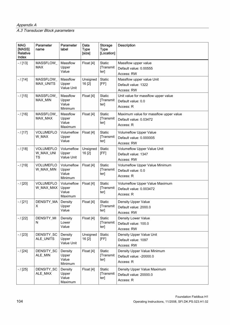
Appendix A A.3 Transducer Block parameters
Foundation Fieldbus H1 104 Operating Instructions, 11/2008, SFI.DK.PS.023.H1.02
MAG [MASS] Relative Index
Parameter name
Parameter label
Data Type [size]
Storage Type [Location]
Description
- / [13] MASSFLOW_MAX
Massflow Upper Value
Float [4] Static [Transmitter]
Massflow upper value Default value: 0.00555 Access: RW
- / [14] MASSFLOW_MAX_UNITS
Massflow Upper Value Unit
Unsigned 16 [2]
Static [FF]
Massflow upper value Unit Default value: 1322 Access: RW
- / [15] MASSFLOW_MAX_MIN
Massflow Upper Value Minimum
Float [4] Static [Transmitter]
Unit value for massflow upper value Default value: 0.0 Access: R
- / [16] MASSFLOW_MAX_MAX
Massflow Upper Value Maximum
Float [4] Static [Transmitter]
Maximum value for massflow upper value Default value: 0.03472 Access: R
- / [17] VOLUMEFLOW_MAX
Volumeflow Upper Value
Float [4] Static [Transmitter]
Volumeflow Upper Value Default value: 0.000005 Access: RW
- / [18] VOLUMEFLOW_MAX_UNITS
Volumeflow Upper Value Unit
Unsigned 16 [2]
Static [FF]
Volumeflow Upper Value Unit Default value: 1347 Access: RW
- / [19] VOLUMEFLOW_MAX_MIN
Volumeflow Upper Value Minimum
Float [4] Static [Transmitter]
Volumeflow Upper Value Minimum Default value: 0.0 Access: R
- / [20] VOLUMEFLOW_MAX_MAX
Volumeflow Upper Value Maximum
Float [4] Static [Transmitter]
Volumeflow Upper Value Maximum Default value: 0.003472 Access: R
- / [21] DENSITY_MAX
Density Upper Value
Float [4] Static [Transmitter]
Density Upper Value Default value: 2000.0 Access: RW
- / [22] DENSITY_MIN
Density Lower Value
Float [4] Static [Transmitter]
Density Lower Value Default value: 100.0 Access: RW
- / [23] DENSITY_SCALE_UNITS
Density Upper Value Unit
Unsigned 16 [2]
Static [FF]
Density Upper Value Unit Default value: 1097 Access: RW
- / [24] DENSITY_SCALE_MIN
Density Upper Value Minimum
Float [4] Static [Transmitter]
Density Upper Value Minimum Default value: -20000.0 Access: R
- / [25] DENSITY_SCALE_MAX
Density Upper Value Maximum
Float [4] Static [Transmitter]
Density Upper Value Maximum Default value: 20000.0 Access: R
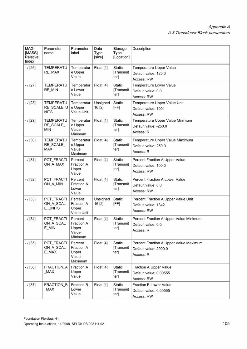
Appendix A A.3 Transducer Block parameters
Foundation Fieldbus H1 Operating Instructions, 11/2008, SFI.DK.PS.023.H1.02 105
MAG [MASS] Relative Index
Parameter name
Parameter label
Data Type [size]
Storage Type [Location]
Description
- / [26] TEMPERATURE_MAX
Temperature Upper Value
Float [4] Static [Transmitter]
Temperature Upper Value Default value: 125.0 Access: RW
- / [27] TEMPERATURE_MIN
Temperature Lower Value
Float [4] Static [Transmitter]
Temperature Lower Value Default value: 0.0 Access: RW
- / [28] TEMPERATURE_SCALE_UNITS
Temperature Upper Value Unit
Unsigned 16 [2]
Static [FF]
Temperature Upper Value Unit Default value: 1001 Access: RW
- / [29] TEMPERATURE_SCALE_MIN
Temperature Upper Value Minimum
Float [4] Static [Transmitter]
Temperature Upper Value Minimum Default value: -250.0 Access: R
- / [30] TEMPERATURE_SCALE_MAX
Temperature Upper Value Maximum
Float [4] Static [Transmitter]
Temperature Upper Value Maximum Default value: 250.0 Access: R
- / [31] PCT_FRACTION_A_MAX
Percent Fraction A Upper Value
Float [4] Static [Transmitter]
Percent Fraction A Upper Value Default value: 100.0 Access: RW
- / [32] PCT_FRACTION_A_MIN
Percent Fraction A Lower Value
Float [4] Static [Transmitter]
Percent Fraction A Lower Value Default value: 0.0 Access: RW
- / [33] PCT_FRACTION_A_SCALE_UNITS
Percent Fraction A Upper Value Unit
Unsigned 16 [2]
Static [FF]
Percent Fraction A Upper Value Unit Default value: 1342 Access: RW
- / [34] PCT_FRACTION_A_SCALE_MIN
Percent Fraction A Upper Value Minimum
Float [4] Static [Transmitter]
Percent Fraction A Upper Value Minimum Default value: 0.0 Access: R
- / [35] PCT_FRACTION_A_SCALE_MAX
Percent Fraction A Upper Value Maximum
Float [4] Static [Transmitter]
Percent Fraction A Upper Value Maximum Default value: 2900.0 Access: R
- / [36] FRACTION_A_MAX
Fraction A Upper Value
Float [4] Static [Transmitter]
Fraction A Upper Value Default value: 0.00555 Access: RW
- / [37] FRACTION_B_MAX
Fraction B Lower Value
Float [4] Static [Transmitter]
Fraction B Lower Value Default value: 0.00555 Access: RW
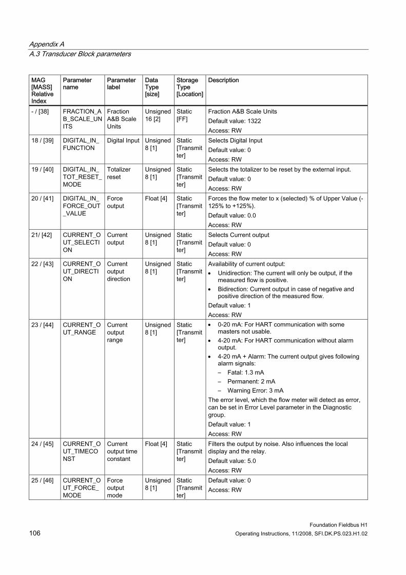
Appendix A A.3 Transducer Block parameters
Foundation Fieldbus H1 106 Operating Instructions, 11/2008, SFI.DK.PS.023.H1.02
MAG [MASS] Relative Index
Parameter name
Parameter label
Data Type [size]
Storage Type [Location]
Description
- / [38] FRACTION_AB_SCALE_UNITS
Fraction A&B Scale Units
Unsigned 16 [2]
Static [FF]
Fraction A&B Scale Units Default value: 1322 Access: RW
18 / [39] DIGITAL_IN_FUNCTION
Digital Input Unsigned 8 [1]
Static [Transmitter]
Selects Digital Input Default value: 0 Access: RW
19 / [40] DIGITAL_IN_TOT_RESET_MODE
Totalizer reset
Unsigned 8 [1]
Static [Transmitter]
Selects the totalizer to be reset by the external input. Default value: 0 Access: RW
20 / [41] DIGITAL_IN_FORCE_OUT_VALUE
Force output
Float [4] Static [Transmitter]
Forces the flow meter to x (selected) % of Upper Value (-125% to +125%). Default value: 0.0 Access: RW
21/ [42] CURRENT_OUT_SELECTION
Current output
Unsigned 8 [1]
Static [Transmitter]
Selects Current output Default value: 0 Access: RW
22 / [43] CURRENT_OUT_DIRECTION
Current output direction
Unsigned 8 [1]
Static [Transmitter]
Availability of current output: • Unidirection: The current will only be output, if the
measured flow is positive. • Bidirection: Current output in case of negative and
positive direction of the measured flow. Default value: 1 Access: RW
23 / [44] CURRENT_OUT_RANGE
Current output range
Unsigned 8 [1]
Static [Transmitter]
• 0-20 mA: For HART communication with some masters not usable.
• 4-20 mA: For HART communication without alarm output.
• 4-20 mA + Alarm: The current output gives following alarm signals: – Fatal: 1.3 mA – Permanent: 2 mA – Warning Error: 3 mA
The error level, which the flow meter will detect as error, can be set in Error Level parameter in the Diagnostic group. Default value: 1 Access: RW
24 / [45] CURRENT_OUT_TIMECONST
Current output time constant
Float [4] Static [Transmitter]
Filters the output by noise. Also influences the local display and the relay. Default value: 5.0 Access: RW
25 / [46] CURRENT_OUT_FORCE_MODE
Force output mode
Unsigned 8 [1]
Static [Transmitter]
Default value: 0 Access: RW
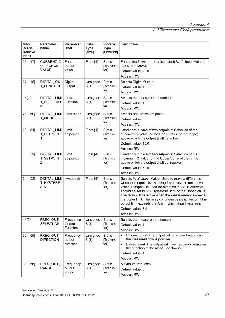
Appendix A A.3 Transducer Block parameters
Foundation Fieldbus H1 Operating Instructions, 11/2008, SFI.DK.PS.023.H1.02 107
MAG [MASS] Relative Index
Parameter name
Parameter label
Data Type [size]
Storage Type [Location]
Description
26 / [47] CURRENT_OUT_FORCE_VALUE
Force output value
Float [4] Static [Transmitter]
Forces the flowmeter to x (selected) % of Upper Value (-125% to +125%). Default value: 20.0 Access: RW
27 / [48] DIGITAL_OUT_FUNCTION
Digital Output
Unsigned 8 [1]
Static [Transmitter]
Selects Digital Output Default value: 1 Access: RW
- / [49] DIGITAL_LIMIT_SELECTION
Limit Function
Unsigned 8 [1]
Static [Transmitter]
Selects the measurement function Default value: 1 Access: RW
28 / [50] DIGITAL_LIMIT_MODE
Limit mode Unsigned 8 [1]
Static [Transmitter]
Selects one or two set points. Default value: 0 Access: RW
29 / [51] DIGITAL_LIMIT_SETPOINT1
Limit setpoint 1
Float [4] Static [Transmitter]
Used only in case of two setpoints: Selection of the minimum % value (of the Upper Value of the range), above which the output shall be active. Default value: 10.0 Access: RW
30 / [52] DIGITAL_LIMIT_SETPOINT2
Limit setpoint 2
Float [4] Static [Transmitter]
Used only in case of two setpoints: Selection of the maximum % value (of the Upper Value of the range), above which the output shall be inactive. Default value: 50.0 Access: RW
31 / [53] DIGITAL_LIMIT_HYSTERESIS
Hysteresis Float [4] Static [Transmitter]
Selects % of Upper Value. Used to make a difference when the setpoint is switching from active to not active. When 1 setpoint is used for direction mode, Hysteresis should be set to 5 %.Hysteresis in % of the Upper Value: The relay will be active when the measurement exceeds the upper limit. The relay continues being active, until the output limit exceeds the Alarm Limit minus hysteresis. Default value: 5.0 Access: RW
- / [54] FREQ_OUT_SELECTION
Frequencu Output Function
Unsigned 8 [1]
Static [Transmitter]
Selects the measurement function Default value: 1 Access: RW
32 / [55] FREQ_OUT_DIRECTION
Frequency output direction
Unsigned 8 [1]
Static [Transmitter]
• Unidirectional: The output will only give frequency if the measured flow is positive.
• Bidirectional: The output will give frequency whatever the direction of the measured flow is.
Default value: 1 Access: RW
33 / [56] FREQ_OUT_RANGE
Frequency output Fmax
Unsigned 8 [1]
Static [Transmitter]
Maximum frequency Default value: 0 Access: RW
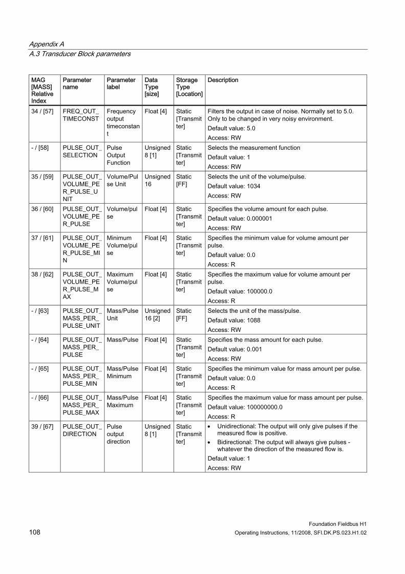
Appendix A A.3 Transducer Block parameters
Foundation Fieldbus H1 108 Operating Instructions, 11/2008, SFI.DK.PS.023.H1.02
MAG [MASS] Relative Index
Parameter name
Parameter label
Data Type [size]
Storage Type [Location]
Description
34 / [57] FREQ_OUT_TIMECONST
Frequency output timeconstant
Float [4] Static [Transmitter]
Filters the output in case of noise. Normally set to 5.0. Only to be changed in very noisy environment. Default value: 5.0 Access: RW
- / [58] PULSE_OUT_SELECTION
Pulse Output Function
Unsigned 8 [1]
Static [Transmitter]
Selects the measurement function Default value: 1 Access: RW
35 / [59] PULSE_OUT_VOLUME_PER_PULSE_UNIT
Volume/Pulse Unit
Unsigned 16
Static [FF]
Selects the unit of the volume/pulse. Default value: 1034 Access: RW
36 / [60] PULSE_OUT_VOLUME_PER_PULSE
Volume/pulse
Float [4] Static [Transmitter]
Specifies the volume amount for each pulse. Default value: 0.000001 Access: RW
37 / [61] PULSE_OUT_VOLUME_PER_PULSE_MIN
Minimum Volume/pulse
Float [4] Static [Transmitter]
Specifies the minimum value for volume amount per pulse. Default value: 0.0 Access: R
38 / [62] PULSE_OUT_VOLUME_PER_PULSE_MAX
Maximum Volume/pulse
Float [4] Static [Transmitter]
Specifies the maximum value for volume amount per pulse. Default value: 100000.0 Access: R
- / [63] PULSE_OUT_MASS_PER_PULSE_UNIT
Mass/Pulse Unit
Unsigned 16 [2]
Static [FF]
Selects the unit of the mass/pulse. Default value: 1088 Access: RW
- / [64] PULSE_OUT_MASS_PER_PULSE
Mass/Pulse Float [4] Static [Transmitter]
Specifies the mass amount for each pulse. Default value: 0.001 Access: RW
- / [65] PULSE_OUT_MASS_PER_PULSE_MIN
Mass/Pulse Minimum
Float [4] Static [Transmitter]
Specifies the minimum value for mass amount per pulse. Default value: 0.0 Access: R
- / [66] PULSE_OUT_MASS_PER_PULSE_MAX
Mass/Pulse Maximum
Float [4] Static [Transmitter]
Specifies the maximum value for mass amount per pulse.Default value: 100000000.0 Access: R
39 / [67] PULSE_OUT_DIRECTION
Pulse output direction
Unsigned 8 [1]
Static [Transmitter]
• Unidirectional: The output will only give pulses if the measured flow is positive.
• Bidirectional: The output will always give pulses - whatever the direction of the measured flow is.
Default value: 1 Access: RW
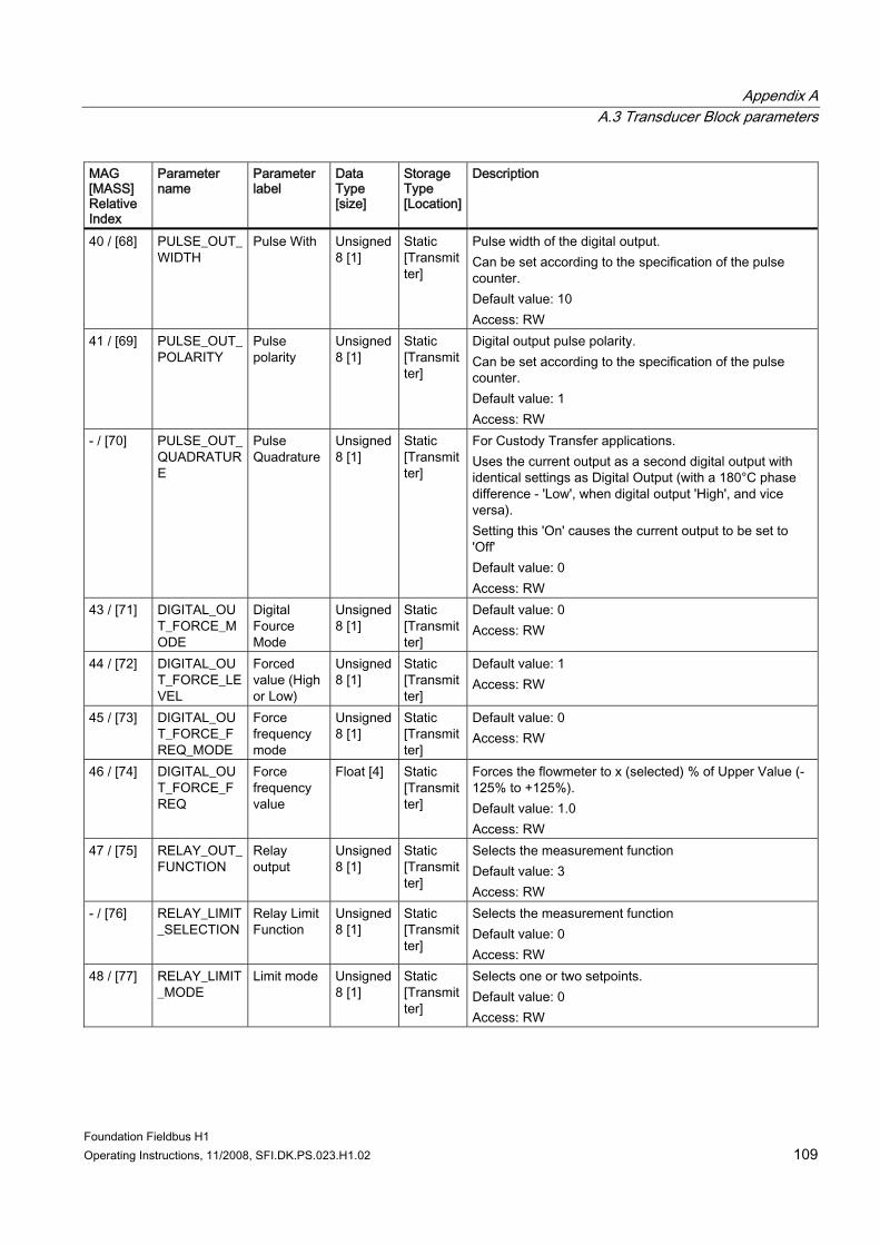
Appendix A A.3 Transducer Block parameters
Foundation Fieldbus H1 Operating Instructions, 11/2008, SFI.DK.PS.023.H1.02 109
MAG [MASS] Relative Index
Parameter name
Parameter label
Data Type [size]
Storage Type [Location]
Description
40 / [68] PULSE_OUT_WIDTH
Pulse With Unsigned 8 [1]
Static [Transmitter]
Pulse width of the digital output. Can be set according to the specification of the pulse counter. Default value: 10 Access: RW
41 / [69] PULSE_OUT_POLARITY
Pulse polarity
Unsigned 8 [1]
Static [Transmitter]
Digital output pulse polarity. Can be set according to the specification of the pulse counter. Default value: 1 Access: RW
- / [70] PULSE_OUT_QUADRATURE
Pulse Quadrature
Unsigned 8 [1]
Static [Transmitter]
For Custody Transfer applications. Uses the current output as a second digital output with identical settings as Digital Output (with a 180°C phase difference - 'Low', when digital output 'High', and vice versa). Setting this 'On' causes the current output to be set to 'Off' Default value: 0 Access: RW
43 / [71] DIGITAL_OUT_FORCE_MODE
Digital Fource Mode
Unsigned 8 [1]
Static [Transmitter]
Default value: 0 Access: RW
44 / [72] DIGITAL_OUT_FORCE_LEVEL
Forced value (High or Low)
Unsigned 8 [1]
Static [Transmitter]
Default value: 1 Access: RW
45 / [73] DIGITAL_OUT_FORCE_FREQ_MODE
Force frequency mode
Unsigned 8 [1]
Static [Transmitter]
Default value: 0 Access: RW
46 / [74] DIGITAL_OUT_FORCE_FREQ
Force frequency value
Float [4] Static [Transmitter]
Forces the flowmeter to x (selected) % of Upper Value (-125% to +125%). Default value: 1.0 Access: RW
47 / [75] RELAY_OUT_FUNCTION
Relay output
Unsigned 8 [1]
Static [Transmitter]
Selects the measurement function Default value: 3 Access: RW
- / [76] RELAY_LIMIT_SELECTION
Relay Limit Function
Unsigned 8 [1]
Static [Transmitter]
Selects the measurement function Default value: 0 Access: RW
48 / [77] RELAY_LIMIT_MODE
Limit mode Unsigned 8 [1]
Static [Transmitter]
Selects one or two setpoints. Default value: 0 Access: RW
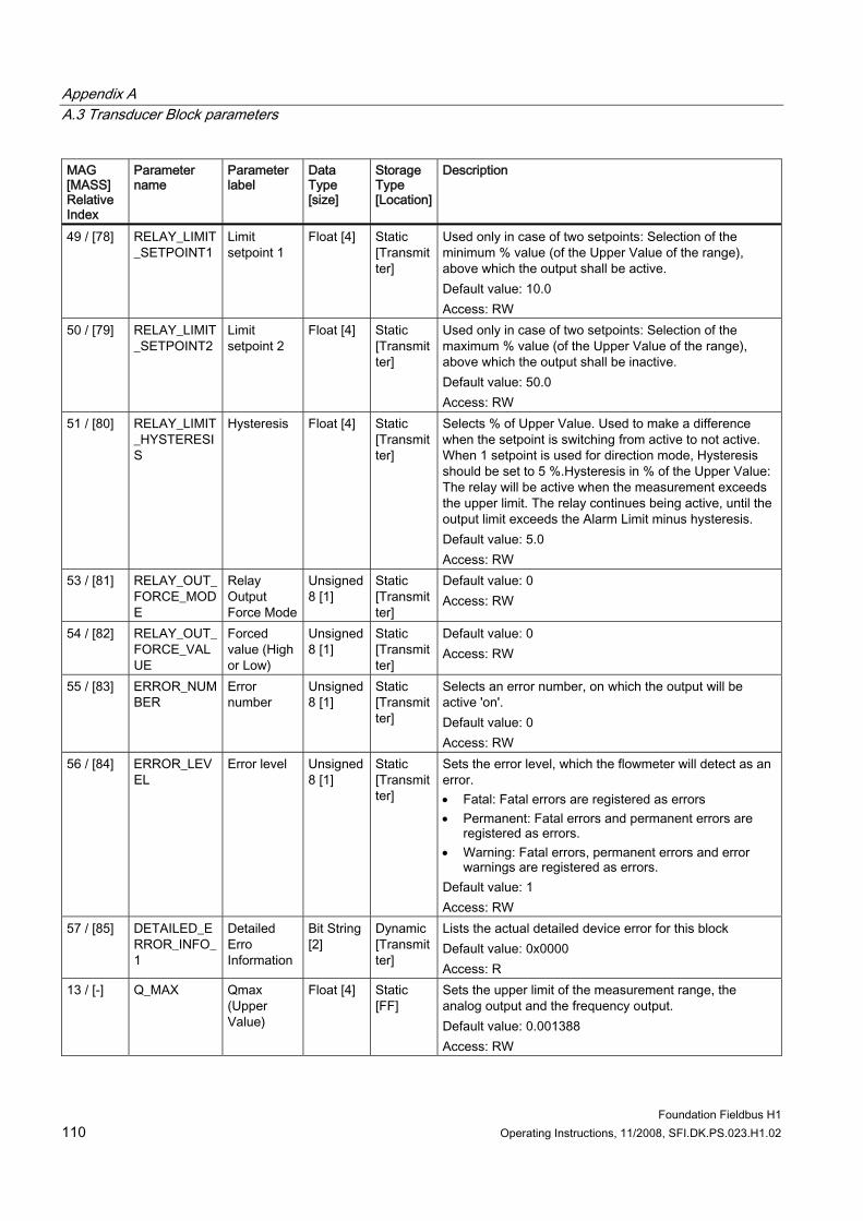
Appendix A A.3 Transducer Block parameters
Foundation Fieldbus H1 110 Operating Instructions, 11/2008, SFI.DK.PS.023.H1.02
MAG [MASS] Relative Index
Parameter name
Parameter label
Data Type [size]
Storage Type [Location]
Description
49 / [78] RELAY_LIMIT_SETPOINT1
Limit setpoint 1
Float [4] Static [Transmitter]
Used only in case of two setpoints: Selection of the minimum % value (of the Upper Value of the range), above which the output shall be active. Default value: 10.0 Access: RW
50 / [79] RELAY_LIMIT_SETPOINT2
Limit setpoint 2
Float [4] Static [Transmitter]
Used only in case of two setpoints: Selection of the maximum % value (of the Upper Value of the range), above which the output shall be inactive. Default value: 50.0 Access: RW
51 / [80] RELAY_LIMIT_HYSTERESIS
Hysteresis Float [4] Static [Transmitter]
Selects % of Upper Value. Used to make a difference when the setpoint is switching from active to not active. When 1 setpoint is used for direction mode, Hysteresis should be set to 5 %.Hysteresis in % of the Upper Value: The relay will be active when the measurement exceeds the upper limit. The relay continues being active, until the output limit exceeds the Alarm Limit minus hysteresis. Default value: 5.0 Access: RW
53 / [81] RELAY_OUT_FORCE_MODE
Relay Output Force Mode
Unsigned 8 [1]
Static [Transmitter]
Default value: 0 Access: RW
54 / [82] RELAY_OUT_FORCE_VALUE
Forced value (High or Low)
Unsigned 8 [1]
Static [Transmitter]
Default value: 0 Access: RW
55 / [83] ERROR_NUMBER
Error number
Unsigned 8 [1]
Static [Transmitter]
Selects an error number, on which the output will be active 'on'. Default value: 0 Access: RW
56 / [84] ERROR_LEVEL
Error level Unsigned 8 [1]
Static [Transmitter]
Sets the error level, which the flowmeter will detect as an error. • Fatal: Fatal errors are registered as errors • Permanent: Fatal errors and permanent errors are
registered as errors. • Warning: Fatal errors, permanent errors and error
warnings are registered as errors. Default value: 1 Access: RW
57 / [85] DETAILED_ERROR_INFO_1
Detailed Erro Information
Bit String [2]
Dynamic [Transmitter]
Lists the actual detailed device error for this block Default value: 0x0000 Access: R
13 / [-] Q_MAX Qmax (Upper Value)
Float [4] Static [FF]
Sets the upper limit of the measurement range, the analog output and the frequency output. Default value: 0.001388 Access: RW
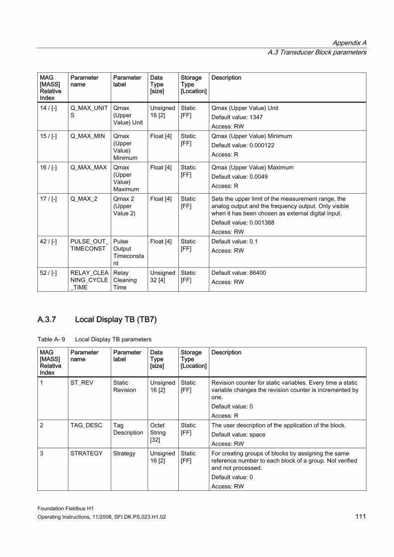
Appendix A A.3 Transducer Block parameters
Foundation Fieldbus H1 Operating Instructions, 11/2008, SFI.DK.PS.023.H1.02 111
MAG [MASS] Relative Index
Parameter name
Parameter label
Data Type [size]
Storage Type [Location]
Description
14 / [-] Q_MAX_UNITS
Qmax (Upper Value) Unit
Unsigned 16 [2]
Static [FF]
Qmax (Upper Value) Unit Default value: 1347 Access: RW
15 / [-] Q_MAX_MIN Qmax (Upper Value) Minimum
Float [4] Static [FF]
Qmax (Upper Value) Minimum Default value: 0.000122 Access: R
16 / [-] Q_MAX_MAX Qmax (Upper Value) Maximum
Float [4] Static [FF]
Qmax (Upper Value) Maximum Default value: 0.0049 Access: R
17 / [-] Q_MAX_2 Qmax 2 (Upper Value 2)
Float [4] Static [FF]
Sets the upper limit of the measurement range, the analog output and the frequency output. Only visible when it has been chosen as external digital input. Default value: 0.001388 Access: RW
42 / [-] PULSE_OUT_TIMECONST
Pulse Output Timeconstant
Float [4] Static [FF]
Default value: 0.1 Access: RW
52 / [-] RELAY_CLEANING_CYCLE_TIME
Relay Cleaning Time
Unsigned 32 [4]
Static [FF]
Default value: 86400 Access: RW
A.3.7 Local Display TB (TB7)
Table A- 9 Local Display TB parameters
MAG [MASS] Relative Index
Parameter name
Parameter label
Data Type [size]
Storage Type [Location]
Description
1 ST_REV Static Revision
Unsigned 16 [2]
Static [FF]
Revision counter for static variables. Every time a static variable changes the revision counter is incremented by one. Default value: 0 Access: R
2 TAG_DESC Tag Description
Octet String [32]
Static [FF]
The user description of the application of the block. Default value: space Access: RW
3 STRATEGY Strategy Unsigned 16 [2]
Static [FF]
For creating groups of blocks by assigning the same reference number to each block of a group. Not verified and not processed. Default value: 0 Access: RW
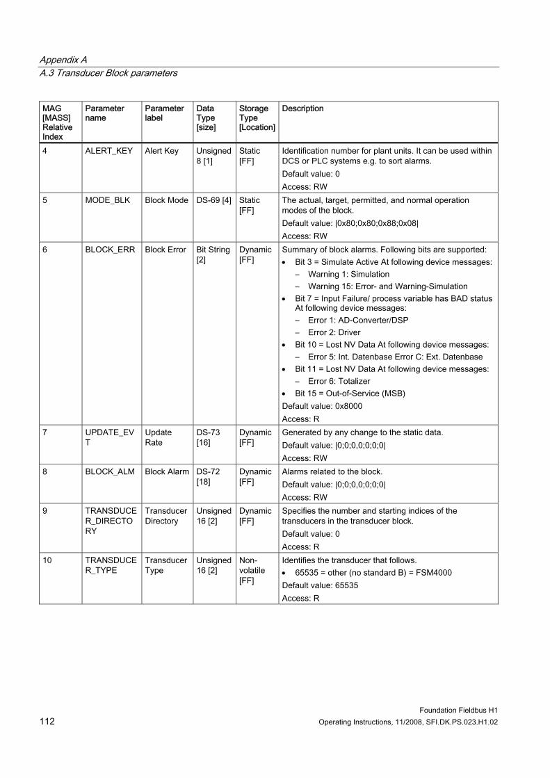
Appendix A A.3 Transducer Block parameters
Foundation Fieldbus H1 112 Operating Instructions, 11/2008, SFI.DK.PS.023.H1.02
MAG [MASS] Relative Index
Parameter name
Parameter label
Data Type [size]
Storage Type [Location]
Description
4 ALERT_KEY Alert Key Unsigned 8 [1]
Static [FF]
Identification number for plant units. It can be used within DCS or PLC systems e.g. to sort alarms. Default value: 0 Access: RW
5 MODE_BLK Block Mode DS-69 [4] Static [FF]
The actual, target, permitted, and normal operation modes of the block. Default value: |0x80;0x80;0x88;0x08| Access: RW
6 BLOCK_ERR Block Error Bit String [2]
Dynamic [FF]
Summary of block alarms. Following bits are supported: • Bit 3 = Simulate Active At following device messages:
– Warning 1: Simulation – Warning 15: Error- and Warning-Simulation
• Bit 7 = Input Failure/ process variable has BAD status At following device messages: – Error 1: AD-Converter/DSP – Error 2: Driver
• Bit 10 = Lost NV Data At following device messages: – Error 5: Int. Datenbase Error C: Ext. Datenbase
• Bit 11 = Lost NV Data At following device messages: – Error 6: Totalizer
• Bit 15 = Out-of-Service (MSB) Default value: 0x8000 Access: R
7 UPDATE_EVT
Update Rate
DS-73 [16]
Dynamic [FF]
Generated by any change to the static data. Default value: |0;0;0,0;0;0;0| Access: RW
8 BLOCK_ALM Block Alarm DS-72 [18]
Dynamic [FF]
Alarms related to the block. Default value: |0;0;0,0;0;0;0| Access: RW
9 TRANSDUCER_DIRECTORY
Transducer Directory
Unsigned 16 [2]
Dynamic [FF]
Specifies the number and starting indices of the transducers in the transducer block. Default value: 0 Access: R
10 TRANSDUCER_TYPE
Transducer Type
Unsigned 16 [2]
Non-volatile [FF]
Identifies the transducer that follows. • 65535 = other (no standard B) = FSM4000 Default value: 65535 Access: R
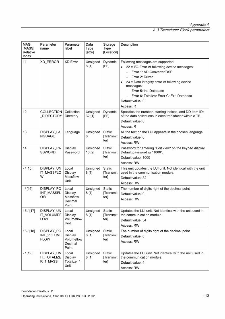
Appendix A A.3 Transducer Block parameters
Foundation Fieldbus H1 Operating Instructions, 11/2008, SFI.DK.PS.023.H1.02 113
MAG [MASS] Relative Index
Parameter name
Parameter label
Data Type [size]
Storage Type [Location]
Description
11 XD_ERROR XD Error Unsigned 8 [1]
Dynamic [FF]
Following messages are supported: • 22 = I/O-Error At following device messages:
– Error 1: AD-Converter/DSP – Error 2: Driver
• 23 = Data integrity error At following device messages: – Error 5: Int. Database – Error 6: Totalizer Error C: Ext. Database
Default value: 0 Access: R
12 COLLECTION_DIRECTORY
Collection Directory
Unsigned 32 [1]
Dynamic [FF]
Specifies the number, starting indices, and DD Item IDs of the data collections in each transducer within a TB. Default value: 0 Access: R
13 DISPLAY_LANGUAGE
Language Unsigned 8
Static [Transmitter]
All the text on the LUI appears in the chosen language. Default value: 0 Access: RW
14 DISPLAY_PASSWORD
Display Password
Unsigned 16 [2]
Static [Transmitter]
Password for entering "Edit view" on the keypad display. Default password iw "1000". Default value: 1000 Access: RW
- / [15] DISPLAY_UNIT_MASSFLOW
Local Display Massflow Unit
Unsigned 8 [1]
Static [Transmitter]
This unit updates the LUI unit. Not identical with the unit used in the communication module. Default value: 32 Access: RW
- / [16] DISPLAY_POINT_MASSFLOW
Local Display Massflow Decimal Point
Unsigned 8 [1]
Static [Transmitter]
The number of digits right of the decimal point Default value: 0 Access: RW
15 / [17] DISPLAY_UNIT_VOLUMEFLOW
Local Display Volumeflow Unit
Unsigned 8 [1]
Static [Transmitter]
Updates the LUI unit. Not identical with the unit used in the communication module. Default value: 34 Access: RW
16 / [18] DISPLAY_POINT_VOLUMEFLOW
Local Display Volumeflow Decimal Point
Unsigned 8 [1]
Static [Transmitter]
The number of digits right of the decimal point Default value: 0 Access: RW
- / [19] DISPLAY_UNIT_TOTALIZER_1_MASS
Local Display Totalizer 1 Unit
Unsigned 8 [1]
Static [Transmitter]
Updates the LUI unit. Not identical with the unit used in the communication module. Default value: 4 Access: RW
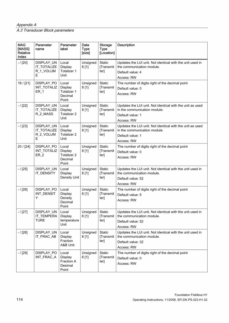
Appendix A A.3 Transducer Block parameters
Foundation Fieldbus H1 114 Operating Instructions, 11/2008, SFI.DK.PS.023.H1.02
MAG [MASS] Relative Index
Parameter name
Parameter label
Data Type [size]
Storage Type [Location]
Description
- / [20] DISPLAY_UNIT_TOTALIZER_1_VOLUME
Local Display Totalizer 1 Unit
Unsigned 8 [1]
Static [Transmitter]
Updates the LUI unit. Not identical with the unit used in the communication module. Default value: 4 Access: RW
18 / [21] DISPLAY_POINT_TOTALIZER_1
Local Display Totalizer 1 Decimal Point
Unsigned 8 [1]
Static [Transmitter]
The number of digits right of the decimal point Default value: 0 Access: RW
- / [22] DISPLAY_UNIT_TOTALIZER_2_MASS
Local Display Totalizer 2 Unit
Unsigned 8 [1]
Static [Transmitter]
Updates the LUI unit. Not identical with the unit as used in the communication module. Default value: 1 Access: RW
- / [23] DISPLAY_UNIT_TOTALIZER_2_VOLUME
Local Display Totalizer 2 Unit
Unsigned 8 [1]
Static [Transmitter]
Updates the LUI unit. Not identical with the unit as used in the communication module. Default value: 1 Access: RW
20 / [24] DISPLAY_POINT_TOTALIZER_2
Local Display Totalizer 2 Decimal Point
Unsigned 8 [1]
Static [Transmitter]
The number of digits right of the decimal point Default value: 0 Access: RW
- / [25] DISPLAY_UNIT_DENSITY
Local Display Density Unit
Unsigned 8 [1]
Static [Transmitter]
Updates the LUI unit. Not identical with the unit used in the communication module. Default value: 52 Access: RW
- / [26] DISPLAY_POINT_DENSITY
Local Display Density Decimal Point
Unsigned 8 [1]
Static [Transmitter]
The number of digits right of the decimal point Default value: 5 Access: RW
- / [27] DISPLAY_UNIT_TEMPERATURE
Local Display temperature Unit
Unsigned 8 [1]
Static [Transmitter]
Updates the LUI unit. Not identical with the unit used in the communication module. Default value: 52 Access: RW
- / [28] DISPLAY_UNIT_FRAC_AB
Local Display Fraction A&B Unit
Unsigned 8 [1]
Static [Transmitter]
Updates the LUI unit. Not identical with the unit used in the communication module. Default value: 32 Access: RW
- / [29] DISPLAY_POINT_FRAC_A
Local Display Fraction A Desimal Point
Unsigned 8 [1]
Static [Transmitter]
The number of digits right of the decimal point Default value: 0 Access: RW
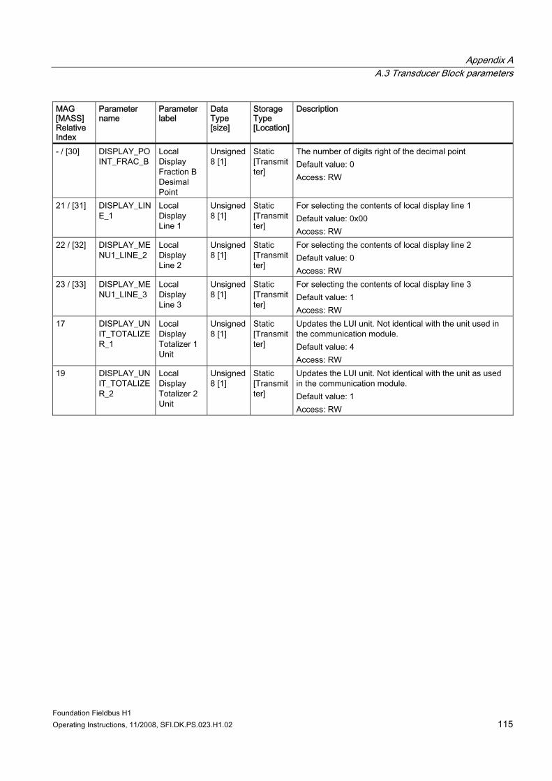
Appendix A A.3 Transducer Block parameters
Foundation Fieldbus H1 Operating Instructions, 11/2008, SFI.DK.PS.023.H1.02 115
MAG [MASS] Relative Index
Parameter name
Parameter label
Data Type [size]
Storage Type [Location]
Description
- / [30] DISPLAY_POINT_FRAC_B
Local Display Fraction B Desimal Point
Unsigned 8 [1]
Static [Transmitter]
The number of digits right of the decimal point Default value: 0 Access: RW
21 / [31] DISPLAY_LINE_1
Local Display Line 1
Unsigned 8 [1]
Static [Transmitter]
For selecting the contents of local display line 1 Default value: 0x00 Access: RW
22 / [32] DISPLAY_MENU1_LINE_2
Local Display Line 2
Unsigned 8 [1]
Static [Transmitter]
For selecting the contents of local display line 2 Default value: 0 Access: RW
23 / [33] DISPLAY_MENU1_LINE_3
Local Display Line 3
Unsigned 8 [1]
Static [Transmitter]
For selecting the contents of local display line 3 Default value: 1 Access: RW
17 DISPLAY_UNIT_TOTALIZER_1
Local Display Totalizer 1 Unit
Unsigned 8 [1]
Static [Transmitter]
Updates the LUI unit. Not identical with the unit used in the communication module. Default value: 4 Access: RW
19 DISPLAY_UNIT_TOTALIZER_2
Local Display Totalizer 2 Unit
Unsigned 8 [1]
Static [Transmitter]
Updates the LUI unit. Not identical with the unit as used in the communication module. Default value: 1 Access: RW

Appendix A A.3 Transducer Block parameters
Foundation Fieldbus H1 116 Operating Instructions, 11/2008, SFI.DK.PS.023.H1.02
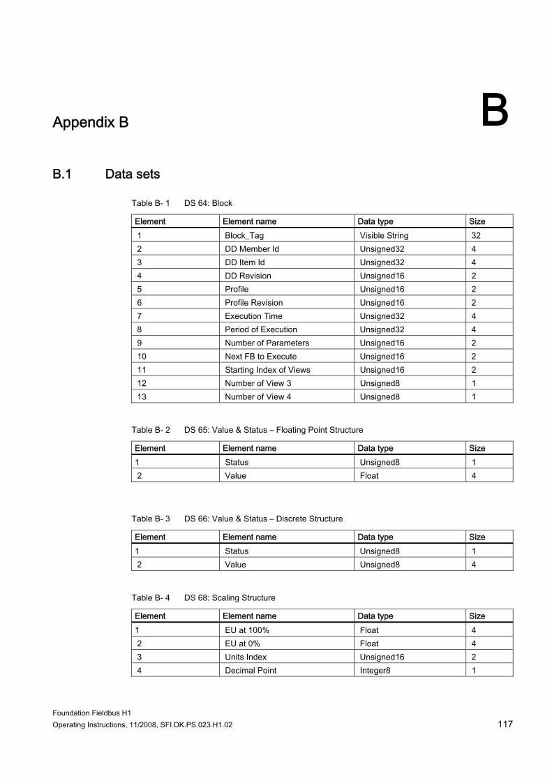
Foundation Fieldbus H1 Operating Instructions, 11/2008, SFI.DK.PS.023.H1.02 117
Appendix B BB.1 Data sets
Table B- 1 DS 64: Block
Element Element name Data type Size 1 Block_Tag Visible String 32 2 DD Member Id Unsigned32 4 3 DD Item Id Unsigned32 4 4 DD Revision Unsigned16 2 5 Profile Unsigned16 2 6 Profile Revision Unsigned16 2 7 Execution Time Unsigned32 4 8 Period of Execution Unsigned32 4 9 Number of Parameters Unsigned16 2 10 Next FB to Execute Unsigned16 2 11 Starting Index of Views Unsigned16 2 12 Number of View 3 Unsigned8 1 13 Number of View 4 Unsigned8 1
Table B- 2 DS 65: Value & Status – Floating Point Structure
Element Element name Data type Size 1 Status Unsigned8 1 2 Value Float 4
Table B- 3 DS 66: Value & Status – Discrete Structure
Element Element name Data type Size 1 Status Unsigned8 1 2 Value Unsigned8 4
Table B- 4 DS 68: Scaling Structure
Element Element name Data type Size 1 EU at 100% Float 4 2 EU at 0% Float 4 3 Units Index Unsigned16 2 4 Decimal Point Integer8 1
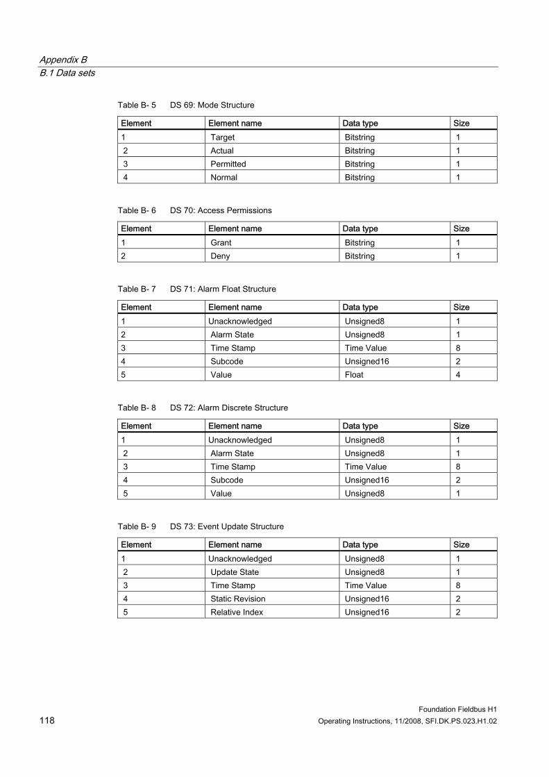
Appendix B B.1 Data sets
Foundation Fieldbus H1 118 Operating Instructions, 11/2008, SFI.DK.PS.023.H1.02
Table B- 5 DS 69: Mode Structure
Element Element name Data type Size 1 Target Bitstring 1 2 Actual Bitstring 1 3 Permitted Bitstring 1 4 Normal Bitstring 1
Table B- 6 DS 70: Access Permissions
Element Element name Data type Size 1 Grant Bitstring 1 2 Deny Bitstring 1
Table B- 7 DS 71: Alarm Float Structure
Element Element name Data type Size 1 Unacknowledged Unsigned8 1 2 Alarm State Unsigned8 1 3 Time Stamp Time Value 8 4 Subcode Unsigned16 2 5 Value Float 4
Table B- 8 DS 72: Alarm Discrete Structure
Element Element name Data type Size 1 Unacknowledged Unsigned8 1 2 Alarm State Unsigned8 1 3 Time Stamp Time Value 8 4 Subcode Unsigned16 2 5 Value Unsigned8 1
Table B- 9 DS 73: Event Update Structure
Element Element name Data type Size 1 Unacknowledged Unsigned8 1 2 Update State Unsigned8 1 3 Time Stamp Time Value 8 4 Static Revision Unsigned16 2 5 Relative Index Unsigned16 2
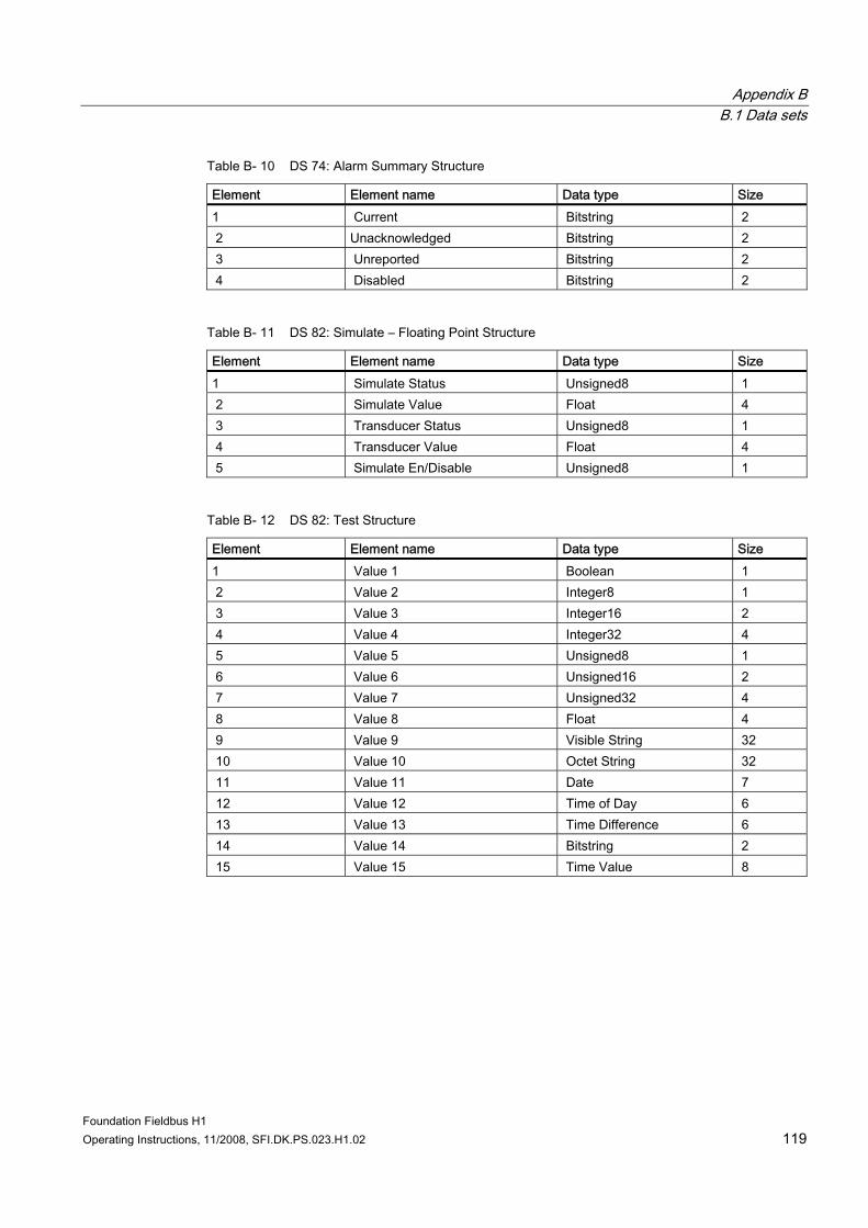
Appendix B B.1 Data sets
Foundation Fieldbus H1 Operating Instructions, 11/2008, SFI.DK.PS.023.H1.02 119
Table B- 10 DS 74: Alarm Summary Structure
Element Element name Data type Size 1 Current Bitstring 2 2 Unacknowledged Bitstring 2 3 Unreported Bitstring 2 4 Disabled Bitstring 2
Table B- 11 DS 82: Simulate – Floating Point Structure
Element Element name Data type Size 1 Simulate Status Unsigned8 1 2 Simulate Value Float 4 3 Transducer Status Unsigned8 1 4 Transducer Value Float 4 5 Simulate En/Disable Unsigned8 1
Table B- 12 DS 82: Test Structure
Element Element name Data type Size 1 Value 1 Boolean 1 2 Value 2 Integer8 1 3 Value 3 Integer16 2 4 Value 4 Integer32 4 5 Value 5 Unsigned8 1 6 Value 6 Unsigned16 2 7 Value 7 Unsigned32 4 8 Value 8 Float 4 9 Value 9 Visible String 32 10 Value 10 Octet String 32 11 Value 11 Date 7 12 Value 12 Time of Day 6 13 Value 13 Time Difference 6 14 Value 14 Bitstring 2 15 Value 15 Time Value 8

Appendix B B.1 Data sets
Foundation Fieldbus H1 120 Operating Instructions, 11/2008, SFI.DK.PS.023.H1.02
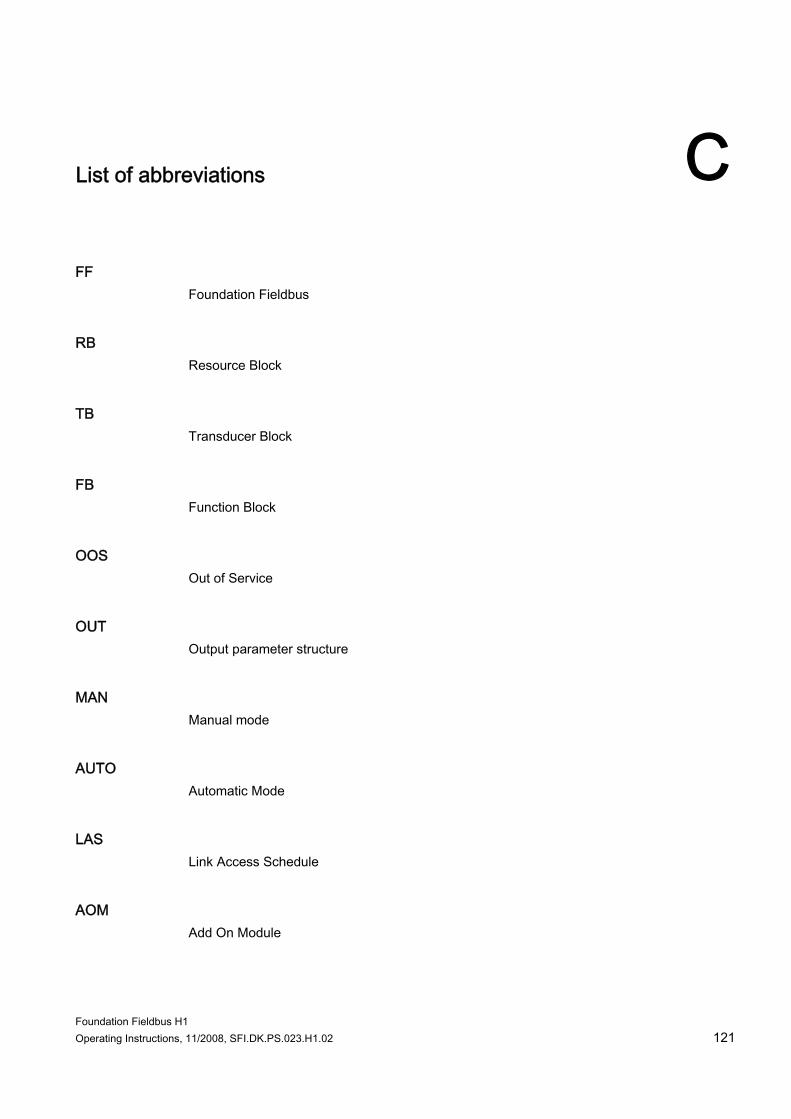
Foundation Fieldbus H1 Operating Instructions, 11/2008, SFI.DK.PS.023.H1.02 121
List of abbreviations C
FF Foundation Fieldbus
RB Resource Block
TB Transducer Block
FB Function Block
OOS Out of Service
OUT Output parameter structure
MAN Manual mode
AUTO Automatic Mode
LAS Link Access Schedule
AOM Add On Module

List of abbreviations
Foundation Fieldbus H1 122 Operating Instructions, 11/2008, SFI.DK.PS.023.H1.02
PID Proportional Integral Derivative
IMAN Initialization Manual Mode
FBAP Function Block Application Process
USM II Universal Signal Module
Foundation Fieldbus H1 Operating Instructions, 11/2008, SFI.DK.PS.023.H1.02 123
Glossary
EMC Performance Electromagnetic Compatibility Performance. The capability of equipment or systems to be used in their intended environment within designed efficiency levels without causing or receiving degradation due to unintentional EMI. EMC generally encompasses all of the electromagnetic disciplines.
Foundation Fieldbus Foundation Fieldbus is an all-digital, serial, two-way communications system that serves as the base-level network in a plant or factory automation environment. Developed and administered by the Fieldbus Foundation.
RB → Resource Block
Resource Block A Resource Block (RB) describes characteristics of the fieldbus device such as the device name, manufacturer and serial number.

Glossary
Foundation Fieldbus H1 124 Operating Instructions, 11/2008, SFI.DK.PS.023.H1.02
Foundation Fieldbus H1 Operating Instructions, 11/2008, SFI.DK.PS.023.H1.02 125
Index
A Alarm, (See Error) Analog Input FB
Configuration, 43 Description, 33 Signal processing, 34
B Batch TB
Description, 30 Diagnostic info, 56 Parameters, 95
Bus termination, (See Electrical Connection)
D Device address, 39 Device Tag, 39 Diagnosis TB
Diagnostic info, 58 Parameters, 100
Discrete Output FB Configuration, 46 Description, 37
Display TB Description, 32
E Electrical connection, 17
Grounding, 18 Electrical Connection
Bus termination, 18 EMC performance, 17 Error
Block alarm, 48 Block errors, 47 Detailed information, 48 Diagnostic overview, 47 Examples, 61 Messages, 63
Ex requirements, 9
F Flow TB
Configuration, 43 Description, 28 Diagnostic info, 51 Parameters, 79
Foundation fieldbus Features, 7 Technology, 7
Function Block Analog Input, (See Analog Input FB) Configuration, 43, 46 Discrete Output, (See Discrete Output FB)
G Grounding, (See Electrical connection)
I Input/output TB
Parameters, 102 Input/Output TB
Diagnostic info, 59 Installation
Hardware, 11 Hazardous area, 9 MAG 6000 19", 12 MAG 6000 I, 14 MAG 6000 IP67, 12 MASS 6000 19", 12 MASS 6000 Ex d, 15 MASS 6000 IP67, 12
L Local Display TB
Parameters, 111
R Resource Block
Configuration, 42 Description, 24
Index
Foundation Fieldbus H1 126 Operating Instructions, 11/2008, SFI.DK.PS.023.H1.02
Diagnostic info, 50
T Totalizer TB
Configuration, 43 Description:Totalizer, (See Totalizer TB) Diagnostic info, 53 Parameters, 90, 92
Transducer Block, 29 Batch, (See Batch TB) Configuration, 43 Description, 25 Diagnosis, (See Diagnosis TB) Display, (See Display TB) Flow, (See Flow TB) Input/Output, (See Input/Output TB) Operating mode, 28 Signal processing, 25
Transmitter settings, 39
W Wiring, (See Electrical connection)


www.siemens.com/processautomation
Siemens A/S Flow InstrumentsNordborgvej 81DK-6430 Nordborg
Subject to change without prior noticeOrder No.: A5E02318728-01Lit. No.: A5E02318728-01 SFIDK.PS.023.H1.02© Siemens AG 11.2008
For more information
www.siemens.com/flow
*A5E02318728*