Embed Size (px)
Citation preview
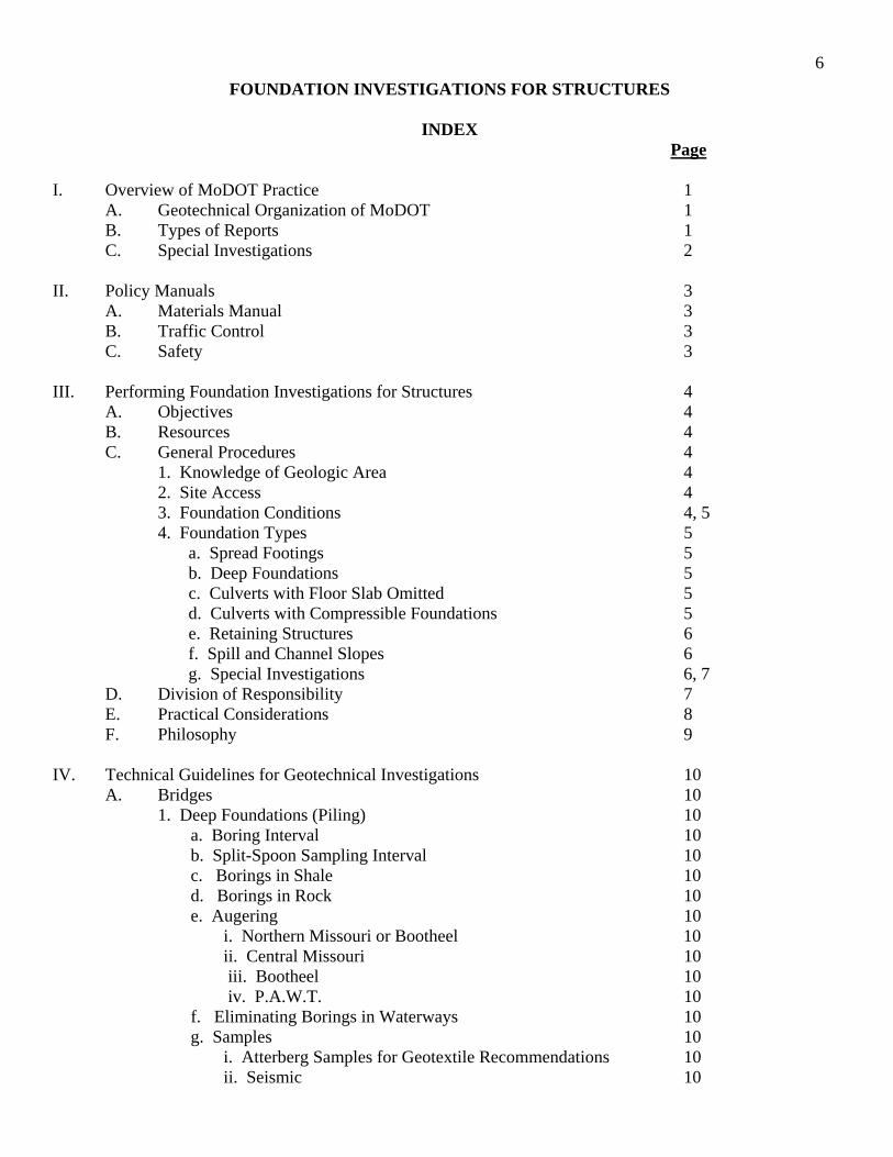
6 FOUNDATION INVESTIGATIONS FOR STRUCTURES
INDEX
Page I. Overview of MoDOT Practice 1 A. Geotechnical Organization of MoDOT 1 B. Types of Reports 1 C. Special Investigations 2 II. Policy Manuals 3 A. Materials Manual 3 B. Traffic Control 3 C. Safety 3 III. Performing Foundation Investigations for Structures 4 A. Objectives 4 B. Resources 4 C. General Procedures 4 1. Knowledge of Geologic Area 4 2. Site Access 4 3. Foundation Conditions 4, 5 4. Foundation Types 5 a. Spread Footings 5 b. Deep Foundations 5 c. Culverts with Floor Slab Omitted 5 d. Culverts with Compressible Foundations 5 e. Retaining Structures 6 f. Spill and Channel Slopes 6 g. Special Investigations 6, 7 D. Division of Responsibility 7 E. Practical Considerations 8 F. Philosophy 9 IV. Technical Guidelines for Geotechnical Investigations 10
A. Bridges 10 1. Deep Foundations (Piling) 10
a. Boring Interval 10 b. Split-Spoon Sampling Interval 10 c. Borings in Shale 10 d. Borings in Rock 10 e. Augering 10 i. Northern Missouri or Bootheel 10 ii. Central Missouri 10 iii. Bootheel 10 iv. P.A.W.T. 10 f. Eliminating Borings in Waterways 10 g. Samples 10 i. Atterberg Samples for Geotextile Recommendations 10 ii. Seismic 10
7
Page
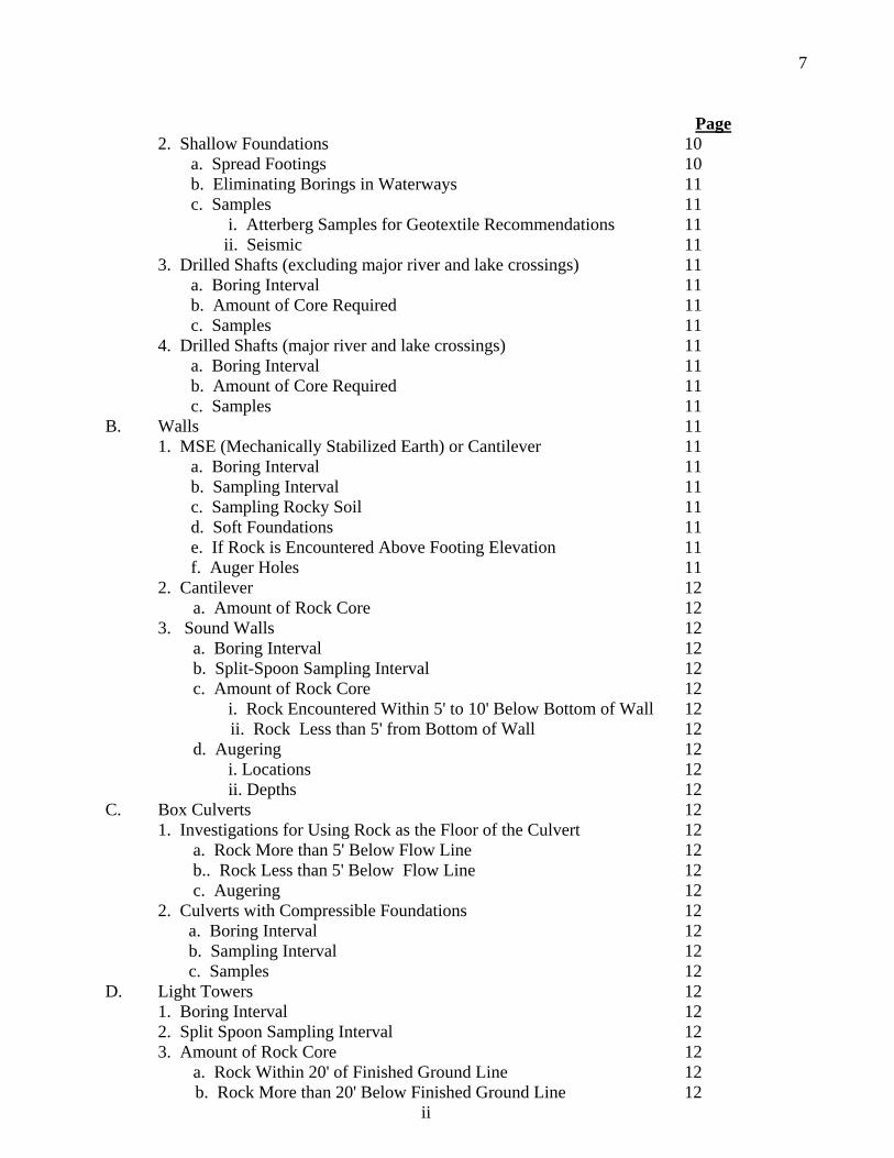
2. Shallow Foundations 10 a. Spread Footings 10 b. Eliminating Borings in Waterways 11 c. Samples 11 i. Atterberg Samples for Geotextile Recommendations 11 ii. Seismic 11 3. Drilled Shafts (excluding major river and lake crossings) 11 a. Boring Interval 11 b. Amount of Core Required 11 c. Samples 11 4. Drilled Shafts (major river and lake crossings) 11 a. Boring Interval 11 b. Amount of Core Required 11 c. Samples 11 B. Walls 11 1. MSE (Mechanically Stabilized Earth) or Cantilever 11 a. Boring Interval 11 b. Sampling Interval 11 c. Sampling Rocky Soil 11 d. Soft Foundations 11 e. If Rock is Encountered Above Footing Elevation 11 f. Auger Holes 11 2. Cantilever 12 a. Amount of Rock Core 12 3. Sound Walls 12 a. Boring Interval 12 b. Split-Spoon Sampling Interval 12 c. Amount of Rock Core 12 i. Rock Encountered Within 5' to 10' Below Bottom of Wall 12 ii. Rock Less than 5' from Bottom of Wall 12 d. Augering 12 i. Locations 12 ii. Depths 12 C. Box Culverts 12 1. Investigations for Using Rock as the Floor of the Culvert 12 a. Rock More than 5' Below Flow Line 12 b.. Rock Less than 5' Below Flow Line 12 c. Augering 12 2. Culverts with Compressible Foundations 12 a. Boring Interval 12 b. Sampling Interval 12 c. Samples 12 D. Light Towers 12 1. Boring Interval 12 2. Split Spoon Sampling Interval 12 3. Amount of Rock Core 12 a. Rock Within 20' of Finished Ground Line 12 b. Rock More than 20' Below Finished Ground Line 12 ii
8
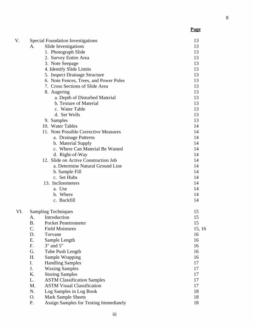
Page V. Special Foundation Investigations 13 A. Slide Investigations 13 1. Photograph Slide 13 2. Survey Entire Area 13 3. Note Seepage 13 4. Identify Slide Limits 13 5. Inspect Drainage Structure 13 6. Note Fences, Trees, and Power Poles 13 7. Cross Sections of Slide Area 13 8. Augering 13 a. Depth of Disturbed Material 13 b. Texture of Material 13 c. Water Table 13 d. Set Wells 13 9. Samples 13 10. Water Tables 14 11. Note Possible Corrective Measures 14 a. Drainage Patterns 14 b. Material Supply 14 c. Where Can Material Be Wasted 14 d. Right-of-Way 14 12. Slide on Active Construction Job 14 a. Determine Natural Ground Line 14 b. Sample Fill 14 c. Set Hubs 14 13. Inclinometers 14 a. Use 14 b. Where 14 c. Backfill 14 VI. Sampling Techniques 15 A. Introduction 15 B. Pocket Penetrometer 15 C. Field Moistures 15, 16 D. Torvane 16 E. Sample Length 16 F. 3" and 5" 16 G. Tube Push Length 16 H. Sample Wrapping 16 I. Handling Samples 17 J. Waxing Samples 17 K. Storing Samples 17 L. ASTM Classification Samples 17 M. ASTM Visual Classification 17 N. Log Samples in Log Book 18 O. Mark Sample Sheets 18 P. Assign Samples for Testing Immediately 18
iii
9
Page
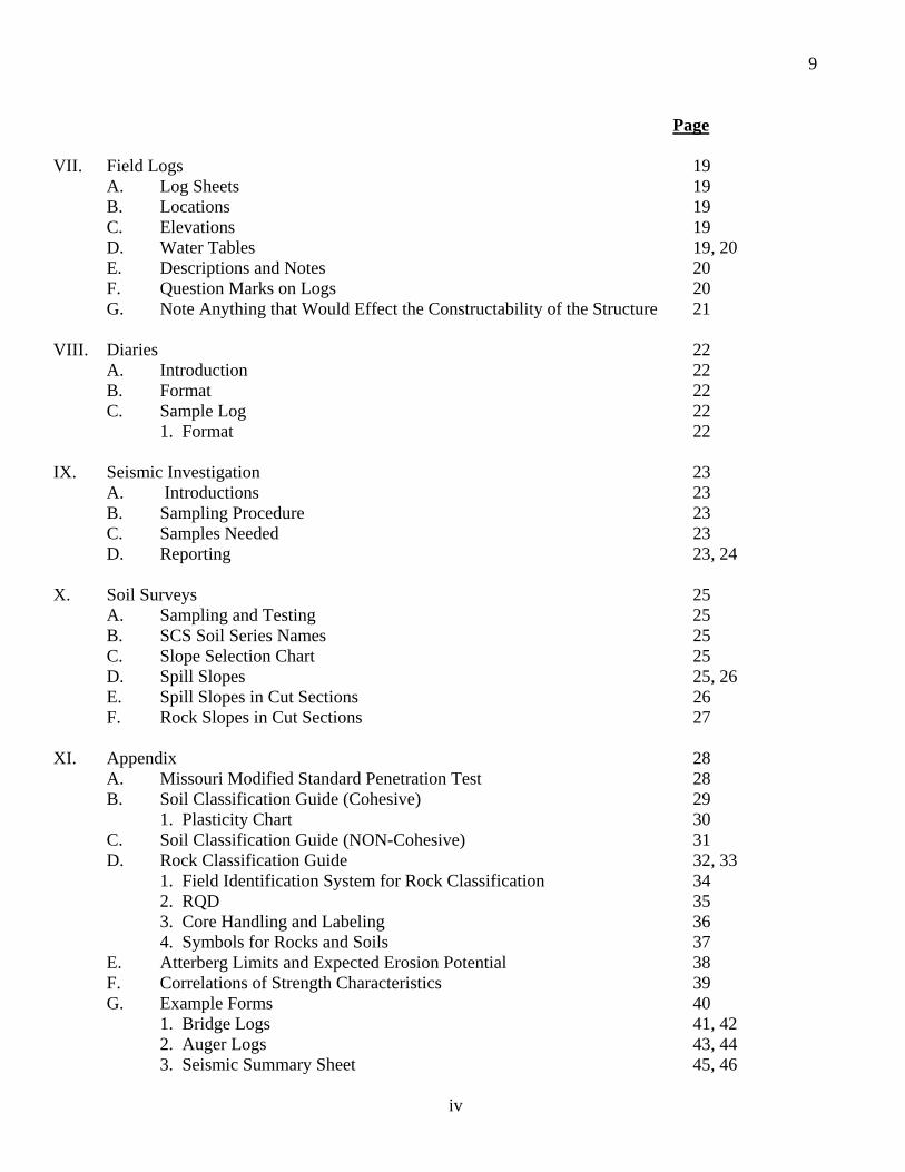
VII. Field Logs 19 A. Log Sheets 19 B. Locations 19 C. Elevations 19 D. Water Tables 19, 20 E. Descriptions and Notes 20 F. Question Marks on Logs 20 G. Note Anything that Would Effect the Constructability of the Structure 21 VIII. Diaries 22 A. Introduction 22 B. Format 22 C. Sample Log 22 1. Format 22 IX. Seismic Investigation 23 A. Introductions 23 B. Sampling Procedure 23 C. Samples Needed 23 D. Reporting 23, 24 X. Soil Surveys 25 A. Sampling and Testing 25 B. SCS Soil Series Names 25 C. Slope Selection Chart 25 D. Spill Slopes 25, 26 E. Spill Slopes in Cut Sections 26 F. Rock Slopes in Cut Sections 27 XI. Appendix 28 A. Missouri Modified Standard Penetration Test 28 B. Soil Classification Guide (Cohesive) 29 1. Plasticity Chart 30 C. Soil Classification Guide (NON-Cohesive) 31 D. Rock Classification Guide 32, 33 1. Field Identification System for Rock Classification 34 2. RQD 35 3. Core Handling and Labeling 36 4. Symbols for Rocks and Soils 37 E. Atterberg Limits and Expected Erosion Potential 38 F. Correlations of Strength Characteristics 39 G. Example Forms 40 1. Bridge Logs 41, 42 2. Auger Logs 43, 44 3. Seismic Summary Sheet 45, 46
iv
1
I. OVERVIEW OF MoDOT PRACTICE A. Geotechnical Organization of MoDOT Geotechnical functions in the Missouri Department of Transportation (MoDOT) are performed by
personnel assigned to the Materials Engineering Unit, both in the district and at the General Headquarters in Jefferson City. Each of the ten districts has a District Geologist or District Soils and Geology Technologist who reports to the District Operations Engineer. At the division/unit level, these functions are administered through the Geotechnical Section.
The district geologist's most important job is the performance and reporting of the soil survey. Basic functions of the soil survey include typing soil and rock materials and determining their limits and engineering characteristics. Other important responsibilities are obtaining preliminary bridge foundation information and identification of potential foundation problems which should be investigated in more detail by division/unit level personnel assigned to the Geotechnical Section. These are referred to as, for lack of a better term, "Special Investigations."
The Geotechnical Section has a specialized soil laboratory with technicians and equipment for performing consolidation tests, various forms of shear tests, and other specialized soil tests. Professional level employees with academic backgrounds in Geology and Civil or Geological Engineering concentrate on one or more specialties. A drilling subsection assigns equipment and personnel statewide as needed by either District or General Headquarters staff. The section does all final foundation investigations for structure layouts prepared by the Bridge Unit's Preliminary Engineering Section and all of the settlement and stability investigations referred to it by the districts. Other duties include slide investigations, work on subgrade and base stabilization, geophysical explorations, research activities, and "other duties as assigned."
The drilling section employs its own staff of field drilling personnel and drilling support equipment.
Drilling equipment includes Mobile B-31 combination power augers and pavement drills, a pavement drill, Failing 1500 core drills, a CME 850 all-terrain unit, CME 45 truck mounted unit for environmental investigations, and track mounted Simco Versa Drills. A portable barge is available to support one of the smaller drills for use on small lakes and streams.
B. Types of Reports 1. The soil survey report touches on foundations by pointing out possible foundation problems.
It also contains basic slope recommendations which affect bridge length, soil types and properties for pavement design, depths to rock and type of rock for determining cut quantities, and cut slope recommendations for soil and rock.
2. The preliminary bridge foundation report, which is submitted by the district as an adjunct to the soil survey report, is usually furnished to the Bridge Unit for their guidance in preparing preliminary bridge layouts and to the Materials Engineering Unit for guidance in conducting a more detailed foundation investigation. (Preliminary borings for such reports may be omitted where access problems are especially difficult.)
3. The final foundation investigation report for structures starts with a formal request from either the Bridge Unit or District following procedures in FS-25 of the Materials Manual. The Bridge Unit or District provides a preliminary layout and a suggested boring plan. This boring plan typically will call for a core and/or standard penetration boring at every other bent with auger borings at the remaining column locations. By prior agreement, it is understood that this suggested boring plan is only a guide which will be modified as deemed necessary. The Geotechnical Section only rarely makes recommendations for specific foundation types. The basic aim is to furnish the Bridge Unit or District with the information needed to develop designs for those foundation types practical for a particular site. Rules of thumb as to what is practical have been developed jointly by the Geotechnical Section and the Bridge Unit. These are discussed elsewhere in this document.
2
C. "Special Investigations" So-called "special investigations" usually pertain to embankment settlement and slope stability
problems. Normally the district identifies potential problems during the soil survey and requests the Geotechnical Section to investigate. In some cases, the problem may not be identified until the final foundation investigation is made for the structure. This is late in the game from a design standpoint, but much better than finding it under contract.
The recommendations made as a result of these investigations may influence structures in various ways; bridge length may be affected, end fill slopes and culvert camber, etc. The most common effect is on construction sequence and rate of construction. Piles should not be driven in an embankment until it has stopped settling and until excess foundation pore pressures have dissipated.
For embankments, i.e., roadway items, very specific recommendations are made as to remedial courses of action rather than saying here is the problem and leaving it to the designer to figure out a solution. However, more than one solution may be technically feasible and it should be realized that other considerations, such as economics, may dictate which solution is actually chosen. Face-to-face meetings with the concerned designers before a report is issued are important to permit mutual exploration of the problem and the ramifications of possible solutions.

3
II. POLICY MANUALS A. Materials Manual [References not included except 1(a)] 1. Field Section 21 - Soil Survey (a) Explanatory Comments on Use of the Slope Selection Chart (included) 2. Field Section 22 - Release of Subsurface Information 3. Field Section 23 - Drilling Operations 4. Field Section 25 - Final Soundings for Structures 5. Field Section 26 - Special Foundation Investigations 6. Field Section 27 - Slide Investigations 7. Field Section 28 - Quarantine Regulations 8. Lab Section 21 - Soil Survey 9. Lab Section 22 - Soils and Geology Laboratory Testing 10. Lab Section 28 - Quarantine Regulations B. Traffic Control (References not included) 1. FHWA - Manual on Uniform Traffic Control Devices 2. Division of Maintenance and Traffic - Traffic Control for Maintenance Operations C. Safety (Reference not included) 1. MHTD - Handbook of Safety Rules and Regulations
4
III. PERFORMING FOUNDATION INVESTIGATIONS FOR STRUCTURES A. Objectives 1. Develop subsurface information adequate to permit design of any technical and economical type of structure foundation for the site under investigation.
2. Develop subsurface information adequate to evaluate stability and deformation potential of embankments and proposed slope templates in the structure area, including walls and channel slopes, if not already addressed by prior investigations.
3. Develop subsurface information adequate to evaluate need for special erosion protection measures necessary to protect the proposed construction. B. Resources 1. Preliminary Bridge Report 2. Soil Survey Report 3. Foundation Investigation Reports for Old or Adjacent Structures 4. As-Built Plans for Old or Adjacent Structures 5. Special Foundation Investigation Reports 6. Geologic and Topographic Maps 7. Air Photos C. General Procedures The first step after receipt of a request from the Bridge Unit or District is a file search for soil
survey reports, preliminary bridge reports, and foundation reports for adjacent structures. A packet of information, which includes plans, correspondence, and prior reports is assembled for field use. Next, the district is consulted for advice as to field conditions, problems with utilities, crops, landowners, etc. If site access conditions are especially bad, someone from the Geotechnical Section may visit the site to determine what equipment may be needed and how the site can be reached. As noted previously, either the Bridge Unit or the District's boring plan may be modified as appropriate given site conditions and constraints. Some of the considerations here include:
1. General knowledge of conditions in the physiographic or geologic area where the work is to be done. This strongly influences the kind of investigation which should be performed and how detailed it should be. For example, in the Springfield area, residual clay over heavily pinnacled rock is likely and the most important thing is to map the rock surface irregularities with a lot of auger borings to rock so that point bearing pile lengths can be determined. In the bootheel area, auger borings are virtually worthless and standard penetration test borings for design of friction piles are most important. 2. Site access conditions are a very practical consideration. It may just not be feasible to drill a hole in the middle of an urban interstate highway and it may be extremely difficult and/or expensive to drill one in the middle of a river. That is where judgments must be made about how necessary that particular boring is -- can conditions be reasonably extrapolated from offset borings, would geophysical methods work as well, etc. In many cases, the borings can be omitted with little risk. In other situations, considerable expense and trouble may be justified to get on location. This may involve a different type of equipment, hiring a bulldozer, mobilizing the portable barge, or temporarily blocking a lane of roadway. The most extreme access problems involve major river or lake crossings where barges, tugs, and support services must be provided by contract. 3. The third consideration involves foundation conditions actually encountered as the investigation progresses. This is a principal reason why all MoDOT foundation investigations are supervised in the field by trained personnel. If conditions encountered are different than anticipated, it is expected that the scope of the investigation will be adjusted as necessary to fit actual conditions.
5
4. As previously noted, the Geotechnical Section rarely makes recommendations for specific foundation types. The basic aim is to furnish the Bridge Unit with the information needed to develop designs for foundation types practical for a particular site. Several rules of thumb are helpful in deciding what is practical. For example:
a. Spread footings Spread footings for bridges will not be considered unless foundation material has an unconfined compressive strength of 3 tsf or more, and such material is within a fairly shallow depth. If firm material is 10 feet or more below final grade line, then piles will be used.
b. Deep Foundations MoDOT guidelines used to estimate how far to carry standard penetration tests for design of friction piles are 30 continuous feet of bearing strata with an N60 value of 20 or greater. It is normal practice to drill half again as deep, or at least 100 feet in any case, to check depth to rock for a point-bearing option. Point bearing is usually a feasible option almost everywhere in the state except in the southeast lowlands or "bootheel" area where sands extend to depths of several thousand feet. Even here, however, a careful check must be made for the possible presence of soft clay layers within and just below the range of probable friction pile penetration.
c. Culverts with Floor Slab Omitted Large box culverts may be built more economically if a floor slab can be omitted.
The Bridge Unit feels this is generally feasible if rock is within five feet of flowline. So, where rock may be shallow, an attempt is made to drill auger holes every 25 feet or so along each proposed wall. An attempt is made to judge the durability of the rock based on inspection of exposures and cores and knowledge of past performance of particular formations. The rock should have an RQD equal to or greater than 75 and should not be thin bedded. If rock is deeper, only a few auger borings to verify this fact may be sufficient.
d. Culverts with Compressible Foundations Culverts, if built over compressible foundations, may require special investigations
based on undisturbed sampling to determine need for camber to compensate for settlement and to assess the danger of joints opening due to spreading caused by settlement. In some areas of the state where this is a particular problem, structural collars are sometimes recommended around joints to control spreading and faulting and piping of silty soils into opened joints.
6
e. Retaining Structures For retaining structures, information is obtained for determination of allowable
footing bearing pressures and angles of internal friction of the materials to be retained and the foundation material. The latter is done by correlation to Plasticity Index (PI) for walls of low height (using the average correlation less one standard deviation), Appendix F, and by drained shear testing for higher and more critical structures. In some cases, it may be necessary to obtain undisturbed samples for testing in order to evaluate overall stability of the slope of which the wall will be a component. By agreement with the Bridge Unit, evaluation of global or overall stability is a Geotechnical Section responsibility. If inadequate global stability is likely, possible solutions are evaluated - such as lowering the base of the wall, increasing the width to height ratio and excavation and replacement with rock fill, etc.
f. Spill and Channel Slopes The Geotechnical Section attempts to furnish overall guidance on prudent slope
selection. This was done first by development of criteria, based on soil type and geologic origin, which is used by the district geologist in making project slope recommendations. Secondly, a review is made, often by specific request of the Bridge Unit, of the adequacy of embankment stability in the vicinity of the bridge ends, particularly at stream crossings. Geotechnical recommendations may affect bridge length, the fill end slopes, and erosion control measures for the channel banks. Often, for example, evidence will be found of channel bank failures which reflect a need for bank stabilization or bridge lengthening.
7
g. Special Investigations These investigations were discussed in Section I where it was noted that, while
normally initiated by the district as part of the soil survey, a problem may not be identified until final bridge soundings are being done. Undisturbed foundation sampling is done or supervised by a geologist, engineer, or senior technician. Large diameter samples are strongly preferred -- often of 5-inch diameter, although 3-inch diameter samples are also commonly taken. In very soft soils, piston samplers are used in lieu of the normal Shelby tubes. Continuous undisturbed sampling is preferred, with frequent use of a 5-inch sampler, then a 3-inch sampler, followed by pushing a split spoon for inspection before cleaning the hole and restarting the cycle. MoDOT practice differs from that of many agencies in that soil samples are routinely extruded in the field. This permits thorough inspection and logging, obtaining field moisture and Atterberg Limits Classification samples, and preliminary field testing with the Torvane and Pocket Penetrometer. Most important, it permits the technical supervisor to develop a good feel for the problem as the investigation progresses. Samples are selected and designated at this time for certain types of testing, wrapped in foil, and sealed in wax in cartons for transport back to the lab. For a typical problem involving an embankment settlement and stability problem, the lab testing program will include moisture contents, Atterberg limits, consolidation tests, unconfined compression, and drained, direct shear tests, all supplemented by Torvane and Pocket Penetrometer tests. Stability analyses are performed using a computer program, either circle analysis (Bishop), block and wedge (Spenser), or both as may be most appropriate for particular circumstances. Total strengths are used to assess the initial or rapid construction case. Effective stress analyses are used to assess fully consolidated conditions as well as intermediate degrees of consolidation. This data can be interpreted to assess the need for controls on rate of construction.
Amount of settlement estimates have been found to be fairly accurate. Actual rates of settlement are usually, but not always faster, than predicted. If a predicted time of settlement appears critical, office calculations are checked by doing field permeability tests and back figuring coefficients of consolidation. Usually, field perms will indicate much faster drainage, but sometimes agree very well with predictions based on laboratory tests. Before using vertical sand drains or any very expensive solution, field permeability testing should be done.
D. Division of Responsibility 1. The Bridge Unit or District prepares a sounding layout with a suggested boring plan. 2. It is the geotech's responsibility to adjust or modify that plan as necessary to accomplish
the objectives previously outlined, based upon the site conditions and practical access problems which may be encountered.
3. The geotech should identify and investigate any geotechnical problems which may preclude or adversely affect the proposed design and be prepared to offer recommendations for alternative designs or design modification.
4. Retaining walls. The Bridge Unit or District is responsible for checking all aspects of structural (internal) stability and for evaluating external stability with respect to overturning, sliding (at the base of the wall) and bearing failure. The Geotechnical Section is responsible for furnishing the data inputs necessary for the external stability checks and for evaluating overall or global stability included slopes for which the proposed wall may be a component.
8
5. Bridges. The Bridge Unit will design the foundation units in almost all cases but may ask
for design assistance in certain instances. It is the geotech's responsibility to furnish data inputs of the type and quantity required to design those foundation types which are technically and economically feasible at each site. This infers that the geotech must have the capability and knowledge, and must have developed the information necessary to design the foundation if requested to do so. Keep in mind that a foundation cannot be designed in isolation. You can design an individual pile or footing but you must also know column and bent loads, group or cluster effects, embankment "drag loads", etc. and understand the interactions of the resulting stresses.
6. Allowable Bearing. "Allowable bearing" is not an intrinsic soil property but rather is a value based upon intrinsic soil properties as influenced by a specific arrangement of specific types, dimensions, and loadings of foundation units and the resulting distributions of stresses. It is not to be confused with "presumptive bearing values" or any specific measure of soil strength. While in most instances the distinction may seem academic, it can be a critical distinction. Examples: (1) A single square footing will have a different "allowable bearing" than a strip footing or a rectangular footing and that of either type may be adversely affected by the proximity of another bearing unit. (2) Similarly, the capacity of a single friction pile or a single earth anchor may be reduced by the proximity of similar units. In any case, "allowable bearing" is influenced not only by the factor of safety against failure (the usual criterion) but also by considerations of allowable deformations in the structure. The underlying reason why higher factors of safety against bearing failure are utilized than for other failure modes is to limit deformation. Keeping unit loads near the unconfined compressive strength (not in excess of about 1.2 Qu) keeps loads at or below the preconsolidation value of the soil.
9
E. Practical Considerations 1. "Proofing" of Foundations. This touches on how foundations are actually built. If point
bearing piles are used, the adequacy of the rock supporting the tip is "proofed" in excess of in-service loads by the dynamic stresses associated with driving the pile so there is relatively little cause for concern about the possibility of a void or cavern beneath the pile tip. This affects the conduct of the foundation investigation. A core may be irrelevant and it may be sufficient to rock bit five feet or so into rock in a couple holes and simply auger to rock (augering deep enough to be sure it's not a boulder) in the rest of the borings - even omitting many holes if rock is deep and of relatively constant elevation. Footings and drilled shafts on the other hand are loaded statically as the bridge is built. "Proofing" must be done by borings, either during the foundation investigation or as a construction requirement after the excavation is completed and prior to placing steel or pouring concrete. Drilled shafts often have very high unit loads so cores and even compression tests of the recovered core may be important, especially with weaker rock types. In hard rock, both cored and rock-bitted holes should be advanced to a significant depth below probable tip elevation to detect possible cavities or soft zones. Of course, if the exact location of the drilled shaft is unknown, only a few deep borings may be sufficient for preliminary design providing the contract is structured to require confirmation borings at each shaft location during construction.
2. Construction Problems. In most cases, investigative techniques are clear cut and the scope of the investigation may be less detailed when only one type of foundation is feasible. However, the scope of investigation should be influenced by considerations of the possible consequences of a change in foundation type during construction. If spread footings on rock are anticipated but no rock is found at one column, then a pile driver must be brought in. If there is no bid item for that type of work, then the price must be negotiated. The contractor will likely ask for an additional working day and claim severe impact costs, etc. For these reasons, more thorough work (at least in numbers of borings) are needed where spread footings are anticipated than for most other foundation types. Of course, being shallow, the borings should be completed more quickly. The reverse circumstance is less critical. If piles are planned and a suitable bearing stratum for footings is found on one bent, it is a simple matter to form and pour the footing while under running the piles at that location. This also has implications with respect to the scope of the foundation investigation. There is often little risk in omitting holes when piles are the logical foundation type and subsurface conditions appear uniform.
3. Footings on Hard Rock. For most simple structures, spread footings on hard rock will be of some practical minimum size such that unit loads will usually be 10 tsf or less and almost never in excess of 20 tsf. This is one reason why strength tests on hard rock are usually rather pointless and judgments on hard rock allowable bearing capacities are subjective, sometimes involving building code tables, RQD, and other empirical means. Keep in mind that the discontinuities of rock (bedding planes, joints, etc.) and, in particular, any loss while coring represent the real bearing limitations of that rock. You must rely on the driller's judgment as to why you didn't recover core. If the drill stem dropped quickly with little or no resistance, you have a void, a clay seam, or other soft material.
Footings on soft rocks such as clay shales, claystones and even some sandstones and siltstones are another matter. Here the normal allowable bearings may be within a much lower range, requiring substantial enlargement of footings. In such cases, fairly detailed test data (SPT, Qu, and even pocket penetrometer data) may be needed to make judgments about allowable footing loads.
10
F. Philosophy Philosophy may seem out of place in a technical guideline. Call it our "organizational culture" if
you want to be more in vogue.
1. THE BORING LOG IS SUPPOSED TO FURNISH USABLE FOUNDATION ENGINEERING INFORMATION. Any geologic, pedologic, or mechanistic factors influencing or contributing to the desired information are of importance. However, it is difficult to visualize what interest a bridge designer might have in a description such as: "A dark gray to black stratum of Willow Pond shale, fissile, containing lingulas, conodonts and various species of brachiopods." Similarly, describing a soil as "dark blue, moist, alluvial Tippecanoe montmorillonitic clay, mottled rusty red, derived from podsolic soil group" is mostly gobbledygook as far as a bridge designer is concerned. Emphasis should be concentrated on such engineering information as will be of value to the designer, regardless of the geotech's interest in micro- or macrofossils, fine distinctions in color shades, etc. For proper perspective, it should be kept in mind that the final aim is to build a bridge.
2. How much information is enough? Answering this question involves a number of considerations. You must keep in mind the logistical overhead in getting you to the job. Property owners and utilities have been cleared; a survey party has staked the job; equipment has been scheduled and travel time committed to and from the job. Obviously you should take time to do it right. The geotech is the one individual on the job with the knowledge and responsibility to ensure the job is complete. It's important that you accept ownership of the investigation as a personal responsibility to satisfy the department's and your own objectives in performing the work.
11
IV. TECHNICAL GUIDELINES FOR GEOTECHNICAL INVESTIGATIONS A. Bridges
1. Deep Foundations (Piling) a. One Penetration hole per two bents. Example 4 bent bridge - 2 penetration holes.
b. Begin at the surface and run penetration tests every 5 feet until 30 continuous feet of 20 blow count or better of bearing strata is encountered. After bearing is achieved, continue penetration tests at 10 foot intervals until rock is encountered or boring is advanced to 100 feet. Core or rock bit 5 feet of rock or shale. (Should adequate bearing be at a deep depth, it may be cheaper to use point bearing piling placed on rock. This is why we need at least 1 boring to establish rock elevation).
c. If shale is encountered and adequate bearing is not achieved in the overburden, run S.P.T. on top of shale, core 5 feet, run S.P.T., core 5 feet and run S.P.T. (This method of shale penetration and core can be modified if the engineer/geologist retrieves an adequate shale sample to run a Qu test. If a good sample of shale is retrieved, eliminate the penetrations at the middle and end of the core runs.)
d. If rock is encountered and adequate bearing is not achieved in the overburden, core10 feet of rock.
e. Augering i. Northern Missouri or Bootheel - Take boring at least to 100 feet if bedrock
is not encountered. Other auger borings should be taken down to the depth where bearing is achieved as determined by the S.P.T. (Should adequate bearing be at a deep depth, it may be cheaper to use point bearing piling placed on rock. This is why we need at least 1 boring to establish rock elevation.)
ii. Central Missouri -- Normally make borings to bedrock and make pattern holes if the top of rock is uneven (more than 5 feet difference in rock elevation within one bent), especially for spread footings.
iii. Bootheel -- Auger some bents at least 20 feet below where bearing was achieved based on S.P.T. Check for any possible soft layers that may exist below bearing strata.
iv. P.A.W.T. - Pushed Auger Without Turning - describes a soft condition and should be noted on any log where this is done.
f. When eliminating bents due to bents falling within the waterway, make sure to penetrate until n values of greater than 20 are found for 25 or 30 consecutive feet below the elevation of the stream bed.
g. Samples i. Atterberg samples of final grade surficial materials are required for
geotextile recommendations on stream crossings. One sample on each side of the stream or river is adequate.
ii. Bridges located in seismic zones require earthquake sampling (see Earthquake Sampling, Page 22). 2. Shallow Foundations
a. Spread footings on some or all of the intermediate bents will normally be used if the top of rock is no more than 12 feet below finished grade. Therefore, at least 10 feet of good core (RQD 75 or higher) should be acquired on the intermediate bents. It is important to make borings on all bents where this condition exists. Piling is normally used on the end bents except where the bridge end is positioned on a rock bluff.
12
b. When eliminating intermediate bents in waterways where rock is within 5 feet of stream bottom elevation, 15 feet of core below stream bottom elevation is needed. On major rivers, borings will normally be based on the type of footings that are planned (drilled shafts or spread footings). Always run S.P.T. in the overburden to aid contractor in driving coffer dams or drilling for shafts.
c. Samples i. Atterberg samples of final grade surficial materials are required for
geotextile recommendations on stream crossings. One sample on each side of the stream or river is adequate.
ii. Bridges located in seismic zones require earthquake sampling (see Earthquake Sampling, Page 22).
3. Drilled Shafts (excluding major river and lake crossings) a. Minimum of one core hole per bent for small structures and for larger structures in
uniform geology. One core hole per column for larger structures in non-uniform geology.
b. Minimum of 25' of core in rock and 30' in shale. i. Ex: For end bearing on rock and a 6' shaft. The top 5' of rock is not
counted. 5' rock socket. For end bearing you need to go 2 X diameter below the rock socket, 12'. 5+5+12=22' say 25'.
c. Need Qu's for design of the rock socket. 4. Drilled Shafts/River Borings ( major river and lake crossings)
a. Minimum of one core hole per column except for drilled shaft groups where 5 core holes per bent will be required.
b. Minimum of 40' of core in rock and 50' in shale. c. Need Qu's for design of the rock socket.
B. Walls 1. MSE (Mechanically Stabilized Earth)
a. Sample about every 200' with shelby tubes. Two sample holes per wall minimum. Try to sample where the wall is the highest.
b. Take undisturbed soil samples to at least 10 feet below footing elevation for Qu, Direct Shear, and Atterberg limits. Need to find internal angle of friction for retained and foundation material. If retained material is fill, get internal angle of friction from soil survey. If sand is encountered, take samples for gradations and atterberg limits as appropriate (seismic).
c. If soil is too rocky to use shelby tube, penetrate every 2 1/2' at least 10 feet below footing elevation. Take Atterberg samples, moisture samples, and pocket penetrometer readings.
d. If foundation material is too soft to use shelby tubes or osterberg sampler, run S.P.T. at 2.5 foot intervals for at least 10 feet below footing elevation. If still soft, go to 5 foot increment. May use cantilever wall on piling. Rock bit or core at least 5 feet of good rock or shale.
e. If rock is encountered above footing elevation or before you sample 10' below bottom of wall, core a minimum of 5 feet below bottom of wall for MSE wall and 10' minimum below bottom of wall for cantilever wall.
f. Auger holes are usually laid out about every 25'. If you are in uniform soil and rock is more than 5 feet below the footing elevation, you can skip every other hole. Auger about 10' below bottom of wall or a little deeper if you suspect rock is close.
13
2. Cantilever Walls or Spread Footings a. Do similar to MSE wall except if rock is near footing elevation and wall may be
set on rock, take 10 feet of core (depending on wall height, 5' of good rock may be adequate) and if shale, run Qu's.
3. Sound Walls a. Use S.P.T. and 3" shelby tubes to sample a hole about every 200 feet of wall
length. b. Push 3" shelby tube 2.5 feet followed by the split spoon sampler. c. Run S.P.T. and shelby tube on the first 5 feet interval below bottom of wall. Take Qus (for determination of allowable bearing), Atterberg samples, moisture
samples, pocket penetrometer readings and torvane readings. d. Continue to run S.P.T. at 2.5 intervals for at least 20 feet below bottom of wall.
Take Atterberg samples, moisture samples, and pocket penetrometer readings. e. Amount of Rock Core. i. If rock is encountered within 5 to 10' below bottom of wall, core 5'.
ii. If rock is less than 5' from bottom of wall, core 10'. f. Augering i. Locations same as MSE walls. ii. Auger 25' below bottom of wall.
C. Box Culverts 1. Investigations for Using Rock as the Floor of the Culvert
a. If rock is encountered deeper than 5' below flow line, drill enough holes to makesure rock does not come up to within 5 feet of flow line.
b. If rock is encountered within 5 feet of the flow line, core a minimum of 2 holes per culvert. Usually one core hole on each side of the road. Core a minimum of 10'.
c. If rock is encountered within 5 feet of the flow line, auger every 10' for each wall in the box culvert (i.e., double box: 3 walls; single box: 2 walls, etc.)
2. Culverts with Compressible Foundations a. Usually one boring on each side of the stream crossing is adequate. The boring
locations should be close to the stream and under the highest part of the proposed fill.
b. Sampling should be continuous shelby tubes unless material is too soft, then the Osterberg sampler should be used.
c. Samples required are 3" for consolidation tests and unconfined compression. Either 3" or 5" for Direct Shear and soil samples for Atterberg test. moistures, pocket penetrometer, and Torvane should also be obtained.
14
D. Light Towers
1. Use S.P.T. and 3" shelby tubes to sample one hole per tower. 2. Push 3" shelby tube 2.5 feet followed by the split spoon. 3. Clean out to the next 5' interval and repeat the procedure.
4. Alternate S.P.T.s and 3" shelby tubes for at least 30' below finished ground line. Take Qus (undrained shear strength), Atterberg samples, moisture samples, pocket penetrometer readings, and torvane readings.
5. In either cohesive or cohesionless soil, perform SPT test at 35’ and 40’ to complete the boring. Take Atterberg samples, moisture samples, and pocket penetrometer readings.
6. If the soil is too rocky to use the Shelby tube, split spoon on 2.5 foot intervals to achieve a depth of 30' below finished ground line and then penetrate again at 35’ and 40’ to complete the boring.
7. Amount of Rock Core. a. If rock is encountered within 20' of finished ground line, core 10'. b. If
rock is more than 20' from finished ground line, core 5'. b. If rock is more than 20' from finished ground line, core 5'.
Tower borings will need to be reported on a bridge log for spt’s and core log and a summary sheet for p-y
parameters and electro-chemical parameters. Cohesionless soil (Sand)
1. Friction Angle from Bowles 1977 using corrected Blow Count (N1)60 (N1)60 = CnN60 (N1)60 = N60 corrected for effective Overburden Pressure Cn = correction factor for Overburden Pressure (Peck et. al.1974)
2. Relative density from either DM 7.1-87 or FHWA/RD-86/102. DM 7.1 probably a better value because it accounts for effective overburden pressure.
Cohesive soils 1. Undrained Shear Strength- USS or C from Bowles 1977 using uncorrected blow count
N60, preferably Qu/2. 2. Friction Angle from correlation of PI to angle of internal friction minus one standard
deviation as published in Navdocks DM-7. P-Y Curve Parameters
1. K(f) = slope (variation) of linear subgrade modulus. From Section 6.1 of the Bridge Manual or “Soil Properties (Lpile & Com624P)”
2. K(f)cyclic = for cyclic loading 3. E50 = strain at 50 % of the maximum difference in principal stresses, unitless, from Qu
test and Section 6.1 of the Bridge Manual or “Soil Properties (Lpile & Com624P)” Electro Chemical Parameters
Resistivity is a function of the chloride ion and sulfate ion content and most of the time we will not run this test. To run the test we need about half a materials sack and the sample is entered into site manager.
15
V. SPECIAL FOUNDATION INVESTIGATIONS
A. Slide Investigations 1. Photograph slide and improvements effected by the movement such as culverts, bridge
ends, utility poles, guard rail, pavement, fences, etc. Also, a good set of field notes should be kept. All written matter should be appropriately dated and identified.
2. Survey entire area, leave no stone unturned (walk out area). 3. Make notations concerning seepage, type of vegetation, etc. Locate seepage on sketches
of plan and profile of slide. 4. Identify slide by station limits. If station numbers are not available, reference slide,
soundings, and other pertinent information to the nearest crossroad drainage structure or bridge end. One of the 4 compass points can be used to describe the offsets. Final plans can then be acquired and station numbers assigned to the various field notes. Field notes should include what the offsets are referenced to such as CL lane, CL median, edge of pavement, baseline, etc.
5. Drainage structures should be inspected to determine if slide is deep seated and if structure replacement is necessary. (Measure distance from end of structure to major cracks or to any open joints.)
6. Note leaning fences, trees, and power poles. Note the direction they lean. Rows of steel fence posts may be placed on the slope or slide area to detect further movements.
7. Besides cross sectioning the slide area, at least one cross section should be taken at each end of the slide on the undisturbed slope. The spacing and number of sections taken in the slide area should be determined by the length and uniformity of slope and slide. Sections should extend out far enough to implement possible repairs.
8. Power auger soundings should supply the following information: a. Depth of disturbed material, especially for shallow slides. (Deep seated slides may
require sampling as well as auger soundings to determine depth of slide.) Enough points should be drilled on the cross section to determine the location of the slide plane with reasonable accuracy. The location of the slide plane may be determined by pushing the auger. The scarp(s) of the slide should be plotted on the cross section as well as the sounding information to determine if a logical slide plane can be drawn. Additional soundings can be made at this time if necessary.
b. The texture, color, and consistency of all materials should be logged. (The term "till" should be used in the log where appropriate along with the texture and consistency.)
c. Water table reading should be taken after the hole has been drilled and again the following day, if possible. (For fill slides, water tables should be established on the shoulder, slide, and toe of slide. For backslope slides, water tables should be established back of the cut and on the slide.) It is suggested that 4 inch holes be drilled to establish water tables. Perforated galvanized down spout can be used to hold holes open.
d. Artesian pressures should be determined where applicable. Well points should be placed in those zones suspected of carrying water. These can be made cheaply by sawing slots in PVC pipe and setting the slotted end section in a sand chamber sealed with bentonite.
9. Undisturbed samples should be taken for the following tests for all slides: a. TV and P.P. b. Direct Shear c. Atterberg Limits d. Moisture
10. Water tables should also be recorded for core drill holes. Make a notation if bentonite is
16
used and record dates and times of readings and the date the hole was drilled. 11. Make notes pertinent to possible corrective measures. Some items to be considered are as
follows: a. Will possible repairs change drainage patterns or should drainage be changed to
protect repaired slide area. Will alterations cause damage to private property. b. Can adequate materials be obtained nearby to repair the slide. (Can suitable soil
be acquired from adjacent backslopes for slope flattening.) c. Where can disturbed material be wasted. d. If additional right-of-way is needed, what type of property will be involved.
12. Procedure for investigating a fill slide on an active construction site may be somewhat different especially if the type of slide (fill failure or foundation failure) cannot be determined by visual observation. a. Sample through fill and determine elevation of natural ground and compare it with
original ground line shown on plans or ground line outside construction limits. b. Sample fill and foundation to determine the preconsolidation pressures as well as
those tests listed under item number 9. (If foundation soil is over consolidated then failure is probably confined to fill.)
c. Set hubs near toe of fill and on the distressed fill and record the offsets and the elevations. (If hubs on fill move independent of hubs at toe of fill, this may indicate fill failure. Should all hubs move, this may indicate foundation failure.)
13. Inclinometers may be installed to determine the depth of the failure surface and rate of slide movement. a. Inclinometers are typically installed on larger slides or on slides that are not of
immediate concern and allow time for monitoring of the slide movement. Inclinometers may also be installed on active construction jobs if potential slope failure is of concern.
b. Inclinometers should be installed in the slide mass and should extend a minimum of 15 feet below the anticipated failure surface.
c. Inclinometers should be installed in a hole backfilled with grout although sand backfill is acceptable. The sand backfill is not as sensitive to movements as the grout.
17
VI. UNDISTURBED SAMPLING TECHNIQUES
A. Introduction Undisturbed Sampling refers to obtaining soil samples using either shelby tubes or the osterberg.
We take continuous samples and all usable samples should be wrapped and transported to the lab. The general procedure for the Failings and CME is to push a 5" shelby followed by a 3" shelby. The hole is then cleaned out and the process is repeated. Under no circumstances should continuous 3" shelby's be used since this leads to sample disturbance. If the soil becomes too rocky to use the shelby tube, disturbed samples may be obtained by using the SPT-Spoon. The Simco Versa Drill can only push 3" shelby tubes. No more than 2 tubes should be pushed before you require the driller to clean out. In swelling or caving soils it may be necessary to clean out after every push. In soft to medium stiff soils, pocket penetrometer 0.5 or less, it will be necessary to use a piston sampler such as the Osterberg sampler.
B. Pocket Penetrometer 1. Firm, SLOW, constant push. 2. Take more than one (1) reading on a sample (average values).
3. The pocket penetrometer is a useful tool but has definite limitations. It was calibrated by the manufacturer against unconfined compression tests made on "silty clays and clayey soils." Correlation of penetrometer values against unconfined tests of Missouri soils show marked disagreement, with penetrometer values almost always exceeding unconfined values (this is believed, to a large extent, to be due to the effect of structure often found in Missouri soils). As the clay content increases, however, the correlation improves. For certain soil types and particularly in certain areas, more definite correlations are possible and may be of value. Obviously, penetrometer values in non-cohesive soils are meaningless and should not be recorded.
4. Pocket penetrations should be made on each cut surface throughout a sample and the range in readings indicated on the sampling log. Averages of several readings on a surface are preferable to just one.
5. Bear in mind that the pocket penetrometer is at best a crude instrument. Dirt about the plunger or the spring may influence readings. Springs get old. Checks indicate that various penetrometers deviate by a quarter ton or more in indicated values under the same load.
6. For Missouri soil the Pc values are generally equal to the pocket penetrometer value in KSF + 1 KSF. Ex. (Pocket Penetrometer reading is 1 tsf, the Pc = 1 tsf + 1 ksf = 3ksf). This can be a guide in setting up consolidation tests. If the calculated P2 value at a certain depth under a proposed fill is, say 2.5 KSF, and the soil at that depth has a pocket penetrometer reading of 3.0 TSF, or 6.0 KSF, then that soil is obviously preconsolidated beyond the anticipated P2 loading and a consolidation test would probably be a waste of money and time. Of course, if in doubt, make the test.
C. Field Moistures
1. Field moisture samples should be taken immediately from undisturbed samples and sealed in tared moisture cans with tape. Excess moistures as is found about the wetted circumference of most samples should be trimmed away and the moisture sample should be taken from the interior of the sample. Moisture samples of saturated granular materials are of very little value as the moisture content will change with densification or loosening during sampling, extruding, and handling, as well as by draining freely in the case of sands. Moisture samples of a borderline material such as silt should be taken carefully to avoid disturbed zones.
18
2. A moisture sample should be taken for each soil type encountered, or for marked changes in consistency within a soil type. Indicate on the sampling log the stratum or depth represented by the moisture can.
3. Volume of sample -- fill container nearly full. 4. Do not allow wax to get on the cans!!! 5. Do not allow them to get dirty!!! 6. Make sure electrical tape is stretched on can to ensure a good seal.
D. Torvane 1. Must be taken on flat surface. 2. Fingers must not interfere with free rotation of measurement dial. 3. SLOW, constant rate of shear. E. Sample Length 1. 5" samples -- Trim to fit fully within carton
2. 3" samples -- Trim to be 6" for good Qu test (Qu sample length should be at least 2 x Diameter) and for Direct Shear and Consolidation tests. If a 6 inch sample is unattainable, bring what you can but note on logs short sample.
3. Qu samples should be taken where a bearing value is needed, (i.e. - footing elevation is at 460 feet. The interval that bearing is needed is from 460 feet to 450 feet. Therefore, a Qu sample should be taken in every 3" push throughout the 10 foot interval. This is the minimum. If soil varies a great deal, more Qu samples should be taken.)
F. 3" and 5" Samples
1. Why the difference? a. Whenever possible use 5" samples for Direct Shear. b. Use 3" samples for Qu and Consolidation tests.
G. Tube Push Length 1. 2 1/2' Push/1 1/2' Recovery -- Go to 1 1/2' Push. 2. 2 1/2' Push/2' Recovery -- Go to 2' Push. 3. 2 1/2' Push/1' Recovery -- Go to 1' Push. 4. Use Osterberg sampler for (both cohesive and noncohesive) soft and wet samples where shelby tubes are not working. 5. Return to longer pushes at your discretion or when full recoveries are obtained.
H. Sample Wrapping 1. Fold tin foil over on the sides (butcher's wrap). 2. Fold over tin foil on the ends of sample. 3. Shale sample wrapping. a. Take at least a 5" sample (2 x D) b. Wrap sample in saran wrap c. Wrap sample in tin foil d. Write sample number on tin foil lengthwise e. Dip sample in wax to seal sample entirely f. Make sure both ends are sealed g. Put sample in marked carton but do not wax it into place (personal choice or optional)
19
I. Handling Samples 1. Do not press hard enough to imprint sample. 2. Ease sample into waxed carton.
J. Waxing Samples 1. Wait till wax has cooled to the point where it appears milky. 2. Pour wax into empty carton (use best judgment as to how much to put in carton). 3. Set sample gently into carton. 4. Pour wax on sample to seal sides and top. 5. Put lid on carton. 6. Dip top of carton into wax to seal lid to carton. 7. Problems.
a. Wax temperature too hot causing wax to stick to sample and causing drying of outer sample (scalding).
b. Samples should be waxed as soon as possible (on-site) even when moving around a great deal (i.e. - shallow holes and SHRP project).
K. Storing Samples
1. Make sure samples do not freeze or get too hot. (If >90 degrees F outside temperature, higher temperature in vehicles could cause sample to dry out rapidly.) 2. Samples should be stored in an upright position. 3. Samples should not be allowed to bounce around. 4. Never put anything on top of samples which might damage samples.
L. Atterberg Limits Classification Samples 1. May be taken from disturbed samples (auger cuttings, split spoon sampler, and giddings
tube) or undisturbed samples (shelby tube samples). 2. Volume of sample: About 800 grams or fill bottom of bag about 2 inches. 3. Too little of a sample does not give the lab enough to run tests.
4. Too much of a sample is cumbersome to store and requires additional time to break sample down.
5. Do not store Atterberg Limits sample bags in material sacks.
20
M. ASTM Visual Classification (D2488) 1. Loess - Loess is a wind blown deposit typically consisting of silt or lean clay. Loess is to
be used as a side note in parenthesis after the field person has logged the material in terms of its makeup.
2. Glacial Till - Over used term that does not describe what the material is comprised of. Glacial till is a "lean to fat clay with rounded gravel." Glacial till is to be used as a side note in parenthesis after the field person has logged the material in terms of its makeup.
3. Sand - Describe in terms of grain size (fine, medium, coarse) and describe whether it is loose, dense, etc...
4. Silt - No more silty clays unless it really is one (this determination will be very hard to make in the field). Silt is basically a material that individual particles can be seen by the naked eye but are smaller than a fine sand.
5. Lean Clay - Replaced silty clay in field descriptions for the most part. By rolling in fingers, material has only minimum of cohesion. Does not create a shiny surface or feel slick.
6. Fat Clay - By rolling in fingers, individual grains cannot be felt, material feels sticky or very cohesive, feels slick and creates a shiny surface.
N. Log Samples in Log Book in the Office.
O. Mark sample sheets for required test and turn in a copy of this sheet and a lab assignment sheet to the lab. The original sample sheet should be returned to the work file, and to avoid confusion it is important that it show what tests the lab is running. 1. Walls require a minimum of one shear for the retained insitu material and one for the
foundation material. One or two Qu's should be run on the foundation material. Five inch samples are preferred for shears although 3" will work. Qu's must be 3" samples.
2. Slides require a minimum of 1 shear per layer. 3. Compressible foundations require one consolidation per layer, a 3" sample is preferred
although a 5" will work.
P. Assign samples for lab testing immediately and do not let samples back up.
21
VII. FIELD LOGS FOR UNDISTURBED SAMPLING
A. Log Sheets 1. Completely fill out log header. (County, Route, Station, Project No., Bridge No., Hole No., Logged By, Date, Type of Drill, Surface Elevation, Water Table Depth, etc.) 2. Logs should be completed in the field. Re-copying should be avoided unless the field log
is soiled or illegible. 3. Draw site sketch on sample jobs include north arrow, ponds, springs, seepage, scour,
utilities, fences, guardrails, and right of way markers. Right of way markers are particularly useful since they will usually show up on the plans.
B. Locations 1. Usually it is preferred that either a core hole or sample hole not be offset.
2. If a boring is offset, make sure you list the original station and elevation, as well as the new station and elevation and give reason for offset.
3. The location of the sample hole should be determined in the field with the greatest accuracy possible under the circumstances. Cloth tapes, prisms, and pacing may provide accuracy adequate for most purposes. If greater accuracy is required, arrange for a survey party if you do not have the time or equipment to do the job yourself.
4. In certain situations use of hole numbers keyed to a plan or even to aerial photos may be adequate. However, make certain that the index is available to all users of boring information, adequately labeled, and properly filed or located.
5. If you are drilling on a slide or environmental job that has not been staked yet, reference borings to bridge ends, cross road culverts, or some other substantial structure that should show up on the plans. Guardrail is not a good choice, however it should be noted.
6. The space on the sampling log for "General Location" should be used for a descriptive location of the sample hole, as for example, "On C/L south of south bank of Moreau River on Henry L. Morgan farm."
C. Elevations
1. A surface elevation should be determined whenever possible. If it is an approximate elevation determined by hand leveling or from contours, note the elevations in terms consistent with the degree of accuracy inherent in the method used. An elevation such as 403.2' indicates accuracy to 0.1' which is not ordinarily obtainable except without an instrument and a reliable benchmark.
2. Hand leveling, properly done, can provide surprisingly good accuracy over short distances. The instruments do get out of adjustment with mishandling and should be checked periodically. Use of a staff and backsighting can minimize error even with a hand level not in proper adjustment.
22
. D. Water Table Checking
1. Water table observations should always be made. They are worth some time and trouble including extra trips back to the job site after completion of the hole. And, once noted, record them. The information may not be used for several weeks or longer by which time your memory may be fuzzy.
a. Reading should be taken 1 to 2 minimum per structure.2. The rate of change of observed readings may be of value in determining if a sand layer is
providing drainage. The water level depth and depth of open hole should both be recorded two or more times to make certain that equilibrium has been reached. A convenient expression is in the form of 12.0'/24.3'/6 hours which notes the depth to water, depth to bottom, and time interval since drilled.
3. How to take readings.
a. If the hole is losing water, the water table may be taken shortly after the hole is completed. For borings in clayey soils it may be necessary to take readings over a period of time until the water level stabilizes.
b. Keep in mind that the water level in holes where drilling mud is used may not stabilize for several days or longer. It is permissible to use a nearby auger hole for water level information but note its location and elevation.
4. When and how to set well points. a. Usually well points are set on special foundation investigations-slides. Slotted pvc
pipe wrapped in geotextile is used as the well screen. The pipe is placed in the hole and about 5' of sand is poured in the hole completely covering the slotted pipe. Next, bentonite in the form of pellets or granules is placed above the sand to seal the hole. Usually borings for well points should just be advanced say 5' below the water table.
5. CRITICAL FOR STABILITY ANALYSIS!!! a. Water is usually the cause of most slides. b. It is almost impossible to do settlement analysis without water tables. 6. If no water table is found, record time of observation and depth of the open hole.
7. Holes frequently collapse to, or slightly above, the natural ground water level. This is particularly true of sands. In the absence of better information, record the depth to the collapse and note the apparent degree of wetness of soil adhering to the tape weight.
8. The degree of saturation of soil sample should also be noted in the description. This, in addition to the consistency as indicated by the pocket penetrometer, and the color change can serve to approximately locate the water table.
9. Seeps, springs, ponds, and any drainage feature which may influence local ground water levels should be noted and sketched on the back of the sample sheet.
E. Description and Notes
1. Descriptions and Notes on the sampling log should be as detailed as possible. This contrasts with bridge sounding logs where a brief, concise description generally adds to usability. This completeness of description should extend not only to the soil description, but to the drilling operation as well.
2. Note recovery on samples, difficulty in keeping the hole open, water loss, mud use, casing used, difficulty penetrating boulders, types of bits used, etc. All of this detail can be important - in future drilling operations, in predicting difficulty of drilling caissons or driving piling, as well as in estimating foundation consolidation and stability problems.
23
F. Question Marks on Logs are Unacceptable 1. If you must use a question mark or are uncertain as to what you need to do - write down
every possible bit of information, state reasons for uncertainty, and in some cases make a phone call. The reason for this section is that logs are coming to the office with question marks and no explanation. If the field personnel can't figure out what they have, how is the office supposed to?
G. Note anything that would affect the constructability of the proposed structure. Note old bridge
piers, rock dikes, wells, cisterns, springs, underground storage tanks, old landfills, and abandoned gas stations. Note location of obstacles. Make an attempt to sound wells and cisterns. Underground storage tanks and gas stations should be referred to the Environmental Section of Design.
VIII. DIARIES
A. Introduction Diaries will be required for both field and office work. B. Format The following format is suggested: Date: Weather: Job No. Hours Worked Location: County: Route: Equip.: Describe activities: Traffic Control: Describe set up and signs used. Note at what time traffic control was in place. Get names of maintenance- for thank you note. List visitors on job: Dist Geo., Utilities, public, etc. Diary entrees should be signed and no erasures. C. Sample Log Diaries should have sample log in back of diary. 1. Format The following format will be used: Date Sample No. Driller's Hole No. Job No. County Route Str. No. Work
24
IX. EARTHQUAKE SAMPLING
A. Introduction The bridge unit has pretty much drawn a line right down Route 141 with everything to the east of
141 and including 141 requiring earthquake samples. We need 1 to 2 holes per structure. B. Sampling Procedure 3" Sample 2.5' Split Spoon 1.5' Clean Out to 5' Soil 3" Sample 2.5' Split Spoon 1.5' Clean Out to 10' 3" Sample 2.5' Split Spoon 2.5' Clean Out to 15'
The above sampling procedure to a minimum of 50 feet. If the soil becomes too hard for undisturbed sampling or sand is encountered, continue penetrating every 5' to a minimum depth of 50 feet. The depth should be increased if loose sands or soft cohesive soils are encountered. Samples should be taken form the penetrations. Water tables are important. This sample hole may also count as a bridge boring since you are penetrating.
C. Samples Needed 1. One Qu- one per layer. Soil (typically 3" diameter and 8" minimum length). Rock (typically 2" diameter and 5" minimum length). 2. Moistures-one per layer, may be taken from split spoon (minimum 100g). 3. Atterberg limits-one per layer, may be taken from split spoon (minimum of about 500g). 4. Direct Shears-one per layer (typically 3" to 5" diameter and 6" minimum length).
5. Gradations-one per layer for silts, sandy, and gravelly soils. Additional samples are necessary if the stiffness in the case of silts or density in the case of sandy soils changes. Sieves commonly used are 3/4",3/8",No.4,No.10,No.16, No. 40, No. 50, No. 100, and No. 200. (Normally a 1000 grams is required, but since the normal procedure is to obtain samples with a split spoon, 400g is acceptable.)
D. Reporting 1. You may use regular bridge logs if you are not concerned with liquefaction. a. Report Poisson's ratio in cover letter as published in FHWA/RD-86/102 Seismic Design of Highway Bridge Foundations. i. 0.45 for CL, CH, and ML ii. 0.35 for sand b. Report % Passing the # 200 sieve for English units or 75um (micro meters) for metric. Ex. Soil Classification Test Data Depth, m LL PI ASTM Class % Passing # 75um c. Report horizontal acceleration due to gravity as published in the most recent AASHTO Standard Specifications for Highway Bridges. St. Louis is 0.1g.
25
2. If liquefaction is a concern, use earthquake summary sheet form (see Appendix E Liquefaction is a concern when you have cohesionless soils such as sands and some silts.
a. Dr= Relative Density (see handouts) b. Undrained Shearing Strength (U.S.S.) kPa U.S.S. = Qu/2=Torvane c. Resisting Stress Ratio (R. S. R.) Found from correlating blowcounts to charts (see handouts) d. Factor of Safety for Liquefaction (F. S. Liqu) Fs=Ri/Rf Ri= Earthquake induced shearing stress ratio (see handouts) Rf= Resisting Stress Ratio (see handouts again) e. Vs (m/s) = Shear Velocity
S or shear waves cause shearing deformation in a material during seismic events. Shear waves can be measured directly with a seismic cone penetration test or by crosshole tests. Shear wave velocity can be calculated from the shear modulus G (Vs=Square Root (G/ρ ), ρ=soil density or from correlations to standard penetration tests.
f. Gmax (kpa) = Maximum Shear Modulus Gmax =ρVs2 Gmax can also be attained from correlations of overburden stress or from standard
penetration tests. g . G (kPa)= Shear Modulus
Shear modulus is used in calculating stiffness values for footings. As the shear strain of the soil increases during seismic events, the shear modulus decreases. Shear modulus is calculated from seismic response analysis programs such as SHAKE91.
h. Es (kPa) = Youngs Modulus of Elasticity Es can be obtained from cone
penetration tests and/or flat plate dilatometer tests, or calculated if the shear modulus and Poisson's ratio are known. Es = 2(1+υ)G G = shear modulus υ= Poisson's ratio
26
X. SOIL SURVEYS A. Sampling and Testing
The requirement in Field Section 21 of the Materials Manual for minimum numbers of samples applies only to classification tests. There is no specific requirement on number of moisture-density (M-D) relations tests. This is essentially between the soil surveyor and district construction. If the one-point M-D relations tests were being more widely used, there would be much less need, perhaps even no need, for including so many M-D tests in the soil survey. Soil surveyors are urged to become familiar with the one-point M-D test and to promote its use by construction personnel in their district.
B. NRCS Soil Series Names
The Natural Resource Conservation Service continues to publish 3 or 4 new countywide surveys each year. At this point they probably have a fourth to a third of the state covered. They are fairly easy to use and the soil surveyor is urged to use them where they are available. However, the new taxonomic system has soil series names which will not be familiar to the people who use soil survey reports. For that reason, the reports should be somewhat educational and fairly detailed with respect to origin, typical properties, and appearance. Many of the series names are now grouped in "associations" of several similar soils. There may be times when it will be simpler to report these soils as associations rather than attempting to differentiate each one individually.
C. Slope Selection Chart
A somewhat common source of confusion with the slope selection chart in the Materials Manual has been in selecting slopes for some CH residual soils. Note that the top column of the chart deals with geologic origin and this is the first division before looking at ASTM classification. A CH soil residual from rock with admixed chert or other rock fragments may be built on 2:1. However, 3:1 is indicated if it's a CH soil residual from shale and claystone - and without admixed granular material.
A soil series that has been especially confusing is the Union. The lower part of the profile is typically a cherty, residual clay and the upper part is of wind-blow origin, usually CL. Soil survey recommendations have ranged from 2:1 through 3:1. The 3:1 has been based on the CH classification, which is a misinterpretation since it's a CH residual from carbonates and is cherty. The slope selected should be based on the predominant phase. If it's mostly CL loess with only a few feet of residual soil, the 2.5:1 should probably be used. If it's almost all residual with a couple of feet of windblown then 2:1 should be adequate.
It should be emphasized that this chart is a guide. It's based on some theory and it's tempered by experience. It fits most situations, but there are exceptions. Some of the exceptions have been addressed in research reports. For the most part, this chart is based on stability considerations, but in one area it's been shaded a bit for erosion control purposes. This is for the ML loesses. When dealing with a very tight right-of-way situation, it may be practical to steepen slopes in this material to 2:1 at the expense of some increased erosion problems or erosion control measures. If in doubt, shear tests can be done. To repeat, this chart is a guide - it's not carved in stone.
27
D. Spill Slopes On grade separations, please consider if it's feasible to do selective grading with placement of better materials in fill spill slopes so that the spill slopes can be steepened. Some additional handling
can certainly be justified if it results in reducing bridge length. This is not generally practical on stream crossings -- only on grade separations.
Note that the slope selection chart permits spill slopes to be 1.2:1 steeper than side slopes for several soil types, but no steeper than 2:1, where elevation differential is less than 20 feet between the toe of slope and grade at the bridge end. This recognizes that the effective height of the slope will be reduced by the abutment headwall by at least 6 to 8 feet. However, this gets a bit more complicated at stream channel crossings. Here it's necessary to consider the depth and condition of the stream channel and their effect on bridge end location. To give an example, one might have CL glacial soils and a height differential between grade and toe of slope of some 15 feet. The chart would indicate 2.5:1 side slopes for CL fill soils and 2:1 spill slopes. But, if the stream channel is entrenched in CL soil another 15 feet deep such that the total height differential is greater than 20 feet then the bridge ends should be stepped back to or beyond a point determined by projecting a 2.5:1 upward from the toe of the channel slope to intersection with grade. With typically steep channel banks, this would generally leave a substantial bench at natural ground level which would provide some room for bank sloughing without affecting the integrity of the spill slope. The spill slope would remain on 2:1 but the bridge end would be located as if it were at least 2.5:1.
Now things get even more complicated. To this point, we have not really considered some of the possible complications to the stability of stream and channel slopes. There is a caution in the text beneath the slope selection chart that, "Factors such as foundations, seepage, susceptibility to inundation, etc. may dictate flatter slopes." Even ignoring foundations, which call for a special investigation, there is no easy simple way of considering the effects of water that will fit every case. Determining proper slopes in such circumstances involves consideration of a complex intermingling of factors such as flooding rate, height and duration, rate of recession, water velocity, scour potential, soil strength, weight, permeability, swell potential, and seepage rates, all further complicated by considerations of costs and the risks and consequences of failure.
The following general comments and guidelines are offered, however, to supplement the Guide for Slope Recommendations. First, use the chart to determine the slope (spill or side) you would use if water were not a factor. This is the slope to which you will make adjustments based on the following considerations.
For moderate stream flows of average flood duration, about 1.2:1 flatter may suffice. For prolonged flooding followed by drawdown, 1:1 flatter may be appropriate. For intermittent or low-flow streams subject only to flash flooding, no flattening may be needed. Always inspect stream slopes for evidence of slides and sloughs and inspect the condition of adjacent structures over the same stream. Consider the width of the embankment; a 4-lane roadway is more likely to fail into a stream channel than a narrow county road or railroad fill. Consider also the consequences of failure; be more conservative for heavily traveled arterial roadways than for minor or rural supplemental roads for example.
Keep in mind that many stream channel slopes are stable only because of mature tree growth along the banks and the reinforcement provided the banks by the root structure. Remember that trees will be destroyed by construction, the roots will rot, and maintenance will
prevent their regrowth. The net result will be less inherent stability where most needed. Channelization has led to much stream bank instability, particularly in the northwest part
of the state. It is especially prevalent in Lafayette, Atchison, and Holt Counties. The invariable result is channel deepening, sometimes severe deepening. Careful examination of banks will often reveal massive slides, sometimes so massive as to resemble natural terraces. Always look at your county map; if the stream follows a straight line it has been channelized, the streambed will
28
have deepened and the banks, if not already failed, will be in precarious condition. E. SPILL SLOPES IN CUT SECTIONS
Cut slopes are based on the slope selection chart and are to be carried uninterrupted beneath structures regardless of the height of cut. No steepening or warping of cut slopes is to be done, including those of less than 20 feet in height. This has been discussed with and agreed to by the Bridge Unit.
F. ROCK SLOPES IN CUT SECTIONS
Normally rock slopes in limestones, dolomites, and sandstones are cut on vertical or with a slight batter. For cut slopes higher than 30 feet, 10 feet minimum width benches are provided. The benches may be provided at the contacts of different formations (not necessarily at 30 feet) and may vary in width. Shales, siltstone, and other soft rocks are normally laid back on a 2:1. For all rock cut slopes, a 10 feet minimum flat bottom ditch is required.
29
XI. APPENDIX Appendix A. Missouri Modified Standard Penetration Test (For Shale) THE TEST IS RUN IN THREE 6 INCH INCREMENTS. FOR SOIL, NO SEATING BLOWS ARE USED. FOR SHALE OR SOFT ROCK, THREE SEATING BLOWS ARE USED WHICH ARE NOT COUNTED. 1. Record the number of blows/6". Quit if 100 blows are achieved and record the penetration. (See 75' depth below.) 2. Record the number of blows for the first 6" increment. Quit if a total of 100 blows are achieved in the
1st and 2nd increments and record the penetration. (See 70' depth below.) 3. Continue into the 3rd increment when the blows for the 1st and 2nd increments do not total 100. If 100
blows are achieved as a total for both the 2nd and 3rd increments, quit and record the penetration for the 3rd increment. (See 65' depth below.)
NOTE: Do not total all 3 increments to achieve 100 blows.
SAMPLE LOG STANDARD PENETRATION TEST
Depth, ft. Blows/6" P.P., *tsf 5' 6-8-10 1.50 10' 3-12-23 -- 65' 20-42-58 in 2" -- 70' 40-60 in 4" 9.0+ 75' 100 in 5" 9.0+
* Pocket Penetrometer
CONVERSION TABLE FOR 100 BLOW TEST
Inches/100 Blows Est. Equiv., Qu., tsf 3.00 11.50 4.00 8.50 5.00 6.50 6.00 5.50 7.00 5.00 8.00 4.50 9-11 4.00 12.00 3.75
30
Appendix B. Soil Classification Guide (Cohesive Soil)
COHESIVE SOILS (Modified after Ref. D2487-93 and D2488-93) Table 1: Fine Grained Soil Subclassification Percent (by weight) of Total Sample Terms SILT, LEAN CLAY, FAT CLAY, ELASTIC SILT Sandy, gravelly, abundant cobbles, abundant boulders with sand, with gravel, with cobbles, with boulders scattered sand, scattered gravel, scattered cobbles, scattered boulders a trace sand, a trace gravel, a few cobbles, a few boulders
* PRIMARY CONSTITUENT >30 - 50] >15 - 30] - Secondary coarse grained constituents 5 - 15] <5 ]
* The relationship of clay and silt constituents is based on plasticity and normally determined by performing index tests. Refined classifications are based on Atterberg Limits tests and the Plasticity Chart.
Modified after Ref. Oregon DOT 1987, DM 7.1 1982, and FHWA 1997)
TERM
NUMBER OF BLOW S PER 1 FT.
POCKET PENETROMETER
(tsf)
FIELD TEST Very Soft 0 - 1 0.25 or Les s Squeezes between fingers when fist is closed, penetrated several inch s by fist. e
Soft 2 - 4 0.25 - 0.50 Easily molded by fingers, easily penetrated several inches by thumb. Medium tiff S 5 - 8 0.50 - 1.00 Molded by strong pressure of fingers, can be penetrated several inches by thumb with moderate effort.
Stiff 9 - 15 1.00 - 2.00 Dented by strong pressure of fingers, readily indented by thumb but can be penetrated only with great effort.
Very St f if 16 - 30 2.00 - 4.00 Readily indented by thumb nail. Hard 31 - 60 over 4.00 Indented with difficulty by thumb nail.
Very Hard 61 -
MOISTURE CONDITION (Modified after Ref. D2488-93) DESCRIPTIVE TERM GUIDE
Dry No indication of water Mois t Indication of wa er t Wet Visible water
CRITERIA FOR DESCRIBING STRUCTURE (Modified after Ref. D2488-93)
Description Criteria Stratified Laminated Fissured Slickensided Blocky Lensed Homogeneous Layer Seam Parting
Alternating layers of varying material or color with layers at least 1/4 inch (6mm) thick; note thickness Alternating layers of varying material or color with the layers less than 6mm thick; note thickness Breaks along definite planes of fracture with little resistance to fracturing Fracture planes appear polished or glossy, sometimes striated Cohesive soil that can be broken down into small angular lumps which resist further breakdown Inclusion of small pockets of different soils, such as small lenses of sand scattered through a mass of clay; note thickness Same color and appearance throughout Inclusion greater than 3 inches thick (7.5 cm) Inclusion 1/8 inch to 3 inches (3 to75 mm thick extending through the sample ) Inclusion less than 1/8 (3 mm) inch thick
31
Appendix B.1 Plasticity Chart
0 10 20 30 40 50 60 70 80 90 100 110
47
10
20
30
40
50
60For classification of fine-grained soils
and fine-grained fraction of coarse-grainedsoils
Equation of "A"-LineHorizontal at PI=4 to LL = 25.5,
then PI = 0.73(LL-20)Equation of "U" - Line
Verticle at LL=16 to PI=7then PI=0.9(LL-8)
Plas
ticity
Inde
x (P
I)
LIQUID LIMIT (LL)
ML or OLCL-ML
CL or OL MH or OH
"U" L
ine
CH or OH
"A" Line
ASTM D 2487
.
32
Appendix C. Soil Classification guide (Non Cohesive)
NON-COHESIVE (GRANULAR) SOILS (Modified after Ref. D2487-93 and D2488-93)
Table 2: Coarse Grained Soil Subclassification Percent (by weight) of Total Sample Terms GRAVEL, SAND, COBBLES, BOULDERS sandy, gravelly, abundant cobbles, abundant boulders with gravel, with sand, with cobbles, with boulders scattered gravel, scattered sand, scattered cobbles, scattere boulders d a trace gravel, a trace sand, a few cobbles, a few boulders Silty ( MH & ML)*, clayey ( CL & CH)* (with silt, with clay)* (trace silt, trace clay)*
PRIMARY CONSTITUENT >30 - 50 ] >15 - 30 ] - Secondary coarse grained constituents 5 - 15 ] <5 ] > 15 ] 5 - 15 ] - Secondary fine grained constituents <5 ]
* Index tests and/or plasticity tests are performed to determine whether the term "silt" or "clay" is used.
GRAIN SIZE IDENTIFICATION (Modified after Ref. Oregon DOT 1987 and FHWA 1997)
NAME SIZE LIMITS FAMILIAR EXAMPLE Boulder 12in. (305mm) or more Larger than basketball Cobbles 3in. (76mm) -12in. (305mm) Grapefruit Coarse Gravel 3/4in. (19mm) - 3in. (76mm) Orange or Lemon Fine Gravel 4.75mm (No. 4 sieve) - 3/4in. (19mm) Grape or Pea Coarse Sand 2mm (No. 10 sieve) - 4.75mm (No. 4 sieve) Rocksalt Medium Sand 0.42mm (No. 40 sieve) - 2mm (No. 10 sieve) Sugar, Table Sal t Fine Sand* 0.075mm (No. 200 sieve) - 0.42mm (No. 40 sieve) Powdered Sugar Fines Less than 0.075mm (No. 200 sieve) * Particles finer than fine sand cannot be discerned with the naked eye at a distance of 8in. (20cm).
(Modified after Ref. FHWA 1997) MOISTURE CONDITION DENSITY
DESCRIPTIVE TERM GUIDE TERM N-VALUE (bpf) Dry No indication of water Very Loose 00 - 04 Moist Damp but no visible water Loose 05 - 10 Wet Visible free water, usually soil is below water table Medium Dense 11 - 24 Dense 25 - 50 Very Dense over 51
33
Appendix D. Rock Classification Guide
MECHANICAL SEDIMENTARY ROCK (Modified after Ref. DM 7.1 1982 and Oregon DOT 1987)
GRAIN SIZE COMPOSITION NAME Mostly coarse grains Rounded pebbles in medium grained matrix. Conglomerate
Angular coarse rock fragments. Breccia
More than 50% of medium grains
Medium quartz grains
Less than 10% of other minerals Sandstone
Medium quartz grains Appreciable quantity of clay minerals Argillaceous sandstone Appreciable quantity of calcite Calcareous sandstone Over 25% feldspar Arkose
More than 50% fine grain size
Fine to very fine quartz grains with clay minerals, gritty feel Siltstone (if laminated silt shale)
More than 50% fine grain size
Microscopic clay minerals and very fine quartz <10% other minerals
Mudstone or claystone (if laminated clay shale)
CHEMICAL SEDIMENTARY ROCKS GRAIN SIZE COMPOSITION NAME
Microscopic Calcite fragments and calcite cement. White or gray or bluish in color. Fizzes strongly with dilute HCL.
Limestone
Carbonate almost completely transformed to dolomite. Often yellowish or pinkish in color. Fizzes weakly with dilute HCL.
Dolomite
Variable Recrystallized silica Chert Micaceous - Appreciable mica, Calcareous - Limey appreciable calcite, Carbonaceous - Appreciable carbon material, Siliceous - Appreciable silica, Argillaceous - Appreciable clay minerals
COMMON IGNEOUS ROCK (Ref. Oregon DOT 1987)
INTRUSIVE (COARSE GRAINED) ESSENTIAL MINERALS COMMON ACCESSORY MINERALS EXTRUSIVE (FINE GRAINED) Granite K-feldspar, Quartz Plagioclase, mica, amphibole, pyroxene Rhyolite Diorite Plagioclase Mica, amphibole, pyroxene Andesite Gabbro Plagioclase, Pyroxene Amphibole Basalt
BEDDING THICKNESS (Modified after Ref. 1997 FHWA Subsurface Inv. Manual) Very thick bedded Greater than 3' thick (>1m) Very thin bedded 1/2" to 1 1/4" thick (10mm to 30mm) Thick bedded 1' to 3' thick (0.3 to 1.0m) Thickly laminated 1/8" to 1/2" thick (3mm to 10mm) Medium bedded 4" to 1' thick (0.1 to 0.3m) Thinly laminated 1/8" or less (paper thin) (<3mm) Thin bedded 1 1/4" to 4" thick (30mm to 100mm)
SCALE OF RELATIVE ROCK HARDNESS (Modified after Ref. 1997 FHWA Subsurface Inv. Manual)
TERM
FIELD IDENTIFICATION
APPROXIMATE UNCONFINED
COMPRESSIVE STRENGTH kg/cm2 (tsf)
Extremely Soft Can be indented by thumb nail. 2.6 - 10 Very Soft Can be peeled by pocket knife. 10 - 50
Soft Can be peeled with difficulty by pocket knife. Small, thin pieces can be broken by finger pressure. 50 - 260 Medium Hard Can be grooved 2mm (0.05") deep by firm pressure of knife. 260 - 520
Moderately Hard Requires one hammer blow to fracture. 520 - 1040 Hard Can be scratched with knife or pick only with difficulty. Hard hammer blows required to detach hand specimens. 1040 - 2610
Very Hard Cannot be scratched by knife or sharp pick. Breaking of specimens requires several hard blows of the pick. >2610
34
DEGREE OF WEATHERING (Modified after Ref. AASHTO 1988, DM 7.1 1982, and Oregon DOT 1987)
Slightly Weathered
Rock generally fresh, joints stained and discoloration extends into rock up to 25mm (1in.),open joints may contain clay, core rings under hammer impact.
Weathered
Rock mass is decomposed 50% or less, significant portions of rock show discoloration and weathering effects, cores cannot be broken by hand or scraped by knife.
Highly Weathered
Rock mass is more than 50% decomposed, complete discoloration of rock fabric, core may be extremely broken and gives clunk sound when struck by hammer, may be shaved with a knife.
GRAIN SIZE (TYPICALLY FOR SEDIMENTARY ROCKS) -- (Modified after Ref. FHWA 1997 Subsurface Inv. Manual) DESCRIPTION DIAMETER (mm) FIELD IDENTIFICATION
Very Coarse Grained >4.76 Coarse Grained 2.0 - 4.76 Individual grains can easily be distinguished by eye.
Medium Grained 0.42 - 2.0 Individual grains can be distinguished by eye. Fine Grained 0.074 - 0.42 Individual grains can be distinguished by eye with difficulty.
Very Fine Grained <0.074 Individual grains cannot be distinguished by unaided eye.
VOIDS (Ref. AASHTO 1988) Pit Voids barely seen with the naked eye to 6mm (0.25in.)
Vug Voids 6 to 50mm (0.25 to 2in.) in diameter Cavity 50 to 600mm (2 to 24in.) in diameter Cave >600mm
ROCK QUALITY DESCRIPTION (Ref. AASHTO 1988 AND DM 7.1 1982) ROCK MASS DESCRIPTION RQD
Excellent 90 - 100 Good 75 - 90 Fair 50 - 75 Poor 25 - 50
Very Poor Less than 15
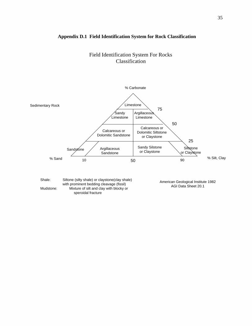
35
Appendix D.1 Field Identification System for Rock Classification
Field Identification System For RocksClassification
% Carbonate
Sedimentary Rock75
Limestone
50
% Silt, Clay
Siltstoneor Claystone
Sandy Silstoneor Claystone
Calcareous orDolomitic Siltstone
or Claystone
ArgillaceousLimestone
SandyLimestone
Calcareous orDolomitic Sandstone
Sandstone ArgillaceousSandstone
50 9010% Sand
Shale: Siltone (silty shale) or claystone(clay shale) with prominent bedding cleavage (fissil)
Mudstone: Mixture of silt and clay with blocky or speroidal fracture
American Geological Institute 1982AGI Data Sheet 20.1
25
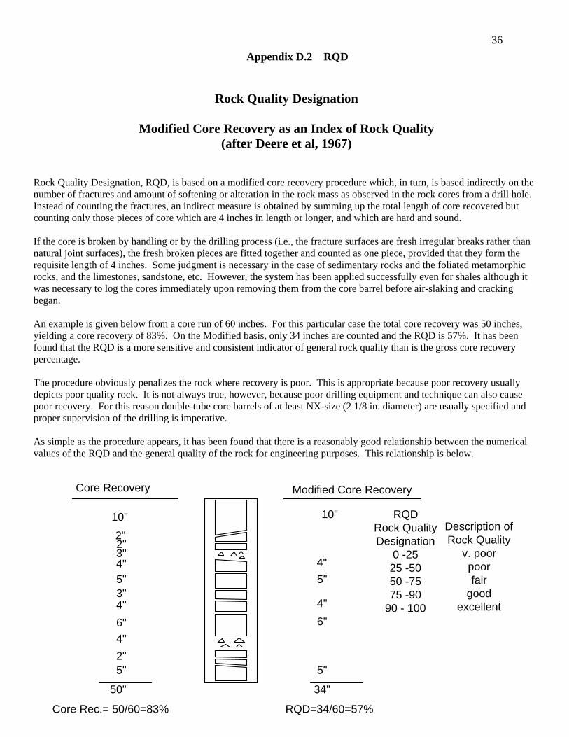
36 Appendix D.2 RQD
Rock Quality Designation
Modified Core Recovery as an Index of Rock Quality (after Deere et al, 1967)
Rock Quality Designation, RQD, is based on a modified core recovery procedure which, in turn, is based indirectly on the number of fractures and amount of softening or alteration in the rock mass as observed in the rock cores from a drill hole. Instead of counting the fractures, an indirect measure is obtained by summing up the total length of core recovered but counting only those pieces of core which are 4 inches in length or longer, and which are hard and sound.
If the core is broken by handling or by the drilling process (i.e., the fracture surfaces are fresh irregular breaks rather than natural joint surfaces), the fresh broken pieces are fitted together and counted as one piece, provided that they form the requisite length of 4 inches. Some judgment is necessary in the case of sedimentary rocks and the foliated metamorphic rocks, and the limestones, sandstone, etc. However, the system has been applied successfully even for shales although it was necessary to log the cores immediately upon removing them from the core barrel before air-slaking and cracking began. An example is given below from a core run of 60 inches. For this particular case the total core recovery was 50 inches, yielding a core recovery of 83%. On the Modified basis, only 34 inches are counted and the RQD is 57%. It has been found that the RQD is a more sensitive and consistent indicator of general rock quality than is the gross core recovery percentage. The procedure obviously penalizes the rock where recovery is poor. This is appropriate because poor recovery usually depicts poor quality rock. It is not always true, however, because poor drilling equipment and technique can also cause poor recovery. For this reason double-tube core barrels of at least NX-size (2 1/8 in. diameter) are usually specified and proper supervision of the drilling is imperative. As simple as the procedure appears, it has been found that there is a reasonably good relationship between the numerical values of the RQD and the general quality of the rock for engineering purposes. This relationship is below.
10"2"2"3"4"5"3"4"6"4"2"5"
50" 34"
5"
6"
10"
4"5"
4"
Core Recovery Modified Core Recovery
RQDRock QualityDesignation
0 -2525 -5050 -7575 -90
90 - 100
Description ofRock Quality
v. poorpoorfair
goodexcellent
Core Rec.= 50/60=83% RQD=34/60=57%
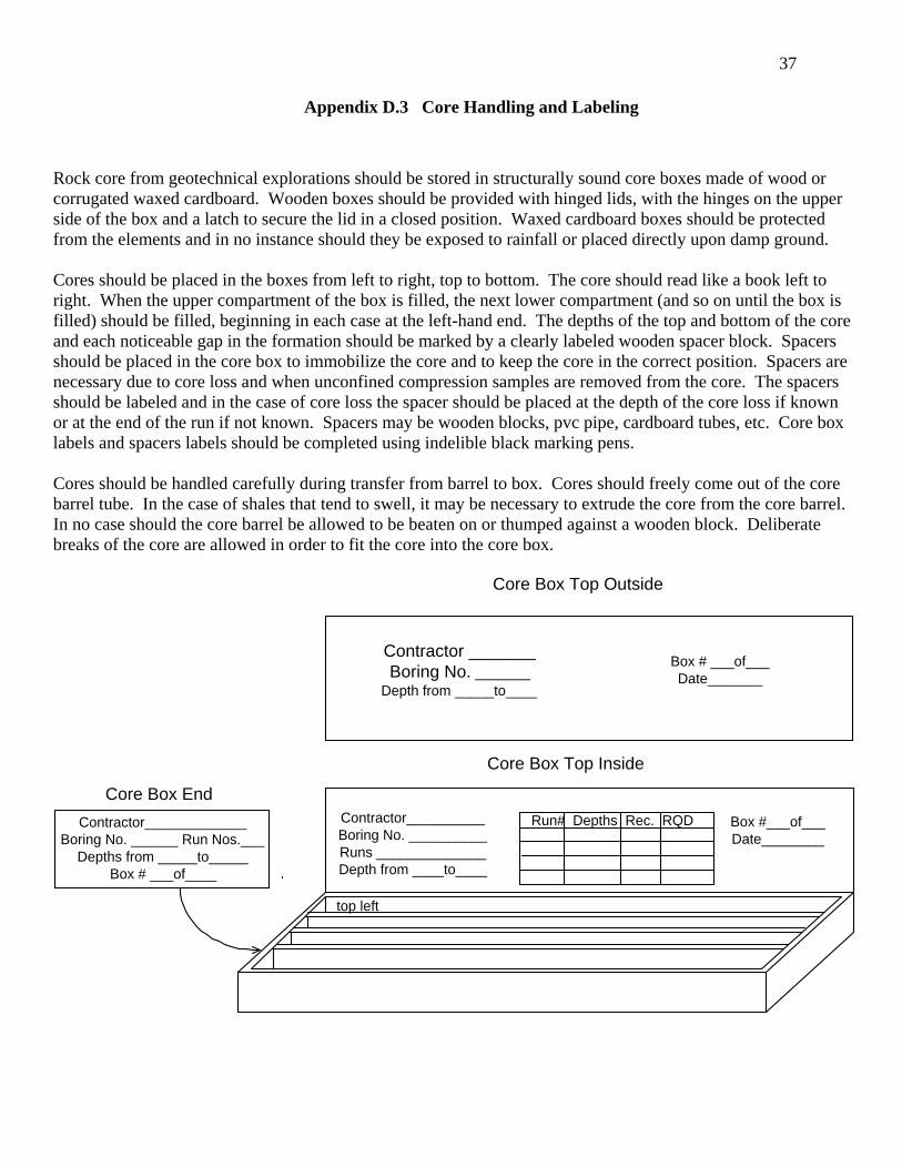
37
Appendix D.3 Core Handling and Labeling
Rock core from geotechnical explorations should be stored in structurally sound core boxes made of wood or corrugated waxed cardboard. Wooden boxes should be provided with hinged lids, with the hinges on the upper side of the box and a latch to secure the lid in a closed position. Waxed cardboard boxes should be protected from the elements and in no instance should they be exposed to rainfall or placed directly upon damp ground. Cores should be placed in the boxes from left to right, top to bottom. The core should read like a book left to right. When the upper compartment of the box is filled, the next lower compartment (and so on until the box is filled) should be filled, beginning in each case at the left-hand end. The depths of the top and bottom of the core and each noticeable gap in the formation should be marked by a clearly labeled wooden spacer block. Spacers should be placed in the core box to immobilize the core and to keep the core in the correct position. Spacers are necessary due to core loss and when unconfined compression samples are removed from the core. The spacers should be labeled and in the case of core loss the spacer should be placed at the depth of the core loss if known or at the end of the run if not known. Spacers may be wooden blocks, pvc pipe, cardboard tubes, etc. Core box labels and spacers labels should be completed using indelible black marking pens. Cores should be handled carefully during transfer from barrel to box. Cores should freely come out of the core barrel tube. In the case of shales that tend to swell, it may be necessary to extrude the core from the core barrel. In no case should the core barrel be allowed to be beaten on or thumped against a wooden block. Deliberate breaks of the core are allowed in order to fit the core into the core box.
Box #___of___Date________
Core Box Top Inside
Contractor__________Boring No. __________Runs ______________Depth from ____to____
Run# Depths Rec. RQDContractor_____________Boring No. ______ Run Nos.___
Depths from _____to_____Box # ___of____
Core Box End
Contractor _______Boring No. _______
Depth from _____to____
Box # ___of___Date_______
Core Box Top Outside
top left
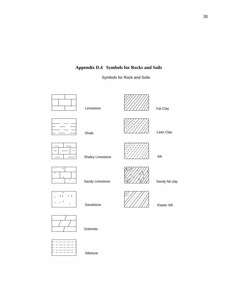
38
Appendix D.4 Symbols for Rocks and Soils
Symbols for Rock and Soils
Limestone
Shale
Shaley Limestone
Sandy Limestone
Sandstone
Dolomite
Siltstone
Fat Clay
Lean Clay
Silt
Sandy fat clay
Elastic Silt
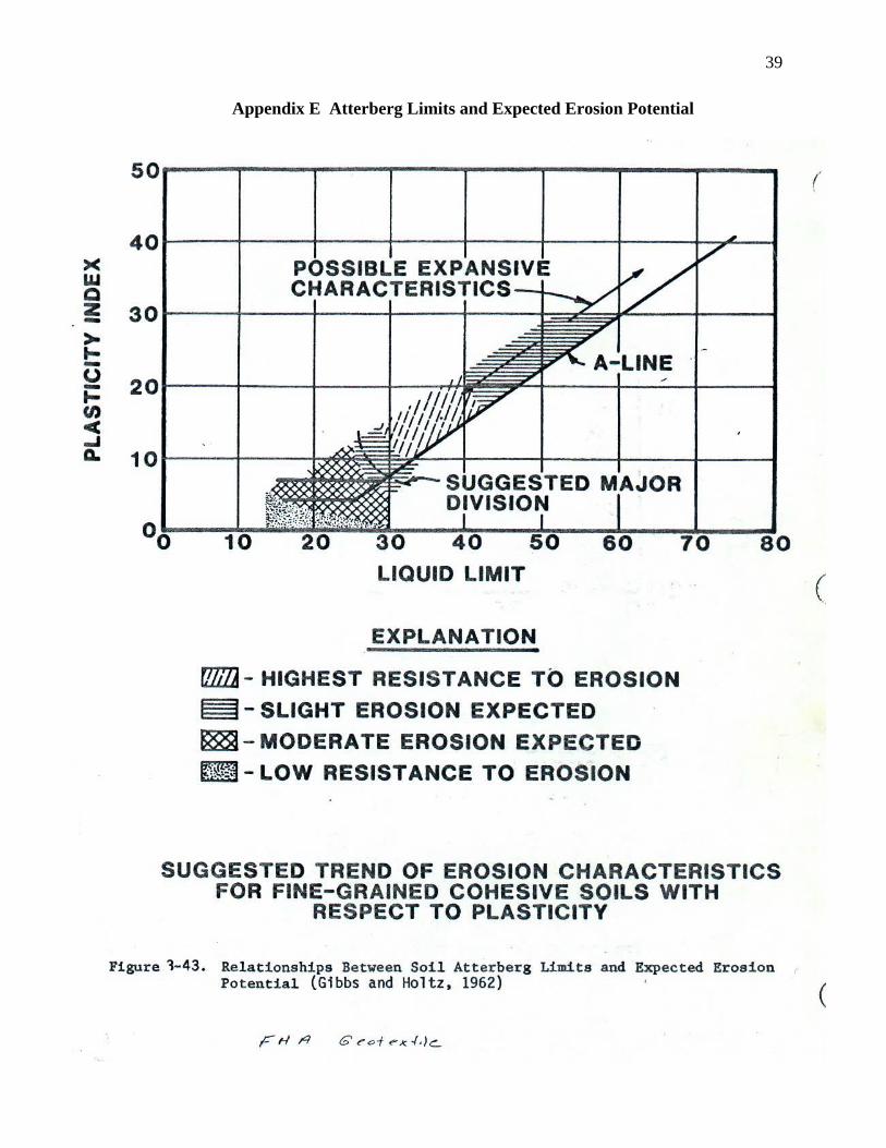
39
Appendix E Atterberg Limits and Expected Erosion Potential
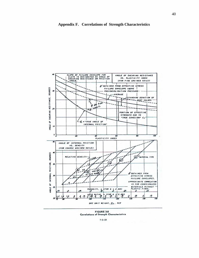
40
Appendix F. Correlations of Strength Characteristics

41
Appendix G. Example FormsG.1 Auger Logs
Form T-737-1RMO Rev. 10-95
MISSOURI DEPARTMENT OF TRANSPORTATION Division of Materials
BORING DATA
Sheet 1 of 1 Job No. County Route Design Over Skew Logged by Operator Equipment Date of Work
Bent
Station
Location
Surface Elevation
Log of Materials *
* Persons using this information are cautioned that the materials shown are determined by the equipment noted and accuracy of the "log of materials" is limited thereby and by judgment of the operator. THIS INFORMATION IS FOR DESIGN PURPOSES ONLY.
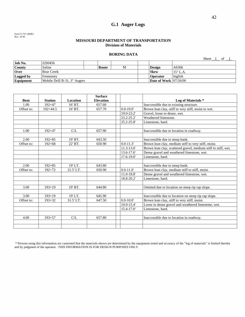
42 G.1 Auger Logs
Form T-737-1RMO Rev. 10-95
MISSOURI DEPARTMENT OF TRANSPORTATION Division of Materials
BORING DATA
Sheet 1 of 1 Job No. J2S0456 County Saline Route M Design A6366 Over Bear Creek Skew 15° L.A. Logged by Fennessey Operator Inglish Equipment Mobile Drill B-31, 3" Augers Date of Work 07/26/00
Bent
Station
Location
Surface Elevation
Log of Materials *
1.00 192+47 16' RT. 657.60 Inaccessible due to existing structure. Offset to: 192+44.5 16' RT. 657.70 0.0-19.0' Brown lean clay, stiff to very stiff, moist to wet.
19.0-23.2' Gravel, loose to dense, wet. 23.2-25.2' Weathered limestone. 25.2-25.8' Limestone, hard.
1.00 192+47 C/L 657.90 Inaccessible due to location in roadway.
2.00 192+85 19' RT. 643.50 Inaccessible due to steep bank. Offset to: 192+68 22' RT. 650.90 0.0-11.3' Brown lean clay, medium stiff to very stiff, moist.
11.3-13.6' Brown lean clay, scattered gravel, medium stiff to stiff, wet. 13.6-17.6' Dense gravel and weathered limestone, wet. 17.6-19.0' Limestone, hard.
2.00 192+85 19' LT. 643.80 Inaccessible due to steep bank. Offset to: 192+72 21.5' LT. 650.90 0.0-11.0' Brown lean clay, medium stiff to stiff, moist.
11.0-18.8' Dense gravel and weathered limestone, wet. 18.8-20.2' Limestone, hard.
3.00 193+19 19' RT. 644.80 Omitted due to location on steep rip rap slope.
3.00 193+19 19' LT. 645.90 Inaccessible due to location on steep rip rap slope. Offset to: 193+32 31.5' LT. 647.50 0.0-10.0' Brown lean clay, stiff to very stiff, moist.
10.0-15.4' Loose to dense gravel and weathered limestone, wet. 15.4-17.0' Limestone, hard.
4.00 193+57 C/L 657.80 Inaccessible due to location in roadway.
* Persons using this information are cautioned that the materials shown are determined by the equipment noted and accuracy of the "log of materials" is limited thereby and by judgment of the operator. THIS INFORMATION IS FOR DESIGN PURPOSES ONLY.
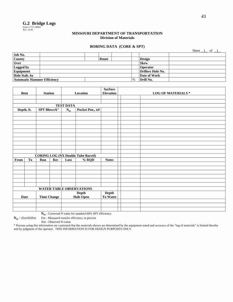
43 G.2 Bridge Logs
Form T-737-1RMO Rev. 10-95
MISSOURI DEPARTMENT OF TRANSPORTATION Division of Materials
BORING DATA (CORE & SPT)
Sheet 1 of 1 Job No. County Route Design Over Skew Logged by Operator Equipment Drillers Hole No. Hole Stab. by Date of Work Automatic Hammer Efficiency % Drill No.
Bent
Station
Location
Surface Elevation
LOG OF MATERIALS *
TEST DATA Depth, ft. SPT Blows/6" N60 Pocket Pen., tsf
CORING LOG (NX Double Tube Barrel) From To Run Rec Loss % RQD Notes
WATER TABLE OBSERVATIONS
Date
Time Change Depth
Hole Open Depth
To Water
N60 - Corrected N value for standard 60% SPT efficiency. N60 = (Em/60)Nm Em - Measured transfer efficiency in percent. Nm - Observed N-value. * Persons using this information are cautioned that the materials shown are determined by the equipment noted and accuracy of the "log of materials" is limited thereby and by judgment of the operator. THIS INFORMATION IS FOR DESIGN PURPOSES ONLY.
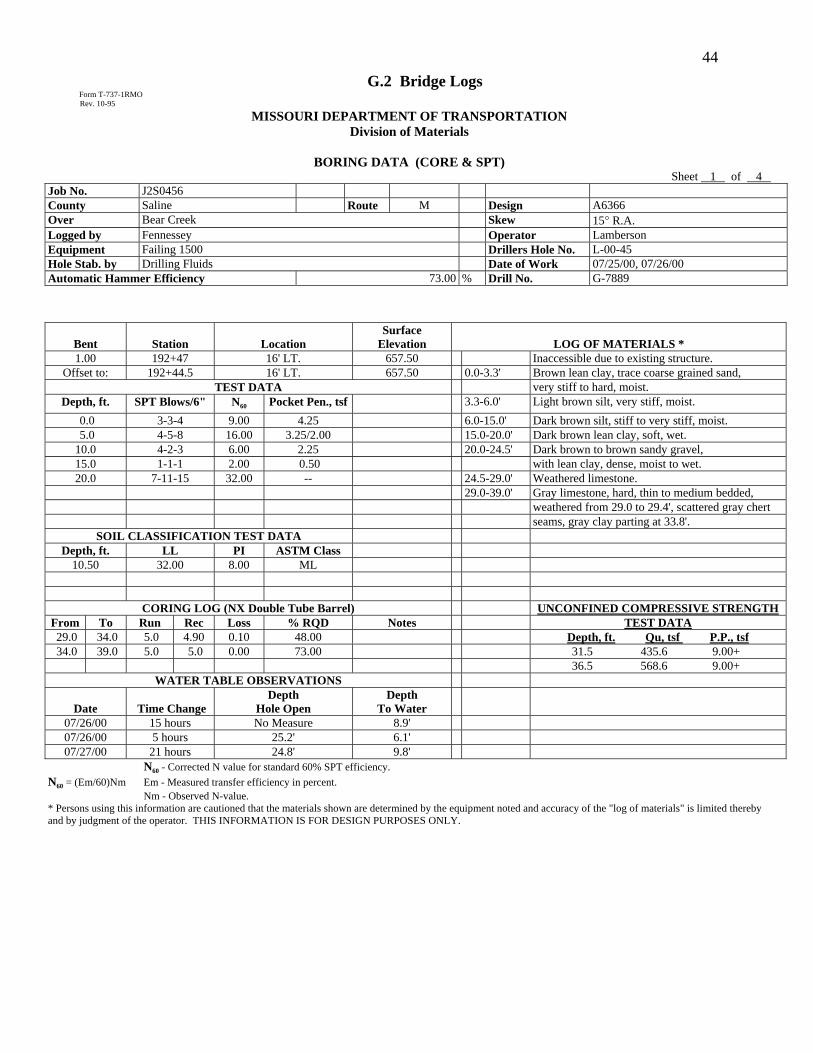
44 G.2 Bridge Logs
Form T-737-1RMO Rev. 10-95
MISSOURI DEPARTMENT OF TRANSPORTATION Division of Materials
BORING DATA (CORE & SPT)
Sheet 1 of 4 Job No. J2S0456 County Saline Route M Design A6366 Over Bear Creek Skew 15° R.A. Logged by Fennessey Operator Lamberson Equipment Failing 1500 Drillers Hole No. L-00-45 Hole Stab. by Drilling Fluids Date of Work 07/25/00, 07/26/00 Automatic Hammer Efficiency 73.00 % Drill No. G-7889
Bent
Station
Location Surface
Elevation
LOG OF MATERIALS * 1.00 192+47 16' LT. 657.50 Inaccessible due to existing structure.
Offset to: 192+44.5 16' LT. 657.50 0.0-3.3' Brown lean clay, trace coarse grained sand, TEST DATA very stiff to hard, moist.
Depth, ft. SPT Blows/6" N60 Pocket Pen., tsf 3.3-6.0' Light brown silt, very stiff, moist. 0.0 3-3-4 9.00 4.25 6.0-15.0' Dark brown silt, stiff to very stiff, moist. 5.0 4-5-8 16.00 3.25/2.00 15.0-20.0' Dark brown lean clay, soft, wet. 10.0 4-2-3 6.00 2.25 20.0-24.5' Dark brown to brown sandy gravel, 15.0 1-1-1 2.00 0.50 with lean clay, dense, moist to wet. 20.0 7-11-15 32.00 -- 24.5-29.0' Weathered limestone.
29.0-39.0' Gray limestone, hard, thin to medium bedded, weathered from 29.0 to 29.4', scattered gray chert seams, gray clay parting at 33.8'.
SOIL CLASSIFICATION TEST DATA Depth, ft. LL PI ASTM Class
10.50 32.00 8.00 ML
CORING LOG (NX Double Tube Barrel) UNCONFINED COMPRESSIVE STRENGTHFrom To Run Rec Loss % RQD Notes TEST DATA 29.0 34.0 5.0 4.90 0.10 48.00 Depth, ft. Qu, tsf P.P., tsf 34.0 39.0 5.0 5.0 0.00 73.00 31.5 435.6 9.00+
36.5 568.6 9.00+ WATER TABLE OBSERVATIONS
Date
Time Change
Depth Hole Open
Depth To Water
07/26/00 15 hours No Measure 8.9' 07/26/00 5 hours 25.2' 6.1' 07/27/00 21 hours 24.8' 9.8'
N60 - Corrected N value for standard 60% SPT efficiency. N60 = (Em/60)Nm Em - Measured transfer efficiency in percent. Nm - Observed N-value. * Persons using this information are cautioned that the materials shown are determined by the equipment noted and accuracy of the "log of materials" is limited thereby and by judgment of the operator. THIS INFORMATION IS FOR DESIGN PURPOSES ONLY.

45 G.3 Seismic Summary Sheet
DEPTH AND
DESCRIPTION
Elevation –
Wn%
Sat Kn/m3
LL
PI
ASTM Class
% #75um
Dr * **
u.s.s. c kPa
Ø° C kPa
Nblows/30cm
R.S.R. F.S. Liqu
0.00 ------ --- --- --- ---
1.00 ------ --- --- --- ---
2.00 ------ --- --- --- ---
3.00 ------ --- --- --- ---
4.00 ------ ---

46 --- --- ---
5.00 ------ --- --- --- ---
6.00 ------ --- --- --- ---
7.00 ------ --- --- --- ---
8.00 ------
JOB NO.:
Key: V Water Table
COUNTY: V Poisson’s
Ratio
ROUTE: R.S.R. Resisting
Stress Ratio
STATION: U.S.S. Undrained
Shearing Strength
BRIDGE NO.:
* From FHWA/RD-86/102 Seismic Design of Highway Bridge Foundations
** From Navdocks DM-7.1-87

47 FIGURE of