Embed Size (px)
Citation preview

Foundation Level Specialist CTFL® Automotive Software Tester (CTFL®-AuT)
English V2.0.2 Page 1 of 61 July 4th‐‐2018
Foundation Level Specialist
CTFL® Automotive Software Tester (CTFL®-AuT)
Syllabus
Version 2018 (2.0.2) dated July 4th--2018
International Software Testing Qualifications Board
Copyright Notice
This document may be copied in its entirety, or extracts made,
if the source is acknowledged.
Copyright © International Software Testing Qualifications Board (hereinafter called ISTQB®).
Foundation Level Specialist CTFL® Automotive Software Tester (CTFL®-AuT)
English V2.0.2 Page 2 of 61 July 4th‐‐2018
Copyright © 2017, German Testing Board e.V. (GTB)
The authors and the German Testing Board have agreed to the following terms of use:
Every individual and training provider may use the syllabus as a basis for training if the copyright owners are acknowledged and mentioned as the source and owners of the copyright. Furthermore, the syllabus may be used for marketing purposes only after accreditation by the ISTQB® member board.
Every individual or group of individuals may use the syllabus as a basis for articles, books or other derived publications if the authors and the German Testing Board are mentioned as the source and the owners of the copyright.
The work including all its parts is copyright-protected. The use is – if it is not explicitly allowed by the German copyright law (UrhG) – only permitted upon the approval of the entitled persons. This applies specifically to copies, adaptations, translations, microfilming, saving and processing in electronic systems, making available in public.
Registered Trademarks
CTFL® is a registered trademark of the German Testing Board (GTB) e.V. in EU only. GTB® is a registered trademark of the German Testing Board (GTB) e.V. in EU only. ISTQB® is a registered trademark of the International Software Testing Qualifications Board Automotive SPICE® is a registered trademark of the German Association of the Automotive
Industry (VDA)
Notice of Disclaimer & Limitation of Liability
No representation or warranty is made that the information is technically accurate or sufficient or conforms to any statute, governmental rule or regulation, and further, no representation or warranty is made of merchantability or fitness for any particular purpose or against infringement of intellectual property rights. In no event shall ISTQB® or GTB® be liable for lost profits or other incidental or consequential damages. ISTQB® and GTB expressly advise any and all use of or reliance upon this information provided in this document is at the risk of the user. No recommendation as to products or vendors is made or should be implied.
Foundation Level Specialist CTFL® Automotive Software Tester (CTFL®-AuT)
English V2.0.2 Page 3 of 61 July 4th‐‐2018
Overview of changes
Version Date: Note
1.0 19.01.2011 Author: Dr. Hendrik Dettmering, developed upon request of gasq GmbH
The copyright was fully transferred to German Testing Board e.V.
1.1 14.06.2015 Review of content and comparison to the German ISTQB® Certified Tester Foundation Level syllabus 2011 V1.0.1 and the ISTQB® Glossary V2.2
Release per GTB working group meeting of 15.03.2015 (Munich).
2.0 31.03.2017 Learning objectives and content on the basis of V.1.1.
Release of the (corresponding german) edition per GTB WG meeting of 31.03.2017 ( Frankfurt a. M. ).
2.0.1 (English Edition) 30.06.2017 Only minor changes in the key terms; Rework according the findings (mainly wording) from international reviewers after 1st internal alpha review in March 2017 (see acknowledgement). Corresponding English References inserted (see references)
2.0.1 (English Edition) 13.08.2017 Fine tuning of the terms after discussion with ISTQB® WG Glossary; Rework according the findings (mainly wording) from international reviewers after 2nd internal alpha review in July 2017 (see acknowledgement).
2.0.1 (English Edition) 20.08.2017 Fine tuning of the term after another discussion with ISTQB® WG Glossary; findings from late Reviewer integrated;
2.0.1 (English Edition) 15.09.2017 Findings from Reviewer by GTB working group meeting (Munich) integrated.
2.0.1 (English Edition) 16.09.2017 Rework of Chapter 3.2.2
2.0.1 (English Edition) 22.09.2017 Final Edits for GA BETA DRAFT Edition
2.0.2 (English Edition) 28.05.2018 Final Edits from BETA Review and for GA Release
2.0.2 (English Edition) 04.07.2018 Watermark removed and trademark restriction added after GA approval and for ISTQB® publication
Foundation Level Specialist CTFL® Automotive Software Tester (CTFL®-AuT)
English V2.0.2 Page 4 of 61 July 4th‐‐2018
Table of contents
Overview of changes ............................................................................................................................... 3
Acknowledgement ................................................................................................................................... 6
History of this document .......................................................................................................................... 7
Introduction .............................................................................................................................................. 8
Purpose of the document ................................................................................................................... 8
ISTQB® CTFL®-Specialist: Automotive Software Tester .................................................................. 8
Business Value ................................................................................................................................... 9
Learning objectives/Cognitive levels of knowledge ............................................................................ 9
Terms ................................................................................................................................................. 9
The exam ............................................................................................................................................ 9
Accreditation ..................................................................................................................................... 10
Level of detail ................................................................................................................................... 10
Structure of the syllabus ................................................................................................................... 11
Gender neutral wording .................................................................................................................... 11
1 Introduction (K2) [30 Min] ................................................................................................................. 12
1.1 Requirements from divergent project objectives and increasing product complexity (K2) [15 Min] ..................................................................................................................................... 12
1.2 Project aspects influenced by standards (K1) [5 Min] .............................................................. 13
1.3 The six generic phases in the system lifecycle (K1) [5 Min] ..................................................... 13
1.4 The contribution/participation of the tester in the release process (K1) [5 Min] ....................... 14
2 Standards for the testing of E/E systems (K3) [300 Min] ................................................................. 15
2.1 Automotive SPICE (ASPICE) (K3) [140 Min]............................................................................ 16
2.1.1 Design and structure of the standard (K2) [25 Min] ...........................................................16
2.1.2 Requirements of the standard (K3) [115 Min] ....................................................................18
2.2 ISO 26262 (K3) [125 Min] ......................................................................................................... 21
2.2.1 Functional safety and safety culture (K2) [20 Min] .............................................................21
2.2.2 Integration of the tester in the safety lifecyle (K2) [15 min] ................................................21
2.2.3 Structure and test specific parts of the standard (K1) [10 Min] ..........................................23
2.2.4 The influence of criticality on the extent of the test (K2) [20 Min] ......................................24
2.2.5 Application of content from CTFL® in the context of ISO 26262 (K3) [60 Min] ................24
2.3 AUTOSAR (K1) [15 Min] ........................................................................................................... 26
2.3.1 Objectives of AUTOSAR (K1) [5 Min] ................................................................................26
2.3.2 General structure of AUTOSAR (K1) [informative] [5 Min] ................................................26
2.3.3 Influence of AUTOSAR on the work of the tester (K1) [5 Min] ..........................................27
Foundation Level Specialist CTFL® Automotive Software Tester (CTFL®-AuT)
English V2.0.2 Page 5 of 61 July 4th‐‐2018
2.4 Comparison (K2) [20 Min] ......................................................................................................... 28
2.4.1 Objectives of ASPICE and ISO 26262 (K1) [5 Min] ...........................................................28
2.4.2 Comparison of the test levels (K2) [15 Min] .......................................................................28
3 Testing in a virtual environment (K3) [160 Min] ................................................................................ 30
3.1 Test environment in general (K2) [30 Min] ............................................................................... 30
3.1.1 Motivation for a test environment in the automotive development (K1) [5 Min] .................30
3.1.2 General parts of a test environment (K1) [5 Min] ...............................................................31
3.1.3 Differences between Closed-Loop and Open-Loop (K2) [15 Min] .....................................31
3.1.4 Essential interfaces, databases and communication protocols of a electronic control unit (K1) [5 Min] .........................................................................................................................32
3.2 Testing in XiL test environments (K3) [130 Min] ...................................................................... 33
3.2.1 Model in the Loop (MiL) (K2) [20 Min] ...............................................................................33
3.2.2 Software in the Loop (SiL) (K1) [10 Min] ............................................................................34
3.2.3 Hardware in the Loop (HiL) (K2) [20 Min] ..........................................................................34
3.2.4 Comparison of the XiL test environments (K3) [80 Min] ....................................................35
4 Automotive-specific static and dynamic test techniques [230 Min] .................................................. 38
4.1 Static test techniques (K3) [75 Min] .......................................................................................... 38
4.1.1 The MISRA-C: 2012 Guidelines (K2) [15 Min] ...................................................................38
4.1.2 Quality characteristics for reviews of requirements (K3) [60 Min] .....................................39
4.2 Dynamic test techniques (K3) [155 Min] ................................................................................... 40
4.2.1 Condition testing, multiple condition testing, modified condition/decision testing (K3) [60 Min] ..............................................................................................................................40
Decision outcome for the expression: ................................................................................................... 40
4.2.2 Back-to-Back-Testing (K2) [15 Min] ...................................................................................41
4.2.3 Fault injection testing (K2) [15 Min]....................................................................................41
4.2.4 Requirements-based testing (K1) [5 Min] ..........................................................................42
4.2.5 Context-dependent selection of test techniques (K3) [60 Min] ..........................................42
Annex ..................................................................................................................................................... 44
List of tables ..................................................................................................................................... 45
References ....................................................................................................................................... 45
Definitions ......................................................................................................................................... 50
Abbreviations .................................................................................................................................... 58
Index ................................................................................................................................................. 60
Foundation Level Specialist CTFL® Automotive Software Tester (CTFL®-AuT)
English V2.0.2 Page 6 of 61 July 4th‐‐2018
Acknowledgement
The German Testing Board (GTB), would like to thank the author and review team of the German version 2017, V2.0 (in alphabetical order):
Graham Bath, André Baumann, Arne Becher, Ralf Bongard (Lead Syllabus and Co-Chair WG), Kai Borgeest, Tim Burdach, Mirko Conrad, Klaudia Dussa-Zieger, Matthias Friedrich, Dirk Gebrath, Thorsten Geiselhart, Matthias Hamburg, Uwe Hehn, Olaf Janßen, Jacques Kamga, Horst Pohlmann (Lead Exam and Chair WG), Ralf Reißing, Karsten Richter, Ina Schieferdecker, Alexander Schulz, Stefan Stefan, Stephanie Ulrich, Jork Warnecke and Stephan Weißleder.
The German Testing Board (GTB) and the WG Automotive Software Tester would like to thank the extended review team of the English Versions 2018 (V.2.0.x): Graham Bath, Thomas Borchsenius, Ádám Bíró, Zsolt Csatári, Attila Farkas, Attila Fekete , Ferenc Hamori, Ádám Jezsoviczki, Gábor Kapros, Miguel Mancilla, Roland Milos, Kenji Onishii, Miroslaw Panek, Mirosław Panek, Barthomiej Predki, Stefan Stefan, Stuart Reid, Ralf Reissing, Hidetoshi Suhara, Tamás Széplakin, Eshraka Zakaria and Csaba Zelei.
Foundation Level Specialist CTFL® Automotive Software Tester (CTFL®-AuT)
English V2.0.2 Page 7 of 61 July 4th‐‐2018
History of this document
The syllabus 1.0 was developed by Dr. Hendrik Dettmering in 2010/2011 upon request from the Global Association for Software Quality AISBL (gasq).
For the review of the document selected experts from OEMs were appointed, by whom the quality and the objective of the syllabus were checked and assessed as being suitable. Therefore, this document constitutes the syllabus for the certification of the automotive software tester and is at the same time the basis for training material as well as for the exam questions for the certification.
Beginning on January 1st, 2014, the working group “Certified Automotive Software Tester” of the German Testing Board (GTB) took over further development of the syllabus to allow the rapid development of the topic and to meet the industry requirement to not only have the industry independent CORE syllabus, but also the automotive specific aspects available as an specialist to the well-established ISTQB® Foundation Level.
The version 1.1 was released on June 15th, 2015. The edition was downward compatible with version 1.0; the redundant parts accordingly ISTQB® Foundation Level syllabus was removed from Version 1.1.
Foundation Level Specialist CTFL® Automotive Software Tester (CTFL®-AuT)
English V2.0.2 Page 8 of 61 July 4th‐‐2018
Introduction1
Purpose of the document
This syllabus defines a specialist to the Foundation Level of the software test training programs of the International Software Testing Qualifications Board (in the following short ISTQB®). With the help of the syllabus at hand training providers create their course material and define a suitable teaching methodology for the accreditation. The trainees prepare for the exam with the help of the syllabus.
Further information about the history and background of the syllabus at hand can be found in the history of this syllabus.
ISTQB® CTFL®-Specialist: Automotive Software Tester
The present Specialist module to the Foundation Level of the Certified Tester training programs is directed at all persons involved in the topic of software testing in the automotive area. This includes persons in roles like testers, test analysts, test engineers, test consultants, test managers, release testers and software developers. The basic level also addresses persons in the roles of project manager, quality manager, software development manager, system analyst (business analysts), IT manager or management consultants, who wish to acquire basic knowledge and basic understanding of the topic software testing in the automotive area.
1 Major parts of the text were taken from the ISTQB® CTFL Core syllabus [21]
Foundation Level Specialist CTFL® Automotive Software Tester (CTFL®-AuT)
English V2.0.2 Page 9 of 61 July 4th‐‐2018
Business Value
In this paragraph, we will outline the business value (Business Outcomes per ISTQB®) that one can expect from a candidate with an additional certification as CTFL® Automotive Software Tester.
An CTFL® Automotive Software Tester (CTFL®-AuT) can …
AUTFL‐BO‐01 Collaborate effectively in a test team. („collaborate“)
AUTFL‐BO‐02 Adapt the test techniques known from the ISTQB® Certified Tester Foundation level (CTFL®) to the specific project requirements. („adapt“)
AUTFL‐BO‐03 Consider the basic requirements of the relevant standards (Automotive SPICE®, ISO 26262, etc.) for the selection of suitable test techniques. („select“)
AUTFL‐BO‐04 Support the test team in the risk oriented planning of the test activities and apply known elements of structuring and prioritization. („support & apply“)
AUTFL‐BO‐05 Apply the virtual test methods (e.g. HiL, SiL, MiL, etc.) in test environments. („apply“)
Learning objectives/Cognitive levels of knowledge
Each paragraph of this syllabus is assigned to a cognitive level:
K1: remember K2: understand K3: apply K4: analyse
The learning objectives define what the trainee should have learned after finishing the corresponding paragraph/chapter/module.
The content of learning objectives marked as [informative] are to be taught by the training provider within a suitable timeframe, however, they are NOT relevant for the exam.
Example: AUTFL‐2.2.3.1 Recall design and structure of ISO 26262. [informative]
Terms
The trainee should be able to reproduce all terms mentioned in the paragraph directly underneath the headline “Terms” (K1), even if it is not explicitly mentioned in the learning objectives. The definitions of the ISTQB® Glossary and the national translations in the approved versions (incl. the additional terms from the present syllabus) apply.
The exam
Based on this syllabus there is an additional exam for the domain specific certificate Foundation Level Specialist Automotive Software Tester. An exam question can ask for subject matters from several chapters of the syllabus. Generally, each exam question is assigned to one learning objective, except for those questions that are assigned to a key term. The format of the exam is Multiple Choice. Exams
Foundation Level Specialist CTFL® Automotive Software Tester (CTFL®-AuT)
English V2.0.2 Page 10 of 61 July 4th‐‐2018
can be taken directly after an accredited training course or independently (e.g. in an exam centre or as a publicly available exam). Taking part in a course is not a requirement for taking the exam.
Requirements for taking the exam
To take the exam for a Certified Automotive Software Tester candidates must have the ISTQB® Certified Tester Foundation Level (CTFL®) certificate and interest in testing in automotive development projects.
However, it is recommended that the candidate
has at least a minimum background knowledge in software development or software testing (for example six months’ experience as a system or acceptance tester or as a developer)
or has taken a course, which is accredited per the ISTQB® standard (by an ISTQB®-member-board) and/or
has gained initial experience in the testing in E/E development projects in the Automotive industry.
Accreditation
An ISTQB® Member Board may accredit training providers whose course material follows this syllabus. Training providers should obtain accreditation guidelines from the board or body that performs the accreditation. An accredited course is acknowledged to conform to this syllabus and may include an additional exam as a separate part.
Further references for training providers can be found in the annex.
Level of detail
The level of detail allows consistent training and examination. To reach this goal, this syllabus contains the following:
general learning objectives, which describe the intention of the (extended) basic level content that must be studied, including a description and, if necessary, references to further
literature learning objectives for each area of knowledge, which describe the objective cognitive result of
the training and the mindset of the participant that is to be achieved a list of terms that the participant should be able to reproduce and understand a description of the important concepts to be studied, including sources such as well-
established technical literature, standards
The syllabus is not a complete description of the field of knowledge “Testing for software oriented systems in automotive electronic development projects”. It simply reflects the necessary scope and level of detail that is relevant for the learning objectives.
Foundation Level Specialist CTFL® Automotive Software Tester (CTFL®-AuT)
English V2.0.2 Page 11 of 61 July 4th‐‐2018
Structure of the syllabus
The syllabus consists of four main chapters. Each main headline of a chapter shows the most challenging category of learning objectives/highest cognitive level, which is to be covered by the respective chapter and defines the training time, which is to be considered as a minimum for this chapter in an accredited course.
Example:
Introduction (K2) - [30 minutes]
The example shows that for chapter “Introduction (K2)” K13 and K2 are expected (but not K3) and 30 minutes are planned for the training of the material of this chapter.
Each chapter contains several sub-chapters. Each sub-chapter can also define learning objectives and a timeframe. If no time is given for a sub-chapter, it is already included in the main chapter.
Gender neutral wording
For reasons of simplifying the readability we will abstain from gender neutral differentiation, e.g. male and female users. Following an approach of equality, all role names are generally to be valid for both genders.
3 A learning objective of a higher level of taxonomy implies the learning objectives of the lower levels.
Foundation Level Specialist CTFL® Automotive Software Tester (CTFL®-AuT)
English V2.0.2 Page 12 of 61 July 4th‐‐2018
1 Introduction (K2) [30 Min]
Terms
No testing specific terms
Learning objectives
AUTFL-1.1.1 Explain and give examples of the challenges of automotive product development that arise from divergent project objectives and increasing product complexity (K2)
AUTFL-1.2.1 Recall project aspects that are influenced by standards such as time, cost, quality and project/product risks. (K1)
AUTFL-1.3.1 Recall the six generic phases in the system lifecycle per ISO/IEC 24748-1 [1]. (K1)
AUTFL-1.4.1 Recall the contribution and the collaboration of the tester in the release process. (K1)
Introduction
One of the seven principles of software testing is “Testing is context dependent” [21]. This paragraph outlines the environment of E/E development, which an “Automotive Software Tester”4 is acting in. On the one hand, divergent objectives, increasing complexity and high pressure for innovation lead to special challenges. On the other hand, standards and the lifecycle of vehicles form the framework, which the tester is working in. In the end, the tester is contributing with his work to the release of software and systems.
1.1 Requirements from divergent project objectives and increasing product complexity (K2) [15 Min]
Car makers and suppliers keep launching new car models5 more frequently as in the past and under increasing cost pressure. The following aspects influence this process:
Increasing number of models & complexity: To be able to better meet individual end customer needs, OEMs (Car producers) offer more and more car models. However, this reduces the quantities per model. To cover the resulting increases in development and production costs, producers develop several models as varieties of a common platform. The development of a platform, however, is far more complex than the development of a single model because of the need to keep control over the many possible variations.
Increasing range of functionality: The end customer requests more and more innovations without omitting existing functions, which causes the range of functions to increase.
Increasing number of configurations: The end customer wants to adjust his car model to his individual wishes. This requires many possible configurations for one car model, also in the range of functionality.
4 In the following we will only use the term „Tester”. It is to be understood as the short form of “Automotive E/E Software Tester” 5 Example from a study by the management consultancy Progenium: “In 1990, only 101 different car models were on offer …, in
2014, this number had increased to 453” [43]
Foundation Level Specialist CTFL® Automotive Software Tester (CTFL®-AuT)
English V2.0.2 Page 13 of 61 July 4th‐‐2018
Increased quality requirements: Despite increasing levels of functionality and complexity, the end customer expects at least the same or even a higher quality of the vehicle and its functions.
As the project objectives time, cost and quality are competing („Project management triangle”) car makers (OEMs) and suppliers must strive for a more efficient system development, which allows for shorter development times despite increasing complexity, increasing quality requirements and smaller budgets.
1.2 Project aspects influenced by standards (K1) [5 Min]
Standards have an influence on major project aspects such as time, cost, quality, project and product risks:
Standards increase the efficiency of processes (e.g. to reduce the development time or cost at a stable quality) by:
o uniform naming o better transparency o easier collaboration (internal and external) o increased re-usability o consolidated experience („Best Practice“)
With well-established technology guidelines [21], they help to discover risks and defects early and to resolve them.
Standards are the basis for audits. Therefore, an auditor can assess the quality of a product or process. At the same time, the auditor can check if they meet the requirements [1].
Standards are part of the contractual or regulatory provisions and guidelines.
This syllabus will, among others, look at the following standards:
standards, such as ISO 26262 [3] or Automotive SPICE(ASPICE) [2], which standardise processes and methods.
standards , such as AUTOSAR [3], which standardise products.
1.3 The six generic phases in the system lifecycle (K1) [5 Min]
The system lifecycle of a car and all included components6 begins with the product idea and ends with decommissioning. Throughout this lifecycle development processes, business processes, logistic processes and processes regarding the production technology are involved. Milestones with previously defined entry and exit criteria help to achieve mature processes. These separate and synchronise the system lifecycle7 into the following six phases [1]. (typical test activities8 in parentheses):
concept (test planning ) development (test analysis, design, implementation, execution, evaluation and report) production (end of line test) utilization (no test activities) support (maintenance test)
6 Electronic control units (hardware and software) as well as components. 7 The Safety lifecycle of the ISO 26262 runs through similar phases. 8 Test activities see also: fundamental test process [2].
Foundation Level Specialist CTFL® Automotive Software Tester (CTFL®-AuT)
English V2.0.2 Page 14 of 61 July 4th‐‐2018
retirement (migration test) The automotive industry popular product development process outlines: conception, development and production.
1.4 The contribution/participation of the tester in the release process (K1) [5 Min]
In the automotive environment, a project reaches a milestone by declaring a release and after seeing the evidences decides that the goals are reached. From this moment on, the release item meets the level of maturity needed for its use and purpose.
The release process is expected to lead to the release of the release item. The release item consists of the test item (software configuration including parameterization, if necessary also with hardware and mechanics) and the additional supporting documentation.
The tester delivers important information for the release process via the final test report [3]:
tested items and performance characteristics including their version known defects product metrics information for release recommendation (when achieving the test exit criteria) based on the
release regulation e.g. provided by a Best Practice Guideline (i.e.: test on closed terrain or public streets, installation recommendation)
Additionally, the tester participates in creating further deliverable results relevant for the release [4]:
prioritize and participate in the decision regarding changes. prioritize features (for the order of implementation).
Foundation Level Specialist CTFL® Automotive Software Tester (CTFL®-AuT)
English V2.0.2 Page 15 of 61 July 4th‐‐2018
2 Standards for the testing of E/E systems (K3) [300 Min]
Terms
Automotive SPICE (ASPICE)
Automotive SPICE (ASPICE), software qualification test (ASPICE), system qualification test (ASPICE)
ISO 26262
Automotive Safety Integrity Level (ASIL), functional safety, method table (ISO 26262),
AUTOSAR
No testing specific terms
Comparison
No testing specific terms
Learning objectives
Automotive SPICE (ASPICE)
AUTFL-2.1.1.1 Recall the two dimensions of Automotive SPICE (ASPICE). (K1)
AUTFL-2.1.1.2 Recall the 3 process categories and 8 process groups of ASPICE [informative]. (K1)
AUTFL-2.1.1.3 Explain the Capability levels 0 to 3 of ASPICE. (K2)
AUTFL-2.1.2.1 Recall the purpose of the 5 test relevant processes of ASPICE. (K1)
AUTFL-2.1.2.2 Explain the meaning of the four rating levels and the capability indicators of ASPICE from the testing perspective. (K2)
AUTFL-2.1.2.3 Explain the requirements of ASPICE for the test strategy including the regression test strategy. (K2)
AUTFL-2.1.2.4 Recall the requirements of ASPICE for the test documentation. (K1)
AUTFL-2.1.2.5 Design a verification strategy (in contrast to a test strategy) and criteria for unit verification. (K3)
AUTFL-2.1.2.6 Explain the different traceability requirements of ASPICE from the testing perspective. (K2)
ISO 26262
AUTFL-2.2.1.1 Explain the objective of functional safety for E/E systems. (K2)
AUTFL-2.2.1.2 Recall testers’ contribution for the safety culture. (K1)
AUTFL-2.2.2.1 Present the role of the tester in the framework of the safety lifecycle per ISO 26262. (K2)
AUTFL-2.2.3.1 Recall the design and structure of ISO 26262. [informative]9
9 Not mandatory for exams
Foundation Level Specialist CTFL® Automotive Software Tester (CTFL®-AuT)
English V2.0.2 Page 16 of 61 July 4th‐‐2018
AUTFL-2.2.3.2 Recall the name of volumes (part titles) of ISO 26262 that are relevant to the tester. (K1)
AUTFL-2.2.4.1 Recall the criticality levels of ASIL. (K1)
AUTFL-2.2.4.2 Explain the influence of ASIL on applicable test design techniques and test types for static and dynamic tests and the resulting test extent. (K2)
AUTFL-2.2.5 To be able to interpret the method tables of the ISO 26262. (K3)
AUTOSAR
AUTFL-2.3.1 Recall the objectives of AUTOSAR. (K1)
AUTFL-2.3.2 Recall the general design of AUTOSAR [informative]10. (K1)
AUTFL-2.3.3 Recall the influence of AUTOSAR on the work of the tester. (K1)
Comparison
AUTFL-2.4.1 Recall the different objectives of ASPICE and ISO 26262 (K1).
AUTFL-2.4.2 Explain the differences between ASPICE and ISO 26262 and CTFL® regarding the test levels (K2).
2.1 Automotive SPICE (ASPICE) (K3) [140 Min]
Introduction
Process improvement follows the approach that the quality of a system depends on the quality of the development process. Process models in this case offer an option for improvements by measuring the process capability of an organization compared to the model. Furthermore, the model serves as the framework for the improvement of the processes of an organization using the assessment results [5].
From 2001 on, the SPICE11 User Group and the AUTOSIG (Automotive Special Interest Group) developed Automotive SPICE (ASPICE). Since its publication in 2005, the standard has been well established in the automotive industry.
In July 2015, the German Association of the Automotive Industry (VDA) released ASPICE Version 3.0 [9]. From 2017 on the improved version V.3.1. of ASPICE 3.1 will replace [6] the established Version 2.5 [2]. All statements made in this paragraph therefore refer to Version 3.1 of ASPICE[47].
2.1.1 Design and structure of the standard (K2) [25 Min]
2.1.1.1 The two dimensions of ASPICE
ASPICE defines an assessment model with two dimensions:
In the process dimension, ASPICE defines the Process Reference model. These serve as a reference to compare the organisations processes against so that they can be assessed and improved. For each process, ASPICE defines the purpose and the results as well as the required actions (base practices)
10 Not mandatory for exams. 11 Acronym for „Software Process Improvement and Capability Determination“
Foundation Level Specialist CTFL® Automotive Software Tester (CTFL®-AuT)
English V2.0.2 Page 17 of 61 July 4th‐‐2018
and work results (work products). If an organization needs further reference processes beyond ASPICE, these can be taken e.g. from ISO/IEC 12207 [10] or ISO/IEC 15288 [11].
In the capability dimension ASPICE defines a number of process attributes. These provide the measurable features of the process capability. For each process, there are process-specific as well as generic attributes. ISO/IEC 33020 serves as a basis for the assessment of the process capability [39].
With the help of this model it is possible to assess the processes (process dimension) regarding their capability (capability dimension).
2.1.1.2 Process categories in the process dimension
ASPICE groups the processes into 8 process groups then the process groups into 3 process categories [9][47]:
The primary processes include all processes that serve as key processes of the company:
Acquisition (ACQ) of products and/or services Supply (SPL) of products and/or services System engineering (SYS) Software engineering (SWE)
The supporting processes include all processes that support other processes:
Supporting processes (SUP)
The organizational processes include all processes that support the company objectives:
Management (MAN) of a project or process Process improvement (PIM) Reuse (REU) of systems and components
For the tester, the process groups system development (SYS) and software development (SWE) are of special interest. These build the processes of the Automotive SPICE V-model ([9] Annex D “Key Concepts”).
2.1.1.3 Capability levels in the capability dimension
The assessor assesses the process capability with the help of a six-level assessment system (display of levels). ASPICE defines the capability levels 0 to 312 as follows [9][47]:
Level 0 (incomplete process): The process does not exist or does not achieve the purpose of the process. Example: The tester only checks a minor part of the requirements.
Level 1 (performed process): The implemented process achieves its process purpose (but maybe executed inconsistently). Example: There is no complete planning visible for the test process. However, the tester can show the level of fulfilment of the requirements.
Level 2 (managed process): The project plans and supervises the process in its execution. Under certain circumstances, it adapts the course of action during execution to meet the objective. The requirements for the work products are defined. A project member checks the work products and approves them. Example: The test manager defines the test objectives, plans the test activities and supervises the process. In case of deviations, he reacts accordingly.
12 The capability level 4 and 5 are currently not in the focus of the automotive industry.
Foundation Level Specialist CTFL® Automotive Software Tester (CTFL®-AuT)
English V2.0.2 Page 18 of 61 July 4th‐‐2018
Level 3 (established process): The project uses a standardized process, and findings are used to constantly improve. Example: There is a general test strategy for the whole organization. After the test completion (see fundamental test process) the test manager helps to further develop it.
2.1.2 Requirements of the standard (K3) [115 Min]
2.1.2.1 Test specific processes
ASPICE defines test processes according to all processes of the software and system development [8]:
The process software unit verification (SWE.4) requires static and dynamic testing. It assesses the components of the software based on its detailed design (SWE.3).
The software integration test (SWE.5) assesses the integrated software based on the software architecture (SWE.2).
The software qualification test (SWE.6) assesses the integrated software based on the software requirements (SWE.1).
The system integration test (SYS.4) assesses the integrated system based on the system architecture (SYS.3).
The system qualification test (SYS.5) assesses the integrated system based on the system requirements (SYS.2).
2.1.2.2 Assessment levels and capability indicators
An assessor can assess the process capability via capability indicators. ASPICE defines them for 9 process attributes (PA). For the capability levels 1 to 3, they are defined as follows (using the example of SWE.6 in parentheses) [9], [47]:
PA 1.1: Process performance (the tester orients him-/herself by means of the fundamental test process).
PA 2.1: Performance management (the tester plans, supervises and controls the test activities among other things).
PA 2.2: Work product management (the tester checks the quality of the test documentation among other things).
PA 3.1: Process definition (the person responsible for the test process defines a general project strategy among other things).
PA 3.2: Process deployment (the tester applies the test strategy defined in PA 3.1).
For the process execution (PA 1.1) ASPICE defines two types of indicators: base practices (BP) and work products (WP). In addition generic practices (GP) and resources are defined. The assessment of the process attributes is based on the implementation level of the indicators in four rating levels [9], [47]:
N (None): not fulfilled (0% up to ≤ 15%)
P (Partly): partly fulfilled (> 15% up to ≤ 50%) L (Largely): largely fulfilled (> 50% up to ≤ 85%) F (Fully): fully fulfilled (> 85% up to ≤ 100%)
For a process to reach a certain capability level, the indicators of the capability level to be achieved must be “largely fulfilled (L)”. The indicators of the lower capability levels must be “fully fulfilled (F)”.
Foundation Level Specialist CTFL® Automotive Software Tester (CTFL®-AuT)
English V2.0.2 Page 19 of 61 July 4th‐‐2018
2.1.2.3 Test strategy and regression test strategy
As a base practice, ASPICE requires a test strategy13 for each test specific process (see 2.1.2.1). The test manager develops this within the test planning. Test guidelines, project objectives as well as contractual and regulatory requirements build the basis for this.
The tester knows early testing as a principle of testing. This also applies to the testing of software in the automotive environment. However, another aspect comes into play here because test environments at higher test levels are significantly more expensive. For example, for the testing at higher levels, especially developed and embedded hardware is necessary (e.g. as a prototype or unique model). The test strategy defines the level-specific test environments, but also which tests the tester is required to perform in which test environments.
The regression test strategy is an essential part of the test strategy. The challenge here lies in the economically sensible choice of the test cases (“added value of testing”). The regression strategy defines the objective and the technique for the choice of the regression tests. For example, the choice can be risk-based. An impact analysis helps to identify the areas the tester must focus on with regression tests. However, the test manager may also ask the tester to repeat all automated test cases for each release.
2.1.2.4 Test documentation in ASPICE
For the documentation of the test activities, ASPICE requires many work products (WP) that are known to the tester from CTFL® [9]:
WP 08-50: Test specification (containing test design, test case and test procedure specification)
WP 08-52: Test plan according to ISO/IEC/IEEE 29119-3 [34] and included strategy (WP 19-00)
WP 13-50: Test result, test log, incident/deviation report and test summary report
For each work product, ASPICE defines examples of characteristics and content. An assessor can evaluate those by spot checking. For an assessor they serve as an objective indicator for a process execution.
For the test plan ASPICE directly refers to ISO/IEC/IEEE 29119-314. This standard also provides templates that can be used for other required work products and can be adapted for a particular purpose. It must be ensured that within the context it contributes to the intended purpose of the processes.
2.1.2.5 Verification strategy and criteria for unit verification (SWE.4)
For the verification of the software units (SWE.4) ASPICE requires a verification strategy15. In the case of SWE.5/SWE.6/SYS.4/SYS.5 test-specific processes ASPICE requires test strategy (see 2.1.2.3). The test strategy “only” looks at dynamic tests. This is an addition to the verification strategy, which also considers code review and static analysis (Both techniques are known as “static tests” from CTFL®).
The tester verifies compliance with the software detailed design and with the functional and non-functional requirements according to the verification strategy. The strategy defines how the tester provides the evidence. Therefore, the tester can use different combinations of static and dynamic test techniques to verify the units.
13 Per CTFL [2] the project specific test strategy is also known as test technique. 14 This replaces the IEEE 829:1998 and the IEEE 829:2008 that are still used in ISTQB syllabi. 15 For the terms „verification strategy“ and „test strategy“, in ASPICE the term „strategy“ is used as opposed to project specific
„technique“ in ISTQB.
Foundation Level Specialist CTFL® Automotive Software Tester (CTFL®-AuT)
English V2.0.2 Page 20 of 61 July 4th‐‐2018
If a developer changes a unit, the tester must also evaluate this change. Therefore, the strategy for the verification of units also includes a regression strategy. This includes the verification of the changed code, the confirmation testing as well as the repeated verification of the non-changed parts (static and dynamic regression tests).
In SWE.4.BP.2 ASPICE requires the development of criteria for verification of units. These criteria define what needs to be fulfilled. Therefore, a tester can evaluate how much the unit fulfils the non-functional requirements and matches the detailed design. The following criteria are possible criteria for the verification of units:
Unit test cases (including test data) Objectives for the test coverage (for example decision coverage) Tool-supported static analysis, which assesses the compliance with coding standards (such
as MISRA-C, see 4.1.1) Code reviews for units or parts of units, which cannot be assessed by tool-supported static
analysis.
According to Automotive SPICE (ASPICE), the documentation of the verification strategy is part of the test plan ([13] paragraph 6.2.7) on unit level. The content is divided according to ISO/IEC/IEEE 29119-3 and enhanced by the aspects of the static tests.
2.1.2.6 Traceability in Automotive SPICE (ASPICE)
As in CTFL® Core Sylabus [21], ASPICE also requires bidirectional traceability16. This allows the tester:
to analyse impact to evaluate coverage or to track status.
Moreover, this allows the tester(´s) to ensure the consistency between the linked elements, textually as well as semantically.
ASPICE differentiates between vertical and horizontal traceability [9]:
Vertically, ASPICE requires stakeholder requirements to be linked to the software components. In doing so, the link over all levels of development ensures a consistency between the related work products.
Horizontally, ASPICE also requires traceability and consistency, in this case between the work results of the development and the corresponding test specifications and results.
In addition, the basic practice SUP.10.BP8 requires bidirectional traceability between change requests and work products affected by the change requests. Change request is initiated by a problem, bidirectional traceability is required between change requests and the corresponding problem report. Because of the occasionally large number of links, a consistent chain of tools can be helpful. This allows the tester to efficiently create and manage the dependencies.
16 In the following, the term traceability will always imply the bidirectional traceability.
Foundation Level Specialist CTFL® Automotive Software Tester (CTFL®-AuT)
English V2.0.2 Page 21 of 61 July 4th‐‐2018
2.2 ISO 26262 (K3) [125 Min]
2.2.1 Functional safety and safety culture (K2) [20 Min]
2.2.1.1 Objective of functional safety for E/E systems
The functional and technical complexity of embedded systems is constantly rising. At the same time, powerful software based electrical and electronic systems allow new complex functionalities such as the automation of driving functions in the car.
Due to the high complexity, the risk of an erroneous action happening during development is increasing. The consequence can be a (non-detected) fault state in the system. For systems with an inherent risk potential for life and limb, the person responsible for safety therefore needs to analyse potential risks. If there is an actual risk, he identifies suitable measures to mitigate their possible impact to an acceptable level of risk.
The methods for the execution of such analysis are summarized in the standard for the functional safety. The foundation standard is the IEC 61508. The International Organization for Standardization (ISO) adapted ISO 26262 from this standard.
According to ISO 26262, Functional Safety is defined as absence of unreasonable risk due to hazards caused by malfunction behaviour of E/E systems. In this sense, the term is to be differentiated from other safety terms such as informational safety, product safety or work safety [ISO 26262] [IEC 61508]. Safety in the working environment and cybersecurity are not in the focus of ISO 26262. Lack of Cybersecurity can endanger Functional Safety and cybersecurity contributes to product safety.
2.2.1.2 Contribution of the tester to the safety culture
Within the product development according to ISO 26262 it is not enough to monitor your own organization´s processes. All participants need to live a process-independent approach. Everybody must understand their impact on the development process and the safety of the final product. This includes external partners and suppliers.
The participants must understand that their own actions do not happen independently of other processes. Each step of the development constitutes an essential contribution to the compliance with and the implementation of the Functional-Safety-relevant requirements. This responsibility does not end with the product launch. It continues until the end of the system lifecycle.
The tester contributes to the safety culture by participating responsibly in all software development life cycle phases and by carrying out his work with a continuous view of the overall context of the product development [ISO 26262]
2.2.2 Integration of the tester in the safety lifecyle (K2) [15 min]
The safety lifecycle describes the phases of a safety-oriented product development. It starts with the first product idea and the search for possible risks. After the specification of resulting safety requirements, the implementation into a specific product follows. The cycle ends with the disposal of the product at the end of its life (see also chapter 1.3).
The safety lifecycle according to ISO 26262 goes through the following phases:
1st phase: Product concept 2nd phase: Product development 3rd phase: Product production and maintenance (after the “release for production”)
Foundation Level Specialist CTFL® Automotive Software Tester (CTFL®-AuT)
English V2.0.2 Page 22 of 61 July 4th‐‐2018
The tester at supplier works mostly in the first two phases. Changes to the product within the third phase lead to a return to the first or second phase, depending on their extent. Therefore, the tester also participates in modifications. Based on the safety-related requirements (see chapter 2.2.4) he designs the test cases and select the test techniques for the verification within the product development and the validation of these requirements. The tester will then perform those in the relevant sub-phases of the product development.
The activities of test planning normally take place within the concept phase. Adjustments in the resulting documents (for example in the test plan or the test specifications) can, however, be necessary in any phase. The test execution mostly takes place at the transfer between the individual sub-phases of the product development. For example, between the implementation and the software integration as well as further on to the hardware software integration. Moreover, the tester significantly contributes to the transfer to the third phase with his test activities [ISO 26262]
Foundation Level Specialist CTFL® Automotive Software Tester (CTFL®-AuT)
English V2.0.2 Page 23 of 61 July 4th‐‐2018
2.2.3 Structure and test specific parts of the standard (K1) [10 Min]
2.2.3.1 Design and structure of the standard [informative]
ISO 26262 consists of 10 volumes (parts):
Vocabulary (volume 1), Management of functional safety (volume 2), The phases of the safety lifecycle:
o Concept phase (volume 3) o Product development for entire system, hardware and software (volumes 4-6) o Production and operation (volume 7)
Supporting processes (volume 8) ASIL and safety-oriented analysis (volume 9) Guidelines for the application of ISO 26262 (volume 10).
Apart from volume 1 and volume 10, each volume includes normative content. Part of this is:
A general introduction, The scope of application, Normative references and Requirements for the compliance with the standard.
These are followed by the specific topics of the corresponding volume. The structure of their description is the same in each volume. The activities that are to be carried out are described via a similarly structure in all volumes (parts) [ISO 26262]:
Objective General information Introductory information Pre-requirements Further supporting information Requirements and recommendations Work results
2.2.3.2 Relevant volumes (parts) for the tester
For the software tester, the software verification and (at least partly) also the system validation is paramount. Apart from Volume 1 (terminology), several other volumes (parts) are also of special interest: Volumes 4 and 6 provide detailed information and requirements regarding recommended measures of the software verification. This applies to the selection, the design and the implementation as well as to the execution of the corresponding verification measures.
In doing so, these volumes focus on the test and verification specific aspects of the system (Volume 4, including system validation) and software level (Volume 6). If hardware-specific aspects are also relevant for this work, the tester will find those in Volume 5. Aspects concerning hardware as well as software are considered within the scope of the hardware software interface (volumes 4,5 and 6).
Volume 8 of ISO 26262 forms a special position as this describes the process specific characteristics of the verification at all test levels. In addition, it contains requirements for important supporting processes for the tester, such as for example the documentation and the qualification of tools. [ISO 26262]
Foundation Level Specialist CTFL® Automotive Software Tester (CTFL®-AuT)
English V2.0.2 Page 24 of 61 July 4th‐‐2018
2.2.4 The influence of criticality on the extent of the test (K2) [20 Min]
2.2.4.1 The criticality levels of ASIL
The ASIL (”Automotive Safety Integrity Level“) is a measure for the required risk reduction by measures of the Functional Safety. Such measures can for example be an independent safety function for the supervision of an E/E system or the implementation of specifically defined methods. For higher levels of risk, more elaborate measures can be necessary.
At the beginning of the project, an expert team carries out the Hazard analysis and the risk assessment for the product. For each risk identified by this analysis, he/she determines an ASIL with the help of one of the methodologies defined in the standard. In the next step, he drafts safety goals and safety requirements. These use the same ASIL as the risk they are based on.
The ISO 26262 defines four levels: from ASIL A for low, up to ASIL D for high safety requirements.
If the Hazard Analysis and Risk assessment leads to requirements below ASIL A, in terms of the standard those are not safety relevant. These requirements will be covered by complying with the existing quality management (QM). [ISO 26262]
2.2.4.2 Influence of ASIL on test techniques, test types and the extent of the test
The determined ASIL influences directly the extent of the tests to be implemented by the tester. Depending on the particular level of the ASIL, the ISO 26262 standard recommends the execution of different measures or packages of measures. In doing so, the rule is that the standard for higher ASIL recommends more extensive and more detailed measures. For lower level ASIL, the execution of the specified measures is often optional.
ISO 26262 specifies three level of recommendations: no recommendation, recommended, and highly recommended. For “no recommendation”, the standard does not provide any recommendation for or against the use of the corresponding measure. It can be used as a support without any concern. However, its execution does not replace the measures recommended or highly recommended by ISO.
For the tester, this means that the standard recommends specific test design techniques and test types for functional safety-relevant systems depending on the ASIL. The tester can only decide independently within the framework of the standard regarding this special case. For example, use of equivalence partitioning and boundary value analysis are recommended for ASIL A. On the other hand, for an ASIL B or higher, those techniques are highly recommended (see also chapter 2.2.5).
The ASIL is not a characteristic of the entire product. It is connected to a specific safety objective and the resulting safety requirements. Therefore, there can be significantly different test efforts for safety requirements with different ASILs for one product. This must be taken into consideration by the tester when planning the extent of the tests. [ISO 26262]
2.2.5 Application of content from CTFL® in the context of ISO 26262 (K3) [60 Min]
ISO 26262 offers the tester specific recommendations for his test activities in form of method tables. These tables can be found in volumes (parts) 4, 5, 6 and 8. Apart from Functional Safety specific recommendations for processes and activities, they also include the techniques to be used by the tester.
Foundation Level Specialist CTFL® Automotive Software Tester (CTFL®-AuT)
English V2.0.2 Page 25 of 61 July 4th‐‐2018
In this context, the standard uses the term “method” related to all applicable techniques or activities. At this point, the Functional Safety terminology differs slightly from the terms of the ISTQB®. For the tester, the following methods of the ISO 26262 are of special interest:
Test design techniques (e.g. equivalence partitioning, boundary value analysis, …) Techniques of the test execution (e.g. simulation or prototype of part or system) Test types (e.g. non-functional tests such as performance test, soak test, ..)
Test environments (e.g. HiL, vehicle, …) Static test techniques (e.g. reviews, static analysis, …)
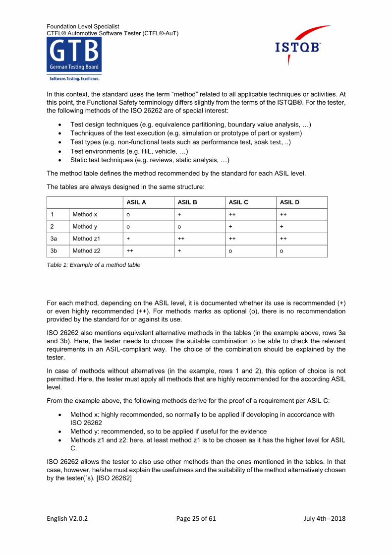
The method table defines the method recommended by the standard for each ASIL level.
The tables are always designed in the same structure:
ASIL A ASIL B ASIL C ASIL D
1 Method x o + ++ ++
2 Method y o o + +
3a Method z1 + ++ ++ ++
3b Method z2 ++ + o o
Table 1: Example of a method table
For each method, depending on the ASIL level, it is documented whether its use is recommended (+) or even highly recommended (++). For methods marks as optional (o), there is no recommendation provided by the standard for or against its use.
ISO 26262 also mentions equivalent alternative methods in the tables (in the example above, rows 3a and 3b). Here, the tester needs to choose the suitable combination to be able to check the relevant requirements in an ASIL-compliant way. The choice of the combination should be explained by the tester.
In case of methods without alternatives (in the example, rows 1 and 2), this option of choice is not permitted. Here, the tester must apply all methods that are highly recommended for the according ASIL level.
From the example above, the following methods derive for the proof of a requirement per ASIL C:
Method x: highly recommended, so normally to be applied if developing in accordance with ISO 26262
Method y: recommended, so to be applied if useful for the evidence Methods z1 and z2: here, at least method z1 is to be chosen as it has the higher level for ASIL
C.
ISO 26262 allows the tester to also use other methods than the ones mentioned in the tables. In that case, however, he/she must explain the usefulness and the suitability of the method alternatively chosen by the tester(´s). [ISO 26262]
Foundation Level Specialist CTFL® Automotive Software Tester (CTFL®-AuT)
English V2.0.2 Page 26 of 61 July 4th‐‐2018
2.3 AUTOSAR (K1) [15 Min]
Introduction
AUTOSAR is an acronym for „AUTomotive Open System ARchitecture“ and the development partnership behind it. This partnership was established in 2003 and includes mainly producers and suppliers of the automotive industry. The goal of the partnership was: “To create and establish a freely available standard for a software architecture in the vehicle environment”. Therefore, this standard is aimed at addressing the increasing importance and complexity of the software [14]. Today, AUTOSAR is a globally established standard for E/E systems. Therefore, the tester will certainly come into contact with products of AUTOSAR. Therefore, it is important for tester(´s) to know the objectives, the basic design and the points of contact with tester(´s) work.
2.3.1 Objectives of AUTOSAR (K1) [5 Min]
The following project objectives for AUTOSAR are led by the principle “Collaboration in the standards, competition in the implementation”: [14, 15]:
1. Supports the transferability (portability) of software 2. Supports the scalability to different vehicle and platform variants 3. Supports different functional domains 4. Definition of an open architecture, that is maintainable as well as adjustable and expandable 5. Supports the development of reliable systems - characterized by availability, reliability,
safety(functional as well as with regards to cybersecurity, “safety & security”) - integrity and maintainability
6. Supports a sustainable use of natural resources 7. Supports the collaboration between various partners 8. Standardization of basic software functionality of automotive electronic control units (ECUs) 9. Support of applicable automotive standards for vehicles and state of the art technologies.
2.3.2 General structure of AUTOSAR (K1) [informative] [5 Min]
The architecture of AUTOSAR consists of three separate layers:
The layer that is independent from the hardware, containing with the AUTOSAR software components (SW-C).
The hardware-oriented layer with standardized basic software (BSW). The abstraction layer with the AUTOSAR runtime environment (RTE). This controls the data
exchange within and outside of the electronic control units and implements it between the software components as well as between software components and basic software.
A further aspect is the AUTOSAR methodology for the harmonized development of control unit software. In this, OEM´s and suppliers exchange information about description files through AUTOSAR templates (so-called “arxml-files”). [14, 16]:
The “ECU configuration description” includes data for the integration of the SW-C on the electronic control unit.
The “system configuration description” includes data for the integration of all control units in one vehicle.
Foundation Level Specialist CTFL® Automotive Software Tester (CTFL®-AuT)
English V2.0.2 Page 27 of 61 July 4th‐‐2018
The “ECU extract” includes the data from the “system configuration description” for a single electronic control unit.
2.3.3 Influence of AUTOSAR on the work of the tester (K1) [5 Min]
AUTOSAR influences the work of the tester,especially at the following test levels18:
Software component test and software integration test in a virtual environment (e.g. software in the loop): With the help of a virtual BSW and RTE, a tester can test the SW-Components of the application early [17, 18].
Software test and software integration tests in the real control unit: Here, the tester gets access to the communication on the RTE. With this, the tester can measure and stimulate the behaviour of the SW-C at runtime [19].
The AUTOSAR acceptance test is a test of the software system which ensures the compliance of the AUTOSAR functionality at the communication and application levels. The execution of the AUTOSAR acceptance test is optional [20, 21].
System integration test: Functional integration and connection of different electronic control units (for example, also in the vehicle). By simulating missing, probably distributed functionalities, the tester can assess the system behaviour early [17].
18 acc. Test levels; see also 2.4.2
Foundation Level Specialist CTFL® Automotive Software Tester (CTFL®-AuT)
English V2.0.2 Page 28 of 61 July 4th‐‐2018
2.4 Comparison (K2) [20 Min]
2.4.1 Objectives of ASPICE and ISO 26262 (K1) [5 Min]
There are several standards that propose requirements to the product development. Typically, these highlight different aspects in the development. The ISO 26262 and ASPICE are compared here regarding their objectives.
ISO 26262 [3] has the objective of avoiding risks from systematic failures in the development and hardware failures in the operation by presenting suitable requirements and processes. For the development of E/E systems, it defines the requirements for the processes and methods to be used by the tester. These depend on the ASIL level of the item.
ASPICE [9] serves the purpose of determining the capability of the product development process within the framework of assessments. To do so, ASPICE defines assessable criteria for these processes. In contrast to the ISO 26262, these are independent of the criticality and of the products ASIL level.
2.4.2 Comparison of the test levels (K2) [15 Min]
Both ISO 26262 and ASPICE describe test levels. However, these are not completely consistent with the test levels from CTFL® [21]. Therefore, for an efficient and effective collaboration, testers should have a common understanding of all test levels.
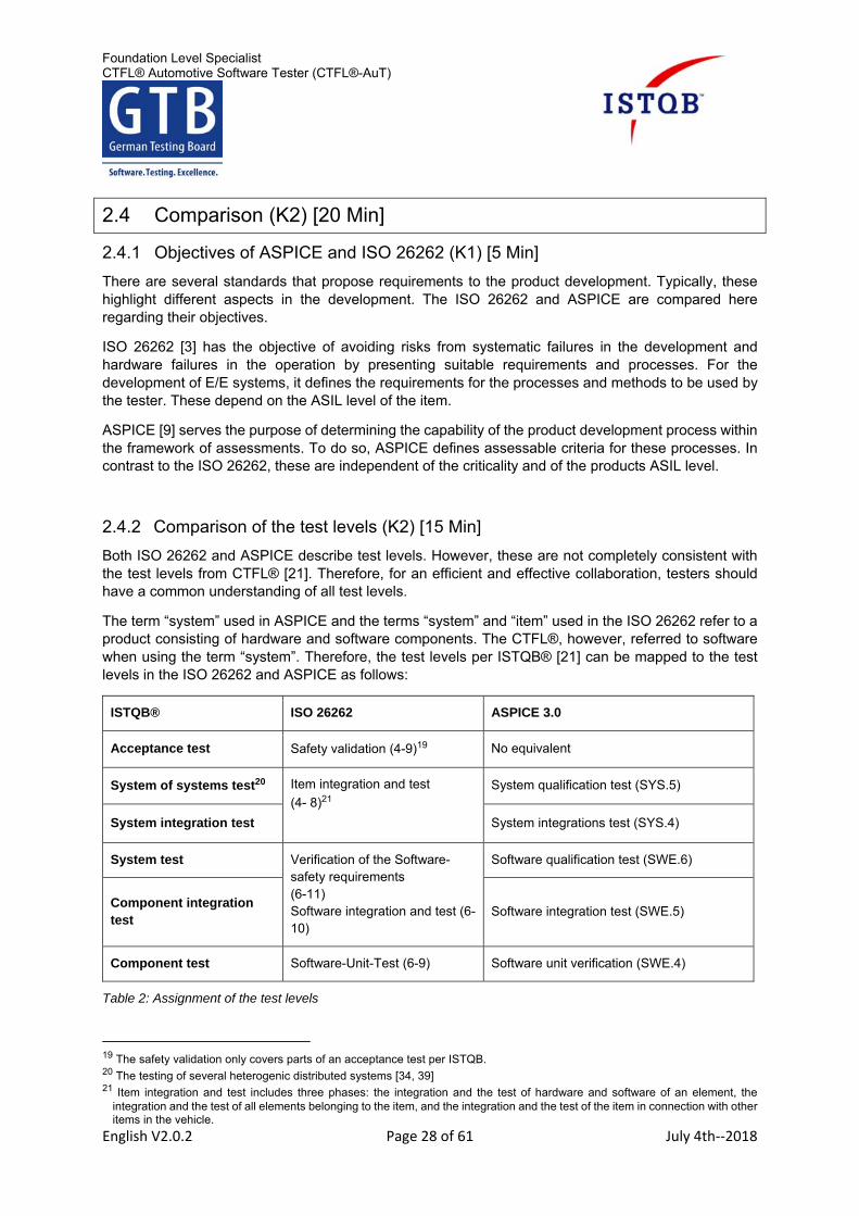
The term “system” used in ASPICE and the terms “system” and “item” used in the ISO 26262 refer to a product consisting of hardware and software components. The CTFL®, however, referred to software when using the term “system”. Therefore, the test levels per ISTQB® [21] can be mapped to the test levels in the ISO 26262 and ASPICE as follows:
ISTQB® ISO 26262 ASPICE 3.0
Acceptance test Safety validation (4-9)19 No equivalent
System of systems test20 Item integration and test
(4- 8)21
System qualification test (SYS.5)
System integration test System integrations test (SYS.4)
System test Verification of the Software- safety requirements (6-11) Software integration and test (6-10)
Software qualification test (SWE.6)
Component integration test
Software integration test (SWE.5)
Component test Software-Unit-Test (6-9) Software unit verification (SWE.4)
Table 2: Assignment of the test levels
19 The safety validation only covers parts of an acceptance test per ISTQB. 20 The testing of several heterogenic distributed systems [34, 39] 21 Item integration and test includes three phases: the integration and the test of hardware and software of an element, the
integration and the test of all elements belonging to the item, and the integration and the test of the item in connection with other items in the vehicle.
Foundation Level Specialist CTFL® Automotive Software Tester (CTFL®-AuT)
English V2.0.2 Page 29 of 61 July 4th‐‐2018
According to ISTQB® CTFL® Core Syllabus ([21], [48]) the test techniques are mostly applicable independently from the test levels. ASPICE also does not generally assign any techniques to test levels. Therefore, both leave the choice to the testers. In the ISO 26262 on the other hand, there are individual method tables for each test level (see chapters 2.2.5 and 2.2.4.2). These provide the tester with recommendations depending on the ASIL level as to which techniques he should use.
Foundation Level Specialist CTFL® Automotive Software Tester (CTFL®-AuT)
English V2.0.2 Page 30 of 61 July 4th‐‐2018
3 Testing in a virtual environment (K3) [160 Min]
Terms
Model in the Loop (MiL), Software in the Loop (SiL), Hardware in the Loop (HiL), Open-Loop-System, Closed-Loop-System, Environment model (Automotive)
Learning objectives
AUTFL-3.1.1 Recall the purpose/the motivation behind a test environment in the automotive development. (K1)
AUTFL-3.1.2 Recall the general parts of an automotive specific test environment. (K1)
AUTFL-3.1.3 Recall the differences between Closed-Loop systems and Open-Loop systems. (K2)
AUTFL-3.1.4 Recall the essential functions, databases and protocols of an automotive control unit. (K1)
AUTFL-3.2.1.1 Recall the structure of a MiL test environment. (K1)
AUTFL-3.2.1.2 Explain the application area and the boundary conditions of a MiL test environment. (K2)
AUTFL-3.2.2.1 Recall the structure of a SiL test environment. (K1)
AUTFL-3.2.2.2 Recall the application areas and the boundary conditions of an SiL test environment. (K1)
AUTFL-3.2.3.1 Recall the structure of a HiL test environment. (K1)
AUTFL-3.2.3.2 Explain the application areas and the boundary conditions of a HiL test environment. (K2)
AUTFL-3.2.4.1 Summarize the advantages and disadvantages for the testing with help of criteria of the XiL test environments (MiL, SiL and HiL). (K2)
AUTFL-3.2.4.2 Apply criteria for the assignment of a given extent of the test to one or more test environments. (K3)
AUTFL-3.2.4.3 Classify the three XiL test environments (MiL, SiL, HiL) in the V-model. (K1)
3.1 Test environment in general (K2) [30 Min]
3.1.1 Motivation for a test environment in the automotive development (K1) [5 Min]
The tester faces special challenges. On one hand, he is expected to start testing as early as possible to find defects early in the development process. On the other hand, he needs a realistic environment to test the system and to find the defects that would appear in the completed product. The tester can solve this conflict by using suitable test environments that match the different development phases. In doing so, the tester can implement and execute his individual test tasks before the completely produced or developed electronic control unit (ECU) is available. By using different test environments, he can simulate situations and execute test cases that would be difficult to reproduce in the actual vehicle, for example, short circuits and open circuits in wiring harnesses or overload in network communications. [24]
Foundation Level Specialist CTFL® Automotive Software Tester (CTFL®-AuT)
English V2.0.2 Page 31 of 61 July 4th‐‐2018
3.1.2 General parts of a test environment (K1) [5 Min]
For the tester to be able to perform his activities, he needs a test environment in which the missing parts are simulated. This environment helps the tester to stimulate the inputs of the test item and to observe their outputs, also called ‘point of control’ (PoC) and ‘point of observation’ (PoO). According to ISO/IEC/IEEE 29119, a test environment consists of the following parts:
Hardware of the test environment (computer, if necessary also a real time capable computer, test bench, development kit, …)
Software of the test environment (operating system, simulation software, environment models) Facilities of communication (access to networks, data logger) Tools (oscilloscope, measuring tools) Laboratory (protection from electromagnetic radiation and noise)
An important part of the test environment is the environment model. Models are an important part of the virtual test environment. They represent aspects of the real world such as the combustion engine, transmissions, vehicle sensors and electronic control units or even the driver or the road conditions. The test environment also has different access points. The tester can use these to measure and observe the test item [25].
3.1.3 Differences between Closed-Loop and Open-Loop (K2) [15 Min]
The test environment is used to stimulate the input interfaces of the device under test and monitor its outputs through the output interfaces. Afterwards, the behaviour at the output interfaces is analysed. In a successful test, the observed behaviour corresponds to the expected output.
Generally, there are two types of control systems, closed loop and open loop. The difference relies on the way the electronic control unit reacts to its environment and this generates different simulation requirements for the virtual test environment.
3.1.3.1 Open-Loop-System
In an open-loop system, the outputs of the system have no relation to the inputs. The system is open ended and there is no feedback. In this case the inputs of the test item are directly defined by the tester in the test procedure.
The application case for Open-Loop and Closed-Loop systems depends strongly on the operating principle of the test item. If the test item has a reactive behaviour or if it mirrors a state machine, an Open-Loop system is preferred. In the interior and chassis electronic there are many examples of Open-Loop systems (see lights and switches).
3.1.3.2 Closed-Loop-System
The stimulation in a Closed-Loop system (also known as in-the-Loop) takes the output of the test item into consideration. This is done via an environment model, which collects the outputs and forwards them directly or indirectly to the input of the test item. Therefore, a control loop is created in the test environment.
For the testing of controllers, the Closed-Loop systems are used more often. Using this, the tester can test complex functions such as motor and gear controls as well as driver assist systems such as the anti-lock braking system (ABS®) or the vehicle dynamics control (ESP®). [26, 27]
Foundation Level Specialist CTFL® Automotive Software Tester (CTFL®-AuT)
English V2.0.2 Page 32 of 61 July 4th‐‐2018
3.1.4 Essential interfaces, databases and communication protocols of a electronic control unit (K1) [5 Min]
A control unit in the automotive environment is an embedded system, which consists of hardware and software. The electronic control unit receives different analogue and digital inputs, which constantly collect environmental data in the form of voltage, current and temperature. Moreover, communication bus systems provide further information to the control unit. Which comes from sensors or other electronic control units, which either collect and process the information themselves or generates them. The test object manages the data in the memory to process the output action, information or data. The generated outputs are also carried out via analogue and digital output pins, bus systems or diagnosis interfaces.
The databases are data warehouses and define the input and output signals of the control unit. These data also include descriptions, units and conversion formulas of the signals.
The communication protocols describe the data exchange via the corresponding physical interfaces. These protocols define which voltage or bit sequence represents which value of the signal.
The choice of the database and the communication protocol depends on the function of the electronic control unit. For example, to access diagnosis functions in the control unit, the tester needs the information about the used database (for example ASAM MCD2 D; also “Open Diagnostic Data Exchange”) and the communication protocol (“Unified Diagnostic Services” per ISO 14229). Further automotive specific databases are defined for example in the ASAM standard [27, 28].
Foundation Level Specialist CTFL® Automotive Software Tester (CTFL®-AuT)
English V2.0.2 Page 33 of 61 July 4th‐‐2018
3.2 Testing in XiL test environments (K3) [130 Min]
In the automotive industry, the following types of XiL-test environments are used:
Model in the Loop (MiL), Software in the Loop (SiL), Processor in the Loop22 (PiL), Hardware in the Loop (HiL) and Vehicle in the Loop23 (ViL)
Here, the tester should become familiar with the test environments (MiL, SiL and HiL) and understand them. The following paragraphs look deeper into the structure and the application areas of the different test environments. XiL in this sense stands as generic term for the different test environments.
3.2.1 Model in the Loop (MiL) (K2) [20 Min]
3.2.1.1 Structure of a MiL test environment
In a MiL test environment, the test item is available as a model. This model is executable but not compiled for a special hardware. Such models are modelled by the developers using special modelling tools. For the tester to be able to execute and test those models, he needs a test environment. This is mostly implemented in the same development environment as the test item itself. This test environment can additionally contain an environment model. The tester can stimulate and observe the test item via access points. The access points can be placed arbitrarily in the model of the test item and also in the environment model. The model of the test item is connected to the environment model and can easily be implemented and used as a Closed-Loop system.
3.2.1.2 Application areas and boundary conditions of a MiL test environment
With a MiL test environment, the tester is capable of testing the functional system design. During the development (following the general V-model) the tester can also test single components up to an entire system. To execute the test, the tester needs a computer and the corresponding simulation software including the environment model. The environment model becomes more complex as the scope of functions of the test item increases. The aspects of reality and environmental factors are very complex. The execution times for the models also increases disproportionately. Therefore, the effort to implement a MiL test environment is no longer worthwhile from a certain phase of the development.24
By using a MiL test environment, the tester can test the functionality of models over all development levels at the early phase of development (left side of the V-Model). But it is not common to enable the environment model to simulate bus or diagnosis functions or physical behaviour (such as cable breaks or shorts). These tasks can be carried out more easily and at less cost with other test environments.
In a MiL test environment, it must be appreciated that the test execution does not take place in real time. As all components are available as a model, the test execution runs in simulation time. The more complex a system, the more execution time or power the computer needs to provide all necessary information. The duration of the simulation in smaller systems is shorter than the execution in real time. However, a big advantage is that the tester can pause the simulation at any time to execute detailed analysis and assessments.
22 This test environment is not considered in this syllabus and is purely informative. 23 This test environment is not considered in this syllabus and is purely informative. 24 This is also valid for all other XiL environments.
Foundation Level Specialist CTFL® Automotive Software Tester (CTFL®-AuT)
English V2.0.2 Page 34 of 61 July 4th‐‐2018
3.2.2 Software in the Loop (SiL) (K1) [10 Min]
3.2.2.1 Structure of a SiL test environment
The test item is compiled for a specific SiL test environment. This means the source code has been compiled with a software tool for a certain computer architecture. This machine code is (only) readable by the test environment as it consists of binary data sets. For the test environment to be able to access signals, a wrapper is necessary. A wrapper is additional software that creates a specific access interface for the machine code. Therefore, the tester can stimulate software signals and observe them. The wrapper defines the access points to the test item but does not perform its functional tasks.
For the simulation, an environment model is needed. The test item is connected to the test environment with the help of the wrapper. The test execution is carried out on a computer without special hardware. The tester needs a software tool that is capable of creating a wrapper for the test item with access points to the test environment.
3.2.2.2 Application areas and boundary conditions of a SiL test environment
If the developer generates source code based on a model, the real behavior of the software can be different to the expected behavior. This can be caused by different data types in the model (mostly floating point) and in the compiled software code (mostly fix point) but also by different memory spaces. These aberrations in the expected behavior can be tested for the first time in a SiL test environment. The tester can use techniques like back-to-back-Testing (see also 4.2.2) to compare the behavior.
The tester runs the tests, analogous to the MiL test environment, in simulation time. Depending on the calculation technique and the complexity of the environment model, this simulation time can be shorter or longer than in real time. The tester can pause the execution at any time to execute detailed analysis and assessments. Functional, interface and regression tests are very common test types that can be evaluated in a SiL test environment. On the other hand, performance and reliability tests are unusual. These Software characteristics are mostly affected by the target hardware.
3.2.3 Hardware in the Loop (HiL) (K2) [20 Min]
3.2.3.1 Structure of a HiL test environment
If the test item is available as a prototype or if it is already completely developed, the tester can use a HiL test environment to execute tests. The typical parts of a HiL test environment are:
A power supply to set different supply voltages A real time capable computer for the environment model to run on Several real parts that are not implemented in the environment model A signal processing of signal type and signal amplitude A fault insertion unit (FIU, see also 4.2.3) for the simulation of cable breaks and shorts A breakout box as an additional access interface in the cable harness A remaining bus simulation for the simulation of the non-existing bus participants
Foundation Level Specialist CTFL® Automotive Software Tester (CTFL®-AuT)
English V2.0.2 Page 35 of 61 July 4th‐‐2018
3.2.3.2 Application areas and boundary conditions of a HiL test environment
The access points in a HiL test environment are diverse. The tester must be aware that using the wrong access points to the test item can render the test results useless. Knowing the different access points and their connections in the HiL test environment enables effective tests to be implemented, executed and assessed.
The HiL test environment is more complex than the previously mentioned test environments (MiL and SiL) due to its several parts. The tester must master this complexity to address his test tasks. The HiL test environment can be used for component tests, integration tests and system tests. The objective is, among other things, to find functional and non-functional defects in the software and hardware.
With the help of HiL test environments, different test levels can be analysed. If the test item is a single electronic control unit (ECU), it is called component25 HiL. If the test item is a combination of several electronic control units, it is called system HiL. The tester uses the component HiL to test functions of the control unit. In the system HiL, the focus is on the testing of the data exchange between the electronic control units and on the system test of the entire system.
In contrast to the previously mentioned test environments (MiL and SiL) the simulation time in a HiL test environment always runs in real time. The reason for this is that the software is running on a real hardware. Pausing or stopping is no longer possible in this test environment. Therefore, the test environment includes a real time capable computer that is able to collect and serve all relevant signals within a predetermined period of time.
3.2.4 Comparison of the XiL test environments (K3) [80 Min]
3.2.4.1 Advantages and disadvantages oftesting in the XiL test environments
The tester understand the attributes of the different test environments. In doing so, he can understand and assess the advantages and disadvantages of testing in each environment. The criteria are shown in table 3.
Criteria MiL test environment SiL test environment HiL test environment
Closeness to reality
Low Low to medium High
Reality is simulated, many characteristics are abstracted, the focus is on the structures and logic
Compiled real software can be executed (without Hardware)
Integrated system, able to run
Time and effort of debugging
Low Medium High
Defects found in the model of the test item (model adjustment)
Defects found in programmed software (software adjustment)
Defects found in system level (system adjustment)
Effort for implementation and maintenance
Low Medium High
Create environment model
Create environment model and wrapper
Create environment model and wire the hardware components
25 The term „component“ is in this case used for an electronic control unit (ECU) in the context of a E/E-system.
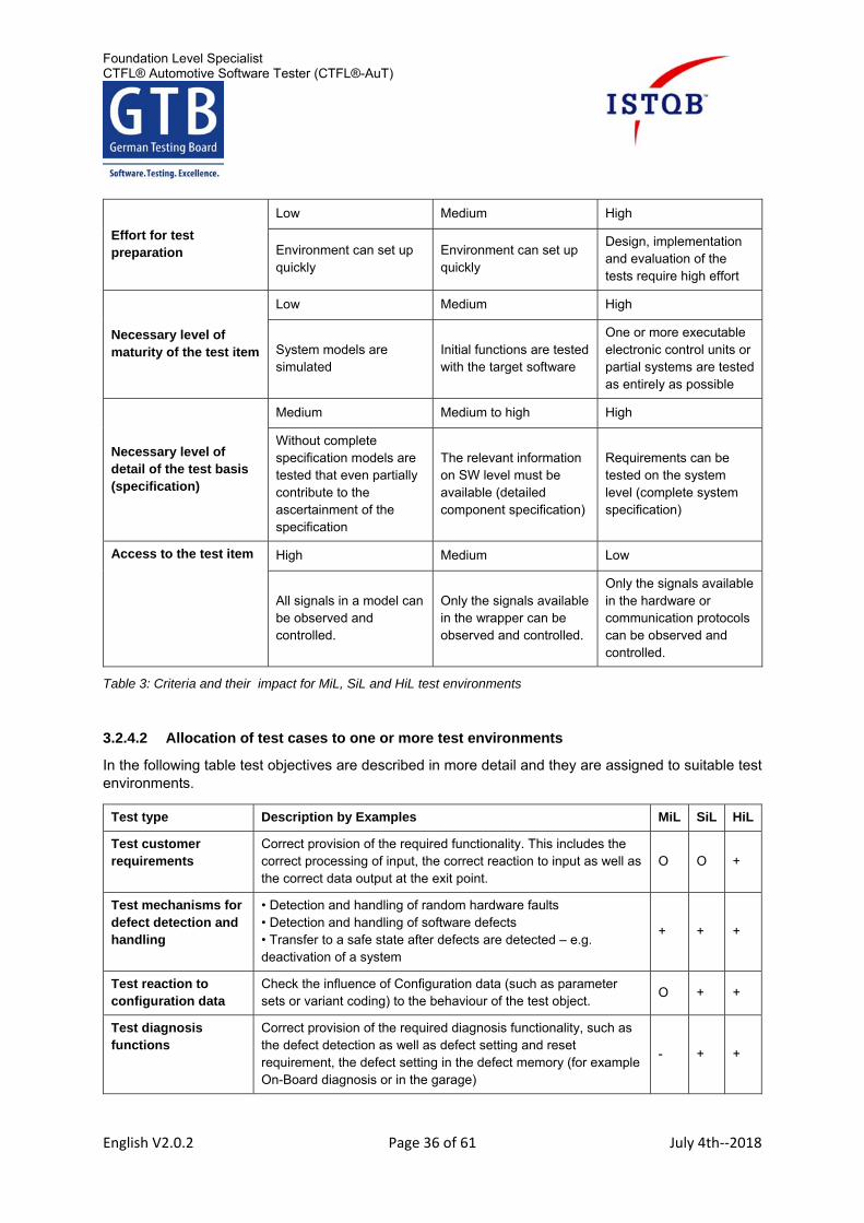
Foundation Level Specialist CTFL® Automotive Software Tester (CTFL®-AuT)
English V2.0.2 Page 36 of 61 July 4th‐‐2018
Effort for test preparation
Low Medium High
Environment can set up quickly
Environment can set up quickly
Design, implementation and evaluation of the tests require high effort
Necessary level of maturity of the test item
Low Medium High
System models are simulated
Initial functions are tested with the target software
One or more executable electronic control units or partial systems are tested as entirely as possible
Necessary level of detail of the test basis (specification)
Medium Medium to high High
Without complete specification models are tested that even partially contribute to the ascertainment of the specification
The relevant information on SW level must be available (detailed component specification)
Requirements can be tested on the system level (complete system specification)
Access to the test item High Medium Low
All signals in a model can be observed and controlled.
Only the signals available in the wrapper can be observed and controlled.
Only the signals available in the hardware or communication protocols can be observed and controlled.
Table 3: Criteria and their impact for MiL, SiL and HiL test environments
3.2.4.2 Allocation of test cases to one or more test environments
In the following table test objectives are described in more detail and they are assigned to suitable test environments.
Test type Description by Examples MiL SiL HiL
Test customer requirements
Correct provision of the required functionality. This includes the correct processing of input, the correct reaction to input as well as the correct data output at the exit point.
O O +
Test mechanisms for defect detection and handling
• Detection and handling of random hardware faults • Detection and handling of software defects • Transfer to a safe state after defects are detected – e.g. deactivation of a system
+ + +
Test reaction to configuration data
Check the influence of Configuration data (such as parameter sets or variant coding) to the behaviour of the test object.
O + +
Test diagnosis functions
Correct provision of the required diagnosis functionality, such as the defect detection as well as defect setting and reset requirement, the defect setting in the defect memory (for example On-Board diagnosis or in the garage)
- + +
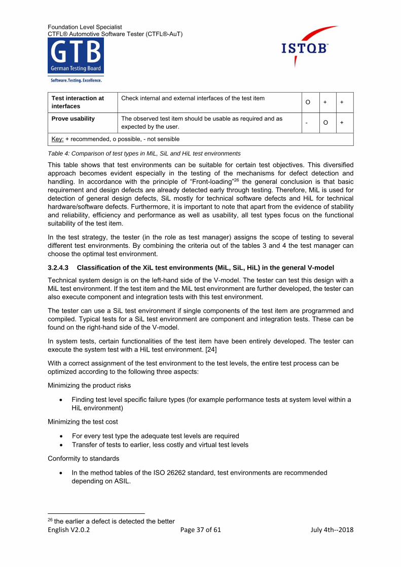
Foundation Level Specialist CTFL® Automotive Software Tester (CTFL®-AuT)
English V2.0.2 Page 37 of 61 July 4th‐‐2018
Test interaction at interfaces
Check internal and external interfaces of the test item O + +
Prove usability The observed test item should be usable as required and as expected by the user.
- O +
Key: + recommended, o possible, - not sensible
Table 4: Comparison of test types in MiL, SiL and HiL test environments
This table shows that test environments can be suitable for certain test objectives. This diversified approach becomes evident especially in the testing of the mechanisms for defect detection and handling. In accordance with the principle of “Front-loading”26 the general conclusion is that basic requirement and design defects are already detected early through testing. Therefore, MiL is used for detection of general design defects, SiL mostly for technical software defects and HiL for technical hardware/software defects. Furthermore, it is important to note that apart from the evidence of stability and reliability, efficiency and performance as well as usability, all test types focus on the functional suitability of the test item.
In the test strategy, the tester (in the role as test manager) assigns the scope of testing to several different test environments. By combining the criteria out of the tables 3 and 4 the test manager can choose the optimal test environment.
3.2.4.3 Classification of the XiL test environments (MiL, SiL, HiL) in the general V-model
Technical system design is on the left-hand side of the V-model. The tester can test this design with a MiL test environment. If the test item and the MiL test environment are further developed, the tester can also execute component and integration tests with this test environment.
The tester can use a SiL test environment if single components of the test item are programmed and compiled. Typical tests for a SiL test environment are component and integration tests. These can be found on the right-hand side of the V-model.
In system tests, certain functionalities of the test item have been entirely developed. The tester can execute the system test with a HiL test environment. [24]
With a correct assignment of the test environment to the test levels, the entire test process can be optimized according to the following three aspects:
Minimizing the product risks
Finding test level specific failure types (for example performance tests at system level within a HiL environment)
Minimizing the test cost
For every test type the adequate test levels are required Transfer of tests to earlier, less costly and virtual test levels
Conformity to standards
In the method tables of the ISO 26262 standard, test environments are recommended depending on ASIL.
26 the earlier a defect is detected the better
Foundation Level Specialist CTFL® Automotive Software Tester (CTFL®-AuT)
English V2.0.2 Page 38 of 61 July 4th‐‐2018
4 Automotive-specific static and dynamic test techniques [230 Min]
Terms
Coding standard, back-to-back testing
Learning objectives
Static test techniques
AUTFL-4.1.1 Explain the purpose and requirements of the MISRA-C:2012 guideline with the help of examples. (K2)
AUTFL-4.1.2 Apply a review of requirements using the quality characteristics of the ISO/IEC 29148 standard that are relevant to testers. (K3)
Dynamic test techniques
AUTFL-4.2.1 Create test cases to achieve modified condition/decision testing coverage. (K3)
AUTFL-4.2.2 Explain the use of back-to-back testing by giving examples. (K2)
AUTFL-4.2.3 Explain the principle of fault injection testing by giving examples. (K2)
AUTFL-4.2.4 Recall the principles of requirements-based testing. (K1)
AUTFL-4.2.5 Apply context dependent criteria for the choice of suitable and necessary test design techniques. (K3)
4.1 Static test techniques (K3) [75 Min]
Introduction
Static testing is examining work products of the software development without executing them. This includes evaluation by people (review) and the tool-supported static analysis.
4.1.1 The MISRA-C: 2012 Guidelines (K2) [15 Min]
It is part of the state of the art today that the developer complies with coding guidelines when programming. The ISO 26262 standard also recommends that for safety-relevant software27. Coding standards help to avoid anomalies in the software, which can possibly lead to defects. At the same time, they support the developer in improving the maintainability and portability of his software.
The MISRA-C:2012 Guidelines [15] include guidelines for the programming language C. It defines two types of guidelines:
Rules are in general verifiable by static analytic tools. For example, that the source code does not include nested comments.
Directives are not entirely verifiable by static analytic tools. The reason for that is that they rather refer to details of the development process or documents outside of the software. For example, if the developer has sufficiently documented the implemented behaviour.
27 See also [ISO 26262:2011] Part 9 Table 6
Foundation Level Specialist CTFL® Automotive Software Tester (CTFL®-AuT)
English V2.0.2 Page 39 of 61 July 4th‐‐2018
Each guideline is categorised as one of the following three levels of obligation:
“advisory” guidelines should be followed by the developer if the effort is appropriate. “required” guidelines may only be neglected by the developer if he can conclusively explain it “mandatory” guidelines must be followed by the developer. Exceptions are not allowed.
Organizations can individually intensify the requirement of a rule or directive, but they can never lower it.
4.1.2 Quality characteristics for reviews of requirements (K3) [60 Min]
Specifications are the basis for the development and testing. Therefore, defects in those specifications lead to cost and time intensive follow up activities. This applies especially if the defects are only detected in late development phases such as the acceptance testing or in operation. Reviews are an effective measure to find defects in specifications early and consequently be able to fix them early and at low cost.
During test analysis, the tester must check the specifications for the test item [21]. In doing so, the specifications are especially checked with regards to their suitability as a test basis. Quality characteristics help the tester during the reviews of the specifications to focus his attention and find as many defects as possible. ISO/IEC/IEEE 29148:2011[37] includes quality characteristics for single requirements as well as for groups of requirements.
Requirements characteristics per ISO/IEC/IEEE 29148:2011 relevant for testers
Characteristics for individual requirements respectively for a set of requirements:
Verifiable: Each requirement can be verified by static or dynamic tests. Unambiguous: Each requirement contains clear test conditions. Consistent: Each requirement is consistent in itself and with other requirements. Complete: Each requirement considers all possible cases (also error, abort and exception
scenarios). At the same time, all tables and diagrams used are labelled; abbreviations and terms used are defined.
Traceable: Each requirement is clearly marked (for example by an ID). This allows an impact analysis and the coverage by test cases is transparent.
Bounded (for a set of requirements): It is clearly defined, what is the scope to be developed and therefore tested.
Singular: No requirement can be divided into sensible partial requirements.
As a tool for the review, the tester can for example derive review checklists from the characteristics. These review checklists then include suitable questions for the previously mentioned statements. The tester must answer them to the best of his knowledge and belief. The following list includes an excerpt of possible questions that must be answered for each requirement:
Verifiable: Is the requirement verifiable by static or dynamic tests on the according test level? Explicit: Does the requirement prevent any room for interpretation or is it not build upon
implicit knowledge or experience knowledge? Consistent: Is the requirement consistent in itself and towards other requirements? Singular: Can the requirement not be divided into further partial requirements, e.g. by solving
logical links such as if-then-else constructs within the requirements and separately noting the resulting partial requirements?
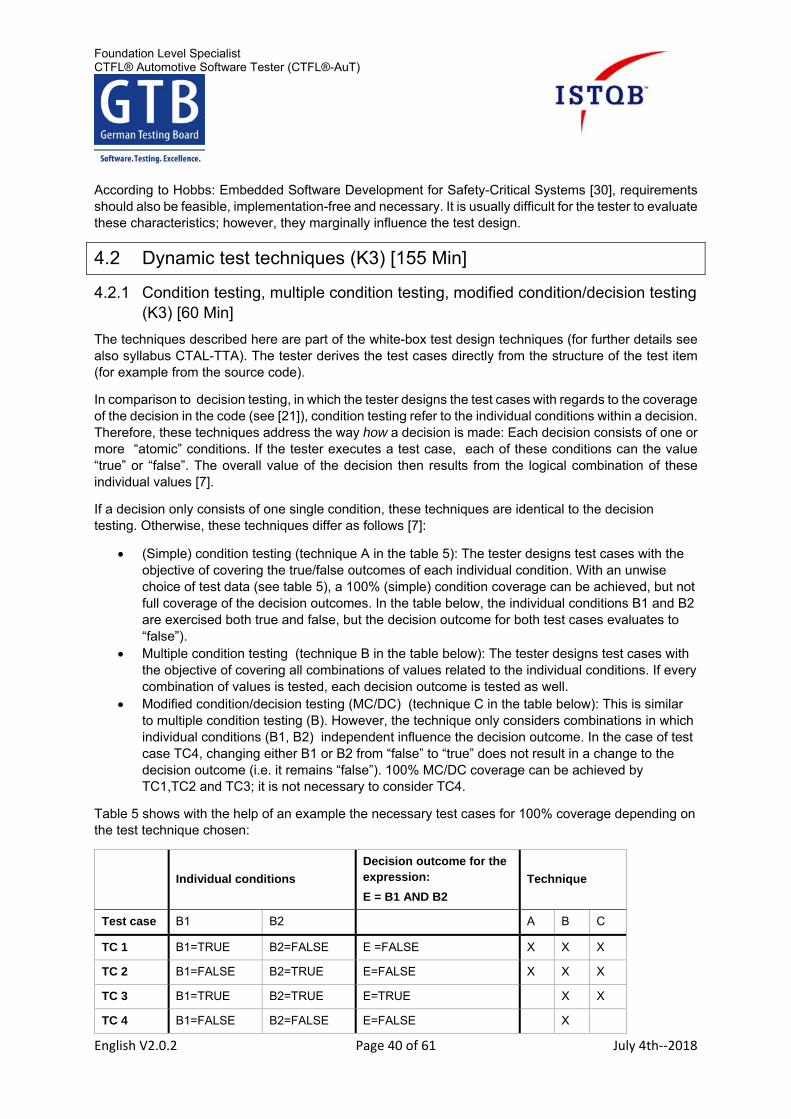
Foundation Level Specialist CTFL® Automotive Software Tester (CTFL®-AuT)
English V2.0.2 Page 40 of 61 July 4th‐‐2018
According to Hobbs: Embedded Software Development for Safety-Critical Systems [30], requirements should also be feasible, implementation-free and necessary. It is usually difficult for the tester to evaluate these characteristics; however, they marginally influence the test design.
4.2 Dynamic test techniques (K3) [155 Min]
4.2.1 Condition testing, multiple condition testing, modified condition/decision testing (K3) [60 Min]
The techniques described here are part of the white-box test design techniques (for further details see also syllabus CTAL-TTA). The tester derives the test cases directly from the structure of the test item (for example from the source code).
In comparison to decision testing, in which the tester designs the test cases with regards to the coverage of the decision in the code (see [21]), condition testing refer to the individual conditions within a decision. Therefore, these techniques address the way how a decision is made: Each decision consists of one or more “atomic” conditions. If the tester executes a test case, each of these conditions can the value “true” or “false”. The overall value of the decision then results from the logical combination of these individual values [7].
If a decision only consists of one single condition, these techniques are identical to the decision testing. Otherwise, these techniques differ as follows [7]:
(Simple) condition testing (technique A in the table 5): The tester designs test cases with the objective of covering the true/false outcomes of each individual condition. With an unwise choice of test data (see table 5), a 100% (simple) condition coverage can be achieved, but not full coverage of the decision outcomes. In the table below, the individual conditions B1 and B2 are exercised both true and false, but the decision outcome for both test cases evaluates to “false”).
Multiple condition testing (technique B in the table below): The tester designs test cases with the objective of covering all combinations of values related to the individual conditions. If every combination of values is tested, each decision outcome is tested as well.
Modified condition/decision testing (MC/DC) (technique C in the table below): This is similar to multiple condition testing (B). However, the technique only considers combinations in which individual conditions (B1, B2) independent influence the decision outcome. In the case of test case TC4, changing either B1 or B2 from “false” to “true” does not result in a change to the decision outcome (i.e. it remains “false”). 100% MC/DC coverage can be achieved by TC1,TC2 and TC3; it is not necessary to consider TC4.
Table 5 shows with the help of an example the necessary test cases for 100% coverage depending on the test technique chosen:
Individual conditions
Decision outcome for the expression:
E = B1 AND B2
Technique
Test case B1 B2 A B C
TC 1 B1=TRUE B2=FALSE E =FALSE X X X
TC 2 B1=FALSE B2=TRUE E=FALSE X X X
TC 3 B1=TRUE B2=TRUE E=TRUE X X
TC 4 B1=FALSE B2=FALSE E=FALSE X
Foundation Level Specialist CTFL® Automotive Software Tester (CTFL®-AuT)
English V2.0.2 Page 41 of 61 July 4th‐‐2018
Table 5: Comparison of the techniques condition testing (A), multiple condition testing (B) and modified condition/decision testing (MC/DC test) (C)
The example shows the limits of the techniques: In case of the (simple) condition testing (A), despite a condition coverage of 100%, the tester takes the risk of only covering one decision outcome. A better choice of the test cases would correct this (in the example TC 3 and TC 4).
With the use of the multiple condition testing (B) the tester can cover all possible inputs and outputs. However, the number of tests to be executed is the highest for this technique.
By using the modified condition/decision testing (C), the tester can achieve a complete coverage of all single conditions and all decisions with a fewer number of tests compared to multiple condition testing.
4.2.2 Back-to-Back-Testing (K2) [15 Min]
Back-to-back testing (also: comparative test [32]) is more an approach to testing than a test (design) technique. It compares two or more variants of a test item. To do that, the tester executes the same test case on all variants and compares the results. If the results are identical, the test has been passed. If the results differ, the cause of the detected difference is analysed.
The test items must be based on the same requirements from the content point of view. Only in this way can they show a comparable behaviour. The requirements do not serve as a test basis for the test design. On the contrary, the back-to-back test is expected to show the slightest unintended differences between the test items or the test environment. This test does therefore not replace the requirement-based test.
In the simplest case, the test items of a back-to-back test are different versions of the same software. In this case, for example an earlier version of the test item serves as test oracle for the back-to-back-test(similar to a regression test) [33]. Another alternative is the comparison of an executable model with the (manually or automatically) generated code [32]. In this case, it is a form of model based testing, in which the executable model also serves as test oracle [34]. This technique is therefore very suitable for automated test design. Here, the tester derives not only the expected result from the model, but also automated test cases.
4.2.3 Fault injection testing (K2) [15 Min]
Fault injection testing is more an approach for robustness testing than a special test (design) technique. Programming techniques such as the error handling serve the purpose of making the system react to internal and external defects in a robust and safe way. To test these techniques, the tester can selectively insert defects into the system at the following points [34]:
Defects in external components: If the system for example has to safely detect implausible values from sensors.
Defects in interfaces: If for example the function of the system must not be harmed by short circuits or lost messages.
Defects in the software: If the system should detect and handle internal defects.
In the classic fault injection, the tester inserts a defect by manipulating the real component.
External defects (also interface defects) can be simulated by the tester y at run-time. The fault injection usually takes place in a HiL test environment. Here, a fault insertion unit (FIU) [35] serves as a driver for physical defects. Among these defects rank in particular short circuits and open circuits. The simulation of software based interface defects can often already be done in a SiL test environment.
Defects in the software can often only be inserted in the development environment for example via debugger or XCP. The execution is therefore in practice often very time intensive.
Foundation Level Specialist CTFL® Automotive Software Tester (CTFL®-AuT)
English V2.0.2 Page 42 of 61 July 4th‐‐2018
4.2.4 Requirements-based testing (K1) [5 Min]
Requirements-based testing is an approach (a practice) for testing [22] and less a test (design) technique. The approach aims at covering the requirements with test cases. Therefore, the tester decides whether the test item meets the requirements.
In this approach, the tester analyses the requirements, derives test conditions, designs test cases and executes them. Based on the analysis of the test results, he refines the tests. In doing so, he can also create further test cases. In addition, the tester applies further test practices (such as experience based testing). Therefore, he can reduce the risk of defects for example by regression tests in form of exploratory tests.
If the requirements are incomplete or inconsistent, the tests designed on that basis suffer from the same problems. On the other hand, the tester may not be able to test all the requirements if they are very detailed. Here, a prioritization of the test cases is mandatory. [3]
4.2.5 Context-dependent selection of test techniques (K3) [60 Min]
The ISO 26262 standard (Volume 6) suggests that the tester applies test design techniques (see chapter 2.2) depending on the ASIL level. These include among others the techniques mentioned in CTFL® and previously in chapter 4.2:
Requirements-based testing Equivalence partitioning Boundary value analysis Statement testing Decision testing Modified condition/decision testing Error guessing Fault injection Back-to-back testing
However, the decision on what technique to use depends on the following factors, among others:
State of the Art
Does the technique represent the current state of the art for this purpose? Here, standards like the ISO/IEC/IEEE 29119 and the ISO 26262 help. The ISO 26262 standard even suggests applicable techniques depending on the ASIL level. Deviations from the recommendations of the standard are discussed in chapter 2.2 regarding ISO 26262.
Test basis
Does the test basis provide suitable test conditions for the technique? For example, the tester can only form equivalence classes if the test basis includes parameter or variables. He must be able to group their values into reasonable equivalence classes. Similar conditions apply to boundary values. He can only test those if the value range is defined in a linear way.
Risk-based testing
Risk-based testing means the identification of product risks and the consideration of the risk level for the selection of the techniques. For example, the test of a boundary value only makes sense if there is a risk of boundary violations occurring and if the impact of such violations constitutes a risk.
Test level
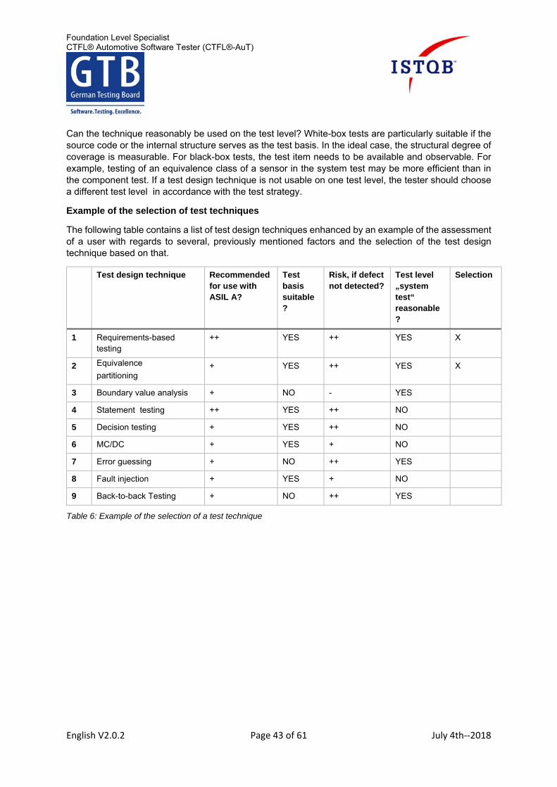
Foundation Level Specialist CTFL® Automotive Software Tester (CTFL®-AuT)
English V2.0.2 Page 43 of 61 July 4th‐‐2018
Can the technique reasonably be used on the test level? White-box tests are particularly suitable if the source code or the internal structure serves as the test basis. In the ideal case, the structural degree of coverage is measurable. For black-box tests, the test item needs to be available and observable. For example, testing of an equivalence class of a sensor in the system test may be more efficient than in the component test. If a test design technique is not usable on one test level, the tester should choose a different test level in accordance with the test strategy.
Example of the selection of test techniques
The following table contains a list of test design techniques enhanced by an example of the assessment of a user with regards to several, previously mentioned factors and the selection of the test design technique based on that.
Test design technique Recommended for use with ASIL A?
Test basis suitable?
Risk, if defect not detected?
Test level „system test“ reasonable?
Selection
1 Requirements-based testing
++ YES ++ YES X
2 Equivalence
partitioning + YES ++ YES X
3 Boundary value analysis + NO - YES
4 Statement testing ++ YES ++ NO
5 Decision testing + YES ++ NO
6 MC/DC + YES + NO
7 Error guessing + NO ++ YES
8 Fault injection + YES + NO
9 Back-to-back Testing + NO ++ YES
Table 6: Example of the selection of a test technique
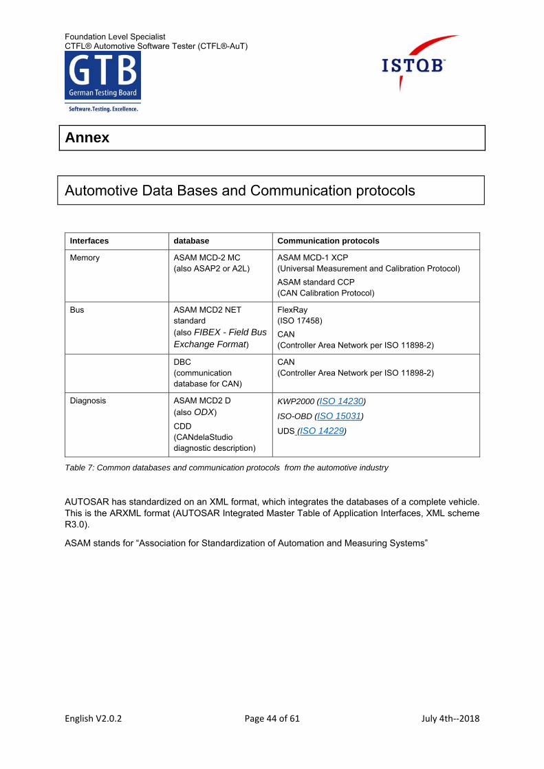
Foundation Level Specialist CTFL® Automotive Software Tester (CTFL®-AuT)
English V2.0.2 Page 44 of 61 July 4th‐‐2018
Annex
Automotive Data Bases and Communication protocols
Interfaces database Communication protocols
Memory ASAM MCD-2 MC (also ASAP2 or A2L)
ASAM MCD-1 XCP (Universal Measurement and Calibration Protocol)
ASAM standard CCP (CAN Calibration Protocol)
Bus ASAM MCD2 NET standard
(also FIBEX - Field Bus Exchange Format)
FlexRay (ISO 17458)
CAN (Controller Area Network per ISO 11898-2)
DBC (communication database for CAN)
CAN (Controller Area Network per ISO 11898-2)
Diagnosis ASAM MCD2 D
(also ODX)
CDD (CANdelaStudio diagnostic description)
KWP2000 (ISO 14230)
ISO-OBD (ISO 15031)
UDS (ISO 14229)
Table 7: Common databases and communication protocols from the automotive industry
AUTOSAR has standardized on an XML format, which integrates the databases of a complete vehicle. This is the ARXML format (AUTOSAR Integrated Master Table of Application Interfaces, XML scheme R3.0).
ASAM stands for “Association for Standardization of Automation and Measuring Systems”
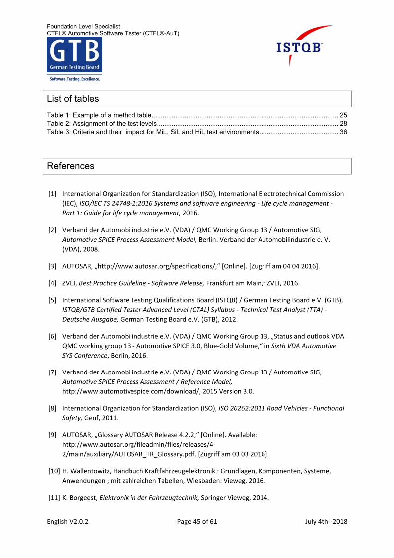
Foundation Level Specialist CTFL® Automotive Software Tester (CTFL®-AuT)
English V2.0.2 Page 45 of 61 July 4th‐‐2018
List of tables
Table 1: Example of a method table ...................................................................................................... 25 Table 2: Assignment of the test levels ................................................................................................... 28 Table 3: Criteria and their impact for MiL, SiL and HiL test environments ........................................... 36
References
[1] International Organization for Standardization (ISO), International Electrotechnical Commission
(IEC), ISO/IEC TS 24748‐1:2016 Systems and software engineering ‐ Life cycle management ‐
Part 1: Guide for life cycle management, 2016.
[2] Verband der Automobilindustrie e.V. (VDA) / QMC Working Group 13 / Automotive SIG,
Automotive SPICE Process Assessment Model, Berlin: Verband der Automobilindustrie e. V.
(VDA), 2008.
[3] AUTOSAR, „http://www.autosar.org/specifications/,“ [Online]. [Zugriff am 04 04 2016].
[4] ZVEI, Best Practice Guideline ‐ Software Release, Frankfurt am Main,: ZVEI, 2016.
[5] International Software Testing Qualifications Board (ISTQB) / German Testing Board e.V. (GTB),
ISTQB/GTB Certified Tester Advanced Level (CTAL) Syllabus ‐ Technical Test Analyst (TTA) ‐
Deutsche Ausgabe, German Testing Board e.V. (GTB), 2012.
[6] Verband der Automobilindustrie e.V. (VDA) / QMC Working Group 13, „Status and outlook VDA
QMC working group 13 ‐ Automotive SPICE 3.0, Blue‐Gold Volume,“ in Sixth VDA Automotive
SYS Conference, Berlin, 2016.
[7] Verband der Automobilindustrie e.V. (VDA) / QMC Working Group 13 / Automotive SIG,
Automotive SPICE Process Assessment / Reference Model,
http://www.automotivespice.com/download/, 2015 Version 3.0.
[8] International Organization for Standardization (ISO), ISO 26262:2011 Road Vehicles ‐ Functional
Safety, Genf, 2011.
[9] AUTOSAR, „Glossary AUTOSAR Release 4.2.2,“ [Online]. Available:
http://www.autosar.org/fileadmin/files/releases/4‐
2/main/auxiliary/AUTOSAR_TR_Glossary.pdf. [Zugriff am 03 03 2016].
[10] H. Wallentowitz, Handbuch Kraftfahrzeugelektronik : Grundlagen, Komponenten, Systeme,
Anwendungen ; mit zahlreichen Tabellen, Wiesbaden: Vieweg, 2016.
[11] K. Borgeest, Elektronik in der Fahrzeugtechnik, Springer Vieweg, 2014.
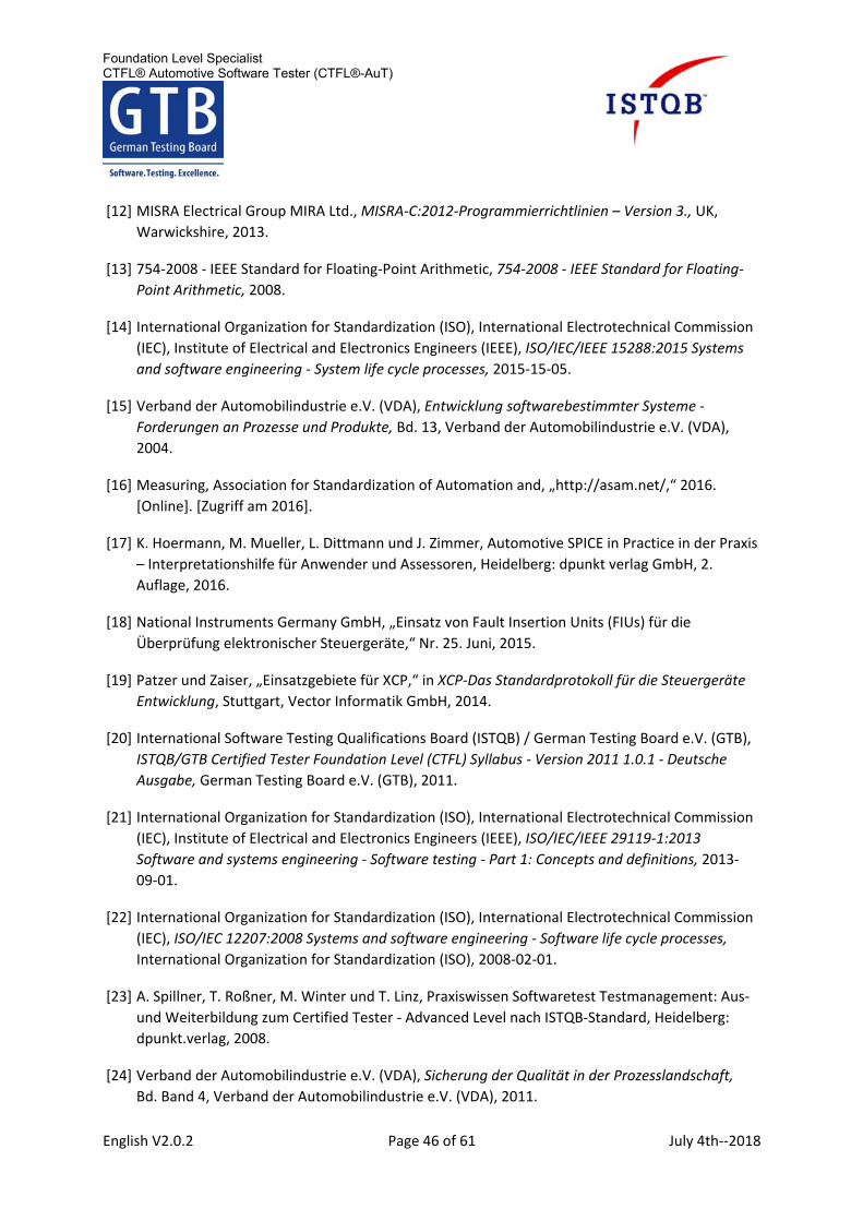
Foundation Level Specialist CTFL® Automotive Software Tester (CTFL®-AuT)
English V2.0.2 Page 46 of 61 July 4th‐‐2018
[12] MISRA Electrical Group MIRA Ltd., MISRA‐C:2012‐Programmierrichtlinien – Version 3., UK,
Warwickshire, 2013.
[13] 754‐2008 ‐ IEEE Standard for Floating‐Point Arithmetic, 754‐2008 ‐ IEEE Standard for Floating‐
Point Arithmetic, 2008.
[14] International Organization for Standardization (ISO), International Electrotechnical Commission
(IEC), Institute of Electrical and Electronics Engineers (IEEE), ISO/IEC/IEEE 15288:2015 Systems
and software engineering ‐ System life cycle processes, 2015‐15‐05.
[15] Verband der Automobilindustrie e.V. (VDA), Entwicklung softwarebestimmter Systeme ‐
Forderungen an Prozesse und Produkte, Bd. 13, Verband der Automobilindustrie e.V. (VDA),
2004.
[16] Measuring, Association for Standardization of Automation and, „http://asam.net/,“ 2016.
[Online]. [Zugriff am 2016].
[17] K. Hoermann, M. Mueller, L. Dittmann und J. Zimmer, Automotive SPICE in Practice in der Praxis
– Interpretationshilfe für Anwender und Assessoren, Heidelberg: dpunkt verlag GmbH, 2.
Auflage, 2016.
[18] National Instruments Germany GmbH, „Einsatz von Fault Insertion Units (FIUs) für die
Überprüfung elektronischer Steuergeräte,“ Nr. 25. Juni, 2015.
[19] Patzer und Zaiser, „Einsatzgebiete für XCP,“ in XCP‐Das Standardprotokoll für die Steuergeräte
Entwicklung, Stuttgart, Vector Informatik GmbH, 2014.
[20] International Software Testing Qualifications Board (ISTQB) / German Testing Board e.V. (GTB),
ISTQB/GTB Certified Tester Foundation Level (CTFL) Syllabus ‐ Version 2011 1.0.1 ‐ Deutsche
Ausgabe, German Testing Board e.V. (GTB), 2011.
[21] International Organization for Standardization (ISO), International Electrotechnical Commission
(IEC), Institute of Electrical and Electronics Engineers (IEEE), ISO/IEC/IEEE 29119‐1:2013
Software and systems engineering ‐ Software testing ‐ Part 1: Concepts and definitions, 2013‐
09‐01.
[22] International Organization for Standardization (ISO), International Electrotechnical Commission
(IEC), ISO/IEC 12207:2008 Systems and software engineering ‐ Software life cycle processes,
International Organization for Standardization (ISO), 2008‐02‐01.
[23] A. Spillner, T. Roßner, M. Winter und T. Linz, Praxiswissen Softwaretest Testmanagement: Aus‐
und Weiterbildung zum Certified Tester ‐ Advanced Level nach ISTQB‐Standard, Heidelberg:
dpunkt.verlag, 2008.
[24] Verband der Automobilindustrie e.V. (VDA), Sicherung der Qualität in der Prozesslandschaft,
Bd. Band 4, Verband der Automobilindustrie e.V. (VDA), 2011.
Foundation Level Specialist CTFL® Automotive Software Tester (CTFL®-AuT)
English V2.0.2 Page 47 of 61 July 4th‐‐2018
[25] dpa, „www.motor‐talk.de,“ 24 02 2015. [Online]. Available: http://www.motor‐
talk.de/news/die‐zahl‐der‐modelle‐waechst‐der‐absatz‐nicht‐t5219608.html. [Zugriff am 12 12
2016].
[26] AUTOSAR, „Requirements on Acceptance Test AUTOSAR TC Release 1.1.0,“ [Online]. Available:
http://www.autosar.org/fileadmin/files/standards/tests/tc‐1‐
1/general_auxiliary/AUTOSAR_ATR_Requirements.pdf. [Zugriff am 2016 12 12].
[27] R. Schönfeld, Regelungen und Steuerungen in der Elektrotechnik, Verlag Technik GmbH, 1993.
[28] AUTOSAR, „Project Objectives AUTOSAR Release 4.2.1,“ [Online]. Available:
http://www.autosar.org/fileadmin/files/releases/4‐
2/main/auxiliary/AUTOSAR_RS_ProjectObjectives.pdf. [Zugriff am 03 03 2016].
[29] AUTOSAR, „Main Requirements AUTOSAR Release 4.2.1,“ [Online]. Available:
http://www.autosar.org/fileadmin/files/releases/4‐2/main/auxiliary/AUTOSAR_RS_Main.pdf.
[Zugriff am 03 03 2016].
[30] G. Baumann, „Was verstehen wir unter Test? Abstraktionsebenen, Begriffe und Definitionen,“
FKFS 1. AutoTest; Fachkonferenz zum Thema Test und Diagnose in der Automobilentwicklung.,
Stuttgart, 2006.
[31] C. Hobbs, Embedded Software Development for Safety‐Critical Systems, Taylor & Francis
Group, 2016.
[32] AUTOSAR, „AUTOSAR ‐ The worldwide Automotive Standard for E/E systems,“ ATZ extra, p. 5,
2013.
[33] A. Spillner und T. Linz, Basiswissen Softwaretest [Elektronische Ressource] : Aus‐ und
Weiterbildung zum Certified Tester ‐ Foundation Level nach ISTQB‐Standard, Heidelberg:
dpunkt.verlag, 2012.
[34] International Software Testing Qualifications Board (ISTQB) / German Testing Board e.V. (GTB),
ISTQB/GTB Standardglossar der Testbegriffe Version 3.1, Erlangen: German Testing Board e.V.
(GTB), 13. April 2016.
[35] International Organization for Standardization (ISO), International Electrotechnical Commission
(IEC), Institute of Electrical and Electronics Engineers (IEEE), ISO/IEC/IEEE 29119‐3:2013
Software and systems engineering ‐ Software testing ‐ Part 3: Test documentation, 2013‐09‐01.
[36] AUTOSAR, „Acceptance Test Main Requirements AUTOSAR TC Release 1.1.0,“ [Online].
Available: http://www.autosar.org/fileadmin/files/releases/tc‐1‐
1/general_auxiliary/AUTOSAR_ATR_Main.pdf. [Zugriff am 2016 03 03].
Foundation Level Specialist CTFL® Automotive Software Tester (CTFL®-AuT)
English V2.0.2 Page 48 of 61 July 4th‐‐2018
[37] International Organization for Standardization (ISO), International Electrotechnical Commission
(IEC), Institute of Electrical and Electronics Engineers (IEEE), ISO/IEC/IEEE 29119‐4:2015
Software and systems engineering ‐ Software testing ‐ Part 4: Test techniques, Bd. 4, 2015.
[38] International Organization for Standardization (ISO), International Electrotechnical Commission
(IEC), Institute of Electrical and Electronics Engineers (IEEE), ISO/IEC/IEEE 29148:2011 ‐ Systems
and software engineering ‐ Life cycle processes ‐ Requirements engineering, 2011‐12‐01.
[39] M. Winter, M. Ekssir‐Monfared, H. M. Sneed, R. Seidl und L. Borner, Der Integrationstest: Von
Entwurf und Architektur zur Komponenten‐ und Systemintegration, München: Carl Hanser
Verlag GmbH & Co. KG, 2012.
[40] International Organization for Standardization (ISO), International Electrotechnical Commission
(IEC), ISO/IEC 33020‐03:2015 Informationstechnik – Prozessbewertung – Rahmenwerk für
Prozessmessungen zur Beurteilung der Prozessfähigkeit, 01‐03‐2015.
[41] M. Conrad und G. Sandmann, „A Verification and Validation Worflow for IEC 61508
Applications,“ SAE International, 2009.
[42] H.‐W. Wiesbrock, M. Conrad, I. Fey und H. Pohlheim, „Ein neues automatisiertes
Auswertverfahren für Regressions‐ und Back‐to‐Back‐Tests eingebetteter Regelsysteme,“
Softwaretechnik‐Trends, Bd. 22, 2002.
[43] U. Freund, V. Jaikamal und J. Löchner, „Multilevel System Integration of Automotive ECUs
based on AUTOSAR,“ [Online]. Available: http://papers.sae.org/2009‐01‐0918/. [Zugriff am 27
09 2016].
[44] T. Ringler, C. Dziobek und F. Wohlgemuth, „Tagungsband Modellbasierte Entwicklung
eingebetteter Systeme ‐ Chancen und Herausforderungen bei der virtuellen Absicherung
verteilter Body&Comfort‐Funktionen auf Basis von AUTOSAR ‐ S.83 ‐ 93,“ [Online]. Available:
https://www.in.tu‐clausthal.de/fileadmin/homes/GI/Documents/MBEES15Proceedings.pdf.
[Zugriff am 27 09 2016].
[44] Bakshi, U.A.; Baksi; V.U.: Control Systems, Edition 2010. (English edition)
[45]
[46]
[47]
International Organization for Standardization (ISO), International Electrotechnical Commission
(IEC), ISO/IEC 2382:2015‐05 Information technology ‐ Vocabulary, 2015‐05.
International Organization for Standardization (ISO), International Electrotechnical Commission
(IEC), ISO/IEC 24765:20170‐09 Information technology ‐ Vocabulary, 2017‐09.
Foundation Level Specialist CTFL® Automotive Software Tester (CTFL®-AuT)
English V2.0.2 Page 49 of 61 July 4th‐‐2018
[48]
German Association of the Automotive Industry (VDA) / QMC Working Group 13 / Automotive
SIG, Automotive SPICE Process Assessment / Reference Model,
http://www.automotivespice.com/download/, 2017, Version 3.1.
International Software Testing Qualifications Board (ISTQB®) – ISTQB® Certified Tester
Foundation Level (CTFL®) Syllabus ‐ Version 2018.
Foundation Level Specialist CTFL® Automotive Software Tester (CTFL®-AuT)
English V2.0.2 Page 50 of 61 July 4th‐‐2018
Definitions
The following (non-bold print) syllabus specific terms are used in addition to the ISTQB® Glossary [ISTQB®2016]. These terms should be used as defined here:
Term Definition / Meaning Glossary
Key
terms28
Reference
Automotive Open System Architecture (AUTOSAR)
Development partnership founded in 2003 with the objective of creating and establishing an open industry standard for a software architecture in the automotive industry.
Automotive Safety Integrity Level
One of four levels to specify the item's or element's necessary requirements of ISO 26262 and safety measures for avoiding an unreasonable residual risk with 'D' representing the most stringent and 'A' the least stringent level.
X [8]
Automotive SPICE A process reference model and an associated process assessment model for processes in the automotive industry conforming with the requirements of ISO/IEC 33002:2015.
X [9]
back-to-back-testing Testing to compare two or more variants of a test item or a simulation model of the same test item by executing the same test cases on all variants and comparing the results.
See also comparative testing.
X [32]
Basic software (AUTOSAR): standardized, hardware-oriented software components.
[9]
Breakout box A measuring unit to analyze, interrupt or manipulate physical signals in wires.
[10]
Bus system Network of several electronic control units that exchange information via the same connections.
[11]
28 The bold print terms will be transferred into ISTQB Glossary after GA Release.
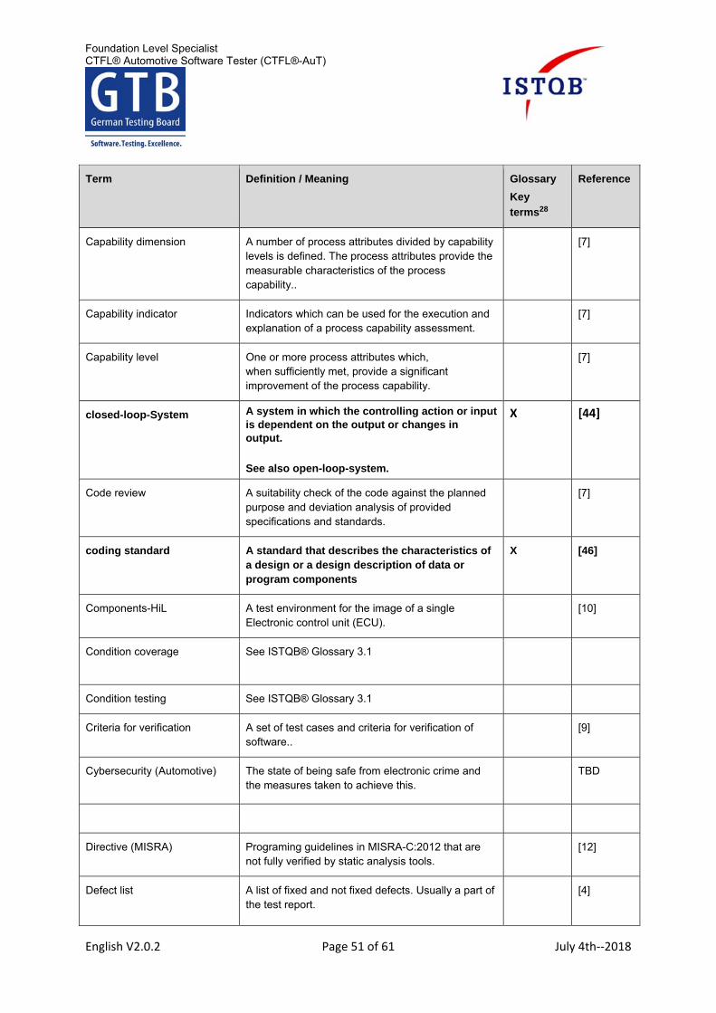
Foundation Level Specialist CTFL® Automotive Software Tester (CTFL®-AuT)
English V2.0.2 Page 51 of 61 July 4th‐‐2018
Term Definition / Meaning Glossary
Key
terms28
Reference
Capability dimension A number of process attributes divided by capability levels is defined. The process attributes provide the measurable characteristics of the process capability..
[7]
Capability indicator Indicators which can be used for the execution and explanation of a process capability assessment.
[7]
Capability level One or more process attributes which, when sufficiently met, provide a significant improvement of the process capability.
[7]
closed-loop-System A system in which the controlling action or input is dependent on the output or changes in output.
See also open-loop-system.
X [44]
Code review A suitability check of the code against the planned purpose and deviation analysis of provided specifications and standards.
[7]
coding standard A standard that describes the characteristics of a design or a design description of data or program components
X [46]
Components-HiL A test environment for the image of a single Electronic control unit (ECU).
[10]
Condition coverage See ISTQB® Glossary 3.1
Condition testing See ISTQB® Glossary 3.1
Criteria for verification A set of test cases and criteria for verification of software..
[9]
Cybersecurity (Automotive)
The state of being safe from electronic crime and the measures taken to achieve this.
TBD
Directive (MISRA) Programing guidelines in MISRA-C:2012 that are not fully verified by static analysis tools.
[12]
Defect list A list of fixed and not fixed defects. Usually a part of the test report.
[4]
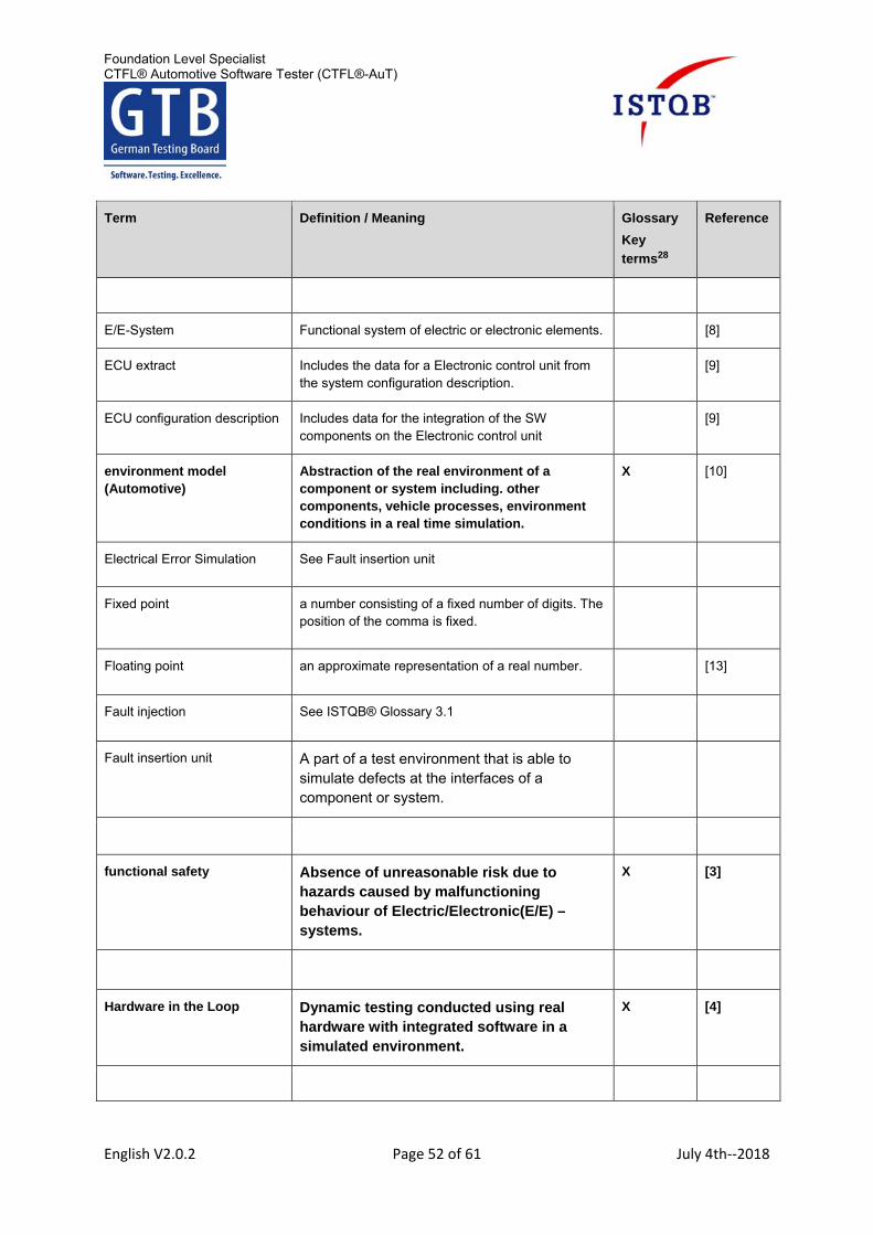
Foundation Level Specialist CTFL® Automotive Software Tester (CTFL®-AuT)
English V2.0.2 Page 52 of 61 July 4th‐‐2018
Term Definition / Meaning Glossary
Key
terms28
Reference
E/E-System Functional system of electric or electronic elements. [8]
ECU extract Includes the data for a Electronic control unit from the system configuration description.
[9]
ECU configuration description Includes data for the integration of the SW components on the Electronic control unit
[9]
environment model (Automotive)
Abstraction of the real environment of a component or system including. other components, vehicle processes, environment conditions in a real time simulation.
X [10]
Electrical Error Simulation See Fault insertion unit
Fixed point a number consisting of a fixed number of digits. The position of the comma is fixed.
Floating point an approximate representation of a real number. [13]
Fault injection
See ISTQB® Glossary 3.1
Fault insertion unit A part of a test environment that is able to simulate defects at the interfaces of a component or system.
functional safety Absence of unreasonable risk due to hazards caused by malfunctioning behaviour of Electric/Electronic(E/E) – systems.
X [3]
Hardware in the Loop Dynamic testing conducted using real hardware with integrated software in a simulated environment.
X [4]
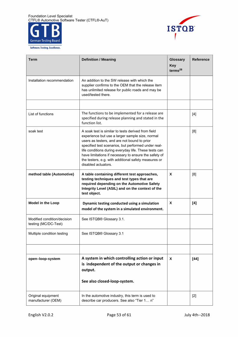
Foundation Level Specialist CTFL® Automotive Software Tester (CTFL®-AuT)
English V2.0.2 Page 53 of 61 July 4th‐‐2018
Term Definition / Meaning Glossary
Key
terms28
Reference
Installation recommendation An addition to the SW release with which the supplier confirms to the OEM that the release item has unlimited release for public roads and may be used/tested there.
List of functions The functions to be implemented for a release are specified during release planning and stated in the function list.
[4]
soak test A soak test is similar to tests derived from field experience but use a larger sample size, normal users as testers, and are not bound to prior specified test scenarios, but performed under real-life conditions during everyday life. These tests can have limitations if necessary to ensure the safety of the testers, e.g. with additional safety measures or disabled actuators.
[8]
method table (Automotive) A table containing different test approaches, testing techniques and test types that are required depending on the Automotive Safety Integrity Level (ASIL) and on the context of the test object.
X [8]
Model in the Loop Dynamic testing conducted using a simulation
model of the system in a simulated environment.
X [4]
Modified condition/decision testing (MC/DC-Test)
See ISTQB® Glossary 3.1.
Multiple condition testing See ISTQB® Glossary 3.1
open–loop-system A system in which controlling action or input
is independent of the output or changes in
output.
See also closed‐loop‐system.
X [44]
Original equipment manufacturer (OEM)
In the automotive industry, this term is used to describe car producers. See also “Tier 1… n”
[2]
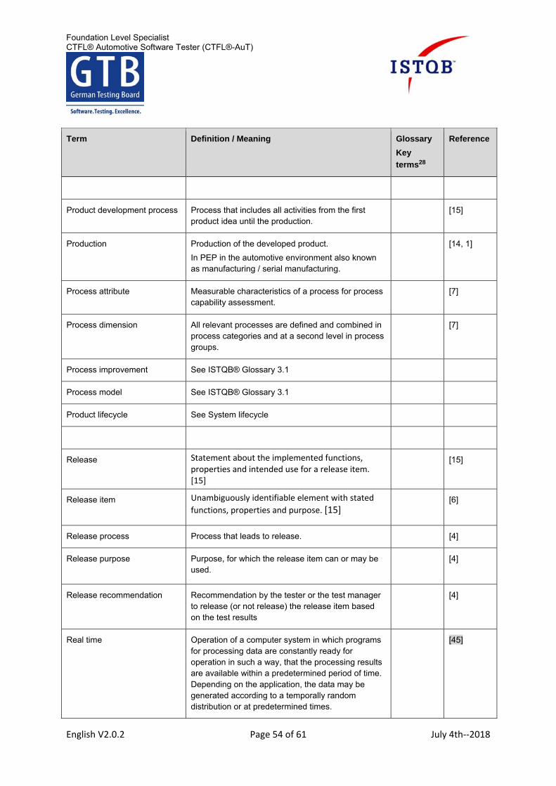
Foundation Level Specialist CTFL® Automotive Software Tester (CTFL®-AuT)
English V2.0.2 Page 54 of 61 July 4th‐‐2018
Term Definition / Meaning Glossary
Key
terms28
Reference
Product development process Process that includes all activities from the first product idea until the production.
[15]
Production Production of the developed product.
In PEP in the automotive environment also known as manufacturing / serial manufacturing.
[14, 1]
Process attribute Measurable characteristics of a process for process capability assessment.
[7]
Process dimension All relevant processes are defined and combined in process categories and at a second level in process groups.
[7]
Process improvement See ISTQB® Glossary 3.1
Process model See ISTQB® Glossary 3.1
Product lifecycle See System lifecycle
Release Statement about the implemented functions, properties and intended use for a release item. [15]
[15]
Release item
Unambiguously identifiable element with stated
functions, properties and purpose. [15] [6]
Release process Process that leads to release. [4]
Release purpose
Purpose, for which the release item can or may be used.
[4]
Release recommendation Recommendation by the tester or the test manager to release (or not release) the release item based on the test results
[4]
Real time Operation of a computer system in which programs for processing data are constantly ready for operation in such a way, that the processing results are available within a predetermined period of time. Depending on the application, the data may be generated according to a temporally random distribution or at predetermined times.
[45]
Foundation Level Specialist CTFL® Automotive Software Tester (CTFL®-AuT)
English V2.0.2 Page 55 of 61 July 4th‐‐2018
Term Definition / Meaning Glossary
Key
terms28
Reference
Real time capable computer A computing unit that guarantees the processing of signals
in a defined window of time.
[10]
Reference Process See ISTQB® Glossary 3.1
Regression test strategy The regression test strategy defines which criteria are used to select the regression test cases when there is a change to the test item.
Rest bus simulation Virtualization of the bus communication interface of non-existing electronic control units.
Rule (MISRA) Programming Guideline in MISRA-C:2012 which is verifiable by static analysis tools.
[12]
Runtime environment (AUTOSAR)
The abstraction layer, which controls and implements the data exchange between AUTOSAR software components as well as between application and Base Software (BSW), inside as well as outside of the control units
[9]
Safety Culture The company-wide attitude to commonly develop a functionally safe product.
[8]
Safety lifecycle Product lifecycle of a safety relevant system. It starts with the product idea and ends with the disposal of the product at the end of its lifecycle.
[8]
Simulation time The timeframe, which is valid for a computer simulation.
[10]
Software component The (AUTOSAR): hardware-independent software layer which includes the individual applications and functionalities.
[9]
Software in the loop (SiL) Dynamic testing conducted using the real software in a simulated environment or with experimental hardware.
X [4]
software qualification test (ASPICE)
Testing conducted on a completed, integrated software to provide evidence for compliance with the software requirements.
X [9]
Foundation Level Specialist CTFL® Automotive Software Tester (CTFL®-AuT)
English V2.0.2 Page 56 of 61 July 4th‐‐2018
Term Definition / Meaning Glossary
Key
terms28
Reference
System-HiL A test environment for the image of a electronic control unit group up to the entire vehicle.
[10]
System integration test (ASPICE)
Testing against the system architectural design to provide evidence for compliance of the integrated system items with the system architectural design, including the interfaces between system items.
[9]
System configuration description
The data used in the integration of all electronic control units in a vehicle.
[9]
System lifecycle The phases of development and implementation of a system beyond the PEP until its retirement.
[15, 1, 14]
system qualification test (ASPICE)
Testing conducted on the completed, integrated system of software components, hardware components and mechanics to provide evidence for compliance with the system requirements and that the complete system is ready for delivery.
X [9]
System of systems testing Testing a system of systems to verify that it meets specified requirements.
Test item 1. See ISTQB® Glossary
2. Test item in the automotive context consists of a software configuration including basic parameterization and usually also a hardware and mechanics. [6]
[4]
Tier 1…n The suppliers in the supply chain on the different levels are named Tier 1…n. The direct suppliers of the OEM are called Tier 1, the suppliers of a Tier 1 are called Tier 2, etc.
[2]
Test documentation Documentation describing plans for, or results of, the testing of a system or component. [ISO/IEC/IEEE 24765]
[46]
Test strategy See ISTQB® Glossay 3.1
Traceability See ISTQB® Glossary 3.1
Foundation Level Specialist CTFL® Automotive Software Tester (CTFL®-AuT)
English V2.0.2 Page 57 of 61 July 4th‐‐2018
Term Definition / Meaning Glossary
Key
terms28
Reference
Verification criteria Verification criteria defining qualitative and quantitative criteria which must be fulfilled to successfully verify a test item.
[7]
Verification strategy A high-level plan for the verification of an item containing
verification criteria, verification activities with associated methods, techniques and tools, and work products or processes under verification.
[7]
XiL test environment A generic term for dynamic testing in different virtual test environments.
See also
Hardware in the Loop, Software in the Loop,
Model in the Loop
X
Foundation Level Specialist CTFL® Automotive Software Tester (CTFL®-AuT)
English V2.0.2 Page 58 of 61 July 4th‐‐2018
Abbreviations
The following abbreviations are used in this syllabus:
Abbreviation Definition / Meaning Reference
ACQ Acquisition [7]
ASIL Automotive Safety Integrity Level [8]
ASAM Association for Standardisation of Automation and Measuring Systems
[18]
ASPICE Automotive SPICE
AUTOSAR Automotive Open System Architecture
[9]
AUTOSIG Automotive Specific Interest Group [17]
BP Base Practice [7]
BSW Base Software [9]
CTFL® Certified Tester Foundation Level
E/E Electric / Electronic
ECU Electronic Control Unit
EES Electrical Error Simulation [16]
EOP End-of-Production
FIU Fault Insertion Unit [18]
GP Generic Practice [7]
HiL Hardware-in-the-Loop
IEC International Electrotechnical Commission
ISO International Organization for Standardization
Foundation Level Specialist CTFL® Automotive Software Tester (CTFL®-AuT)
English V2.0.2 Page 59 of 61 July 4th‐‐2018
ISTQB® International Software Testing Qualifications Board
MAN Management (ASPICE) [7]
MC/DC Modified Condition/Decision Coverage
MIL Model in the loop
MISRA Motor Industry Software Reliability Association
OEM Original Equipment Manufacturer
PA Process Attribute [7]
PEP Product Evolution Process [15]
PIM Process Improvement (ASPICE) [7]
QM Quality Management
REU Reuse (ASPICE) [7]
RTE Run Time Environment [9]
SIL Software in the Loop
SOP Start-of-Production
SPICE Software Process Improvement and Capability Determination
[7]
SPL Supply (ASPICE) [7]
SUP Support (ASPICE) [7]
SW Software
SW-C Software Component [9]
SWE Software Engineering (ASPICE) [7]
SYS System Engineering (ASPICE) [7]
VDA German Association of the Automotive Industry
WP Work Product [7]
Foundation Level Specialist CTFL® Automotive Software Tester (CTFL®-AuT)
English V2.0.2 Page 60 of 61 July 4th‐‐2018
Index
A
acceptance test 28
ASIL 24 Automotive SPICE 16 AUTOSAR 26
B
back-to-back-testing 41
C
Closed-Loop system 31
coding guidelines 38 component test 28
condition coverage 40 condition testing 40 criteria for verification 20
D
display of levels 17
E
environment model 31, 33
F
fault injection 41 functional safety 21
H
Hardware in the Loop 34
I
integration 26 integration test 28
M
MC/DC-Test 40 method tables 24, 29 Model in the Loop 33 modified condition/decision testing 40 multiple condition test 40 multi‐system test 28
O
Open-Loop-System 31
P
process category 17 process group 17 process improvement 16, 17 process models 16
Q
quality characteristics 39
R
reference processes 16 regression test strategy 19 release 14 release item 14
Requirements-based testing 42
XCP Universal Measurement and Calibration Protocol
[19]
XIL Stands as upper tem for different in the Loop
Foundation Level Specialist CTFL® Automotive Software Tester (CTFL®-AuT)
English V2.0.2 Page 61 of 61 July 4th‐‐2018
S
safety life cycle 21 software component verification 18 Software in the Loop 34 software qualification test 18 system integration test 18, 27, 28 system life cycle 13 system qualification test 18 system test 27, 28
T
test documentation 19
test levels 23, 27, 28 test strategy 19 traceability 20
V
verification 22, 23, 28 verification strategy 19
X
XiL test environments 33