Embed Size (px)
Citation preview

Foundation Selection
Considering Impact to
Adjacent Structures
Ching Tsai, Ph.D., P.E.
Albert Ayenu-Prah, Ph.D., P.E.

Presentation Outline
Typical Foundation Selection Process
Special Considerations
Structure Movement Tolerance
Evaluation Methods
Case Studies
Typical Foundation Selection Process
Soil Conditions
Loads
Environmental Considerations
Availability of Contractors
Local Practices
Design Constraints
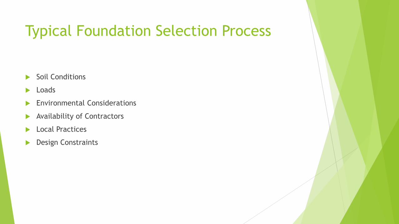
Special Considerations – Adjacent
Structures Excavation
Buried Structures
Congested Sites
Additional Loads
Structure Expansion
The leaning tower of Shanghai
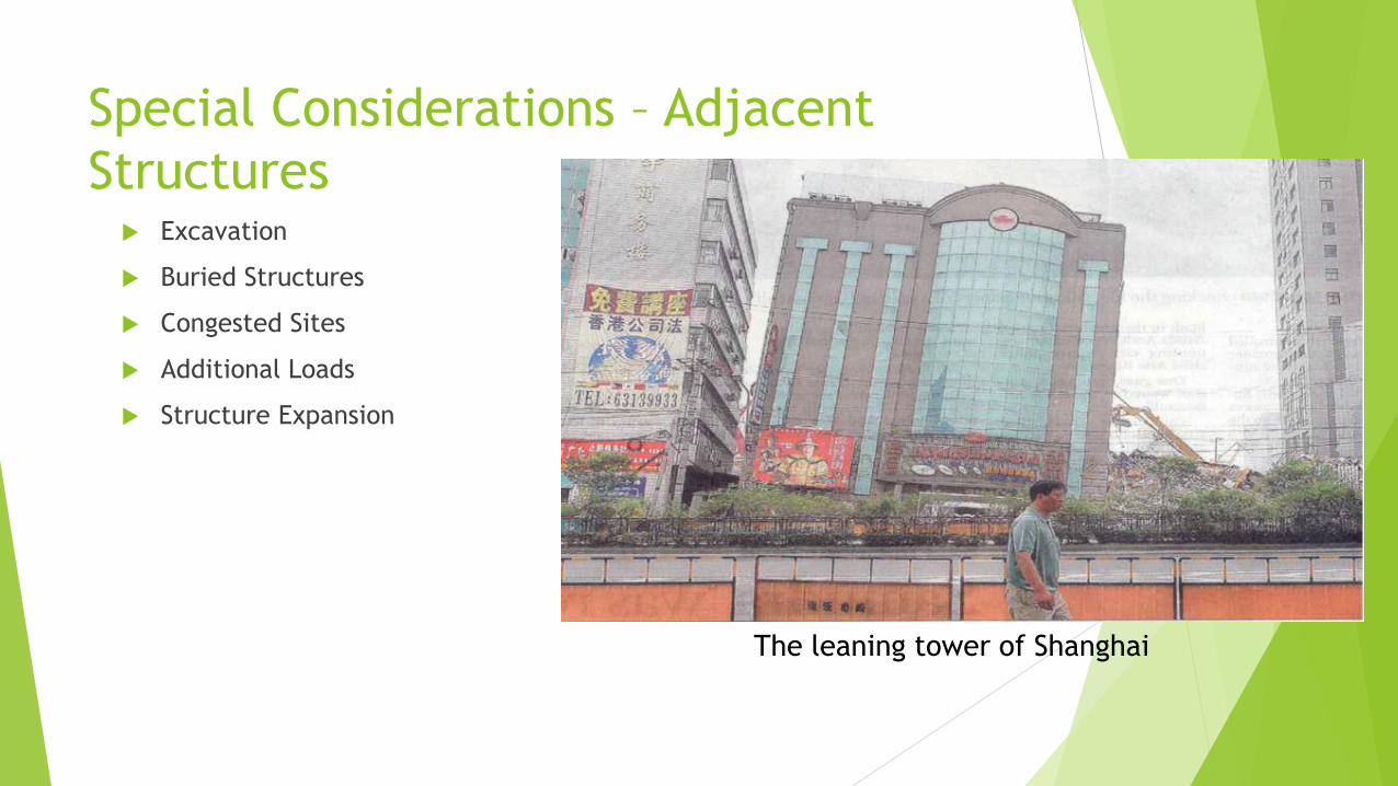
Piles Near an Excavation
Sao Paulo, 2007
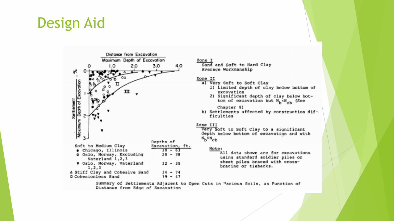
Design Aid

Excavation-Induced Lateral Movements
in Clay

Piles near Underground Structures
What is the effect of buried structure construction on adjacent piles?
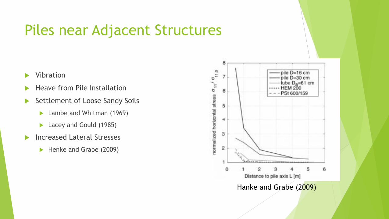
Piles near Adjacent Structures
Vibration
Heave from Pile Installation
Settlement of Loose Sandy Soils
Lambe and Whitman (1969)
Lacey and Gould (1985)
Increased Lateral Stresses
Henke and Grabe (2009)
Hanke and Grabe (2009)
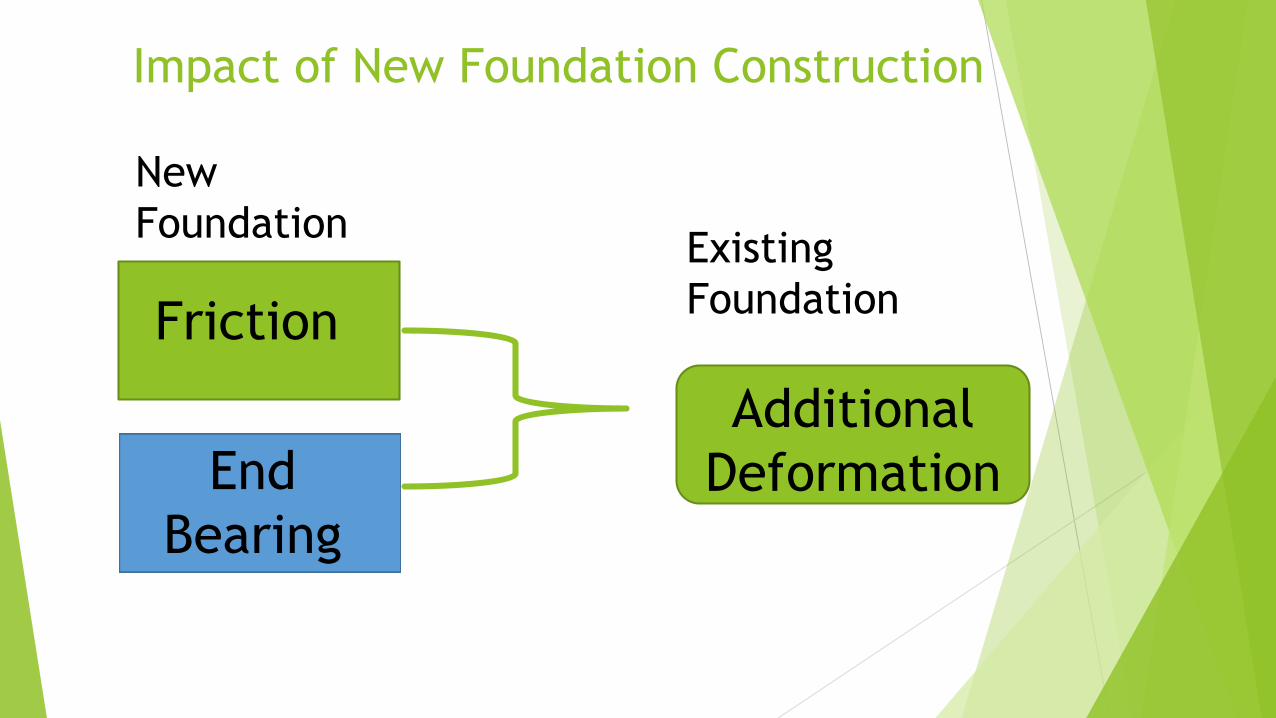
Impact of New Foundation Construction
Friction
End
Bearing
New
Foundation
Additional
Deformation
Existing
Foundation
Tolerable Movement Criteria
Current AASHTO
C10.5.2.2 Distortion Limits
Simple Span: 0.008 radians
Continuous Span: 0.004 radians
No Guidance on Transverse Differential Movement
Other Studies
DiMillio – observed 148 bridges – tolerable settlement 1-3 inches
Wahls – 1/250 of span length with vertical differential movements of 2 to 4 inches
Mouton – longitudinal distortion 0.004 radians for continuous and 0.005 radians for
simply supported bridges
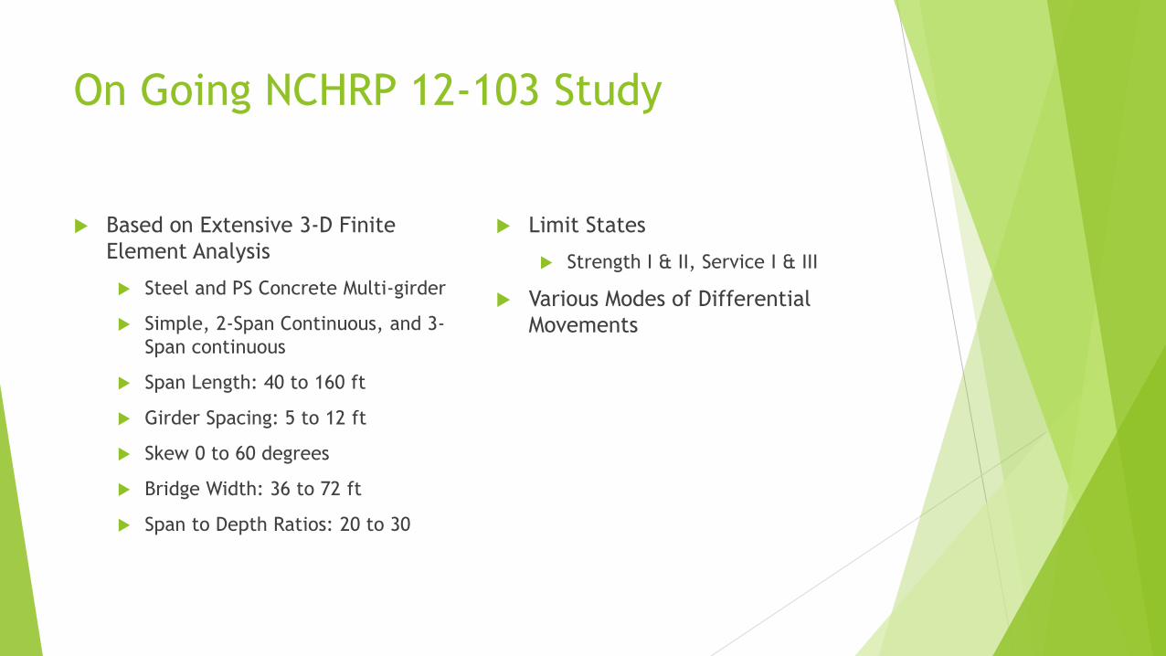
On Going NCHRP 12-103 Study
Based on Extensive 3-D Finite
Element Analysis
Steel and PS Concrete Multi-girder
Simple, 2-Span Continuous, and 3-
Span continuous
Span Length: 40 to 160 ft
Girder Spacing: 5 to 12 ft
Skew 0 to 60 degrees
Bridge Width: 36 to 72 ft
Span to Depth Ratios: 20 to 30
Limit States
Strength I & II, Service I & III
Various Modes of Differential
Movements
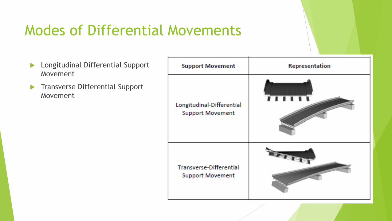
Modes of Differential Movements
Longitudinal Differential Support
Movement
Transverse Differential Support
Movement
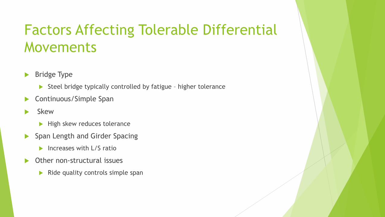
Factors Affecting Tolerable Differential
Movements
Bridge Type
Steel bridge typically controlled by fatigue – higher tolerance
Continuous/Simple Span
Skew
High skew reduces tolerance
Span Length and Girder Spacing
Increases with L/S ratio
Other non-structural issues
Ride quality controls simple span
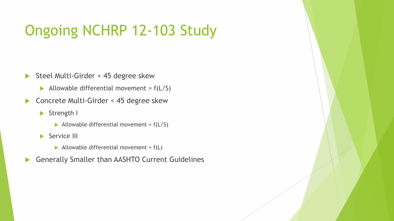
Ongoing NCHRP 12-103 Study
Steel Multi-Girder < 45 degree skew
Allowable differential movement = f(L/S)
Concrete Multi-Girder < 45 degree skew
Strength I
Allowable differential movement = f(L/S)
Service III
Allowable differential movement = f(L)
Generally Smaller than AASHTO Current Guidelines
Methods of Evaluation of Additional Movements
Elastic Solutions
Hybrid Model
Numerical Modeling
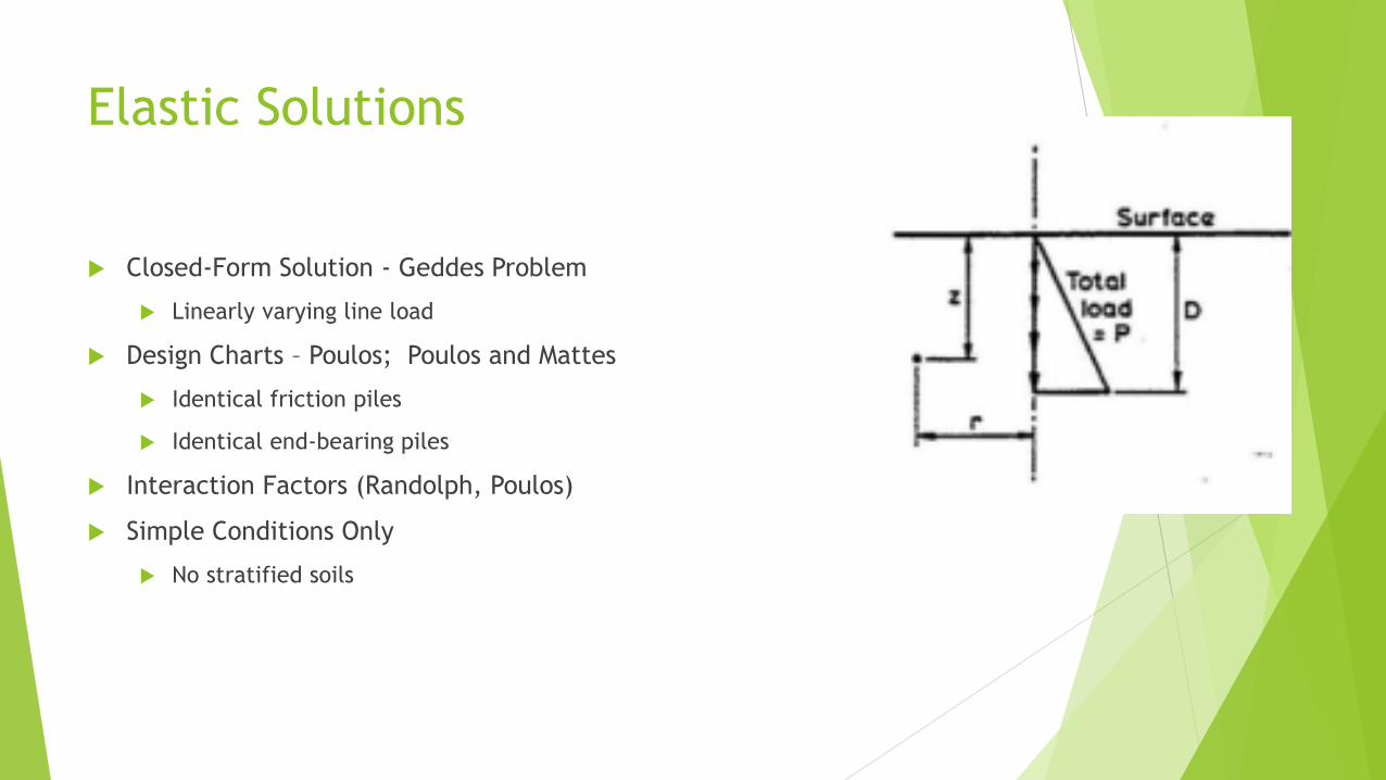
Elastic Solutions
Closed-Form Solution - Geddes Problem
Linearly varying line load
Design Charts – Poulos; Poulos and Mattes
Identical friction piles
Identical end-bearing piles
Interaction Factors (Randolph, Poulos)
Simple Conditions Only
No stratified soils
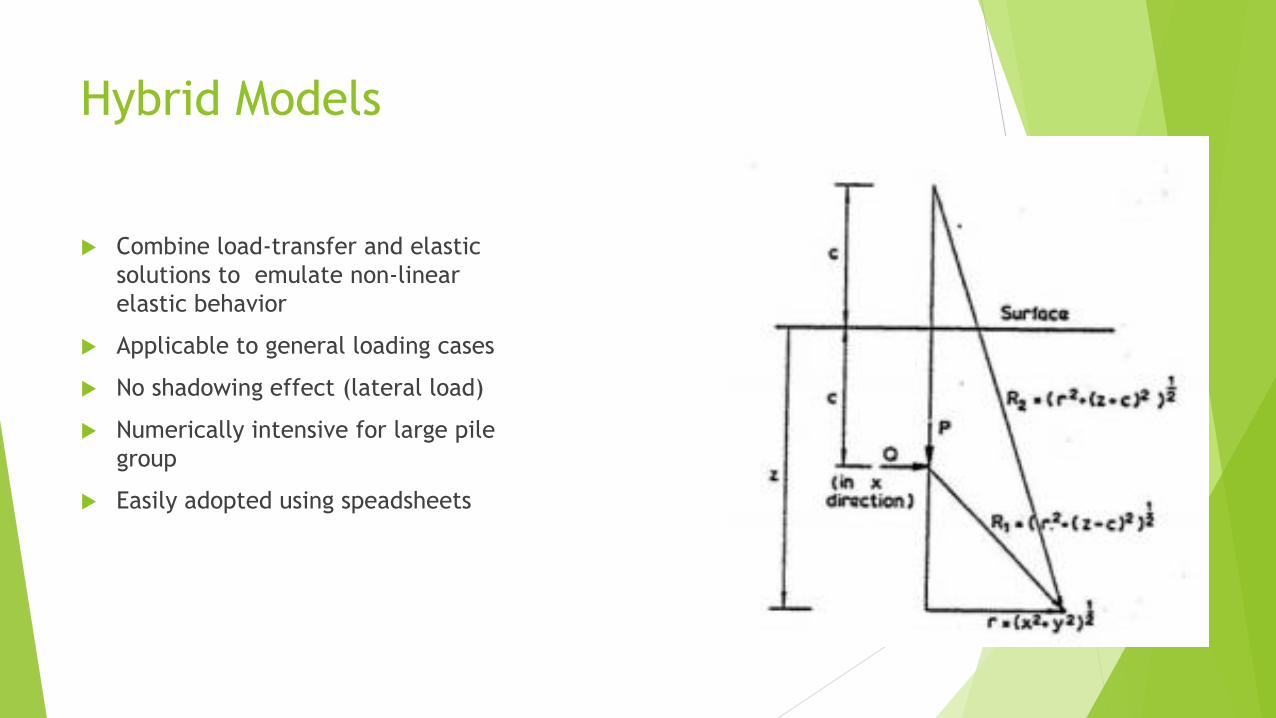
Hybrid Models
Combine load-transfer and elastic
solutions to emulate non-linear
elastic behavior
Applicable to general loading cases
No shadowing effect (lateral load)
Numerically intensive for large pile
group
Easily adopted using speadsheets

Numerical Models
Limited by modeling software
Complicated input
Numerically intensive
GIGO – if not modeled correctly

Hybrid Model Issues
Limit States
Strength I & II
Service I
Single Piles or Small Pile Group
Layered soils
Load transfer
Large Pile Groups
All issues from single piles
Pile-soil-pile interaction
Load transfer curves do not apply

Case History – McArthur Drive

Existing Structure
Multi Box-Girder Bridge
Span: 176 feet
Girder Spacing: 10 feet
Foundation:
14-in square concrete pile groups
56 to 68 100’ long pile groups
Estimated Longitudinal Differential Movement Tolerance – 8.4 inches
Based on current AASHTO
Estimated Transverse Differential Movement Tolerance – 1.5 inches
Based on NCHRP 12-103
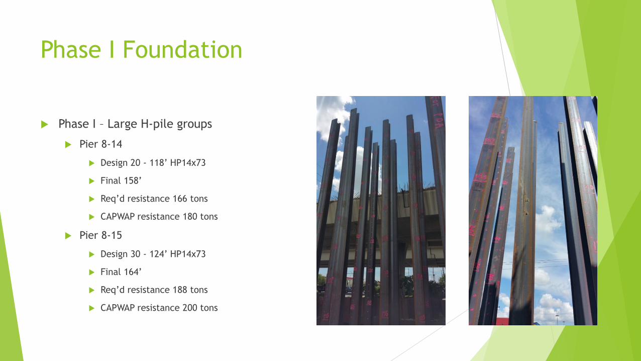
Phase I Foundation
Phase I – Large H-pile groups
Pier 8-14
Design 20 - 118’ HP14x73
Final 158’
Req’d resistance 166 tons
CAPWAP resistance 180 tons
Pier 8-15
Design 30 - 124’ HP14x73
Final 164’
Req’d resistance 188 tons
CAPWAP resistance 200 tons
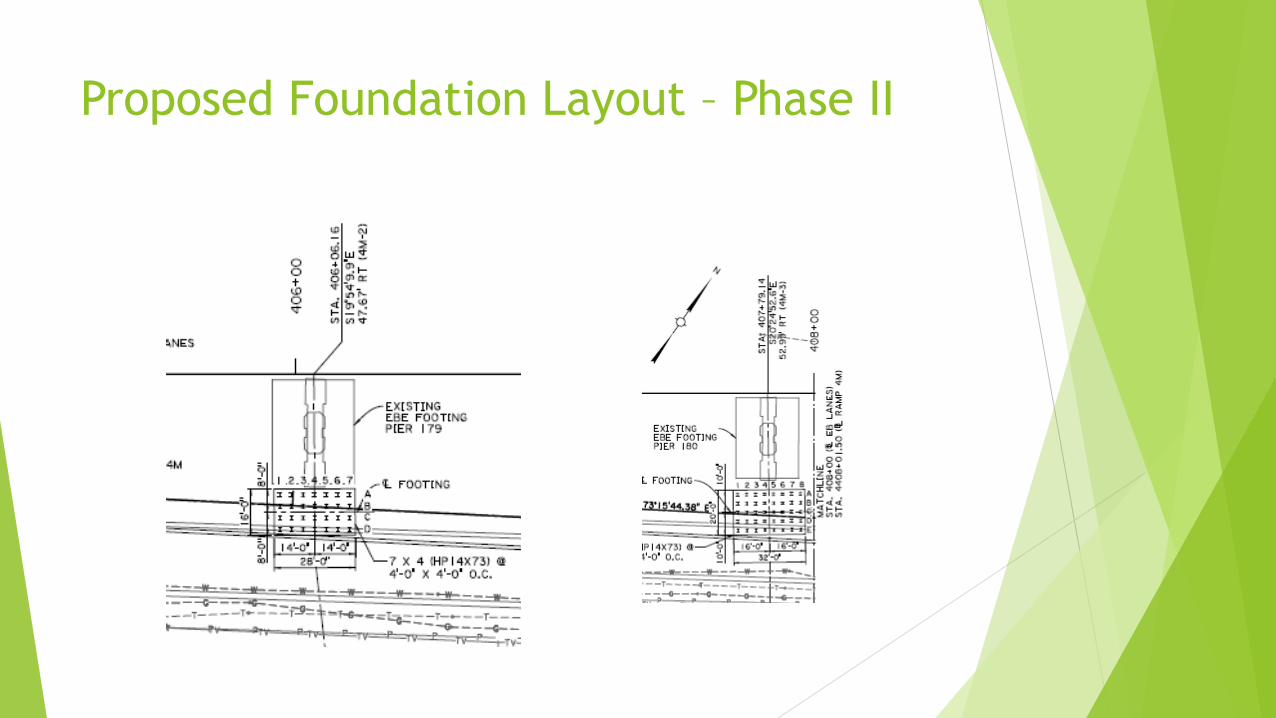
Proposed Foundation Layout – Phase II

More…
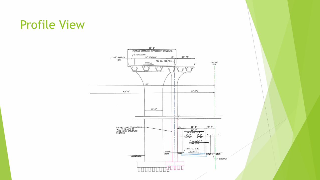
Profile View
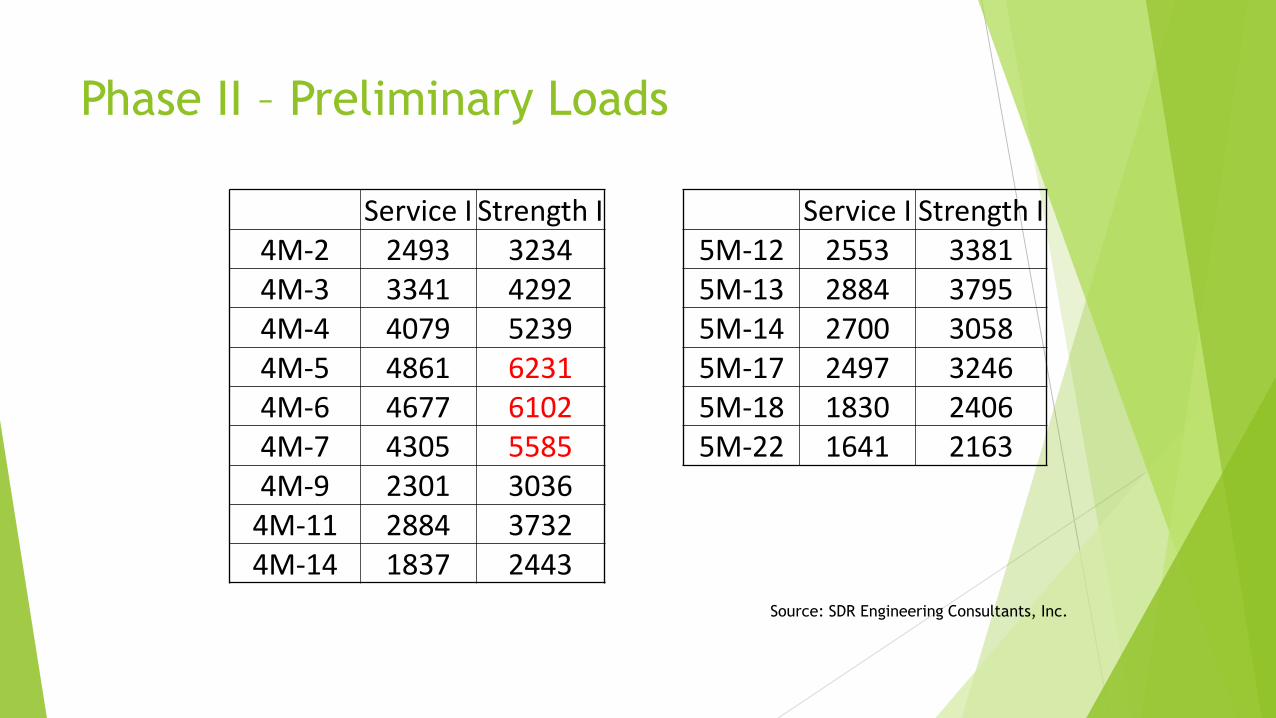
Phase II – Preliminary Loads
Service I Strength I Service I Strength I4M-2 2493 3234 5M-12 2553 33814M-3 3341 4292 5M-13 2884 37954M-4 4079 5239 5M-14 2700 30584M-5 4861 6231 5M-17 2497 32464M-6 4677 6102 5M-18 1830 24064M-7 4305 5585 5M-22 1641 21634M-9 2301 3036
4M-11 2884 37324M-14 1837 2443
Source: SDR Engineering Consultants, Inc.
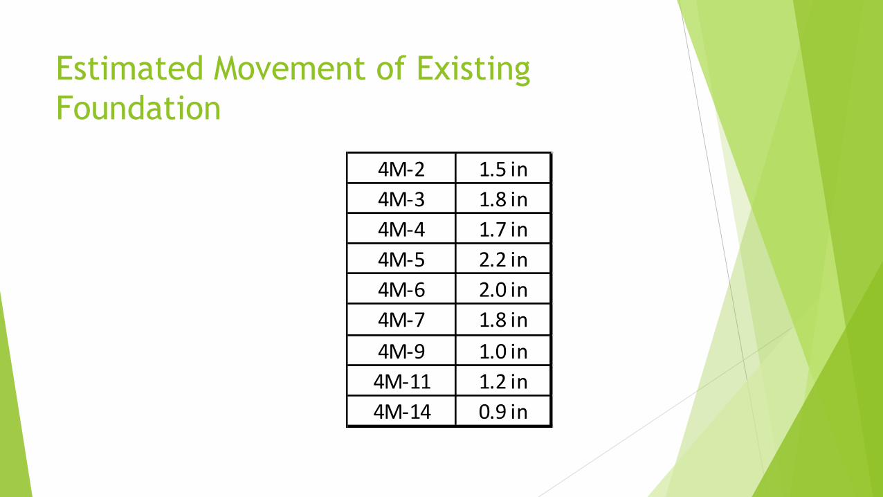
Estimated Movement of Existing
Foundation
4M-2 1.5 in
4M-3 1.8 in
4M-4 1.7 in
4M-5 2.2 in
4M-6 2.0 in
4M-7 1.8 in
4M-9 1.0 in
4M-11 1.2 in
4M-14 0.9 in
Foundation Selection Consideration
Noise & Vibration
Installation & Staging
Additional Transverse Foundation Movement > 1.5”
Options
Underpinning the existing foundation – impractical
Transmit the load to deeper soils
Long drilled shaft with tip grouting (approx. 50% end bearing)
Estimated movement < 0.5 in.
The Message
Consider all possible impacts
Communication among design and construction disciplines
Assessment of ground movement is critical
Adopt Observational Method
Predict
Set action level
Measure
Compare
Take action, if necessary

THANKS
Ching Tsai, Ph.D., P.E.
Albert Ayenu-Prah,Ph.D., P.E.