Embed Size (px)
Citation preview

Budapesti Műszaki és Gazdaságtudományi Egyetem Méréstechnika és Információs Rendszerek Tanszék
Foundations of Model Transformation
Model Driven Systems Development Lecture 9-10

End-to-End Traceability
End
-to-En
d Trace
ability
Models and Transformations in Critical Systems
System Design Model
Architecture Design Model
Component Design Model
Refine
Refine
Model Transformations • systematic foundation of knowledge transfer: theoretical resultstools • bridge / integrate existing languages&tools
Design + V&V Artifacts (Source code, Glue code, Config. Tables, Test Cases, Monitors, Fault Trees, etc.)
Code Generation
Test Generation
Ve
rtical Mo
de
l Transfo
rmatio
ns
Component V&V Model
Architecture V&V Model
System V&V Model
Model generation
Back-Annotation
Model generation
Back-Annotation
Model generation
Back-Annotation
Use
Use
Horizontal Model Transformations
Formal methods
Formal methods
Design rules
Design rules
Design rules
Related projects • CESAR, SAVI, … • HIDE, DECOS, DIANA, MOGENTES, CERTIMOT, GENESYS, SENSORIA
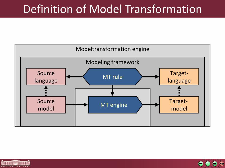
Definition of Model Transformation
Modeltransformation engine
Modeling framework
Source model
Source language
Target- model
Target- language
MT rule
MT engine

Modeltransformation engine
Modeling framework
Source model
Source language
Target- model
Target- language
MT rule
MT engine
Overview
Motivációs mintapélda
1. Motivating example
2. Modellezési nyelvek felépítése
2. Structure of modeling languages
3. Graph transformation rules
4. Execution of GT rules
5. Semantics
6. Effects of multiple rules
1. Motivating Example
Object Relational Schema mapping

Example: Object-relational maping
Important as:
o Model transformation benchmark
o Most widely used industrial model transformation (pl. Hibernate, EJB, CDO)
Objective:
o Input: UML class diagram
o Output Relational database schema

Informal definition of the MT rules of the mapping
Topmost (generalization) classes Database table + 2 column: •Unique identifier (primary key), • type definition

Informal definition of the MT rules of the mapping
Class attributes (contained by the topmost classes) Column of the table

Informal definition of the MT rules of the mapping
Type of the attributes foreign key

Informal definition of the MT rules of the mapping
Association A table with two columns • source and target identifiers • foreign keys (for consistency)

2. Structure of Modeling Languages
Revision

Book:Class
Customer:Class Product:Class
VIPCustomer:Class NormalCustomer:Class CD:Class
appendix:Attribute favourite:Attribute
reviews:Association
orders:Association
parent parent
attrs attrs
type
type
src dst
dst src
parent parent
Structure of Modeling languages (UML)
Abstract syntax o Graph based model
representation o Machine readable
Concrete syntax o Visual/textual
representation o Human readable

cref
Customer:Table Product:Table
CustId:Column
CustKind:Column
CustFavourite:Column
ProdId:Column
CustFFav:FKey
pkey
pkey
tcols tcols
fkeys fkeys
kcols
Structure of Modeling languages (RDBMS Schema)
Concrete syntax Abstract syntax

* Class
Association
Attribute
src dst
attrs type
parent
*
UML
* Column
* Table
FKey
fkeys
kcols
tcols
pkey cref
*
*
DB
*
tref
Asc2Tab
Cls2Tab
Attr2Col c2a
t2c
t2a
Ref
a2t
c2t
a2c
Metamodel of the O-R mapping Source + Target
metamodel
Traceability metamodel: o For saving the relations
between the source and the target languages
Motivation: critical embedded systems o Traceability
o Requirement Source code

3. Graph Transformation Rules

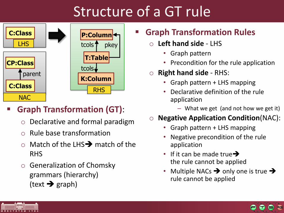
Structure of a GT rule
Graph Transformation (GT): o Declarative and formal paradigm
o Rule base transformation
o Match of the LHS match of the RHS
o Generalization of Chomsky grammars (hierarchy) (text graph)
Graph Transformation Rules o Left hand side - LHS
• Graph pattern
• Precondition for the rule application
o Right hand side - RHS:
• Graph pattern + LHS mapping
• Declarative definition of the rule application
– What we get (and not how we get it)
* C:Class
LHS RHS
T:Table
P:Column
tcols pkey
K:Column
tcols
Structure of a GT rule Graph Transformation Rules
o Left hand side - LHS • Graph pattern
• Precondition for the rule application
o Right hand side - RHS: • Graph pattern + LHS mapping
• Declarative definition of the rule application
– What we get (and not how we get it)
o Negative Application Condition(NAC): • Graph pattern + LHS mapping
• Negative precondition of the rule application
• If it can be made true the rule cannot be applied
• Multiple NACs only one is true rule cannot be applied
RHS
T:Table
P:Column
tcols pkey
K:Column
tcols
C:Class
LHS
* C:Class
parent
NAC
CP:Class
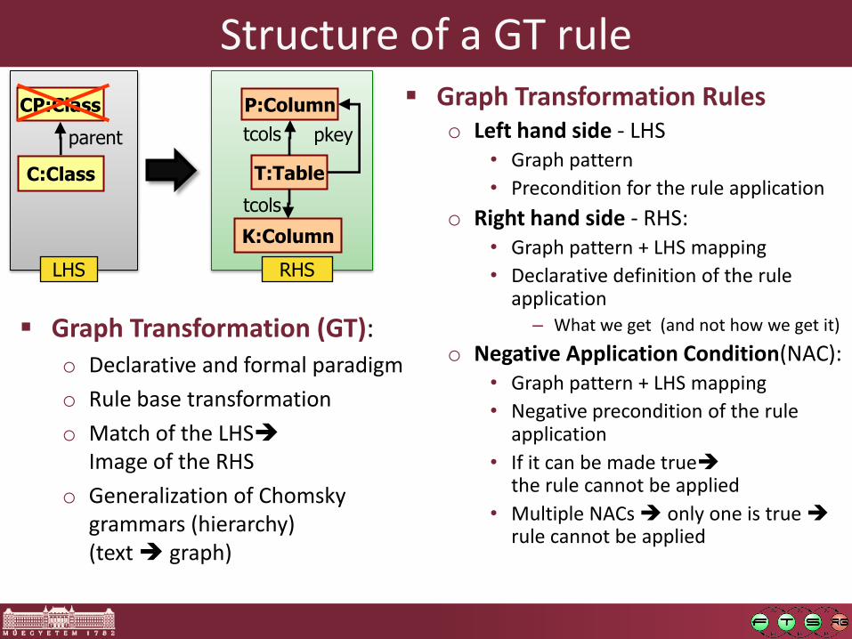
Graph Transformation (GT): o Declarative and formal paradigm
o Rule base transformation
o Match of the LHS match of the RHS
o Generalization of Chomsky grammars (hierarchy) (text graph)
Structure of a GT rule
RHS
T:Table
P:Column
tcols pkey
K:Column
tcols
* C:Class
parent
LHS
CP:Class
Graph Transformation (GT): o Declarative and formal paradigm
o Rule base transformation
o Match of the LHS Image of the RHS
o Generalization of Chomsky grammars (hierarchy) (text graph)
Graph Transformation Rules o Left hand side - LHS
• Graph pattern
• Precondition for the rule application
o Right hand side - RHS: • Graph pattern + LHS mapping
• Declarative definition of the rule application
– What we get (and not how we get it)
o Negative Application Condition(NAC): • Graph pattern + LHS mapping
• Negative precondition of the rule application
• If it can be made true the rule cannot be applied
• Multiple NACs only one is true rule cannot be applied

4. Application of Graph Transformation Rules

G (UML)
Book:Class
Customer:Class Product:Class
VIPCustomer:Class NormalCustomer:Class CD:Class
appendix:Attribute favourite:Attribute
reviews:Association
orders:Association
parent parent
attrs attrs
type
type
src dst
dst src
parent parent
Application of GT rules 1. Graph pattern matching
o Match of the LHS pattern in the underlying model
o match m: LHS G mapping
RHS
T:Table
P:Column
tcols pkey
K:Column
tcols
* C:Class
parent
LHS
CP:Class
G (UML)
Book:Class
Customer:Class Product:Class
VIPCustomer:Class NormalCustomer:Class CD:Class
appendix:Attribute favourite:Attribute
reviews:Association
orders:Association
parent parent
attrs attrs
type
type
src dst
dst src
parent parent
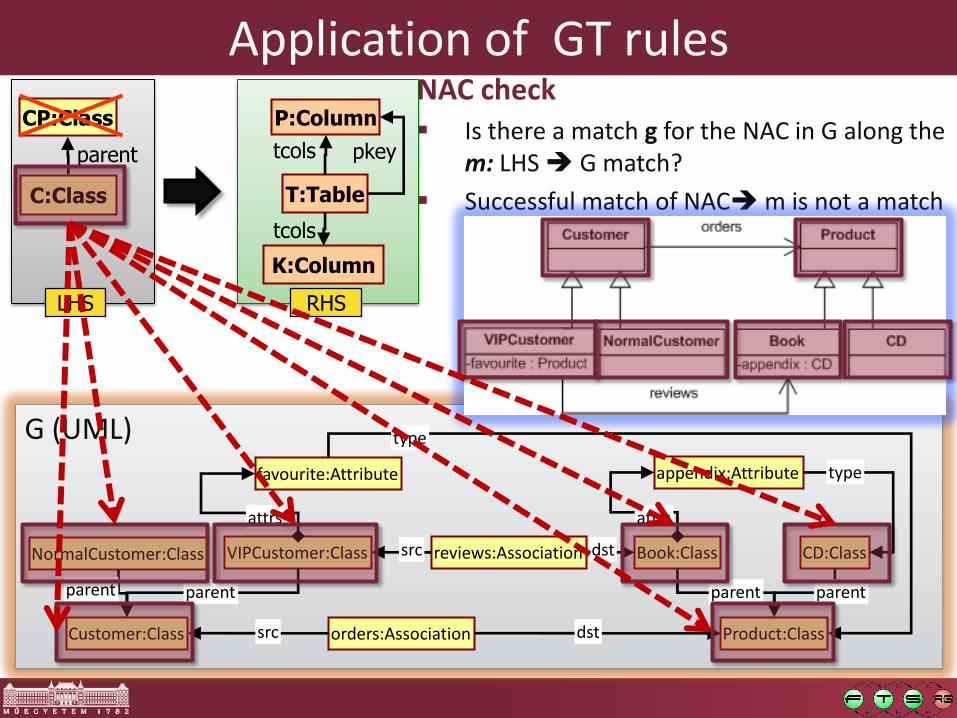
Application of GT rules NAC check Is there a match g for the NAC in G along the
m: LHS G match?
Successful match of NAC m is not a match
RHS
T:Table
P:Column
tcols pkey
K:Column
tcols
* C:Class
parent
LHS
CP:Class
G (UML)
Book:Class
Customer:Class Product:Class
VIPCustomer:Class NormalCustomer:Class CD:Class
appendix:Attribute favourite:Attribute
reviews:Association
orders:Association
parent parent
attrs attrs
type
type
src dst
dst src
parent parent
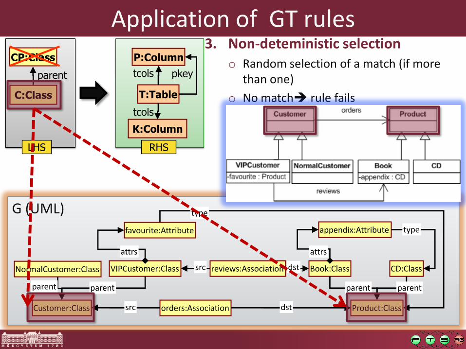
Application of GT rules 3. Non-deteministic selection
o Random selection of a match (if more than one)
o No match rule fails
RHS
T:Table
P:Column
tcols pkey
K:Column
tcols
* C:Class
parent
LHS
CP:Class

G (UML)
Book:Class
Customer:Class Product:Class
VIPCustomer:Class NormalCustomer:Class CD:Class
appendix:Attribute favourite:Attribute
reviews:Association
orders:Association
parent parent
attrs attrs
type
type
src dst
dst src
parent parent
Application of GT rules 4. Deletion
o Deletion of LHS \ RHS from G
o In LHS yes, in RHS no
RHS
T:Table
P:Column
tcols pkey
K:Column
tcols
* C:Class
parent
LHS
CP:Class

Application of GT rules 5. Creation (and binding)
o Creation of RHS \ LHS in G with their corresponding relations
o Output: a „match” of RHS in G
RHS
T:Table
P:Column
tcols pkey
K:Column
tcols
* C:Class
parent
LHS
CP:Class
G (DB) tCust:Table
CustId:Column
CustKind:Column
pkey
tcols

Typical problems…
RHS
T:Table * C:Class R:Cls2Tab
t2c c2t
C:Column
tcols pkey
K:Column
tcols
* C:Class
parent
LHS
CP:Class
1) Saving the source model, traceability
2) Application of the same rule along the same match
* C:Class
parent
LHS
CP:Class
R:Cls2Tab t2c
T:Table c2t
C:Column
tcols pkey
K:Column
tcols
* C:Class R:Cls2Tab
t2c
RHS
T:Table c2t
C:Column
tcols pkey
K:Column
tcols
The Image of C is the same
in G!

5. Different Semantics

G (UML)
Product:Class
VIPCustomer:Class NormalCustomer:Class
favourite:Attribute
orders:Association
attrs
type
dst
Semantics : Handling of Dangling edges Dangling edges:
o Delete a node • What to do with the
dangling edges?
Greedy approach
o Delete all dangling edges
o Pro: • Intuitive for engineers
• Easy to implement
o Con: • Verification is hard
(side effect of rules)
RHS
T:Table
P:Column
tcols pkey
K:Column
tcols
* C:Class
parent
LHS
CP:Class
Customer:Class
parent
src
parent

G (UML)
Product:Class
VIPCustomer:Class NormalCustomer:Class
favourite:Attribute
orders:Association
attrs
type
dst
parent
src
parent
Customer:Class
Semantics : Handling of Dangling edges Dangling edges:
o Delete a node • What to do with the dangling
edges?
Conservative approach o The rule cannot be applied if
it would produce a dangling edge
o Pro: • Side effect free rules
• Helps verification
o Con: • Harder to implement
• What is its meaning for engineers (not mathematicans)
RHS
T:Table
P:Column
tcols pkey
K:Column
tcols
* C:Class
parent
LHS
CP:Class

A:Assoc
src
RHS
CF:Class
A:Assoc
src
LHS
CF:Class
CT:Class
dst
G (UML)
VIPCustomer:Class NormalCustomer:Class
favourite:Attribute
orders:Association
attrs
parent
src
parent
Customer:Class
Semantics: Injective matching Injective matching
(„kisajátító”)
o For all nodes in the LHS separate nodes are matched in G
Pro:
o Intuitive for engineers
Con:
o Verbose specification of rules (many alternate subrules)
Product:Class dst
type
A:Assoc
src
RHS
CF:Class
A:Assoc
src
LHS
CF:Class
CT:Class
dst
G (UML)
VIPCustomer:Class NormalCustomer:Class
favourite:Attribute
orders:Association
attrs
parent
src
parent
Customer:Class
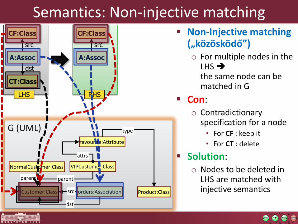
Semantics: Non-injective matching Non-Injective matching
(„közösködő”) o For multiple nodes in the
LHS the same node can be matched in G
Con: o Contradictionary
specification for a node • For CF : keep it
• For CT : delete
Solution: o Nodes to be deleted in
LHS are matched with injective semantics Product:Class
dst
type

6. Effects of Multiple GT Rules

A:Assoc
src
RHS
CF:Class
A:Assoc
src
LHS
CF:Class
CT:Class
dst
G (UML)
VIPCustomer:Class NormalCustomer:Class
favourite:Attribute
orders:Association
attrs
parent
src
parent
Customer:Class
Conflict / Parallel independence
Parallel independence (between two rule applications) o Neither prevents the application
of the other
Conflict (between two rule apps) o If they are not parallel
independent
Parallel independence (between two rules) o Any two of their rule application
are parallel independent Product:Class dst
type
A:Attrib
attrs
RHS
CF:Class
A:Attrib
attrs
LHS
CF:Class
CT:Class
type

A:Assoc
src
RHS
CF:Class
A:Assoc
src
LHS
CF:Class
CT:Class
dst
G1 (UML)
VIPCustomer:Class NormalCustomer:Class
favourite:Attribute
orders:Association
attrs
parent
src
parent
Customer:Class
Sequential independence
Sequential independence (two following rule applications) o Their order can be swapped
without any effect on their final result
Product:Class dst
type
A:Attrib
attrs
RHS
CF:Class
A:Attrib
attrs
LHS
CF:Class
CT:Class
type

A:Assoc
src
RHS
CF:Class
A:Assoc
src
LHS
CF:Class
CT:Class
dst
G2 (UML)
VIPCustomer:Class NormalCustomer:Class
favourite:Attribute
orders:Association
attrs
parent
src
parent
Customer:Class
Sequential independence
Sequential independence (two following rule applications) o Their order can be swapped
without any effect on their final result
Example Product:Class dst
type
A:Attrib
attrs
RHS
CF:Class
A:Attrib
attrs
LHS
CF:Class
CT:Class
type

A:Assoc
src
RHS
CF:Class
A:Assoc
src
LHS
CF:Class
CT:Class
dst
G1 (UML)
VIPCustomer:Class NormalCustomer:Class
favourite:Attribute
orders:Association
attrs
parent
src
parent
Customer:Class
Causal dependence I.
Sequential independence (two following rule applications)
o Their order can be swapped without any effect on their final result
Causally dependent (two following rule applications)
o If they are not serial independent
Product:Class dst
type
A:Attrib
attrs
RHS
CT:Class
A:Attrib
attrs
LHS
CF:Class
CT:Class
type

A:Assoc
src
RHS
CF:Class
A:Assoc
src
LHS
CF:Class
CT:Class
dst
G2 (UML)
NormalCustomer:Class
favourite:Attribute
orders:Association
VIPCustomer:Class
attrs
parent
src
parent
Customer:Class
Causally dependence II.
Serial independence (two following rule applications) o Their order can be swapped
without any effect on their final result
Causally dependent (two following rule applications) o If they are not serial
independent
Example Product:Class dst
type
A:Attrib
attrs
LHS
CF:Class
CT:Class
type
A:Attrib
attrs
RHS
CT:Class

Summary Graphtransformation,
as a modeltransformation paradigm o Rule and pattern based formal specification o Querying and manipulating graph based models o Intuitive graph based specification
Structure o LHS graph pattern: precondition o RHS graph pattern: postcondition o NAC: negative
condition
Rule application o Graph pattern matching o Deletition + Creation o Dangling edges and injectivity o Affect of multiple rule application (conflicts and causality)
*C:Class
parent
LHS
CP:Class
R:Cls2Tabt2c
T:Tablec2t
C:Column
tcols pkey
K:Column
tcols
*C:Class R:Cls2Tab
t2c
RHS
T:Tablec2t
C:Column
tcols pkey
K:Column
tcols

Chaining and Traceability of Model Transformations
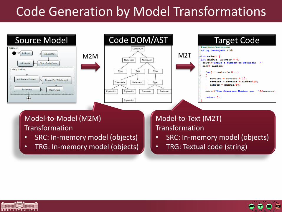
Code Generation by Model Transformations
Source Model Target Code Code DOM/AST
M2M M2T
Model-to-Model (M2M) Transformation • SRC: In-memory model (objects) • TRG: In-memory model (objects)
Model-to-Text (M2T) Transformation • SRC: In-memory model (objects) • TRG: Textual code (string)

Traceability in Model Transformations
Source Model Target Code Code DOM/AST
M2M M2T
Objective: • Support end-to-end traceability • REQ Model Code
Traceability links: • Additional links (edges) • Connect SRC and TRG models

Chaining of Model Transformations
Source Model Target Code Code DOM/AST
M2M M2T
Inter Model 1 Inter Model 2
M2M
M2M
M2M
Goal: • Reduce abstraction gap
by „divide and conquer” • Intermediate models • Chain of
model transformations

Model Transformation Flows / Chains
Source Model Target Code Code DOM/AST
M2T
Inter Model 1 Inter Model 1
M2M
M2M
M2M
Source Model 2
M2M
Joint optimization steps

Incrementality in model transformations

Incremental Forward Transformation
MSRC MTRG TRACE
M’SRC M’TRG TRACE’
1. First transformation
2. Source model changes
3. Apply changes to target model
Practical application scenarios: • Incremental model synchronization • Tool integration
Solutions: • Bidirectional transformations • Change-driven transformations

Incremental Backward Transformation
MSRC MTRG TRACE
M’SRC TRACE’ M’TRG
1. First transformation
2. Target model changes
3. Apply changes to source model
Challenge: SRCTRG specified TRGSRC inferred
Recent Approaches: A. Schürr, P. Stevens, N. Foster, T. Hettel, Cicchetti&Pierantonio, Czarnecki&Diskin
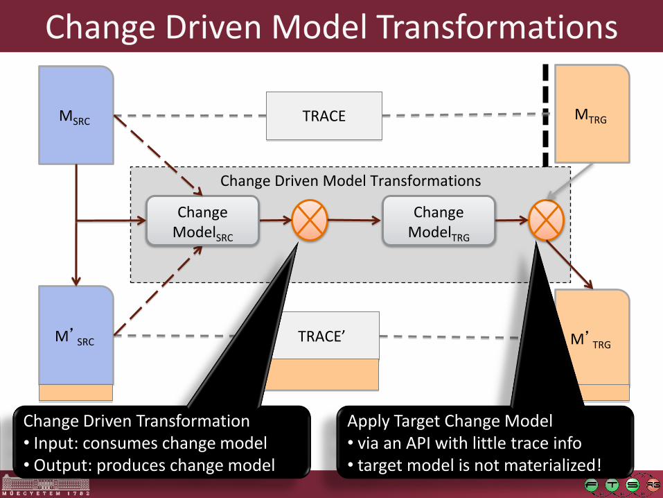
Change Driven Model Transformations
Change ModelTRG
Change Driven Model Transformations
MSRC MTRG TRACE
M’SRC M’TRG TRACE’
Change Driven Transformation • Input: consumes change model • Output: produces change model
Apply Target Change Model • via an API with little trace info • target model is not materialized!
Change ModelSRC

Levels of Incremental ity in Model Transformations

No Incrementality: Batch Transformations
1. First transformation
2. Source model changes
3. Re-execute from scratch for all source models
SRC1
SRC2
TRG1 TRACE1
TRG2 TRACE2
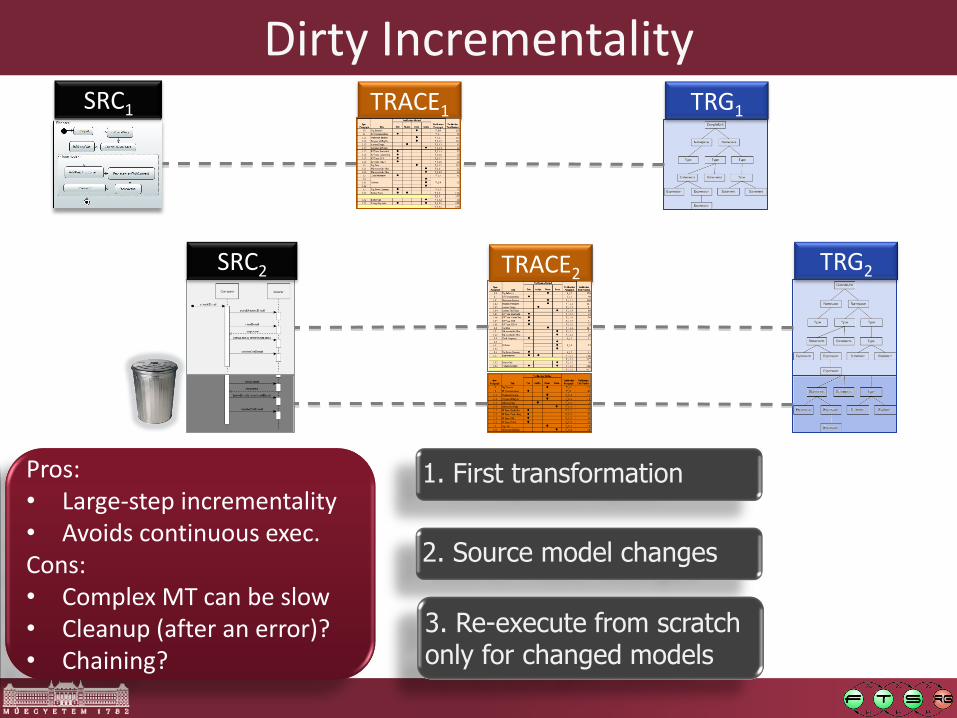
Dirty Incrementality
1. First transformation
2. Source model changes
3. Re-execute from scratch only for changed models
SRC1
SRC2
TRG1 TRACE1
TRG2 TRACE2
Pros: • Large-step incrementality • Avoids continuous exec. Cons: • Complex MT can be slow • Cleanup (after an error)? • Chaining?

Incrementality by Traceability
1. First transformation
2. Source model changes
4. Re-execute MT only for untraceable elements
SRC1
SRC2
TRG1 TRACE1
TRG2 TRACE2
3. Detect missing trace links
Pros: • Small-step incrementality • Better performance Cons: • Highly depends on
traceability links • Smart matcher needed

Event Driven Transformations
1. First transformation
2. Source model changes
4. Fire rule activations (in relevant context)
SRC1
SRC2
TRG1 TRACE1
TRG2 TRACE2
3. Detect new activations
Pros: • Refined context: driven by
changes of query result set • Chaining • Avoids continuous comp. Cons: • Language-level restrictions

Design Space Exploration
Á. Hegedüs, Á. Horváth, D. Varró: A model-driven framework for guided design space exploration. Automated Software Engineering (August 2014)
DOI: 10.1007/s10515-014-0163-1

Model-Driven Guided Design Space Exploration
End-to-End Traceability
End
-to-En
d Trace
ability
System Design Model
Architecture Design Model
Component Design Model
Refine
Refine
Design + V&V Artifacts (Source code, Glue code,
Config. Tables, Test Cases, Monitors, Fault Trees, etc.)
Code & Test Generation
Ve
rtical Mo
de
l Transfo
rmatio
ns
Component V&V Model
Architecture V&V Model
System V&V Model
Model generation
Back-Annotation Model generation
Back-Annotation Model generation
Back-Annotation
Use
Use
Horizontal Model Transformations
Formal methods
Formal methods
Design rules
Design rules
Design rules
Model-driven guided design space exploration • Quick fixes for DSMLs • Design of ARINC653 configs

Design Space Exploration
56
Design Space Exploration
Design Alternative 1
Design Alternative 2
Design Alternative 3
Design Alternative 4
Goals
Global Constraints
Operations
Initial Design
Special state space exploration • potentially infinite state space • „dense” solution space

Model Driven Guided Design Space Exploration
57
Design Space Exploration
Seq of Transf. Rules 1
Seq of Transf. Rules 2
Seq of Transf. Rules 3
Seq of Transf. Rules 4
Model queries as Goals
Model queries as Constraints
Transf. Rules as Operations
Initial Model
Guidance for exploration: Hints • designer / end user • formal analysis
Modified model
Operation
Initial model
Solution model
Constraints violated
Goals satisfied
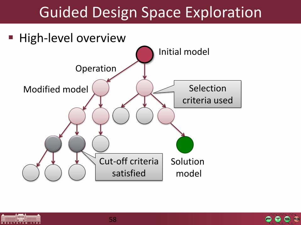
Guided Design Space Exploration
High-level overview
58
Initial model
Modified model
Operation
Solution model
Cut-off criteria satisfied
Selection criteria used
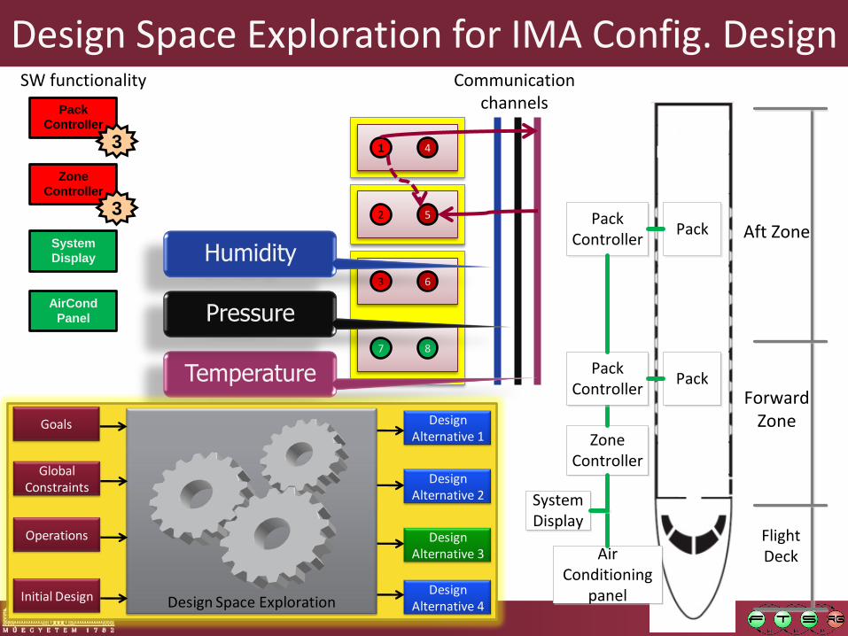
Design Space Exploration for IMA Config. Design
Pack
Controller
Zone
Controller
Aft Zone
ForwardZone
Flight DeckAir
Conditioning panel
System Display
Zone Controller
Pack Controller
Pack
Pack
Pack Controller
SW functionality
3
System
Display
AirCond
Panel
3
1
2
3
7
4
5
6
8
Communication channels
Temperature
Pressure
Humidity
Design Space Exploration
Design Alternative 1
Design Alternative 2
Design Alternative 3
Design Alternative 4
Goals
Global Constraints
Operations
Initial Design
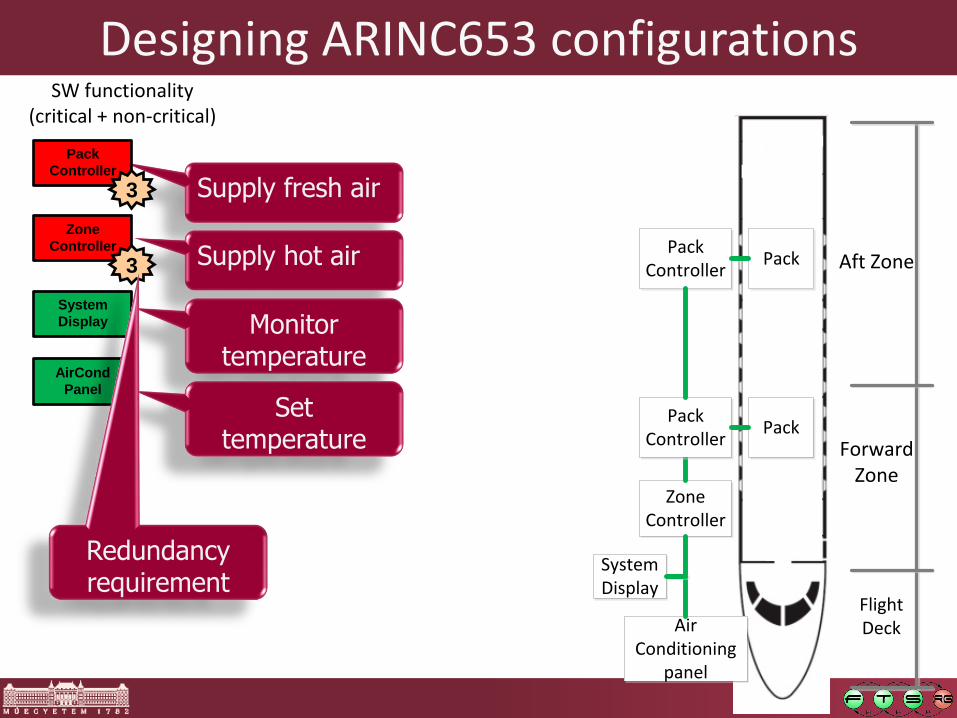
Supply fresh air
Supply hot air
Monitor temperature
Set temperature
Designing ARINC653 configurations
Pack
Controller
Zone
Controller
Aft Zone
ForwardZone
Flight DeckAir
Conditioning panel
System Display
Zone Controller
Pack Controller
Pack
Pack
Pack Controller
SW functionality (critical + non-critical)
3
System
Display
AirCond
Panel
3
Redundancy requirement

Job instances, Partitions, Modules
Pack
Controller
Zone
Controller
Aft Zone
ForwardZone
Flight DeckAir
Conditioning panel
System Display
Zone Controller
Pack Controller
Pack
Pack
Pack Controller
SW functionality (critical + non-critical)
3
System
Display
AirCond
Panel
3
1
2 3
7
Job instances
4
5 6
8
Partitions
Modules
Constraints
2
5
3
4
8
8
8
8
Memory needs + constraints
Do not mix critical and non-crit. jobs
Do not mix instances of the same critical job
Additional constraints • WCET, • scheduling, etc. • interfaces • datatypes

Allocating communication channels
Pack
Controller
Zone
Controller
Aft Zone
ForwardZone
Flight DeckAir
Conditioning panel
System Display
Zone Controller
Pack Controller
Pack
Pack
Pack Controller
SW functionality
3
System
Display
AirCond
Panel
3
1
2
3
7
4
5
6
8
Communication channels
Temperature
Pressure
Humidity

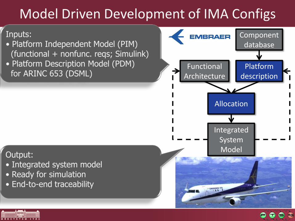
Model Driven Development of IMA Configs
Functional Architecture
Platform description
Component database
Allocation
Integrated System Model
Inputs: • Platform Independent Model (PIM) (functional + nonfunc. reqs; Simulink) • Platform Description Model (PDM) for ARINC 653 (DSML)
Output: • Integrated system model • Ready for simulation • End-to-end traceability

Model Driven Development of IMA Configs
Capture constraints
Explore alternatives
Human decision
Automate consequences
Functional Architecture
Platform description
Component database
Allocation
Integrated System Model
Model transformation chains: • Designer-guided manual steps • Automated steps
• design space exploration • optimization • code generators
• Continuous validation of design rules

Back-annotation of Verification Results
Based on ÁbelHegedüs’ PhD thesis

Overview: Back-Annotation of Execution Traces
Back-annotation of execution traces
End-to-End Traceability
End
-to-En
d Trace
ability
System Design Model
Architecture Design Model
Component Design Model
Refine
Refine
Design + V&V Artifacts (Source code, Glue code,
Config. Tables, Test Cases, Monitors, Fault Trees, etc.)
Code & Test Generation
Ve
rtical Mo
de
l Transfo
rmatio
ns
Component V&V Model
Architecture V&V Model
System V&V Model
Model generation
Back-Annotation Model generation
Back-Annotation Model generation
Back-Annotation
Use
Use
Horizontal Model Transformations
Formal methods
Formal methods
Design rules
Design rules
Design rules

Model Analysis: Motivation for BPEL
Requirement: Every received request must result in a reply! Will the business process assure this?
Receive request
Calculate Rating
Send offer
Accept?
Receive answer
Send reply
Send rejection
Receive update request
Update?
Rollback changes
Throw Error
Event: Cancel
Yes No
Yes No

Motivating scenario (cont.)
Requirement: Every received request must result in a reply!
Receive request
Calculate Rating
Send offer
Accept?
Receive answer
Send reply
Send rejection
Receive update request
Update?
Rollback changes
Throw Error
Event: Cancel
Yes No
Yes No

Motivating scenario (cont.)
Requirement: Every received request must result in a reply!
Receive request
Calculate Rating
Send offer
Accept?
Receive answer
Send reply
Send rejection
Receive update request
Update?
Rollback changes
Throw Error
Event: Cancel
Yes No
Yes No
Returns with a web-service error
Not executed = No reply

High-level
System Model
Model Based Analysis System design
Mathematical
model
Model
generation
Mathematical analysis
List of
inconsistencies Analysis (e.g model checker)
Fix problem Receive request
Calculate Rating
Send offer
Accept?
Receive answer
Send reply
Send rejection
Receiveupdate request
Update?YesNo
Yes No

Counter-example / Execution traces

Back-Annotation of Counter Example Traces
High-level
System Model Mathematical
model
Model
generation
Back-annotation
of target trace Analysis
(e.g model checker)
Replay of
source trace
Receive request
Calculate Rating
Send offer
Accept?
Receive answer
Send reply
Send rejection
Receiveupdate request
Update?YesNo
Yes No

Overview of Back-annotation
73

Challenges of Back-annotation
sf
si
sj
si
sj
sk
Multiple domain transitionsMultiple formal transitions
si
sd1sf1
sf2
No formaltransition
Independent transitions
sf3
sd2
Domain seq. Formalseq. Domain seq. Formalseq. Domain seq. Formalseq.
Domain seq. Formalseq.
sd1sf1
sf2
Spurious formalsequence
sf3
Domain seq. Formalseq.
sfsi sj
Alternative domain transitions
Domain seq. Formalseq.
(1) (2) (3)
(4) (5) (6)

Example: Back-Annotation
75
pt: PN Seq.
ps1: PN step ps2: PN step
Select Transition
Fire Transition
Select Transition
Fire Transition
next
d: Delete Token
c: Create Token
bt: BPEL Seq.
bs1: BPEL step
bs2: BPEL step
Activity Startable
Activity Runs
Activity Executed
substep
c1: Change State
c2: Change State
Fire Transition
Select Transition
Fire Transition
Select Transition
Add Tokens
Delete Tokens
BPEL Activity Executed
BPEL Activity Runs
BPEL Activity Startable

Example: Back-annotation
76
SD
sd1
sd2
sd3
sd4
sf1
sf2
sf3
sf4
calcRating
calcSecurity
flow
Fire Tr.
Fire Tr.
Fire Tr.
Start Flow
Invoke WS
Invoke WS
MF
MF
Throw Flt.
B2PN
B2PN
B2PN
B2PN
AD
Now processing
Processed
Legend
Simulation rule
Activation
Rule mapping
Correspondence link
Domain trace Formal trace
Fire Tr.
tor
tis
tir
tfs

Traceability by Soft Links
Á. Hegedüs, Á. Horváth, I. Ráth, R. R. Starr, D. Varró: Query Driven Soft Traceability Links for Models
(in review for Software and Systems Modeling)

Overview: Soft Traceability Links
End-to-End Traceability
End
-to-En
d Trace
ability
System Design Model
Architecture Design Model
Component Design Model
Refine
Refine
Design + V&V Artifacts (Source code, Glue code,
Config. Tables, Test Cases, Monitors, Fault Trees, etc.)
Code & Test Generation
Ve
rtical Mo
de
l Transfo
rmatio
ns
Component V&V Model
Architecture V&V Model
System V&V Model
Model generation
Back-Annotation Model generation
Back-Annotation Model generation
Back-Annotation
Use
Use
Horizontal Model Transformations
Formal methods
Formal methods
Design rules
Design rules
Design rules
Soft traceability links

Traceability as a V&V Challenge
End-to-end Traceability: • Required for certification • Any requirement lines of code • Any lines of code requirement
Functional Architecture
Platform description
Component database
Allocation
Integrated System Model
Model-based Traceability: • Traceability models
• linking FAM and PDM to IAM • integration with requirements tool (e.g. DOORS)
• Different tools? • Robustness?

Internal Traceability: EReferences

Traceability in Large EMF Models
Large EMF models
Split into fragments
Serialized separately in XMI files
Persisted in SVN, CVS
Hard links
Regular EReferences
Stored at source node
Model repository
Sys
s
d
j
Proc p
t1 t2
c
lp lct
ljt
li Op cl
cle
i m
lej

Problems with EMF-based Traceability Models
Modeling Scenario
Model Sys unloaded
Model repository
Sys
s
d
j
Proc p
t1 t2
c
lp lct
ljt
li Op cl
cle
i m
lej

Problems with EMF-based Traceability Models
Modeling Scenario
Model Sys unloaded
Model Proc changed
Model repository
Proc p
t1 t2
c
lp lct
Op cl
cle
i m

Problems with EMF-based Traceability Models
Modeling Scenario
Model Sys unloaded
Model Proc changed
Model Sys reloaded
Problems
Broken Link: runtime exception
Circular dependencies?
Model repository
Sys
s
d
j
lp lct
ljt
li Op cl
cle
i m
lej
Proc p
t1 t2
c

Soft Links for Traceability
Modeling Scenario
Model Sys unloaded
Model Proc changed
Model Sys reloaded
Problems
Broken Link: runtime exception
Circular dependencies?
Warning message
Soft Links: • Link exists only at runtime • Type-safe navigation of elements • Derived feature + model query • Linked element identified dynamically by query result
Model repository
Sys
s
d
j
lp lct
ljt
li Op cl
cle
i m
lej
Proc p
t1 t2
c

Comparison of Hard Links and Soft Links
Modeling Scenario
Model Sys unloaded
Model Proc changed
Model Sys reloaded
Model repository
Sys
s
d
j
Proc p
t1 t2
c
lp lct
ljt
li Op cl
cle
i m
lej
Hard link Soft link (DF) Soft link (DF + IQ)
Read access Yes Yes Yes
Direct manipulation Yes Partly1 Partly1
Change notification Yes Partly1 Yes
Inconsistent state Error on load Error on read Warning message
Persisted Yes No No

Soft Link Example
pattern slElement(SERef, Elem) { SimulinkElementReference.elementRef(SERef, SER); SimulinkElement.simulinkRef(Elem, ER); find referenceEqual(SER, ER); }
// name and qualifier same for two references pattern referenceEqual(sourceRef, targetRef) { find simulinkReference(sourceRef, Name, Qual); find simulinkReference(targetRef, Name, Qual); } or { // no qualifier SimulinkReference.name(sourceRef,Name); SimulinkReference.name(targetRef,Name); neg find referenceQualifier(sourceRef, _squal); neg find referenceQualifier(targetRef, _tqual); }
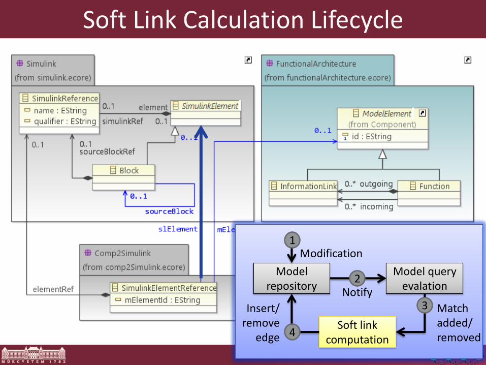
Soft Link Calculation Lifecycle
Model repository
Model query evalation
Modification
Notify
Soft link computation
Match added/ removed
Insert/ remove
edge
1
2
3
4

Traceability in IMA Tools
T
T
T Functional
Architecture Simulink model
Component Library model
Platform Description
model
Legend Model Traceability Traceability references T
Component Library
Simulink model
Functional Architecture
model
T
Allocation Specification
model
Integrated Architecture
Simulink model
T
T

Model driven development of ARINC653 configuration tables

Recent Project
Goal: Allocate SW components to ARINC653 compliant IMA platform
93
Functional Architecture
Platform description
Component database
Allocation
Integrated System Model

Supply fresh air
Supply hot air
Monitor temperature
Set temperature
Designing ARINC653 configurations
Pack
Controller
Zone
Controller
Aft Zone
ForwardZone
Flight DeckAir
Conditioning panel
System Display
Zone Controller
Pack Controller
Pack
Pack
Pack Controller
SW functionality (critical + non-critical)
3
System
Display
AirCond
Panel
3
Redundancy requirement

Job instances, Partitions, Modules
Pack
Controller
Zone
Controller
Aft Zone
ForwardZone
Flight DeckAir
Conditioning panel
System Display
Zone Controller
Pack Controller
Pack
Pack
Pack Controller
SW functionality (critical + non-critical)
3
System
Display
AirCond
Panel
3
1
2 3
7
Job instances
4
5 6
8
Partitions
Modules
Constraints
2
5
3
4
8
8
8
8
Memory needs + constraints
Do not mix critical and non-crit. jobs
Do not mix instances of the same critical job
Additional constraints • WCET, • scheduling, etc. • interfaces • datatypes

Allocating communication channels
Pack
Controller
Zone
Controller
Aft Zone
ForwardZone
Flight DeckAir
Conditioning panel
System Display
Zone Controller
Pack Controller
Pack
Pack
Pack Controller
SW functionality
3
System
Display
AirCond
Panel
3
1
2
3
7
4
5
6
8
Communication channels
Temperature
Pressure
Humidity
Model Driven Development of IMA Configs
Functional Architecture
Platform description
Component database
Allocation
Integrated System Model
Inputs: • Platform Independent Model (PIM) (functional + nonfunc. reqs; Simulink) • Platform Description Model (PDM) for ARINC 653 (DSML)
Output: • Integrated system model • Ready for simulation • End-to-end traceability

Traditional MDA Theory?
Problems:
• Marking is too complex
• Not all MT steps can be automated
98
Platform Independent
Model
Platform description
Marked PIM
Platform Specific Model
Automated Model Transf.
Marking

Model Driven Development of IMA Configs Model transformation chains: • Designer-guided manual steps • Automated steps
• design space exploration • optimization • code generators
• Continuous validation of design rules
Capture constraints
Explore alternatives
Human decision
Automate consequences
Functional Architecture
Platform description
Component database
Allocation
Integrated System Model

Model Driven Development of IMA Configs
Precise development workflow: • Aligned with certification-compliant development process • Monitors design phases
• completed steps • incomplete steps
Functional Architecture
Platform description
Component database
Allocation
Integrated System Model
End-to-end traceability: • Traceability models
• linking FAM and PDM to IAM • integration with requirements tool (e.g. DOORS)
• Soft interconnection of models by incremental model queries

Model transformation approaches

MT: categories
Model-to-Code (M2C)
o Text generation
o AST generation special case of M2M
o Ad-hoc, dedicated, template based, etc.
Model-to-Model (M2M)
o Between models
• Intra-domain transformation
(e.g., simulation, refactoring, validation)
• Inter-domain transformation
(PIM-to-PSM mapping, model analysis)
o Bridging semantical gaps

Model Transformation approaches
Direct Model Manipulation
Relational
Graph Transformation based
Hybrid
Other

Direct Model Manipulation
Models stored in a Model Space
Manipulation through API
Queries hand coded
Examples:
o Base EMF
o Jamda
o SiTra

Relational Approaches
Based on mathematical relations
o Defined as constraints
o Constraint logic programming
Queries captured as constraints
Model manipulation handled by labeling
Fully declarative definition
Example:
o QVT

Graph Transformation based
Model are graphs use Graph Transformation
Declarative definition
Precise formal semantics
Queries as graph patterns
Model manipulation as graph transformation rules
Examples: o AGG
o GreAT
o ATOM

Hybrid approaches
Combines declarative and imperative definition
”Developer friendly”
Typically
o Queries declarative
o Control Structure imperative
Complex language
Largest transformations are using this approach
Example:
o ATL
o Viatra2

Other - XSLT
Models as XMI files
Model Transformation as XSLT programs
Hard to maintain
XMI representations are
o verbose
o poor readability

Implementing a Graph Transformation Engine

Implementing GT engines
Key elements
oModel Store
• Storing typed graphs
• Support easy import and export
o Pattern Matching
• Find match for LHS
o Model manipulation
• Fast model manipulation
• Rollback
• Notification
111
Pattern matching techniques
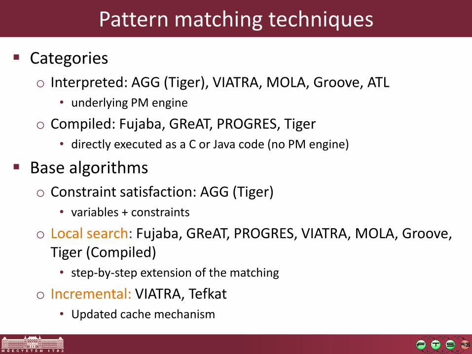
Categories
o Interpreted: AGG (Tiger), VIATRA, MOLA, Groove, ATL • underlying PM engine
o Compiled: Fujaba, GReAT, PROGRES, Tiger • directly executed as a C or Java code (no PM engine)
Base algorithms
o Constraint satisfaction: AGG (Tiger) • variables + constraints
o Local search: Fujaba, GReAT, PROGRES, VIATRA, MOLA, Groove, Tiger (Compiled) • step-by-step extension of the matching
o Incremental: VIATRA, Tefkat • Updated cache mechanism

Constraint satisfaction based Pattern Matching
Realization:
o Nodes are handled as CSP variables
o Constraints derived from edges
o Type information as domain reduction
o Traversal: backtracking algorithm
Pros:
o Adaptive algorithm
Contras:
o Handling large models
o Scalability
113
Method
ousually defined in design/compile time
osimple search plan
ohard wired precedence for constraint checking (NAC, injectivity, attribute, etc.)
Good performance expected when:
oSmall patterns, bound input parameters
Local Search based Pattern Matching

Pattern Matching: Local Search
PM can be the most time-consuming part
Most implementations perform local search
Example: simplified Petri-net firing LHS RHS
Place
Token
Tran. Place a1:inarc a2:outarc
Place
Token
Tran. Place a1:inarc a2:outarc
ttn1:tokens tkn2:tokens
p2
p1
p3
t1
1 2 3
4 Search Plan
p1
p2
p3, t2
p2, t1, p1, k1
p3, t2, p2 p3 t2
p2, t1 p2, t1, p1
Search Space
(Typically depth-first)
1 2 3 4
o Fujaba, GReAT, PROGRES, Groove, Tiger, GrGEN.NET…
o VIATRA2 also has a LS-based pattern matcher
o Good performance expected:
o Small patterns, bound input parameters

115
Goal o Store matching sets o Incremental update o Fast response
Good performance expected when: o frequent pattern matching o Small updates
Possible application domain o E.g. synchronization, constraints, model simulation,
etc.
Example implementation (VIATRA): an adapted RETE algorithm
Incremental Pattern Matching

Incremental Pattern Matching by RETE
p2
p1
p3
HOST
Place
t2
Transition Token
t1
k2 k1
k2 k1
p1 p2 t2 t1
p3, k2 p1, k1
p3, k2, t3
p1, k1, t1, p2
t3 t3
t3
p1 p2 p3 t2 t1
t3
t3
p1, k1, t1
p3, k2, t2, p1
p3
t3
p3, k2, t3
RETE net
o node: (sub)pattern
o edge: change propagation
Demostrating the principle
o input: Petri-net
o pattern: fireable transition
o change: new transition
Input nodes
Intermediate nodes
Production node
Model / host graph

117
Hybrid pattern matching
Combine local search-based and incremental pattern matching
Motivation
o Incremental PM is better for most cases, but…
• Has memory overhead!
• Has update overhead
o LS might be better in certain cases
• Memory consumption (cache size)
• Cache construction time penalty (overhead, simple navigation patterns)
• Expensive updates (e.g., move operation)

Modeltransformation engine
Modeling framework
Source model
Source language
Target- model
Target- language
MT rule
MT engine
Our research: Design and analysis of modeltransformation
• Mathematically precise + intuitive MT language
• Reusable MT components
Specification of
Modeltransformation • Effective and interactive
design methods
• Support for Domain experts work
Design of
Modeltransformation
• Effective runtime performance
• >1 million model element
• IDE integration
Application of
Modeltransformation
• Mathematical Precision
• Verification and Validation techniques
Verification of
Modeltransformation