Embed Size (px)
Citation preview
841 © 2012 ISIJ
ISIJ International, Vol. 52 (2012), No. 5, pp. 841–849
Fountain Pyrometer for Strip Temperature Measurement in Cooling Banks of a Hot Strip Mill
Tatsuro HONDA,1) Chihiro UEMATSU,1) Hisayoshi TACHIBANA,1) Shigemasa NAKAGAWA,1) Yasuhiko BUEI,2) Kouichi SAKAGAMI,2) Kazuyoshi KIMURA2) and Hideyuki TAKAHASHI2)
1) Sumitomo Metal Industries, Ltd., Corporate Research and Development Laboratories, 1-8 Fusocho Amagasaki Hyogo, 660-0891Japan. E-mail: [email protected], [email protected], [email protected], [email protected] 2) Sumitomo Metal Industries, Ltd., Steel Sheet, Plate, Titanium &Structural Steel Company, 3 Hikari Kashima Ibaraki, 314-0014 Japan. E-mail: [email protected], [email protected], [email protected], [email protected]
(Received on August 30, 2011; accepted on November 17, 2011; originally published in Tetsu-to-Hagané,Vol. 96, 2010, No. 10, pp. 592–600)
Sumitomo Metal Industries, Ltd. (SMI) has developed a new temperature measurement method(Fountain pyrometer) and an associated control system, for hot strip cooled by water in cooling banks.
High tensile steel is seeing increasing use in lightweight cars to improve fuel economy and reduce CO2
emissions. Reliable material quality of hot strip products, including high tensile steel, requires good tem-perature control on the run-out table. The conventional control method is not good enough because thetemperature of a hot strip cannot be accurately measured in the cooling banks, where the cooling waterinterferes with thermal radiation from the hot strip surface.
SMI has developed the Fountain pyrometer, which uses a water purge to stabilize the passage of ther-mal radiation from the hot strip surface. Experiment confirms that Fountain pyrometers can reliably mea-sure hot strip temperatures above 360 degrees Centigrade even in cooling banks with a great deal ofcooling water. The response time of Fountain pyrometers is 10 or 20 ms. SMI has also developed a newcontrol system using Fountain pyrometers, a combination that allows very precise temperature control ofhot strip on the run-out table.
KEY WORDS: temperature measurement; pyrometer; hot strip; coiling temperature; run-out table; highstrength steel.
1. Introduction
Light-weight cars are gaining importance as a counter-measure for global warming, and this has increased thedemand for high tensile steel as an automotive material.However, important properties of high tensile hot strip,including its tensile strength, depend strongly on its tem-perature during the cooling process on the run-out table inthe hot strip mill. Accurate temperature control at this stagejust before coiling is thus quite important, and some workin this area has been reported.1–6) Generally and conven-tionally, control systems have used pyrometers installedoutside of cooling banks on the run-out table, and appliedtheir output to calculating a strip temperature predic-tion.1,4,5) However, prediction failures involving the heattransfer rate between the hot strip and cooling water havebeen a significant problem. Particularly in the case of hightensile steel, the boiling regime of the cooling water tendsto change from film boiling to transition boiling becausethe coiling temperature is low, and then the heat transferrate changes suddenly to make predictability difficult. Theprediction failure causes the coiling temperature to fall outof the target range.
To solve this problem, the authors have developed a newtemperature measurement tool called “Fountain pyrome-ter”,7,8) which makes an accurate strip temperature measure-ment possible even when the cooling banks contain largeamounts of cooling water.7,8) We have also developed a newcoiling temperature control method using the Fountainpyrometer.9) These developments allow the temperature ofhot strip to be measured directly and permit the accuratecontrol of coiling temperature even at a low coiling temper-ature.
In this paper we introduce the Fountain pyrometer andevaluate its online accuracy together with the new controlsystem in five chapters.
Chapter two covers the cooling equipment of the KashimaSteel Works hot strip mill run-out table, and temperaturemeasurement problems in the cooling banks. Chapter threeshows how the Fountain pyrometer solved these problems.Chapter four examines the accuracy of the Fountain pyrom-eter. Chapter five explores the application of feed-forwardcontrol using Fountain pyrometers in the hot strip mill ofKashima Steel Works.
© 2012 ISIJ 842
ISIJ International, Vol. 52 (2012), No. 5
2. Target Facility and Problems of the ConventionalMethod
2.1. Target FacilityA diagram of the run-out table of the hot strip mill at
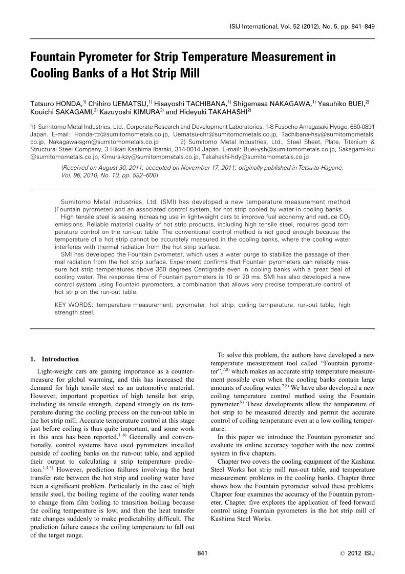
Kashima Steel Works, including its cooling equipment andpyrometers, is shown in Fig. 1. After a hot strip is rolled bythe finisher, it is cooled to the target coiling temperature bythe cooling equipment in the run-out table, and is coiled bythe coiler. Figure 2 shows a vertical section view of thecooling bank, parallel to the strip motion, and the construc-tion of the ON/OFF control valves. Each cooling bank of therun-out table consists of many cooling headers that areinstalled over and under the pass-line and appear as down-stream parts below the ON/OFF valves. These valves areoperated by the coiling temperature controller. There are 6cooling banks in the upstream cooling zone of the run-outtable and 10 cooling banks downstream.
As shown in Fig. 1, pyrometers are used in the conven-tional temperature measurement system. The first one is justafter the finisher, and both it and its output are referred tothe finishing temperature (FT). The second one lies betweentwo cooling zones, and both it and its output are referred toas intermediate temperature (IT). The third one, coiling tem-perature (CT) is placed just ahead of coiling. Output fromthese pyrometers is used for coiling temperature control.3,4)
Conventionally, these pyrometers are installed at positionsoutside of the cooling banks where there is little coolingwater. An air jet (air purge) along and around the pyrome-ter’s view axis prevents water drops and dust from blockingthe view. This obtains stable measurements of hot strip tem-peratures, but only outside of the cooling banks.
2.2. Conventional Coiling Temperature ControlConventional coiling temperature control has been done
in the following way. The temperature drop of the hot stripbetween IT and CT can be determined from measured ITand aim coiling temperature (CTaim). From this temperaturedrop, the required amount of cooling water can be calculatedusing a prediction model and the number of valves to opencan be decided.
When hot strip temperature is predicted with a model, thecalculated temperature depends mainly on the heat transferrate between the cooling water and the hot strip surface, soit is necessary to estimate the heat transfer rate with highaccuracy. Therefore, a method has been developed to revisethe heat transfer rate based on information, which caninclude hot strip temperature, speed, amount of coolingwater and water temperature. But when producing high ten-sile steel, because its coiling temperature is generally com-paratively low, the boiling regime of cooling water tends tobe transition boiling. During transition boiling, the heattransfer rate between the cooling water and the hot strip sur-face can change suddenly and dramatically, making it verydifficult to estimate the heat transfer rate with high accuracy.A large change in the heat transfer rate produces a largechange in the temperature of the hot strip, causing the coil-ing temperature to fall outside the target temperature range.Efficient production thus requires more accurate control ofthe coiling temperature.
2.3. Problems Measuring Hot Strip Temperature in theCooling Banks
It is difficult to measure the temperature of a hot stripwhile it is in a cooling bank of a run-out table. First, the hotstrip sometimes runs at 25 m/second. In addition, the headof the running hot strip often moves up and down. So onlya non-contact device like a pyrometer should be used, orthere could be destructive collisions.
However, the large amount of cooling water interfereswith pyrometer measurements. Figure 3 shows photographsof the variety of cooling water applications in and around
Fig. 1. Run-out table and pyrometers in a hot strip mill.
Fig. 2. Top and bottom cooling headers. Fig. 3. Measurement condition of cooling banks.
ISIJ International, Vol. 52 (2012), No. 5
843 © 2012 ISIJ
the cooling banks. In Fig. 3(a), laminar cooling water flowsdown from the top cooling headers to the hot strip top sur-face. In Figs. 3(b) and 3(c), sprays apply water from the bot-tom cooling headers to the bottom surface of hot strip andprovide water to cool the roll. Also, some water, includingair bubbles, drifts onto top surface of the hot strip. Figure3(c) shows how a large amount of cooling water from thebottom cooling header was atomized, scattering like fogeven to the outside of the cooling banks and blocking theview of the hot strip. A pyrometer can only detect thermalradiation from a target, and calculate the temperature fromthat, but little useful information can penetrate such a fog.Worse, the interference fluctuates in such a way that eventime-averaging fails to provide a sufficiently accurate read-ing.
3. The Newly Developed Temperature MeasurementMethod (Fountain Pyrometer)
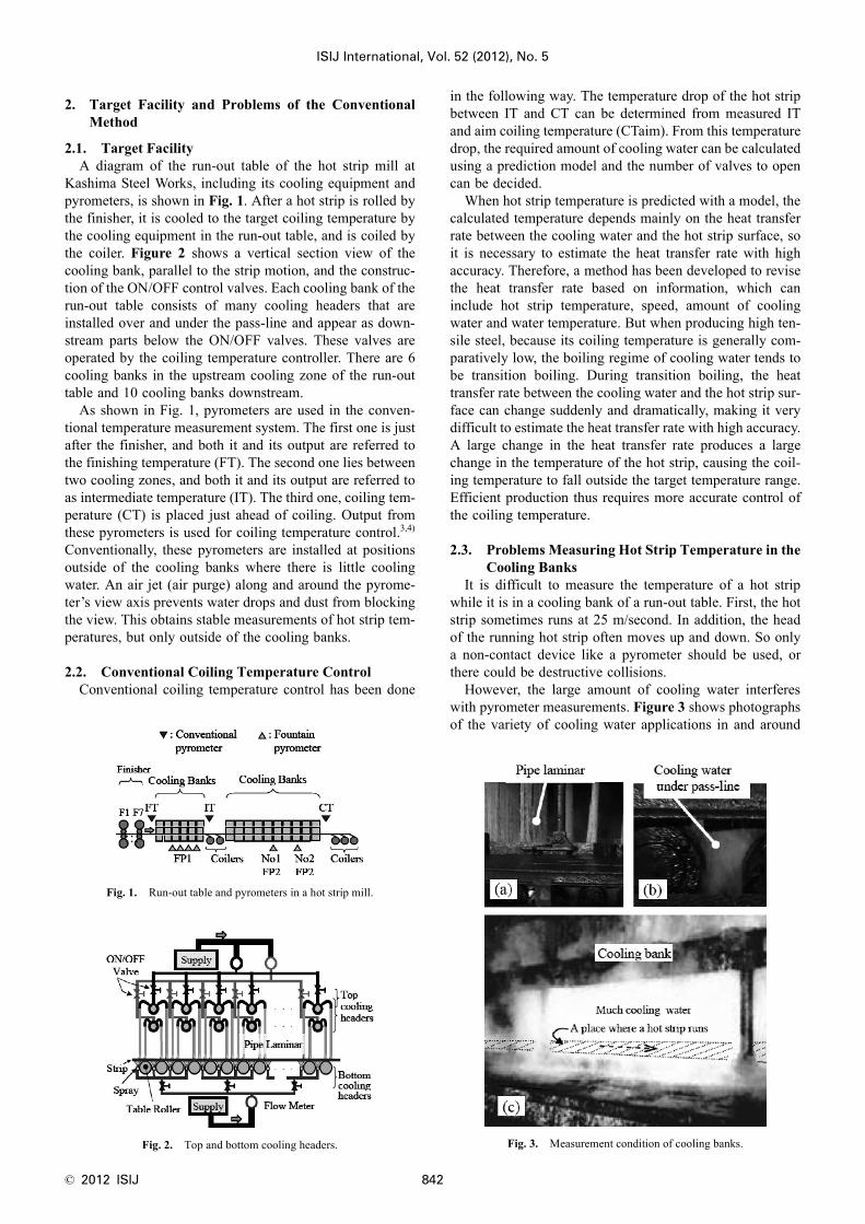
3.1. The Setup of the Fountain PyrometerFigure 4 shows the new Fountain pyrometer. Its sensor
head is installed under the pass line, and purge waterstreams from the nozzle of the sensor head. Thermal radia-tion from the hot strip follows an optical path through thepurge water, an optical fiber and optical filter, then is ana-lyzed using Plank’s radiation law, as in a conventionalpyrometer.
The specifications of Fountain pyrometers are shown inTable 1. With a response time of 10 to 20 ms, they can mea-sure hot strip temperatures from 360 to 1 200°C by usingtwo different pyrometers.
3.2. The Principle of the Fountain PyrometerFigure 5 summarizes the challenges of temperature mea-
surement in the environment of a hot strip mill. Light scat-tering and absorption by water droplets impair the functionof a pyrometer. Jets of air or water may clear some of thedroplets from the pyrometer’s optical path and reduce thisproblem. However, a strong jet with a large core and highspeed would be needed to clear enough water drops from thepath to the pyrometer.10) Such a strong purge would cool thetarget surface significantly at the measuring point, impairingthe pyrometer’s reliability and introducing a cooling error.
Such a strong purge might even obstruct the stable run-ning of the hot strip. When a strong purge is applied, itshould neither disturb the cooling nor obstruct the stablerunning of the hot strip.
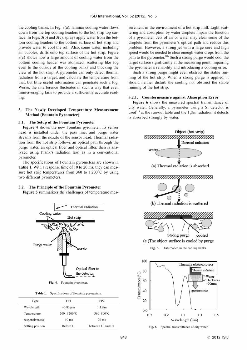
3.2.1. Countermeasure against Absorption ErrorFigure 6 shows the measured spectral transmittance of
city water. Generally, a pyrometer using a Si detector isused11) at the run-out table and the 1 μm radiation it detectsis absorbed strongly by water.
Fig. 4. Fountain pyrometer.
Table 1. Specifications of Fountain pyrometers.
Type FP1 FP2
Wavelength ~0.83 μ m 1.1 μ m
Temperature 500–1 200°C 360–800°C
responsiveness 10 ms 20 ms
Setting position Before IT between IT and CT
Fig. 5. Disturbance in the cooling banks.
Fig. 6. Spectral transmittance of city water.
© 2012 ISIJ 844
ISIJ International, Vol. 52 (2012), No. 5
However, wavelengths shorter than 0.9 μm show hightransmittance even through 50 mm thickness of water. Inthis wavelength range, as the wavelength shortens, the trans-mittance rises. However, at shorter wavelengths the intensi-ty of thermal radiation decreases sharply, so a pyrometer’slow-temperature measurement limit rises. To measure thehot strip temperature between FT and IT, the low-tempera-ture limit should be about 500°C, requiring a wavelengthrange shorter than 0.83 μm.
There is relatively high transmittance in the vicinity of 1.1μ m. Between IT and CT, accurate readings near 400°C arerequired to control the coiling temperature of high tensilesteel, but material at this temperature radiates very little atwavelengths shorter than 0.9 μ m, making the needed mea-surements impossible. The wavelength range to measure hotstrip at 400°C must be around 1.1 μ m.
Two types of Fountain pyrometers have been developedto detect thermal radiation in the two wavelength ranges,and are used to reduce the absorption error caused by water.
3.2.2. Countering ScatteringEven if a pyrometer could detect thermal radiation with-
out absorption error by the intervening water in its opticalpath, scattering by many small droplets would remain aproblem.
As a countermeasure against scattering error, the authorsworked with the idea that the hot strip has the same approx-imate temperature in a wide area around the measurementposition, and scattering error could be usefully reduced ifjust the smallest required area of a pyrometer’s view couldbe made stable for measurement. Although the optical pathof a pyrometer’s view is bent by water drops near the targetsurface, the bent optical path is likely to reach a thermallysimilar nearby point on the hot strip, minimizing measure-ment instability.
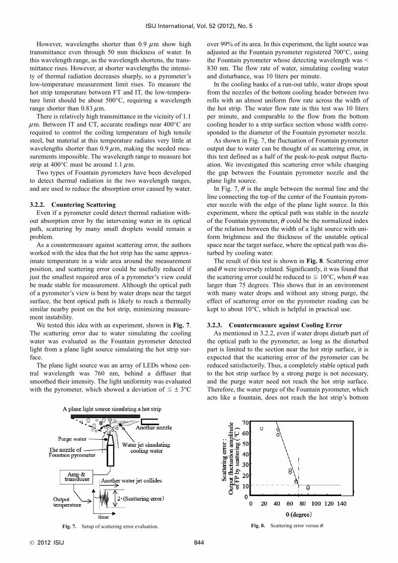
We tested this idea with an experiment, shown in Fig. 7.The scattering error due to water simulating the coolingwater was evaluated as the Fountain pyrometer detectedlight from a plane light source simulating the hot strip sur-face.
The plane light source was an array of LEDs whose cen-tral wavelength was 760 nm, behind a diffuser thatsmoothed their intensity. The light uniformity was evaluatedwith the pyrometer, which showed a deviation of ≦ ± 3°C
over 99% of its area. In this experiment, the light source wasadjusted as the Fountain pyrometer registered 700°C, usingthe Fountain pyrometer whose detecting wavelength was <830 nm. The flow rate of water, simulating cooling waterand disturbance, was 10 liters per minute.
In the cooling banks of a run-out table, water drops spoutfrom the nozzles of the bottom cooling header between tworolls with an almost uniform flow rate across the width ofthe hot strip. The water flow rate in this test was 10 litersper minute, and comparable to the flow from the bottomcooling header to a strip surface section whose width corre-sponded to the diameter of the Fountain pyrometer nozzle.
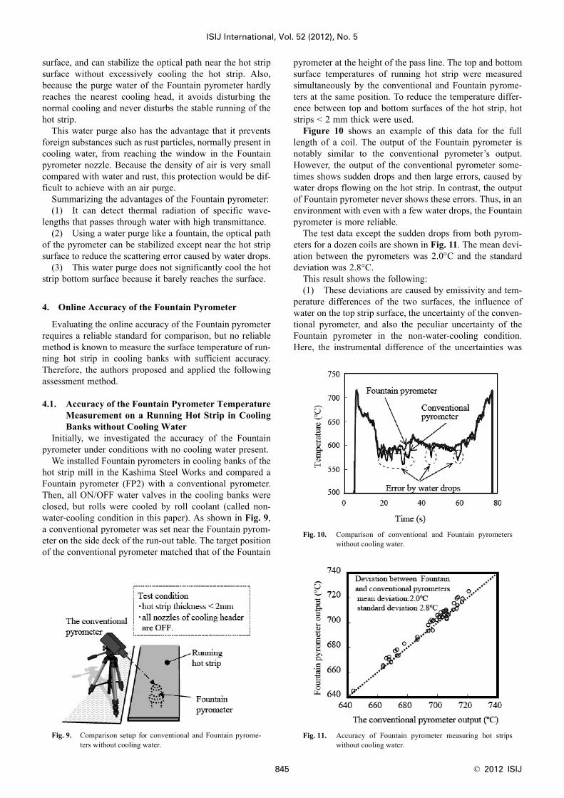
As shown in Fig. 7, the fluctuation of Fountain pyrometeroutput due to water can be thought of as scattering error, inthis test defined as a half of the peak-to-peak output fluctu-ation. We investigated this scattering error while changingthe gap between the Fountain pyrometer nozzle and theplane light source.
In Fig. 7, θ is the angle between the normal line and theline connecting the top of the center of the Fountain pyrom-eter nozzle with the edge of the plane light source. In thisexperiment, where the optical path was stable in the nozzleof the Fountain pyrometer, θ could be the normalized indexof the relation between the width of a light source with uni-form brightness and the thickness of the unstable opticalspace near the target surface, where the optical path was dis-turbed by cooling water.
The result of this test is shown in Fig. 8. Scattering errorand θ were inversely related. Significantly, it was found thatthe scattering error could be reduced to ≦ 10°C, when θ waslarger than 75 degrees. This shows that in an environmentwith many water drops and without any strong purge, theeffect of scattering error on the pyrometer reading can bekept to about 10°C, which is helpful in practical use.
3.2.3. Countermeasure against Cooling ErrorAs mentioned in 3.2.2, even if water drops disturb part of
the optical path to the pyrometer, as long as the disturbedpart is limited to the section near the hot strip surface, it isexpected that the scattering error of the pyrometer can bereduced satisfactorily. Thus, a completely stable optical pathto the hot strip surface by a strong purge is not necessary,and the purge water need not reach the hot strip surface.Therefore, the water purge of the Fountain pyrometer, whichacts like a fountain, does not reach the hot strip’s bottom
Fig. 7. Setup of scattering error evaluation. Fig. 8. Scattering error versus θ.
ISIJ International, Vol. 52 (2012), No. 5
845 © 2012 ISIJ
surface, and can stabilize the optical path near the hot stripsurface without excessively cooling the hot strip. Also,because the purge water of the Fountain pyrometer hardlyreaches the nearest cooling head, it avoids disturbing thenormal cooling and never disturbs the stable running of thehot strip.
This water purge also has the advantage that it preventsforeign substances such as rust particles, normally present incooling water, from reaching the window in the Fountainpyrometer nozzle. Because the density of air is very smallcompared with water and rust, this protection would be dif-ficult to achieve with an air purge.
Summarizing the advantages of the Fountain pyrometer:(1) It can detect thermal radiation of specific wave-
lengths that passes through water with high transmittance.(2) Using a water purge like a fountain, the optical path
of the pyrometer can be stabilized except near the hot stripsurface to reduce the scattering error caused by water drops.
(3) This water purge does not significantly cool the hotstrip bottom surface because it barely reaches the surface.
4. Online Accuracy of the Fountain Pyrometer
Evaluating the online accuracy of the Fountain pyrometerrequires a reliable standard for comparison, but no reliablemethod is known to measure the surface temperature of run-ning hot strip in cooling banks with sufficient accuracy.Therefore, the authors proposed and applied the followingassessment method.
4.1. Accuracy of the Fountain Pyrometer TemperatureMeasurement on a Running Hot Strip in CoolingBanks without Cooling Water
Initially, we investigated the accuracy of the Fountainpyrometer under conditions with no cooling water present.
We installed Fountain pyrometers in cooling banks of thehot strip mill in the Kashima Steel Works and compared aFountain pyrometer (FP2) with a conventional pyrometer.Then, all ON/OFF water valves in the cooling banks wereclosed, but rolls were cooled by roll coolant (called non-water-cooling condition in this paper). As shown in Fig. 9,a conventional pyrometer was set near the Fountain pyrom-eter on the side deck of the run-out table. The target positionof the conventional pyrometer matched that of the Fountain
pyrometer at the height of the pass line. The top and bottomsurface temperatures of running hot strip were measuredsimultaneously by the conventional and Fountain pyrome-ters at the same position. To reduce the temperature differ-ence between top and bottom surfaces of the hot strip, hotstrips < 2 mm thick were used.
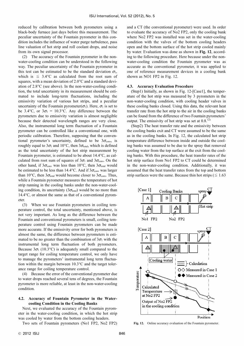
Figure 10 shows an example of this data for the fulllength of a coil. The output of the Fountain pyrometer isnotably similar to the conventional pyrometer’s output.However, the output of the conventional pyrometer some-times shows sudden drops and then large errors, caused bywater drops flowing on the hot strip. In contrast, the outputof Fountain pyrometer never shows these errors. Thus, in anenvironment with even with a few water drops, the Fountainpyrometer is more reliable.
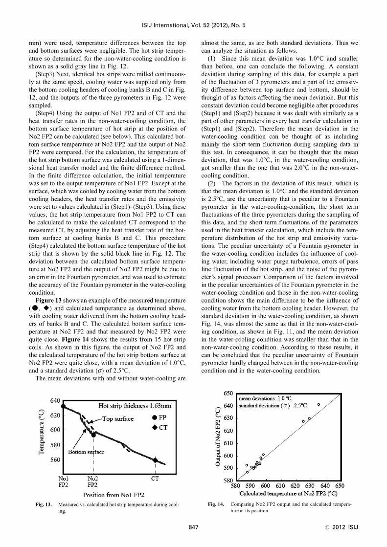
The test data except the sudden drops from both pyrom-eters for a dozen coils are shown in Fig. 11. The mean devi-ation between the pyrometers was 2.0°C and the standarddeviation was 2.8°C.
This result shows the following:(1) These deviations are caused by emissivity and tem-
perature differences of the two surfaces, the influence ofwater on the top strip surface, the uncertainty of the conven-tional pyrometer, and also the peculiar uncertainty of theFountain pyrometer in the non-water-cooling condition.Here, the instrumental difference of the uncertainties was
Fig. 9. Comparison setup for conventional and Fountain pyrome-ters without cooling water.
Fig. 10. Comparison of conventional and Fountain pyrometerswithout cooling water.
Fig. 11. Accuracy of Fountain pyrometer measuring hot stripswithout cooling water.
© 2012 ISIJ 846
ISIJ International, Vol. 52 (2012), No. 5
reduced by calibration between both pyrometers using ablack-body furnace just days before this measurement. Thepeculiar uncertainty of the Fountain pyrometer in this con-dition includes the influence of water purge turbulence, passline valuation of hot strip and roll coolant drops, and noisefrom its own signal processor.
(2) The accuracy of the Fountain pyrometer in the non-water-cooling condition can be understood in the followingway. The peculiar uncertainty of the Fountain pyrometer inthis test can be estimated to be the standard deviation σ1,which is ≦ 3.4°C as calculated from the root sum ofsquares, with a mean deviation of 2.0°C and a standard devi-ation of 2.8°C (see above). In the non-water-cooling condi-tion, the total uncertainty in its measurement should be esti-mated to include long-term fluctuations, including theemissivity variation of various hot strips, and a peculiaruncertainty of the Fountain pyrometer(σ1). Here, σ1 is set tobe 3.4°C, or 3σ1 = 10.3°C. Any difference between thepyrometers due to emissivity variation is almost negligiblebecause their detected wavelength ranges are very close.Also, the instrumental long term fluctuation of a Fountainpyrometer can be controlled like a conventional one, withperiodic calibration. Therefore, supposing that the conven-tional pyrometer’s uncertainty, defined to be 3σconv, isroughly equal to 3σ1 and 10°C, then 3σ total, which is definedas the total uncertainty of the hot strip measurement byFountain pyrometer, is estimated to be about 14.4°C, as cal-culated from root sum of squares of 3σ1 and 3σconv. On theother hand, if 3σconv was less than 10°C, then 3σ total wouldbe estimated to be less than 14.4°C. And if 3σconv was largerthan 10°C, then 3σ total would become closer to 3σconv. Thus,while a Fountain pyrometer measures the temperature of hotstrip running in the cooling banks under the non-water-cool-ing condition, its uncertainty (3σ total) would be no more than14.4°C, or almost the same as that of a conventional pyrom-eter.
(3) When we use Fountain pyrometers in coiling tem-perature control, the total uncertainty, mentioned above, isnot very important. As long as the difference between theFountain and conventional pyrometers is small, coiling tem-perature control using Fountain pyrometers can be mademore accurate. If the emissivity error for both pyrometers isalmost the same, the difference between pyrometers is esti-mated to be no greater than the combination of 3σ1 with theinstrumental long term fluctuation of both pyrometers.Because 3σ1 (10.3°C) is adequately small compared to thetarget range for coiling temperature control, we only haveto manage the pyrometers’ instrumental long term fluctua-tion within the margin between 10.3°C and the target toler-ance range for coiling temperature control.
(4) Because the error of the conventional pyrometer dueto water drops reached several tens of degrees, the Fountainpyrometer is more reliable, at least in the non-water-coolingcondition.
4.2. Accuracy of Fountain Pyrometer in the Water-cooling Condition in the Cooling Banks
Next, we evaluated the accuracy of the Fountain pyrom-eter in the water-cooling condition, in which the hot stripwas cooled by water from the bottom cooling headers.
Two sets of Fountain pyrometers (No1 FP2, No2 FP2)
and a CT (the conventional pyrometer) were used. In orderto evaluate the accuracy of No2 FP2, only the cooling bankwhere No2 FP2 was installed was set in the water-coolingcondition with the valves of the bottom cooling headersopen and the bottom surface of the hot strip cooled mainlyby water. Evaluation was done as shown in Fig. 12, accord-ing to the following procedure. Here because under the non-water-cooling condition the Fountain pyrometer was asaccurate as the conventional pyrometer, it was applied toone of reference measurement devices in a cooling bankshown as NO1 FP2 in Fig. 12.
4.3. Accuracy Evaluation Procedure(Step1) Initially, as shown in Fig. 12-[Case1], the temper-
ature of the hot strip was measured by 3 pyrometers in thenon-water-cooling condition, with cooling header valves inthese cooling banks closed. Using this data, the relevant heattransfer rate from the hot strip to the air in the cooling bankscan be found from the difference of two Fountain pyrometers’output. The emissivity of hot strip was set at 0.8.12)
(Step2) The heat transfer rate and the emissivity betweenthe cooling banks exit and CT were assumed to be the sameas in the cooling banks. In Fig. 12, the calculated hot striptemperature difference between inside and outside the cool-ing banks was assumed to be due to the spray that removedcooling water from the top surface at the exit from the cool-ing banks. With this procedure, the heat transfer rates of thehot strip surface from No1 FP2 to CT could be determinedin the non-water-cooling condition. Additionally, it wasassumed that the heat transfer rates from the top and bottomstrip surfaces were the same. Because thin hot strips (≦ 1.63
Fig. 12. Online accuracy evaluation of the Fountain pyrometer.
ISIJ International, Vol. 52 (2012), No. 5
847 © 2012 ISIJ
mm) were used, temperature differences between the topand bottom surfaces were negligible. The hot strip temper-ature so determined for the non-water-cooling condition isshown as a solid gray line in Fig. 12.
(Step3) Next, identical hot strips were milled continuous-ly at the same speed, cooling water was supplied only fromthe bottom cooling headers of cooling banks B and C in Fig.12, and the outputs of the three pyrometers in Fig. 12 weresampled.
(Step4) Using the output of No1 FP2 and of CT and theheat transfer rates in the non-water-cooling condition, thebottom surface temperature of hot strip at the position ofNo2 FP2 can be calculated (see below). This calculated bot-tom surface temperature at No2 FP2 and the output of No2FP2 were compared. For the calculation, the temperature ofthe hot strip bottom surface was calculated using a 1-dimen-sional heat transfer model and the finite difference method.In the finite difference calculation, the initial temperaturewas set to the output temperature of No1 FP2. Except at thesurface, which was cooled by cooling water from the bottomcooling headers, the heat transfer rates and the emissivitywere set to values calculated in (Step1)–(Step3). Using thesevalues, the hot strip temperature from No1 FP2 to CT canbe calculated to make the calculated CT correspond to themeasured CT, by adjusting the heat transfer rate of the bot-tom surface at cooling banks B and C. This procedure(Step4) calculated the bottom surface temperature of the hotstrip that is shown by the solid black line in Fig. 12. Thedeviation between the calculated bottom surface tempera-ture at No2 FP2 and the output of No2 FP2 might be due toan error in the Fountain pyrometer, and was used to estimatethe accuracy of the Fountain pyrometer in the water-coolingcondition.
Figure 13 shows an example of the measured temperature(●, ◆) and calculated temperature as determined above,with cooling water delivered from the bottom cooling head-ers of banks B and C. The calculated bottom surface tem-perature at No2 FP2 and that measured by No2 FP2 werequite close. Figure 14 shows the results from 15 hot stripcoils. As shown in this figure, the output of No2 FP2 andthe calculated temperature of the hot strip bottom surface atNo2 FP2 were quite close, with a mean deviation of 1.0°C,and a standard deviation (σ) of 2.5°C.
The mean deviations with and without water-cooling are
almost the same, as are both standard deviations. Thus wecan analyze the situation as follows.
(1) Since this mean deviation was 1.0°C and smallerthan before, one can conclude the following. A constantdeviation during sampling of this data, for example a partof the fluctuation of 3 pyrometers and a part of the emissiv-ity difference between top surface and bottom, should bethought of as factors affecting the mean deviation. But thisconstant deviation could become negligible after procedures(Step1) and (Step2) because it was dealt with similarly as apart of other parameters in every heat transfer calculation in(Step1) and (Step2). Therefore the mean deviation in thewater-cooling condition can be thought of as includingmainly the short term fluctuation during sampling data inthis test. In consequence, it can be thought that the meandeviation, that was 1.0°C, in the water-cooling condition,got smaller than the one that was 2.0°C in the non-water-cooling condition.
(2) The factors in the deviation of this result, which isthat the mean deviation is 1.0°C and the standard deviationis 2.5°C, are the uncertainty that is peculiar to a Fountainpyrometer in the water-cooling-condition, the short termfluctuations of the three pyrometers during the sampling ofthis data, and the short term fluctuations of the parametersused in the heat transfer calculation, which include the tem-perature distribution of the hot strip and emissivity varia-tions. The peculiar uncertainty of a Fountain pyrometer inthe water-cooling condition includes the influence of cool-ing water, including water purge turbulence, errors of passline fluctuation of the hot strip, and the noise of the pyrom-eter’s signal processor. Comparison of the factors involvedin the peculiar uncertainties of the Fountain pyrometer in thewater-cooling condition and those in the non-water-coolingcondition shows the main difference to be the influence ofcooling water from the bottom cooling header. However, thestandard deviation in the water-cooling condition, as shownFig. 14, was almost the same as that in the non-water-cool-ing condition, as shown in Fig. 11, and the mean deviationin the water-cooling condition was smaller than that in thenon-water-cooling condition. According to these results, itcan be concluded that the peculiar uncertainty of Fountainpyrometer hardly changed between in the non-water-coolingcondition and in the water-cooling condition.
Fig. 13. Measured vs. calculated hot strip temperature during cool-ing.
Fig. 14. Comparing No2 FP2 output and the calculated tempera-ture at its position.
© 2012 ISIJ 848
ISIJ International, Vol. 52 (2012), No. 5
(3) The total uncertainty of the Fountain pyrometerBecause the peculiar uncertainty of Fountain pyrometer
in the water-cooling condition was the same as in the non-water-cooling condition, the total uncertainty of the Fountainpyrometer should also be the same as in the non-water-cool-ing condition, so the 3σ total of the Fountain pyrometer in thewater-cooling-condition is ≦ 14.4°C, or essentially thesame as conventional pyrometers like those installed outsideof the cooling banks.
(4) The Fountain pyrometer was confirmed to be suffi-ciently accurate for coiling temperature control, both withand without cooling water.
5. Online Coiling Temperature Control Using theFountain Pyrometer
5.1. Outline of Coiling Temperature Control Using theFountain Pyrometer
The authors have installed Fountain pyrometers in thecooling banks of the Kashima hot strip mill, as shown inFig. 1, and have developed a coiling temperature controlsystem.9) A hot strip was considered to be divided into con-stant length sections, so the temperature of each sectioncould be individually monitored and controlled. Initially,based on the target coiling temperature and using a temper-ature prediction model similar to the conventional control,the required amount of cooling water and the banks whereit should be applied were determined. When a Fountainpyrometer output different temperature from the predictedone at some section of the hot strip, the cooling beyond thatpoint where it was installed was modified to correct the dis-crepancy. That is a feed-forward control system using Foun-tain pyrometers.
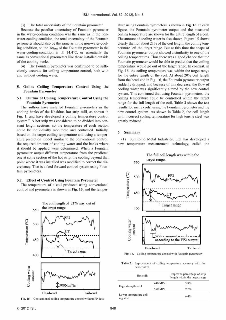
5.2. Effect of Control Using Fountain PyrometerThe temperature of a coil produced using conventional
control and pyrometers is shown in Fig. 15, and the temper-
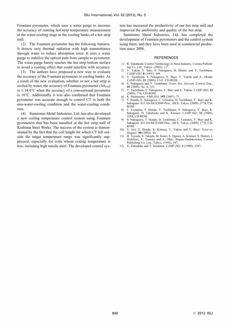
ature using Fountain pyrometers is shown in Fig. 16. In eachfigure, the Fountain pyrometer output and the measuredcoiling temperature are shown for the entire length of a coil.The amount of cooling water is also shown. Figure 15 showsclearly that for about 21% of the coil length, the coiling tem-perature left the target range. But at this time the shape ofFountain pyrometer output showed a similarity to one of thecoiling temperatures. Thus there was a good chance that theFountain pyrometer would be able to predict that the coilingtemperature would go out of the target range. In contrast, inFig. 16, the coiling temperature was within the target rangefor the entire length of the coil. At about 20% coil lengthfrom the head-end in Fig. 16, the Fountain pyrometer outputsuddenly dropped, and because of this decrease, the flow ofcooling water was significantly altered by the new controlsystem. This confirmed that using Fountain pyrometers, thecoiling temperature could be controlled within the targetrange for the full length of the coil. Table 2 shows the testresults for many coils, using the Fountain pyrometer and thenew control system. As shown in Table 2, the coil lengthwith incorrect coiling temperature for high tensile steel wasgreatly reduced.
6. Summary
(1) Sumitomo Metal Industries, Ltd. has developed anew temperature measurement technology, called the
Fig. 15. Conventional coiling temperature control without FP data.
Fig. 16. Coiling temperature control with Fountain pyrometer.
Table 2. Improvement of coiling temperature accuracy with thenew control.
Hot coils Improved percentage of strip length within the target range
High strength steel440 MPa 5.8%
590 MPa 9.7%
Lower temperature coil-ing steel 6.4%
ISIJ International, Vol. 52 (2012), No. 5
849 © 2012 ISIJ
Fountain pyrometer, which uses a water purge to increasethe accuracy of running hot strip temperature measurementat the water-cooling stage in the cooling banks of a hot stripmill.
(2) The Fountain pyrometer has the following features.It detects only thermal radiation with high transmittancethrough water to reduce absorption error. It uses a waterpurge to stabilize the optical path from sample to pyrometer.The water purge barely reaches the hot strip bottom surfaceto avoid a cooling effect that could interfere with accuracy.
(3) The authors have proposed a new way to evaluatethe accuracy of the Fountain pyrometer in cooling banks. Asa result of the new evaluation, whether or not a hot strip iscooled by water, the accuracy of Fountain pyrometer (3σ total)is ≦14.4°C when the accuracy of a conventional pyrometeris 10°C. Additionally it was also confirmed that Fountainpyrometer was accurate enough to control CT in both thenon-water-cooling condition and the water-cooling condi-tion.
(4) Sumitomo Metal Industries, Ltd. has also developeda new coiling temperature control system using Fountainpyrometers that has been installed at the hot strip mill ofKashima Steel Works. The success of the system is demon-strated by the fact that the coil length for which CT fell out-side the target temperature range was significantly sup-pressed, especially for coils whose coiling temperature islow, including high tensile steel. The developed control sys-
tem has increased the productivity of our hot strip mill andimproved the uniformity and quality of the hot strip.
Sumitomo Metal Industries, Ltd. has completed thedevelopment of Fountain pyrometers and the control systemusing them, and they have been used in commercial produc-tion since 2008.
REFERENCES
1) R. Takahashi: Control Technology in Steel Industry, Corona Publish-ing Co. Ltd., Tokyo, (2002), 117.
2) Y. Yakita, Y. Sato, S. Nakagawa, H. Shimiz and Y. Tachibana:CAMP-ISIJ, 8 (1995), 449.
3) Y. Tachibana, S. Nakagawa, Y. Buei, Y. Yakita and A. Okada:CAMP-ISIJ, 21 (2008), 1141, CD-ROM.
4) S. Nakagawa and Y. Tachibana: Trans. Soc. Instrum. Control Eng.,45 (2009), No. 4, 233.
5) Y. Tachibana, S. Nakagawa, Y. Buei and Y. Yakita: CAMP-ISIJ, 22(2009), 574, CD-ROM.
6) K. Hashizume: NMS-ISIJ, 193 (2007), 73.7) T. Honda, S. Nakagawa, C. Uematsu, H. Tachibana, Y. Buei and K.
Sakagami: ICCAS-SICE2009 Proc., SICE, Tokyo, (2009), 2774, CD-ROM.
8) C. Uematsu, T. Honda, Y. Tachibana, S. Nakagawa, Y. Buei, K.Sakagami, H. Takahashi and K. Kimura: CAMP-ISIJ, 22 (2009),1054, CD-ROM.
9) S. Nakagawa, T. Honda, H. Tachibana, C. Uematsu, Y. Buei and K.Sakagami: ICCAS-SICE2009 Proc., SICE, Tokyo, (2009), 2778, CD-ROM.
10) Y. Isei, T. Honda, K. Kimura, Y. Yakita and Y. Buei: Tetsu-to-Hagané, 90 (2004), 40.
11) H. Toyoda, S. Takada, M. Kono, S. Ogawa, A. Kimura, S. Hattori, I.Hishikari, Y. Tamura and A. Ohte: Sinpen-Ondokeisoku, CoronaPublishing Co. Ltd., Tokyo, (1992), 187.
12) Y. Fukudaka and T. Iwamura: CAMP-ISIJ, 1 (1988), 1587.