Embed Size (px)
Citation preview

Doc. Ver. : V2.0
2014.10.23
R&D Center
Union Community Co., Ltd.
Installation & Wiring Guide
Four Door Access Controller
MCP-040 V2.0

1. Power Connector connection
Installation for MCP-040 V2.0
Backup Battery
Interface
BAT(-)
BAT(+)
15V GND
DC 15V 6A
Power Adapter
PWR+ PWR-
12V G 12V G
12V G5V G
GND15V
DC 15V OUTDC 5V OUT
GND5V
GND15V
DC 15V OUT
GND15V
DC 15V OUT
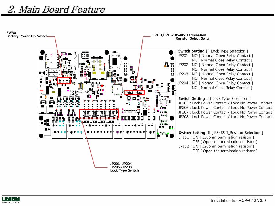
2. Main Board Feature
Switch Setting I [ Lock Type Selection ]JP201 : NO [ Normal Open Relay Contact ]
NC [ Normal Close Relay Contact ]JP202 : NO [ Normal Open Relay Contact ]
NC [ Normal Close Relay Contact ]JP203 : NO [ Normal Open Relay Contact ]
NC [ Normal Close Relay Contact ]JP204 : NO [ Normal Open Relay Contact ]
NC [ Normal Close Relay Contact ]
Switch Setting III [ RS485 T_Resistor Selection ]JP151 : ON [ 120ohm termination resistor ]
OFF [ Open the termination resistor ]JP152 : ON [ 120ohm termination resistor ]
OFF [ Open the termination resistor ]
JP201~JP204JP205~JP208Lock Type Switch
JP151/JP152 RS485 Termination Resistor Select Switch
SW301Battery Power On Switch
Installation for MCP-040 V2.0
Switch Setting II [ Lock Type Selection ]JP205 : Lock Power Contact / Lock No Power Contact JP206 : Lock Power Contact / Lock No Power Contact JP207 : Lock Power Contact / Lock No Power Contact JP208 : Lock Power Contact / Lock No Power Contact

ZO
NE2/Z
ON
E6
ZO
NE3/Z
ON
E7
RD
RA+
15V IN
GN
D
CO
M
NO
/NC LO
CK#1
IN1
IN3
IN4
IN2
GN
D
GN
D
GN
D
GN
D
ZO
NE1/Z
ON
E5
ZO
NE4/Z
ON
E8
GN
D
Eth
ern
et
15V O
UT
5V O
UT
EXPA+
OU
T1
D01
D11
3. Connection of Wires to terminal blocks
D01 D11 OUT1 OUT2
D02 D12 OUT3 OUT4
D03 D13 OUT5 OUT6
D04 D14 OUT7 OUT8PWR+ PWR-
12V G 12V G
12V G5V GNO/NC COM
NO/NC
COMNO/NC COM
NO/NC COM
Z1/Z5
GZ2/Z6
Z3/Z7 G
Z4/Z8
G G RDRA+
BELL+RDRB-
EXPA+
EXPB-
BELL-
IN1 G IN2 IN3 G IN4
15V O
UT
15V O
UT
GN
D
GN
D
GN
D
BELL+
BELL-
EXPB-
RD
RB-
GN
D
GN
D
CO
M
NO
/NC LO
CK#2
CO
M
NO
/NC LO
CK#3
CO
M
NO
/NC LO
CK#4
D03
D13
D02
D12
D04
D14
OU
T2
OU
T3
OU
T4
OUT5
OU
T6
OU
T7
OU
T8
Installation for MCP-040 V2.0
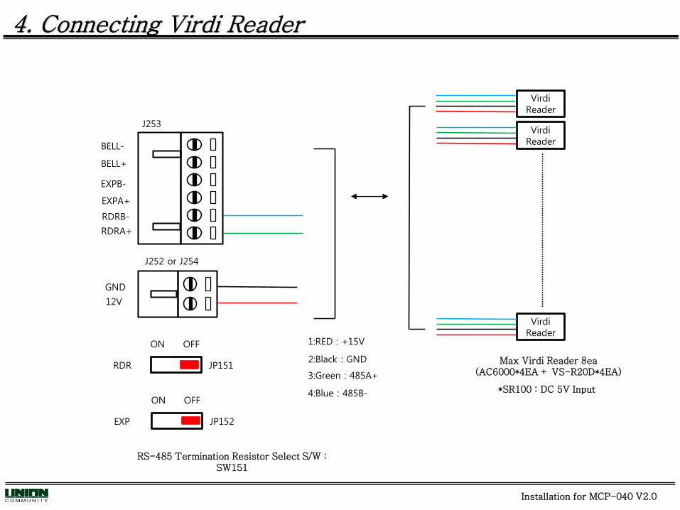
1:RED : +15V
2:Black : GND
3:Green : 485A+
4:Blue : 485B-
RS-485 Termination Resistor Select S/W : SW151
Virdi Reader
Virdi Reader
Virdi Reader
Max Virdi Reader 8ea(AC6000*4EA + VS-R20D*4EA)
4. Connecting Virdi Reader
EXPB-
J253
RDRA+
EXPA+
BELL+
RDRB-
BELL-
12V
GND
J252 or J254
RDR JP151
ON OFF
EXP JP152
ON OFF*SR100 : DC 5V Input
Installation for MCP-040 V2.0

J255
5. Connecting Wiegand Reader
Wiegand Reader1
OUT2
OUT1
D01
OUT4
OUT3
OUT6
OUT5
OUT8
OUT7
12V
GND
J255
J256
J256
J252 or J254
1:RED : +15V2:Black : GND3:Brown : Wiegand IN14:Pink : Wiegand IN05:Green : Buzzer or LED6:Violet : Buzzer or LED
Installation for MCP-040 V2.0
Wiegand Reader2
Wiegand Reader3
Wiegand Reader4
D11
D02
D12
D03
D13
D04
D14
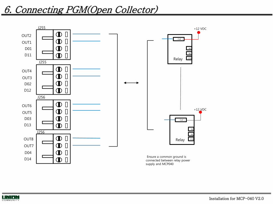
6. Connecting PGM(Open Collector)
- Coil +
NO
NC
COM
- Coil +
NO
NC
COM
+12 VDC
+12 VDC
Relay
Relay
Installation for MCP-040 V2.0
J255
OUT2
OUT1
D01
OUT4
OUT3
OUT6
OUT5
OUT8
OUT7
J255
J256
J256
D11
D02
D12
D03
D13
D04
D14Ensure a common ground is
connected between relay power supply and MCP040

7. Connecting Zone
Installation for MCP-040 V2.0

8. Connecting BELL/Siren
Bell/Siren
Bell Supervision Resistor 2200Ω 5%
EXPB
J253
RDRA
EXPA
BELL+
RDRB
BELL-
Installation for MCP-040 V2.0
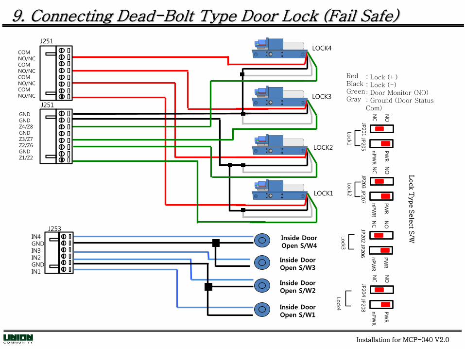
: Lock (+): Lock (-): Door Monitor (NO): Ground (Door Status Com)
J251
RedBlackGreenGray
LOCK4
LOCK3
LOCK2
LOCK1
COMNO/NCCOMNO/NCCOMNO/NCCOMNO/NC
GNDGNDZ4/Z8GNDZ3/Z7Z2/Z6GNDZ1/Z2
Inside DoorOpen S/W3
Inside DoorOpen S/W2
Inside DoorOpen S/W1
Inside DoorOpen S/W4
J253IN4GNDIN3IN2GNDIN1
9. Connecting Dead-Bolt Type Door Lock (Fail Safe)
J251
Installation for MCP-040 V2.0
Lock T
ype S
ele
ct S
/W
Lock
2
NO
NC
JP202
PW
R
nPW
R
JP206
Lock
3
NO
NC
JP203
PW
R
nPW
R
JP207
Lock
4
NO
NC
JP204
PW
R
nPW
R
JP208
Lock
1
NO
NC
JP201
PW
R
nPW
R
JP205
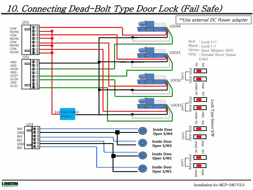
: Lock (+): Lock (-): Door Monitor (NO): Ground (Door Status Com)
J251
RedBlackGreenGray
LOCK4
LOCK3
LOCK2
LOCK1
COMNO/NCCOMNO/NCCOMNO/NCCOMNO/NC
GNDGNDZ4/Z8GNDZ3/Z7Z2/Z6GNDZ1/Z2
Inside DoorOpen S/W3
Inside DoorOpen S/W2
Inside DoorOpen S/W1
Inside DoorOpen S/W4
J253IN4GNDIN3IN2GNDIN1
10. Connecting Dead-Bolt Type Door Lock (Fail Safe)
J251
ExternalPower
(+) (-)
**Use external DC Power adapter
Installation for MCP-040 V2.0
Lock T
ype S
ele
ct S
/W
Lock
2
NO
NC
JP202
PW
R
nPW
R
JP206
Lock
3
NO
NC
JP203
PW
R
nPW
R
JP207
Lock
4
NO
NC
JP204
PW
R
nPW
R
JP208
Lock
1
NO
NC
JP201
PW
R
nPW
R
JP205

: Lock (+): Lock (-): Door Monitor
RedBlackOrange
LOCK4
LOCK3
LOCK2
LOCk1
11. Connecting EM Type Door Lock (Fail Safe)
Inside DoorOpen S/W3
Inside DoorOpen S/W2
Inside DoorOpen S/W1
Inside DoorOpen S/W4
J253IN4GNDIN3IN2GNDIN1
COMNO/NCCOMNO/NCCOMNO/NCCOMNO/NC
GNDGNDZ4/Z8GNDZ3/Z7Z2/Z6GNDZ1/Z2
J251
J251
Installation for MCP-040 V2.0
Lock T
ype S
ele
ct S
/W
Lock
2
NO
NC
JP202
PW
R
nPW
R
JP206
Lock
3
NO
NC
JP203
PW
R
nPW
R
JP207
Lock
4
NO
NC
JP204
PW
R
nPW
R
JP208
Lock
1
NO
NC
JP201
PW
R
nPW
R
JP205

: Lock (+): Lock (-): Door Monitor
RedBlackOrange
LOCK4
LOCK3
LOCK2
LOCk1
12. Connecting EM Type Door Lock (Fail Safe)
Inside DoorOpen S/W3
Inside DoorOpen S/W2
Inside DoorOpen S/W1
Inside DoorOpen S/W4
J253IN4GNDIN3IN2GNDIN1
GNDGNDZ4/Z8GNDZ3/Z7Z2/Z6GNDZ1/Z2
J251
COMNO/NCCOMNO/NCCOMNO/NCCOMNO/NC
J251
ExternalPower
(+) (-)
**Use external DC Power adapter
Installation for MCP-040 V2.0
Lock T
ype S
ele
ct S
/W
Lock
2
NO
NC
JP202
PW
R
nPW
R
JP206
Lock
3
NO
NC
JP203
PW
R
nPW
R
JP207
Lock
4
NO
NC
JP204
PW
R
nPW
R
JP208
Lock
1
NO
NC
JP201
PW
R
nPW
R
JP205

: Lock (+): Lock (-): Door Monitor
13. Connecting Strike Type Door Lock (Fail Safe)
LOCK4
LOCK3
LOCK2
LOCK1
RedBlackOrange
Inside DoorOpen S/W3
Inside DoorOpen S/W2
Inside DoorOpen S/W1
Inside DoorOpen S/W4
J253IN4GNDIN3IN2GNDIN1
COMNO/NCCOMNO/NCCOMNO/NCCOMNO/NC
GNDGNDZ4/Z8GNDZ3/Z7Z2/Z6GNDZ1/Z2
J251
J251
Installation for MCP-040 V2.0
Lock T
ype S
ele
ct S
/W
Lock
2
NO
NC
JP202
PW
R
nPW
R
JP206
Lock
3
NO
NC
JP203
PW
R
nPW
R
JP207
Lock
4
NO
NC
JP204
PW
R
nPW
R
JP208
Lock
1
NO
NC
JP201
PW
R
nPW
R
JP205

: Lock (+): Lock (-): Door Monitor
14. Connecting Strike Type Door Lock (Fail Safe)
LOCK4
LOCK3
LOCK2
LOCK1
RedBlackOrange
Inside DoorOpen S/W3
Inside DoorOpen S/W2
Inside DoorOpen S/W1
Inside DoorOpen S/W4
J253IN4GNDIN3IN2GNDIN1
GNDGNDZ4/Z8GNDZ3/Z7Z2/Z6GNDZ1/Z2
J251
ExternalPower
(+) (-)
COMNO/NCCOMNO/NCCOMNO/NCCOMNO/NC
J251**Use external DC Power adapter
Installation for MCP-040 V2.0
Lock T
ype S
ele
ct S
/W
Lock
2
NO
NC
JP202
PW
R
nPW
R
JP206
Lock
3
NO
NC
JP203
PW
R
nPW
R
JP207
Lock
4
NO
NC
JP204
PW
R
nPW
R
JP208
Lock
1
NO
NC
JP201
PW
R
nPW
R
JP205

Auto-Door SensorAuto-Door Monitor
Sensor Input Line
Auto Door Operating Part Auto Door Motor
N.O.COM
Inside DoorOpen S/W
Auto-Door SensorAuto-Door Monitor
Sensor Input Line
Auto Door Operating Part Auto Door Motor
N.O.COM
Inside DoorOpen S/W
Auto-Door SensorAuto-Door Monitor
Sensor Input Line
Auto Door Operating Part Auto Door Motor
N.O.COM
Inside DoorOpen S/W
Auto-Door SensorAuto-Door Monitor
Sensor Input Line
Auto Door Operating Part Auto Door Motor
N.O.COM
Inside DoorOpen S/W
15. Connecting Auto-Door ( Contact Control )
LOCK4 LOCK3
LOCK1
LOCK2
COMNO/NCCOMNO/NCCOMNO/NCCOMNO/NC
J251
Installation for MCP-040 V2.0
Lock
2
NO
NC
JP202
PW
R
nPW
R
JP206
Lock
3
NO
NC
JP203
PW
R
nPW
R
JP207
Lock
4
NO
NC
JP204
PW
R
nPW
R
JP208
Lock
1
NO
NC
JP201
PW
R
nPW
R
JP205
Lock T
ype S
ele
ct S
/W

16. Wiring Guide System Overview
Installation for MCP-040 V2.0

18. Wiring/Cable Recommendations
Installation for MCP-040 V2.0
22AWG – 2 Pair Twisted, Mylar screenedHome run, maximum distance 1000m
1. RS485 (RDR+, RDR-)
2. Ethernet
Standard CAT5 cableNote: Cross over cable is required for direct connection to PC
3. Lock Monitoring , IN1-4, OUT1-8, ZN1-8
22AWG~24AWG – 2 Pair Twisted, Mylar screened
NOTE: If distance is to be exceeded then an external power supply should be used for powering the device. Voltage at the reader and locks should be higher than 11Vdc.
Please visit http://www.calculator.net/voltage-drop-calculator.html for calculating approximate distance with current and voltage requirements for your device.
4. +12Vdc Supply to Readers, Locks, etc
22AWG – 2 Pair Twisted, Mylar screened-15Vdc @ 300ma, 22AWG = 250meters , voltage at device ~ 11.03Vdc-15Vdc @ 1000ma, 22AWG = 75meters , voltage at device ~ 11.03Vdc

17. Factory Reset
Installation for MCP-040 V2.0
12V
GND
J252 or J254
J253
IN4GNDIN3IN2GNDIN1
J255
OUT2
OUT1
D11
D01
1) Power down the MCP040.2) Connect a wire between 12V+Resistor+OUT1+IN1 (J252/J255/J253).3) Power up the MCP040.4) After about one second remove the piece of wire.5) All parameters and users will now be at factory reset state.
Resistor 2200Ω & 3900 Ω