Embed Size (px)
Citation preview
Disc Brake Caliper
Table of Contents Sub-Headings Safety 2 Warnings 2 Cautions 2 Notes 2 Introduction 2 Before You Begin 2 Access Information on ArvinMeritor's Web Site 2 Additional Information 2 Asbestos Fibers Warning 3 Hazard Summary 3 Recommended Work Practices 3 Regulatory Guidance 4 Non-Asbestos Fibers Warning 4 Hazard Summary 5 Recommended Work Practices 5 Regulatory Guidance 6 Product Features 7 Four-Piston Quadraulic Disc Brake Caliper 7 Caliper 8 How to Identify the Caliper 8 Support 8 Hub/Rotor 8 Disassembly 8 Removal of Brake Pads 8 Replace Brake Pads 9 Brake Caliper 9 Support 10 Rotor 10 Disassemble/Overhaul Brake Caliper 11 Clean Parts 12 Dry and Inspect Parts 13 Apply Corrosion Protection 13 Assembly Brake Caliper 13 Installation 14 Rotor 14
Caliper 14 Brake Pads 15 Assemble the Support 15 Inspect Parts 15 Caliper 15 Caliper Mounting Plate 16 Brake System Bleeding Procedure 16 Troubleshooting 17 Torque Specifications 18 List of Figures Figure 1 7 Figure 2 7 Figure 3 9 Figure 4 9 Figure 5 9 Figure 6 9 Figure 7 10 Figure 8 10 Figure 9 10 Figure 10 11 Figure 11 11 Figure 12 12 Figure 13 12 Figure 14 13 Figure 15 13 Figure 16 13 Figure 17 14 Figure 18 14 Figure 19 14 Figure 20 15 Figure 21 15
All American Disc Brake Caliper 1
Four-Piston Quadraulic Disc Brake Caliper Safety The purpose of this safety summary is twofold. First, it is to help ensure the safety and health of individuals performing service on, or operation of, this Blue Bird bus. Second, it is to help protect equipment. Before performing any service or operating procedure on this bus, individuals should read and adhere to the applicable warnings, cautions and notes located throughout this Blue Bird Service Manual.
Warnings Warnings apply to a procedure or practice that, if not correctly adhered to, could result in injury or death. Particular attention should be paid to sections of this manual where warnings appear.
Cautions Cautions apply to a procedure or practice that, if not correctly adhered to, could result in damage to or destruction of equipment.
Notes Notes are used to explain, clarify or otherwise give additional insight for a given subject, product or procedure. Please note that on occasion, notes, too, may advise of potential safety issues. Introduction The purpose of this manual is to help you get the best value from your Blue Bird bus. This manual can help you decide what work must be done, and it provides for routine maintenance as well as common service procedures.
Before You Begin This section provides maintenance and service procedures for Meritor's four-piston quadraulic disc brake calipers. Before you begin procedures:
1. Read and understand all instructions and procedures before you begin to service components.
2. Read and observe all caution and warning safety alerts that precede instructions or procedures you will perform. These alerts help to avoid damage to components, serious personal injury, or both.
3. Follow appropriate maintenance and service, installation, and diagnostics guidelines.
4. Use special tools when required to help avoid serious personal injury and damage to components.
Access Information on ArvinMeritor's Web Site Additional maintenance and service information for ArvinMeritor's commercial vehicle systems component lineup is also available at www.arvinmeritor.com. To access information, click on Products & Service/Tech Library Icon/HVS Publications. The screen will display an index of publications by type. Additional Information Call ArvinMeritor's Customer Service Center at 800-535-5560 to order the following item. Drivetrain Plus™ by ArvinMeritor Technical Electronic Library on CD features product and service information on most Meritor, ZF Meritor and Meritor WABCO products. Order TP-9853.
2 All American Disc Brake Caliper
Asbestos and Non-Asbestos Fibers Warnings Asbestos Fibers Warning The following procedures for servicing brakes are recommended to reduce exposure to asbestos fiber dust, a cancer and lung disease hazard. Material Safety Data Sheets are available from ArvinMeritor. Hazard Summary Because some brake linings contain asbestos, workers who service brakes must understand the potential hazards of asbestos and precautions for reducing risks. Exposure to airborne asbestos dust can cause serious and possibly fatal diseases, including asbestosis (a chronic lung disease) and cancer, principally lung cancer and mesothelioma (a cancer of the lining of the chest or abdominal cavities). Some studies show that the risk of lung cancer among persons who smoke and who are exposed to asbestos is much greater than the risk for non-smokers. Symptoms of these diseases may not become apparent for 15, 20 or more years after the first exposure to asbestos. Accordingly, workers must use caution to avoid creating and breathing dust when servicing brakes. Specific recommended work practices for reducing exposure to asbestos dust follow. Consult your employer for more details. Recommended Work Practices
1. Separate Work Areas. Whenever feasible, service brakes in a separate area away from other operations to reduce risks to unprotected persons. OSHA has set a maximum allowable level of exposure for
asbestos of 0.1 f/cc as an 8-hour-time-weighted average and 1 f/cc averaged over a 30-minute period. Scientists disagree, however, to what extent adherence to the maximum allowable exposure levels will eliminate the risk of disease that can result from inhaling asbestos dust. OSHA requires that the following sign be posted at the entrance to areas where exposures exceed either of the maximum allowable levels:
Danger: Asbestos Cancer and Lung Disease Hazard
Authorized Personnel Only Respirators and Protective
Clothing Are Required in this Area.
2. Respiratory Protection. Wear a respirator equipped with a high-efficiency (HEPA) filter approved by NIOSH or MSHA for use with asbestos at all times when servicing brakes, beginning with the removal of the wheels.
3. Procedures for Servicing Brakes. a. Enclose the brake assembly
within a negative pressure enclosure. The enclosure should be equipped with a HEPA vacuum and worker arm sleeves. With the enclosure in place, use the HEPA vacuum to loosen and vacuum residue from the brake parts.
b. As an alternative procedure, use a catch basin with water and a biodegradable, non-phosphate, water-base detergent to wash the brake drum or rotor and other brake parts. The solution should be applied with low pressure to prevent dust from becoming airborne.
All American Disc Brake Caliper 3
Allow the solution to flow between the brake drum and the brake support or the brake rotor and caliper. The wheel hub and brake assembly components should be thoroughly wetted to suppress dust before the brake shoes or brake pads are removed. Wipe the brake parts clean with a cloth.
c. If an enclosed vacuum system or brake washing equipment is not available, employers may adopt their own written procedures for servicing brakes, provided that the exposure levels associated with the employer's procedures do not exceed the levels associated with the enclosed vacuum system or brake washing equipment. Consult OSHA regulations for more details.
d. Wear a respirator equipped with a HEPA filter approved by NIOSH or MSHA for use with asbestos when grinding or machining brake linings. In addition, do such work in an area with a local exhaust ventilation system equipped with a HEPA filter.
e. Never use compressed air by itself, dry brushing, or a vacuum not equipped with a HEPA filter when cleaning brake parts or assemblies. NEVER use carcinogenic solvents, flammable solvents, or solvents that can damage brake components as wetting agents.
4. Cleaning Work Areas. Clean work areas with a vacuum equipped with a HEPA filter or by wet wiping.
NEVER use compressed air or dry sweeping to clean work areas. When you empty vacuum cleaners and handle used rags, wear a respirator equipped with a HEPA filter approved by NIOSH or MSHA for use with asbestos. When you replace a HEPA filter, wet the filter with a fine mist of water and dispose of the used filter with care.
5. Worker Clean Up. After servicing brakes, wash your hands before you eat, drink or smoke. Shower after work. Do not wear work clothes home. Use a vacuum equipped with a HEPA filter to vacuum work clothes after they are worn. Launder them separately. Do not shake or use compressed air to remove dust from work clothes.
6. Waste Disposal. Dispose of discarded linings, used rags, cloths and HEPA filters with care, such as in sealed plastic bags. Consult applicable EPA, state and local regulations on waste disposal.
Regulatory Guidance References to OSHA, NIOSH, MSHA, and EPA, which are regulatory agencies in the United States, are made to provide further guidance to employers and workers employed within the United States. Employers and workers employed outside of the United States should consult the regulations that apply to them for further guidance. Non-Asbestos Fibers Warning The following procedures for servicing brakes are recommended to reduce exposure to non-asbestos fiber dust, a cancer and lung disease hazard. Material Safety Data Sheets are available from ArvinMeritor.
4 All American Disc Brake Caliper
Hazard Summary Most recently manufactured brake linings do not contain asbestos fibers. These brake linings may contain one or more of a variety of ingredients, including glass fibers, mineral wool, aramid fibers, ceramic fibers and silica that can present health risks if inhaled. Scientists disagree on the extent of the risks from exposure to these substances. Nonetheless, exposure to silica dust can cause silicosis, a non-cancerous lung disease. Silicosis gradually reduces lung capacity and efficiency and can result in serious breathing difficulty. Some scientists believe other types of non-asbestos fibers, when inhaled, can cause similar diseases of the lung. In addition, silica dust and ceramic fiber dust are known to the State of California to cause lung cancer. U.S. and international agencies have also determined that dust from mineral wool, ceramic fibers and silica are potential causes of cancer. Accordingly, workers must use caution to avoid creating and breathing dust when servicing brakes. Specific recommended work practices for reducing exposure to non-asbestos dust follow. Consult your employer for more details. Recommended Work Practices
1. Separate Work Areas. Whenever feasible, service brakes in a separate area away from other operations to reduce risks to unprotected persons.
2. Respiratory Protection. OSHA has set a maximum allowable level of exposure for silica of 0.1 mg/m3 as an 8 hour time weighted average. Some manufacturers of non-asbestos brake linings recommend that exposures to other ingredients found in non-asbestos brake linings be kept below 1.0 f/cc as an 8-hour time-weighted average. Scientists disagree, however, to what extent
adherence to these maximum allowable exposure levels will eliminate the risk of disease that can result from inhaling non-asbestos dust.
Therefore, wear respiratory protection at all times during brake servicing, beginning with the removal of the wheels. Wear a respirator equipped with a high-efficiency (HEPA) filter approved by NIOSH or MSHA, if the exposure levels may exceed OSHA or manufacturers' recommended maximum levels. Even when exposures are expected to be within the maximum allowable levels, wearing such a respirator at all times during brake servicing will help minimize exposure.
3. Procedures for Servicing Brakes. a. Enclose the brake assembly
within a negative pressure enclosure. The enclosure should be equipped with a HEPA vacuum and worker arm sleeves. With the enclosure in place, use the HEPA vacuum to loosen and vacuum residue from the brake parts.
b. As an alternative procedure, use a catch basin with water and a biodegradable, non-phosphate, water-based detergent to wash the brake drum or rotor and other brake parts. The solution should be applied with low pressure to prevent dust from becoming airborne. Allow the solution to flow between the brake drum and the brake support or the brake rotor and caliper. The wheel hub and brake assembly components should be thoroughly wetted to suppress dust before the brake shoes or brake pads
All American Disc Brake Caliper 5
are removed. Wipe the brake parts clean with a cloth.
c. If an enclosed vacuum system or brake washing equipment is not available, carefully clean the brake parts in the open air. Wet the parts with a solution applied with a pump-spray bottle that creates a fine mist. Use a solution containing water, and if available, a biodegradable, non-phosphate, water-based detergent. The wheel hub and brake assembly components should be thoroughly wetted to suppress dust before the brake shoes or brake pads are removed. Wipe the brake parts clean with a cloth.
d. Wear a respirator equipped with a HEPA filter approved by NIOSH or MSHA when grinding or machining brake linings. In addition, do such work in an area with a local exhaust ventilation system equipped with a HEPA filter.
e. NEVER use compressed air by itself, dry brushing, or a vacuum not equipped with a HEPA filter when cleaning brake parts or assemblies. NEVER use carcinogenic solvents, or solvents that can damage brake components as wetting agents.
4. Cleaning Work Areas. Clean work areas with a vacuum equipped with a HEPA filter or by wet wiping. NEVER use compressed air or dry sweeping to clean work areas. When you empty vacuum cleaners and handle used rags, wear a respirator equipped with a HEPA
filter approved by NIOSH or MSHA, to minimize exposure. When you replace a HEPA filter, wet the filter with a fine mist of water and dispose of the used filter with care.
5. Worker Clean Up. After servicing brakes, wash your hands before you eat, drink or smoke. Shower after work. Do not wear work clothes home. Use a vacuum equipped with a HEPA cleaner filter to vacuum work clothes after they are worn. Launder them separately. Do not shake or use compressed air to remove dust from clothes.
6. Waste Removal. Dispose of discarded linings, used rags, cloths and HEPA filters with care, such as in sealed plastic bags. Consult applicable EPA, state and local regulations on waste removal.
Regulatory Guidance References to OSHA, NIOSH, MSHA and EPA, which are regulatory agencies in the United States, are made to provide further guidance to employers and workers employed within the United States. Employers and workers employed outside of the United States should consult the regulations that apply to them for further guidance.
6 All American Disc Brake Caliper
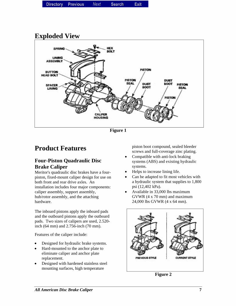
Exploded View
Figure 1
Product Features Four-Piston Quadraulic Disc Brake Caliper Meritor's quadraulic disc brakes have a four-piston, fixed-mount caliper design for use on both front and rear drive axles. An installation includes four major components: caliper assembly, support assembly, hub/rotor assembly, and the attaching hardware. The inboard pistons apply the inboard pads and the outboard pistons apply the outboard pads. Two sizes of calipers are used, 2.520-inch (64 mm) and 2.756-inch (70 mm). Features of the caliper include: • Designed for hydraulic brake systems. • Hard-mounted to the anchor plate to
eliminate caliper and anchor plate replacement.
• Designed with hardened stainless steel mounting surfaces, high temperature
piston boot compound, sealed bleeder screws and full-coverage zinc plating.
• Compatible with anti-lock braking systems (ABS) and existing hydraulic systems.
• Helps to increase lining life. • Can be adapted to fit most vehicles with
a hydraulic system that supplies to 1,800 psi (12,402 kPa).
• Available in 33,000 lbs maximum GVWR (4 x 70 mm) and maximum 24,000 lbs GVWR (4 x 64 mm).
Figure 2
All American Disc Brake Caliper 7
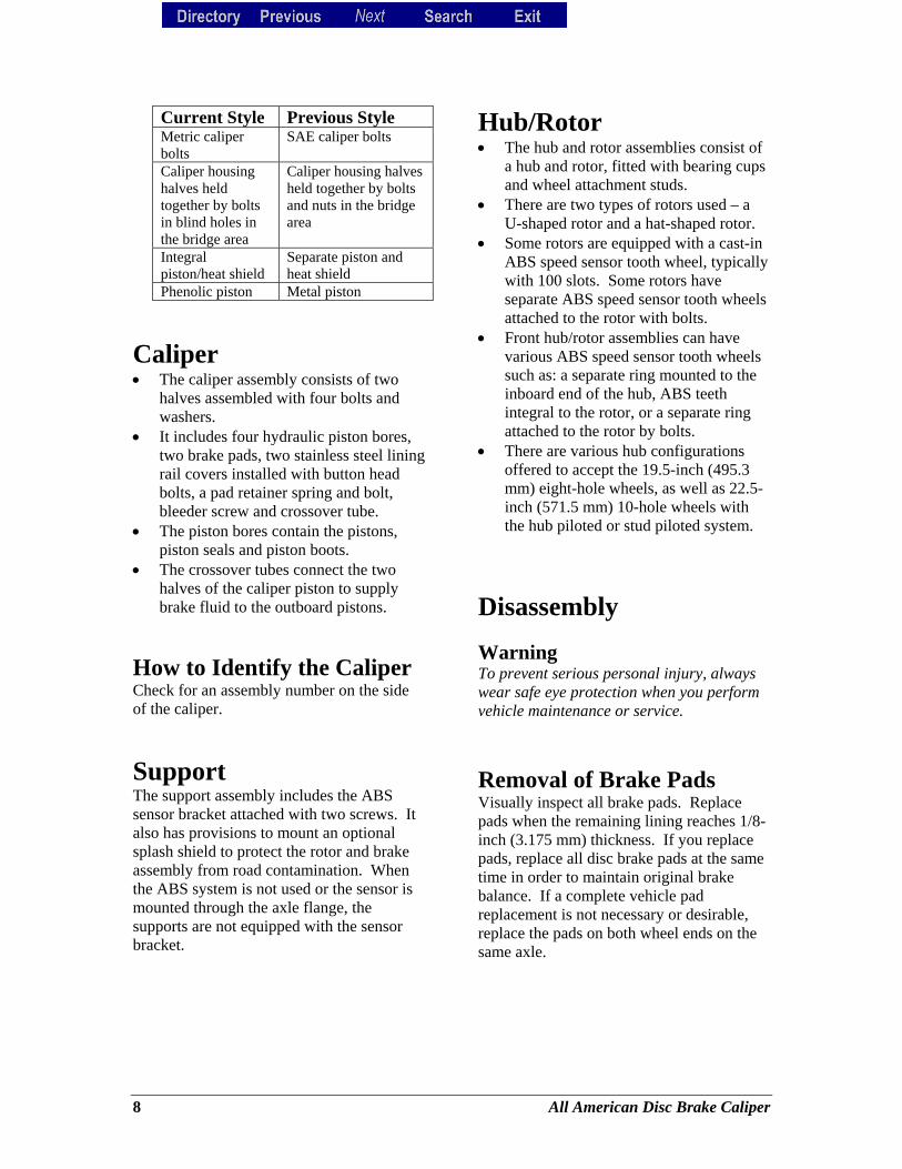
Current Style Previous Style Metric caliper bolts
SAE caliper bolts
Caliper housing halves held together by bolts in blind holes in the bridge area
Caliper housing halves held together by bolts and nuts in the bridge area
Integral piston/heat shield
Separate piston and heat shield
Phenolic piston Metal piston
Caliper • The caliper assembly consists of two
halves assembled with four bolts and washers.
• It includes four hydraulic piston bores, two brake pads, two stainless steel lining rail covers installed with button head bolts, a pad retainer spring and bolt, bleeder screw and crossover tube.
• The piston bores contain the pistons, piston seals and piston boots.
• The crossover tubes connect the two halves of the caliper piston to supply brake fluid to the outboard pistons.
How to Identify the Caliper Check for an assembly number on the side of the caliper.
Support The support assembly includes the ABS sensor bracket attached with two screws. It also has provisions to mount an optional splash shield to protect the rotor and brake assembly from road contamination. When the ABS system is not used or the sensor is mounted through the axle flange, the supports are not equipped with the sensor bracket.
Hub/Rotor • The hub and rotor assemblies consist of
a hub and rotor, fitted with bearing cups and wheel attachment studs.
• There are two types of rotors used – a U-shaped rotor and a hat-shaped rotor.
• Some rotors are equipped with a cast-in ABS speed sensor tooth wheel, typically with 100 slots. Some rotors have separate ABS speed sensor tooth wheels attached to the rotor with bolts.
• Front hub/rotor assemblies can have various ABS speed sensor tooth wheels such as: a separate ring mounted to the inboard end of the hub, ABS teeth integral to the rotor, or a separate ring attached to the rotor by bolts.
• There are various hub configurations offered to accept the 19.5-inch (495.3 mm) eight-hole wheels, as well as 22.5-inch (571.5 mm) 10-hole wheels with the hub piloted or stud piloted system.
Disassembly Warning To prevent serious personal injury, always wear safe eye protection when you perform vehicle maintenance or service.
Removal of Brake Pads Visually inspect all brake pads. Replace pads when the remaining lining reaches 1/8-inch (3.175 mm) thickness. If you replace pads, replace all disc brake pads at the same time in order to maintain original brake balance. If a complete vehicle pad replacement is not necessary or desirable, replace the pads on both wheel ends on the same axle.
8 All American Disc Brake Caliper
Replace Brake Pads 1. Raise and support the vehicle. 2. Remove the wheel and tire assembly
according to manufacturer's recommendation.
3. Remove the master cylinder reservoir filler cap. Check the brake fluid level in the reservoir. If necessary, remove fluid to keep the reservoir from overflowing when compressing pistons into the caliper.
4. Remove the pad retainer spring bolt. Figure 3.
5. Compress the caliper pistons. Figure 4.
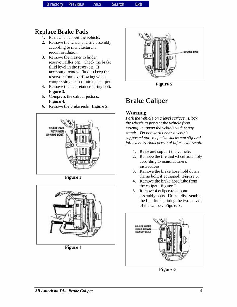
6. Remove the brake pads. Figure 5.
Figure 3
Figure 4
Figure 5
Brake Caliper Warning Park the vehicle on a level surface. Block the wheels to prevent the vehicle from moving. Support the vehicle with safety stands. Do not work under a vehicle supported only by jacks. Jacks can slip and fall over. Serious personal injury can result.
1. Raise and support the vehicle. 2. Remove the tire and wheel assembly
according to manufacturer's instructions.
3. Remove the brake hose hold down clamp bolt, if equipped. Figure 6.
4. Remove the brake hose/tube from the caliper. Figure 7.
5. Remove 4 caliper-to-support assembly bolts. Do not disassemble the four bolts joining the two halves of the caliper. Figure 8.
Figure 6
All American Disc Brake Caliper 9
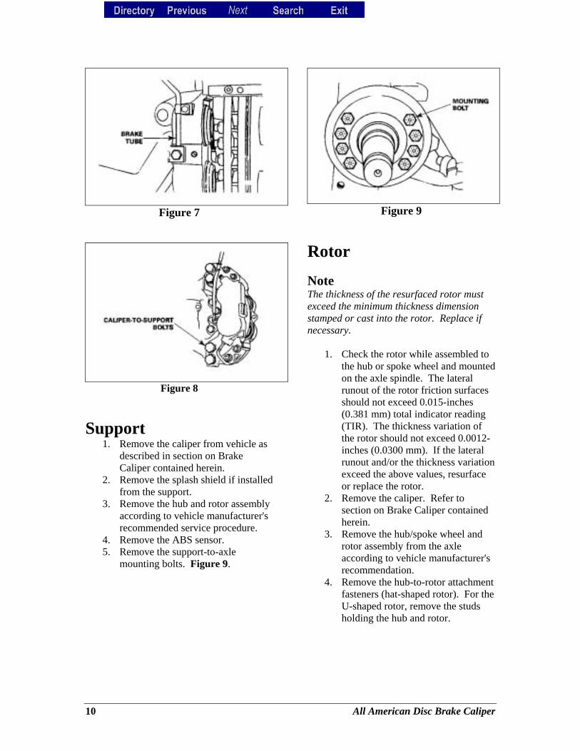
Figure 7
Figure 8
Support 1. Remove the caliper from vehicle as
described in section on Brake Caliper contained herein.
2. Remove the splash shield if installed from the support.
3. Remove the hub and rotor assembly according to vehicle manufacturer's recommended service procedure.
4. Remove the ABS sensor. 5. Remove the support-to-axle
mounting bolts. Figure 9.
Figure 9
Rotor Note The thickness of the resurfaced rotor must exceed the minimum thickness dimension stamped or cast into the rotor. Replace if necessary.
1. Check the rotor while assembled to the hub or spoke wheel and mounted on the axle spindle. The lateral runout of the rotor friction surfaces should not exceed 0.015-inches (0.381 mm) total indicator reading (TIR). The thickness variation of the rotor should not exceed 0.0012-inches (0.0300 mm). If the lateral runout and/or the thickness variation exceed the above values, resurface or replace the rotor.
2. Remove the caliper. Refer to section on Brake Caliper contained herein.
3. Remove the hub/spoke wheel and rotor assembly from the axle according to vehicle manufacturer's recommendation.
4. Remove the hub-to-rotor attachment fasteners (hat-shaped rotor). For the U-shaped rotor, remove the studs holding the hub and rotor.
10 All American Disc Brake Caliper
Disassemble and Overhaul the Brake Caliper
1. Remove the brake caliper. Refer to "Brake Caliper".
2. Drain all fluid from the caliper. 3. Push all four pistons to the bottom
of their bores. 4. Remove the piston boots by prying
the metal ring portion of the boot out of the bore with a screwdriver. Use care to avoid damage to the piston or bore. Discard the boots.
Note The C-clamp must be between the pistons on the opposite side so they may move to the wood block without striking the C-clamp. Cover pistons with shop rag to prevent brake fluid spray.
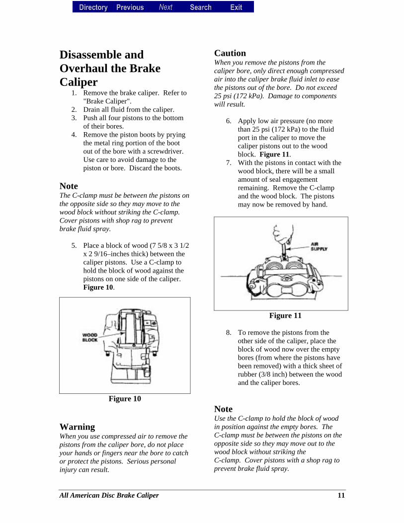
5. Place a block of wood (7 5/8 x 3 1/2 x 2 9/16–inches thick) between the caliper pistons. Use a C-clamp to hold the block of wood against the pistons on one side of the caliper. Figure 10.
Figure 10
Warning When you use compressed air to remove the pistons from the caliper bore, do not place your hands or fingers near the bore to catch or protect the pistons. Serious personal injury can result.
Caution When you remove the pistons from the caliper bore, only direct enough compressed air into the caliper brake fluid inlet to ease the pistons out of the bore. Do not exceed 25 psi (172 kPa). Damage to components will result.
6. Apply low air pressure (no more than 25 psi (172 kPa) to the fluid port in the caliper to move the caliper pistons out to the wood block. Figure 11.
7. With the pistons in contact with the wood block, there will be a small amount of seal engagement remaining. Remove the C-clamp and the wood block. The pistons may now be removed by hand.
Figure 11 8. To remove the pistons from the
other side of the caliper, place the block of wood now over the empty bores (from where the pistons have been removed) with a thick sheet of rubber (3/8 inch) between the wood and the caliper bores.
Note Use the C-clamp to hold the block of wood in position against the empty bores. The C-clamp must be between the pistons on the opposite side so they may move out to the wood block without striking the C-clamp. Cover pistons with a shop rag to prevent brake fluid spray.
All American Disc Brake Caliper 11
9. Apply low air pressure (no more than 25 psi (172 kPa)) to the fluid port in the caliper to move the caliper pistons out to the wood block.
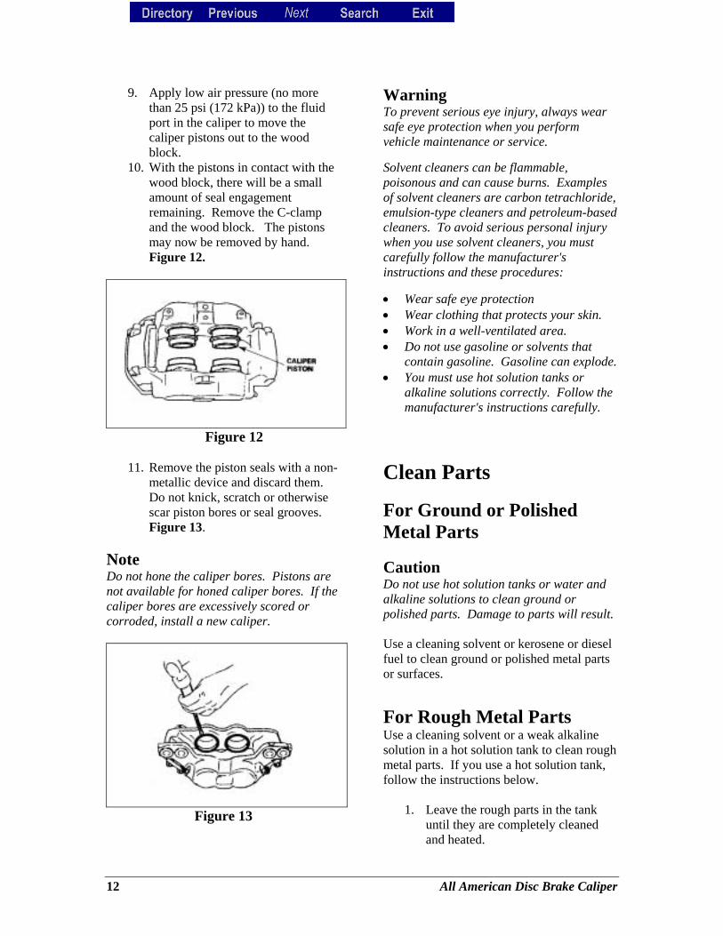
10. With the pistons in contact with the wood block, there will be a small amount of seal engagement remaining. Remove the C-clamp and the wood block. The pistons may now be removed by hand. Figure 12.
Figure 12
11. Remove the piston seals with a non-
metallic device and discard them. Do not knick, scratch or otherwise scar piston bores or seal grooves. Figure 13.
Note Do not hone the caliper bores. Pistons are not available for honed caliper bores. If the caliper bores are excessively scored or corroded, install a new caliper.
Figure 13
Warning To prevent serious eye injury, always wear safe eye protection when you perform vehicle maintenance or service. Solvent cleaners can be flammable, poisonous and can cause burns. Examples of solvent cleaners are carbon tetrachloride, emulsion-type cleaners and petroleum-based cleaners. To avoid serious personal injury when you use solvent cleaners, you must carefully follow the manufacturer's instructions and these procedures: • Wear safe eye protection • Wear clothing that protects your skin. • Work in a well-ventilated area. • Do not use gasoline or solvents that
contain gasoline. Gasoline can explode. • You must use hot solution tanks or
alkaline solutions correctly. Follow the manufacturer's instructions carefully.
Clean Parts For Ground or Polished Metal Parts Caution Do not use hot solution tanks or water and alkaline solutions to clean ground or polished parts. Damage to parts will result. Use a cleaning solvent or kerosene or diesel fuel to clean ground or polished metal parts or surfaces.
For Rough Metal Parts Use a cleaning solvent or a weak alkaline solution in a hot solution tank to clean rough metal parts. If you use a hot solution tank, follow the instructions below.
1. Leave the rough parts in the tank until they are completely cleaned and heated.
12 All American Disc Brake Caliper
2. Remove the rough parts from the tank.
3. Wash the parts with water until you remove the alkaline solution.
Dry and Inspect Parts
1. Use soft, clean paper or cloth rags or compressed air to completely dry parts immediately after you clean them.
2. Carefully inspect all parts for wear or damage before you assemble them.
3. Repair or replace worn or damaged parts.
Apply Corrosion Protection
1. Apply a thin layer of brake grease to cleaned, dried parts. Be careful that you do not apply the grease to the linings or rotor.
2. If you will store the parts, apply a special material, which prevents corrosion and rust, to all surfaces. Store parts inside special paper or other material that prevents rust and corrosion.
Warning To prevent serious eye injury, always wear safe eye protection when you perform vehicle maintenance or service.
Assembly Brake Caliper
Note When using compressed air, use air lines that are completely free of oil and moisture. All brake parts must be clean and completely dried of cleaning fluid. Use ONLY ArvinMeritor replacement parts to ensure proper caliper performance.
1. Clean caliper, caliper piston bores and fluid ports with solvent. Use compressed air to clean out and dry grooves and passages.
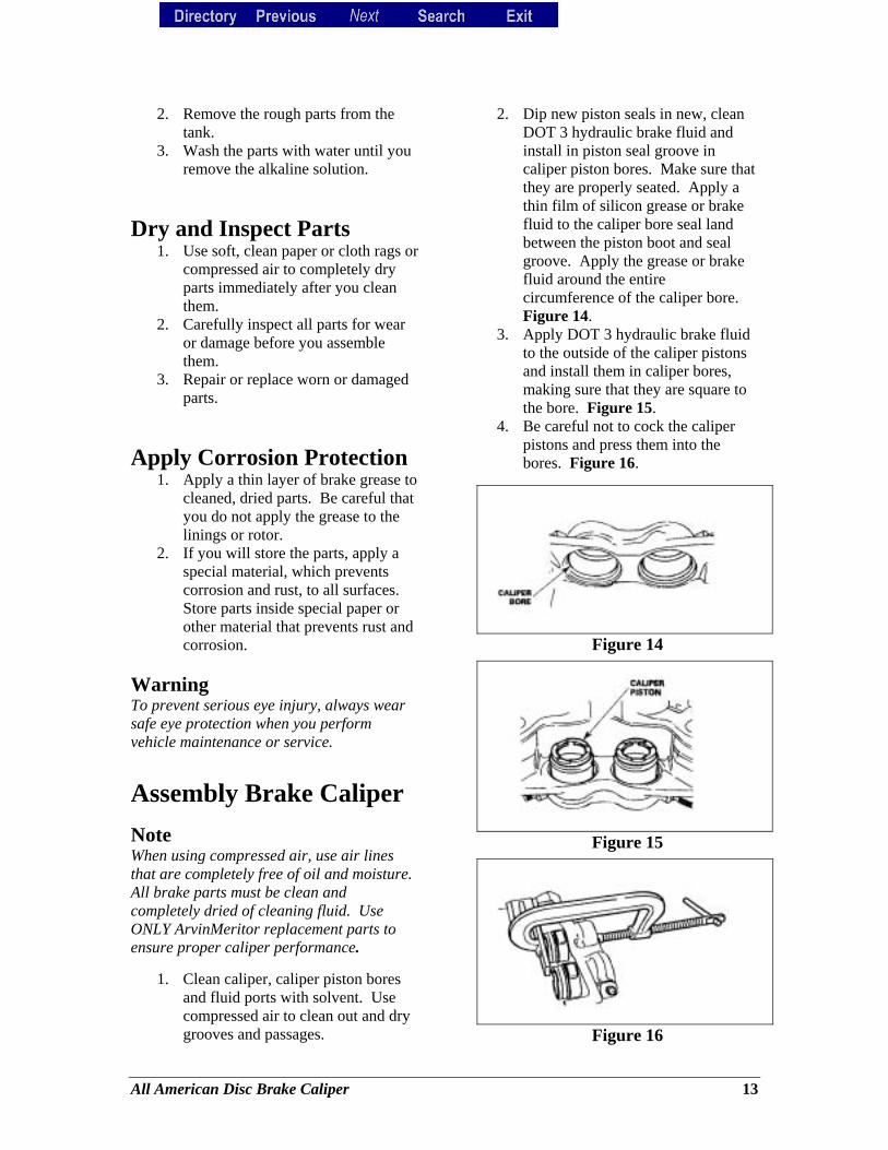
2. Dip new piston seals in new, clean DOT 3 hydraulic brake fluid and install in piston seal groove in caliper piston bores. Make sure that they are properly seated. Apply a thin film of silicon grease or brake fluid to the caliper bore seal land between the piston boot and seal groove. Apply the grease or brake fluid around the entire circumference of the caliper bore. Figure 14.
3. Apply DOT 3 hydraulic brake fluid to the outside of the caliper pistons and install them in caliper bores, making sure that they are square to the bore. Figure 15.
4. Be careful not to cock the caliper pistons and press them into the bores. Figure 16.
Figure 14
Figure 15
Figure 16
All American Disc Brake Caliper 13
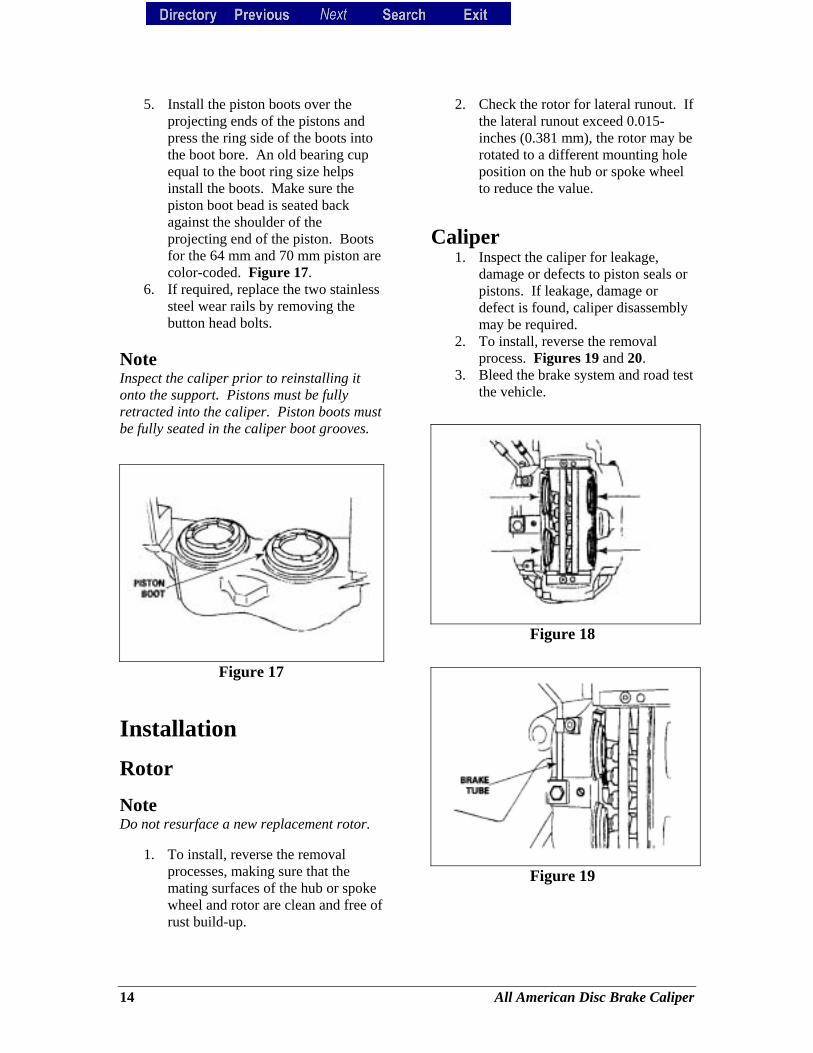
5. Install the piston boots over the projecting ends of the pistons and press the ring side of the boots into the boot bore. An old bearing cup equal to the boot ring size helps install the boots. Make sure the piston boot bead is seated back against the shoulder of the projecting end of the piston. Boots for the 64 mm and 70 mm piston are color-coded. Figure 17.
6. If required, replace the two stainless steel wear rails by removing the button head bolts.
Note Inspect the caliper prior to reinstalling it onto the support. Pistons must be fully retracted into the caliper. Piston boots must be fully seated in the caliper boot grooves.
Figure 17
Installation
Rotor
Note Do not resurface a new replacement rotor.
1. To install, reverse the removal processes, making sure that the mating surfaces of the hub or spoke wheel and rotor are clean and free of rust build-up.
2. Check the rotor for lateral runout. If the lateral runout exceed 0.015-inches (0.381 mm), the rotor may be rotated to a different mounting hole position on the hub or spoke wheel to reduce the value.
Caliper 1. Inspect the caliper for leakage,
damage or defects to piston seals or pistons. If leakage, damage or defect is found, caliper disassembly may be required.
2. To install, reverse the removal process. Figures 19 and 20.
3. Bleed the brake system and road test the vehicle.
Figure 18
Figure 19
14 All American Disc Brake Caliper
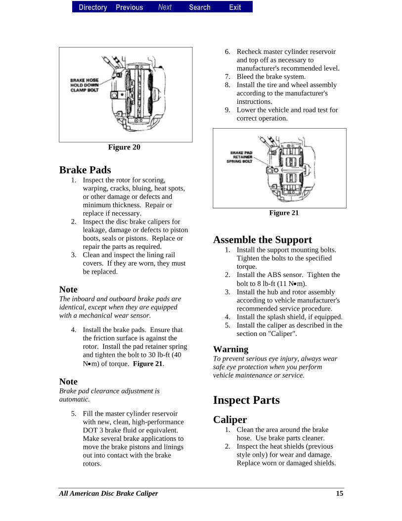
Figure 20
Brake Pads 1. Inspect the rotor for scoring,
warping, cracks, bluing, heat spots, or other damage or defects and minimum thickness. Repair or replace if necessary.
2. Inspect the disc brake calipers for leakage, damage or defects to piston boots, seals or pistons. Replace or repair the parts as required.
3. Clean and inspect the lining rail covers. If they are worn, they must be replaced.
Note The inboard and outboard brake pads are identical, except when they are equipped with a mechanical wear sensor.
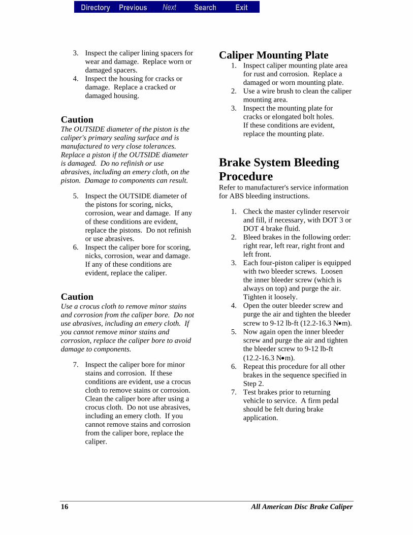
4. Install the brake pads. Ensure that the friction surface is against the rotor. Install the pad retainer spring and tighten the bolt to 30 lb-ft (40 N•m) of torque. Figure 21.
Note Brake pad clearance adjustment is automatic.
5. Fill the master cylinder reservoir with new, clean, high-performance DOT 3 brake fluid or equivalent. Make several brake applications to move the brake pistons and linings out into contact with the brake rotors.
6. Recheck master cylinder reservoir and top off as necessary to manufacturer's recommended level.
7. Bleed the brake system. 8. Install the tire and wheel assembly
according to the manufacturer's instructions.
9. Lower the vehicle and road test for correct operation.
Figure 21
Assemble the Support 1. Install the support mounting bolts.
Tighten the bolts to the specified torque.
2. Install the ABS sensor. Tighten the bolt to 8 lb-ft (11 N•m).
3. Install the hub and rotor assembly according to vehicle manufacturer's recommended service procedure.
4. Install the splash shield, if equipped. 5. Install the caliper as described in the
section on "Caliper".
Warning To prevent serious eye injury, always wear safe eye protection when you perform vehicle maintenance or service.
Inspect Parts
Caliper 1. Clean the area around the brake
hose. Use brake parts cleaner. 2. Inspect the heat shields (previous
style only) for wear and damage. Replace worn or damaged shields.
All American Disc Brake Caliper 15
3. Inspect the caliper lining spacers for wear and damage. Replace worn or damaged spacers.
4. Inspect the housing for cracks or damage. Replace a cracked or damaged housing.
Caution The OUTSIDE diameter of the piston is the caliper's primary sealing surface and is manufactured to very close tolerances. Replace a piston if the OUTSIDE diameter is damaged. Do no refinish or use abrasives, including an emery cloth, on the piston. Damage to components can result.
5. Inspect the OUTSIDE diameter of
the pistons for scoring, nicks, corrosion, wear and damage. If any of these conditions are evident, replace the pistons. Do not refinish or use abrasives.
6. Inspect the caliper bore for scoring, nicks, corrosion, wear and damage. If any of these conditions are evident, replace the caliper.
Caution Use a crocus cloth to remove minor stains and corrosion from the caliper bore. Do not use abrasives, including an emery cloth. If you cannot remove minor stains and corrosion, replace the caliper bore to avoid damage to components.
7. Inspect the caliper bore for minor stains and corrosion. If these conditions are evident, use a crocus cloth to remove stains or corrosion. Clean the caliper bore after using a crocus cloth. Do not use abrasives, including an emery cloth. If you cannot remove stains and corrosion from the caliper bore, replace the caliper.
Caliper Mounting Plate 1. Inspect caliper mounting plate area
for rust and corrosion. Replace a damaged or worn mounting plate.
2. Use a wire brush to clean the caliper mounting area.
3. Inspect the mounting plate for cracks or elongated bolt holes. If these conditions are evident, replace the mounting plate.
Brake System Bleeding Procedure Refer to manufacturer's service information for ABS bleeding instructions.
1. Check the master cylinder reservoir and fill, if necessary, with DOT 3 or DOT 4 brake fluid.
2. Bleed brakes in the following order: right rear, left rear, right front and left front.
3. Each four-piston caliper is equipped with two bleeder screws. Loosen the inner bleeder screw (which is always on top) and purge the air. Tighten it loosely.
4. Open the outer bleeder screw and purge the air and tighten the bleeder screw to 9-12 lb-ft (12.2-16.3 N•m).
5. Now again open the inner bleeder screw and purge the air and tighten the bleeder screw to 9-12 lb-ft (12.2-16.3 N•m).
6. Repeat this procedure for all other brakes in the sequence specified in Step 2.
7. Test brakes prior to returning vehicle to service. A firm pedal should be felt during brake application.
16 All American Disc Brake Caliper
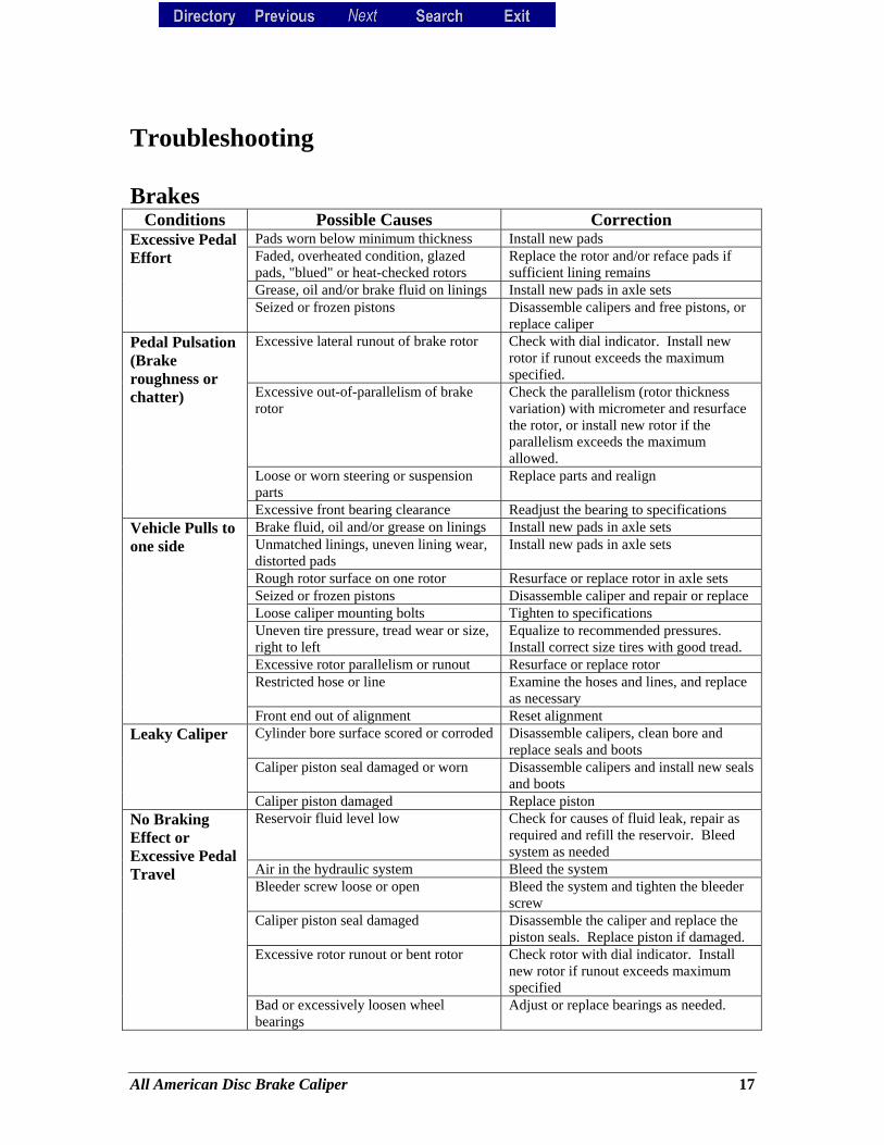
Troubleshooting Brakes
Conditions Possible Causes Correction Pads worn below minimum thickness Install new pads Faded, overheated condition, glazed pads, "blued" or heat-checked rotors
Replace the rotor and/or reface pads if sufficient lining remains
Grease, oil and/or brake fluid on linings Install new pads in axle sets
Excessive Pedal Effort
Seized or frozen pistons Disassemble calipers and free pistons, or replace caliper
Excessive lateral runout of brake rotor Check with dial indicator. Install new rotor if runout exceeds the maximum specified.
Excessive out-of-parallelism of brake rotor
Check the parallelism (rotor thickness variation) with micrometer and resurface the rotor, or install new rotor if the parallelism exceeds the maximum allowed.
Loose or worn steering or suspension parts
Replace parts and realign
Pedal Pulsation (Brake roughness or chatter)
Excessive front bearing clearance Readjust the bearing to specifications Brake fluid, oil and/or grease on linings Install new pads in axle sets Unmatched linings, uneven lining wear, distorted pads
Install new pads in axle sets
Rough rotor surface on one rotor Resurface or replace rotor in axle sets Seized or frozen pistons Disassemble caliper and repair or replace Loose caliper mounting bolts Tighten to specifications Uneven tire pressure, tread wear or size, right to left
Equalize to recommended pressures. Install correct size tires with good tread.
Excessive rotor parallelism or runout Resurface or replace rotor Restricted hose or line Examine the hoses and lines, and replace
as necessary
Vehicle Pulls to one side
Front end out of alignment Reset alignment Cylinder bore surface scored or corroded Disassemble calipers, clean bore and
replace seals and boots Caliper piston seal damaged or worn Disassemble calipers and install new seals
and boots
Leaky Caliper
Caliper piston damaged Replace piston Reservoir fluid level low Check for causes of fluid leak, repair as
required and refill the reservoir. Bleed system as needed
Air in the hydraulic system Bleed the system Bleeder screw loose or open Bleed the system and tighten the bleeder
screw Caliper piston seal damaged Disassemble the caliper and replace the
piston seals. Replace piston if damaged. Excessive rotor runout or bent rotor Check rotor with dial indicator. Install
new rotor if runout exceeds maximum specified
No Braking Effect or Excessive Pedal Travel
Bad or excessively loosen wheel bearings
Adjust or replace bearings as needed.
All American Disc Brake Caliper 17
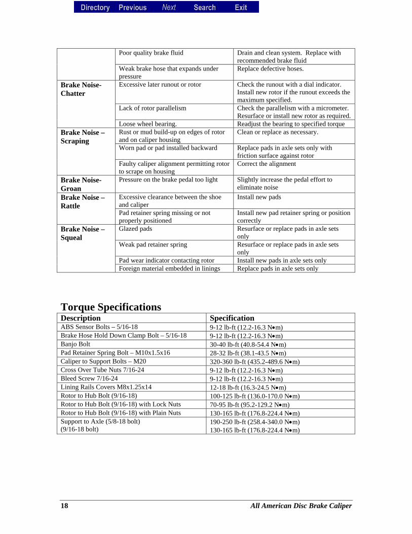
Poor quality brake fluid Drain and clean system. Replace with recommended brake fluid
Weak brake hose that expands under pressure
Replace defective hoses.
Excessive later runout or rotor Check the runout with a dial indicator. Install new rotor if the runout exceeds the maximum specified.
Lack of rotor parallelism Check the parallelism with a micrometer. Resurface or install new rotor as required.
Brake Noise-Chatter
Loose wheel bearing. Readjust the bearing to specified torque Rust or mud build-up on edges of rotor and on caliper housing
Clean or replace as necessary.
Worn pad or pad installed backward Replace pads in axle sets only with friction surface against rotor
Brake Noise – Scraping
Faulty caliper alignment permitting rotor to scrape on housing
Correct the alignment
Brake Noise-Groan
Pressure on the brake pedal too light Slightly increase the pedal effort to eliminate noise
Excessive clearance between the shoe and caliper
Install new pads Brake Noise – Rattle
Pad retainer spring missing or not properly positioned
Install new pad retainer spring or position correctly
Glazed pads Resurface or replace pads in axle sets only
Weak pad retainer spring Resurface or replace pads in axle sets only
Pad wear indicator contacting rotor Install new pads in axle sets only
Brake Noise – Squeal
Foreign material embedded in linings Replace pads in axle sets only
Torque Specifications Description Specification ABS Sensor Bolts – 5/16-18 9-12 lb-ft (12.2-16.3 N•m) Brake Hose Hold Down Clamp Bolt – 5/16-18 9-12 lb-ft (12.2-16.3 N•m) Banjo Bolt 30-40 lb-ft (40.8-54.4 N•m) Pad Retainer Spring Bolt – M10x1.5x16 28-32 lb-ft (38.1-43.5 N•m) Caliper to Support Bolts – M20 320-360 lb-ft (435.2-489.6 N•m) Cross Over Tube Nuts 7/16-24 9-12 lb-ft (12.2-16.3 N•m) Bleed Screw 7/16-24 9-12 lb-ft (12.2-16.3 N•m) Lining Rails Covers M8x1.25x14 12-18 lb-ft (16.3-24.5 N•m) Rotor to Hub Bolt (9/16-18) 100-125 lb-ft (136.0-170.0 N•m) Rotor to Hub Bolt (9/16-18) with Lock Nuts 70-95 lb-ft (95.2-129.2 N•m) Rotor to Hub Bolt (9/16-18) with Plain Nuts 130-165 lb-ft (176.8-224.4 N•m) Support to Axle (5/8-18 bolt) (9/16-18 bolt)
190-250 lb-ft (258.4-340.0 N•m) 130-165 lb-ft (176.8-224.4 N•m)
18 All American Disc Brake Caliper
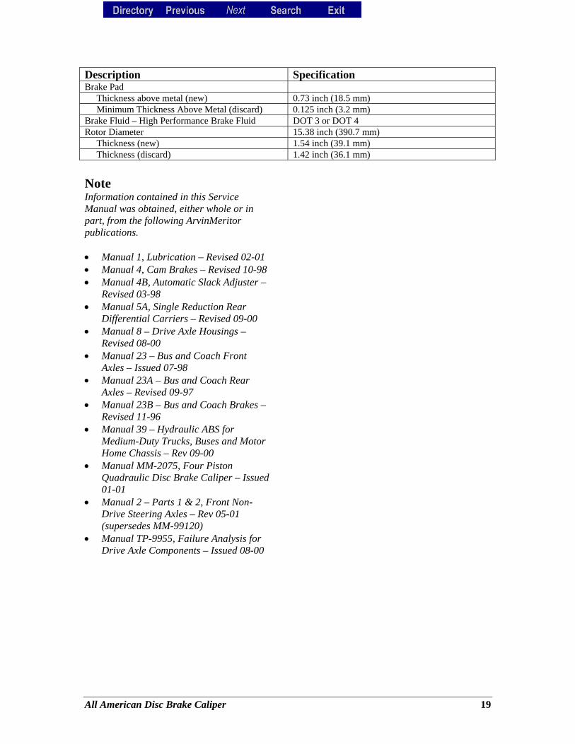
Description Specification Brake Pad Thickness above metal (new) 0.73 inch (18.5 mm) Minimum Thickness Above Metal (discard) 0.125 inch (3.2 mm) Brake Fluid – High Performance Brake Fluid DOT 3 or DOT 4 Rotor Diameter 15.38 inch (390.7 mm) Thickness (new) 1.54 inch (39.1 mm) Thickness (discard) 1.42 inch (36.1 mm) Note Information contained in this Service Manual was obtained, either whole or in part, from the following ArvinMeritor publications. • Manual 1, Lubrication – Revised 02-01 • Manual 4, Cam Brakes – Revised 10-98 • Manual 4B, Automatic Slack Adjuster –
Revised 03-98 • Manual 5A, Single Reduction Rear
Differential Carriers – Revised 09-00 • Manual 8 – Drive Axle Housings –
Revised 08-00 • Manual 23 – Bus and Coach Front
Axles – Issued 07-98 • Manual 23A – Bus and Coach Rear
Axles – Revised 09-97 • Manual 23B – Bus and Coach Brakes –
Revised 11-96 • Manual 39 – Hydraulic ABS for
Medium-Duty Trucks, Buses and Motor Home Chassis – Rev 09-00
• Manual MM-2075, Four Piston Quadraulic Disc Brake Caliper – Issued 01-01
• Manual 2 – Parts 1 & 2, Front Non-Drive Steering Axles – Rev 05-01 (supersedes MM-99120)
• Manual TP-9955, Failure Analysis for Drive Axle Components – Issued 08-00
All American Disc Brake Caliper 19
Please note that you can access current maintenance and service information in the Tech Library at arvinmeritor.com. Click Products & Services/Truck & Trailer Products/Sales and Service tab/Tech Library icon. The screen will display a list of publications by type. You can also contact ArvinMeritor's Customer Service Center at 800-535-5560 to order publications or to verify current editions. Back to Top
20 All American Disc Brake Caliper