Embed Size (px)
Citation preview
Fourth-Order Buck Converter
for Maximum Power Point
Tracking Applications
MUMMADI VEERACHARY, Senior Member, IEEE
Indian Institute of Technology Delhi
Photovoltaic arrays (PVAs) need an intermediate maximum
power point tracker as their v-i characteristics are nonlinear.
Application of switch-mode dc-dc converters are popular in
this area and the buck topology is widely used in these power
tracking applications. However, the buck converter with an
input L-C filter, with insufficient damping, will exhibit unwanted
oscillations, or it may operate at suboptimal power points for
certain solar insolations. Suitable damping must be designed
otherwise the maximum power point (MPP) becomes unstable.
Because of the variable impedance characteristic of PVA the
design of optimal damping, suitable for all solar insolations, is a
complex task. In order to eliminate these problems a fourth-order
buck converter, which will track maximum power (MP) at all
solar insolations, is proposed for the photovoltaic (PV) power
tracking applications. Mathematical models of the proposed
converter are formulated and then boundary conditions, under
which the converter capable of tracking MP, are obtained. The
combined PV power tracking scheme is simulated in PSIM and
then power tracking performance characteristics are generated.
Performance of the proposed topology is compared with the buck
converter with input filter. The proposed converter effectiveness,
in power tracking applications, is verified through experimental
studies. Micro-controller, dsPIC30F6010, is employed in the
real-time implementation of the perturb and observe (P & O)
tracking algorithm.
Manuscript received June 15, 2008; revised May 22, 2009; released
for publication November 6, 2009.
IEEE Log No. T-AES/47/2/940820.
Refereeing of this contribution was handled by S. Mazumder.
Author’s address: Dept. of Electrical Engineering, Indian Institute
of Technology Delhi, Hauz Khas, New Delhi 110016, India, E-mail:
0018-9251/11/$26.00 c° 2011 IEEE
I. INTRODUCTION
Clean and renewable energy source such as
photovoltaic (PV) power generation is expected
as one of the key technologies to mitigate global
warming. Since the PV source’s exhibit nonlinear
v-i characteristics their power output mainly depend
on the nature of the load connected to it. Hence,
direct load connection to the PV array (PVA) system
results in poor overall efficiency. As the solar panels
are still expensive their life cycle cost minimization
is essential. To achieve some of these goals, direct
connected PV systems are being replaced by PV
systems having an intermediate maximum power
point tracking (MPPT) converter. Several MPPT
algorithms with different converter combinations
[1—17] have been proposed and used to extract
maximum power (MP) from the PVA under different
operating conditions. Some of the well-established
power tracking methods are: 1) perturb and observe
algorithm (P & O), 2) incremental conductance
method (ICM), 3) voltage-based method (VBM), and
4) search-based methods (SBM). All these methods
have evolved one after another to overcome some
of the disadvantages present in other methods. Each
one of these schemes, mentioned above, has their
own advantages as well as limitations. However, the
suitability and its final selection is mainly decided
by the application and operating conditions. Hence,
the designer has to make an exercise before choosing
a particular scheme for the tracking purpose. The
main concern while choosing a tracking scheme
is the accuracy and tracking speed requirement.
Thus, a tradeoff design should be chosen so that
it results in better dynamic response as well as
the minimum steady-state oscillations in the PV
power.
The performance of a PV system depends on
several factors, of which the most important ones
are: 1) type of power converter used, 2) tracking
methodology employed, and 3) nature of filters
employed. Hence, each one of these elements is
equally responsible for the overall performance
improvement. In this direction, the designer has to
make substantial efforts while performing the PV
system design. Several studies have been conducted
and reported on the usage of intermediate power
converters for power tracking applications, which are:
conventional buck, boost, and buck-boost topologies.
In power supply application buck based derived
topologies have been reported in the literature [18]
to realize improved performance in the step-down
conversion. Exhaustive studies were also made on
the MPPT methods and their improvement. However,
in PV applications there is still a need to look into
the intermediate power converters suitability and
evolving alternative topologies in order to find a better
matching converter.
896 IEEE TRANSACTIONS ON AEROSPACE AND ELECTRONIC SYSTEMS VOL. 47, NO. 2 APRIL 2011

Several topologies have been proposed in the
literature for the PV, and most of them are dealing
quantitatively without having much mathematical
orientation. However, there are certain issues in
PV, from the converter performance point of view,
those can only be addressed and understood through
mathematical analysis. PV power tracking using
buck converters is also reported by several authors,
wherein the buck converter based power tracking
characteristics were presented and then compared
with experimental characteristics. However, there
is no discussion reported on the tracking issues,
mathematical analysis applicable to power tracking
aspects, conditions for satisfactory power tracking,
etc. From the converter performance improvement
point of view, ripple reduction through zero-ripple
filter is more popular in the dc-dc conversion [20—22],
PV power conversion, and several other power
conditioning systems. This ripple mitigation technique
has also been applied recently in energy efficient fuel
cell conversion [23—24], wherein it is demonstrated
that the zero-ripple filter significantly reduces the
input low- and high-frequency current ripples. Thus,
such solutions result in better reliability and enhanced
durability to the fuel cell power system.
The purpose of this investigation is to analyze the
buck topologies in the MPPT applications and then
evolve a modified buck topology, which will track
MP at all solar insolations leading to an improved
performance over the buck converter with input
filter (BCIF). In this direction, a fourth-order buck
converter (FOBC) is proposed for PV tracking
applications. As this converter contains the inductor
on the input side, the PVA current is smooth
and exhibits low ripple content as in comparison
with the conventional buck converter. To reduce
the ripple current even more, without using any
additional passive components, a coupled inductor
(CI) arrangement is proposed for the FOBC. This
CI arrangement not only reduces the core size but
also improves the converter performance, by way of
ripple reduction, for certain values of inductance and
coupling coefficients combination. Further, the CI in
FOBC also eliminates the problem of right half of
s-plane (RHP) zeros.
II. PHOTOVOLTAIC SYSTEM
The PV system consists of several PVA modules,
which are normally connected in series and parallel
fashion in order to realize the required voltage and
current demands, an intermediate power converter to
extract maximum available power, and a load. The
load may be of: 1) stand-alone sink type, 2) battery,
3) up-stream converters, and 4) combinations of
above. In any case to understand the whole tracking
process as well as the conditions under which a
particular converter performs its function for optimal
operation, it is necessary to model the complete
PV system. Detailed discussions of PVA modeling
aspects were already reported [12]—[16]. The PV
generator exhibits a nonlinear insolation dependent v-i
characteristic, mathematically expressed for the PVA
consisting of Ns cells in series and Np cells in parallel
as
VA =¡IARsÃNsNp
!+
μNs¤
¶ln
(1+
NpIph¡ IANpIoc
)(1)
where ¤= (q=AKT), q–electric charge;
A–Completion factor; K–Boltzmann’s constant;
T–Absolute temperature; Rs–cell series resistance;
Iph–photo current; Ioc–cell reverse saturation
current; and IA, VA are the PVA current and voltage,
respectively. As (1) gives dependence of vA¡ iA withinsolation, it is used in the simulation studies.
III. MAXIMUM POWER POINT TRACKING WITHBUCK TOPOLOGIES
Conventionally, buck converters are widely used
in PV applications, such as in: 1) front end step-down
applications, 2) battery charging, and 3) maximum
power point (MPP) tracker. However, simple
buck converter generates a lot of electromagnetic
interference (EMI) noise on account of pulsating
source current waveform. The best way to minimize
these problems is to add a low-pass filter on the
source side. Various possible filter combinations
available for dc-dc converters are: 1) connecting a
capacitor filter, 2) connecting single-stage L-C filter,
or 3) multiple-stage filters. Multiple filter stages
are recommended only when the single stage filter
is unable to meet the requirements or its design is
very large and impractical. Although the system
performance can be improved by an input filter,
they alter the converter dynamics. Numerous papers
dealing with input filter interactions on the converter
dynamics have been reported in the literature [25, 28].
Normally the input filter affects the downstream
converter stability. Appropriate care should be taken
while designing the filter stage such that its output
impedance is less than the downstream converter
input impedance jZoj< jZinj, to ensure the combinedsystem stability. Further, the components must be
designed to handle large ripple currents, and be
capable of providing sufficient damping. Insufficient
damping causes the frequency response plots to
have multiple crossover frequencies, less than
control-loop crossover frequency, leading to system
instability.
Buck converter with simple C-filter was proposed
and used in many MPPT applications. However,
this solution requires large capacitance value,
and sometimes it may not be possible to meet the
requirements as determined by the input-output
VEERACHARY: FOURTH-ORDER BUCK CONVERTER FOR MAXIMUM POWER POINT TRACKING APPLICATIONS 897
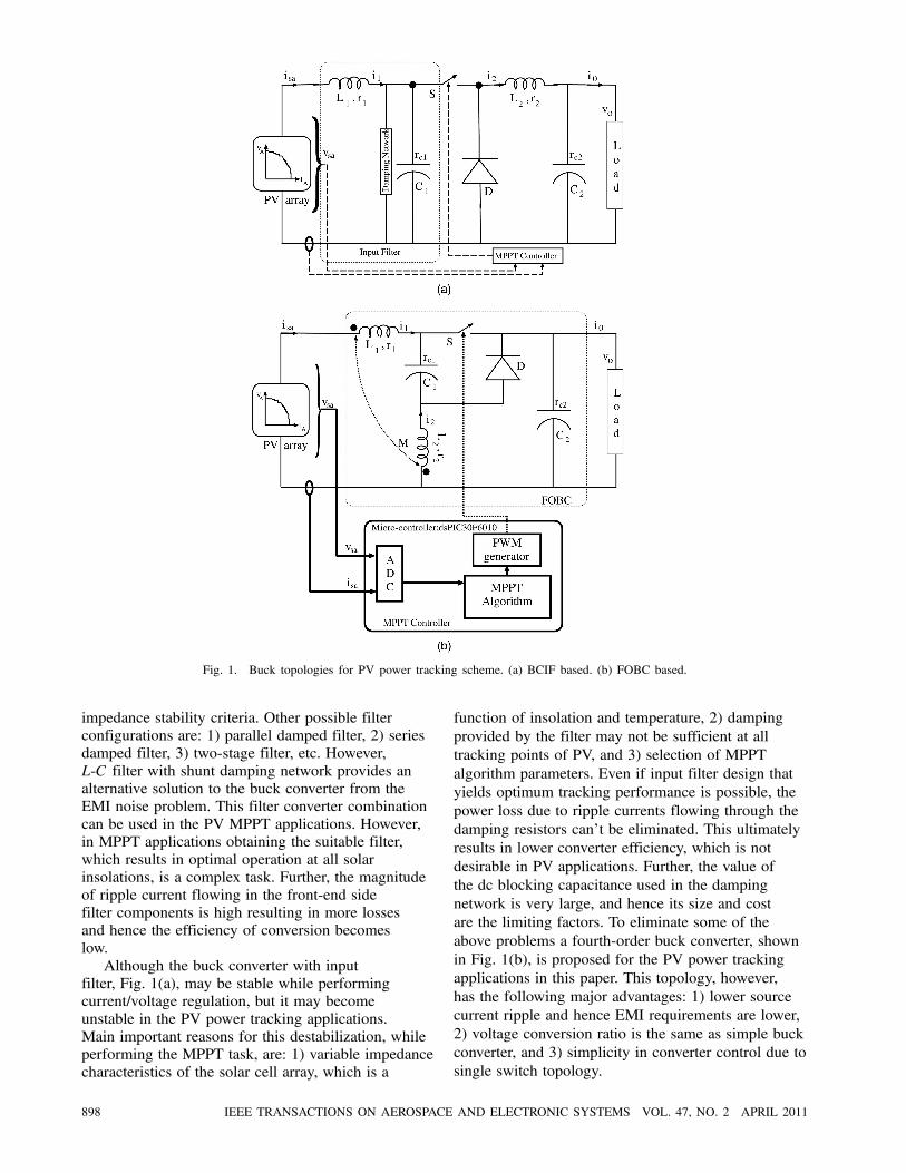
Fig. 1. Buck topologies for PV power tracking scheme. (a) BCIF based. (b) FOBC based.
impedance stability criteria. Other possible filter
configurations are: 1) parallel damped filter, 2) series
damped filter, 3) two-stage filter, etc. However,
L-C filter with shunt damping network provides an
alternative solution to the buck converter from the
EMI noise problem. This filter converter combination
can be used in the PV MPPT applications. However,
in MPPT applications obtaining the suitable filter,
which results in optimal operation at all solar
insolations, is a complex task. Further, the magnitude
of ripple current flowing in the front-end side
filter components is high resulting in more losses
and hence the efficiency of conversion becomes
low.
Although the buck converter with input
filter, Fig. 1(a), may be stable while performing
current/voltage regulation, but it may become
unstable in the PV power tracking applications.
Main important reasons for this destabilization, while
performing the MPPT task, are: 1) variable impedance
characteristics of the solar cell array, which is a
function of insolation and temperature, 2) damping
provided by the filter may not be sufficient at all
tracking points of PV, and 3) selection of MPPT
algorithm parameters. Even if input filter design that
yields optimum tracking performance is possible, the
power loss due to ripple currents flowing through the
damping resistors can’t be eliminated. This ultimately
results in lower converter efficiency, which is not
desirable in PV applications. Further, the value of
the dc blocking capacitance used in the damping
network is very large, and hence its size and cost
are the limiting factors. To eliminate some of the
above problems a fourth-order buck converter, shown
in Fig. 1(b), is proposed for the PV power tracking
applications in this paper. This topology, however,
has the following major advantages: 1) lower source
current ripple and hence EMI requirements are lower,
2) voltage conversion ratio is the same as simple buck
converter, and 3) simplicity in converter control due to
single switch topology.
898 IEEE TRANSACTIONS ON AEROSPACE AND ELECTRONIC SYSTEMS VOL. 47, NO. 2 APRIL 2011
IV. MATHEMATICAL THEORY OF FOBC FOR MPPTAPPLICATIONS
The proposed FOBC topology, shown in Fig. 1(b),
can be operated in several operating modes depending
on the load, switching frequency, and supply voltage.
However inductor current (iL1) must be continuous;
otherwise the benefits obtained from this converter
are lost. As a result the converter is analyzed here
for the continuous inductor current mode (CICM) of
operation only. Mathematical analysis of the converter
is developed in this section under the following
assumptions: 1) switching devices are ideal, 2) passive
energy storage parameters are assumed to be linear
time invariant, and 3) averaging of the converter
states has been done on the small-ripple assumption.
In CICM operation the circuit has two operating
modes: Mode-1: S-ON (0< t < dT); Mode-2: S-OFF
(dT < t < T). In each mode of operation the circuit is
linear and its behavior can easily be described by the
state-space average model [26] given by
_x= [A][x]+ [B][u], v0 = [P][x] (2)
where, [x] = [iL1 iL2 vc1 vc]t, [u] = [Vg], A=§DjAj ,
B =§DjBj , P = §DjPj , j = 1,2. The final state-space
matrices for CICM of operation are given below for
ready reference.
[A] =
0BBBBBBBBBBB@
¡ [a1L2 + aL2e]Le
¡ (aL2e¡ a2M)Le
¡ (D1M +D2L2)
Le
aL2ercLe
¡ (aL1e¡Mr1)Le
¡ (aL1e+ a2L1)Le
(D1L1 +D2M)
Le
aL1ercLe
D2C1
¡D1C1
0 0
a
rcC
a
rcC0
¡1C(R+ rc)
1CCCCCCCCCCCA[B]t =
μL2Le
¡ MLe
0 0
¶
where a1 = (D1r1 +D2r1c1), a2 = (D1r2c1 +D2r2),
L1e = (L1¡M), L2e = (L2¡M), Le = (L1L2¡M2),
r1c1 = (r1¡ rc1), r2c1 = (r2¡ rc1), a= Rrc=(R+ rc).This FOBC topology is simple and gives a voltage
transformation ratio almost identical to the buck
converter. In this process, the converter unit actually
replaces the constant load by an equivalent load that
corresponds to the effective load requirement of
the PVA at which it can deliver MP to the load. It
may not be possible, sometimes, to replace all the
values of constant loads by an equivalent value that
corresponds to the MPP load line. Achieving the
true MPPT depends on: 1) the type of switch-mode
converter used, 2) nature of load present on the
converter, 3) status of converter operation, etc. The
mathematical analysis of the proposed converter
and the desirable conditions for satisfactory MPPT
operation is discussed in the following lines. From (2)
we can easily establish the steady-state voltage gain
expression of the FOBC as
V0VA= kD (3)
where k = R=[R+D2(r1 + r2)+ r2(1¡ 2D) ¡ rc1¢D(D¡ 1)(2D¡ 1)], and VA and V0 are the averagevalues of the PVA voltage and converter load
voltage, respectively. This steady-state relationship
is derived based on the small-ripple assumption.
Under steady-state the FOBC transfers most of the
power extracted from the PV to the load, except a
small portion is going to be lost in the converter
nonidealities and in any case the power balance,
VAIA = V0I0 + losses, is ensured at all solar insolations.
The above equation together with FOBC efficiency
definition [27—28] V0I0 = ´VAIA, gives the basis for
establishing the relationship between the FOBC load
current and PVA source current as
IA =kDI0´
(4)
where I0 is the load current, and ´ is the efficiency of
the converter. From the expressions (3) and (4) the
equivalent load appearing across the PVA terminals
can be written as
VAIA= Req =
´R
k2D2(5)
and it can be controlled smoothly over wide ranges
with the help of duty ratio modulation. Here the
role of the FOBC is to force the fixed load line to
coincide with the line that intersects at the MPP
(Vm,Im) of the PVA i-v characteristic. At this MPP, the
effective equivalent impedance Req offered at the input
terminals of the converter should be equal to the load
line Rmp of the PV array, i.e.,
Rmp =´R
k2D2: (6)
VEERACHARY: FOURTH-ORDER BUCK CONVERTER FOR MAXIMUM POWER POINT TRACKING APPLICATIONS 899
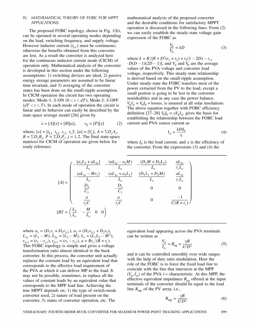
The duty ratio corresponding to MPP operation is
Dmp =
s´R
k2Rmp: (7)
In all of the above equations, the terms ´ and k are
present, which gives an indication that the power
tracker performance depends on the converter
nonidealities. Assuming ´ = 100%, k = 1, then
Dmp < 1 for the case when Rmp > R. If Rmp <
R then Dmp > 1, which will not fall within the
converter control range. Therefore, if the converter
is operating in MPPT mode then Dmp < 1, R < Rmpand the corresponding FOBC tracking zone pictorial
representation is shown in Fig. 2. For given PVA
parameters and known MPP quantities, one can
compute the expected duty ratio of the converter
from (7), and the appropriate value of the load should
satisfy R < Rmp condition.
Under ideal conditions the reflected equivalent
load appearing at the input terminals of the PVA will
be either 1 or R for the duty ratio’s zero and one,
respectively. In order to achieve satisfactory MPPT
performance, with FOBC, the connected load value
(CLV) must be less than the value of Rmp at that solar
insolation. For loads R > Rmp the converter settles
to a duty ratio, extreme limits set by the designer,
at which the power output from the array is less
than the MP. The above discussion is under ideal
conditions, i.e., duty ratio variation is (0<D < 1).
In practice the operating duty ratio is restricted to
the Dmin ·D ·Dmax range, for better utilization ofthe converter capabilities, and the corresponding load
range is
k2D2minRmp
´< R <
k2D2maxRmp
´: (8)
However, the practical D range is (0.1—0.9) and ´ is
about 90%. For these values, the approximate load
range becomes (0:011k2Rmp < R < 0:9k2Rmp). The
above discussion is valid only when the converter
is supplying a constant resistive load. However, in
most of the cases the energy extracted from the PV
sources is stored in the batteries. In that situation the
above discussion is equally valid. The explanation
for this is as follows. The basic equivalent circuit
of the battery to be charged consists of a voltage
source in series with an internal resistance and a
parallel combination of a capacitor and resistor.
Effectively this combination presents a variable
impedance/resistance across the load terminals.
However for steady-state analysis purposes, the
battery can be treated as an equivalent resistive
load and this value depends on the state-of-charge
condition of the battery. As a result the battery load
can be represented by a variable load, a function of
its voltage and current, with maximum and minimum
limits (Rbmin · Rb = f(vb, ib)· Rbmax). Here Rbmin,
Fig. 2. Load tracking region of FOBC through MPPT operation.
Rbmax corresponds to minimum charge voltage,
regulation voltage of the battery, respectively. The
variables vb, ib are battery voltage and current,
respectively. Power supplied to the battery, under the
current control case, is almost varied linearly and its
power storage variation is determined by the regulated
current value, dynamic impedance characteristic of
the battery. In case of stand-alone loads, for a given
solar insolation, the MPPT converter reaches to a
steady-state duty ratio value in short time, while for
battery loads the duty ratio variation persists until it
is fully charged. As a result, in the PV battery energy
storage systems, the MPPT should be continuously
on and one should not put a constraint such as
termination of MPPT loop to avoid the steady-state
oscillations.
V. RIPPLE CANCELLATION THROUGH COUPLEDINDUCTOR
Ripple steering/cancellation using CI is well
known in the dc-dc converters [20]. A set of two
or more inductors placed on a common magnetic
core results in a CI, and it not only requires fewer
numbers of cores, but also improves the converter
performance. Ripple reduction in the inductor current
is possible both during charging and discharging
periods. Applying the ripple reduction principles
discussed in [20] to the FOBC one can easily establish
di=dt expressions for switch-ON and switch-OFF
durations, respectively
di1dt=(L2¡M)Le
(Vg ¡V0) (9)
di1dt=(M ¡L2)V0
Le: (10)
Equations (9) and (10) represent the ripple current
flowing in the inductor L1 during switch-ON and
900 IEEE TRANSACTIONS ON AEROSPACE AND ELECTRONIC SYSTEMS VOL. 47, NO. 2 APRIL 2011
OFF states, respectively. Both equations indicate
that if L2 =M then di1=dt= 0, which means that the
inductor current (i1) is essentially a constant value or
the ripple ¢i1 ¼ 0. That means the ripple reductionis possible for the entire switching period as shown
in Fig. 9. This perfect ripple compensation theory
is valid only under ideal conditions and the exact
zero-ripple steering depends on the compensation of
the nonidealities of the system.
VI. PERFORMANCE COMPARISON OF BCIF ANDFOBC TOPOLOGIES
An FBOC and a BCIF, parameters listed in
Table III, were designed, simulated using PSIM,
built and tested. The source ripple current is slightly
higher in FOBC, while it is low in BCIF because of
L1¡C1 elements directly connected to the sourceside. In both the converters the peak current/voltage
stress on the switch and diode is identical. The FOBC
circuit structure gives an impression that the ripple
current flowing in capacitor C1 is larger in magnitude,
but actually the magnitude of current flowing in it
is identical to that flowing in the BCIF. Hence, the
I2R-losses, contributed by the series resistance of
the L1 and C1 elements, in both the converters are
almost the same. In both the topologies the ac losses
contributed by the inductor L2 series resistance is
also the same because of the identical peak-to-peak
ripple current waveforms. However, after adding the
losses occurring in the damping network of the BCIF,
its efficiency is close to the efficiency of FOBC.
In conclusion, both BCIF and FOBC circuits show
almost identical performance, from the steady-state
point of view, and their efficiencies are also of the
same order.
Development of the small-signal model (SSM) for
the converters FOBC and BCIF [18, 25], is essential
in order to study their dynamical properties in the
power tracking process. The PV supplied converters
SSM consists of a linearized model of the converter
and on the input side the PVA is being replaced by
the incremental impedance jZsj= Rmpp. Due to paperlength restrictions the full SSM development is not
discussed here and the readers can easily obtain these
models employing the methodology presented in the
references. To have a fair comparison, small-signal
transfer functions (TFs) of the BCIF and FOBC are
derived using the signal flow graph small-signal
linearization method and are tabulated in Tables I and
II, respectively. The converters important small-signal
TF frequency response characteristics (the figures
were not given here due to space limitation) were
plotted, and these observations reveal that almost
all the TFs listed in Table I and II, show similar
variation except for v0=d, i1(s)=d(s) TFs and their
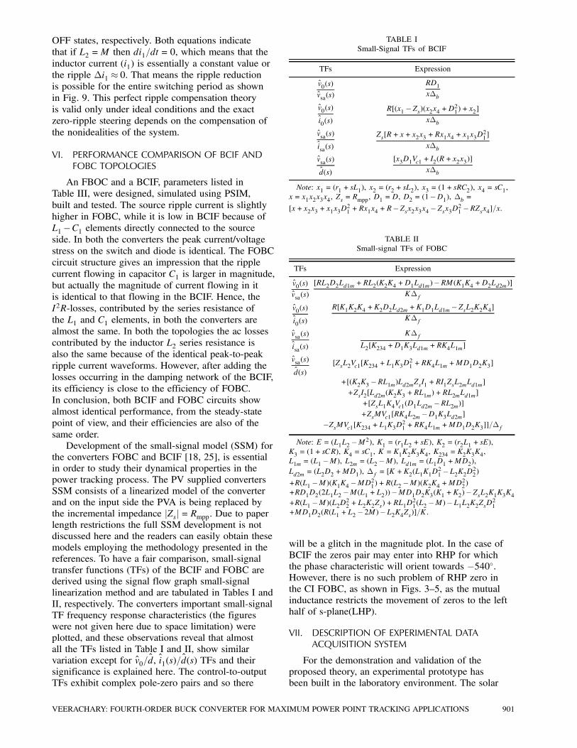
significance is explained here. The control-to-output
TFs exhibit complex pole-zero pairs and so there
TABLE I
Small-Signal TFs of BCIF
TFs Expression
v0(s)
vsa(s)
RD1x¢b
v0(s)
i0(s)
R[(x1¡Zs)(x2x4 +D21)+ x2]x¢b
vsa(s)
isa(s)
Zs[R+ x+ x2x3 +Rx1x4 + x1x3D21]
x¢b
vsa(s)
d(s)
[x3D1Vc1 + I2(R+ x2x3)]
x¢b
Note: x1 = (r1 + sL1), x2 = (r2 + sL2), x3 = (1+ sRC2), x4 = sC1,
x= x1x2x3x4, Zs = Rmpp, D1 =D, D2 = (1¡D1), ¢b =[x+ x2x3 + x1x3D
21+Rx1x4 +R¡Zsx2x3x4¡Zsx3D21 ¡RZsx4]=x.
TABLE II
Small-signal TFs of FOBC
TFs Expression
v0(s)
vsa(s)
[RL2D2Ld1m+RL2(K2K4 +D1Ld1m)¡RM(K1K4 +D2Ld2m)]K¢f
v0(s)
i0(s)
R[K1K2K4 +K2D2Ld2m +K1D1Ld1m¡ZsL2K2K4]K¢f
vsa(s)
isa(s)
K¢f
L2[K234 +D1K3Ld1m +RK4L1m]
vsa(s)
d(s)
[ZsL2Vc1[K234 +L1K3D21+RK4L1m +MD1D2K3]
+[(K2K3 ¡RL1m)Ld2mZsI1 +RI1ZsL2mLd1m]+ZsI2[Ld2m(K2K3 +RL1m) +RL2mLd1m]
+[ZsL1K4Vc1(D1Ld2m ¡RL2m)]+ZsMVc1[RK4L2m ¡D1K3Ld2m]
¡ZsMVc1[K234 +L1K3D21 +RK4L1m +MD1D2K3]]=¢fNote: E = (L1L2 ¡M2), K1 = (r1L2 + sE), K2 = (r2L1 + sE),
K3 = (1+ sCR), K4 = sC1, K = K1K2K3K4, K234 = K2K3K4,
L1m = (L1 ¡M), L2m = (L2¡M), Ld1m = (L1D1 +MD2),Ld2m = (L2D2 +MD1), ¢f = [K +K2(L1K1D
21¡L2K2D22)
+R(L1 ¡M)(K1K4 ¡MD21)+R(L2 ¡M)(K2K4 +MD22)+RD1D2(2L1L2 ¡M(L1 +L2))¡MD1D2K3(K1 +K2)¡ZsL2K1K3K4+R(L1 ¡M)(L2D22 +L2K2Zs) +RL1D21(L2¡M)¡L1L2K2ZsD21+MD1D2(R(L1 +L2 ¡ 2M)¡L2K4Zs)]=K.
will be a glitch in the magnitude plot. In the case of
BCIF the zeros pair may enter into RHP for which
the phase characteristic will orient towards ¡540±.However, there is no such problem of RHP zero in
the CI FOBC, as shown in Figs. 3—5, as the mutual
inductance restricts the movement of zeros to the left
half of s-plane(LHP).
VII. DESCRIPTION OF EXPERIMENTAL DATAACQUISITION SYSTEM
For the demonstration and validation of the
proposed theory, an experimental prototype has
been built in the laboratory environment. The solar
VEERACHARY: FOURTH-ORDER BUCK CONVERTER FOR MAXIMUM POWER POINT TRACKING APPLICATIONS 901
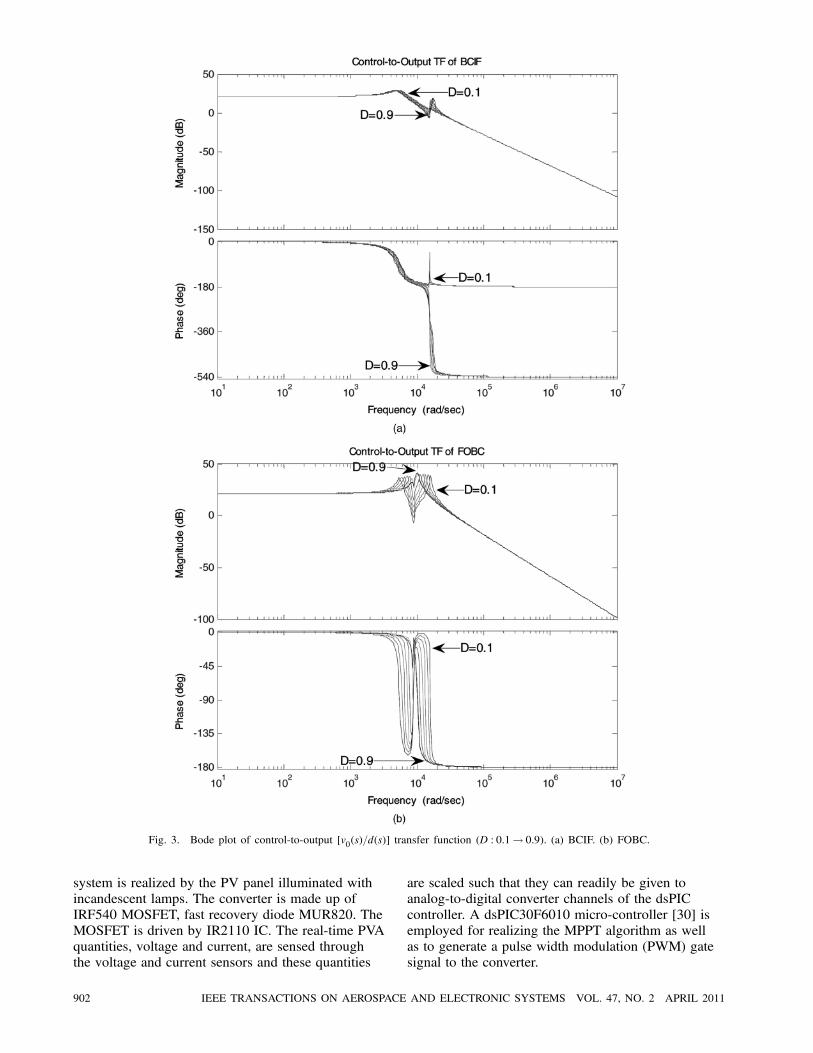
Fig. 3. Bode plot of control-to-output [v0(s)=d(s)] transfer function (D : 0:1! 0:9). (a) BCIF. (b) FOBC.
system is realized by the PV panel illuminated with
incandescent lamps. The converter is made up of
IRF540 MOSFET, fast recovery diode MUR820. The
MOSFET is driven by IR2110 IC. The real-time PVA
quantities, voltage and current, are sensed through
the voltage and current sensors and these quantities
are scaled such that they can readily be given to
analog-to-digital converter channels of the dsPIC
controller. A dsPIC30F6010 micro-controller [30] is
employed for realizing the MPPT algorithm as well
as to generate a pulse width modulation (PWM) gate
signal to the converter.
902 IEEE TRANSACTIONS ON AEROSPACE AND ELECTRONIC SYSTEMS VOL. 47, NO. 2 APRIL 2011
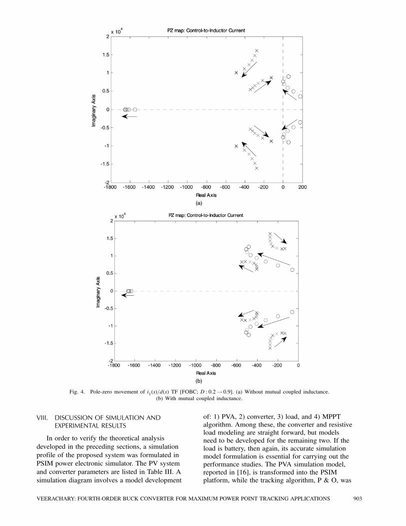
Fig. 4. Pole-zero movement of i1(s)=d(s) TF [FOBC; D : 0:2! 0:9]. (a) Without mutual coupled inductance.
(b) With mutual coupled inductance.
VIII. DISCUSSION OF SIMULATION ANDEXPERIMENTAL RESULTS
In order to verify the theoretical analysis
developed in the preceding sections, a simulation
profile of the proposed system was formulated in
PSIM power electronic simulator. The PV system
and converter parameters are listed in Table III. A
simulation diagram involves a model development
of: 1) PVA, 2) converter, 3) load, and 4) MPPT
algorithm. Among these, the converter and resistive
load modeling are straight forward, but models
need to be developed for the remaining two. If the
load is battery, then again, its accurate simulation
model formulation is essential for carrying out the
performance studies. The PVA simulation model,
reported in [16], is transformed into the PSIM
platform, while the tracking algorithm, P & O, was
VEERACHARY: FOURTH-ORDER BUCK CONVERTER FOR MAXIMUM POWER POINT TRACKING APPLICATIONS 903
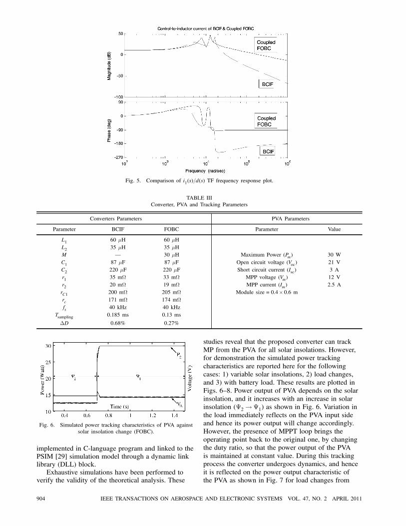
Fig. 5. Comparison of i1(s)=d(s) TF frequency response plot.
TABLE III
Converter, PVA and Tracking Parameters
Converters Parameters PVA Parameters
Parameter BCIF FOBC Parameter Value
L1 60 ¹H 60 ¹H
L2 35 ¹H 35 ¹H
M – 30 ¹H Maximum Power (Pm) 30 W
C1 87 ¹F 87 ¹F Open circuit voltage (Voc) 21 V
C2 220 ¹F 220 ¹F Short circuit current (Isc) 3 A
r1 35 m− 33 m− MPP voltage (Vm) 12 V
r2 20 m− 19 m− MPP current (Im) 2.5 A
rC1 200 m− 205 m− Module size = 0:4£ 0:6 mrc 171 m− 174 m−
fs 40 kHz 40 kHz
Tsampling 0.185 ms 0.13 ms
¢D 0.68% 0.27%
Fig. 6. Simulated power tracking characteristics of PVA against
solar insolation change (FOBC).
implemented in C-language program and linked to the
PSIM [29] simulation model through a dynamic link
library (DLL) block.
Exhaustive simulations have been performed to
verify the validity of the theoretical analysis. These
studies reveal that the proposed converter can track
MP from the PVA for all solar insolations. However,
for demonstration the simulated power tracking
characteristics are reported here for the following
cases: 1) variable solar insolations, 2) load changes,
and 3) with battery load. These results are plotted in
Figs. 6—8. Power output of PVA depends on the solar
insolation, and it increases with an increase in solar
insolation (ª2!ª1) as shown in Fig. 6. Variation in
the load immediately reflects on the PVA input side
and hence its power output will change accordingly.
However, the presence of MPPT loop brings the
operating point back to the original one, by changing
the duty ratio, so that the power output of the PVA
is maintained at constant value. During this tracking
process the converter undergoes dynamics, and hence
it is reflected on the power output characteristic of
the PVA as shown in Fig. 7 for load changes from
904 IEEE TRANSACTIONS ON AEROSPACE AND ELECTRONIC SYSTEMS VOL. 47, NO. 2 APRIL 2011
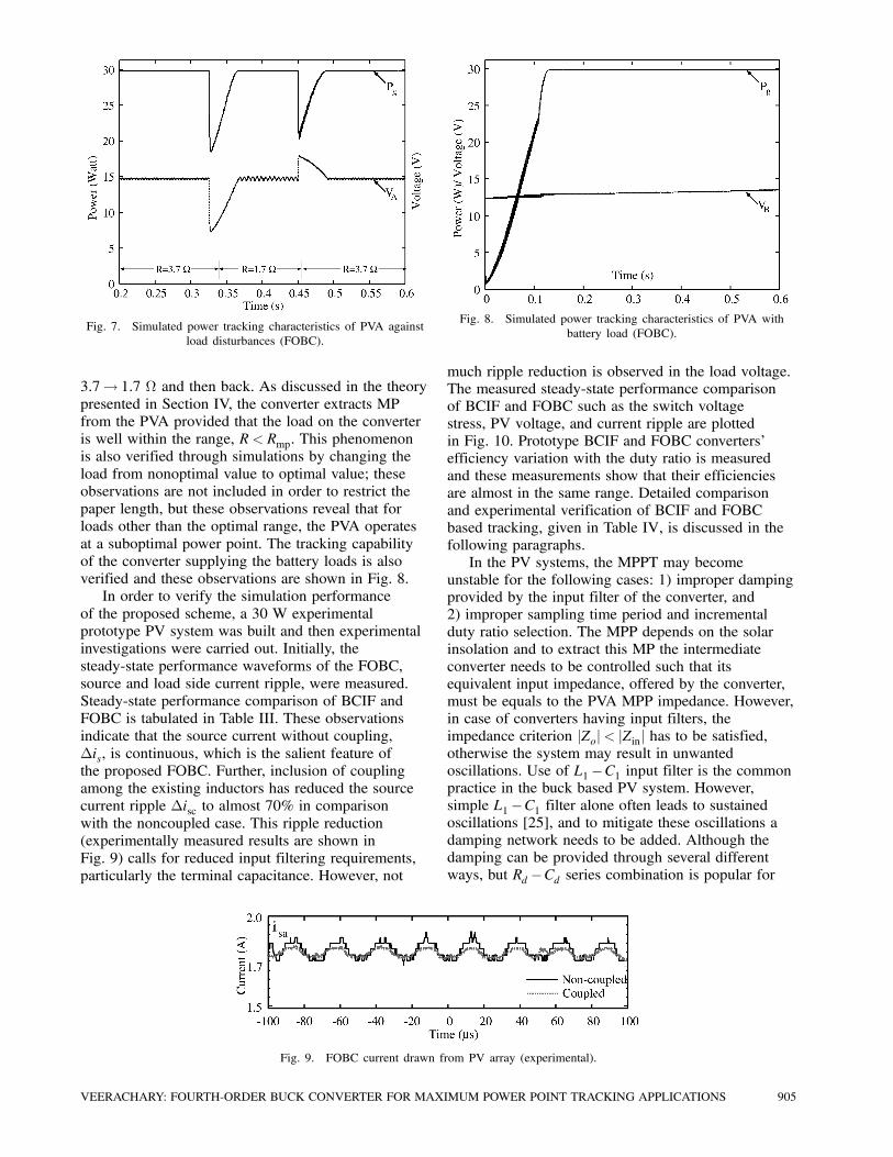
Fig. 7. Simulated power tracking characteristics of PVA against
load disturbances (FOBC).
3:7! 1:7 − and then back. As discussed in the theory
presented in Section IV, the converter extracts MP
from the PVA provided that the load on the converter
is well within the range, R < Rmp. This phenomenon
is also verified through simulations by changing the
load from nonoptimal value to optimal value; these
observations are not included in order to restrict the
paper length, but these observations reveal that for
loads other than the optimal range, the PVA operates
at a suboptimal power point. The tracking capability
of the converter supplying the battery loads is also
verified and these observations are shown in Fig. 8.
In order to verify the simulation performance
of the proposed scheme, a 30 W experimental
prototype PV system was built and then experimental
investigations were carried out. Initially, the
steady-state performance waveforms of the FOBC,
source and load side current ripple, were measured.
Steady-state performance comparison of BCIF and
FOBC is tabulated in Table III. These observations
indicate that the source current without coupling,
¢is, is continuous, which is the salient feature of
the proposed FOBC. Further, inclusion of coupling
among the existing inductors has reduced the source
current ripple ¢isc to almost 70% in comparison
with the noncoupled case. This ripple reduction
(experimentally measured results are shown in
Fig. 9) calls for reduced input filtering requirements,
particularly the terminal capacitance. However, not
Fig. 9. FOBC current drawn from PV array (experimental).
Fig. 8. Simulated power tracking characteristics of PVA with
battery load (FOBC).
much ripple reduction is observed in the load voltage.The measured steady-state performance comparison
of BCIF and FOBC such as the switch voltage
stress, PV voltage, and current ripple are plotted
in Fig. 10. Prototype BCIF and FOBC converters’
efficiency variation with the duty ratio is measured
and these measurements show that their efficiencies
are almost in the same range. Detailed comparison
and experimental verification of BCIF and FOBC
based tracking, given in Table IV, is discussed in the
following paragraphs.
In the PV systems, the MPPT may become
unstable for the following cases: 1) improper dampingprovided by the input filter of the converter, and
2) improper sampling time period and incremental
duty ratio selection. The MPP depends on the solar
insolation and to extract this MP the intermediate
converter needs to be controlled such that its
equivalent input impedance, offered by the converter,
must be equals to the PVA MPP impedance. However,
in case of converters having input filters, the
impedance criterion jZoj< jZinj has to be satisfied,otherwise the system may result in unwanted
oscillations. Use of L1¡C1 input filter is the commonpractice in the buck based PV system. However,
simple L1¡C1 filter alone often leads to sustainedoscillations [25], and to mitigate these oscillations a
damping network needs to be added. Although the
damping can be provided through several different
ways, but Rd ¡Cd series combination is popular for
VEERACHARY: FOURTH-ORDER BUCK CONVERTER FOR MAXIMUM POWER POINT TRACKING APPLICATIONS 905
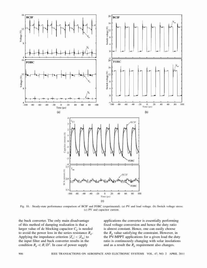
Fig. 10. Steady-state performance comparison of BCIF and FOBC (experimental). (a) PV and load voltage. (b) Switch voltage stress.
(c) PV and capacitor current.
the buck converter. The only main disadvantage
of this method of damping realization is that a
larger value of dc blocking capacitor Cd is needed
to avoid the power loss in the series resistance Rd.
Applying the impedance criterion jZoj< jZinj tothe input filter and buck converter results in the
condition Rd¿ R=D2. In case of power supply
applications the converter is essentially performing
fixed voltage conversion and hence the duty ratio
is almost constant. Hence, one can easily choose
the Rd value satisfying the constraint. However, in
the PV-MPPT applications for a given load the duty
ratio is continuously changing with solar insolations
and as a result the Rd requirement also changes.
906 IEEE TRANSACTIONS ON AEROSPACE AND ELECTRONIC SYSTEMS VOL. 47, NO. 2 APRIL 2011
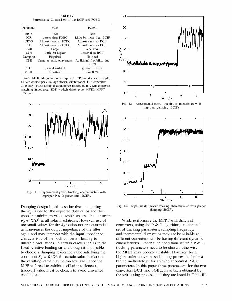
TABLE IV
Performance Comparison of the BCIF and FOBC
Parameter BCIF FOBC
MCR Two One
ICR Lesser than FOBC Little bit more than BCIF
DPVS Almost same as FOBC Almost same as BCIF
CE Almost same as FOBC Almost same as BCIF
TCR Large Very small
Cost Little bit higher Lower than BCIF
Damping Required No-need
CMI Same as basic converters Additional flexibility due
to CI
SDT ground isolated ground isolated
MPTE 91—96% 95—98.5%
Note: MCR: Magnetic cores required, ICR: input current ripple,
DPVS: device peak voltage stress(switch/diode), CE: converter
efficiency, TCR: terminal capacitance requirement, CMI: converter
matching impedance, SDT: wwitch driver type, MPTE: MPPT
efficiency.
Fig. 11. Experimental power tracking characteristics with
improper P & O parameters (BCIF).
Damping design in this case involves computing
the Rd values for the expected duty ratios and then
choosing minimum value, which ensures the constraint
Rd¿ R=D2 at all solar insolations. However, use of
too small values for the Rd is also not recommended
as it increases the output impedance of the filter
again and may intersect with the input impedance
characteristic of the buck converter, leading to
unstable oscillations. In certain cases, such as in the
fixed resistive loading case, although it is possible
to choose a damping resistance value satisfying the
constraint Rd¿ R=D2, for certain solar insolations
the resulting value may be too low and hence the
MPP is forced to exhibit oscillations. Hence a
trade-off value must be chosen to avoid unwanted
oscillations.
Fig. 12. Experimental power tracking characteristics with
improper damping (BCIF).
Fig. 13. Experimental power tracking characteristics with proper
damping (BCIF).
While performing the MPPT with different
converters, using the P & O algorithm, an identical
set of tracking parameters, sampling frequency,
and incremental duty ratios may not be suitable as
different converters will be having different dynamic
characteristics. Under such conditions suitable P & O
tracking parameters need to be chosen, otherwise
the MPPT may become unstable. However, for a
higher order converter self-tuning process is the best
tuning methodology for arriving at optimal P & O
parameters. In this paper these parameters, for the two
converters BCIF and FOBC, have been obtained by
the self-tuning process, and they are listed in Table III.
VEERACHARY: FOURTH-ORDER BUCK CONVERTER FOR MAXIMUM POWER POINT TRACKING APPLICATIONS 907
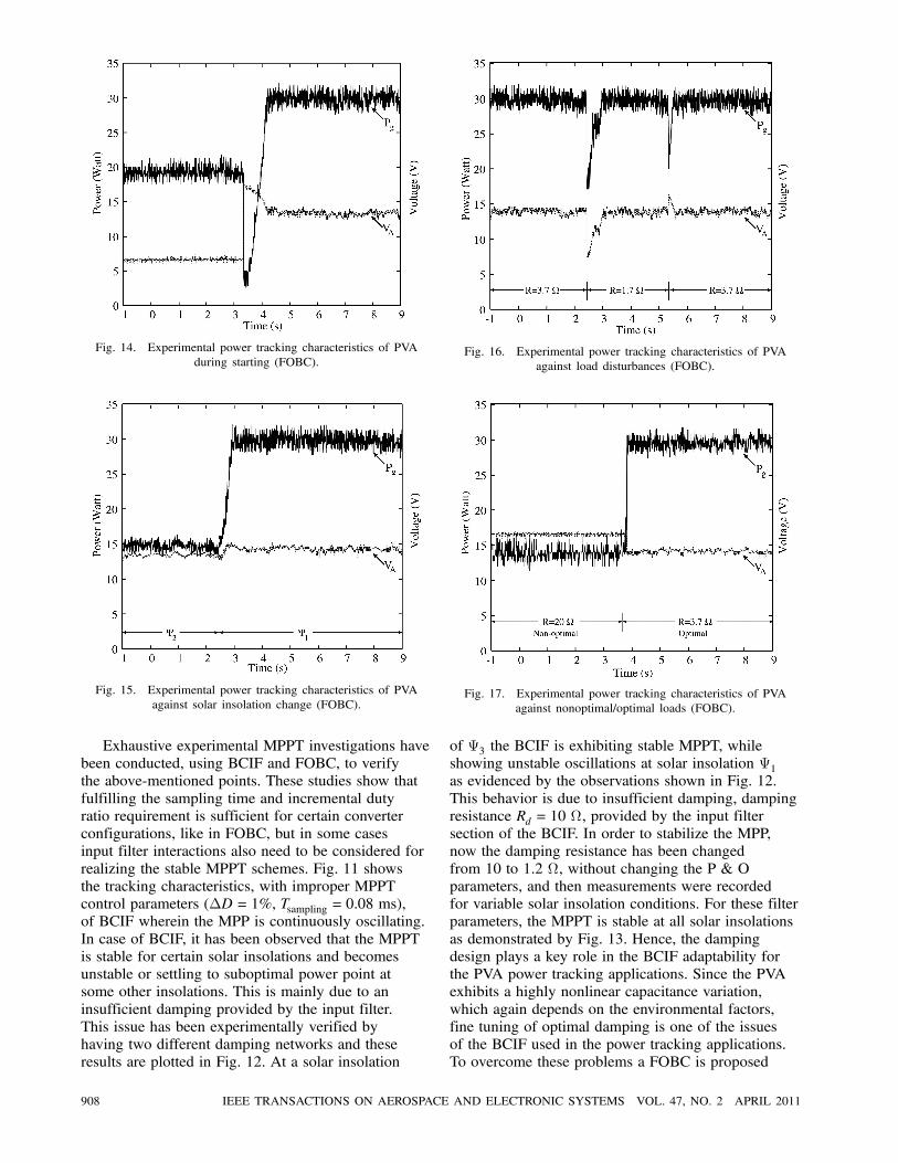
Fig. 14. Experimental power tracking characteristics of PVA
during starting (FOBC).
Fig. 15. Experimental power tracking characteristics of PVA
against solar insolation change (FOBC).
Exhaustive experimental MPPT investigations have
been conducted, using BCIF and FOBC, to verify
the above-mentioned points. These studies show that
fulfilling the sampling time and incremental duty
ratio requirement is sufficient for certain converter
configurations, like in FOBC, but in some cases
input filter interactions also need to be considered for
realizing the stable MPPT schemes. Fig. 11 shows
the tracking characteristics, with improper MPPT
control parameters (¢D = 1%, Tsampling = 0:08 ms),
of BCIF wherein the MPP is continuously oscillating.
In case of BCIF, it has been observed that the MPPT
is stable for certain solar insolations and becomes
unstable or settling to suboptimal power point at
some other insolations. This is mainly due to an
insufficient damping provided by the input filter.
This issue has been experimentally verified by
having two different damping networks and these
results are plotted in Fig. 12. At a solar insolation
Fig. 16. Experimental power tracking characteristics of PVA
against load disturbances (FOBC).
Fig. 17. Experimental power tracking characteristics of PVA
against nonoptimal/optimal loads (FOBC).
of ª3 the BCIF is exhibiting stable MPPT, while
showing unstable oscillations at solar insolation ª1as evidenced by the observations shown in Fig. 12.
This behavior is due to insufficient damping, damping
resistance Rd = 10 −, provided by the input filter
section of the BCIF. In order to stabilize the MPP,
now the damping resistance has been changed
from 10 to 1.2 −, without changing the P & O
parameters, and then measurements were recorded
for variable solar insolation conditions. For these filter
parameters, the MPPT is stable at all solar insolations
as demonstrated by Fig. 13. Hence, the damping
design plays a key role in the BCIF adaptability for
the PVA power tracking applications. Since the PVA
exhibits a highly nonlinear capacitance variation,
which again depends on the environmental factors,
fine tuning of optimal damping is one of the issues
of the BCIF used in the power tracking applications.
To overcome these problems a FOBC is proposed
908 IEEE TRANSACTIONS ON AEROSPACE AND ELECTRONIC SYSTEMS VOL. 47, NO. 2 APRIL 2011
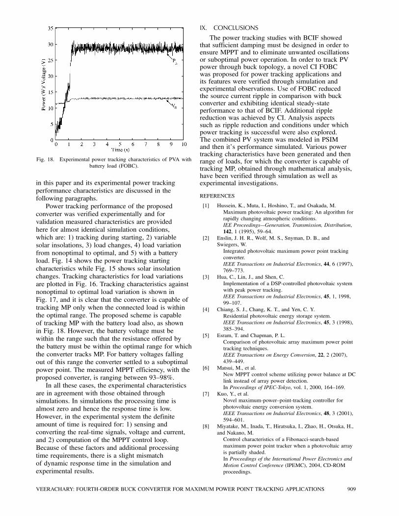
Fig. 18. Experimental power tracking characteristics of PVA with
battery load (FOBC).
in this paper and its experimental power tracking
performance characteristics are discussed in the
following paragraphs.
Power tracking performance of the proposed
converter was verified experimentally and for
validation measured characteristics are provided
here for almost identical simulation conditions,
which are: 1) tracking during starting, 2) variable
solar insolations, 3) load changes, 4) load variation
from nonoptimal to optimal, and 5) with a battery
load. Fig. 14 shows the power tracking starting
characteristics while Fig. 15 shows solar insolation
changes. Tracking characteristics for load variations
are plotted in Fig. 16. Tracking characteristics against
nonoptimal to optimal load variation is shown in
Fig. 17, and it is clear that the converter is capable of
tracking MP only when the connected load is within
the optimal range. The proposed scheme is capable
of tracking MP with the battery load also, as shown
in Fig. 18. However, the battery voltage must be
within the range such that the resistance offered by
the battery must be within the optimal range for which
the converter tracks MP. For battery voltages falling
out of this range the converter settled to a suboptimal
power point. The measured MPPT efficiency, with the
proposed converter, is ranging between 93—98%.
In all these cases, the experimental characteristics
are in agreement with those obtained through
simulations. In simulations the processing time is
almost zero and hence the response time is low.
However, in the experimental system the definite
amount of time is required for: 1) sensing and
converting the real-time signals, voltage and current,
and 2) computation of the MPPT control loop.
Because of these factors and additional processing
time requirements, there is a slight mismatch
of dynamic response time in the simulation and
experimental results.
IX. CONCLUSIONS
The power tracking studies with BCIF showedthat sufficient damping must be designed in order toensure MPPT and to eliminate unwanted oscillationsor suboptimal power operation. In order to track PVpower through buck topology, a novel CI FOBCwas proposed for power tracking applications andits features were verified through simulation andexperimental observations. Use of FOBC reducedthe source current ripple in comparison with buckconverter and exhibiting identical steady-stateperformance to that of BCIF. Additional ripplereduction was achieved by CI. Analysis aspectssuch as ripple reduction and conditions under whichpower tracking is successful were also explored.The combined PV system was modeled in PSIMand then it’s performance simulated. Various powertracking characteristics have been generated and thenrange of loads, for which the converter is capable oftracking MP, obtained through mathematical analysis,have been verified through simulation as well asexperimental investigations.
REFERENCES
[1] Hussein, K., Muta, I., Hoshino, T., and Osakada, M.
Maximum photovoltaic power tracking: An algorithm for
rapidly changing atmospheric conditions.
IEE Proceedings–Generation, Transmission, Distribution,
142, 1 (1995), 59—64.
[2] Enslin, J. H. R., Wolf, M. S., Snyman, D. B., and
Swiegers, W.
Integrated photovoltaic maximum power point tracking
converter.
IEEE Transactions on Industrial Electronics, 44, 6 (1997),
769—773.
[3] Hua, C., Lin, J., and Shen, C.
Implementation of a DSP-controlled photovoltaic system
with peak power tracking.
IEEE Transactions on Industrial Electronics, 45, 1, 1998,
99—107.
[4] Chiang, S. J., Chang, K. T., and Yen, C. Y.
Residential photovoltaic energy storage system.
IEEE Transactions on Industrial Electronics, 45, 3 (1998),
385—394.
[5] Esram, T. and Chapman, P. L.
Comparison of photovoltaic array maximum power point
tracking techniques.
IEEE Transactions on Energy Conversion, 22, 2 (2007),
439—449.
[6] Matsui, M., et al.
New MPPT control scheme utilizing power balance at DC
link instead of array power detection.
In Proceedings of IPEC-Tokyo, vol. 1, 2000, 164—169.
[7] Kuo, Y., et al.
Novel maximum-power—point-tracking controller for
photovoltaic energy conversion system.
IEEE Transactions on Industrial Electronics, 48, 3 (2001),
594—601.
[8] Miyatake, M., Inada, T., Hiratsuka, I., Zhao, H., Otsuka, H.,
and Nakano, M.
Control characteristics of a Fibonacci-search-based
maximum power point tracker when a photovoltaic array
is partially shaded.
In Proceedings of the International Power Electronics and
Motion Control Conference (IPEMC), 2004, CD-ROM
proceedings.
VEERACHARY: FOURTH-ORDER BUCK CONVERTER FOR MAXIMUM POWER POINT TRACKING APPLICATIONS 909
[9] Al-Atrash, H., Batarseh, I., and Rustom, K.
Statistical modeling of DSP based hill-climbing
algorithms in noisy environments.
In Proceedings of the 20th Annual IEEE Applied Power
Electronics Conference and Exposition (APEC), vol. 3,
Austin, TX, Mar. 6—10, 2005, 1773—1777.
[10] Noguchi, T., Togashi, S., and Nakamolo, R.
Short-current pulse-based maximum-power—point tracking
method for multiple photovoltaic-and-converter module
system.
IEEE Transactions on Industrial Electronics, 49, 1 (2002),
217—223.
[11] Mutoh, N. and Inoue, T.
A control method to charge series-connected ultraelectric
double-layer capacitors suitable for photovoltaic
generation systems combining MPPT control method.
Transactions on Industrial Electronics, 54, 1 (2007),
374—383.
[12] Veerachary, M., Senjyu, T., and Uezato, K.
Voltage-based maximum power point tracking control of
PV system.
IEEE Transactions on Aerospace and Electronic Systems,
38, 1 (2002), 262—270.
[13] Veerachary, M., Senjyu, T., and Uezato, K.
Neural-network-based maximum-power—point tracking of
coupled-inductor interleaved-boost-converter-supplied PV
system using fuzzy controller.
IEEE Transactions on Industrial Electronics, 50, 4 (2003),
749—758.
[14] Liu, S. and Dougal, R. A.
Dynamic multiphysics model for solar array.
IEEE Transactions on Energy Conversion, 17, 2 (2002),
285—294.
[15] Kasa, N., Iida, T., and Chen, L.
Flyback inverter controlled by sensorless current MPPT
for photovoltaic power system.
IEEE Transactions on Industrial Electronics, 52, 4 (2005),
1145—1152.
[16] Veerachary, M.
PSIM circuit-oriented simulator model for the nonlinear
photovoltaic sources.
IEEE Transactions on Aerospace and Electronic Systems,
42, 2 (2006), 735—740.
[17] Mutoh, N., Ohno, M., and Inoue, T.
A method for MPPT control while searching for
parameters corresponding to weather conditions for PV
generation systems.
Transactions on Industrial Electronics, 53, 4 (2006),
1055—1065.
[18] Veerachary, M.
Two-loop voltage-mode control of coupled inductor step
down buck converter.
IEE Proceedings on Electric Power Applications, 152, 6
(2005), 1516—1524.
[19] Veerachary, M.
Analysis of photovoltaic maximum power point trackers.
IEEE Transactions on Industrial Applications, 127, 12
(2007), 1—9.
[20] Hamill, D. C.
An efficient active ripple filter for use in dc-dc
conversion.
IEEE Transactions on Aerospace and Electronic Systems,
32 3 (1996), 1077—1084.
[21] Hamil, D. C. and Krein, P. T.
A zero ripple technique applicable to any dc-dc converter.
In Proceedings of the 30th Annual IEEE Power Electronics
Specialist Conference (PESC 99), vol. 2, July 1999,
1165—1171.
[22] Poon, N. K., Liu, J. C. P., Tse, C. K., and Pong, M. H.
Techniques for input ripple current cancellation:
Classification and implementation.
IEEE Transactions on Power Electronics, 15, 6 (2000),
1144—1152.
[23] Burra, R. K., Mazumder, S. K., and Huang, R.
A low-cost fuel-cell (FC) power electronic system (PCS)
for residential loads.
In Proceedings of the IEEE International
Telecommunications Energy Conference, 2004, 468—478.
[24] Mazumder, S. K., Burra, R. K., and Acharya, K.
A ripple-mitigating and energy-efficient fuel cell
power-conditioning system.
IEEE Transactions on Power Electronics, 22, 4 (2007),
1437—1452.
[25] Jang, Y. and Erickson, R.
Physical origins of input filter oscillations in current
programmed converters.
IEEE Transactions on Power Electronics, 7, 4 (1992),
725—733.
[26] Middlebrook, R. D. and Cuk, S.
A general unified approach to modeling switching
converter power stages.
In Proceedings of the IEEE Power Electronics Specialist
Conference, vol. 4, 1976, 18—34.
[27] Singer, S. and Erickson, R. W.
Power-source element and its properties.
IEE Proceedings–-Circuits, Devices and Systems, 141, 3
(1994), 220—225.
[28] Erickson, R. W.
Fundamentals of Power Electronics.
New York: Springer, 2005.
[29] Physical Security Information Management (PSIM)
User Manual, 2004.
[30] Microchip Technologies
dsPIC30F6010, User Manual, 2006.
910 IEEE TRANSACTIONS ON AEROSPACE AND ELECTRONIC SYSTEMS VOL. 47, NO. 2 APRIL 2011

Mummadi Veerachary (M’94–SM’04) was born in Survail, India, in 1968.He received the Bachelor’s degree from the College of Engineering, Anantapur,
Jawaharlal Nehru Technological University (JNTU), Hyderabad, India, in 1992,
the Master of Technology degree from the Regional Engineering College,
Warangal, India, in 1994, and the Dr. Eng. Degree from the University of the
Ryukyus, Okinawa, Japan, in 2002.
From 1994 to 1999, he was an assistant professor with the Department of
Electrical Engineering, JNTU College of Engineering, Anatapur. From October
1999 to March 2002, he was a research scholar with the Department of Electrical
and Electronics Engineering, University of the Ryukyus. Since July 2002, he
has been with the Department of Electrical Engineering, Indian Institute of
Technology Delhi, New Delhi, India, where he is currently an associate professor.
His fields of interest are power electronics and applications, modeling and
simulation of large power electronic systems, design of power supplies for
spacecraft systems, control theory application to power electronic systems, and
intelligent controller applications to power supplies.
Dr. Veerachary was the recipient of the IEEE Industrial Electronics Society
Travel Grant Award for the year 2001, Best Paper Award at the International
Conference on Electrical Engineering (ICEE-2000) held in Kitakyushu,
Japan, and Best Researcher Award for the year 2002 from the President of the
University of the Ryukyus. He is an editorial member of IET Proceedings on
Power Electronics, Institution of Engineering & Technology, U.K., and the Journal
of Power Electronics. He is a member of the IEEE Industrial Electronics Society
and the Institution of Engineers India. He is currently serving as an Associate
Editor of the IEEE Transactions on Aerospace and Electronic Systems and the
IEEE Transactions on Industrial Electronics. He is listed in Who’s Who in Science
and Engineering 2003.
VEERACHARY: FOURTH-ORDER BUCK CONVERTER FOR MAXIMUM POWER POINT TRACKING APPLICATIONS 911