Embed Size (px)
Citation preview
Working together for a safer world
FOUs – LNG Developments
RINA London Branch Presentation – 21 January 2016 Robbie Sillars – Principal Specialist – Refrigeration – MIMarEST FInstR
FOUs – LNG Developments
Presentation - Overview
• Introduction
• Safety moment
• Scope of the presentation – FLNG and FSRU
• FLNG developments
• Hull and general arrangement
• LNG storage
• Topsides and process - cryogenics
• FSRU developments
• Where new challenges are arising
• Shell video?
FOUs – LNG Developments
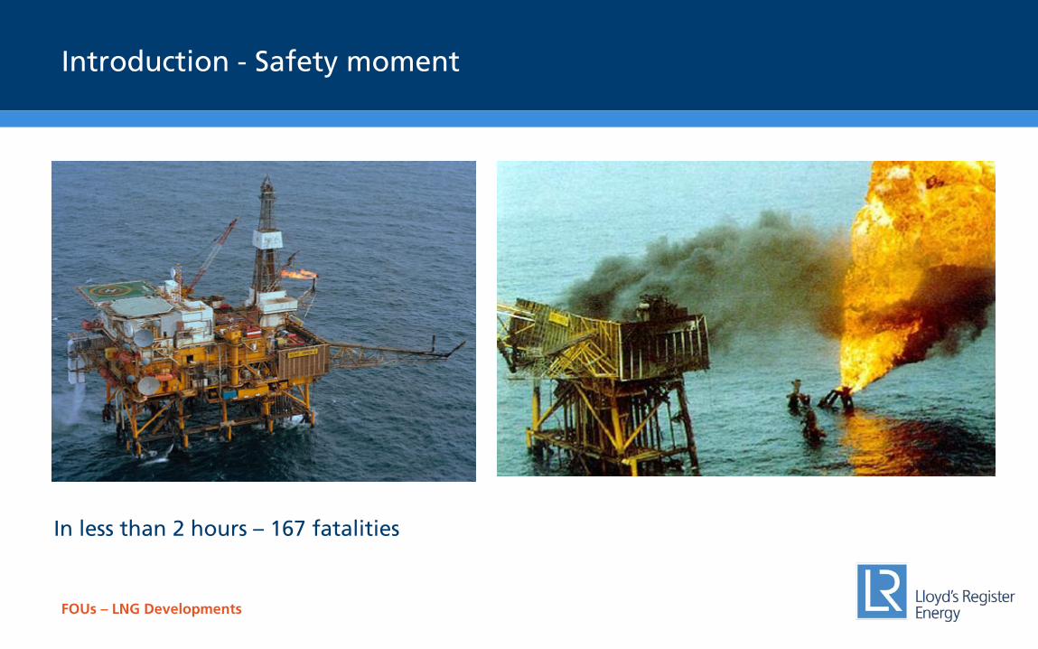
Introduction - Safety moment
In less than 2 hours – 167 fatalities
FOUs – LNG Developments
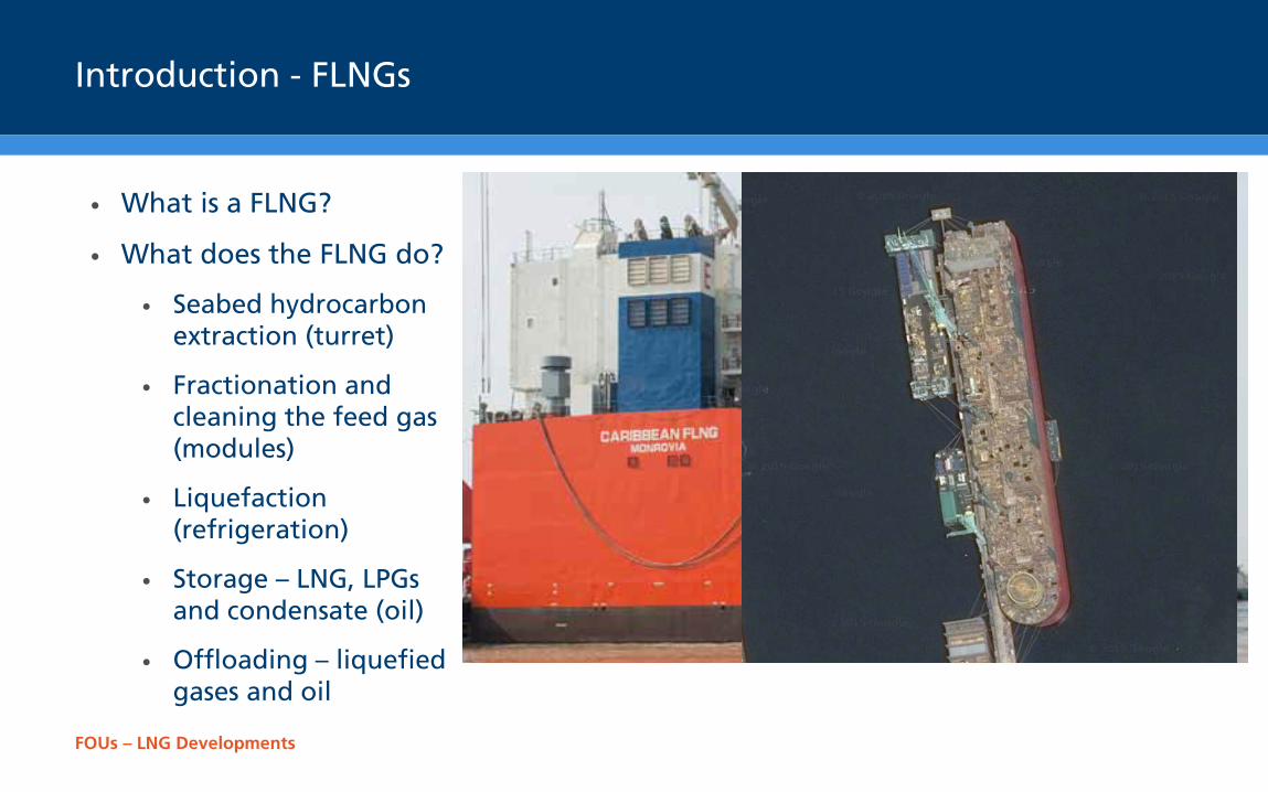
Introduction - FLNGs
• What is a FLNG?
• What does the FLNG do?
• Seabed hydrocarbon extraction (turret)
• Fractionation and cleaning the feed gas (modules)
• Liquefaction (refrigeration)
• Storage – LNG, LPGs and condensate (oil)
• Offloading – liquefied gases and oil
FOUs – LNG Developments
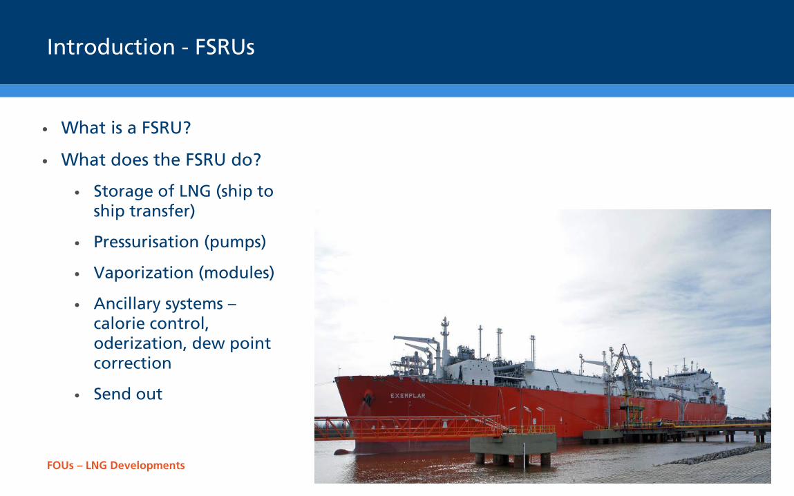
Introduction - FSRUs
• What is a FSRU?
• What does the FSRU do?
• Storage of LNG (ship to ship transfer)
• Pressurisation (pumps)
• Vaporization (modules)
• Ancillary systems – calorie control, oderization, dew point correction
• Send out
FOUs – LNG Developments
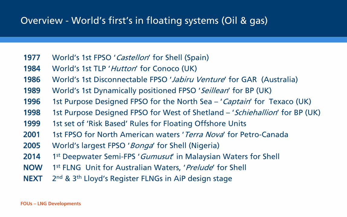
Overview - World’s first’s in floating systems (Oil & gas)
1977 World’s 1st FPSO ‘Castellon’ for Shell (Spain) 1984 World’s 1st TLP ‘Hutton’ for Conoco (UK) 1986 World’s 1st Disconnectable FPSO ‘Jabiru Venture’ for GAR (Australia) 1989 World’s 1st Dynamically positioned FPSO ‘Seillean’ for BP (UK) 1996 1st Purpose Designed FPSO for the North Sea – ‘Captain’ for Texaco (UK) 1998 1st Purpose Designed FPSO for West of Shetland – ‘Schiehallion’ for BP (UK) 1999 1st set of ‘Risk Based’ Rules for Floating Offshore Units 2001 1st FPSO for North American waters ‘Terra Nova’ for Petro-Canada 2005 World’s largest FPSO ‘Bonga’ for Shell (Nigeria) 2014 1st Deepwater Semi-FPS ‘Gumusut’ in Malaysian Waters for Shell NOW 1st FLNG Unit for Australian Waters, ‘Prelude’ for Shell NEXT 2nd & 3th Lloyd’s Register FLNGs in AiP design stage
FOUs – LNG Developments
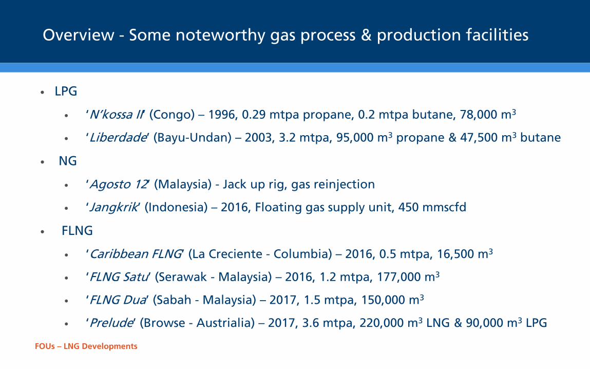
Overview - Some noteworthy gas process & production facilities
• LPG
• ‘N’kossa II’ (Congo) – 1996, 0.29 mtpa propane, 0.2 mtpa butane, 78,000 m3
• ‘Liberdade’ (Bayu-Undan) – 2003, 3.2 mtpa, 95,000 m3 propane & 47,500 m3 butane
• NG
• ‘Agosto 12’ (Malaysia) - Jack up rig, gas reinjection
• ‘Jangkrik’ (Indonesia) – 2016, Floating gas supply unit, 450 mmscfd
• FLNG
• ‘Caribbean FLNG’ (La Creciente - Columbia) – 2016, 0.5 mtpa, 16,500 m3
• ‘FLNG Satu’ (Serawak - Malaysia) – 2016, 1.2 mtpa, 177,000 m3
• ‘FLNG Dua’ (Sabah - Malaysia) – 2017, 1.5 mtpa, 150,000 m3
• ‘Prelude’ (Browse - Austrialia) – 2017, 3.6 mtpa, 220,000 m3 LNG & 90,000 m3 LPG
FOUs – LNG Developments
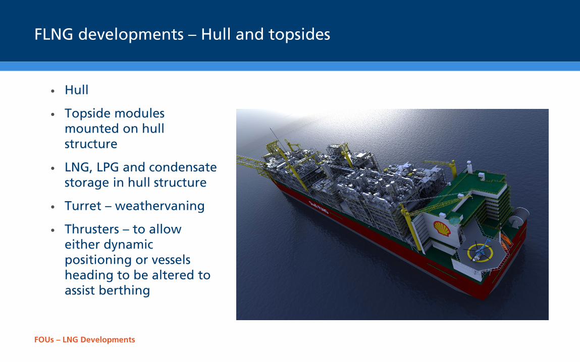
FLNG developments – Hull and topsides
• Hull
• Topside modules mounted on hull structure
• LNG, LPG and condensate storage in hull structure
• Turret – weathervaning
• Thrusters – to allow either dynamic positioning or vessels heading to be altered to assist berthing
FOUs – LNG Developments
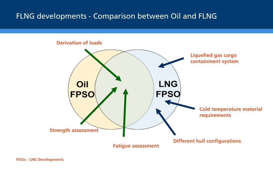
FLNG developments - Comparison between Oil and FLNG
Derivation of loads
Strength assessment
Fatigue assessment
Cold temperature material requirements
Liquefied gas cargo containment system
Different hull configurations
FOUs – LNG Developments
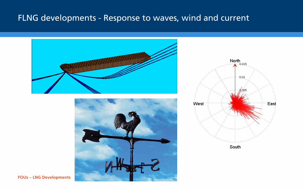
FLNG developments - Response to waves, wind and current
FOUs – LNG Developments
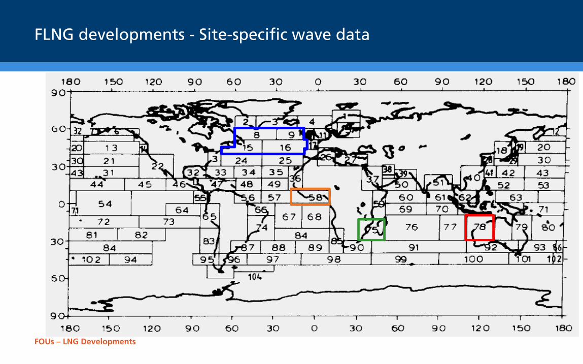
FLNG developments - Site-specific wave data
FOUs – LNG Developments
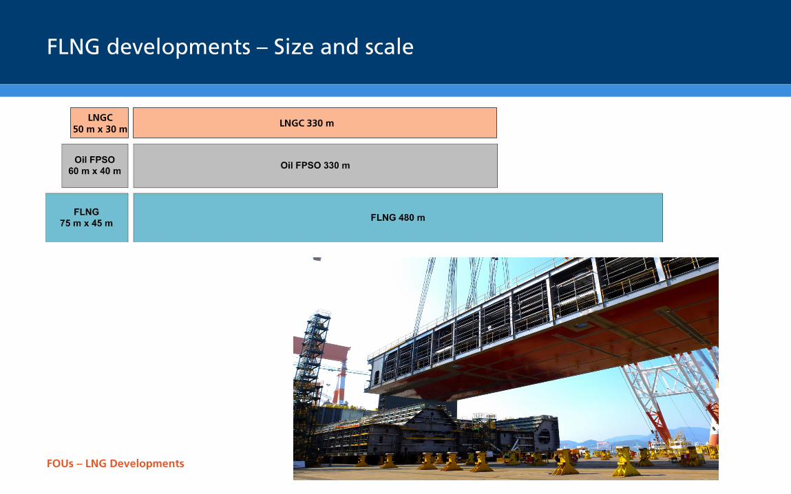
FLNG developments – Size and scale
LNGC 50 m x 30 m
LNGC 330 m
FOUs – LNG Developments
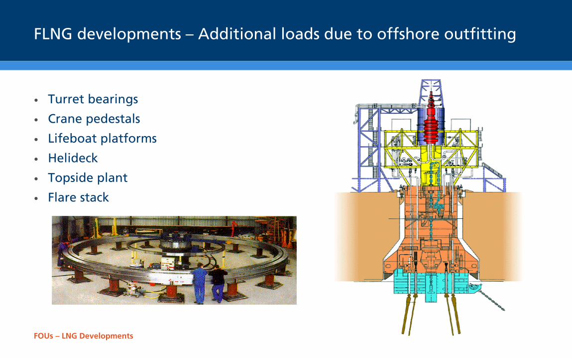
FLNG developments – Additional loads due to offshore outfitting
• Turret bearings
• Crane pedestals
• Lifeboat platforms
• Helideck
• Topside plant
• Flare stack
FOUs – LNG Developments
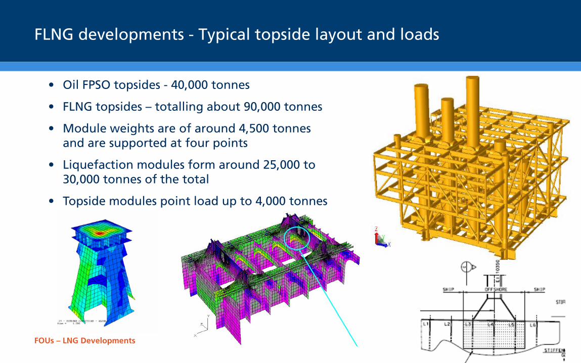
FLNG developments - Typical topside layout and loads
• Oil FPSO topsides - 40,000 tonnes
• FLNG topsides – totalling about 90,000 tonnes
• Module weights are of around 4,500 tonnes and are supported at four points
• Liquefaction modules form around 25,000 to 30,000 tonnes of the total
• Topside modules point load up to 4,000 tonnes
FOUs – LNG Developments
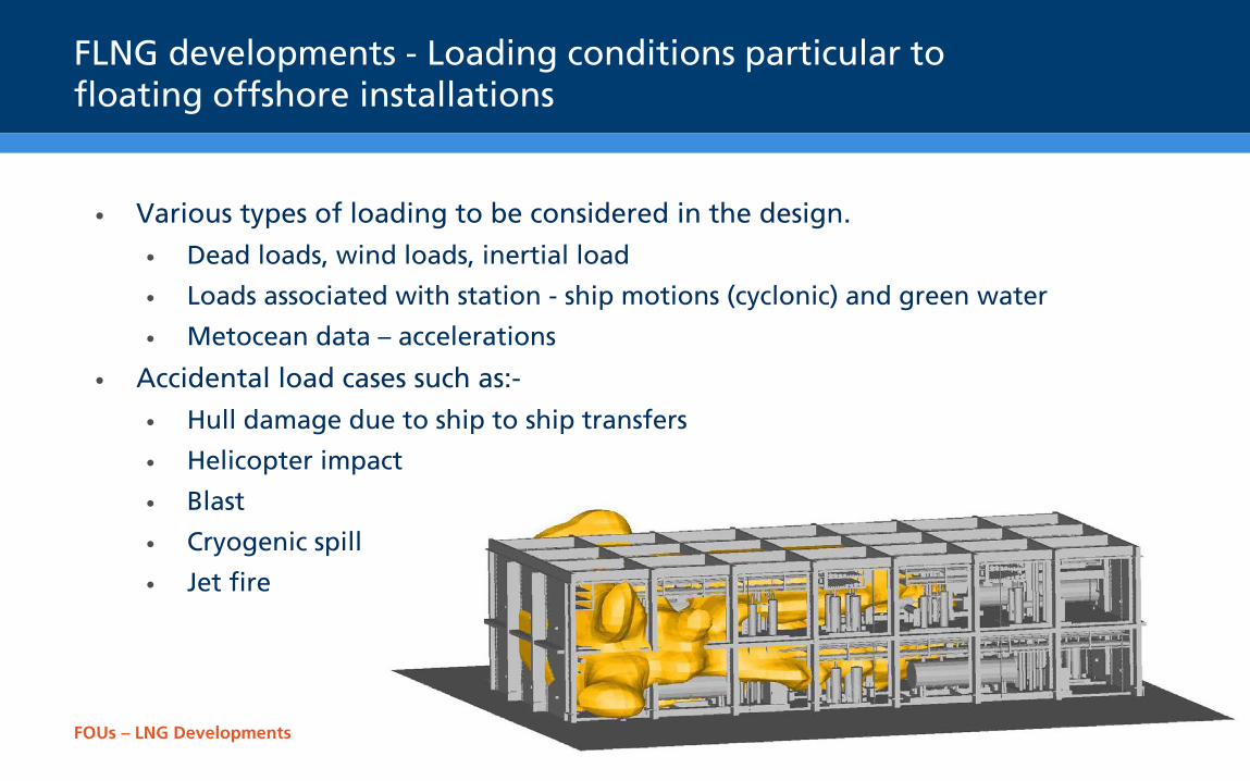
FLNG developments - Loading conditions particular to floating offshore installations
• Various types of loading to be considered in the design.
• Dead loads, wind loads, inertial load
• Loads associated with station - ship motions (cyclonic) and green water
• Metocean data – accelerations
• Accidental load cases such as:-
• Hull damage due to ship to ship transfers
• Helicopter impact
• Blast
• Cryogenic spill
• Jet fire
FOUs – LNG Developments
FLNG developments - Floating offshore installations loadings
• Acceptance criteria under extreme or accidental load case • Similar to trading oil and LNG gas tankers – some differences in accidental
load cases but significant differences in weights and masses
• Location specific
• Operating condition = 1 year return period
• Extreme condition = 100 year return period
• Abnormal condition = 10,000 year return period
• Damage condition = 1 year return period with hull damage
• Partial filling
• Tanks may well be in the normal barred filling range defined by tank designer
FOUs – LNG Developments
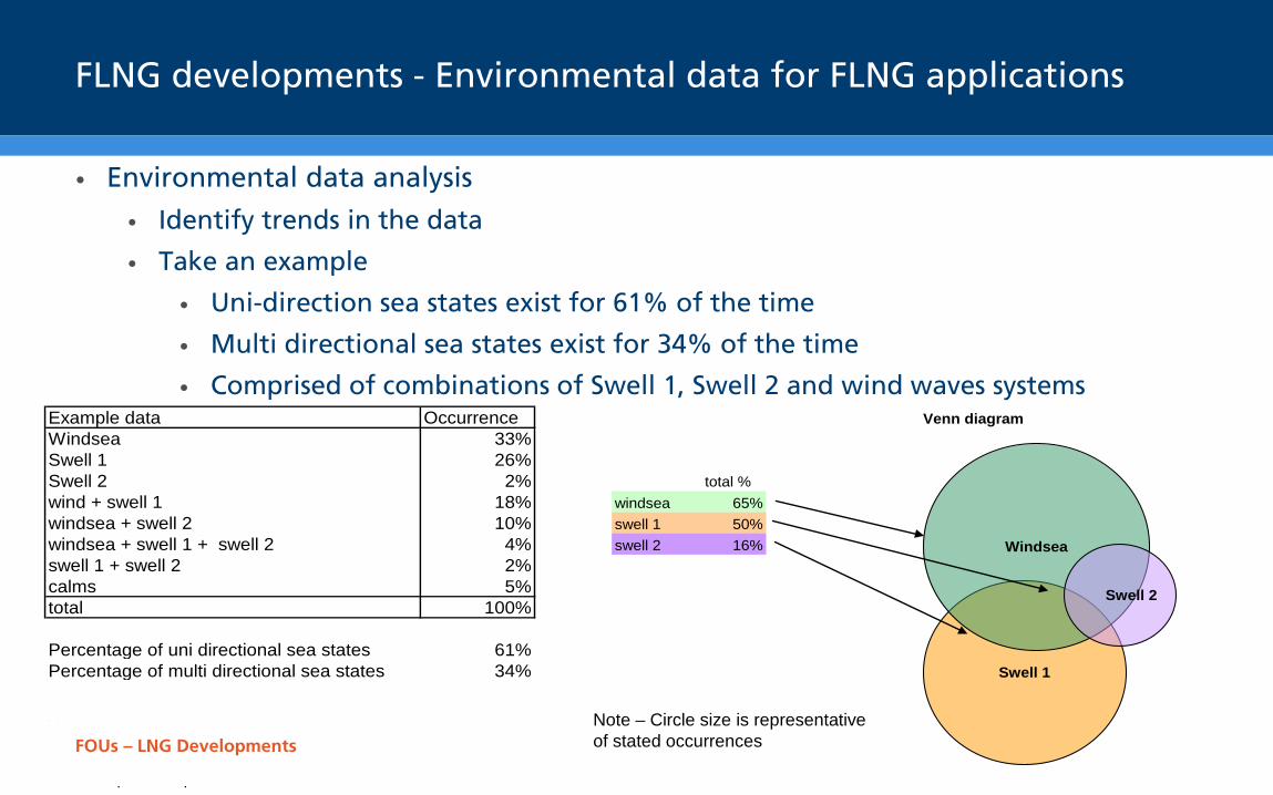
FLNG developments - Environmental data for FLNG applications
• Environmental data analysis
• Identify trends in the data
• Take an example
• Uni-direction sea states exist for 61% of the time
• Multi directional sea states exist for 34% of the time
• Comprised of combinations of Swell 1, Swell 2 and wind waves systems Example data Occurrence Venn diagramWindsea 33%Swell 1 26%Swell 2 2% total %wind + swell 1 18% windsea 65%windsea + swell 2 10% swell 1 50%windsea + swell 1 + swell 2 4% swell 2 16%swell 1 + swell 2 2%calms 5%total 100%
Percentage of uni directional sea states 61%Percentage of multi directional sea states 34%
Notescircles are the correct sizeoverlaps are approximaterelationships are as per the data
Swell 1
Windsea
Swell 2
Note – Circle size is representative of stated occurrences FOUs – LNG Developments

FOUs – LNG Developments
FLNG developments - Sloshing assessment of uni-directional seas
• Stage 1 Sloshing assessment - uni-directional seas
• For the portion of the environmental data that is predominantly uni-directional waves
• For this example:
• Uni-directional = 61% of the time
• Treat uni-directional waves as per normal ship sloshing assessment
• This applies to the swell seas as well as the wind sea
• Can use short term or long term assessment methods
FOUs – LNG Developments
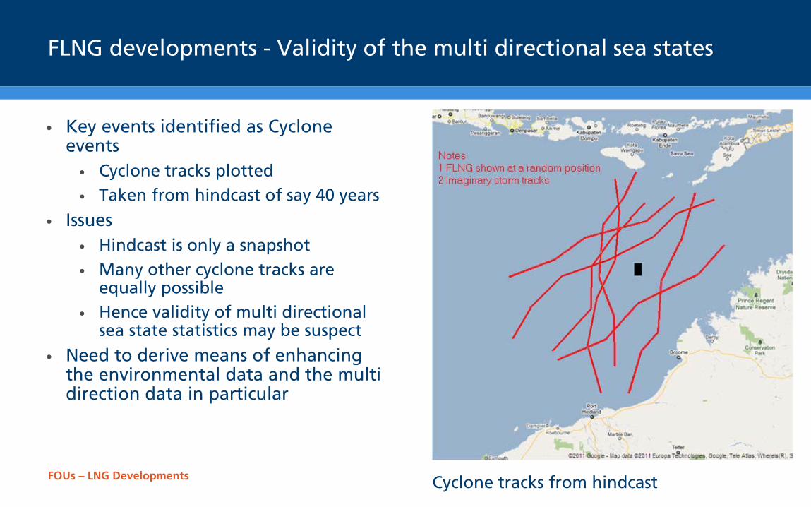
FLNG developments - Validity of the multi directional sea states
• Key events identified as Cyclone events • Cyclone tracks plotted • Taken from hindcast of say 40 years
• Issues • Hindcast is only a snapshot • Many other cyclone tracks are
equally possible • Hence validity of multi directional
sea state statistics may be suspect
• Need to derive means of enhancing the environmental data and the multi direction data in particular
Cyclone tracks from hindcast
FOUs – LNG Developments
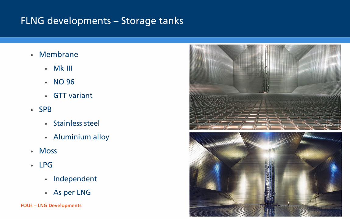
FLNG developments – Storage tanks
• Membrane
• Mk III
• NO 96
• GTT variant
• SPB
• Stainless steel
• Aluminium alloy
• Moss
• LPG
• Independent
• As per LNG
FOUs – LNG Developments
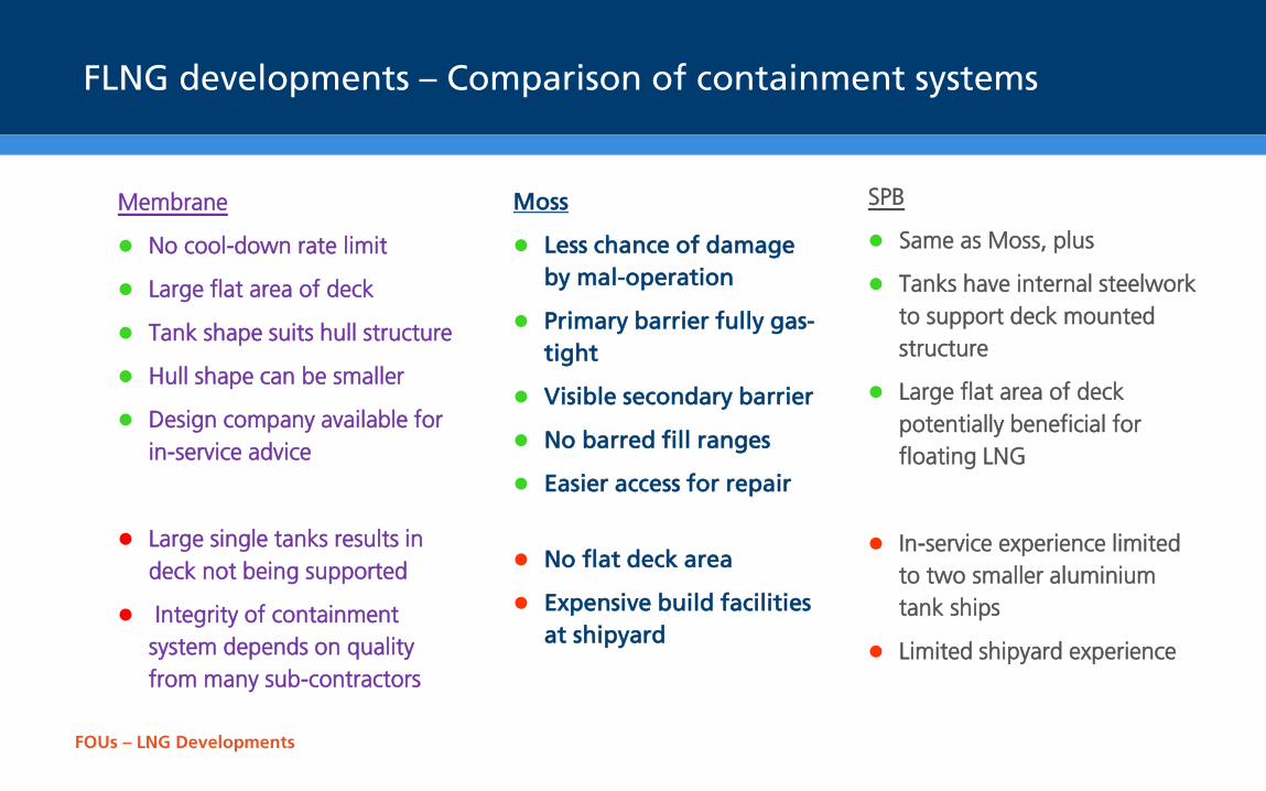
FLNG developments – Comparison of containment systems
Moss
Less chance of damage by mal-operation
Primary barrier fully gas-tight
Visible secondary barrier
No barred fill ranges
Easier access for repair
No flat deck area
Expensive build facilities at shipyard
Membrane
No cool-down rate limit
Large flat area of deck
Tank shape suits hull structure
Hull shape can be smaller
Design company available for in-service advice
Large single tanks results in deck not being supported
Integrity of containment system depends on quality from many sub-contractors
SPB
Same as Moss, plus
Tanks have internal steelwork to support deck mounted structure
Large flat area of deck potentially beneficial for floating LNG
In-service experience limited to two smaller aluminium tank ships
Limited shipyard experience
FOUs – LNG Developments
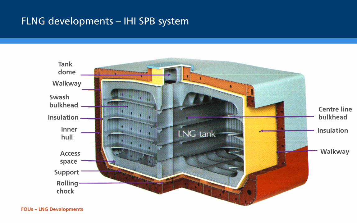
Insulation
Walkway
Centre line bulkhead
Tank dome
Walkway
Swash bulkhead
Insulation
Inner hull
Access space
Support
Rolling chock
FLNG developments – IHI SPB system
FOUs – LNG Developments
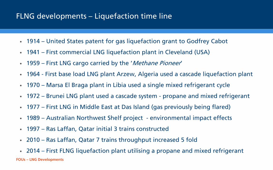
FLNG developments – Liquefaction time line
• 1914 – United States patent for gas liquefaction grant to Godfrey Cabot
• 1941 – First commercial LNG liquefaction plant in Cleveland (USA)
• 1959 – First LNG cargo carried by the ‘Methane Pioneer’
• 1964 - First base load LNG plant Arzew, Algeria used a cascade liquefaction plant
• 1970 – Marsa El Braga plant in Libia used a single mixed refrigerant cycle
• 1972 – Brunei LNG plant used a cascade system - propane and mixed refrigerant
• 1977 – First LNG in Middle East at Das Island (gas previously being flared)
• 1989 – Australian Northwest Shelf project - environmental impact effects
• 1997 – Ras Laffan, Qatar initial 3 trains constructed
• 2010 – Ras Laffan, Qatar 7 trains throughput increased 5 fold
• 2014 – First FLNG liquefaction plant utilising a propane and mixed refrigerant
FOUs – LNG Developments
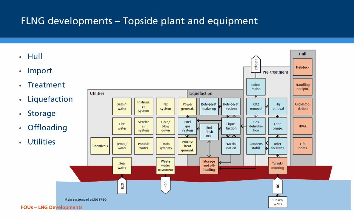
FLNG developments – Topside plant and equipment
• Hull
• Import
• Treatment
• Liquefaction
• Storage
• Offloading
• Utilities
FOUs – LNG Developments
FOUs – LNG Developments
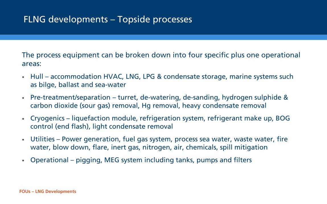
FLNG developments – Topside processes
The process equipment can be broken down into four specific plus one operational areas:
• Hull – accommodation HVAC, LNG, LPG & condensate storage, marine systems such as bilge, ballast and sea-water
• Pre-treatment/separation – turret, de-watering, de-sanding, hydrogen sulphide & carbon dioxide (sour gas) removal, Hg removal, heavy condensate removal
• Cryogenics – liquefaction module, refrigeration system, refrigerant make up, BOG control (end flash), light condensate removal
• Utilities – Power generation, fuel gas system, process sea water, waste water, fire water, blow down, flare, inert gas, nitrogen, air, chemicals, spill mitigation
• Operational – pigging, MEG system including tanks, pumps and filters
FOUs – LNG Developments
FLNG developments – Liquefaction cycles
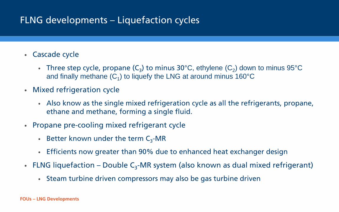
• Cascade cycle
• Three step cycle, propane (C3) to minus 30°C, ethylene (C2) down to minus 95°C and finally methane (C1) to liquefy the LNG at around minus 160°C
• Mixed refrigeration cycle
• Also know as the single mixed refrigeration cycle as all the refrigerants, propane, ethane and methane, forming a single fluid.
• Propane pre-cooling mixed refrigerant cycle
• Better known under the term C3-MR
• Efficients now greater than 90% due to enhanced heat exchanger design
• FLNG liquefaction – Double C3-MR system (also known as dual mixed refrigerant)
• Steam turbine driven compressors may also be gas turbine driven
FOUs – LNG Developments
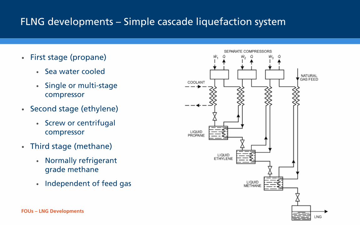
FLNG developments – Simple cascade liquefaction system
• First stage (propane)
• Sea water cooled
• Single or multi-stage compressor
• Second stage (ethylene)
• Screw or centrifugal compressor
• Third stage (methane)
• Normally refrigerant grade methane
• Independent of feed gas
FOUs – LNG Developments
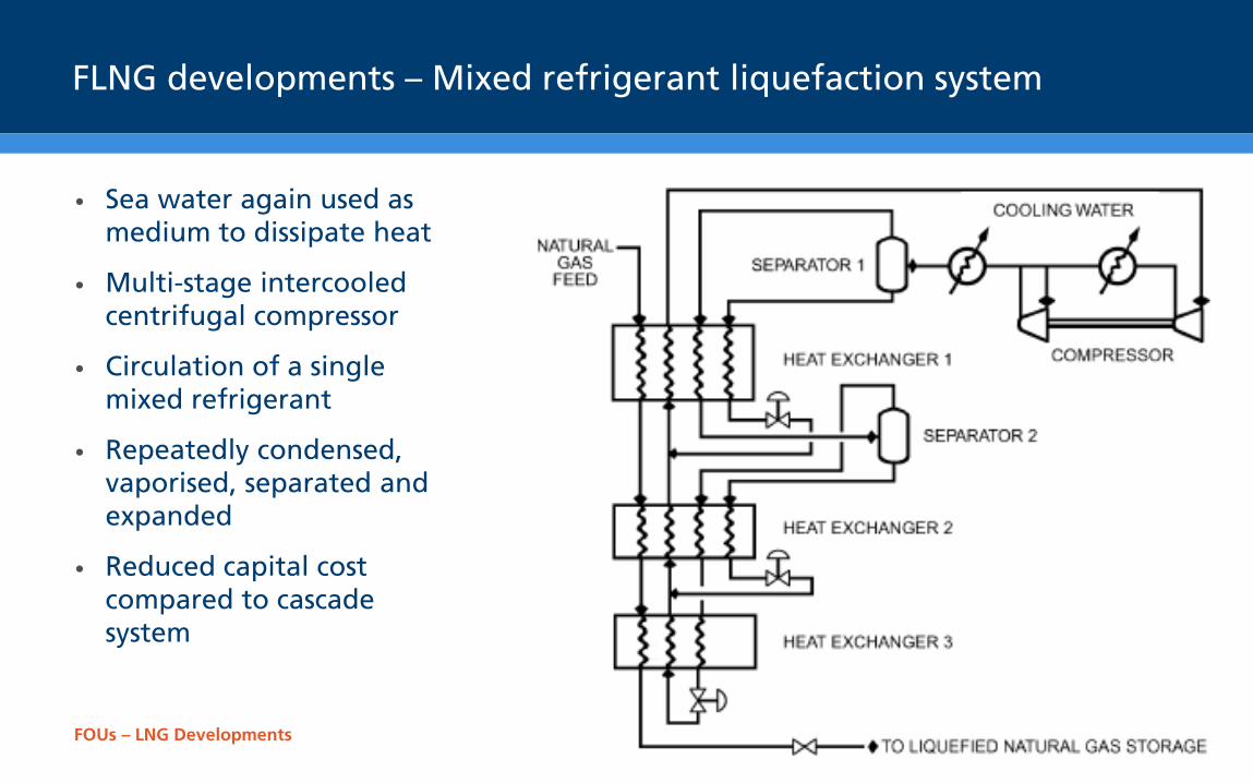
FLNG developments – Mixed refrigerant liquefaction system
• Sea water again used as medium to dissipate heat
• Multi-stage intercooled centrifugal compressor
• Circulation of a single mixed refrigerant
• Repeatedly condensed, vaporised, separated and expanded
• Reduced capital cost compared to cascade system
FOUs – LNG Developments
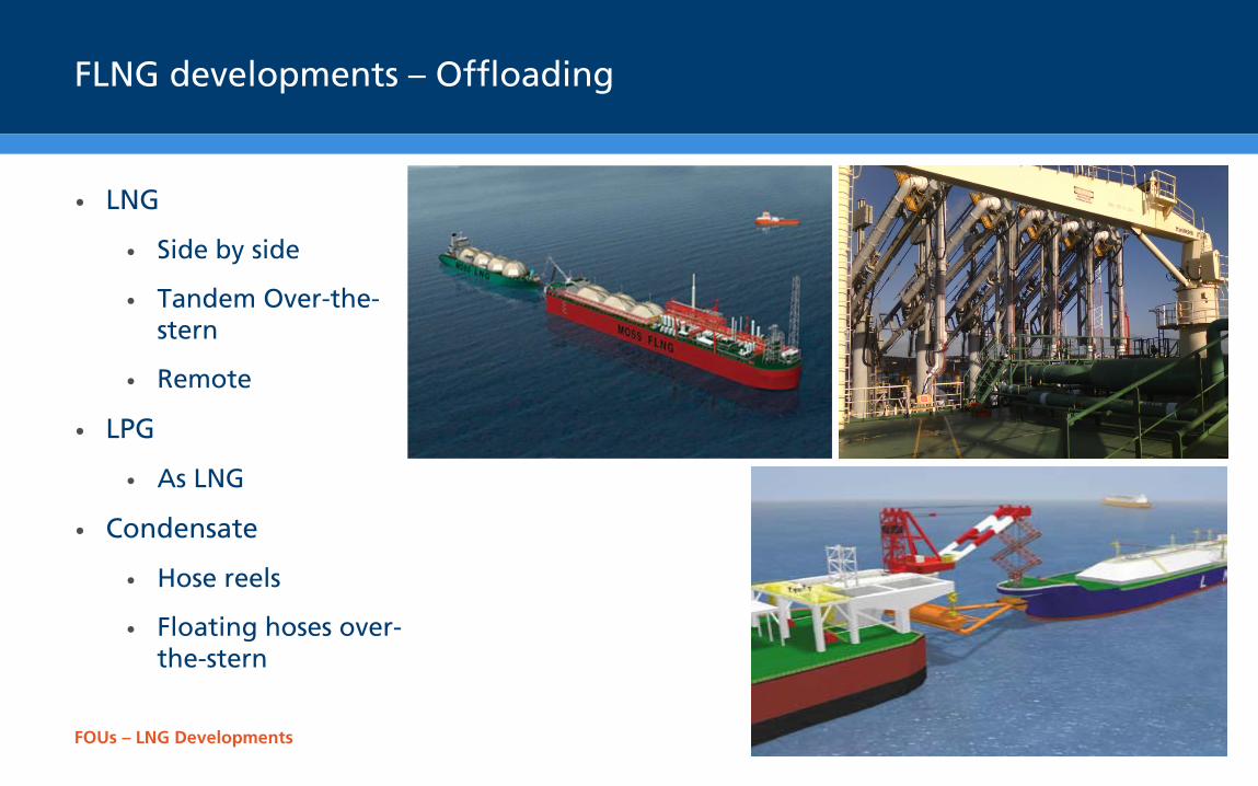
FLNG developments – Offloading
• LNG
• Side by side
• Tandem Over-the-stern
• Remote
• LPG
• As LNG
• Condensate
• Hose reels
• Floating hoses over- the-stern
FOUs – LNG Developments
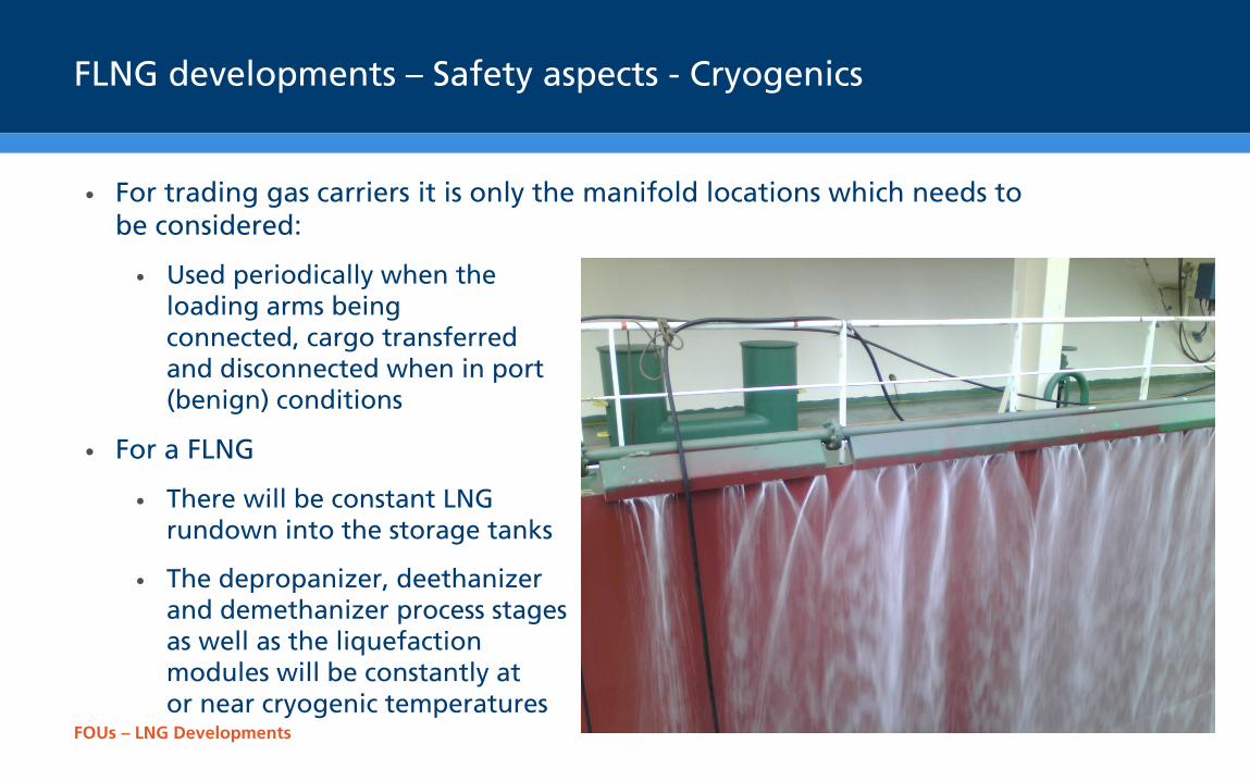
FLNG developments – Safety aspects - Cryogenics
• For trading gas carriers it is only the manifold locations which needs to be considered:
• Used periodically when the loading arms being connected, cargo transferred and disconnected when in port (benign) conditions
• For a FLNG
• There will be constant LNG rundown into the storage tanks
• The depropanizer, deethanizer and demethanizer process stages as well as the liquefaction modules will be constantly at or near cryogenic temperatures
FOUs – LNG Developments
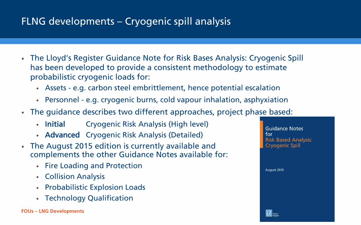
FLNG developments – Cryogenic spill analysis
• The Lloyd’s Register Guidance Note for Risk Bases Analysis: Cryogenic Spill has been developed to provide a consistent methodology to estimate probabilistic cryogenic loads for: • Assets - e.g. carbon steel embrittlement, hence potential escalation
• Personnel - e.g. cryogenic burns, cold vapour inhalation, asphyxiation
• The guidance describes two different approaches, project phase based:
• Initial Cryogenic Risk Analysis (High level) • Advanced Cryogenic Risk Analysis (Detailed)
• The August 2015 edition is currently available and complements the other Guidance Notes available for: • Fire Loading and Protection • Collision Analysis • Probabilistic Explosion Loads • Technology Qualification
FOUs – LNG Developments
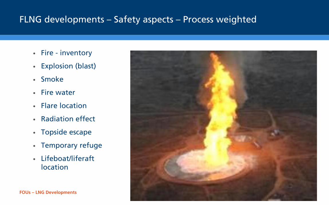
FLNG developments – Safety aspects – Process weighted
• Fire - inventory
• Explosion (blast)
• Smoke
• Fire water
• Flare location
• Radiation effect
• Topside escape
• Temporary refuge
• Lifeboat/liferaft location
FOUs – LNG Developments
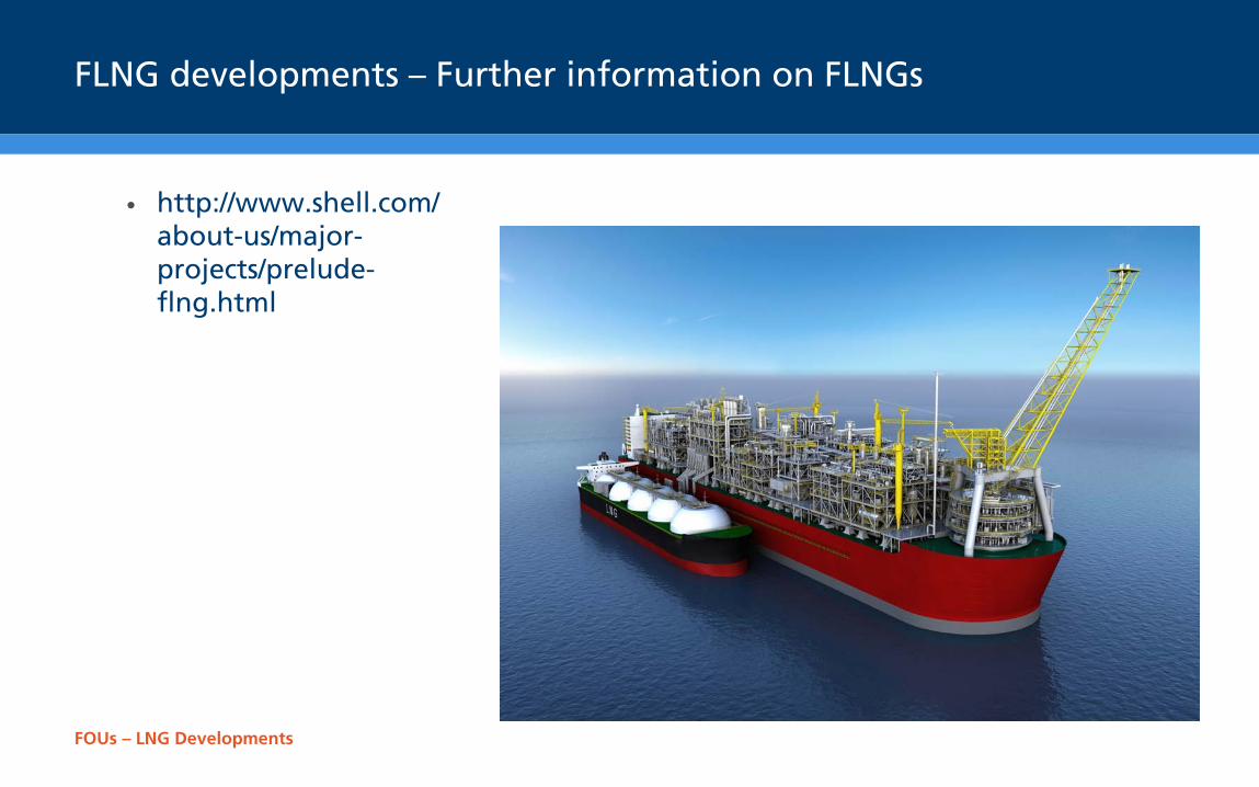
FLNG developments – Further information on FLNGs
• http://www.shell.com/about-us/major-projects/prelude-flng.html
FOUs – LNG Developments
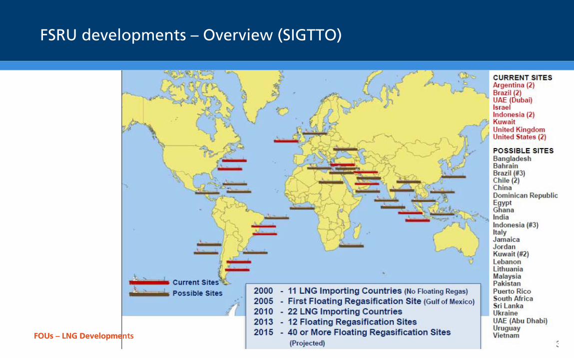
FSRU developments – Overview (SIGTTO)
FOUs – LNG Developments
FOUs – LNG Developments
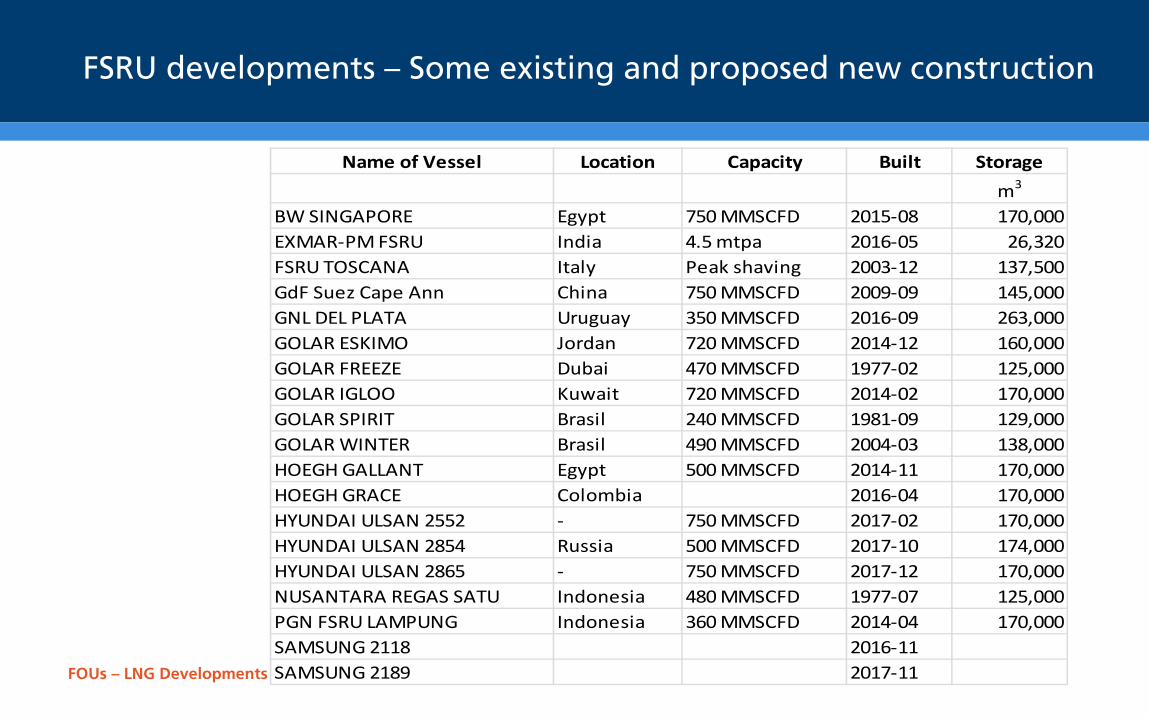
FSRU developments – Some existing and proposed new construction
Name of Vessel Location Capacity Built Storagem3
BW SINGAPORE Egypt 750 MMSCFD 2015-08 170,000EXMAR-PM FSRU India 4.5 mtpa 2016-05 26,320FSRU TOSCANA Italy Peak shaving 2003-12 137,500GdF Suez Cape Ann China 750 MMSCFD 2009-09 145,000GNL DEL PLATA Uruguay 350 MMSCFD 2016-09 263,000GOLAR ESKIMO Jordan 720 MMSCFD 2014-12 160,000GOLAR FREEZE Dubai 470 MMSCFD 1977-02 125,000GOLAR IGLOO Kuwait 720 MMSCFD 2014-02 170,000GOLAR SPIRIT Brasil 240 MMSCFD 1981-09 129,000GOLAR WINTER Brasil 490 MMSCFD 2004-03 138,000HOEGH GALLANT Egypt 500 MMSCFD 2014-11 170,000HOEGH GRACE Colombia 2016-04 170,000HYUNDAI ULSAN 2552 - 750 MMSCFD 2017-02 170,000HYUNDAI ULSAN 2854 Russia 500 MMSCFD 2017-10 174,000HYUNDAI ULSAN 2865 - 750 MMSCFD 2017-12 170,000NUSANTARA REGAS SATU Indonesia 480 MMSCFD 1977-07 125,000PGN FSRU LAMPUNG Indonesia 360 MMSCFD 2014-04 170,000SAMSUNG 2118 2016-11SAMSUNG 2189 2017-11
FOUs – LNG Developments
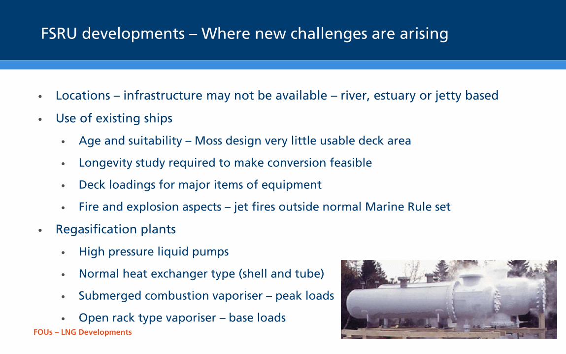
FSRU developments – Where new challenges are arising
• Locations – infrastructure may not be available – river, estuary or jetty based
• Use of existing ships
• Age and suitability – Moss design very little usable deck area
• Longevity study required to make conversion feasible
• Deck loadings for major items of equipment
• Fire and explosion aspects – jet fires outside normal Marine Rule set
• Regasification plants
• High pressure liquid pumps
• Normal heat exchanger type (shell and tube)
• Submerged combustion vaporiser – peak loads
• Open rack type vaporiser – base loads
FOUs – LNG Developments
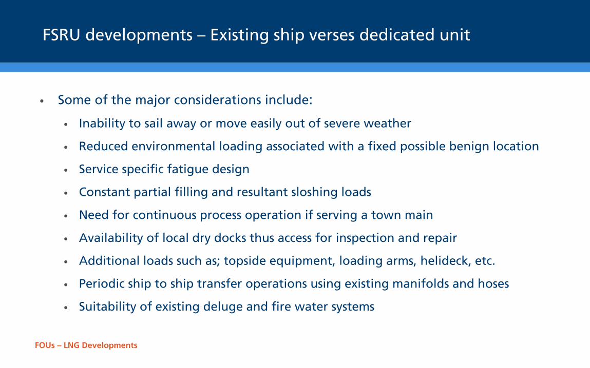
FSRU developments – Existing ship verses dedicated unit
• Some of the major considerations include:
• Inability to sail away or move easily out of severe weather
• Reduced environmental loading associated with a fixed possible benign location
• Service specific fatigue design
• Constant partial filling and resultant sloshing loads
• Need for continuous process operation if serving a town main
• Availability of local dry docks thus access for inspection and repair
• Additional loads such as; topside equipment, loading arms, helideck, etc.
• Periodic ship to ship transfer operations using existing manifolds and hoses
• Suitability of existing deluge and fire water systems
FOUs – LNG Developments
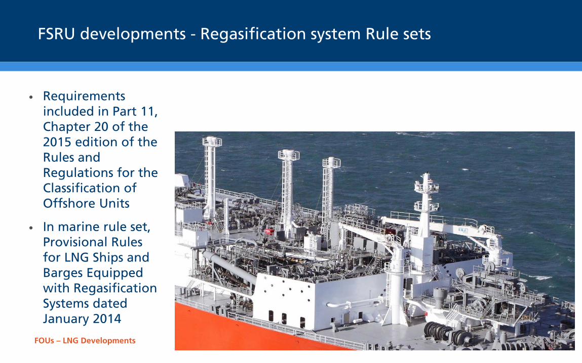
FSRU developments - Regasification system Rule sets
• Requirements included in Part 11, Chapter 20 of the 2015 edition of the Rules and Regulations for the Classification of Offshore Units
• In marine rule set, Provisional Rules for LNG Ships and Barges Equipped with Regasification Systems dated January 2014
FOUs – LNG Developments
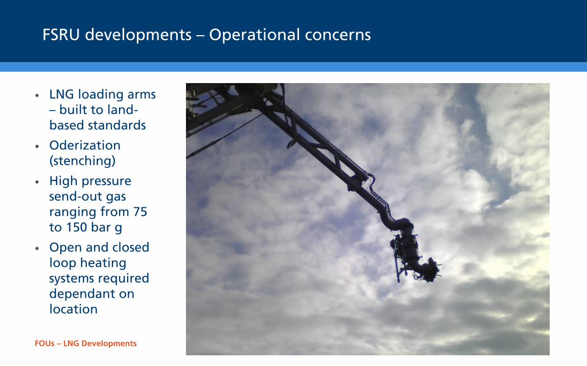
FSRU developments – Operational concerns
• LNG loading arms – built to land-based standards
• Oderization (stenching)
• High pressure send-out gas ranging from 75 to 150 bar g
• Open and closed loop heating systems required dependant on location
FOUs – LNG Developments
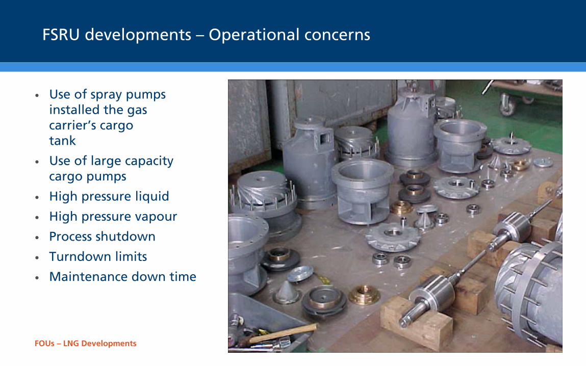
FSRU developments – Operational concerns
• Use of spray pumps installed the gas carrier’s cargo tank
• Use of large capacity cargo pumps
• High pressure liquid
• High pressure vapour
• Process shutdown
• Turndown limits
• Maintenance down time
FOUs – LNG Developments
FLNG & FSRU developments – Maintenance concerns
• Normal periodic dry docking and complete gas freeing not envisaged as an option:
• Extensions to normal shut down periodicity
• Sparing philosophies to take into consideration regarding maintenance requirements
• Consideration to be given to the circulating fluid
• Corrosion protection system to be enhanced
• High cost due to send-out shutdown if extensive hot work required
• Gas freeing of individual tanks under a local ‘Permit to Work’ system a possible option
• Retractable cargo pumps so tank entry is not required
• Method of ship to ship transfer – Loading arms maintenance or replacement hoses
• RBI (Risk Based Inspection) – For entire unit either FLNG or FSRU
FOUs – LNG Developments
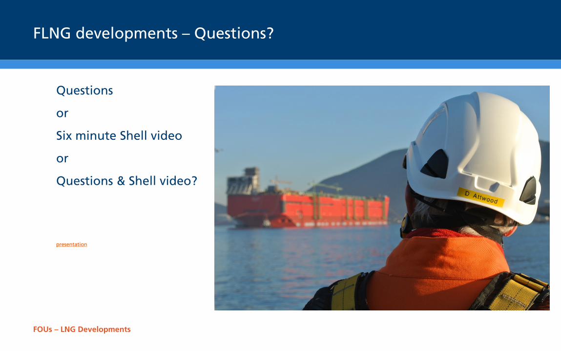
FLNG developments – Questions?
Questions
or
Six minute Shell video
or
Questions & Shell video?
presentation
Lloyd’s Register EMEA (Reg. no. 29592 R) is a registered society under the Co-operative and Community Benefit Societies Act 2014 in England and Wales. Registered office: 71 Fenchurch Street, London, EC3M 4BS, UK. A member of the Lloyd’s Register group
Robbie Sillars Principal Specialist – Refrigeration Energy Compliance Services T +44 (0)20 7423 1921 E [email protected] Lloyd’s Register Group Services Ltd. 71 Fenchurch Street, London EC3M 4BS
Working together for a safer world