Embed Size (px)
Citation preview
Owner’s Manual
Fox Body Mustang
21 www.EPASPerformance.com 1-941-893-5427
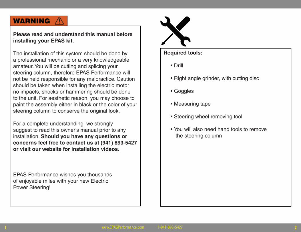
WARNING
Please read and understand this manual before installing your EPAS kit.
The installation of this system should be done by a professional mechanic or a very knowledgeable amateur. You will be cutting and splicing your steering column, therefore EPAS Performance will not be held responsible for any malpractice. Caution should be taken when installing the electric motor: no impacts, shocks or hammering should be done to the unit. For aesthetic reason, you may choose to paint the assembly either in black or the color of your steering column to conserve the original look.
For a complete understanding, we stronglysuggest to read this owner’s manual prior to any installation. Should you have any questions or concerns feel free to contact us at (941) 893-5427 or visit our website for installation videos.
EPAS Performance wishes you thousandsof enjoyable miles with your new Electric Power Steering!
Required tools:
• Drill
• Right angle grinder, with cutting disc
• Goggles
• Measuring tape
• Steering wheel removing tool
• You will also need hand tools to removethe steering column
43 www.EPASPerformance.com 1-941-893-5427
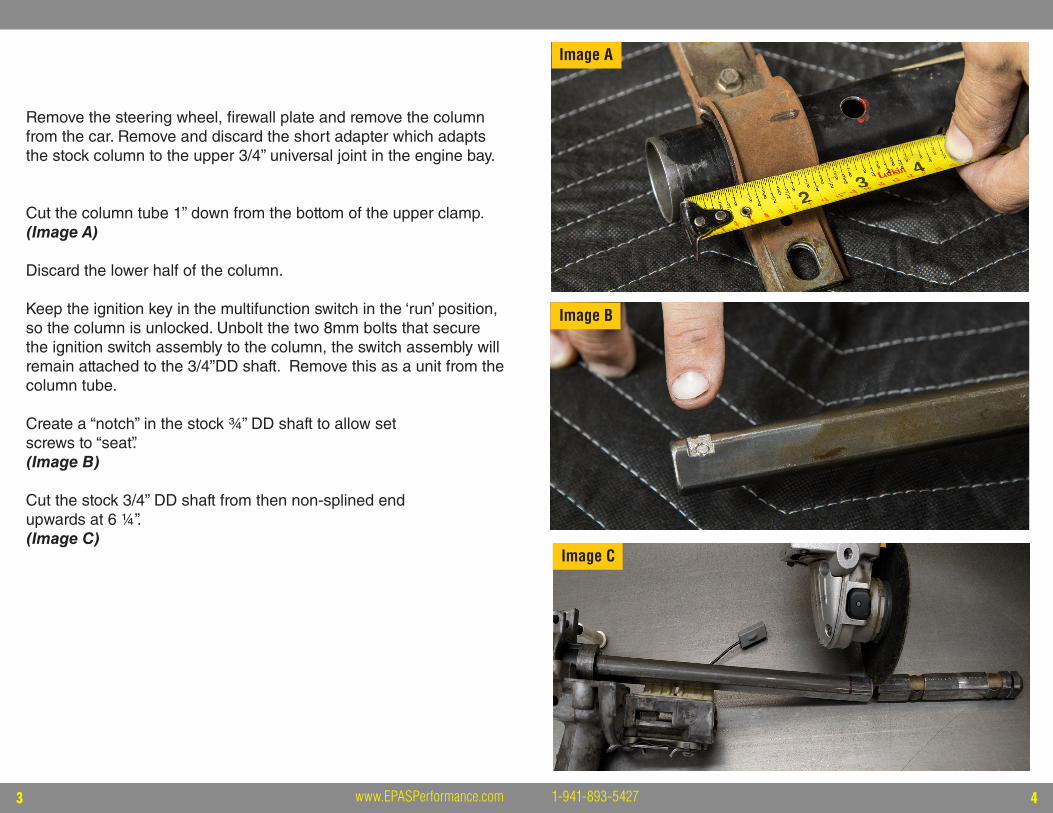
Remove the steering wheel, firewall plate and remove the column from the car. Remove and discard the short adapter which adapts the stock column to the upper 3/4” universal joint in the engine bay.
Cut the column tube 1” down from the bottom of the upper clamp. (Image A)
Discard the lower half of the column.
Keep the ignition key in the multifunction switch in the ‘run’ position, so the column is unlocked. Unbolt the two 8mm bolts that secure the ignition switch assembly to the column, the switch assembly will remain attached to the 3/4”DD shaft. Remove this as a unit from the column tube.
Create a “notch” in the stock ¾’’ DD shaft to allow set screws to “seat”.(Image B)
Cut the stock 3/4” DD shaft from then non-splined end upwards at 6 ¼’’.(Image C)
Image A
Image B
Image C
65 www.EPASPerformance.com 1-941-893-5427
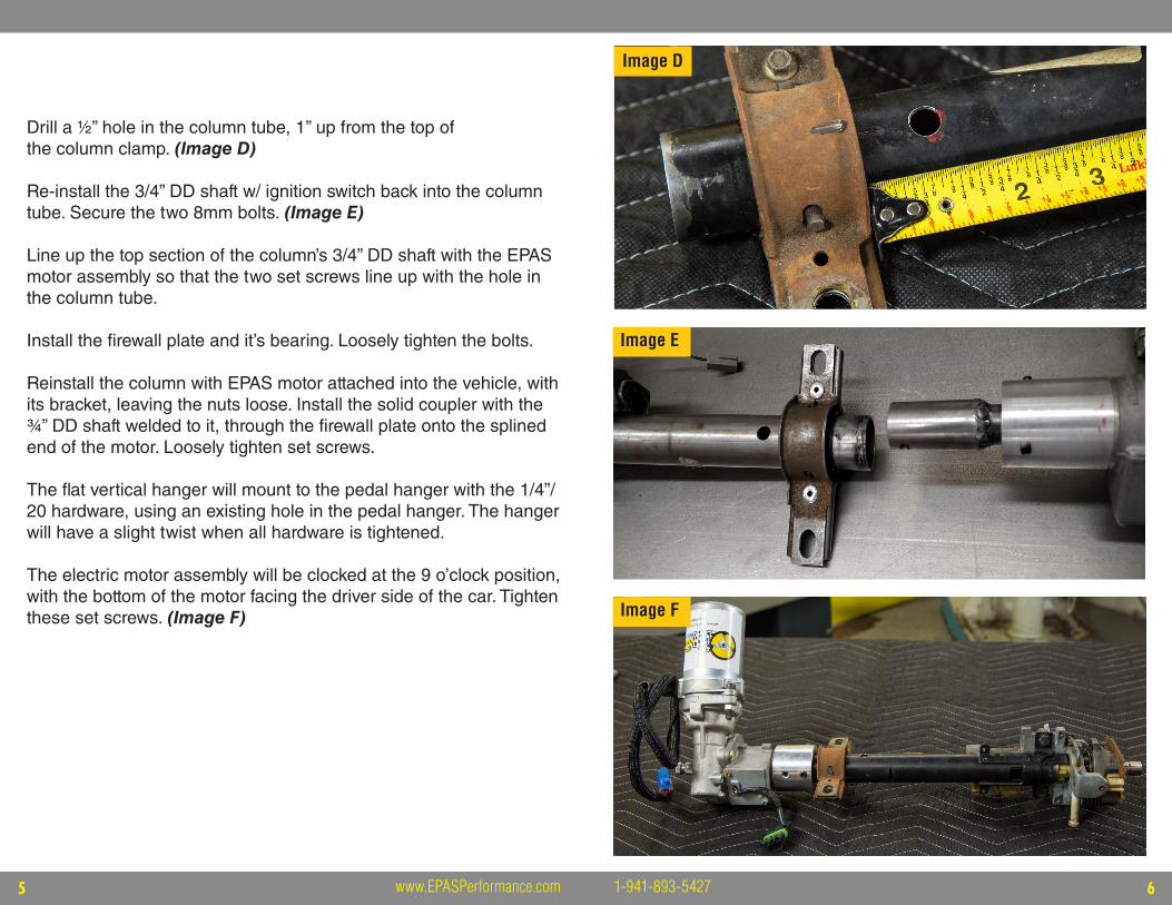
Drill a ½” hole in the column tube, 1’’ up from the top of the column clamp. (Image D)
Re-install the 3/4” DD shaft w/ ignition switch back into the column tube. Secure the two 8mm bolts. (Image E)
Line up the top section of the column’s 3/4” DD shaft with the EPAS motor assembly so that the two set screws line up with the hole in the column tube.
Install the firewall plate and it’s bearing. Loosely tighten the bolts.
Reinstall the column with EPAS motor attached into the vehicle, with its bracket, leaving the nuts loose. Install the solid coupler with the ¾’’ DD shaft welded to it, through the firewall plate onto the splined end of the motor. Loosely tighten set screws.
The flat vertical hanger will mount to the pedal hanger with the 1/4”/ 20 hardware, using an existing hole in the pedal hanger. The hanger will have a slight twist when all hardware is tightened.
The electric motor assembly will be clocked at the 9 o’clock position, with the bottom of the motor facing the driver side of the car. Tighten these set screws. (Image F) Image F
Image E
Image D
87 www.EPASPerformance.com 1-941-893-5427
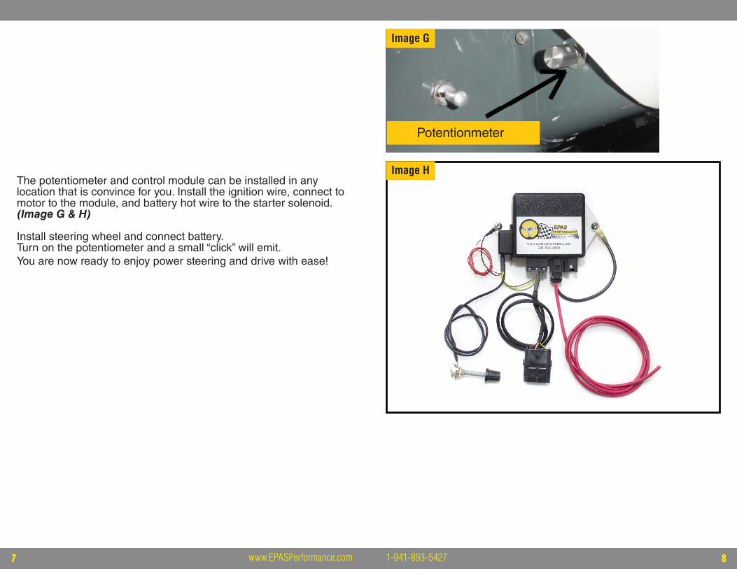
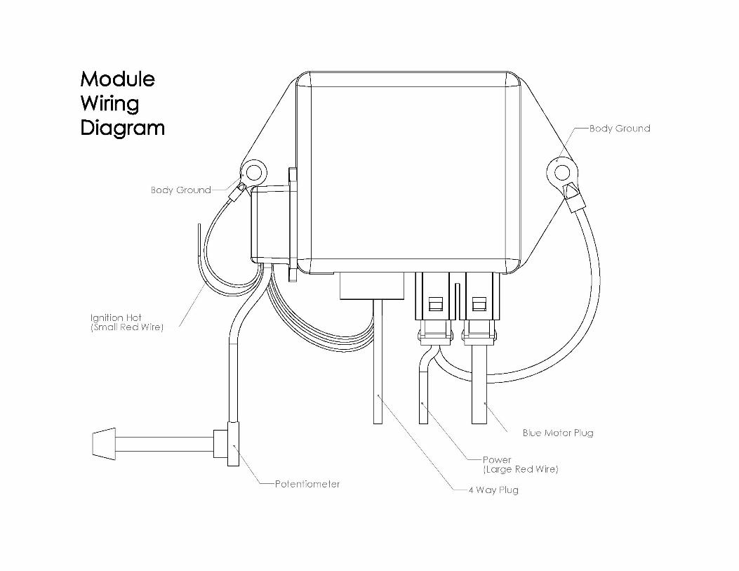
The potentiometer and control module can be installed in any location that is convince for you. Install the ignition wire, connect to motor to the module, and battery hot wire to the starter solenoid. (Image G & H)
Install steering wheel and connect battery. Turn on the potentiometer and a small “click” will emit. You are now ready to enjoy power steering and drive with ease!
Image G
Image H
Potentionmeter
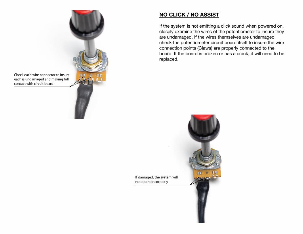
NO CLICK / NO ASSIST
If the system is not emitting a click sound when powered on, closely examine the wires of the potentiometer to insure they are undamaged. If the wires themselves are undamaged check the potentiometer circuit board itself to insure the wire connection points (Claws) are properly connected to the board. If the board is broken or has a crack, it will need to be replaced.
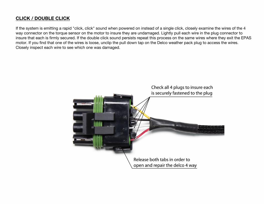
CLICK / DOUBLE CLICK
If the system is emitting a rapid "click, click" sound when powered on instead of a single click, closely examine the wires of the 4 way connector on the torque sensor on the motor to insure they are undamaged. Lightly pull each wire in the plug connector to insure that each is firmly secured. If the double click sound persists repeat this process on the same wires where they exit the EPAS motor. If you find that one of the wires is loose, unclip the pull down tap on the Delco weather pack plug to access the wires. Closely inspect each wire to see which one was damaged.
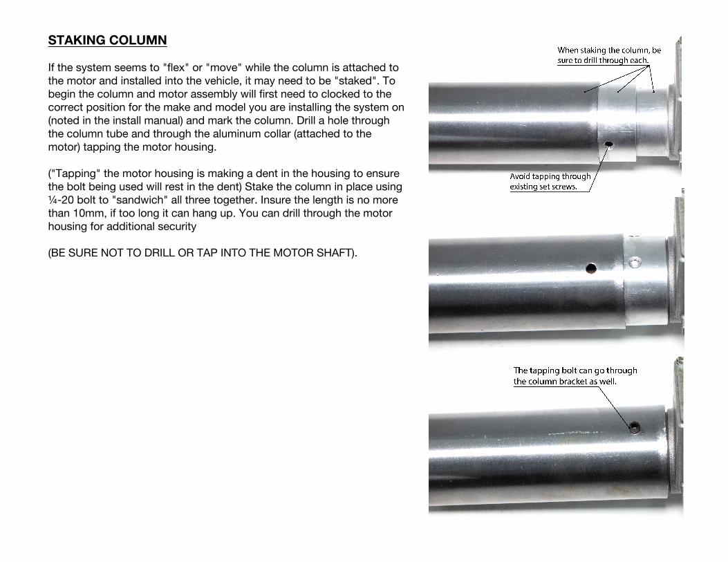
STAKING COLUMN
If the system seems to "flex" or "move" while the column is attached to the motor and installed into the vehicle, it may need to be "staked". To begin the column and motor assembly will first need to clocked to the correct position for the make and model you are installing the system on (noted in the install manual) and mark the column. Drill a hole through the column tube and through the aluminum collar (attached to the motor) tapping the motor housing.
("Tapping" the motor housing is making a dent in the housing to ensure the bolt being used will rest in the dent) Stake the column in place using ¼-20 bolt to "sandwich" all three together. Insure the length is no more than 10mm, if too long it can hang up. You can drill through the motor housing for additional security
(BE SURE NOT TO DRILL OR TAP INTO THE MOTOR SHAFT).
109 www.EPASPerformance.com 1-941-893-5427
TERMS AND CONDITIONS
LIABILITY LIMITATION AND RELEASE
We are pleased you have chosen to purchase one of our automotive specialty equipment items. Our products are carefully designed to combine performance, durability and safety, and to work in concert with the vehicle’s original equipment. As they are specialty products, however, and as both performance and safety are paramount concerns, we urge our customers to consider having the products professionally installed.
We caution the purchaser that the enhancement provided by the specialty equipment item may change the handling characteristics of the vehicle. We urge the purchaser to carefully familiarize him/herself with the vehicle’s performance characteristics with the new equipment. This should be done in a safe environment and in a safe manner.
We have no control over the quality or correctness of equipment installations performed by others, nor can we control the uses (in manner or environment) products are subjected to. Accordingly, liability on the part of EPAS Performance LLC is limited to the terms of its Express Limited Warranty.
A decision by the purchaser to retain and install the item purchased will be deemed acceptance of the specific terms of this Liability Limitation and Release.
The purchaser expressly releases and waives any claim against us for any consequential damages or injury that may arise from the use, or any malfunction, of its product. This Liability Limitation and Release binds the original purchaser, all successors in interest, and all persons to whom the product may subsequently be transferred; and the purchaser agrees to make this limitation known to all such persons. This Liability Limitation and Release is part of the consideration for the sale of the product.
This Liability Limitation and Release is governed by the laws of the State of Florida, United States of America. Any dispute regarding its terms or application is subject to arbitration in the State of Florida at the request of either party to the sale.
WARRANTY
This warranty is limited to the repair or replacement of the defective part only; the warranty specifically excludes labor or consequential damages or injury. The decision as to whether the defective part will be repaired or replaced will rest solely with the manufacturer. The warranty period begins on the date the product is shipped to you.
Full 5-year warranty nontransferable.
This warranty is void if the product is or was improperly installed, abused in any manner. Road or accident damage is not covered.
To make a claim under this warranty, call EPAS Performance to return the defective product, shipping or postage prepaid. Please include a copy of the original purchase invoice and a note describing the circumstances of the failure or malfunction.
This warranty is governed by the laws of the State of Florida, United States of America. Any dispute regarding the coverage of this warranty, its application or terms is subject to arbitration in the State of Florida.
If the purchaser disagrees with any of the terms of this warranty, please return the purchased item within three (3) business days of receipt. A decision by the purchaser to retain and install the item purchased will be deemed acceptance of the specific terms of this warranty.

www.EPASPerformance.comVisit our website for installation videos.
EPAS PERFORMANCE2111 Whitfield Park Ave
Sarasota, FL 34243
1-941-893-54271-800-372-7611
@EPASPerformance