Embed Size (px)
Citation preview
FPGA Accelerated Online Boosting for Multi-Target Tracking
Matthew Jacobsen, Pingfan Meng, Siddarth Sampangi, Ryan KastnerComputer Science & Engineering
University of California, San DiegoLa Jolla, CA, USA
{mdjacobs, pmeng, ssampang, kastner}@cs.ucsd.edu
Abstract—Robust real time tracking of multiple targets is arequisite feature for many applications. Online boosting hasbecome an effective approach for dealing with the variabilityin object appearance. This approach can adapt its classifierto changes in appearance at the cost of additional runtimecomputation. In this paper, we address the task of acceleratingonline boosting for multiple target tracking. We propose aFPGA hardware accelerated architecture to evaluate and traina boosted classifier in real time. A general purpose CPUbased software-only implementation can track a single targetat 17 frames per second (FPS). The FPGA accelerated designis capable of tracking a single target at 1160 FPS or 57independent targets at 30 FPS. This represents a 68× speedup over software.
Keywords-FPGA, Tracking, Online Boosting
I. INTRODUCTION
Robust object tracking is a critical component for manyapplications. Input and gesture recognition for human-deviceinteraction [1], autonomous vehicle systems [2], and videosurveillance [3] all require accurate tracking input. Manyof these practical applications require tracking multipleindependent targets at once, with low latency, several times asecond. Tracking effectively translates high bandwidth sen-sor information into a low bandwidth set of data points forhigher level algorithms. This is a challenging task becausean object’s appearance can change over time. Small changesin lighting, occlusions, deformations, or rotations can havea dramatic effect.
Boosting has been employed in machine learning applica-tions with considerable success. Classifiers of boosted Haarfeatures are commonly used as face and object detectors.Training these classifiers is typically performed offline withmany training examples over several rounds. However, re-search has shown that online boosting can be very effectivefor object tracking [4], [5]. In contrast to traditional offlineboosting, online boosting gathers examples at runtime andtrains a classifier incrementally. This approach providestraining examples from the current environment and can re-sult in a more adaptive and accurate classifier. These benefitscome with the cost of additional runtime computation.
In this paper, we consider the task of accelerating anonline boosting based tracker capable of tracking multiple
independent targets. We evaluate an online boosting algo-rithm for robust tracking and implement a FPGA accel-erated hardware design. We compare this design againsttwo software-only implementations on a general purposeCPU. We continue with a discussion of related work, theonline boosting algorithm, our tracking application, and adescription of the FPGA accelerated design. Experimentalperformance results and analysis are presented.
II. RELATED WORK
Much of the research in online boosting for trackingfocuses on improving the algorithms. While there are numer-ous hardware accelerated tracking applications, they focuson the evaluation of trained classifiers, not the training.Online boosting requires evaluation and training to be com-pleted at runtime. The complexity and iterative dependencyof training makes it difficult to parallelize. To our knowl-edge, there are no hardware accelerated designs for onlineboosted tracking in the literature at the time of this writing.
Accelerating boosted classifier training has been ad-dressed by Lo [6]. They present a FPGA based architectureto reduce the time to train Viola-Jones style classifiers. Theyachieve a 14× speed up over a CPU. This work is similarto our own, but deals only with accelerating offline training.
Heinzle et al. describe related work to accelerate compu-tational stereo camera processing in [7]. Their design uses aFPGA, GPU and CPU to process the stereo data in real time.Online boosted tracking is employed in their framework.However the tracking is run on the CPU. The authors pointout that their system would benefit from a FPGA acceleratedonline boosting tracking implementation.
III. ALGORITHM
The tracking algorithm we employ is proposed byBabenko [5]. It is an online boosting algorithm for trackingbased on MILBoost [8]. It was selected because of its robustappearance model. The algorithm consists of two steps: findthe new target location, then update the trained classifier.
For each new image frame, a region surrounding thelast known location is evaluated. Evaluation yields a newlocation. Then the region surrounding the new location isused to select positive and negative training examples. These
Algorithm 1 Tracking AlgorithmInput: New image frame at time t
1: Select a set of samples, cropped from frameXs = {x|s > ‖l(x)− l∗t−1‖}
2: Calculate Haar feature values, f(x), for x ∈ Xs
3: Use classifier, H(x) =∑
khk(x), to classify samples Xs
4: Set new location l∗t = l(argmaxx∈Xs H(x))5: Select positive and negative samples sets from frame
X1 = {x|r > ‖l(x)− l∗t−1‖}X0 = {x|q ≤ ‖l(x)− l∗t−1‖ < q′}
6: Train classifier on positive and negative setsH = Train(X1, X0)
examples are used update the classifier for the next frame.This tracking flow is illustrated in Algorithm 1.
The algorithm is a two pass algorithm in the sense that itmust access the image frame twice. First to search for thenew location. Then again, after the new location is foundto gather training examples. The passes must take placesequentially. The second pass cannot begin until the newlocation has been found. A sequential dependency existsbetween image frames as well. The next frame cannot beevaluated until the classifier has been trained from examplesdrawn from the current frame.
We continue with a detailed explanation by describingthe three basic components common to most tracking al-gorithms: the motion model, the search strategy, and theappearance model.
A. Motion Model
The motion model assumes the object location at time twill be within a radius, s, from the object location at timet− 1. Each location within radius s has equal probability.
B. Search Strategy
All locations within radius s are evaluated. The location,l(x), with the maximum classification value is selected asthe new object location, l∗. This greedy strategy lends itselfwell to parallel execution as there is no data dependencybetween locations during evaluation.
C. Appearance Model
The main idea of boosting is to combine several weakclassifiers, h, into a strong classifier, H . This is achievedby iteratively maximizing the log likelihood of the strongclassifier. At each iteration, the existing strong classifier iscombined with the next weak classifier, h, that maximizesthis quantity over the training data.
The algorithm makes use of an additional technique calledMultiple Instance Learning (MIL) [9] to improve classifierrobustness. The idea is to group samples together into sets(called bags) and train using the sets instead of the samplesdirectly. We use just one positive and one negative set.
MIL mitigates the problem of correctly labeling samplesas they are collected. This is achieved by setting the positive
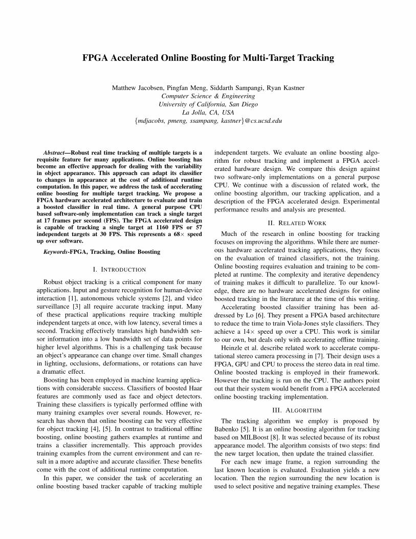
Figure 1: Circular search region with radius s (left). Circular region withradius r for positive examples and sampled annular region with radii q andq′ for negative examples (right).
training set to all the samples in a tight radius, r, around thenewly found object location. The negative training set is asparse sampling from an annular region between two radii, qand q′, surrounding the newly found location. See Figure 1for an illustration of these regions.
The algorithm uses Haar-like features, similar to thoseused for face and object detection [10]. At initialization,a pool of M Haar features are generated with randomrectangle coordinates and weights. During training, K ofthese features are selected and are used as weak classifiers,h(x), to form the strong classifier, H(x) =
∑k hk(x).
Each weak classifier consists of a Haar feature and fouradditional parameters. These additional parameters quantifythe degree to which the feature represents the object beingtracked. They are updated during training using positive andnegative samples. At runtime, each weak classifier predictsthe likelihood of a sample window using the log oddsratio between positive and negative examples. This formularesults in higher scores the closer a sample’s feature valueis to the mean of the positive examples.
IV. FPGA DESIGN
Our design is motivated by a human computer interactionapplication. The application requirements are to track at leastthree independent points at 30 frames per second (FPS). Itmust also evaluate frames at three different scales to trackobjects as they move closer and further from the camera.
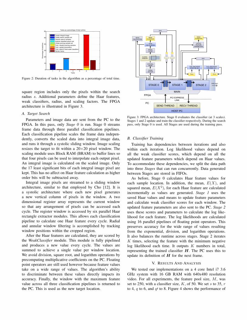
The algorithm was initially implemented in software andprofiled. Our FPGA design accelerates the slowest tasks,identified in Figure 2. The largest amount of time (54.5%)is spent training the classifier. Boosting is inherently se-quential. Each training iteration must wait for the previousiteration to complete before starting the next.
The FPGA design is partitioned between software andhardware. The software is responsible for acquiring imageframes, passing data to the FPGA, receiving data from theFPGA, and keeping track of state. The algorithm initializesin software. Targets of any size can be tracked, but theyare scaled to fit a fixed hardware window size of 20×20.CPU-FPGA communication is achieved using RIFFA [11].
For each new 8 bit grayscale image frame, a squareregion of the frame surrounding the current location iscropped and sent to the FPGA along with parameters. The
1 2 3 4 5 6 70
10
20
30
40
50
60
Tasks
Perc
enta
ge o
f tot
al ti
me
Tasks as a percentage of total runtime
Create integral imageCreate search sample setClassify search samplesArgmax classified search set Create pos/neg sample setTrain: classify pos/neg samplesTrain: update parametersTrain: select K best weak classifiersRender frame
Figure 2: Duration of tasks in the algorithm as a percentage of total time.
square region includes only the pixels within the searchradius s. Additional parameters define the Haar features,weak classifiers, radius, and scaling factors. The FPGAarchitecture is illustrated in Figure 3.
A. Target Search
Parameters and image data are sent from the PC to theFPGA. In this pass, only Stage 0 is run. Stage 0 streamsframe data through three parallel classification pipelines.Each classification pipeline scales the frame data indepen-dently, converts the scaled data into integral image data,and runs it through a systolic sliding window. Image scalingresizes the target to fit within a 20×20 pixel window. Thescaling module uses Block RAM (BRAM) to buffer lines sothat four pixels can be used to interpolate each output pixel.An integral image is calculated on the scaled image. Onlythe 17 least significant bits of each integral image pixel arekept. This has no affect on Haar feature calculation as higherorder bits will be subtracted away.
Integral image pixels are streamed to a sliding windowarchitecture, similar to that employed by Cho [12]. It isa systolic architecture where each new pixel generatesa new vertical column of pixels in the window. A twodimensional register array represents the current windowso that any arrangement of pixels can be accessed eachcycle. The register window is accessed by six parallel Haarrectangle extractor modules. This allows each classificationpipeline to calculate one Haar feature every cycle. Radialand annular window filtering is accomplished by trackingwindow positions within the cropped region.
After the Haar features are calculated, they are scored bythe WeakClassifier module. This module is fully pipelinedand produces a new value every cycle. The values aresummed to achieve a single value per window location.We avoid division, square root, and logarithm operations byprecomputing multiplicative coefficients on the PC. Floatingpoint operators are still used however because feature valuestake on a wide range of values. The algorithm’s abilityto discriminate between these values directly impacts itsaccuracy. Finally, the window with the maximum featurevalue across all three classification pipelines is returned tothe PC. This is used as the new target location.
MEAN CALCULATION
UPDATE FEATURE
PARAMETERS
WEAK CLASSIFIER
HOST PC
RECV THREAD SEND THREAD
STAGE 0
MAIN
PCI EXPRESS LINK
FPGA
PC
STAGE 1 STAGE 2 PIPELINED
HPOS
MAX
LOG LIKELIHOOD (FOR POS. EX.)
HNEG
LOG LIKELIHOOD (FOR NEG. EX.)
FRAME SCALER
INTEGRAL IMAGE
RADIAL FILTER
HAAR CALCULATION
SLIDING WINDOW
MAX
WEAK CLASSIFIER
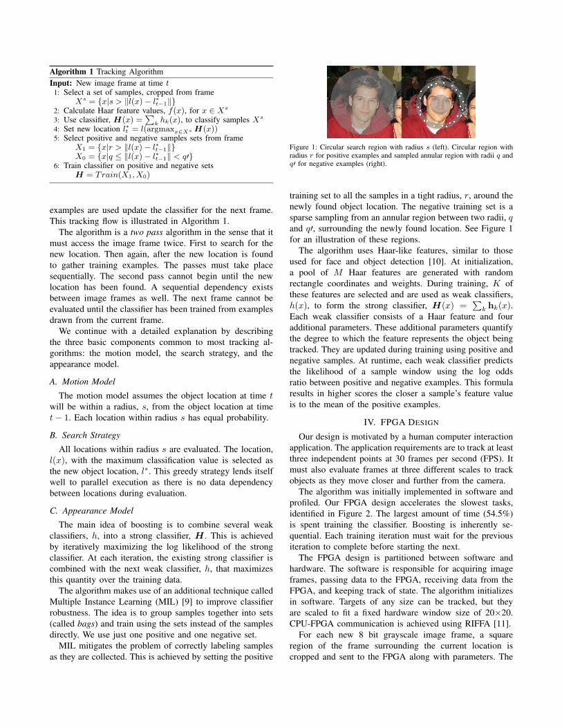
Figure 3: FPGA architecture. Stage 0 evaluates the classifier (at 3 scales).Stages 1 and 2 update and train the classifier respectively. During the searchpass, only Stage 0 is used. All Stages are used during the training pass.
B. Classifier Training
Training has dependencies between iterations and alsowithin each iteration. Log likelihood values depend onall the weak classifier scores, which depend on all theupdated feature parameters which depend on Haar values.To accommodate these dependencies, we split the data pathinto three Stages that can run concurrently. Data generatedbetween Stages are stored in FIFOs.
As before, Stage 0 calculates Haar feature values foreach sample location. In addition, the mean, E(X), andsquared mean, E(X2), for each Haar feature are calculatedincrementally as values are generated. Stage 1 uses thesaved Haar values and means to update feature parametersand calculate weak classifier scores for each window. Theupdated feature parameters are also sent to the PC. Stage 2uses these scores and parameters to calculate the log like-lihood for each feature. The log likelihoods are calculatedusing 16 parallel pipelines of floating point operators. Thispreserves accuracy for the wide range of values resultingfrom the exponential, division, and logarithm operations.It also balances the runtime across stages. Stage 2 iteratesK times, selecting the feature with the minimum negativelog likelihood each time. It outputs K numbers in total,representing the trained classifier H . The PC uses this toupdate its definition of H for the next frame.
V. RESULTS AND ANALYSIS
We tested our implementations on a 4 core Intel i7 3.6GHz system with 16 GB RAM with 640x480 resolutionvideo. For all experiments, the feature pool size, M , wasset to 250, with a classifier size, K, of 50. We set s to 35, rto 4, q to 6, and q′ to 8. Figure 4 shows the performance of
1 10 100 1,000
MATLAB
C++
FPGA
Frames per second
Impl
emen
tatio
nsImplementation performance
3 locations1 location1x
68x68x
0.007x
1x
17
Figure 4: Performance of implementations (longer is better). Speed up overC++ software is shown to right of each bar.
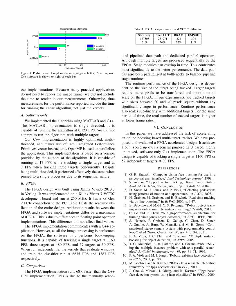
our implementations. Because many practical applicationsdo not need to render the image frame, we did not includethe time to render in our measurements. Otherwise, timemeasurements for the performance reported include the timefor running the entire algorithm, not just the kernels.
A. Software-only
We implemented the algorithm using MATLAB and C++.The MATLAB implementation is single threaded. It iscapable of running the algorithm at 0.123 FPS. We did notattempt to run the algorithm with multiple targets.
Our C++ implementation is highly optimized, multi-threaded, and makes use of Intel Integrated PerformancePrimitives vector instructions. OpenMP is used to parallelizethe application. This implementation is based on a versionprovided by the authors of the algorithm. It is capable ofrunning at 17 FPS while tracking a single target and at7 FPS when tracking three targets concurrently. Despitebeing multi-threaded, it performed effectively the same whenpinned to a single processor due to its sequential nature.
B. FPGA
The FPGA design was built using Xilinx Vivado 2013.3in Verilog. It was implemented on a Xilinx Virtex 7 VC707development board and run at 250 MHz. It has a x8 Gen2 PCIe connection to the PC. Table I lists the resource uti-lization of the entire design. Arithmetic results between theFPGA and software implementations differ by a maximumof 0.77%. This is due to differences in floating point operatorimplementations. This difference did not affect final values.
The FPGA implementation communicates with a C++ ap-plication. However, as all the image processing is performedon the FPGA, the software only performs bookkeepingfunctions. It is capable of tracking a single target at 1160FPS, three targets at 480 FPS, and 57 targets at 30 FPS.When run independently, the kernels that evaluate windowsand train the classifier run at 6635 FPS and 1383 FPSrespectively.
C. Comparison
The FPGA implementation runs 68× faster than the C++CPU implementation. This is due to the manually sched-
Table I: FPGA design resource and VC707 utilization.
Slice Reg. Slice LUT BRAM DSP48E187505 231971 224 304
31% 76% 22% 11%
uled pipelined data path and dedicated parallel operators.Although multiple targets are processed sequentially by theFPGA, Stage modules can overlap in time. This contributesmost significantly to the better performance. The data pathhas also been parallelized at bottlenecks to balance pipelinestage runtimes.
The runtime performance of the FPGA design is depen-dent on the size of the target being tracked. Larger targetsrequire more pixels to be transferred and more time toscale on the FPGA. In our experiments, we tracked targetswith sizes between 20 and 40 pixels square without anysignificant change in performance. Runtime performancealso scales sub-linearly with additional targets. For the sameperiod of time, the total number of tracked targets is higherat lower frame rates.
VI. CONCLUSION
In this paper, we have addressed the task of acceleratingan online boosting based multi-target tracker. We have pro-posed and evaluated a FPGA accelerated design. It achievesa 68× speed up over a general purpose CPU based, highlyoptimized, software-only C++ implementation. The FPGAdesign is capable of tracking a single target at 1160 FPS or57 independent targets at 30 FPS.
REFERENCES
[1] G. R. Bradski, “Computer vision face tracking for use in aperceptual user interface,” Intel Technology Journal, 1998.
[2] S. Avidan, “Support vector tracking,” IEEE Trans. PatternAnal. Mach. Intell, vol. 26, no. 8, pp. 1064–1072, 2004.
[3] D. Snow, M. J. Jones, and P. Viola, “Detecting pedestriansusing patterns of motion and appearance,” in ICCV, 2003.
[4] H. Grabner, M. Grabner, and H. Bischof, “Real-time trackingvia on-line boosting,” in BMVC, 2006, p. I:47.
[5] B. Babenko and M.-H. Y. S. Belongie, “Robust object track-ing with online multiple instance learning,” TPAMI, 2011.
[6] C. Lo and P. Chow, “A high-performance architecture fortraining viola-jones object detectors,” in FPT. IEEE, 2012.
[7] S. Heinzle, P. Greisen, D. Gallup, C. Chen, D. Saner,A. Smolic, A. Burg, W. Matusik, and M. H. Gross, “Com-putational stereo camera system with programmable controlloop,” ACM Trans. Graph, vol. 30, no. 4, p. 94, 2011.
[8] P. A. Viola, J. C. Platt, and C. Zhang, “Multiple instanceboosting for object detection,” in NIPS, 2005.
[9] T. G. Dietterich, R. H. Lathrop, and T. Lozano-Perez, “Solv-ing the multiple instance problem with axis-parallel rectan-gles,” Artificial Intelligence, vol. 89, pp. 31–71, 1997.
[10] P. A. Viola and M. J. Jones, “Robust real-time face detection,”in ICCV, 2001, p. 747.
[11] M. Jacobsen and R. Kastner, “Riffa 2.0: A reusable integrationframework for fpga accelerators,” in FPL, 2013.
[12] J. Cho, S. Mirzaei, J. Oberg, and R. Kastner, “Fpga-basedface detection system using haar classifiers,” in FPGA, 2009.