Embed Size (px)
Citation preview

FPGA-BASED RECTIFICATION AND LENS UNDISTORTION FOR AREAL-TIME EMBEDDED STEREO VISION SENSOR
Emanuel Staudinger, Martin Humenberger and Wilfried Kubinger
Austrian Research Centers GmbH - ARCDonau-City-Str. 1, 1220 Vienna, Austria
phone: +43-50550-4139, fax: +43-50550-4250, email: [email protected]: www.smart-systems.at
1. ABSTRACT
This paper presents the implementation of a Lens Distortion and Rectification Unit (LDRU). The unit is well suitedfor lens undistortion and for stereo head rectification in embedded real-time systems. The proposed architecturehas been realized on a prototyping system based on an Altera STRATIX EP1S60 FPGA resulting in a performanceof 35 frames per second for a 1024× 1024 pixels input image.
2. INDRODUCTION
Modern applications such as robot assembling automation, upcoming mobile robot platforms for homes, and carsafety features require both, 3D perception and object classification, for navigation and object manipulation [9].Real-time performance of approximately 30 frames per second is mandatory and a very critical design issue. Em-bedded stereo vision sensors, consisting of a sensor head and a calculation unit, are very well suited for stereoscopicperception but require huge computational effort. Due to mounting tolerances within the sensor head, resulting ina maximum relative shift and revolution of these two camera images, rectification is absolutely necessary to reducethe matching effort. In our employed method it is done by applying a remap with offline calculated coefficients.The camera lenses also have an impact on the source image, resulting in a distortion in border areas which isreversed by a second remap. By undistorting and rectifying the original camera images, the computational effortfor subsequent tasks like stereo matching is dramatically reduced, thus setting a very important step to achievereal-time performance.
Approaches implementing lens undistortion and rectification on DSP based platforms or general purpose CPUbased platforms are very often insufficient [6]. Considering reduced power usage and small form factors, generalpurpose CPUs (even with multimedia extensions) are outperformed by Digital Signal Processors (DSPs) and theirmassive parallel architecture [4]. Also the DSP’s resource usage, including computation and memory transfersfor this correction process, is far too high and nearly leaves no evaluation time for high level applications. Highmemory bandwidths, low memory latencies, and the overall resource consumption inhibit the usage of DSPs forthis application [2].
The presented solution to overcome this bottleneck is a dedicated hardware implementation, bypassing thedisadvantages of common platforms. Current Field Programmable Gate Array (FPGA) systems deliver enoughresources and performance, by reduced form factors to fulfill all necessary requirements [7],[10]. Their tightlycoupled memory architecture, and their possibility to flatten designs qualifies them for image processing [11].Therefore, a generic IP-Core with a simple input/output image interface, a parameter cache interface for thecombined undistortion and rectification coefficients and minimized FPGA utilization is designed and tested on anexisting platform. By keeping this core generic, it offers a nearly seamless integration and reusability for futureprojects, too.
This paper is organized as follows: Section 3 shortly briefs on the basics and necessities of rectification andundistortion. Sections 4 and 5 present the proposed architecture, describe the target oriented implementationand synthesis results. The conclusion is supplemented with techniques for eliminating the cache architecture byon-the-fly calculation of the remap coefficients.
1
3. BASICS OF RECTIFICATION AND LENS-UNDISTORTION
In our approach, the preceding action before rectification and lens-undistortion requires a few steps: At first rawimages from the sensor head are grabbed by a conventional computer based software framework which controls thecameras. The resulting specific parameters are combined in three camera matrices, shown in equ. 1, and are calledCamera Matrix, Distortion Coefficents, and Rectification Matrix. The first two matrices are used for undistortionand the third one obviously for rectification [8].
CameraMatrix :
[fx 0 cx
0 fy cy
0 0 1
]DistortionCoefficentsMatrix : [d1 d2 d3 d4]
RectificationMatrix :
[a1 a2 a3
a4 a5 a6
a7 a8 a9
] (1)
The combined offset parameters needed for our image remap method are calculated from these matrices. Eq. 2shows the offset calculation using the first two matrices and eq. 3 the perspective warping for rectification. Theseoffsets for a certain coordinate pair (Xi|Yj) are simply added and represent the combined remap offset for the(Xi|Yj) target image pixel.[
xn
yn
]=
[Xi−cx
fxYj−cy
fy
][xd
yd
]=(1 + d1r
2 + d2r4) [xn
yn
]+[d3 (2xnyn) + d4
(r2 + 2x2
n
)d3
(r2 + 2y2
n
)+ d4 (2xnyn)
]r =
√x2
n + y2n[
ud
vd
]=[fxxd + cx
fyyd + cy
]
OffsetUndistortX = ud −Xi
OffsetUndistortY = vd − Yj
(2)
[ur
vr
]=
[a1Xi+a2Yj+a3a7Xi+a8Yj+a9a4Xi+a5Yj+a6a7Xi+a8Yj+a9
]
OffsetRectifyX = ur −Xi
OffsetRectifyY = vr − Yj
OffsetX = OffsetUndistortX + OffsetRectifyX
OffsetY = OffsetUndistortY + OffsetRectifyY
(3)
The process of grabbing various images and calculating the specific matrices is not further described in this paperbecause this functionality is basically state of the art software and available through e.g. the Open Source ComputerVision Library, OpenCV [3].
Fig. 1 shows the left and right raw images from a stereo head and also demonstrates the used verification patternfor the camera specifc matrices determination. The afterwards added white bar gives a good view why rectifica-tion is absolutely essential for subsequent stereo matching. In these presented images, the horizontal deviation isapproximately 23 pixels thus increasing the search space for stereo matching from one image line to more than 23lines. A slight lens distortion can be seen at the right image boundary at the door, resulting in a bent door frameand can be reduced in advance by deployment of higher quality lenses and a more accurate objective cavity withinthe camera housing. The rectified and undistorted image for the stereo-head’s right camera is shown in fig. 2. Theremapping process rotated the image and the perspective plane and also reduces the valid image region. This imagealso shows the sensor chip mounting tolerances between two actually identical cameras.
2

Figure 1: Raw stereo pair images with supplementary white bar for visualization.
Figure 2: Rectified and undistorted right camera image.
Implementing floating point based rectification and undistortion algorithms on a FPGA-based embedded systemposes the question of the required fixed point format which directly influences the FPGA’s resource utilization,external memory usage, and memory transfer bandwidth. The integer component is defined by the max. allowabledeviation within an image and a range of e.g. −128 to +127 is more than sufficient for the offset values ([−64, +63] inour implementation). The fractional part is determined by the required subpixel accuracy of subsequent processingblocks and the sensor chip itself. An empirical value is approximately 10 per cent of the offset value. Theserequirements lead to an easy to handle 8.8 fixed point format in our implementation, requiring 2 bytes for oneparameter and 4 bytes for a (Xi|Yj) parameter pair.
The basic computation flow for remapping, neglecting boundary checks, whether FPGA based or processorbased is as follows:1. Create target coordinates (Xi|Yj) and look up the related offset parameter pair in a table.
2. Add the offset to the target coordinates to acquire the actual source image coordinates(X
′
i |Y′
j
), take these four
adjacent pixel values instead of the values at (Xi|Yj) and interpolate.
1 2
3 4
(Xi’|Yj’)
X
Y
3. Increment target coordinates and loop back to step 1.
3
4. SYSTEM-ARCHITECTURE
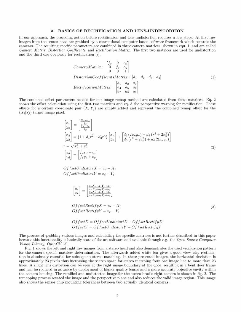
A widely used FPGA-based architecture for image acquisition and image preprocessing of a stereo camera systemis shown in fig. 3. The cameras are connected to the FPGA using either Ethernet, Firewire, CameraLink or aproprietary interface, and are triggered by e.g. the FPGA or externally. The camera trigger pulses should besynchronized or even be the same to minimize the relative transfer delay between the two images thus reducingthe overall effort for buffering and image synchronization within the signal processing blocks. The images arethen processed by the rectification and undistortion units (hence called LDRU). Afterwards they are processed byoptional subsequent blocks like e.g. stereo matching and transferred through an output interface to a conventionalcomputer or, most commonly used, a DSP postprocessing system. The camera MACs are used to adapt differentcamera interfaces to our internally defined image processing interface and offload all nonrelevant, camera specific,controls and data protocols. The output MAC either directly takes streamed data from a signal processing block oraccesses the external memory to transfer the final images to a postprocessing system using miscellaneous interfacesand protocols, like DSP memory interfaces, Rapid-IO for example [1]. The LDRUs load the required combined offset
Camera-MAC
Trigger
LDRUleft
Output-MAC
ImageProcessing Algorithms
Memory Arbitration
Optional Units and Buses
Image Datapath
Memory Buses
DSP / PC ..
FPGA
Softcore
Camera-MAC LDRUright
L
R
Stereo -Sensorhead
Figure 3: Common high level architecture for FPGA-based image processing.
parameters from an external memory using a global memory arbitration unit which handles all external memoryaccesses for all signal processing blocks. In most systems a softcore or FPGA-internal, hardwired processor core isused to initialize the system and cameras, to ensure proper error handling and to generate the offset parameters.The underlying hardware design, used in this paper for testing the LDRU, uses an Altera NIOS II/f softcoreoperating at 100 MHz to calculate the parameters for both cameras during the boot phase and stores them in anexternal DDR-RAM memory bank. The advantage of this system architecture is its simplicity to replace or addsignal processing blocks and to add external memory accesses as long as the overall memory transfer bandwidth isnot exceeded. The main disadvantage is the necessity of a relatively large external memory for storing the offsetparameters and the transfer bandwidth used by the LDRUs to load them. Assuming a 40 MHz pixel clock (withoutany delay between lines and frames), a 1024× 1024 image and a 8.8 fixed point format for one parameter (X or Ydirection of one camera) we get an overall memory usage of
2 cameras · 2 Bytes · 2 · 1024 · 1024 = 8 MBytes (4)
4
and a peak memory transfer bandwidth of
2 cameras · 2 Bytes · 2 · 40 MHz = 320MBytes
s(5)
Considering additional concurrent memory accesses e.g. stereo matching and output transfer of a depth image,the overall bandwidth reaches 400 MBytes
s and more which can currently easily achieved by banked DDR-RAMmemory. The image interface from and to the LDRUs is very simple and expandable, with strobes in the forwardpath signaling the validation of data, lines, and frames and a busy signal in the backward path for stalling the datatransfer.
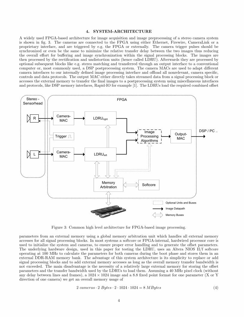
Fig. 4 shows the high level design of one LDRU with the design specific blocks and the external memoryinterconnection. The interpolation unit gets four adjacent source pixels and calculates the final destination pixel
Camera-MAC Even & Odd
lines splitter
Image RAM- 64 Even lines- 1024 Pixel per line- Ring buffer
Control
Image RAM- 64 Odd lines- 1024 Pixel per line- Ring buffer
Control
Address Generation & Flow Control
x
y
DestinationImage
(Xi|Yj)
Interpolation LDRU Output
8 bit
8 bit
Parameter Cache- 512 Parameters
ControlMemory
Arbitration
2nd LDRU
0.8
Fixe
d P
oint
Offs
et (x
|y)
(Xi|Y
j)
Rea
d &
Writ
e A
ddr.
Optional Buses
Image Datapath
Memory Buses
Addresses & Internal Data
2x 8 bit
2x 8 bit
LDRU
(Xi’|Y
j’)
Figure 4: Lens Undistortion and Rectification Unit – Architecture for one camera.
value by linear interpolation using the fractional part out of the 8.8 fixed point X/Y offset. Inevitable multiplicationsin this mathematical operation require a fully pipelined interpolation unit design to achieve a required 133 MHzoperating clock for the underlying hardware and leads to an insignificant latency of seven system clocks. Theparameter cache is a dual ported memory capable of storing parameters for 512 pixels and is divided in two banks to256 parameter pairs each. This cache calculates the source coordinates
(X
′
i , Y′
j
)out of the given target coordinates
(Xi, Yj) by adding the offsets and uses a simple caching scheme to update the paramters from the external memory.Therefore one cache-bank is read only for coordinate computation and the other bank is concurrently filled withnew parameters. Storing and synchronizing the incoming pixels from the camera requires a certain amount of bufferwhich is realized as cyclic buffer by the image RAMs. Due to the nature of this design and performance issues, animage is splitted into even and odd lines to simplify the address generation and to reduce multiple memory accessesfor four adjacent pixels. This unit also includes an implicit control path to directly generate a second read strobefor accessing the next higher pixel. The last design unit contains the address generation and flow control for theLDRU and includes additional tasks like error handling of truncated images and strobe generation for the LDRUoutput interface. To simplify the overall design and to minimze the impact on the FPGA’s resources, this unit is
5
implemented as a three cycle, partially pipelined finite state machine thus reducing the max. processible pixel clockto a third of the system clock ( 133MHz
3 ≈ 44Mhz). The main task of this unit is to calculate the destination imagebackward from the incoming source image and the sequence is as follows:1. Wait until 64 lines are stored in image RAMs.2. Create destination image coordinates and access parameter cache.3. Read adjusted coordinates from parameter cache, validate image boundaries and access image RAMs to acquire
the correct pixels.4. Create strobes for output interface and transfer source image pixels to interpolation unit.5. Loop back to the first step.As described earlier, the parameters are generated by a softcore during the startup phase and requires approximatelythree minutes for computing all parameters if no further software optimization is used. This duration is acceptablefor laboratory tests but unthinkable for a sensor head mounted on a mobile robot with fast startup times. Excessivenumeric optimizations and the usage of floating point hardware accelerators lead to an overall computation time ofappr. 2.3 seconds for the boot process and could be further reduced by specialized hardware as proposed in section6.
5. RESULTS
The underlying hardware design used in this paper for functional validation uses two CameraLink high dynamicrange cameras and an Altera mid-end FPGA. The resulting images from the LDRU are identical to images producedin Matlab or on a PC C-code environment using quantized offset parameters. Margin values are not furtherconsidered because subsequent signal processing blocks limit the image dimensions by defining their own regions ofinterest. Poorly mounted sensor chips and lenses lead to limited active regions within a rectified and undistortedimage, too.
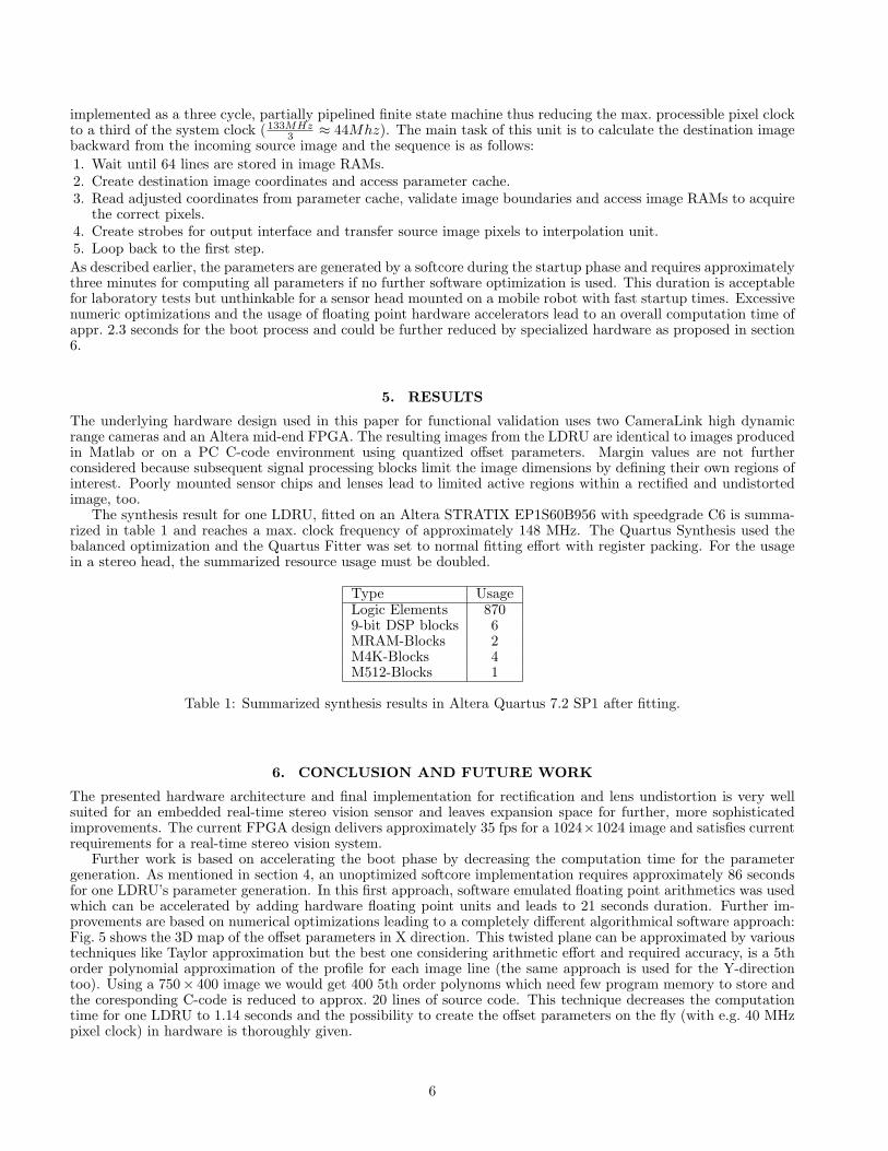
The synthesis result for one LDRU, fitted on an Altera STRATIX EP1S60B956 with speedgrade C6 is summa-rized in table 1 and reaches a max. clock frequency of approximately 148 MHz. The Quartus Synthesis used thebalanced optimization and the Quartus Fitter was set to normal fitting effort with register packing. For the usagein a stereo head, the summarized resource usage must be doubled.
Type UsageLogic Elements 8709-bit DSP blocks 6MRAM-Blocks 2M4K-Blocks 4M512-Blocks 1
Table 1: Summarized synthesis results in Altera Quartus 7.2 SP1 after fitting.
6. CONCLUSION AND FUTURE WORK
The presented hardware architecture and final implementation for rectification and lens undistortion is very wellsuited for an embedded real-time stereo vision sensor and leaves expansion space for further, more sophisticatedimprovements. The current FPGA design delivers approximately 35 fps for a 1024×1024 image and satisfies currentrequirements for a real-time stereo vision system.
Further work is based on accelerating the boot phase by decreasing the computation time for the parametergeneration. As mentioned in section 4, an unoptimized softcore implementation requires approximately 86 secondsfor one LDRU’s parameter generation. In this first approach, software emulated floating point arithmetics was usedwhich can be accelerated by adding hardware floating point units and leads to 21 seconds duration. Further im-provements are based on numerical optimizations leading to a completely different algorithmical software approach:Fig. 5 shows the 3D map of the offset parameters in X direction. This twisted plane can be approximated by varioustechniques like Taylor approximation but the best one considering arithmetic effort and required accuracy, is a 5thorder polynomial approximation of the profile for each image line (the same approach is used for the Y-directiontoo). Using a 750× 400 image we would get 400 5th order polynoms which need few program memory to store andthe coresponding C-code is reduced to approx. 20 lines of source code. This technique decreases the computationtime for one LDRU to 1.14 seconds and the possibility to create the offset parameters on the fly (with e.g. 40 MHzpixel clock) in hardware is thoroughly given.
6
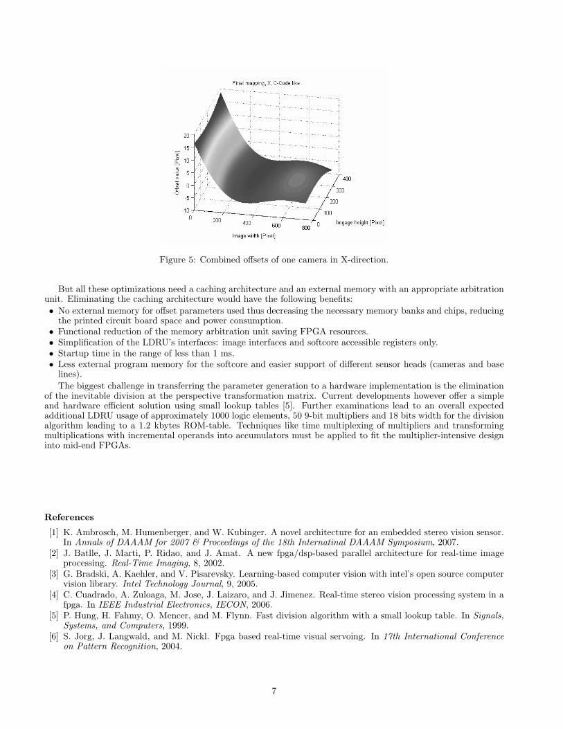
Figure 5: Combined offsets of one camera in X-direction.
But all these optimizations need a caching architecture and an external memory with an appropriate arbitrationunit. Eliminating the caching architecture would have the following benefits:• No external memory for offset parameters used thus decreasing the necessary memory banks and chips, reducing
the printed circuit board space and power consumption.• Functional reduction of the memory arbitration unit saving FPGA resources.• Simplification of the LDRU’s interfaces: image interfaces and softcore accessible registers only.• Startup time in the range of less than 1 ms.• Less external program memory for the softcore and easier support of different sensor heads (cameras and base
lines).The biggest challenge in transferring the parameter generation to a hardware implementation is the elimination
of the inevitable division at the perspective transformation matrix. Current developments however offer a simpleand hardware efficient solution using small lookup tables [5]. Further examinations lead to an overall expectedadditional LDRU usage of approximately 1000 logic elements, 50 9-bit multipliers and 18 bits width for the divisionalgorithm leading to a 1.2 kbytes ROM-table. Techniques like time multiplexing of multipliers and transformingmultiplications with incremental operands into accumulators must be applied to fit the multiplier-intensive designinto mid-end FPGAs.
References
[1] K. Ambrosch, M. Humenberger, and W. Kubinger. A novel architecture for an embedded stereo vision sensor.In Annals of DAAAM for 2007 & Proceedings of the 18th Internatinal DAAAM Symposium, 2007.
[2] J. Batlle, J. Marti, P. Ridao, and J. Amat. A new fpga/dsp-based parallel architecture for real-time imageprocessing. Real-Time Imaging, 8, 2002.
[3] G. Bradski, A. Kaehler, and V. Pisarevsky. Learning-based computer vision with intel’s open source computervision library. Intel Technology Journal, 9, 2005.
[4] C. Cuadrado, A. Zuloaga, M. Jose, J. Laizaro, and J. Jimenez. Real-time stereo vision processing system in afpga. In IEEE Industrial Electronics, IECON, 2006.
[5] P. Hung, H. Fahmy, O. Mencer, and M. Flynn. Fast division algorithm with a small lookup table. In Signals,Systems, and Computers, 1999.
[6] S. Jorg, J. Langwald, and M. Nickl. Fpga based real-time visual servoing. In 17th International Conferenceon Pattern Recognition, 2004.
7

[7] Y. Kukimoto and M. Fujita. Rectification method for lookup-table type fpga’s. In ICCAD ’92: 1992IEEE/ACM international conference proceedings on Computer-aided design, pages 54–61. IEEE ComputerSociety Press, 1992.
[8] J. Mallon and P. Whelan. Projective rectification from the fundamental matrix. Image and Vision Computing,23, 2005.
[9] D. Murray and J. Little. Using real-time stereo vision for mobile robot navigation. Autonomous Robots,8(2):161–171, 2000.
[10] F. Rinnerthaler, W. Kubinger, J. Langer, M. Humenberger, and S. Borbely. Boosting the performance ofembedded vision systems using a dsp/fpga co-processor system. Systems, Man and Cybernetics, 7, 2007.
[11] C. Vancea and S. Nedevschi. Lut-based image rectification module implemented in fpga. In Intelligent ComputerCommunication and Processing, 2007.
8