Embed Size (px)
Citation preview

The demanding requirements put forth by redundant operation for both payload and management power
can be met and interoperability between the power modules and the MicroTCA carrier hub achieved using MicroTCA compliant products.
RedundantMicroTCAPower Systems
Technical Paper 012First Presented at the MicroTCA conference 2008
REDUNDANT MICROTCA POWER SYSTEMS 2
ABOUT THIS PAPERThe material contained in this paper was first presented on June 3rd, 2008 at the MicroTCA conference.
This focused one-day international conference served an audience of decision makers who are interested in learning about and contributing to the latest practical advancements related to the use of MicroTCA systems and components. The conference targeted hardware & software designers, engineering managers, system integrators and product managers.
1. INTRODUCTION
The Micro Telecommunications Computing Architecture (MicroTCA™) platform is becoming increasingly popular as a packaging solution for small to intermediate sized Information and Communications Technology (ICT) equipment. It offers several benefits for these types of systems, including high performance, design flexibility, high availability configurations and cost effectiveness. The MicroTCA specification defines requirements for the power system components, including the MicroTCA power module (PM), which contains the majority of the power generation and control functionality for the system. The specification contains stringent requirements for the power module when redundant power modules are utilized to achieve high availability system operation. This paper will present the results of a case study on using standard Flex PMs in a redundant configuration.
An overview of the MicroTCA power architecture will be provided along with a summary of the PM design requirements as they relate to redundant operation. This will be followed by a description of how these requirements are implemented with Flex’s PM design. Finally, results of performance verification testing will be provided that demonstrate how the Flex design meets the demanding requirements of redundant operation for both payload and management power, including loss of input power, PM failure and hotswapping. The testing will also demonstrate that interoperability is achieved between the PMs and the MicroTCA Carrier Hubs (MCH) during the interval of handing over system power responsibility from one PM to another.
This paper is intended for a wide audience including MicroTCA OEM system integrators, engineers involved with selecting, evaluating and testing of PMs, and manufacturers of MCHs. The results provided should enhance the confidence level that these designs can indeed meet the stringent requirements of 1+1 redundancy, including transitioning through a power failure without interruption of system payload and management power. Increased credibility in the overall MicroTCA platform concept should also be achieved, in terms of demonstrating interoperability between different components and suppliers. It will be shown that standard MicroTCA components that are in compliance with the specification can achieve all of the difficult objectives associated with redundancy without the need to resort to expensive and risky customized solutions.
CONTENTS
1.0 INTRODUCTION 2
2.0 MICROTCA POWER REQUIREMENTS OVERVIEW 3
3.0 FLEX POWER MODULE IMPLEMENTATION 6
3.1 CHANNEL POWER CONTROL 6
3.2 DC/DC CONVERTER 7
4.0 PERFORMANCE VERIFICATION 8
4.1 LOSS OF INPUT VOLTAGE OR
POWER MODULE FAILURE 8
4.2 HOTSWAP 11
5.0 SUMMARY AND CONCLUSIONS 12
7.0 GLOSSARY 13
8.0 REFERENCES 13
REDUNDANT MICROTCA POWER SYSTEMS 3
2. MICROTCA POWER REQUIREMENTS OVERVIEW
This section is intended to provide a brief summary of the requirements for a MicroTCA power system, with a focus on the PM specifications as they relate to redundant operation. The information included is from the MTCA.0 R1.0 version of the MicroTCA specification [1]. Additional information about the power implementation of the MicroTCA platform can be found in reference [3]. This paper only addresses redundancy as it applies to payload and management power. Some high availability MicroTCA systems may also extend redundancy into the AC/DC front-ends and input power distribution, but these techniques are outside the scope of this discussion.
2. MICROTCA POWER REQUIREMENTS OVERVIEW
The MicroTCA platform requires all payload circuitry to reside in AdvancedMC™ (AMC) modules and centralizes all the main power conversion/control functions for a sub-rack into one or more PMs. The overall architecture of a MicroTCA system is shown in Figure 1. The system as shown in the figure supports up to a maximum of 12 AMC modules which contain the payload circuitry, and each of these AMCs is specified to require from 20 to 80 watts of payload power. The MCH function provides overall control for the interconnected AMCs. A second redundant MCH is often added for systems with high availability requirements. Similarly, a second redundant cooling unit (CU) is sometimes used. The backplane is used as an interconnection mechanism for all of these elements.
Cooling Unit #2
AMC#1
AMC#3
AMC#2
AMC#7
AMC#9
AMC#8
AMC
#12
AMC
#10
AMC#6
AMC#5
AMC#4
AMC
#11
AirMover
Cooling Unit #1
EMMC
Micro TCA CarrierMicro TCA Carrier Hub (MCH) #2
Micro TCA Carrier Hub (MCH) #1
MCMC
CommonOptionsFabric
ClockFat PipeFabric
JSM
Power Module #2
EMMCPower Control
PayloadPower
Converter
Magm’tPower
Converter
Power Module #1
Power Module #N
Backplane Interconnect
InputSource
Figure 1 - MicroTCA block diagram with parts of the power system highlighted
REDUNDANT MICROTCA POWER SYSTEMS 4
The power module is a very key element in the overall MicroTCA system. It serves as a centralized power conditioning, conversion and control block for the entire sub-rack. Anywhere from one to four power modules may be used in a single MicroTCA system with more than one being used either because of the power demand or because of a desire for redundancy. The PM provides payload power at a nominal 12 V level and management power at a nominal 3.3 V. In addition to supplying payload and management power to up to 12 AMCs, the PMs must be capable of supplying payload and management power to up to two CUs and two MCHs. As a consequence, many PMs are designed to provide a total of 16 output power channels, or 32 channels if payload and management power are considered separately. A block diagram of a typical PM is shown in Figure 2. A photograph of the Flex PM used in this case study is provided in Figure 3 together with a summary of its specifications. Additional detail regarding the overall design and functionality of the PM can be found in reference [2].
The MicroTCA specification includes provision for redundant PMs to increase system availability in critical applications. The specification contains very specific requirements for the implementation of power module redundancy. Techniques such as power paralleling and current sharing are not used, and only one power module may deliver current to any load channel at any given time. This architectural restriction was established so that the maximum overcurrent possible to any channel is limited. If two power modules were paralleled, the maximum fault current could be doubled, which would expose the system backplane and connectors to excessive current and possibility of damage.
MicroTCA PMs are defined as either “primary” or “redundant”. One or more primary PMs supply the payload and management power under normal system operating conditions. Each system can contain one redundant PM that takes over for a failed primary PM.
-48 V Hold-upEMI-filter DC/DC
Converter48 V ->12 V
Hot-swap12 V (16x)
12 VPayload Power16 Outputs
RTN
POL 3A12 V ->3.3 V
Hot-swap3.3 V (16x)
3.3 VManagement Power16 OutputsEnhanced Module
Management Controller(EMMC)
IPMB
Figure 2 - Example of MicroTCA power module block diagram
OUTPUT POWER 355 W
INPUT POWER 385 W
OUTPUT VOLTAGE CHANNELS 16 X 12 V AND 16 X 3.3 V
EFFICIENCY AT 50% LOAD 95%
NORMAL INPUT VOLTAGE (FULL PERFORMANCE) -40.5 V TO -57 V
HOLD-UP (-54 V IN) 8 MS
CONDUCTED EMISSIONS CLASS B
FORM FACTOR FULL SIZE (6HP) SINGLE-WIDTH
REDUNDANT MICROTCA POWER SYSTEMS 5
After this transition is complete, the former redundant PM then acts as the primary PM for the assigned loads. It is important to understand that any given PM is either primary or redundant at any given time. It cannot simultaneously provide both roles. The specification requirements can be summarized as follows:
• ONE PM IS ASSIGNED TO BE REDUNDANT. ALL OTHER PMS ARE PRIMARY.
• THE MCH CANNOT ASSIGN ANY CHANNELS ON THE REDUNDANT PM TO BE THE PRIMARY POWER SOURCE FOR ANY LOAD.
• THE MCH ASSIGNS A CHANNEL FROM ONE OF THE PRIMARY PMS TO BE THE PRIMARY SOURCE OF PAYLOAD AND MANAGEMENT POWER FOR A LOAD.
• THE MCH ASSIGNS THE CORRESPONDING CHANNEL ON THE REDUNDANT PM TO BE THE REDUNDANT SOURCE OF PAYLOAD AND MANAGEMENT POWER FOR THAT SAME LOAD.
• IN THE EVENT OF A FAILURE ON A PRIMARY PM, THE REDUNDANT PM AUTOMATICALLY TAKES OVER THE LOADS FROM THE PRIMARY PM AND SIMULTANEOUSLY DISABLES ALL OTHER CHANNELS.
• THE REDUNDANT PM THEN BECOMES A PRIMARY PM.
This methodology becomes more understandable when looking at some examples. Figure 4 depicts a system that is configured with 2+1 redundancy.
In this system, two PMs are used to supply both payload and management power to a total of 16 output channels. A third PM is normally in a stand-by state and is available to provide power to any of the 16 channels (32 voltage outputs) in the event of a fault in either of the two main power modules. PM 1 supplies the normal power to only channels 1 through 8, while PM 2 does the same for channels 9 through 16. The redundant PM 3 can supply power to any of the 16 output channels, but only in case of failure in one of the primary PMs or if one of the two has been disabled.
A 1+1 redundant system is shown in Figure 5. In this case the primary PM powers the entire system and the redundant PM is in stand-by mode so that it can take over in the event that there is a failure on one or more channels of the primary PM. After this
transition, it then is assigned as the primary PM. This 1+1 system is the basis for the performance verification testing that will be described later in this paper.
Automatic transition between a failed primary power module and the redundant power module is accomplished by the settings of their output voltages. Primary PMs are set to a higher output voltage than redundant PMs, the two payload ranges being 12.25 to 12.95 V for primary PMs and 11.60 to 12.00 V for redundant PMs. An O-Ring function internal to the PM, to be described in the next section, along with the voltage budgets insures that the PM with the higher output voltage (normally the primary PM) supplies the entire load power and that the other PM (normally the redundant PM) is unloaded. In addition, it is required that all PMs contain sufficient energy storage such that there is a voltage droop of less than 1 V during the transition process from the primary to the redundant PM. These specifications are for the payload power, but a similar set of requirements are defined for management power. This paper addresses the payload power since the higher current levels associated with it makes it the more demanding specification to meet. But the implementation presented here also successfully meets all the requirements for management power delivery.
Backplane
Inter PM Power OK and Present bus
PM1Power Module ”Primary”Channels 1-16 enabled
PM2Power Module ”Redundant”Channels 1-16 in standby
MCH1
MCH2
CU1
CU2
AMCAMC
AMC
AMCAMC
AMC
AMC
AMC
AMCAMC
AMC
AMC
Backplane
Inter PM Power OK and Present bus
PM1Power Module ”Primary”Channels 1-8 enabledChannels 9-16 disabled
PM2Power Module ”Primary”Channels 1-8 disabledChannels 9-16 enabled
PM3Power Module ”Redundant”Channels 1-16 in standby
MCH1
MCH2
CU1
CU2
AMCAMC
AMC
AMCAMC
AMC
AMC
AMC
AMCAMC
AMC
AMC
Figure 4 - Example of 2+1 redundant MicroTCA power module implementation
Figure 5 - Example of 1+1 redundant MicroTCA power module implementation
REDUNDANT MICROTCA POWER SYSTEMS 6
The droop requirement is in place to insure that the operation of the payload and management loads are not affected by the transition to a redundant PM. The 1 V specification can be confusing, given the voltage budgets provided. Flex interprets the specification to mean that there should be less than a 1 V dip below the nominal DC setting of the redundant PM. Furthermore, the Flex design insures that the minimum transitory voltage is never lower than 10.8 V at the input to an AMC. This still provides a significant margin above the specified minimum AMC input voltage which is 10.0 V.
The MicroTCA redundancy specification requirements described above were developed due to several system-level considerations. One was the desire to limit the maximum current in the backplane and connectors. If two PMs could be active for any given output channel, the fault current could be twice that of a single PM. Secondly, the backplane is not a replaceable component in the field. Consequently, it is important to keep it completely passive with no active components on it so that its reliability is maximized. This restriction prevents O-Ring diodes to be mounted on the backplane and prevents the use of conventional current sharing techniques. Thirdly, the transition to a redundant PM must be instantaneous in the event of a primary PM failure. This precludes the MCH from signaling the redundant PM to start up, since the delay in the output voltage ramp-up would be excessive. Therefore, the redundant PM must be turned on at all times so that it can provide power immediately when needed.
3. FLEX POWER MODULE IMPLEMENTATION
The preceding section summarized the design requirements for the PM as defined by the MicroTCA specification. This section will examine some details of the actual implementation of those requirements within the Flex PM shown in Figure 3. Flex includes some cutting edge technology in this product that will differentiate it in terms of performance, reliability, packaging density and user flexibility/configurability. This discussion will address primarily the payload channel power control implementation and the capabilities and performance of the DC/DC converter selected to provide the main payload power conversion function.
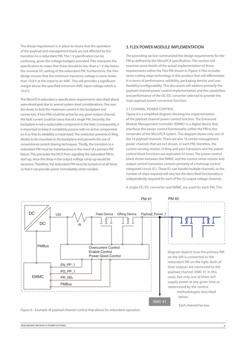
3.1 CHANNEL POWER CONTROLFigure 6 is a simplified diagram showing the implementation of the payload channel power control function. The Enhanced Module Management Controller (EMMC) is a digital device that interfaces the power control functionality within the PM to the remainder of the MicroTCA system. This diagram shows only one of the 16 payload channels. There are also 16 similar management power channels that are not shown. In each PM, therefore, the current sensing resistor, O-Ring and pass transistors and the power control block functions are replicated 32 times. The power control block shown between the EMMC and the current sense resistor and output control transistors consists primarily of a hotswap control integrated circuit (IC). These ICs can handle multiple channels, so the number of chips required will vary but the described functionality is independently required for each of the 32 output voltage channels.
A single DC/DC converter and EMMC are used for each PM. This
diagram depicts how the primary PM on the left is connected to the redundant PM on the right. Both of their outputs are connected to the payload channel (AMC #1 in this case), but only one of them will supply power at any given time as determined by the control
methodologies described below.
Each channel has two
DC
DC
12V
R
Pass Device ORing Device Payload_Power_1
Overcurrent ControlEnable ControlPower Good Control
EN_PP_1
PG_PP_1
PR_SEL
PMBus
EMMC
PMBus
AMC #1
PM #1 PM #2
Figure 6 - Example of payload channel control that allows for redundant operation
REDUNDANT MICROTCA POWER SYSTEMS 7
semiconductor switches in series. The O-Ring device prevents current from flowing in the reverse direction from the load into the power module. The pass device is used to enable or inhibit the output current and also to limit the value of the current to provide for functions such as soft start for hotswap and fault current limiting. The primary PM has both the pass and the O-Ring devices turned on to provide the lowest resistance current flow to the load. The redundant PM will have the pass device turned on so that it is ready to instantaneously deliver current if needed. Its O-Ring device, however, will be turned off to prevent any current flow into the redundant PM from the higher voltage level primary PM. In the event of a failure of the primary PM, the O-Ring device of the redundant PM can instantaneously provide current to the load through its intrinsic body diode. This connection will then be made more efficient by turning on the O-Ring device of the redundant PM to decrease its channel resistance when it becomes the primary PM.
Figure 6 also depicts two connections implemented with a Power Management Bus (PMBus™). The PMBus is a bidirectional serial digital bus that is central to the implementation of systems using digital power control and digital power management. This paper only describes its usage for this application, but additional information about the PMBus can be found in reference [6]. In this implementation the PMBus between the EMMC and the power control block is used so that the EMMC can monitor and change settings of the power control block during operation. The PMBus connection between the EMMC and the DC/DC converter is used so that the DC/DC converter can be programmed for the proper output voltage corresponding to its function as either a primary or redundant PM. The EMMC may also collect data on output current and temperature from the DC/DC converter. There is also, as depicted in Figures 4 and 5, an interconnection between the PMs so that each knows if the other is present in the system and its power good status.
3.2 DC/DC CONVERTER
As described previously, tightly controlled output voltage tolerances from the DC/DC converter are required in order for the PM redundancy feature of the MicroTCA platform to function properly. The Flex PM design uses the BMR453 DC/DC converter [8] that incorporates several breakthroughs in terms of performance and functionality. It is capable of digital power management via its PMBus interface, allowing on-the-fly adjustment of output voltage so that it can be defined as either a primary or redundant PM without interruption of power to the system. This same interface can also be used to collect useful data from the DC/DC for the purpose of communicating it to the rest of the system and to the outside world. This capability is useful for measuring values of such parameters as output current and operating temperature. The PMBus can also be used in the other direction for the purpose of modifying the DC/DC parameters and behavior during engineering development and system test. Fault limit set points and expected responses for such items as over current, over voltage and over temperature are a frequently used example of this capability.
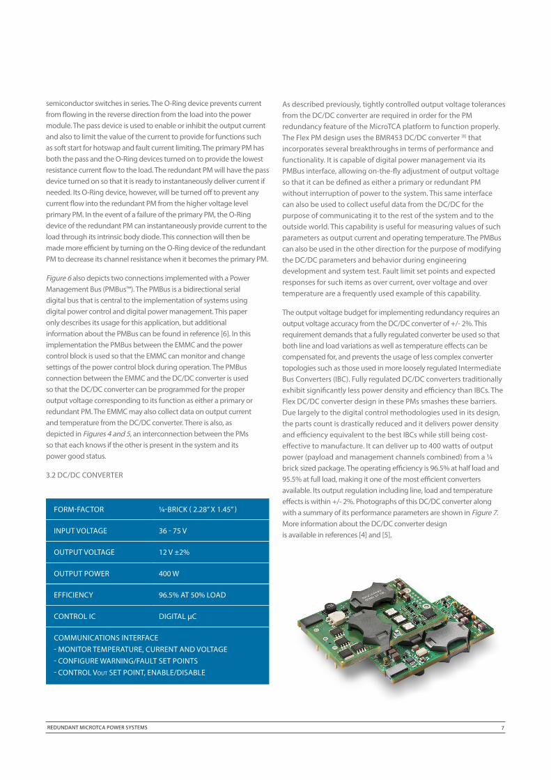
The output voltage budget for implementing redundancy requires an output voltage accuracy from the DC/DC converter of +/- 2%. This requirement demands that a fully regulated converter be used so that both line and load variations as well as temperature effects can be compensated for, and prevents the usage of less complex converter topologies such as those used in more loosely regulated Intermediate Bus Converters (IBC). Fully regulated DC/DC converters traditionally exhibit significantly less power density and efficiency than IBCs. The Flex DC/DC converter design in these PMs smashes these barriers. Due largely to the digital control methodologies used in its design, the parts count is drastically reduced and it delivers power density and efficiency equivalent to the best IBCs while still being cost-effective to manufacture. It can deliver up to 400 watts of output power (payload and management channels combined) from a ¼ brick sized package. The operating efficiency is 96.5% at half load and 95.5% at full load, making it one of the most efficient converters available. Its output regulation including line, load and temperature effects is within +/- 2%. Photographs of this DC/DC converter along with a summary of its performance parameters are shown in Figure 7. More information about the DC/DC converter design is available in references [4] and [5].
FORM-FACTOR ¼-BRICK ( 2.28” X 1.45” )
INPUT VOLTAGE 36 - 75 V
OUTPUT VOLTAGE 12 V ±2%
OUTPUT POWER 400 W
EFFICIENCY 96.5% AT 50% LOAD
CONTROL IC DIGITAL µC
COMMUNICATIONS INTERFACE- MONITOR TEMPERATURE, CURRENT AND VOLTAGE- CONFIGURE WARNING/FAULT SET POINTS- CONTROL Vout SET POINT, ENABLE/DISABLE
REDUNDANT MICROTCA POWER SYSTEMS 8
4. PERFORMANCE VERIFICATION
Previous parts of this paper have defined the requirements for redundancy as set forth in the MicroTCA specification and summarized Flex’s strategy and designs for meeting these requirements. Now it is time to see if it works in the “real world”. The purpose of this case study is to place the Flex standard PM into a standard MicroTCA enclosure along with AMC loads and a MCH and then verify that it meets the redundancy requirements for high availability when exposed to fault and maintenance conditions. The enclosure, MCH and AMC cards are all standard units from suppliers other than Flex. Test results will be shown for two scenarios – loss of input voltage or PM failure, and a hotswap maintenance action.
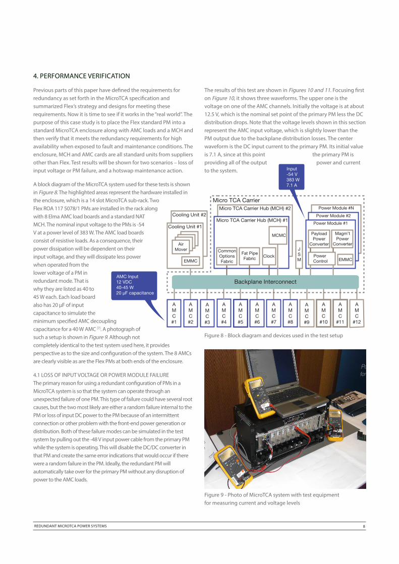
A block diagram of the MicroTCA system used for these tests is shown in Figure 8. The highlighted areas represent the hardware installed in the enclosure, which is a 14 slot MicroTCA sub-rack. Two Flex ROA 117 5078/1 PMs are installed in the rack along with 8 Elma AMC load boards and a standard NAT MCH. The nominal input voltage to the PMs is -54 V at a power level of 383 W. The AMC load boards consist of resistive loads. As a consequence, their power dissipation will be dependent on their input voltage, and they will dissipate less power when operated from the lower voltage of a PM in redundant mode. That is why they are listed as 40 to 45 W each. Each load board also has 20 µF of input capacitance to simulate the minimum specified AMC decoupling capacitance for a 40 W AMC [7]. A photograph of such a setup is shown in Figure 9. Although not completely identical to the test system used here, it provides perspective as to the size and configuration of the system. The 8 AMCs are clearly visible as are the Flex PMs at both ends of the enclosure.
4.1 LOSS OF INPUT VOLTAGE OR POWER MODULE FAILUREThe primary reason for using a redundant configuration of PMs in a MicroTCA system is so that the system can operate through an unexpected failure of one PM. This type of failure could have several root causes, but the two most likely are either a random failure internal to the PM or loss of input DC power to the PM because of an intermittent connection or other problem with the front-end power generation or distribution. Both of these failure modes can be simulated in the test system by pulling out the -48 V input power cable from the primary PM while the system is operating. This will disable the DC/DC converter in that PM and create the same error indications that would occur if there were a random failure in the PM. Ideally, the redundant PM will automatically take over for the primary PM without any disruption of power to the AMC loads.
4. PERFORMANCE VERIFICATION
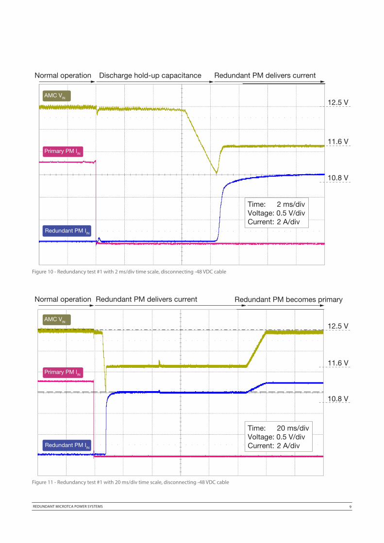
The results of this test are shown in Figures 10 and 11. Focusing first on Figure 10, it shows three waveforms. The upper one is the voltage on one of the AMC channels. Initially the voltage is at about 12.5 V, which is the nominal set point of the primary PM less the DC distribution drops. Note that the voltage levels shown in this section represent the AMC input voltage, which is slightly lower than the PM output due to the backplane distribution losses. The center waveform is the DC input current to the primary PM. Its initial value is 7.1 A, since at this point the primary PM is providing all of the output power and current to the system.
Cooling Unit #2
AMC#1
AMC#3
AMC#2
AMC#7
AMC#9
AMC#8
AMC
#12
AMC
#10
AMC#6
AMC#5
AMC#4
AMC
#11
AirMover
Cooling Unit #1
EMMC
Micro TCA CarrierMicro TCA Carrier Hub (MCH) #2
Micro TCA Carrier Hub (MCH) #1
MCMC
CommonOptionsFabric
ClockFat PipeFabric
JSM
Power Module #2
EMMCPower Control
PayloadPower
Converter
Magm’tPower
Converter
Power Module #1
Power Module #N
Backplane Interconnect
Input-54 V383 W7.1 A
AMC Input12 VDC40-45 W20 µF capacitance
Figure 8 - Block diagram and devices used in the test setup
Figure 9 - Photo of MicroTCA system with test equipment for measuring current and voltage levels
REDUNDANT MICROTCA POWER SYSTEMS 9
Figure 10 - Redundancy test #1 with 2 ms/div time scale, disconnecting -48 VDC cable
AMC VIN
Primary PM IIN
Redundant PM IIN
Normal operation Discharge hold-up capacitance Redundant PM delivers current
Time: 2 ms/divVoltage: 0.5 V/divCurrent: 2 A/div
12.5 V
11.6 V
10.8 V
AMC VIN
Primary PM IIN
Redundant PM IIN
Normal operation Redundant PM delivers current
Time: 20 ms/divVoltage: 0.5 V/divCurrent: 2 A/div
12.5 V
11.6 V
10.8 V
Redundant PM becomes primary
Figure 11 - Redundancy test #1 with 20 ms/div time scale, disconnecting -48 VDC cable
REDUNDANT MICROTCA POWER SYSTEMS 10
The lower trace is a similar measurement of the DC input current to the redundant PM. It appears to be zero, but the reader should keep in mind that at this point the redundant PM is turned on and operational, but is operating at zero output load because its O-Ring device is turned off. Because of the efficient “overhead” circuitry in the redundant PM, its input current appears in this view to be zero although it is actually a few milliamps.
The point at which the DC input power cable of the primary PM is removed is clearly visible in the figure as the primary PM input current goes instantly to zero. For the next few milliseconds the AMC input voltage will be supported by means of hold-up capacitance. For the first 6 ms, the AMC input voltage remains constant at about 12.5 V. During this time the primary PM DC/DC converter remains operating, taking its input current from the hold-up capacitance in the front-end of the PM. Since the PM DC/DC converter is fully regulated and operates down to an input voltage of 36 V, there is sufficient energy in the system to provide steady voltage to the AMC at full output current as the input hold-up capacitance discharges from the nominal 54 V to 36 V. When the primary PM DC/DC converter input voltage reaches 36 V, it shuts off. This event is evident in the upper trace as the AMC input voltage begins a downward decay. This decreasing input voltage is due to energy being drawn from the capacitance on the output of the primary PM and on the AMCs, and lasts for a little over 2 ms. Note that during this entire 8 ms period the input current to the PMs is either zero (in the case of the primary PM) or insignificant (for the redundant PM), and the
entire system is being powered from energy stored in
capacitance.
When the AMC input voltage reaches the set point of the redundant
PM, the body diode in its O-Ring device becomes forward biased
and it begins to deliver current to the AMCs. This is a very stringent
test for the PM, as its output load goes from zero to full load
essentially instantaneously. This takeover of power delivery by the
redundant PM is indicated in Figure 10 by two events. There is a
sudden rise in the redundant PM input current and there is an
increase in the AMC input voltage to 11.6 V, which is the set point of
the PM in its redundant role. Note that at no time does the AMC
input voltage reach 10.8 V, the value Flex has selected to insure
adequate margin for the minimum allowable 10.0 V value of the
AMC input specification. At the end of the time interval depicted in
Figure 10, the PMs have not switched roles. Even though the
redundant PM is delivering all of the system power, it is still defined
and operating as a redundant PM and is supplying output power at
a lower voltage than a primary PM.
The transition of its role from a redundant to a primary PM can be
observed by simply changing the time scale of the scope traces, as
shown in Figure 11. In this figure, the time base is set at 20 ms/div. It can
be seen that the system continues to operate as it was during the end
of Figure 10 for about another 100 ms. When the redundant PM begins
to deliver current, it notifies the MCH.
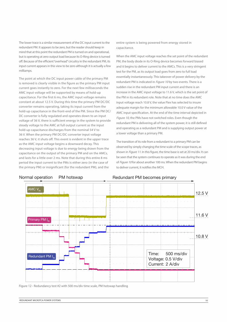
Figure 12 - Redundancy test #2 with 500 ms/div time scale, PM hotswap handling
AMC VIN
Primary PM IIN
Redundant PM IIN
Normal operation PM hotswap
Time: 500 ms/divVoltage: 0.5 V/divCurrent: 2 A/div
12.5 V
11.6 V
10.8 V
Redundant PM becomes primary
REDUNDANT MICROTCA POWER SYSTEMS 11
Because of the interconnection between the PMs shown in Figure 4 and 5, the redundant PM will be aware that the PM_OK signal of the primary PM has gone down, indicating a failure. At this point, the redundant PM assumes the role of primary PM and increases its output voltage accordingly. This transition can be seen clearly in Figure 11 as an increase in the AMC input voltage to 12.5 V. There is also a slight increase in the now primary PM’s input current due to the increase in output power from increasing the voltage on the resistive load. All of this can be accomplished in much less than 100 ms, but there is a built-in 100 ms “debouncer” before the role transition so that transient noise and glitches can be filtered out.
This test successfully demonstrates that unexpected PM or input voltage failures can be automatically accommodated by the redundant PM configuration without affecting the operation of the AMC loads.
4.2 HOTSWAP Redundant MicroTCA systems are configured so that a PM may be replaced in the field without disrupting operation of the system. This type of maintenance action would be initiated if it was felt that a given PM was degrading in performance or if PMs were replaced for upgrade purposes. In this case we are dealing with a deliberate action rather than the unplanned result of a failure as in the preceding test. The same scenario is applicable in systems where the MCH changes responsibilities between PMs to
balance the load over time and thus improve reliability. The test described here was done to verify that the AMCs operate without disruption during both maintenance replacement of a PM and also when the MCH decides to shift the role of the redundant PM.
In this test, the primary PM was hotswapped while the system was running. Each of the Flex PMs has a handle on its exterior faceplate that the user pulls to initiate extraction of the PM from the system. There is a sensor on the handle that tells the PM to initiate a hotswap sequence when the handle is activated, and the PM will then notify the MCH that it is about to be extracted from the system. Upon receiving this notification, the MCH will begin sending commands to the primary PM telling it to disable payload and management power. There will be one command issued per channel so that the deactivation can be done in a controlled manner to avoid large amounts of transient currents. As each channel is deactivated by the primary PM, the corresponding channel of the redundant PM automatically takes over supplying current to that channel. This operation can be seen in Figure 12. The scope traces in this figure represent the same connection points as in the previous two figures, the upper trace being the AMC input voltage and the lower two traces the input currents to the two PMs.
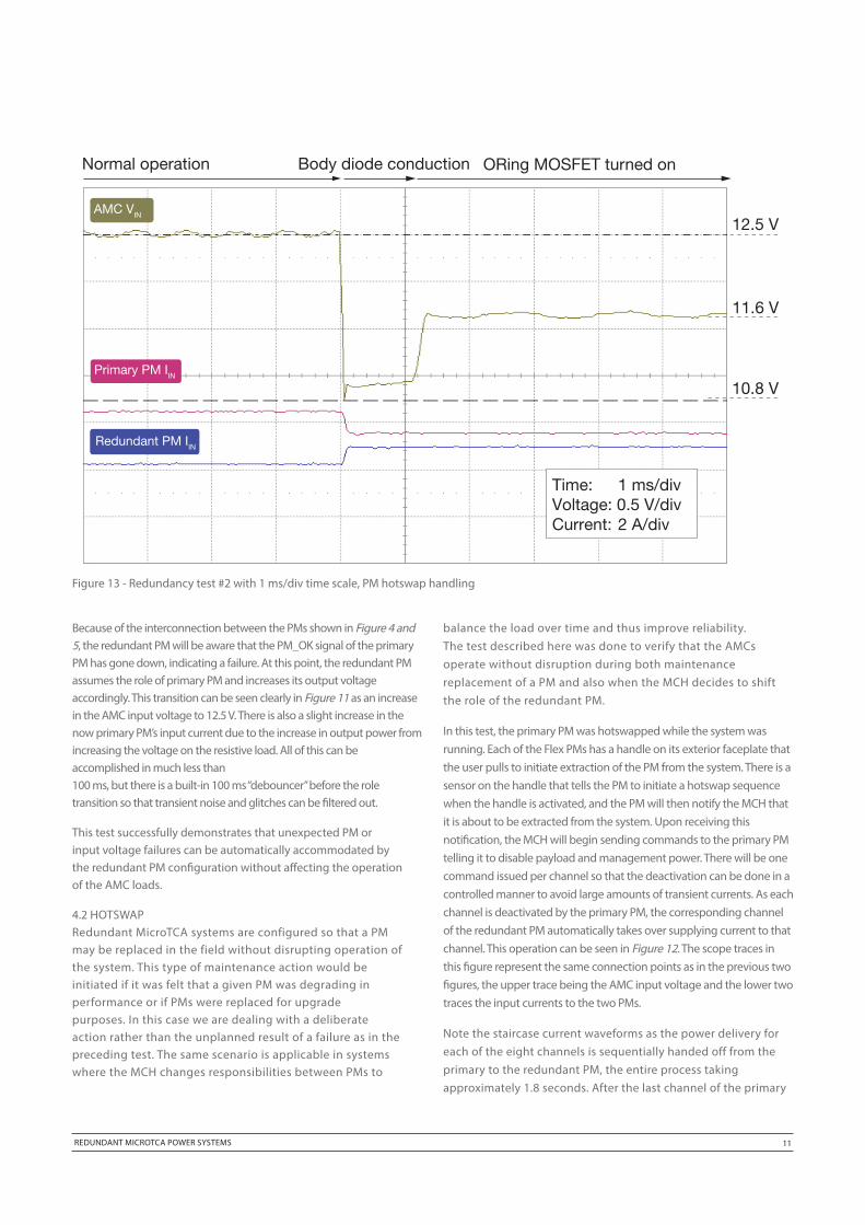
Note the staircase current waveforms as the power delivery for each of the eight channels is sequentially handed off from the primary to the redundant PM, the entire process taking approximately 1.8 seconds. After the last channel of the primary
AMC VIN
Primary PM IIN
Redundant PM IIN
Normal operation Body diode conduction
Time: 1 ms/divVoltage: 0.5 V/divCurrent: 2 A/div
12.5 V
11.6 V
10.8 V
ORing MOSFET turned on
Figure 13 - Redundancy test #2 with 1 ms/div time scale, PM hotswap handling
REDUNDANT MICROTCA POWER SYSTEMS 12
PM has been deactivated, it is reset and a blue LED is activated
on its front panel telling the user that it is safe to extract the PM.
During the reset of the primary PM, the redundant PM sees that
the PM_OK signal from the primary PM is gone, and then changes
its role from redundant to primary and increases its output voltage.
Note that the upper trace showing the AMC input voltage is
arbitrarily connected to the fourth channel to be transferred from
the primary to the redundant PM. Consequently, its voltage remains
at 12.5 V until the fourth transfer and then is reduced to the
redundant PM voltage level until the transfer of roles between
redundant and primary, at which point it returns to 12.5 V. Other
channels will see more or less time at the lower operating voltage.
It is instructive to take a closer look at the leading edge of the
power transfer on this channel as shown in Figure 13. All the
scope connections and vertical scaling remain the same as the
previous figure and only the timebase is changed to 1 ms/div
so that more detail of the actual power transfer may be seen.
Note first of all that the channel voltage always remains above
10.8V so that the MicroTCA AMC specifications are again given
adequate margin. The voltage waveform also illustrates the
behavior of the channel power control operation. When the
channel is deactivated in the primary PM, there is a sudden
drop in voltage as the redundant PM supplies current to the
channel through its O-Ring device body diode. During this
time, the redundant channel pass device is turned on and its
O-Ring device is turned off. Within a millisecond, the O-Ring
device is turned on to reduce the voltage drop and to increase
the channel efficiency. It is clear from the scope trace that there
is about 0.6 V less drop with the O-Ring device turned on. The
redundant PM then continues to supply current at the reduced
output voltage until it assumes the role of primary PM at the
conclusion of the hotswap sequence and increases its nominal
output voltage to 12.5 V.
This test successfully demonstrates that planned maintenance
hotswap actions and MCH initiated transfer of primary / redundant
roles during operation are supported by the MicroTCA redundancy
specifications and the Flex PMs.
5. SUMMARY AND CONCLUSIONS
This case study demonstrates that standard MicroTCA components can be used to implement high availability systems by means of redundancy. A new high efficiency high power density DC/DC converter is described that is used within the standard Flex PM and is responsible for many of the industry-leading performance attributes of the PM. Specifically, it is shown that:
• ALL THE RELATED PROVISIONS OF MTCA.0 R1.0 CAN BE MET
• CONTINUOUS OPERATION IS MAINTAINED DURING - FAILURE OF A PM - LOSS OF INPUT POWER TO A PM - HOTSWAP OF A PM - MCH INITIATED TRANSFER OF ROLES
• INTEROPERABILITY IS ACHIEVED BETWEEN THE PM AND MCH
• THE DC/DC CONVERTER OFFERS A UNIQUE COMBINATION OF EFFICIENCY, POWER DENSITY AND OUTPUT VOLTAGE REGULATION
• CAPABILITY OF THE DC/DC TO ADJUST THE OUTPUT VOLTAGE DURING OPERATION AND MAINTAIN PRECISE REGULATION TOLERANCES IS KEY TO SUCCESS IN REDUNDANT APPLICATIONS
All of these objectives are met using only standard MicroTCA components. Components from various suppliers, if properly designed to the MicroTCA specifications, should successfully operate together to allow high availability solutions by means of PM redundancy. This is an important result, since the alternative would be to attempt customized proprietary power control implementations. In addition to being very labor intensive and expensive, proprietary solutions will increase technical risk and time-to-market. Approaches such as the one presented here represent a cost-effective method of achieving high performance, high reliability and availability and a streamlined system design process without the need for customized circuit design.
REDUNDANT MICROTCA POWER SYSTEMS 13
7. GLOSSARY
AMC Advanced Mezzanine Card
CU Cooling Unit
EMMC Enhanced Module Management Controller
IBC Intermediate Bus Converter
IC Integrated Circuit
ICT Information Communication Technology
LED Light Emitting Diode
MCH MicroTCA Carrier Hub
MicroTCA™ Micro Telecommunications Computing Architecture
OEM Original Equipment Manufacturer
PM MicroTCA Power Module
PMBus™ Power Management Bus
8. REFERENCES
[1] MicroTCA base specification R1.0, PICMG, 6 July 2006
[2] MicroTCA Power Module Preliminary Datasheet, Flex Power Modules, May 2008*
[3] Advanced TCA Summit Europe 2007 - Performance, Cost and Reliability Considerations in a MicroTCA Power System*
[4] APEC 2007 - Implications of Digital Control and Management for a High Performance Isolated DC/DC*
[5] Digital Power Europe 2007 - Digital Control in a MicroTCA Power System*
[6] Digital Power Technical Brief, Flex Power Modules, November 2006*
[7] AdvancedMC base specification R2.0, PICMG, 15 November 2006
[8] BMR453 DC/DC converter Technical Specification, Flex Power Modules, June 2008*
* All referenced papers and data sheets can be found at Flex Power Modules’ web site: https://flex.com/expertise/power/modules
TrademarksFlex and the Flex logotype is the trademark or registered trademark of Flex Inc. All other product or service names mentioned in this document are trademarks of their respective companies.
EAB-08:050762 Uen Rev C Feb 2018