Embed Size (px)
Citation preview
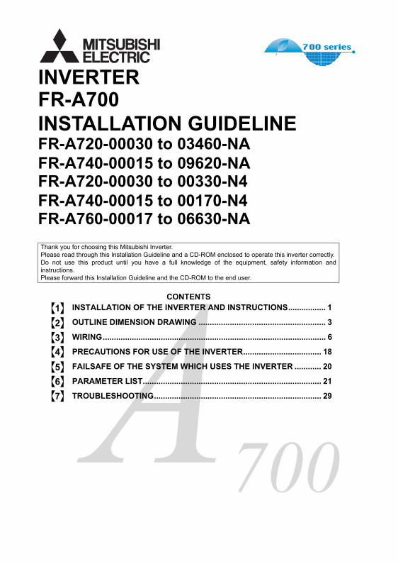
FR-A700INSTALLATION GUIDELINEFR-A720-00030 to 03460-NAFR-A740-00015 to 09620-NAFR-A720-00030 to 00330-N4FR-A740-00015 to 00170-N4FR-A760-00017 to 06630-NA
INVERTER
700
CONTENTSINSTALLATION OF THE INVERTER AND INSTRUCTIONS................. 1
OUTLINE DIMENSION DRAWING ......................................................... 3
WIRING.................................................................................................... 6
PRECAUTIONS FOR USE OF THE INVERTER................................... 18
FAILSAFE OF THE SYSTEM WHICH USES THE INVERTER ............ 20
PARAMETER LIST................................................................................ 21
TROUBLESHOOTING........................................................................... 29
Thank you for choosing this Mitsubishi Inverter.Please read through this Installation Guideline and a CD-ROM enclosed to operate this inverter correctly.Do not use this product until you have a full knowledge of the equipment, safety information andinstructions.Please forward this Installation Guideline and the CD-ROM to the end user.
1234567
1. Electric Shock Prevention
2. Fire Prevention
3. Injury Prevention
4. Additional InstructionsAlso the following points must be noted to prevent an accidental failure,injury, electric shock, etc.
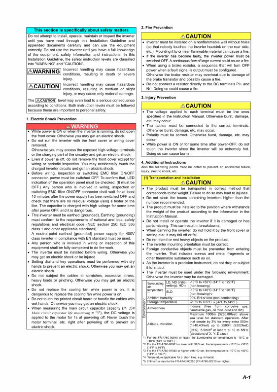
This section is specifically about safety mattersDo not attempt to install, operate, maintain or inspect the inverteruntil you have read through this Installation Guideline andappended documents carefully and can use the equipmentcorrectly. Do not use the inverter until you have a full knowledgeof the equipment, safety information and instructions. In thisInstallation Guideline, the safety instruction levels are classifiedinto "WARNING" and "CAUTION".
Incorrect handling may cause hazardousconditions, resulting in death or severeinjury.Incorrect handling may cause hazardousconditions, resulting in medium or slightinjury, or may cause only material damage.
The level may even lead to a serious consequenceaccording to conditions. Both instruction levels must be followedbecause these are important to personal safety.
• While power is ON or when the inverter is running, do not openthe front cover. Otherwise you may get an electric shock.
• Do not run the inverter with the front cover or wiring coverremoved.Otherwise you may access the exposed high-voltage terminalsor the charging part of the circuitry and get an electric shock.
• Even if power is off, do not remove the front cover except forwiring or periodic inspection. You may accidentally touch thecharged inverter circuits and get an electric shock.
• Before wiring, inspection or switching EMC filter ON/OFFconnector, power must be switched OFF. To confirm that, LEDindication of the operation panel must be checked. (It must beOFF.) Any person who is involved in wiring, inspection orswitching EMC filter ON/OFF connector shall wait for at least10 minutes after the power supply has been switched OFF andcheck that there are no residual voltage using a tester or thelike. The capacitor is charged with high voltage for some timeafter power OFF, and it is dangerous.
• This inverter must be earthed (grounded). Earthing (grounding)must conform to the requirements of national and local safetyregulations and electrical code (NEC section 250, IEC 536class 1 and other applicable standards).A neutral-point earthed (grounded) power supply for 400Vclass inverter in compliance with EN standard must be used.
• Any person who is involved in wiring or inspection of thisequipment shall be fully competent to do the work.
• The inverter must be installed before wiring. Otherwise youmay get an electric shock or be injured.
• Setting dial and key operations must be performed with dryhands to prevent an electric shock. Otherwise you may get anelectric shock.
• Do not subject the cables to scratches, excessive stress,heavy loads or pinching. Otherwise you may get an electricshock.
• Do not replace the cooling fan while power is on. It isdangerous to replace the cooling fan while power is on.
• Do not touch the printed circuit board or handle the cables withwet hands. Otherwise you may get an electric shock.
• When measuring the main circuit capacitor capacity (Pr. 259Main circuit capacitor life measuring = "1"), the DC voltage isapplied to the motor for 1s at powering off. Never touch themotor terminal, etc. right after powering off to prevent anelectric shock.
WARNING
CAUTION
CAUTION
WARNING
• Inverter must be installed on a nonflammable wall without holes(so that nobody touches the inverter heatsink on the rear side,etc.). Mounting it to or near flammable material can cause a fire.
• If the inverter has become faulty, the inverter power must beswitched OFF. A continuous flow of large current could cause a fire.
• When using a brake resistor, a sequence that will turn OFFpower when a fault signal is output must be configured.Otherwise the brake resistor may overheat due to damage ofthe brake transistor and possibly cause a fire.
• Do not connect a resistor directly to the DC terminals P/+ andN/-. Doing so could cause a fire.
• The voltage applied to each terminal must be the onesspecified in the Instruction Manual. Otherwise burst, damage,etc. may occur.
• The cables must be connected to the correct terminals.Otherwise burst, damage, etc. may occur.
• Polarity must be correct. Otherwise burst, damage, etc. mayoccur.
• While power is ON or for some time after power-OFF, do nottouch the inverter since the inverter will be extremely hot.Doing so can cause burns.
(1) Transportation and installation
• The product must be transported in correct method thatcorresponds to the weight. Failure to do so may lead to injuries.
• Do not stack the boxes containing inverters higher than thenumber recommended.
• The product must be installed to the position where withstandsthe weight of the product according to the information in theInstruction Manual.
• Do not install or operate the inverter if it is damaged or hasparts missing. This can result in breakdowns.
• When carrying the inverter, do not hold it by the front cover orsetting dial; it may fall off or fail.
• Do not stand or rest heavy objects on the product.• The inverter mounting orientation must be correct.• Foreign conductive objects must be prevented from entering
the inverter. That includes screws and metal fragments orother flammable substance such as oil.
• As the inverter is a precision instrument, do not drop or subjectit to impact.
• The inverter must be used under the following environment:Otherwise the inverter may be damaged.
CAUTION
CAUTION
CAUTION
Env
ironm
ent
Surroundingairtemperature *1
LD, ND (initial setting), HD*3
-10°C to +50°C (14°F to 122°F)(non-freezing)
SLD -10°C to +40°C (14°F to 104°F)(non-freezing)*2
Ambient humidity 90% RH or less (non-condensing)Storage temperature -20°C to +65°C *4 (-4°F to 149°F)
Atmosphere Indoors (free from corrosive gas,flammable gas, oil mist, dust and dirt)
Altitude, vibration
Maximum 1000m (3280.80feet) abovesea level for standard operation. Afterthat derate by 3% for every extra 500m(1640.40feet) up to 2500m (8202feet)(91%). 5.9m/s2 or less *5 at 10 to 55Hz(directions of X, Y, Z axes)
*1 For the FR-A760-00840 or lower, the Surrounding air temperature is -10°C to+40°C (14°F to 104°F)
*2 For the FR-A760-00061 or lower with SLD set, the temperature is -10°C to +30°C(14°F to 86°F)
*3 For the FR-A760-01040 or higher with HD set, the temperature is -10°C to +40°C(14°F to 104°F)
*4 Temperature applicable for a short time, e.g. in transit.*5 2.9m/s2 or less for the FR-A740-03250 (FR-A760-02210) or higher.
A-1
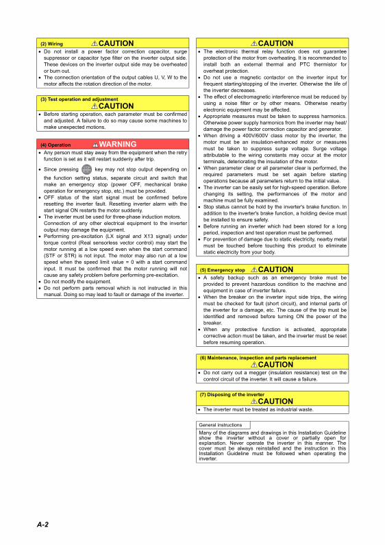
(2) Wiring• Do not install a power factor correction capacitor, surge
suppressor or capacitor type filter on the inverter output side.These devices on the inverter output side may be overheatedor burn out.
• The connection orientation of the output cables U, V, W to themotor affects the rotation direction of the motor.
(3) Test operation and adjustment
• Before starting operation, each parameter must be confirmedand adjusted. A failure to do so may cause some machines tomake unexpected motions.
(4) Operation• Any person must stay away from the equipment when the retry
function is set as it will restart suddenly after trip.
• Since pressing key may not stop output depending on
the function setting status, separate circuit and switch thatmake an emergency stop (power OFF, mechanical brakeoperation for emergency stop, etc.) must be provided.
• OFF status of the start signal must be confirmed beforeresetting the inverter fault. Resetting inverter alarm with thestart signal ON restarts the motor suddenly.
• The inverter must be used for three-phase induction motors.Connection of any other electrical equipment to the inverteroutput may damage the equipment.
• Performing pre-excitation (LX signal and X13 signal) undertorque control (Real sensorless vector control) may start themotor running at a low speed even when the start command(STF or STR) is not input. The motor may also run at a lowspeed when the speed limit value = 0 with a start commandinput. It must be confirmed that the motor running will notcause any safety problem before performing pre-excitation.
• Do not modify the equipment.• Do not perform parts removal which is not instructed in this
manual. Doing so may lead to fault or damage of the inverter.
CAUTION
CAUTION
WARNING
• The electronic thermal relay function does not guaranteeprotection of the motor from overheating. It is recommended toinstall both an external thermal and PTC thermistor foroverheat protection.
• Do not use a magnetic contactor on the inverter input forfrequent starting/stopping of the inverter. Otherwise the life ofthe inverter decreases.
• The effect of electromagnetic interference must be reduced byusing a noise filter or by other means. Otherwise nearbyelectronic equipment may be affected.
• Appropriate measures must be taken to suppress harmonics.Otherwise power supply harmonics from the inverter may heat/damage the power factor correction capacitor and generator.
• When driving a 400V/600V class motor by the inverter, themotor must be an insulation-enhanced motor or measuresmust be taken to suppress surge voltage. Surge voltageattributable to the wiring constants may occur at the motorterminals, deteriorating the insulation of the motor.
• When parameter clear or all parameter clear is performed, therequired parameters must be set again before startingoperations because all parameters return to the initial value.
• The inverter can be easily set for high-speed operation. Beforechanging its setting, the performances of the motor andmachine must be fully examined.
• Stop status cannot be hold by the inverter's brake function. Inaddition to the inverter's brake function, a holding device mustbe installed to ensure safety.
• Before running an inverter which had been stored for a longperiod, inspection and test operation must be performed.
• For prevention of damage due to static electricity, nearby metalmust be touched before touching this product to eliminatestatic electricity from your body.
(5) Emergency stop• A safety backup such as an emergency brake must be
provided to prevent hazardous condition to the machine andequipment in case of inverter failure.
• When the breaker on the inverter input side trips, the wiringmust be checked for fault (short circuit), and internal parts ofthe inverter for a damage, etc. The cause of the trip must beidentified and removed before turning ON the power of thebreaker.
• When any protective function is activated, appropriatecorrective action must be taken, and the inverter must be resetbefore resuming operation.
(6) Maintenance, inspection and parts replacement
• Do not carry out a megger (insulation resistance) test on thecontrol circuit of the inverter. It will cause a failure.
(7) Disposing of the inverter
• The inverter must be treated as industrial waste.
General instructionsMany of the diagrams and drawings in this Installation Guidelineshow the inverter without a cover or partially open forexplanation. Never operate the inverter in this manner. Thecover must be always reinstalled and the instruction in thisInstallation Guideline must be followed when operating theinverter.
CAUTION
CAUTION
CAUTION
CAUTION
A-2
1
INSTALLATION OF THEINVERTER AND INSTRUCTIONS
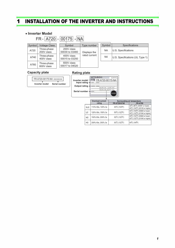
1 INSTALLATION OF THE INVERTER AND INSTRUCTIONS
Capacity plate
Inverter model Serial number
Rating plate
00175 NA
FR-A720-00175-NA
- FR - -A720
Symbol
A720
Voltage Class
Three-phase
200V class
A740
A760
Three-phase
400V class
Three-phase
600V class
Symbol
200V class
00030 to 03460 Displays the
rated current
Type number
400V class
00015 to 03250
600V class
00017 to 04020
Inverter modelInput rating
Output rating
Serial number
FR-A720-00175-NA
LD (50 C) XXA
SLD (40 C) XXA
ND (50 C) XXA
HD (50 C) XXA
30 C (86 F) (00061 or lower)
40 C (104 F) (00120 or higher)
40 C (104 F) (00840 or lower)
50 C (122 F) (01040 or higher)
40 C (104 F)
• Inverter Model
Overload current rating
Surrounding air temperature
FR-A720/A740 FR-A760
40 C (104 F)
50 C (122 F)
50 C (122 F)
50 C (122 F)
110% 60s, 120% 3s
120% 60s, 150% 3s
150% 60s, 200% 3s
200% 60s, 250% 3s
SLD
LD
ND
HD
Symbol
NA U.S. Specifications
Specifications
N4 U.S. Specifications (UL Type 1)
40 C (104 F) (00840 or lower)
50 C (122 F) (01040 or higher)
2
INSTALLATION OF THE INVERTER AND INSTRUCTIONS
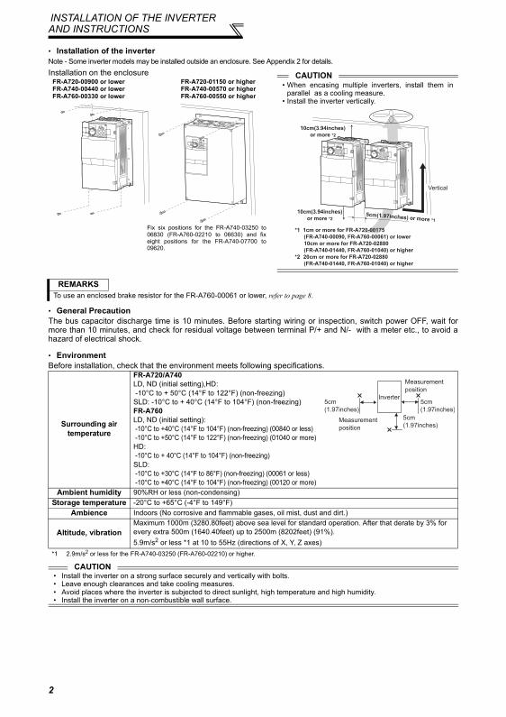
• Installation of the inverterNote - Some inverter models may be installed outside an enclosure. See Appendix 2 for details.
• General PrecautionThe bus capacitor discharge time is 10 minutes. Before starting wiring or inspection, switch power OFF, wait formore than 10 minutes, and check for residual voltage between terminal P/+ and N/- with a meter etc., to avoid ahazard of electrical shock.
• EnvironmentBefore installation, check that the environment meets following specifications.
Installation on the enclosure
REMARKSTo use an enclosed brake resistor for the FR-A760-00061 or lower, refer to page 8.
Surrounding airtemperature
FR-A720/A740LD, ND (initial setting),HD: -10°C to + 50°C (14°F to 122°F) (non-freezing)SLD: -10°C to + 40°C (14°F to 104°F) (non-freezing)FR-A760LD, ND (initial setting): -10°C to +40°C (14°F to 104°F) (non-freezing) (00840 or less) -10°C to +50°C (14°F to 122°F) (non-freezing) (01040 or more)HD: -10°C to + 40°C (14°F to 104°F) (non-freezing)SLD: -10°C to +30°C (14°F to 86°F) (non-freezing) (00061 or less) -10°C to +40°C (14°F to 104°F) (non-freezing) (00120 or more)
Ambient humidity 90%RH or less (non-condensing)Storage temperature -20°C to +65°C (-4°F to 149°F)
Ambience Indoors (No corrosive and flammable gases, oil mist, dust and dirt.)
Altitude, vibrationMaximum 1000m (3280.80feet) above sea level for standard operation. After that derate by 3% for every extra 500m (1640.40feet) up to 2500m (8202feet) (91%).5.9m/s2 or less *1 at 10 to 55Hz (directions of X, Y, Z axes)
*1 2.9m/s2 or less for the FR-A740-03250 (FR-A760-02210) or higher.
CAUTION• Install the inverter on a strong surface securely and vertically with bolts.• Leave enough clearances and take cooling measures.• Avoid places where the inverter is subjected to direct sunlight, high temperature and high humidity.• Install the inverter on a non-combustible wall surface.
FR-A720-00900 or lowerFR-A740-00440 or lowerFR-A760-00330 or lower
FR-A720-01150 or higherFR-A740-00570 or higherFR-A760-00550 or higher
Fix six positions for the FR-A740-03250 to06830 (FR-A760-02210 to 06630) and fixeight positions for the FR-A740-07700 to09620.
CAUTION• When encasing multiple inverters, install them in
parallel as a cooling measure.• Install the inverter vertically.
5cm(1.97inches) or more *1
10cm(3.94inches)
or more *2
10cm(3.94inches)
or more *2
*1 1cm or more for FR-A720-00175
(FR-A740-00090, FR-A760-00061) or lower
10cm or more for FR-A720-02880
(FR-A740-01440, FR-A760-01040) or higher
*2 20cm or more for FR-A720-02880
(FR-A740-01440, FR-A760-01040) or higher
Vertical
5cm
(1.97inches)
5cm
(1.97inches)
5cm
(1.97inches)
Measurement
position
Measurement
position
Inverter
OUTLINE DIMENSION DRAWING
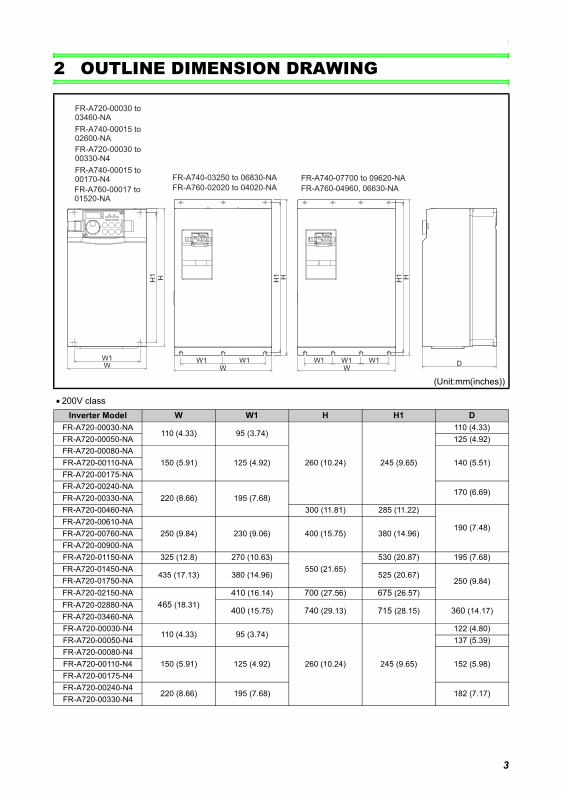
2 OUTLINE DIMENSION DRAWING
• 200V class
(Unit:mm(inches))
Inverter Model W W1 H H1 DFR-A720-00030-NA
110 (4.33) 95 (3.74)
260 (10.24) 245 (9.65)
110 (4.33)FR-A720-00050-NA 125 (4.92)FR-A720-00080-NA
150 (5.91) 125 (4.92) 140 (5.51)FR-A720-00110-NAFR-A720-00175-NAFR-A720-00240-NA
220 (8.66) 195 (7.68)170 (6.69)
FR-A720-00330-NAFR-A720-00460-NA 300 (11.81) 285 (11.22)
190 (7.48)FR-A720-00610-NA
250 (9.84) 230 (9.06) 400 (15.75) 380 (14.96)FR-A720-00760-NAFR-A720-00900-NAFR-A720-01150-NA 325 (12.8) 270 (10.63)
550 (21.65)530 (20.87) 195 (7.68)
FR-A720-01450-NA435 (17.13) 380 (14.96) 525 (20.67)
250 (9.84)FR-A720-01750-NAFR-A720-02150-NA
465 (18.31)410 (16.14) 700 (27.56) 675 (26.57)
FR-A720-02880-NA400 (15.75) 740 (29.13) 715 (28.15) 360 (14.17)
FR-A720-03460-NAFR-A720-00030-N4
110 (4.33) 95 (3.74)
260 (10.24) 245 (9.65)
122 (4.80)FR-A720-00050-N4 137 (5.39)FR-A720-00080-N4
150 (5.91) 125 (4.92) 152 (5.98)FR-A720-00110-N4FR-A720-00175-N4FR-A720-00240-N4
220 (8.66) 195 (7.68) 182 (7.17)FR-A720-00330-N4
WW1 W1 W1
WW1 W1
H1 H H1 HH
WW1
D
H1
FR-A720-00030 to 03460-NA
FR-A740-00015 to 02600-NA
FR-A720-00030 to 00330-N4
FR-A740-00015 to 00170-N4 FR-A740-03250 to 06830-NA
FR-A760-02020 to 04020-NA
FR-A740-07700 to 09620-NA
FR-A760-04960, 06630-NAFR-A760-00017 to 01520-NA
3
OUTLINE DIMENSION DRAWING
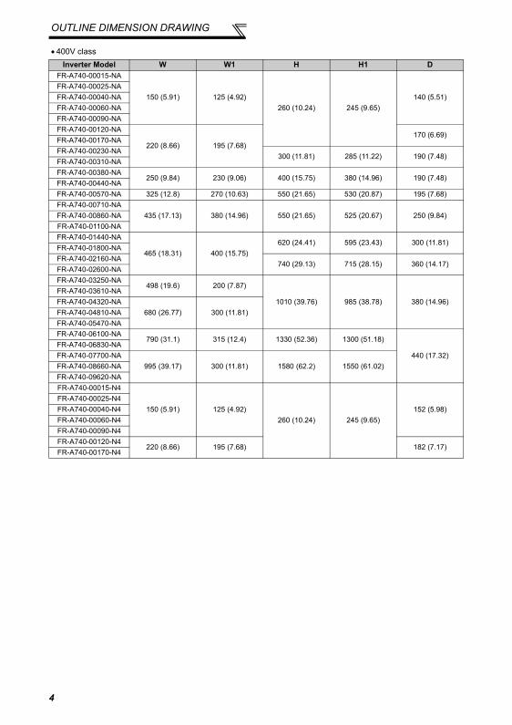
• 400V classInverter Model W W1 H H1 D
FR-A740-00015-NA
150 (5.91) 125 (4.92)260 (10.24) 245 (9.65)
140 (5.51)FR-A740-00025-NAFR-A740-00040-NAFR-A740-00060-NAFR-A740-00090-NAFR-A740-00120-NA
220 (8.66) 195 (7.68)170 (6.69)
FR-A740-00170-NAFR-A740-00230-NA
300 (11.81) 285 (11.22) 190 (7.48)FR-A740-00310-NAFR-A740-00380-NA
250 (9.84) 230 (9.06) 400 (15.75) 380 (14.96) 190 (7.48)FR-A740-00440-NAFR-A740-00570-NA 325 (12.8) 270 (10.63) 550 (21.65) 530 (20.87) 195 (7.68)FR-A740-00710-NA
435 (17.13) 380 (14.96) 550 (21.65) 525 (20.67) 250 (9.84)FR-A740-00860-NAFR-A740-01100-NAFR-A740-01440-NA
465 (18.31) 400 (15.75)620 (24.41) 595 (23.43) 300 (11.81)
FR-A740-01800-NAFR-A740-02160-NA
740 (29.13) 715 (28.15) 360 (14.17)FR-A740-02600-NAFR-A740-03250-NA
498 (19.6) 200 (7.87)
1010 (39.76) 985 (38.78) 380 (14.96)FR-A740-03610-NAFR-A740-04320-NA
680 (26.77) 300 (11.81)FR-A740-04810-NAFR-A740-05470-NAFR-A740-06100-NA
790 (31.1) 315 (12.4) 1330 (52.36) 1300 (51.18)
440 (17.32)FR-A740-06830-NAFR-A740-07700-NA
995 (39.17) 300 (11.81) 1580 (62.2) 1550 (61.02)FR-A740-08660-NAFR-A740-09620-NAFR-A740-00015-N4
150 (5.91) 125 (4.92)260 (10.24) 245 (9.65)
152 (5.98)FR-A740-00025-N4FR-A740-00040-N4FR-A740-00060-N4FR-A740-00090-N4FR-A740-00120-N4
220 (8.66) 195 (7.68) 182 (7.17)FR-A740-00170-N4
4
OUTLINE DIMENSION DRAWING
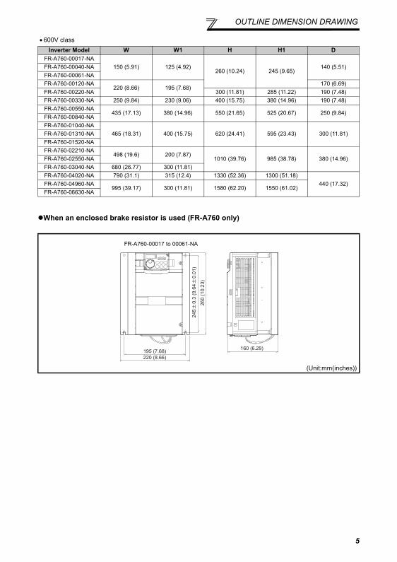
• 600V class
When an enclosed brake resistor is used (FR-A760 only)
Inverter Model W W1 H H1 DFR-A760-00017-NA
150 (5.91) 125 (4.92)260 (10.24) 245 (9.65)
140 (5.51)FR-A760-00040-NAFR-A760-00061-NAFR-A760-00120-NA
220 (8.66) 195 (7.68)170 (6.69)
FR-A760-00220-NA 300 (11.81) 285 (11.22) 190 (7.48)FR-A760-00330-NA 250 (9.84) 230 (9.06) 400 (15.75) 380 (14.96) 190 (7.48)FR-A760-00550-NA
435 (17.13) 380 (14.96) 550 (21.65) 525 (20.67) 250 (9.84)FR-A760-00840-NAFR-A760-01040-NA
465 (18.31) 400 (15.75) 620 (24.41) 595 (23.43) 300 (11.81)FR-A760-01310-NAFR-A760-01520-NAFR-A760-02210-NA
498 (19.6) 200 (7.87)1010 (39.76) 985 (38.78) 380 (14.96)FR-A760-02550-NA
FR-A760-03040-NA 680 (26.77) 300 (11.81)FR-A760-04020-NA 790 (31.1) 315 (12.4) 1330 (52.36) 1300 (51.18)
440 (17.32)FR-A760-04960-NA995 (39.17) 300 (11.81) 1580 (62.20) 1550 (61.02)
FR-A760-06630-NA
(Unit:mm(inches))
195 (7.68)220 (8.66)
160 (6.29)
260
(10.
23)
245
0.
3 (9
.64
0.
01)
FR-A760-00017 to 00061-NA
5
6
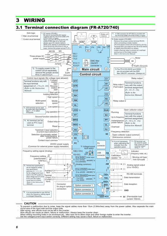
Terminal connection diagram (FR-A720/740)
3 WIRING3.1 Terminal connection diagram (FR-A720/740)
CAUTION· To prevent a malfunction due to noise, keep the signal cables more than 10cm (3.94inches) away from the power cables. Also separate the main
circuit wire of the input side and the output side.· After wiring, wire offcuts must not be left in the inverter.
Wire offcuts can cause an alarm, failure or malfunction. Always keep the inverter clean.When drilling mounting holes in an enclosure etc., take care not to allow chips and other foreign matter to enter the inverter.
· Set the voltage/current input switch correctly. Different setting may cause a fault, failure or malfunction.
R/L1
S/L2
T/L3
R1/L11
S1/L21
PC
10E(+10V)
10(+5V)
2
(Analog common)
23
1
1
4
Jumper
C1
B1
A1
U
V
W
P1
0 to ±10VDC
*1
0 to 5VDC0 to 10VDC
MC
Main circuit
Control circuit
C2
B2
A2
IM
0 to 20mADC
AU
PTC
TXD+
TXD-
RXD+
RXD-
SGGND
SIN
K
SO
UR
CE
*4
*3
*5
STF
STR
STOP
RH
RM
RL
JOG
RT
MRS
RES
AU
CS
SD
RUN
SU
IPF
OL
FU
SE
(+)(-)
5
ON
OFF
VCC
(+)(-)
5V
*2 Earth (Ground)
PX PR N/-P/+
*8
*3. JOG terminal can be usedas pulse train input terminal.Use Pr. 291 to selectJOG/pulse.
Main circuit terminal
Control circuit terminal
Three-phase AC
power supply
MCCB
Jumper
Earth
(Ground)
EMC filter
ON/OFF
connecter
Earth(Ground)
selectable
selectable0 to ±5VDC *5
4 to 20mADC
0 to 5VDC0 to 10VDC
selectable *5
Option connector 1
Option connector 2
Option connector 3
Connector
for plug-in option
connection
Frequency setting signal (Analog)
Frequency setting
potentiometer1/2W1kΩ
*6
Control input signals (No voltage input allowed)Forwardrotation
startReverserotation
start
Start self-holding selection
Terminal functions vary with
the input terminal
assignment (Pr. 178 to Pr. 189)
Middlespeed
High speed
Low speed
Multi-speed
selection
Jog operation
Second function selection
Output stop
Reset
Terminal 4 input selection(Current input selection)
Selection of automatic restart after instantaneous
power failure
USB
connector
PU
connector
Terminating resistor
Data reception
Data transmission
RS-485 terminals
Open collector output common
Sink/source common
Frequency detection
Running
Up to frequency
Instantaneous power failure
Overload
Terminal functions
vary with the output
terminal assignment
(Pr. 190 to Pr. 194)
Open collector output
(Permissible load
current 100mA)
Relay output 2
Relay output 1
(Fault output)
Terminal functions
vary with the output
terminal assignment
(Pr. 195, Pr. 196)
Relay output
Motor
*4. AU terminal can be
used as PTC input
terminal.
*2. To supply power to the control circuit separately, remove the jumper across R1/L11 and S1/L21.
*10. It is not necessary when calibrating the indicator from the operation panel.
*6. It is recommended to use 2W1kΩ when the frequency setting signal is changed frequently.
Jumper
(Initial value)
(Initial value)
(Initial value)
ON4 2
OFF
Voltage/current input switch
*5
Auxiliary input
Terminal 4 input
(Current input)
Brake unit(Option)
CN8*7
Jumper
*5. Terminal input specifications can be changed by analog input specifications switchover (Pr. 73, Pr. 267). Set the voltage/current input switch in the OFF position to select voltage input (0 to 5V/0 to10V) and ON to select current input (4 to 20mA).
R
R
*1. DC reactor (FR-HEL)Be sure to connect the DC reactor supplied with the FR-A720-02880 (FR-A740-01440) or higher.When using the FR-A720-02150 (FR-A740-01100) with LD or SLD set, always use a DC reactor (option).When a DC reactor is connected to the FR-A720-02150 (FR-A740-01100) or lower, remove the jumper across P1-P/+.
*7. A CN8 connector (for MT-BU5) is provided with the FR-A720-02880 (FR-A740-01440) or higher.
Sink logic
*8. Brake resistor (FR-ABR)Remove the jumper across terminal PR-PX when connecting a brake resistor.(FR-A720-00030 to 00330 (FR-A740-00015 to 00170))Terminal PR is provided for the FR-A720-00030 to 00900 (FR-A740-00015 to 00440).Install a thermal relay to prevent an overheat and burnout of the brake resistor.
*9
*9.The FR-A720-00030 and 00050
are not provided with the EMC
filter ON/OFF connector. (Always on)
24VDC power supply
(Common for external power supply transistor)
Contact input common
FM
SD
+ -
AM
5
*11
*11. FM terminal can be used for pulsetrain output of open collector output using Pr. 291.
(+)
(-)(0 to 10VDC)
Analog signal output
Moving-coil type
1mA full-scale
(Frequency meter, etc.)
Indicator
Calibration
resistor *10
(Refer to the Instruction Manual)
(Refer to the Instruction Manual)
(Refer to the Instruction Manual)
(Refer to the Instruction Manual)
(Refer to the Instruction Manual)
7
WIRING
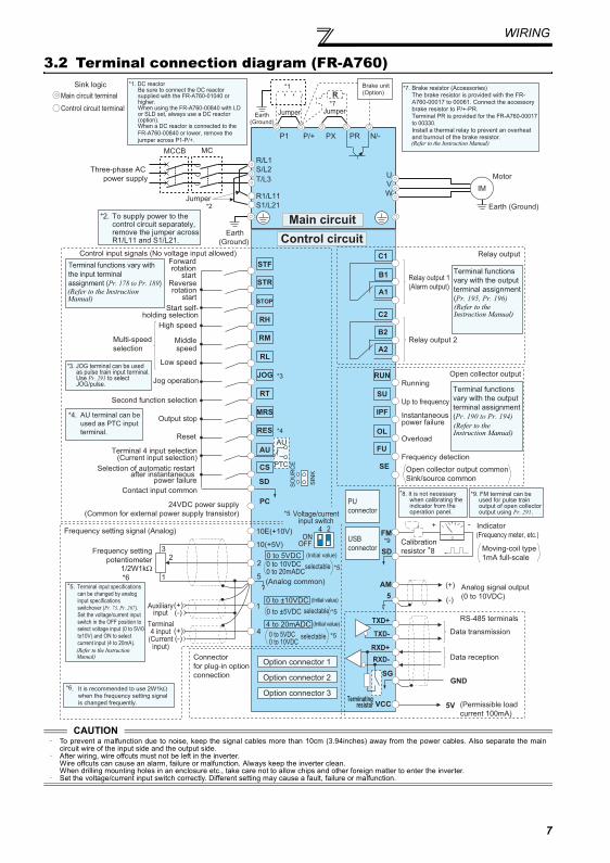
3.2 Terminal connection diagram (FR-A760)
CAUTION· To prevent a malfunction due to noise, keep the signal cables more than 10cm (3.94inches) away from the power cables. Also separate the main
circuit wire of the input side and the output side.· After wiring, wire offcuts must not be left in the inverter.
Wire offcuts can cause an alarm, failure or malfunction. Always keep the inverter clean.When drilling mounting holes in an enclosure etc., take care not to allow chips and other foreign matter to enter the inverter.
· Set the voltage/current input switch correctly. Different setting may cause a fault, failure or malfunction.
R/L1
S/L2
T/L3
R1/L11
S1/L21
PC
10E(+10V)
10(+5V)
2
(Analog common)
23
1
1
4
Jumper
C1
B1
A1
U
V
W
P1
0 to ±10VDC
*1
0 to 5VDC0 to 10VDC
MC
Main circuit
Control circuit
C2
B2
A2
IM
0 to 20mADC
AU
PTC
TXD+
TXD-
RXD+
RXD-
SGGND
SIN
K
SO
UR
CE
*4
*3
*5
STF
STR
STOP
RH
RM
RL
JOG
RT
MRS
RES
AU
CS
SD
RUN
SU
IPF
OL
FU
SE
(+)(-)
5
VCC
(+)(-)
5V
*2 Earth (Ground)
R
PX PR N/-P/+
*7
*3. JOG terminal can be usedas pulse train input terminal.Use Pr. 291 to selectJOG/pulse.
Main circuit terminal
Control circuit terminal
Three-phase AC
power supply
MCCB
Jumper
Earth
(Ground)
Earth(Ground)
selectable0 to ±5VDC *5
4 to 20mADC
0 to 5VDC0 to 10VDC
*5
Option connector 1
Option connector 2
Option connector 3
Connector
for plug-in option
connection
Frequency setting signal (Analog)
Frequency setting
potentiometer1/2W1kΩ
*6
Control input signals (No voltage input allowed)Forwardrotation
startReverserotation
start
Start self-holding selection
Terminal functions vary with
the input terminal
assignment (Pr. 178 to Pr. 189)
Middlespeed
High speed
Low speed
Multi-speed
selection
Jog operation
Second function selection
Output stop
Reset
Terminal 4 input selection(Current input selection)
Selection of automatic restart after instantaneous
power failure
USB
connector
PU
connector
Terminating resistor
Data reception
Data transmission
RS-485 terminals
Open collector output common
Sink/source common
Frequency detection
Running
Up to frequency
Instantaneous power failure
Overload
Terminal functions
vary with the output
terminal assignment
(Pr. 190 to Pr. 194)
Open collector output
(Permissible load
current 100mA)
Relay output 2
Relay output 1
(Alarm output)
Terminal functions
vary with the output
terminal assignment
(Pr. 195, Pr. 196)
Relay output
Motor
*4. AU terminal can be
used as PTC input
terminal.
*2. To supply power to the control circuit separately, remove the jumper across R1/L11 and S1/L21.
*8. It is not necessary when calibrating the indicator from the operation panel.
*6. It is recommended to use 2W1kΩ when the frequency setting signal is changed frequently.
(Initial value)
(Initial value)
(Initial value)
ON4 2
OFF
Voltage/current input switch
*5
Auxiliary input
Terminal 4 input
(Current input)
Brake unit(Option)
*5. Terminal input specifications can be changed by analog input specifications switchover (Pr. 73, Pr. 267). Set the voltage/current input switch in the OFF position to select voltage input (0 to 5V/0 to10V) and ON to select current input (4 to 20mA).
Sink logic*7. Brake resistor (Accessories)
The brake resistor is provided with the FR-A760-00017 to 00061. Connect the accessory brake resistor to P/+-PR.Terminal PR is provided for the FR-A760-00017 to 00330.Install a thermal relay to prevent an overheat and burnout of the brake resistor.
24VDC power supply
(Common for external power supply transistor)
Contact input common
FM
SD
+ -
AM
5
*9
*9. FM terminal can be used for pulse train output of open collector output using Pr. 291.
(+)
(-)(0 to 10VDC)
Analog signal output
Moving-coil type
1mA full-scale
(Frequency meter, etc.)
Indicator
Calibration
resistor *8
Jumper
selectable
selectable
*1. DC reactor Be sure to connect the DC reactor supplied with the FR-A760-01040 or higher. When using the FR-A760-00840 with LD or SLD set, always use a DC reactor (option). When a DC reactor is connected to the FR-A760-00840 or lower, remove the jumper across P1-P/+. (Refer to the Instruction Manual)
(Refer to the Instruction Manual)
(Refer to the Instruction Manual)
(Refer to the Instruction Manual)
(Refer to the Instruction Manual)
8
WIRING
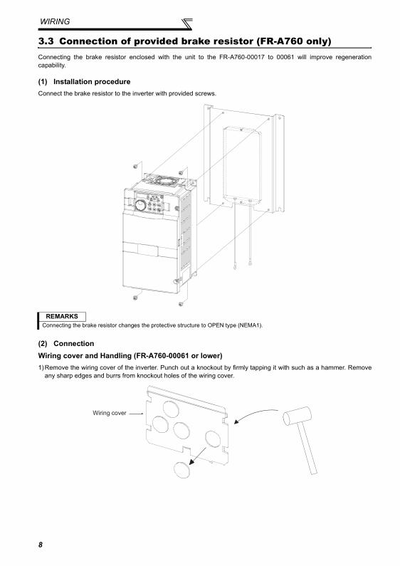
3.3 Connection of provided brake resistor (FR-A760 only)Connecting the brake resistor enclosed with the unit to the FR-A760-00017 to 00061 will improve regenerationcapability.
(1) Installation procedureConnect the brake resistor to the inverter with provided screws.
(2) ConnectionWiring cover and Handling (FR-A760-00061 or lower)1)Remove the wiring cover of the inverter. Punch out a knockout by firmly tapping it with such as a hammer. Remove
any sharp edges and burrs from knockout holes of the wiring cover.
REMARKSConnecting the brake resistor changes the protective structure to OPEN type (NEMA1).
Wiring cover
9
WIRING
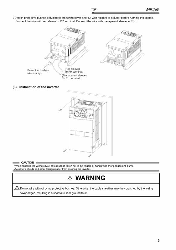
2)Attach protective bushes provided to the wiring cover and cut with nippers or a cutter before running the cables.Connect the wire with red sleeve to PR terminal. Connect the wire with transparent sleeve to P/+.
(3) Installation of the inverter
CAUTIONWhen handling the wiring cover, care must be taken not to cut fingers or hands with sharp edges and burrs.Avoid wire offcuts and other foreign matter from entering the inverter.
WARNINGDo not wire without using protective bushes. Otherwise, the cable sheathes may be scratched by the wiring cover edges, resulting in a short circuit or ground fault.
(Transparent sleeve)To P/+ terminal.
(Red sleeve)To PR terminal.
Protective bushes(Accessory)
WIRING
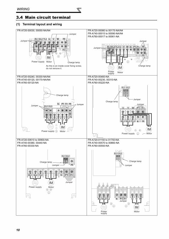
3.4 Main circuit terminal(1) Terminal layout and wiring
FR-A720-00030, 00050-NA/N4 FR-A720-00080 to 00175-NA/N4FR-A740-00015 to 00090-NA/N4FR-A760-00017 to 00061-NA
FR-A720-00240, 00330-NA/N4FR-A740-00120, 00170-NA/N4FR-A760-00120-NA
FR-A720-00460-NAFR-A740-00230, 00310-NAFR-A760-00220-NA
FR-A720-00610 to 00900-NAFR-A740-00380, 00440-NAFR-A760-00330-NA
FR-A720-01150 to 01750-NAFR-A740-00570 to 00860-NAFR-A760-00550-NA
R/L1 S/L2 T/L3
N/- P/+
PR
PXR1/L11 S1/L21
Charge lamp
As this is an inside cover fixing screw,
do not remove it.
Jumper
Jumper
MotorPower supply
IM
R/L1 S/L2 T/L3 N/- P/+ PR
PXR1/L11 S1/L21
IMCharge lamp
Jumper
Jumper
MotorPowersupply
R/L1 S/L2 T/L3
N/- P/+ PR
PX
R1/L11 S1/L21
IM
JumperJumper
Charge lamp
MotorPower supply
R1/L11 S1/L21
R/L1 S/L2 T/L3 N/-
P/+
PR
Charge lamp
Jumper
Jumper
Power supply
IMMotor
R/L1 S/L2 T/L3 N/- P/+
PR
R1/L11 S1/L21
IM
Jumper
Jumper
Charge lamp
MotorPower supply
R/L1 S/L2 T/L3 N/- P/+
R1/L11 S1/L21
IM
Jumper
Jumper
Charge lamp
MotorPowersupply
10
WIRING
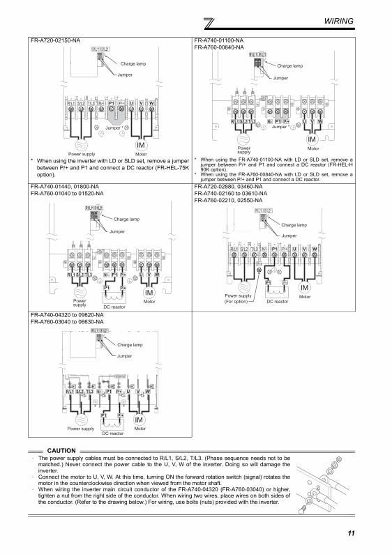
FR-A720-02150-NA
* When using the inverter with LD or SLD set, remove a jumperbetween P/+ and P1 and connect a DC reactor (FR-HEL-75Koption).
FR-A740-01100-NAFR-A760-00840-NA
* When using the FR-A740-01100-NA with LD or SLD set, remove ajumper between P/+ and P1 and connect a DC reactor (FR-HEL-H90K option).
* When using the FR-A760-00840-NA with LD or SLD set, remove ajumper between P/+ and P1 and connect a DC reactor.
FR-A740-01440, 01800-NAFR-A760-01040 to 01520-NA
FR-A720-02880, 03460-NAFR-A740-02160 to 03610-NAFR-A760-02210, 02550-NA
FR-A740-04320 to 09620-NAFR-A760-03040 to 06630-NA
CAUTION· The power supply cables must be connected to R/L1, S/L2, T/L3. (Phase sequence needs not to be
matched.) Never connect the power cable to the U, V, W of the inverter. Doing so will damage theinverter.
· Connect the motor to U, V, W. At this time, turning ON the forward rotation switch (signal) rotates themotor in the counterclockwise direction when viewed from the motor shaft.
· When wiring the inverter main circuit conductor of the FR-A740-04320 (FR-A760-03040) or higher,tighten a nut from the right side of the conductor. When wiring two wires, place wires on both sides ofthe conductor. (Refer to the drawing below.) For wiring, use bolts (nuts) provided with the inverter.
Power supply
IMMotor
R/L1 S/L2 T/L3 N/-
Jumper
Jumper *
Charge lamp
R1/L11 S1/L21
P/+
IM
Jumper
Charge lamp
Powersupply
Motor
R/L1 S/L2 T/L3 N/-
R1/L11 S1/L21
Jumper *P/+
IM
R/L1 S/L2 T/L3 N/- P/+
R1/L11 S1/L21
DC reactor
Powersupply
Motor
Jumper
Charge lamp
P/+
R/L1 S/L2 T/L3 N/-
P/+
R1/L11 S1/L21
P/+
P/+
IM
Jumper
Charge lamp
MotorPower supply
(For option) DC reactor
IM
R/L1 S/L2 T/L3 N/-
R1/L11 S1/L21
P/+
P/+
Jumper
Charge lamp
MotorPower supplyDC reactor
11
WIRING
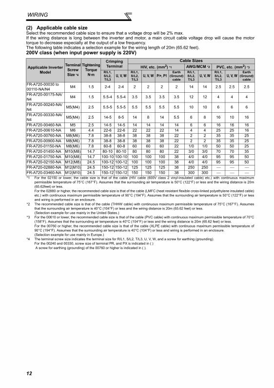
(2) Applicable cable sizeSelect the recommended cable size to ensure that a voltage drop will be 2% max.If the wiring distance is long between the inverter and motor, a main circuit cable voltage drop will cause the motortorque to decrease especially at the output of a low frequency.The following table indicates a selection example for the wiring length of 20m (65.62 feet).200V class (when input power supply is 220V)
Applicable Inverter Model
Terminal Screw Size *4
Tightening Torque
N·m
Crimping Terminal
Cable SizesHIV, etc. (mm2) *1 AWG/MCM *2 PVC, etc. (mm2) *3
R/L1, S/L2, T/L3
U, V, WR/L1, S/L2, T/L3
U, V, W P/+, P1Earth
(Ground)cable
R/L1, S/L2, T/L3
U, V, WR/L1, S/L2, T/L3
U, V, WEarth
(Ground)cable
FR-A720-00030 to 00110-NA/N4 M4 1.5 2-4 2-4 2 2 2 2 14 14 2.5 2.5 2.5
FR-A720-00175-NA/N4 M4 1.5 5.5-4 5.5-4 3.5 3.5 3.5 3.5 12 12 4 4 4
FR-A720-00240-NA/N4 M5(M4) 2.5 5.5-5 5.5-5 5.5 5.5 5.5 5.5 10 10 6 6 6
FR-A720-00330-NA/N4 M5(M4) 2.5 14-5 8-5 14 8 14 5.5 6 8 16 10 16
FR-A720-00460-NA M5 2.5 14-5 14-5 14 14 14 14 6 6 16 16 16FR-A720-00610-NA M6 4.4 22-6 22-6 22 22 22 14 4 4 25 25 16FR-A720-00760-NA M8(M6) 7.8 38-8 38-8 38 38 38 22 2 2 35 35 25FR-A720-00900-NA M8(M6) 7.8 38-8 38-8 38 38 38 22 2 2 35 35 25FR-A720-01150-NA M8(M6) 7.8 60-8 60-8 60 60 60 22 1/0 1/0 50 50 25FR-A720-01450-NA M10(M8) 14.7 80-10 80-10 80 80 80 22 3/0 3/0 70 70 35FR-A720-01750-NA M10(M8) 14.7 100-10 100-10 100 100 100 38 4/0 4/0 95 95 50FR-A720-02150-NA M12(M8) 24.5 100-12 100-12 100 100 100 38 4/0 4/0 95 95 50FR-A720-02880-NA M12(M10) 24.5 150-12 150-12 125 125 125 38 250 250 ⎯ ⎯ ⎯FR-A720-03460-NA M12(M10) 24.5 150-12 150-12 150 150 150 38 300 300 ⎯ ⎯ ⎯*1 For the 02150 or lower, the cable size is that of the cable (HIV cable (600V class 2 vinyl-insulated cable) etc.) with continuous maximum
permissible temperature of 75°C (167°F). Assumes that the surrounding air temperature is 50°C (122°F) or less and the wiring distance is 20m(65.62feet) or less.For the 02880 or higher, the recommended cable size is that of the cable (LMFC (heat resistant flexible cross-linked polyethylene insulated cable)etc.) with continuous maximum permissible temperature of 90°C (194°F). Assumes that the surrounding air temperature is 50°C (122°F) or lessand wiring is performed in an enclosure.
*2 The recommended cable size is that of the cable (THHW cable) with continuous maximum permissible temperature of 75°C (167°F). Assumesthat the surrounding air temperature is 40°C (104°F) or less and the wiring distance is 20m (65.62 feet) or less. (Selection example for use mainly in the United States.)
*3 For the 00610 or lower, the recommended cable size is that of the cable (PVC cable) with continuous maximum permissible temperature of 70°C(158°F). Assumes that the surrounding air temperature is 40°C (104°F) or less and the wiring distance is 20m (65.62 feet) or less.For the 00760 or higher, the recommended cable size is that of the cable (XLPE cable) with continuous maximum permissible temperature of90°C (194°F). Assumes that the surrounding air temperature is 40°C (104°F) or less and wiring is performed in an enclosure. (Selection example for use mainly in Europe.)
*4 The terminal screw size indicates the terminal size for R/L1, S/L2, T/L3, U, V, W, and a screw for earthing (grounding).For the 00240 and 00330, screw size of terminal PR, and PX is indicated in ( ) A screw for earthing (grounding) of the 00760 or higher is indicated in ( ).
12
WIRING
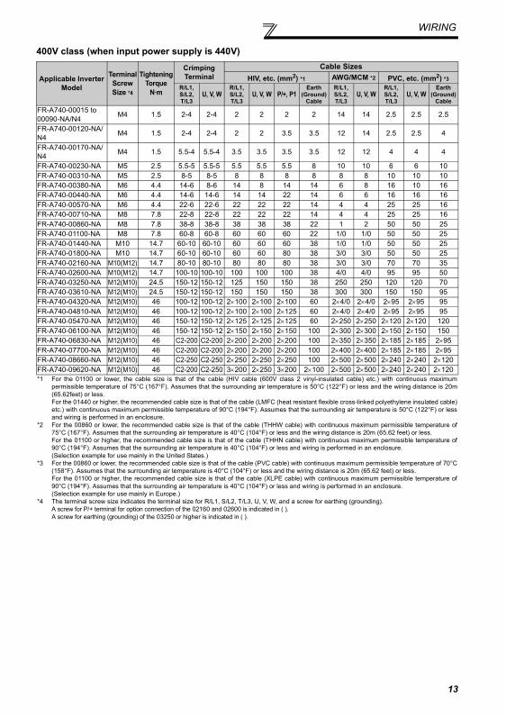
400V class (when input power supply is 440V)
Applicable Inverter Model
Terminal Screw Size *4
Tightening Torque
N·m
Crimping Terminal
Cable SizesHIV, etc. (mm2) *1 AWG/MCM *2 PVC, etc. (mm2) *3
R/L1, S/L2, T/L3
U, V, WR/L1, S/L2, T/L3
U, V, W P/+, P1Earth
(Ground)Cable
R/L1, S/L2, T/L3
U, V, WR/L1, S/L2, T/L3
U, V, WEarth
(Ground)Cable
FR-A740-00015 to 00090-NA/N4 M4 1.5 2-4 2-4 2 2 2 2 14 14 2.5 2.5 2.5
FR-A740-00120-NA/N4 M4 1.5 2-4 2-4 2 2 3.5 3.5 12 14 2.5 2.5 4
FR-A740-00170-NA/N4 M4 1.5 5.5-4 5.5-4 3.5 3.5 3.5 3.5 12 12 4 4 4
FR-A740-00230-NA M5 2.5 5.5-5 5.5-5 5.5 5.5 5.5 8 10 10 6 6 10FR-A740-00310-NA M5 2.5 8-5 8-5 8 8 8 8 8 8 10 10 10FR-A740-00380-NA M6 4.4 14-6 8-6 14 8 14 14 6 8 16 10 16FR-A740-00440-NA M6 4.4 14-6 14-6 14 14 22 14 6 6 16 16 16FR-A740-00570-NA M6 4.4 22-6 22-6 22 22 22 14 4 4 25 25 16FR-A740-00710-NA M8 7.8 22-8 22-8 22 22 22 14 4 4 25 25 16FR-A740-00860-NA M8 7.8 38-8 38-8 38 38 38 22 1 2 50 50 25FR-A740-01100-NA M8 7.8 60-8 60-8 60 60 60 22 1/0 1/0 50 50 25FR-A740-01440-NA M10 14.7 60-10 60-10 60 60 60 38 1/0 1/0 50 50 25FR-A740-01800-NA M10 14.7 60-10 60-10 60 60 80 38 3/0 3/0 50 50 25FR-A740-02160-NA M10(M12) 14.7 80-10 80-10 80 80 80 38 3/0 3/0 70 70 35FR-A740-02600-NA M10(M12) 14.7 100-10 100-10 100 100 100 38 4/0 4/0 95 95 50FR-A740-03250-NA M12(M10) 24.5 150-12 150-12 125 150 150 38 250 250 120 120 70FR-A740-03610-NA M12(M10) 24.5 150-12 150-12 150 150 150 38 300 300 150 150 95FR-A740-04320-NA M12(M10) 46 100-12 100-12 2×100 2×100 2×100 60 2×4/0 2×4/0 2×95 2×95 95FR-A740-04810-NA M12(M10) 46 100-12 100-12 2×100 2×100 2×125 60 2×4/0 2×4/0 2×95 2×95 95FR-A740-05470-NA M12(M10) 46 150-12 150-12 2×125 2×125 2×125 60 2×250 2×250 2×120 2×120 120FR-A740-06100-NA M12(M10) 46 150-12 150-12 2×150 2×150 2×150 100 2×300 2×300 2×150 2×150 150FR-A740-06830-NA M12(M10) 46 C2-200 C2-200 2×200 2×200 2×200 100 2×350 2×350 2×185 2×185 2×95FR-A740-07700-NA M12(M10) 46 C2-200 C2-200 2×200 2×200 2×200 100 2×400 2×400 2×185 2×185 2×95FR-A740-08660-NA M12(M10) 46 C2-250 C2-250 2×250 2×250 2×250 100 2×500 2×500 2×240 2×240 2×120FR-A740-09620-NA M12(M10) 46 C2-200 C2-250 3×200 2×250 3×200 2×100 2×500 2×500 2×240 2×240 2×120*1 For the 01100 or lower, the cable size is that of the cable (HIV cable (600V class 2 vinyl-insulated cable) etc.) with continuous maximum
permissible temperature of 75°C (167°F). Assumes that the surrounding air temperature is 50°C (122°F) or less and the wiring distance is 20m(65.62feet) or less.For the 01440 or higher, the recommended cable size is that of the cable (LMFC (heat resistant flexible cross-linked polyethylene insulated cable)etc.) with continuous maximum permissible temperature of 90°C (194°F). Assumes that the surrounding air temperature is 50°C (122°F) or lessand wiring is performed in an enclosure.
*2 For the 00860 or lower, the recommended cable size is that of the cable (THHW cable) with continuous maximum permissible temperature of75°C (167°F). Assumes that the surrounding air temperature is 40°C (104°F) or less and the wiring distance is 20m (65.62 feet) or less.For the 01100 or higher, the recommended cable size is that of the cable (THHN cable) with continuous maximum permissible temperature of90°C (194°F). Assumes that the surrounding air temperature is 40°C (104°F) or less and wiring is performed in an enclosure.(Selection example for use mainly in the United States.)
*3 For the 00860 or lower, the recommended cable size is that of the cable (PVC cable) with continuous maximum permissible temperature of 70°C(158°F). Assumes that the surrounding air temperature is 40°C (104°F) or less and the wiring distance is 20m (65.62 feet) or less.For the 01100 or higher, the recommended cable size is that of the cable (XLPE cable) with continuous maximum permissible temperature of90°C (194°F). Assumes that the surrounding air temperature is 40°C (104°F) or less and wiring is performed in an enclosure.(Selection example for use mainly in Europe.)
*4 The terminal screw size indicates the terminal size for R/L1, S/L2, T/L3, U, V, W, and a screw for earthing (grounding).A screw for P/+ terminal for option connection of the 02160 and 02600 is indicated in ( ).A screw for earthing (grounding) of the 03250 or higher is indicated in ( ).
13
WIRING
)
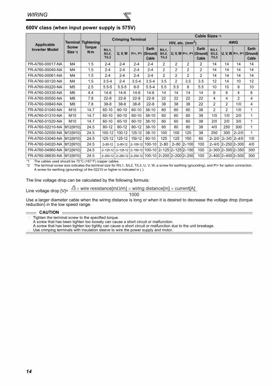
600V class (when input power supply is 575V)
The line voltage drop can be calculated by the following formula:
Line voltage drop [V]=
Use a larger diameter cable when the wiring distance is long or when it is desired to decrease the voltage drop (torquereduction) in the low speed range.
ApplicableInverter Model
Terminal Screw Size *2
Tightening Torque
N·m
Crimping TerminalCable Sizes *1
HIV, etc. (mm2) AWG
R/L1, S/L2, T/L3
U, V, W P/+, P1Earth
(Ground)Cable
R/L1, S/L2, T/L3
U, V, W P/+, P1Earth
(Ground)Cable
R/L1, S/L2, T/L3
U, V, W P/+, P1Earth
(GroundCable
FR-A760-00017-NA M4 1.5 2-4 2-4 2-4 2-4 2 2 2 2 14 14 14 14FR-A760-00040-NA M4 1.5 2-4 2-4 2-4 2-4 2 2 2 2 14 14 14 14FR-A760-00061-NA M4 1.5 2-4 2-4 2-4 2-4 2 2 2 2 14 14 14 14FR-A760-00120-NA M4 1.5 3.5-4 2-4 3.5-4 3.5-4 3.5 2 3.5 3.5 12 14 10 12FR-A760-00220-NA M5 2.5 5.5-5 5.5-5 8-5 5.5-4 5.5 5.5 8 5.5 10 10 8 10FR-A760-00330-NA M6 4.4 14-6 14-6 14-6 14-6 14 14 14 14 6 6 4 6FR-A760-00550-NA M8 7.8 22-8 22-8 22-8 22-8 22 22 22 22 4 4 2 4FR-A760-00840-NA M8 7.8 38-8 38-8 38-8 22-8 38 38 38 22 2 2 1/0 4FR-A760-01040-NA M10 14.7 60-10 60-10 60-10 38-10 60 60 60 38 2 2 1/0 1FR-A760-01310-NA M10 14.7 60-10 60-10 60-10 38-10 60 60 60 38 1/0 1/0 2/0 1FR-A760-01520-NA M10 14.7 60-10 60-10 60-10 38-10 60 60 60 38 2/0 2/0 3/0 1FR-A760-02210-NA M12(M10) 24.5 80-12 80-12 80-12 38-10 80 80 80 38 4/0 250 300 1FR-A760-02550-NA M12(M10) 24.5 100-12 100-12 125-12 38-10 100 100 125 38 250 300 2×2/0 1FR-A760-03040-NA M12(M10) 24.5 125-12 125-12 150-12 60-10 125 125 150 60 2×2/0 2×3/0 2×4/0 1/0FR-A760-04020-NA M12(M10) 24.5 2×80-12 2×80-12 2×100-12 100-10 2×80 2×80 2×100 100 2×4/0 2×250 2×300 4/0FR-A760-04960-NA M12(M10) 24.5 2×125-12 2×125-12 2×150-12 100-10 2×125 2×125 2×150 100 2×300 2×300 2×350 300FR-A760-06630-NA M12(M10) 24.5 2×200-12 2×200-12 2×250-12 100-10 2×200 2×200 2×250 100 2×400 2×400 2×500 300
*1 The cables used should be 75°C (167°F) copper cables.*2 The terminal screw size indicates the terminal size for R/L1, S/L2, T/L3, U, V, W, a screw for earthing (grounding), and P/+ for option connection.
A screw for earthing (grounding) of the 02210 or higher is indicated in ( ).
CAUTION· Tighten the terminal screw to the specified torque.
A screw that has been tighten too loosely can cause a short circuit or malfunction.A screw that has been tighten too tightly can cause a short circuit or malfunction due to the unit breakage.
· Use crimping terminals with insulation sleeve to wire the power supply and motor.
3 × wire resistance[mΩ/m] × wiring distance[m] × current[A]
1000
14
WIRING
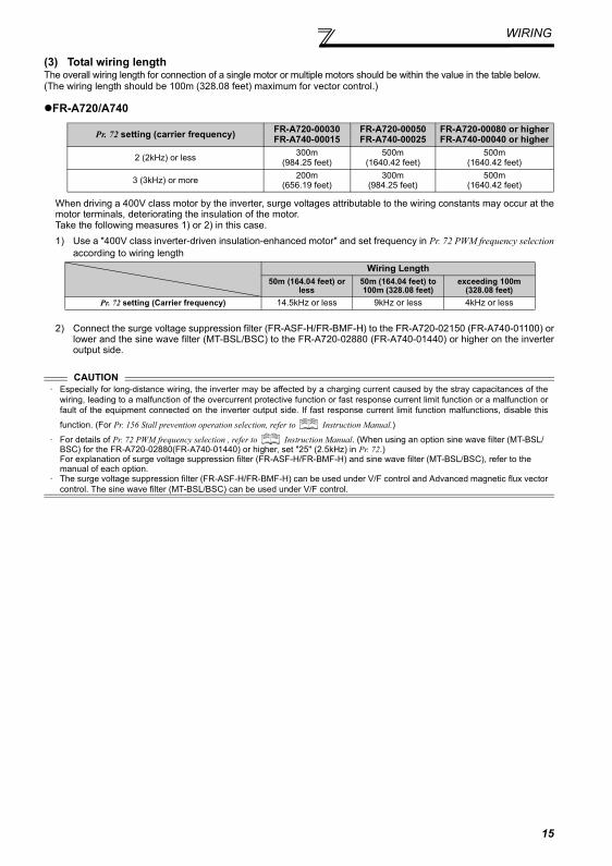
(3) Total wiring lengthThe overall wiring length for connection of a single motor or multiple motors should be within the value in the table below. (The wiring length should be 100m (328.08 feet) maximum for vector control.)
FR-A720/A740
When driving a 400V class motor by the inverter, surge voltages attributable to the wiring constants may occur at themotor terminals, deteriorating the insulation of the motor.Take the following measures 1) or 2) in this case.1) Use a "400V class inverter-driven insulation-enhanced motor" and set frequency in Pr. 72 PWM frequency selection
according to wiring length
2) Connect the surge voltage suppression filter (FR-ASF-H/FR-BMF-H) to the FR-A720-02150 (FR-A740-01100) orlower and the sine wave filter (MT-BSL/BSC) to the FR-A720-02880 (FR-A740-01440) or higher on the inverteroutput side.
Pr. 72 setting (carrier frequency) FR-A720-00030FR-A740-00015
FR-A720-00050FR-A740-00025
FR-A720-00080 or higherFR-A740-00040 or higher
2 (2kHz) or less 300m(984.25 feet)
500m(1640.42 feet)
500m(1640.42 feet)
3 (3kHz) or more 200m(656.19 feet)
300m(984.25 feet)
500m(1640.42 feet)
CAUTION· Especially for long-distance wiring, the inverter may be affected by a charging current caused by the stray capacitances of the
wiring, leading to a malfunction of the overcurrent protective function or fast response current limit function or a malfunction orfault of the equipment connected on the inverter output side. If fast response current limit function malfunctions, disable this
function. (For Pr. 156 Stall prevention operation selection, refer to Instruction Manual.)
· For details of Pr. 72 PWM frequency selection , refer to Instruction Manual. (When using an option sine wave filter (MT-BSL/BSC) for the FR-A720-02880(FR-A740-01440) or higher, set "25" (2.5kHz) in Pr. 72.)For explanation of surge voltage suppression filter (FR-ASF-H/FR-BMF-H) and sine wave filter (MT-BSL/BSC), refer to the manual of each option.
· The surge voltage suppression filter (FR-ASF-H/FR-BMF-H) can be used under V/F control and Advanced magnetic flux vectorcontrol. The sine wave filter (MT-BSL/BSC) can be used under V/F control.
Wiring Length50m (164.04 feet) or
less50m (164.04 feet) to 100m (328.08 feet)
exceeding 100m (328.08 feet)
Pr. 72 setting (Carrier frequency) 14.5kHz or less 9kHz or less 4kHz or less
15
WIRING
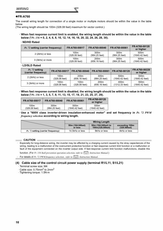
FR-A760The overall wiring length for connection of a single motor or multiple motors should be within the value in the tablebelow.(The wiring length should be 100m (328.08 feet) maximum for vector control.)
· When fast response current limit is enabled, the wiring length should be within the value in the tablebelow (*Pr. 156 = 0, 2, 4, 6, 8, 10, 12, 14, 16, 18, 20, 22, 24, 26, 28, 30).· ND/HD Rated
· LD/SLD Rated
· When fast response current limit is disabled, the wiring length should be within the value in the tablebelow (*Pr. 156 = 1, 3, 5, 7, 9, 11, 13, 15, 17, 19, 21, 23, 25, 27, 29).
· Use a "600V class inverter-driven insulation-enhanced motor" and set frequency in Pr. 72 PWMfrequency selection according to wiring length.
(4) Cable size of the control circuit power supply (terminal R1/L11, S1/L21)· Terminal screw size: M4· Cable size: 0.75mm2 to 2mm2
· Tightening torque: 1.5N·m
Pr. 72 setting (carrier frequency) FR-A760-00017 FR-A760-00040 FR-A760-00061 FR-A760-00120or higher
2 (2kHz) or less 100m(328.08 feet)
300m(984.25 feet)
300m(984.25 feet)
500m(1640.42 feet)
3 (3kHz) or more 100m(328.08 feet)
200m(656.16 feet)
300m(984.25 feet)
500m(1640.42 feet)
Pr. 72 setting (carrier frequency) FR-A760-00017 FR-A760-00040 FR-A760-00061 FR-A760-00120 FR-A760-00220
or higher
2 (2kHz) or less 100m(328.08 feet)
200m(656.16 feet)
300m(984.25 feet)
500m(1640.42 feet)
500m(1640.42 feet)
3 (3kHz) or more 100m(328.08 feet)
100m(328.08 feet)
200m(656.16 feet)
400m(1312.33 feet)
500m(1640.42 feet)
FR-A760-00017 FR-A760-00040 FR-A760-00061 FR-A760-00120or higher
100m(328.08 feet)
300m(984.25 feet)
500m(1640.42 feet)
500m(1640.42 feet)
Wiring Length50m (164.04feet)
or less50m (164.04feet) to 100m(328.08feet)
exceeding 100m (328.08feet)
Pr. 72 setting (carrier frequency) 14.5kHz or less 9kHz or less 4kHz or less
CAUTION· Especially for long-distance wiring, the inverter may be affected by a charging current caused by the stray capacitances of the
wiring, leading to a malfunction of the overcurrent protective function or fast response current limit function or a malfunction orfault of the equipment connected on the inverter output side. If fast-response current limit function malfunctions, disable this
function. (For Pr. 156 Stall prevention operation selection, refer to Instruction Manual.)
· For details of Pr. 72 PWM frequency selection , refer to Instruction Manual.
16
WIRING
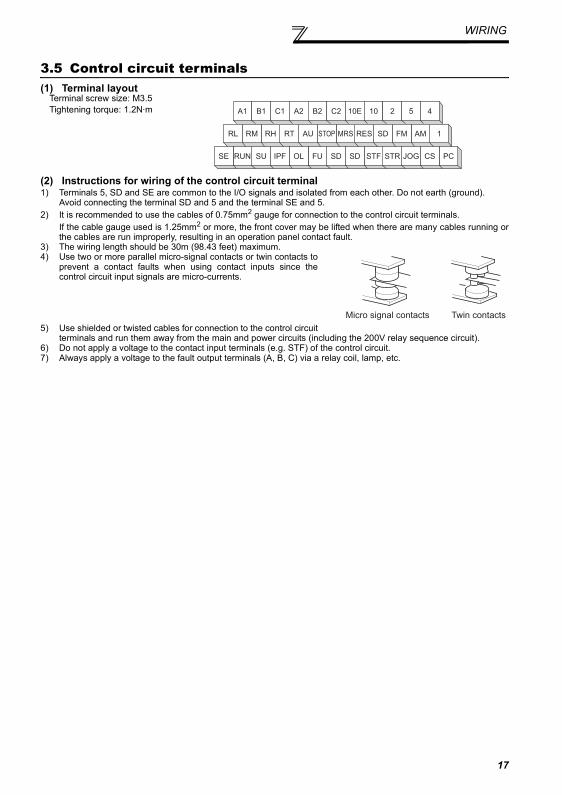
3.5 Control circuit terminals(1) Terminal layout
(2) Instructions for wiring of the control circuit terminal1) Terminals 5, SD and SE are common to the I/O signals and isolated from each other. Do not earth (ground).
Avoid connecting the terminal SD and 5 and the terminal SE and 5.2) It is recommended to use the cables of 0.75mm2 gauge for connection to the control circuit terminals.
If the cable gauge used is 1.25mm2 or more, the front cover may be lifted when there are many cables running orthe cables are run improperly, resulting in an operation panel contact fault.
3) The wiring length should be 30m (98.43 feet) maximum.4) Use two or more parallel micro-signal contacts or twin contacts to
prevent a contact faults when using contact inputs since thecontrol circuit input signals are micro-currents.
5) Use shielded or twisted cables for connection to the control circuitterminals and run them away from the main and power circuits (including the 200V relay sequence circuit).
6) Do not apply a voltage to the contact input terminals (e.g. STF) of the control circuit.7) Always apply a voltage to the fault output terminals (A, B, C) via a relay coil, lamp, etc.
Terminal screw size: M3.5Tightening torque: 1.2N·m A1 B1 C1 A2 B2 C2 10E 10 2 5 4
1AMSDRESMRSSTOPAURTRHRMRL
PCCSJOGSTRSTFSDSDFUOLIPFSURUNSE
FM
Micro signal contacts Twin contacts
17
PRECAUTIONS FOR USE OF THE INVERTER
4 PRECAUTIONS FOR USE OF THE INVERTER
The FR-A700 series is a highly reliable product, but incorrect peripheral circuit making or operation/handling methodmay shorten the product life or damage the product.Before starting operation, always recheck the following items.
(1) Use crimping terminals with insulation sleeve to wire the power supply and motor.
(2) Application of power to the output terminals (U, V, W) of the inverter will damage the inverter. Never performsuch wiring.
(3) After wiring, wire offcuts must not be left in the inverter.Wire offcuts can cause an alarm, failure or malfunction. Always keep the inverter clean. When drilling mounting holes inan enclosure etc., take care not to allow chips and other foreign matter to enter the inverter.
(4) Use cables of the size to make a voltage drop 2% maximum.If the wiring distance is long between the inverter and motor, a main circuit cable voltage drop will cause the motor torqueto decrease especially at the output of a low frequency.Refer to page 12 for the recommended cable sizes.
(5) The overall wiring length should be 500m (1640.4 feet) maximum.(The wiring length should be 100m (328.1 feet) maximum for vector control.)Especially for long distance wiring, the fast response current limit function may decrease or the equipment connected tothe secondary side may malfunction or become faulty under the influence of a charging current due to the stray capacityof the wiring. Therefore, note the overall wiring length. (Refer to page 15.)
(6) Electromagnetic wave interferenceThe input/output (main circuit) of the inverter includes high frequency components, which may interfere with thecommunication devices (such as AM radios) used near the inverter. In this case, set the EMC filter valid to minimizeinterference. (Only the FR-A720/A740 are provided with an EMC filter.)
(7) Do not install a power factor correction capacitor, surge suppressor or radio noise filter on the inverter outputside.This will cause the inverter to trip or the capacitor, and surge suppressor to be damaged. If any of the above devices isinstalled, immediately remove it.
(8) For some short time after the power is switched OFF, a high voltage remains in the smoothing capacitor. When accessing the inverter for inspection, wait for at least 10 minutes after the power supply has been switched OFF,and then make sure that the voltage across the main circuit terminals P/+-N/- of the inverter is not more than 30VDCusing a tester, etc. The capacitor is charged with high voltage for some time after power off and it is dangerous.
(9) A short circuit or earth (ground) fault on the inverter output side may damage the inverter modules.· Fully check the insulation resistance of the circuit prior to inverter operation since repeated short circuits caused by
peripheral circuit inadequacy or an earth (ground) fault caused by wiring inadequacy or reduced motor insulationresistance may damage the inverter modules.
· Fully check the to-earth (ground) insulation and phase to phase insulation of the inverter output side before power-on.Especially for an old motor or use in hostile atmosphere, securely check the motor insulation resistance etc.
(10) Do not use the inverter input side magnetic contactor to start/stop the inverter.Since repeated inrush currents at power ON will shorten the life of the converter circuit (switching life is about1,000,000 times (for the 200V class FR-A720-01450 or higher, switching life is about 500,000)), frequent startsand stops of the MC must be avoided. Always use the start signal (ON/OFF of STF and STR signals) to start/stopthe inverter.
(11) Across P/+ and PR terminals, connect only an external regenerative brake discharge resistor.Do not connect a mechanical brake.
(12) Do not apply a voltage higher than the permissible voltage to the inverter I/O signal circuits.Application of permissible voltage to the inverter I/O signal circuit and incorrect polarity may damage the I/O terminal.Especially check the wiring to prevent the speed setting potentiometer from being connected incorrectly to shortterminals 10E-5.
18
PRECAUTIONS FOR USE OFTHE INVERTER
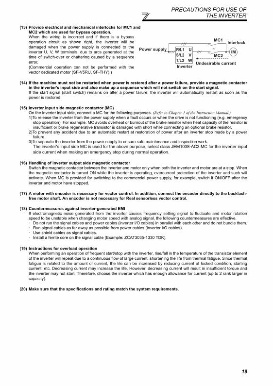
(13) Provide electrical and mechanical interlocks for MC1 and MC2 which are used for bypass operation.When the wiring is incorrect and if there is a bypassoperation circuit as shown right, the inverter will bedamaged when the power supply is connected to theinverter U, V, W terminals, due to arcs generated at thetime of switch-over or chattering caused by a sequenceerror.(Commercial operation can not be performed with thevector dedicated motor (SF-V5RU, SF-THY).)
(14) If the machine must not be restarted when power is restored after a power failure, provide a magnetic contactorin the inverter's input side and also make up a sequence which will not switch on the start signal.If the start signal (start switch) remains on after a power failure, the inverter will automatically restart as soon as thepower is restored.
(15) Inverter input side magnetic contactor (MC)On the inverter input side, connect a MC for the following purposes. (Refer to Chapter 1 of the Instruction Manual.)1)To release the inverter from the power supply when a fault occurs or when the drive is not functioning (e.g. emergency
stop operation). For example, MC avoids overheat or burnout of the brake resistor when heat capacity of the resistor isinsufficient or brake regenerative transistor is damaged with short while connecting an optional brake resistor.
2)To prevent any accident due to an automatic restart at restoration of power after an inverter stop made by a powerfailure
3)To separate the inverter from the power supply to ensure safe maintenance and inspection work.The inverter's input side MC is used for the above purpose, select class JEM1038-AC3 MC for the inverter inputside current when making an emergency stop during normal operation.
(16) Handling of inverter output side magnetic contactorSwitch the magnetic contactor between the inverter and motor only when both the inverter and motor are at a stop. Whenthe magnetic contactor is turned ON while the inverter is operating, overcurrent protection of the inverter and such willactivate. When MC is provided for switching to the commercial power supply, for example, switch it ON/OFF after theinverter and motor have stopped.
(17) A motor with encoder is necessary for vector control. In addition, connect the encoder directly to the backlash-free motor shaft. An encoder is not necessary for Real sensorless vector control.
(18) Countermeasures against inverter-generated EMIIf electromagnetic noise generated from the inverter causes frequency setting signal to fluctuate and motor rotationspeed to be unstable when changing motor speed with analog signal, the following countermeasures are effective.· Do not run the signal cables and power cables (inverter I/O cables) in parallel with each other and do not bundle them.· Run signal cables as far away as possible from power cables (inverter I/O cables).· Use shield cables as signal cables.· Install a ferrite core on the signal cable (Example: ZCAT3035-1330 TDK).
(19) Instructions for overload operationWhen performing an operation of frequent start/stop with the inverter, rise/fall in the temperature of the transistor elementof the inverter will repeat due to a continuous flow of large current, shortening the life from thermal fatigue. Since thermalfatigue is related to the amount of current, the life can be increased by reducing current at locked condition, startingcurrent, etc. Decreasing current may increase the life. However, decreasing current will result in insufficient torque andthe inverter may not start. Therefore, choose the inverter which has enough allowance for current (up to 2 rank larger incapacity).
(20) Make sure that the specifications and rating match the system requirements.
MC2
MC1
U
V
W
R/L1
S/L2
T/L3
IMPower supply
InverterUndesirable current
Interlock
19
20
FAILSAFE OF THE SYSTEM WHICH USES THE INVERTER
5 FAILSAFE OF THE SYSTEM WHICH USES THE INVERTER
When a fault occurs, the inverter trips to output a fault signal. However, a fault output signal may not be output at aninverter fault occurrence when the detection circuit or output circuit fails, etc. Although Mitsubishi assures best qualityproducts, provide an interlock which uses inverter status output signals to prevent accidents such as damage tomachine when the inverter fails for some reason and at the same time consider the system configuration where failsafefrom outside the inverter, without using the inverter, is enabled even if the inverter fails.
(1) Interlock method which uses the inverter status output signals By combining the inverter status output signals to provide an interlock as shown below, an inverter alarm can bedetected.
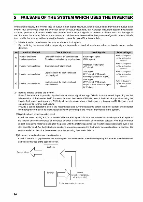
(2) Backup method outside the inverterEven if the interlock is provided by the inverter status signal, enough failsafe is not ensured depending on thefailure status of the inverter itself. For example, when the inverter CPU fails, even if the interlock is provided using theinverter fault signal, start signal and RUN signal, there is a case where a fault signal is not output and RUN signal is keptoutput even if an inverter fault occurs.Provide a speed detector to detect the motor speed and current detector to detect the motor current and considerthe backup system such as checking up as below according to the level of importance of the system.
1) Start signal and actual operation checkCheck the motor running and motor current while the start signal is input to the inverter by comparing the start signal tothe inverter and detected speed of the speed detector or detected current of the current detector. Note that the motorcurrent runs as the motor is running for the period until the motor stops since the inverter starts decelerating even if thestart signal turns off. For the logic check, configure a sequence considering the inverter deceleration time. In addition, it isrecommended to check the three-phase current when using the current detector.
2) Command speed and actual operation checkCheck if there is no gap between the actual speed and commanded speed by comparing the inverter speed commandand detected speed of the speed detector.
No Interlock Method Check Method Used Signals Refer to Page
1) Inverter protective function operation
Operation check of an alarm contactCircuit error detection by negative logic
Fault output signal (ALM signal)
Refer to Chapter 4 of the Instruction
Manual.
2) Inverter running status Operation ready signal check Operation ready signal (RY signal)
Refer to Chapter 4 of the Instruction
Manual.
3) Inverter running status Logic check of the start signal and running signal
Start signal (STF signal, STR signal)Running signal (RUN signal)
Refer to Chapter 4 of the Instruction
Manual.
4) Inverter running status Logic check of the start signal and output current
Start signal (STF signal, STR signal)Output current detection signal (Y12 signal)
Refer to Chapter 4 of the Instruction
Manual.
Inverter
Controller
System failure
To the alarm detection sensor
Sensor
(speed, temperature,
air volume, etc.)
PARAMETER LIST
6 PARAMETER LIST
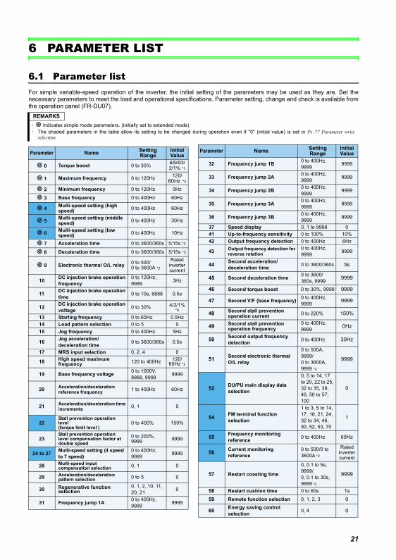
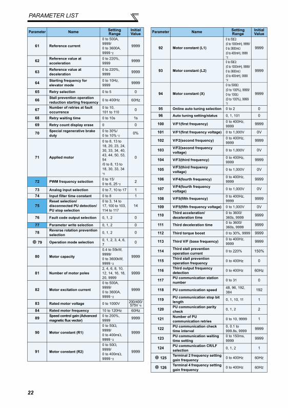
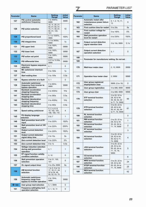
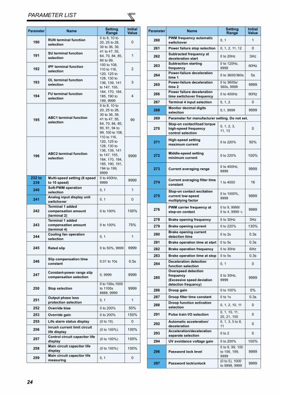
6.1 Parameter listFor simple variable-speed operation of the inverter, the initial setting of the parameters may be used as they are. Set thenecessary parameters to meet the load and operational specifications. Parameter setting, change and check is available fromthe operation panel (FR-DU07).
REMARKS⋅ indicates simple mode parameters. (initially set to extended mode)⋅ The shaded parameters in the table allow its setting to be changed during operation even if "0" (initial value) is set in Pr. 77 Parameter write
selection.
Parameter Name Setting Range
Initial Value
0 Torque boost 0 to 30% 6/5/4/3/2/1% *1
1 Maximum frequency 0 to 120Hz 120/60Hz *2
2 Minimum frequency 0 to 120Hz 0Hz
3 Base frequency 0 to 400Hz 60Hz
4 Multi-speed setting (high speed) 0 to 400Hz 60Hz
5 Multi-speed setting (middle speed) 0 to 400Hz 30Hz
6 Multi-speed setting (low speed) 0 to 400Hz 10Hz
7 Acceleration time 0 to 3600/360s 5/15s *3
8 Deceleration time 0 to 3600/360s 5/15s *3
9 Electronic thermal O/L relay 0 to 500/0 to 3600A *2
Rated inverter current
10 DC injection brake operation frequency
0 to 120Hz, 9999 3Hz
11 DC injection brake operation time 0 to 10s, 8888 0.5s
12 DC injection brake operation voltage 0 to 30% 4/2/1%
*4
13 Starting frequency 0 to 60Hz 0.5Hz14 Load pattern selection 0 to 5 015 Jog frequency 0 to 400Hz 5Hz
16 Jog acceleration/deceleration time 0 to 3600/360s 0.5s
17 MRS input selection 0, 2, 4 0
18 High speed maximum frequency 120 to 400Hz 120/
60Hz *2
19 Base frequency voltage 0 to 1000V, 8888, 9999 9999
20 Acceleration/deceleration reference frequency 1 to 400Hz 60Hz
21 Acceleration/deceleration time increments 0, 1 0
22Stall prevention operation level(torque limit level )
0 to 400% 150%
23Stall prevention operation level compensation factor at double speed
0 to 200%, 9999 9999
24 to 27 Multi-speed setting (4 speed to 7 speed)
0 to 400Hz, 9999 9999
28 Multi-speed input compensation selection 0, 1 0
29 Acceleration/deceleration pattern selection 0 to 5 0
30 Regenerative function selection
0, 1, 2, 10, 11, 20, 21 0
31 Frequency jump 1A 0 to 400Hz, 9999 9999
32 Frequency jump 1B 0 to 400Hz, 9999 9999
33 Frequency jump 2A 0 to 400Hz, 9999 9999
34 Frequency jump 2B 0 to 400Hz, 9999 9999
35 Frequency jump 3A 0 to 400Hz, 9999 9999
36 Frequency jump 3B 0 to 400Hz, 9999 9999
37 Speed display 0, 1 to 9998 041 Up-to-frequency sensitivity 0 to 100% 10%42 Output frequency detection 0 to 400Hz 6Hz
43 Output frequency detection for reverse rotation
0 to 400Hz, 9999 9999
44 Second acceleration/deceleration time 0 to 3600/360s 5s
45 Second deceleration time 0 to 3600/360s, 9999 9999
46 Second torque boost 0 to 30%, 9999 9999
47 Second V/F (base frequency) 0 to 400Hz, 9999 9999
48 Second stall prevention operation current 0 to 220% 150%
49 Second stall prevention operation frequency
0 to 400Hz, 9999 0Hz
50 Second output frequency detection 0 to 400Hz 30Hz
51 Second electronic thermal O/L relay
0 to 500A, 9999/0 to 3600A, 9999 *2
9999
52 DU/PU main display data selection
0, 5 to 14, 17 to 20, 22 to 25, 32 to 35, 39, 46, 50 to 57, 100
0
54 FM terminal function selection
1 to 3, 5 to 14, 17, 18, 21, 24, 32 to 34, 46, 50, 52, 53, 70
1
55 Frequency monitoring reference 0 to 400Hz 60Hz
56 Current monitoring reference
0 to 500/0 to 3600A *2
Rated inverter current
57 Restart coasting time
0, 0.1 to 5s, 9999/0, 0.1 to 30s, 9999 *2
9999
58 Restart cushion time 0 to 60s 1s59 Remote function selection 0, 1, 2, 3 0
60 Energy saving control selection 0, 4 0
Parameter Name Setting Range
Initial Value
21
PARAMETER LIST
61 Reference current
0 to 500A, 9999/0 to 3600A, 9999 *2
9999
62 Reference value at acceleration
0 to 220%, 9999 9999
63 Reference value at deceleration
0 to 220%, 9999 9999
64 Starting frequency for elevator mode
0 to 10Hz, 9999 9999
65 Retry selection 0 to 5 0
66 Stall prevention operation reduction starting frequency 0 to 400Hz 60Hz
67 Number of retries at fault occurrence
0 to 10, 101 to 110 0
68 Retry waiting time 0 to 10s 1s
69 Retry count display erase 0 0
70 Special regenerative brake duty
0 to 30%/0 to 10% *2
0%
71 Applied motor
0 to 8, 13 to 18, 20, 23, 24, 30, 33, 34, 40, 43, 44, 50, 53, 54/0 to 8, 13 to 18, 30, 33, 34
*5
0
72 PWM frequency selection 0 to 15/0 to 6, 25 *2
2
73 Analog input selection 0 to 7, 10 to 17 174 Input filter time constant 0 to 8 1
75Reset selection/disconnected PU detection/PU stop selection
0 to 3, 14 to 17, 100 to 103, 114 to 117
14
76 Fault code output selection 0, 1, 2 0
77 Parameter write selection 0, 1, 2 0
78 Reverse rotation prevention selection 0, 1, 2 0
79 Operation mode selection 0, 1, 2, 3, 4, 6, 7 0
80 Motor capacity
0.4 to 55kW, 9999/0 to 3600kW, 9999 *2
9999
81 Number of motor poles2, 4, 6, 8, 10, 12, 14, 16, 18, 20, 9999
9999
82 Motor excitation current
0 to 500A, 9999/0 to 3600A, 9999 *2
9999
83 Rated motor voltage 0 to 1000V 200/400/575V *6
84 Rated motor frequency 10 to 120Hz 60Hz
89 Speed control gain (Advanced magnetic flux vector)
0 to 200%, 9999 9999
90 Motor constant (R1)
0 to 50Ω, 9999/0 to 400mΩ, 9999 *2
9999
91 Motor constant (R2)
0 to 50Ω, 9999/0 to 400mΩ, 9999 *2
9999
Parameter Name Setting Range
Initial Value
92 Motor constant (L1)
0 to 50Ω (0 to 1000mH), 9999/0 to 3600mΩ (0 to 400mH), 9999 *2
9999
93 Motor constant (L2)
0 to 50Ω (0 to 1000mH), 9999/0 to 3600mΩ (0 to 400mH), 9999 *2
9999
94 Motor constant (X)
0 to 500Ω (0 to 100%), 9999/0 to 100Ω (0 to 100%), 9999 *2
9999
95 Online auto tuning selection 0 to 2 0
96 Auto tuning setting/status 0, 1, 101 0
100 V/F1(first frequency) 0 to 400Hz, 9999 9999
101 V/F1(first frequency voltage) 0 to 1,000V 0V
102 V/F2(second frequency) 0 to 400Hz, 9999 9999
103 V/F2(second frequency voltage) 0 to 1,000V 0V
104 V/F3(third frequency) 0 to 400Hz, 9999 9999
105 V/F3(third frequency voltage) 0 to 1,000V 0V
106 V/F4(fourth frequency) 0 to 400Hz, 9999 9999
107 V/F4(fourth frequency voltage) 0 to 1,000V 0V
108 V/F5(fifth frequency) 0 to 400Hz, 9999 9999
109 V/F5(fifth frequency voltage) 0 to 1,000V 0V
110 Third acceleration/deceleration time
0 to 3600/360s, 9999 9999
111 Third deceleration time 0 to 3600/360s, 9999 9999
112 Third torque boost 0 to 30%, 9999 9999
113 Third V/F (base frequency) 0 to 400Hz, 9999 9999
114 Third stall prevention operation current 0 to 220% 150%
115 Third stall prevention operation frequency 0 to 400Hz 0
116 Third output frequency detection 0 to 400Hz 60Hz
117 PU communication station number 0 to 31 0
118 PU communication speed 48, 96, 192, 384 192
119 PU communication stop bit length 0, 1, 10, 11 1
120 PU communication parity check 0, 1, 2 2
121 Number of PU communication retries 0 to 10, 9999 1
122 PU communication check time interval
0, 0.1 to 999.8s, 9999 9999
123 PU communication waiting time setting
0 to 150ms, 9999 9999
124 PU communication CR/LF selection 0, 1, 2 1
125 Terminal 2 frequency setting gain frequency 0 to 400Hz 60Hz
126 Terminal 4 frequency setting gain frequency 0 to 400Hz 60Hz
Parameter Name Setting Range
Initial Value
22
PARAMETER LIST
127 PID control automatic switchover frequency
0 to 400Hz, 9999 9999
128 PID action selection
10, 11, 20, 21, 50, 51, 60, 61, 70, 71, 80, 81, 90, 91, 100, 101
10
129 PID proportional band 0.1 to 1000%, 9999 100%
130 PID integral time 0.1 to 3600s, 9999 1s
131 PID upper limit 0 to 100%, 9999 9999
132 PID lower limit 0 to 100%, 9999 9999
133 PID action set point 0 to 100%, 9999 9999
134 PID differential time 0.01 to 10.00s, 9999 9999
135 Electronic bypass sequence selection 0, 1 0
136 MC switchover interlock time 0 to 100s 1s
137 Start waiting time 0 to 100s 0.5s
138 Bypass selection at a fault 0, 1 0
139Automatic switchover frequency from inverter to bypass operation
0 to 60Hz, 9999 9999
140 Backlash acceleration stopping frequency 0 to 400Hz 1Hz
141 Backlash acceleration stopping time 0 to 360s 0.5s
142 Backlash deceleration stopping frequency 0 to 400Hz 1Hz
143 Backlash deceleration stopping time 0 to 360s 0.5s
144 Speed setting switchover0, 2, 4, 6, 8, 10, 102, 104, 106, 108, 110
4
145 PU display language selection 0 to 7 1
148 Stall prevention level at 0V input 0 to 220% 150%
149 Stall prevention level at 10V input 0 to 220% 200%
150 Output current detection level 0 to 220% 150%
151 Output current detection signal delay time 0 to 10s 0s
152 Zero current detection level 0 to 220% 5%
153 Zero current detection time 0 to 1s 0.5s
154Voltage reduction selection during stall prevention operation
0, 1 1
155 RT signal function validity condition selection 0, 10 0
156 Stall prevention operation selection
0 to 31, 100, 101 0
157 OL signal output timer 0 to 25s, 9999 0s
158 AM terminal function selection
1 to 3, 5 to 14, 17, 18, 21, 24, 32 to 34, 46, 50, 52, 53, 70
1
159Automatic switchover frequency range from bypass to inverter operation
0 to 10Hz, 9999 9999
160 User group read selection 0, 1, 9999 0
161 Frequency setting/key lock operation selection 0, 1, 10, 11 0
Parameter Name Setting Range
Initial Value
162Automatic restart after instantaneous power failure selection
0, 1, 2, 10, 11, 12 0
163 First cushion time for restart 0 to 20s 0s
164 First cushion voltage for restart 0 to 100% 0%
165 Stall prevention operation level for restart 0 to 220% 150%
166 Output current detection signal retention time 0 to 10s, 9999 0.1s
167 Output current detection operation selection 0, 1 0
168Parameter for manufacturer setting. Do not set.
169
170 Watt-hour meter clear 0, 10, 9999 9999
171 Operation hour meter clear 0, 9999 9999
172 User group registered display/batch clear 9999, (0 to 16) 0
173 User group registration 0 to 999, 9999 9999
174 User group clear 0 to 999, 9999 9999
178 STF terminal function selection
0 to 20, 22 to 28, 42 to 44, 50, 60, 62, 64 to 71, 74, 9999
60
179 STR terminal function selection
0 to 20, 22 to 28, 42 to 44, 50, 61, 62, 64 to 71, 74, 9999
61
180 RL terminal function selection
0 to 20, 22 to 28, 42 to 44, 50, 62, 64 to 71, 74, 9999
0
181 RM terminal function selection 1
182 RH terminal function selection 2
183 RT terminal function selection 3
184 AU terminal function selection
0 to 20, 22 to 28, 42 to 44, 50, 62 to 71, 74, 9999
4
185 JOG terminal function selection
0 to 20, 22 to 28, 42 to 44, 50, 62, 64 to 71, 74, 76, 9999
5
186 CS terminal function selection
0 to 20, 22 to 28, 42 to 44, 50, 62, 64 to 71, 74, 9999
6
187 MRS terminal function selection 24
188 STOP terminal function selection 25
189 RES terminal function selection 62
Parameter Name Setting Range
Initial Value
23
PARAMETER LIST
190 RUN terminal function selection
0 to 8, 10 to 20, 25 to 28, 30 to 36, 39, 41 to 47, 55, 64, 70, 84, 85, 90 to 99, 100 to 108, 110 to 116, 120, 125 to 128, 130 to 136, 139, 141 to 147, 155, 164, 170, 184, 185, 190 to 199, 9999
0
191 SU terminal function selection 1
192 IPF terminal function selection 2
193 OL terminal function selection 3
194 FU terminal function selection 4
195 ABC1 terminal function selection
0 to 8, 10 to 20, 25 to 28, 30 to 36, 39, 41 to 47, 55, 64, 70, 84, 85, 90, 91, 94 to 99, 100 to 108, 110 to 116, 120, 125 to 128, 130 to 136, 139, 141 to 147, 155, 164, 170, 184, 185, 190, 191, 194 to 199, 9999
99
196 ABC2 terminal function selection 9999
232 to 239
Multi-speed setting (8 speed to 15 speed)
0 to 400Hz, 9999 9999
240 Soft-PWM operation selection 0, 1 1
241 Analog input display unit switchover 0, 1 0
242Terminal 1 added compensation amount (terminal 2)
0 to 100% 100%
243Terminal 1 added compensation amount (terminal 4)
0 to 100% 75%
244 Cooling fan operation selection 0, 1 1
245 Rated slip 0 to 50%, 9999 9999
246 Slip compensation time constant 0.01 to 10s 0.5s
247 Constant-power range slip compensation selection 0, 9999 9999
250 Stop selection0 to 100s,1000 to 1100s8888, 9999
9999
251 Output phase loss protection selection 0, 1 1
252 Override bias 0 to 200% 50%
253 Override gain 0 to 200% 150%
255 Life alarm status display (0 to 15) 0
256 Inrush current limit circuit life display (0 to 100%) 100%
257 Control circuit capacitor life display (0 to 100%) 100%
258 Main circuit capacitor life display (0 to 100%) 100%
259 Main circuit capacitor life measuring 0, 1 0
Parameter Name Setting Range
Initial Value
260 PWM frequency automatic switchover 0, 1 1
261 Power failure stop selection 0, 1, 2, 11, 12 0
262 Subtracted frequency at deceleration start 0 to 20Hz 3Hz
263 Subtraction starting frequency
0 to 120Hz, 9999 60Hz
264 Power-failure deceleration time 1 0 to 3600/360s 5s
265 Power-failure deceleration time 2
0 to 3600s/360s, 9999 9999
266 Power failure deceleration time switchover frequency 0 to 400Hz 60Hz
267 Terminal 4 input selection 0, 1, 2 0
268 Monitor decimal digits selection 0,1, 9999 9999
269 Parameter for manufacturer setting. Do not set.
270Stop-on contact/load torque high-speed frequency control selection
0, 1, 2, 3, 11, 13 0
271 High-speed setting maximum current 0 to 220% 50%
272 Middle-speed setting minimum current 0 to 220% 100%
273 Current averaging range 0 to 400Hz, 9999 9999
274 Current averaging filter time constant 1 to 4000 16
275Stop-on contact excitation current low-speed multiplying factor
0 to 1000%, 9999 9999
276 PWM carrier frequency at stop-on contact
0 to 9, 9999/0 to 4, 9999 *2 9999
278 Brake opening frequency 0 to 30Hz 3Hz
279 Brake opening current 0 to 220% 130%
280 Brake opening current detection time 0 to 2s 0.3s
281 Brake operation time at start 0 to 5s 0.3s
282 Brake operation frequency 0 to 30Hz 6Hz
283 Brake operation time at stop 0 to 5s 0.3s
284 Deceleration detection function selection 0, 1 0
285
Overspeed detection frequency(Excessive speed deviation detection frequency)
0 to 30Hz, 9999 9999
286 Droop gain 0 to 100% 0%
287 Droop filter time constant 0 to 1s 0.3s
288 Droop function activation selection 0, 1, 2, 10, 11 0
291 Pulse train I/O selection 0, 1, 10, 11, 20, 21, 100 0
292 Automatic acceleration/deceleration
0, 1, 3, 5 to 8, 11 0
293 Acceleration/deceleration separate selection 0 to 2 0
294 UV avoidance voltage gain 0 to 200% 100%
296 Password lock level0 to 6, 99, 100 to 106, 199, 9999
9999
297 Password lock/unlock (0 to 5), 1000 to 9998, 9999 9999
Parameter Name Setting Range
Initial Value
24
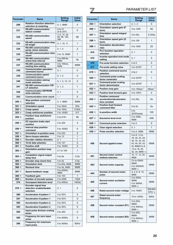
PARAMETER LIST
299 Rotation direction detection selection at restarting 0, 1, 9999 0
331 RS-485 communication station number
0 to 31(0 to 247) 0
332 RS-485 communication speed
3, 6, 12, 24, 48, 96, 192, 384
96
333 RS-485 communication stop bit length 0, 1, 10, 11 1
334 RS-485 communication parity check selection 0, 1, 2 2
335 RS-485 communication retry count 0 to 10, 9999 1
336 RS-485 communication check time interval
0 to 999.8s, 9999 0s
337 RS-485 communication waiting time setting
0 to 150ms, 9999 9999
338 Communication operation command source 0, 1 0
339 Communication speed command source 0, 1, 2 0
340 Communication startup mode selection 0, 1, 2, 10, 12 0
341 RS-485 communication CR/LF selection 0, 1, 2 1
342 Communication EEPROM write selection 0, 1 0
343 Communication error count ⎯ 0
350 *7 Stop position command selection 0, 1, 9999 9999
351 *7 Orientation speed 0 to 30Hz 2Hz352 *7 Creep speed 0 to 10Hz 0.5Hz353 *7 Creep switchover position 0 to 16383 511
354 *7 Position loop switchover position 0 to 8191 96
355 *7 DC injection brake start position 0 to 255 5
356 *7 Internal stop position command 0 to 16383 0
357 *7 Orientation in-position zone 0 to 255 5358 *7 Servo torque selection 0 to 13 1359 *7 Encoder rotation direction 0, 1 1360 *7 16 bit data selection 0 to 127 0361 *7 Position shift 0 to 16383 0
362 *7 Orientation position loop gain 0.1 to 100 1
363 *7 Completion signal output delay time 0 to 5s 0.5s
364 *7 Encoder stop check time 0 to 5s 0.5s365 *7 Orientation limit 0 to 60s, 9999 9999366 *7 Recheck time 0 to 5s, 9999 9999
367 *7 Speed feedback range 0 to 400Hz, 9999 9999
368 *7 Feedback gain 0 to 100 1369 *7 Number of encoder pulses 0 to 4096 1024374 Overspeed detection level 0 to 400Hz 140Hz
376 *7Encoder signal loss detection enable/disable selection
0, 1 0
380 Acceleration S-pattern 1 0 to 50% 0
381 Deceleration S-pattern 1 0 to 50% 0
382 Acceleration S-pattern 2 0 to 50% 0
383 Deceleration S-pattern 2 0 to 50% 0
384 Input pulse division scaling factor 0 to 250 0
385 Frequency for zero input pulse 0 to 400Hz 0
386 Frequency for maximum input pulse 0 to 400Hz 60Hz
Parameter Name Setting Range
Initial Value
393 *7 Orientation selection 0, 1, 2 0
396 *7 Orientation speed gain (P term) 0 to 1000 60
397 *7 Orientation speed integral time 0 to 20s 0.333s
398 *7 Orientation speed gain (D term) 0 to 100 1
399 *7 Orientation deceleration ratio 0 to 1000 20
414 PLC function operation selection 0, 1 0
415 Inverter operation lock mode setting 0, 1 0
416 Pre-scale function selection 0 to 5 0
417 Pre-scale setting value 0 to 32767 1
419 *7 Position command source selection 0 to 2 0
420 *7 Command pulse scaling factor numerator 0 to 32767 1
421 *7 Command pulse scaling factor denominator 0 to 32767 1
422 *7 Position loop gain 0 to 150sec-1 25sec-1
423 *7 Position feed forward gain 0 to 100% 0
424 *7Position command acceleration/deceleration time constant
0 to 50s 0s
425 *7 Position feed forward command filter 0 to 5s 0s
426 *7 In-position width 0 to 32767pulse 100
427 *7 Excessive level error 0 to 400K, 9999
40K
428 *7 Command pulse selection 0 to 5 0
429 *7 Clear signal selection 0, 1 1
430 *7 Pulse monitor selection 0 to 5, 9999 9999
450 Second applied motor
0 to 8, 13 to 18, 20, 23, 24, 30, 33, 34, 40, 43, 44, 50, 53, 54, 9999/0 to 8, 13 to 18, 30, 33, 34, 9999 *5
9999
451 Second motor control method selection
10, 11, 12, 20, 9999 9999
453 Second motor capacity
0.4 to 55kW, 9999/0 to 3600kW, 9999 *2
9999
454 Number of second motor poles
2, 4, 6, 8, 10, 9999 9999
455 Second motor excitation current
0 to 500A,9999/0 to 3600A, 9999 *2
9999
456 Rated second motor voltage 0 to 1000V 200/400/575V *6
457 Rated second motor frequency 10 to 120Hz 60Hz
458 Second motor constant (R1)
0 to 50Ω, 9999/0 to 400mΩ, 9999 *2
9999
459 Second motor constant (R2)
0 to 50Ω, 9999/0 to 400mΩ, 9999 *2
9999
Parameter Name Setting Range
Initial Value
25
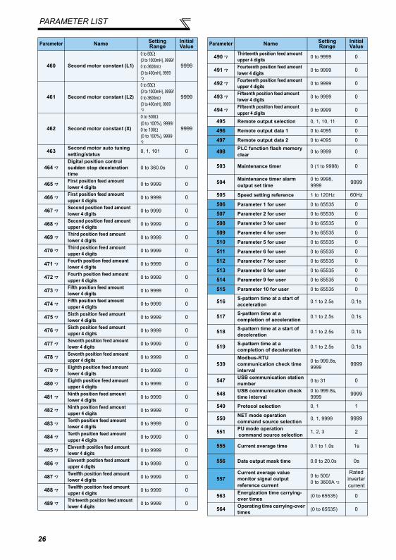
PARAMETER LIST
460 Second motor constant (L1)
0 to 50Ω (0 to 1000mH), 9999/0 to 3600mΩ (0 to 400mH), 9999 *2
9999
461 Second motor constant (L2)
0 to 50Ω (0 to 1000mH), 9999/0 to 3600mΩ (0 to 400mH), 9999 *2
9999
462 Second motor constant (X)
0 to 500Ω (0 to 100%), 9999/0 to 100Ω (0 to 100%), 9999 *2
9999
463 Second motor auto tuning setting/status 0, 1, 101 0
464 *7Digital position control sudden stop deceleration time
0 to 360.0s 0
465 *7 First position feed amount lower 4 digits 0 to 9999 0
466 *7 First position feed amount upper 4 digits 0 to 9999 0
467 *7 Second position feed amount lower 4 digits 0 to 9999 0
468 *7 Second position feed amount upper 4 digits 0 to 9999 0
469 *7 Third position feed amount lower 4 digits 0 to 9999 0
470 *7 Third position feed amount upper 4 digits 0 to 9999 0
471 *7 Fourth position feed amount lower 4 digits 0 to 9999 0
472 *7 Fourth position feed amount upper 4 digits 0 to 9999 0
473 *7 Fifth position feed amount lower 4 digits 0 to 9999 0
474 *7 Fifth position feed amount upper 4 digits 0 to 9999 0
475 *7 Sixth position feed amount lower 4 digits 0 to 9999 0
476 *7 Sixth position feed amount upper 4 digits 0 to 9999 0
477 *7 Seventh position feed amount lower 4 digits 0 to 9999 0
478 *7 Seventh position feed amount upper 4 digits 0 to 9999 0
479 *7 Eighth position feed amount lower 4 digits 0 to 9999 0
480 *7 Eighth position feed amount upper 4 digits 0 to 9999 0
481 *7 Ninth position feed amount lower 4 digits 0 to 9999 0
482 *7 Ninth position feed amount upper 4 digits 0 to 9999 0
483 *7 Tenth position feed amount lower 4 digits 0 to 9999 0
484 *7 Tenth position feed amount upper 4 digits 0 to 9999 0
485 *7 Eleventh position feed amount lower 4 digits 0 to 9999 0
486 *7 Eleventh position feed amount upper 4 digits 0 to 9999 0
487 *7 Twelfth position feed amount lower 4 digits 0 to 9999 0
488 *7 Twelfth position feed amount upper 4 digits 0 to 9999 0
489 *7 Thirteenth position feed amount lower 4 digits 0 to 9999 0
Parameter Name Setting Range
Initial Value
490 *7 Thirteenth position feed amount upper 4 digits 0 to 9999 0
491 *7 Fourteenth position feed amount lower 4 digits 0 to 9999 0
492 *7 Fourteenth position feed amount upper 4 digits 0 to 9999 0
493 *7 Fifteenth position feed amount lower 4 digits 0 to 9999 0
494 *7 Fifteenth position feed amount upper 4 digits 0 to 9999 0
495 Remote output selection 0, 1, 10, 11 0
496 Remote output data 1 0 to 4095 0
497 Remote output data 2 0 to 4095 0
498 PLC function flash memory clear 0 to 9999 0
503 Maintenance timer 0 (1 to 9998) 0
504 Maintenance timer alarm output set time
0 to 9998, 9999 9999
505 Speed setting reference 1 to 120Hz 60Hz
506 Parameter 1 for user 0 to 65535 0
507 Parameter 2 for user 0 to 65535 0
508 Parameter 3 for user 0 to 65535 0
509 Parameter 4 for user 0 to 65535 0
510 Parameter 5 for user 0 to 65535 0
511 Parameter 6 for user 0 to 65535 0
512 Parameter 7 for user 0 to 65535 0
513 Parameter 8 for user 0 to 65535 0
514 Parameter 9 for user 0 to 65535 0
515 Parameter 10 for user 0 to 65535 0
516 S-pattern time at a start of acceleration 0.1 to 2.5s 0.1s
517 S-pattern time at a completion of acceleration 0.1 to 2.5s 0.1s
518 S-pattern time at a start of deceleration 0.1 to 2.5s 0.1s
519 S-pattern time at a completion of deceleration 0.1 to 2.5s 0.1s
539Modbus-RTU communication check time interval
0 to 999.8s, 9999 9999
547 USB communication station number 0 to 31 0
548 USB communication check time interval
0 to 999.8s, 9999 9999
549 Protocol selection 0, 1 1
550 NET mode operation command source selection 0, 1, 9999 9999
551 PU mode operation command source selection 1, 2, 3 2
555 Current average time 0.1 to 1.0s 1s
556 Data output mask time 0.0 to 20.0s 0s
557Current average value monitor signal output reference current
0 to 500/0 to 3600A *2
Rated inverter current
563 Energization time carrying-over times (0 to 65535) 0
564 Operating time carrying-over times (0 to 65535) 0
Parameter Name Setting Range
Initial Value
26
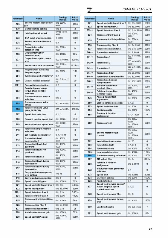
PARAMETER LIST
569 Second motor speed control gain
0 to 200%, 9999 9999
570 Multiple rating setting 0 to 3 2
571 Holding time at a start 0.0 to 10.0s, 9999 9999
573 4mA input check selection 1, 9999 9999
574 Second motor online auto tuning 0, 1 0
575 Output interruption detection time
0 to 3600s, 9999 1s
576 Output interruption detection level 0 to 400Hz 0Hz
577 Output interruption cancel level 900 to 1100% 1000%
611 Acceleration time at a restart 0 to 3600s,9999 5/15s *2
665 Regeneration avoidance frequency gain 0 to 200% 100
684 Tuning data unit switchover 0, 1 0
800 Control method selection 0 to 5, 9 to 12, 20 20
802 *7 Pre-excitation selection 0, 1 0
803Constant power range torque characteristic selection
0, 1 0
804 Torque command source selection 0 to 6 0
805 Torque command value (RAM) 600 to 1400% 1000%
806 Torque command value (RAM,EEPROM) 600 to 1400% 1000%
807 Speed limit selection 0, 1, 2 0
808 Forward rotation speed limit 0 to 120Hz 60Hz
809 Reverse rotation speed limit 0 to 120Hz, 9999 9999
810 Torque limit input method selection 0, 1 0
811 Set resolution switchover 0, 1, 10, 11 0
812 Torque limit level (regeneration)
0 to 400%, 9999 9999
813 Torque limit level (3rd quadrant)
0 to 400%, 9999 9999
814 Torque limit level (4th quadrant)
0 to 400%, 9999 9999
815 Torque limit level 2 0 to 400%, 9999 9999
816 Torque limit level during acceleration
0 to 400%, 9999 9999
817 Torque limit level during deceleration
0 to 400%, 9999 9999
818 Easy gain tuning response level setting 1 to 15 2
819 Easy gain tuning selection 0 to 2 0820 Speed control P gain 1 0 to 1000% 60%821 Speed control integral time 1 0 to 20s 0.333s822 Speed setting filter 1 0 to 5s, 9999 9999
823 *7 Speed detection filter 1 0 to 0.1s 0.001s824 Torque control P gain 1 0 to 200% 100%
825 Torque control integral time 1 0 to 500ms 5ms
826 Torque setting filter 1 0 to 5s, 9999 9999827 Torque detection filter 1 0 to 0.1s 0s828 Model speed control gain 0 to 1000% 60%
830 Speed control P gain 2 0 to 1000%, 9999 9999
Parameter Name Setting Range
Initial Value
831 Speed control integral time 2 0 to 20s, 9999 9999832 Speed setting filter 2 0 to 5s, 9999 9999
833 *7 Speed detection filter 2 0 to 0.1s, 9999 9999
834 Torque control P gain 2 0 to 200%, 9999 9999
835 Torque control integral time 2
0 to 500ms, 9999 9999
836 Torque setting filter 2 0 to 5s, 9999 9999837 Torque detection filter 2 0 to 0.1s, 9999 9999
840 *7 Torque bias selection 0 to 3, 9999 9999
841 *7 Torque bias 1 600 to 1400%, 9999 9999
842 *7 Torque bias 2 600 to 1400%, 9999 9999
843 *7 Torque bias 3 600 to 1400%, 9999 9999
844 *7 Torque bias filter 0 to 5s, 9999 9999845 *7 Torque bias operation time 0 to 5s, 9999 9999
846 *7 Torque bias balance compensation 0 to 10V, 9999 9999
847 *7 Fall-time torque bias terminal 1 bias
0 to 400%, 9999 9999
848 *7 Fall-time torque bias terminal 1 gain
0 to 400%, 9999 9999
849 Analog input offset adjustment 0 to 200% 100%
850 Brake operation selection 0, 1, 2 0853 Speed deviation time 0 to 100s 1s854 Excitation ratio 0 to 100% 100%
858 Terminal 4 function assignment 0, 1, 4, 9999 0
859 Torque current
0 to 500A, 9999/0 to 3600A, 9999 *2
9999
860 Second motor torque current
0 to 500A, 9999/0 to 3600A, 9999 *2
9999
862 Notch filter time constant 0 to 60 0863 Notch filter depth 0, 1, 2, 3 0864 Torque detection 0 to 400% 150%865 Low speed detection 0 to 400Hz 1.5Hz866 Torque monitoring reference 0 to 400% 150%867 AM output filter 0 to 5s 0.01s
868 Terminal 1 function assignment 0 to 6, 9999 0
872 Input phase loss protection selection 0, 1 0
873 Speed limit 0 to 120Hz 20Hz874 OLT level setting 0 to 200% 150%875 Fault definition 0, 1 0
877Speed feed forward control/model adaptive speed control selection
0, 1, 2 0
878 Speed feed forward filter 0 to 1s 0s
879 Speed feed forward torque limit 0 to 400% 150%
880 Load inertia ratio 0 to 200 times 7
881 Speed feed forward gain 0 to 1000% 0%
Parameter Name Setting Range
Initial Value
27
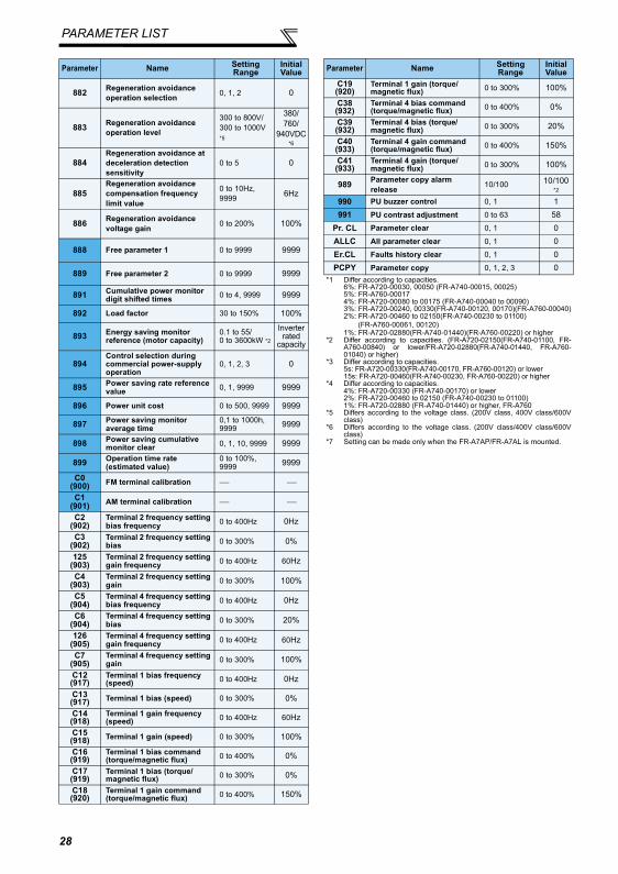
PARAMETER LIST
882 Regeneration avoidance operation selection 0, 1, 2 0
883 Regeneration avoidance operation level
300 to 800V/300 to 1000V *5
380/760/
940VDC *6
884Regeneration avoidance at deceleration detection sensitivity
0 to 5 0
885Regeneration avoidance compensation frequency limit value
0 to 10Hz, 9999 6Hz
886 Regeneration avoidance voltage gain 0 to 200% 100%
888 Free parameter 1 0 to 9999 9999
889 Free parameter 2 0 to 9999 9999
891 Cumulative power monitor digit shifted times 0 to 4, 9999 9999
892 Load factor 30 to 150% 100%
893 Energy saving monitor reference (motor capacity)
0.1 to 55/0 to 3600kW *2
Inverterrated
capacity
894Control selection during commercial power-supply operation
0, 1, 2, 3 0
895 Power saving rate reference value 0, 1, 9999 9999
896 Power unit cost 0 to 500, 9999 9999
897 Power saving monitor average time
0,1 to 1000h, 9999 9999
898 Power saving cumulative monitor clear 0, 1, 10, 9999 9999
899 Operation time rate (estimated value)
0 to 100%, 9999 9999
C0(900) FM terminal calibration ⎯ ⎯
C1(901) AM terminal calibration ⎯ ⎯
C2(902)
Terminal 2 frequency setting bias frequency 0 to 400Hz 0Hz
C3(902)
Terminal 2 frequency setting bias 0 to 300% 0%
125(903)
Terminal 2 frequency setting gain frequency 0 to 400Hz 60Hz
C4(903)
Terminal 2 frequency setting gain 0 to 300% 100%
C5(904)
Terminal 4 frequency setting bias frequency 0 to 400Hz 0Hz
C6(904)
Terminal 4 frequency setting bias 0 to 300% 20%
126(905)
Terminal 4 frequency setting gain frequency 0 to 400Hz 60Hz
C7(905)
Terminal 4 frequency setting gain 0 to 300% 100%
C12(917)
Terminal 1 bias frequency (speed) 0 to 400Hz 0Hz
C13(917) Terminal 1 bias (speed) 0 to 300% 0%
C14(918)
Terminal 1 gain frequency (speed) 0 to 400Hz 60Hz
C15(918) Terminal 1 gain (speed) 0 to 300% 100%
C16(919)
Terminal 1 bias command (torque/magnetic flux) 0 to 400% 0%
C17(919)
Terminal 1 bias (torque/magnetic flux) 0 to 300% 0%
C18(920)
Terminal 1 gain command (torque/magnetic flux) 0 to 400% 150%
Parameter Name Setting Range
Initial Value
C19(920)
Terminal 1 gain (torque/magnetic flux) 0 to 300% 100%
C38(932)
Terminal 4 bias command (torque/magnetic flux) 0 to 400% 0%
C39(932)
Terminal 4 bias (torque/magnetic flux) 0 to 300% 20%
C40(933)
Terminal 4 gain command (torque/magnetic flux) 0 to 400% 150%
C41(933)
Terminal 4 gain (torque/magnetic flux) 0 to 300% 100%
989 Parameter copy alarm release 10/100 10/100
*2
990 PU buzzer control 0, 1 1991 PU contrast adjustment 0 to 63 58
Pr. CL Parameter clear 0, 1 0ALLC All parameter clear 0, 1 0Er.CL Faults history clear 0, 1 0PCPY Parameter copy 0, 1, 2, 3 0
*1 Differ according to capacities.6%: FR-A720-00030, 00050 (FR-A740-00015, 00025)5%: FR-A760-000174%: FR-A720-00080 to 00175 (FR-A740-00040 to 00090)3%: FR-A720-00240, 00330(FR-A740-00120, 00170)(FR-A760-00040)2%: FR-A720-00460 to 02150(FR-A740-00230 to 01100) (FR-A760-00061, 00120)1%: FR-A720-02880(FR-A740-01440)(FR-A760-00220) or higher
*2 Differ according to capacities. (FR-A720-02150(FR-A740-01100, FR-A760-00840) or lower/FR-A720-02880(FR-A740-01440, FR-A760-01040) or higher)
*3 Differ according to capacities.5s: FR-A720-00330(FR-A740-00170, FR-A760-00120) or lower15s: FR-A720-00460(FR-A740-00230, FR-A760-00220) or higher
*4 Differ according to capacities. 4%: FR-A720-00330 (FR-A740-00170) or lower2%: FR-A720-00460 to 02150 (FR-A740-00230 to 01100)1%: FR-A720-02880 (FR-A740-01440) or higher, FR-A760
*5 Differs according to the voltage class. (200V class, 400V class/600Vclass)
*6 Differs according to the voltage class. (200V class/400V class/600Vclass)
*7 Setting can be made only when the FR-A7AP/FR-A7AL is mounted.
Parameter Name Setting Range
Initial Value
28
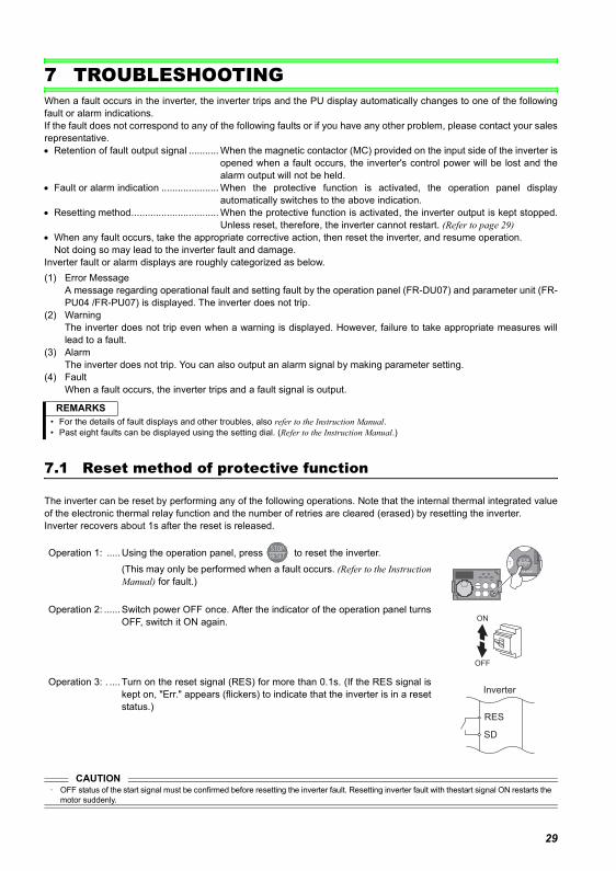
TROUBLESHOOTING
7 TROUBLESHOOTINGWhen a fault occurs in the inverter, the inverter trips and the PU display automatically changes to one of the followingfault or alarm indications.If the fault does not correspond to any of the following faults or if you have any other problem, please contact your salesrepresentative.• Retention of fault output signal ........... When the magnetic contactor (MC) provided on the input side of the inverter is
opened when a fault occurs, the inverter's control power will be lost and thealarm output will not be held.
• Fault or alarm indication ..................... When the protective function is activated, the operation panel displayautomatically switches to the above indication.
• Resetting method................................ When the protective function is activated, the inverter output is kept stopped.Unless reset, therefore, the inverter cannot restart. (Refer to page 29)
• When any fault occurs, take the appropriate corrective action, then reset the inverter, and resume operation.Not doing so may lead to the inverter fault and damage.
Inverter fault or alarm displays are roughly categorized as below.(1) Error Message
A message regarding operational fault and setting fault by the operation panel (FR-DU07) and parameter unit (FR-PU04 /FR-PU07) is displayed. The inverter does not trip.
(2) WarningThe inverter does not trip even when a warning is displayed. However, failure to take appropriate measures willlead to a fault.
(3) AlarmThe inverter does not trip. You can also output an alarm signal by making parameter setting.
(4) FaultWhen a fault occurs, the inverter trips and a fault signal is output.
7.1 Reset method of protective function
The inverter can be reset by performing any of the following operations. Note that the internal thermal integrated valueof the electronic thermal relay function and the number of retries are cleared (erased) by resetting the inverter.Inverter recovers about 1s after the reset is released.
REMARKS• For the details of fault displays and other troubles, also refer to the Instruction Manual.• Past eight faults can be displayed using the setting dial. (Refer to the Instruction Manual.)
Operation 1: .....Using the operation panel, press to reset the inverter.(This may only be performed when a fault occurs. (Refer to the InstructionManual) for fault.)
Operation 2: ......Switch power OFF once. After the indicator of the operation panel turnsOFF, switch it ON again.
Operation 3: . ....Turn on the reset signal (RES) for more than 0.1s. (If the RES signal iskept on, "Err." appears (flickers) to indicate that the inverter is in a resetstatus.)
ON
OFF
Inverter
RES
SD
CAUTION· OFF status of the start signal must be confirmed before resetting the inverter fault. Resetting inverter fault with thestart signal ON restarts the
motor suddenly.
29
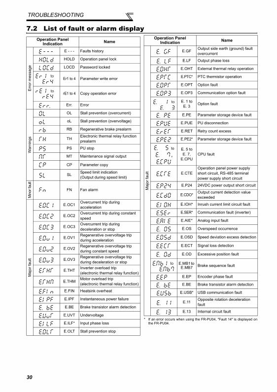
TROUBLESHOOTING
7.2 List of fault or alarm display
* If an error occurs when using the FR-PU04, "Fault 14" is displayed onthe FR-PU04.
Operation Panel Indication Name
Erro
r mes
sage
E - - - Faults history
HOLD Operation panel lock
LOCD Password locked
Er1 to 4 Parameter write error
rE1 to 4 Copy operation error
Err. Error
War
ning
s
OL Stall prevention (overcurrent)
oL Stall prevention (overvoltage)
RB Regenerative brake prealarm
TH Electronic thermal relay function prealarm
PS PU stop
MT Maintenance signal output
CP Parameter copy
SL Speed limit indication(Output during speed limit)
Min
or fa
ult
FN Fan alarm
Maj
or fa
ult
E.OC1 Overcurrent trip during acceleration
E.OC2 Overcurrent trip during constant speed
E.OC3 Overcurrent trip during deceleration or stop
E.OV1 Regenerative overvoltage trip during acceleration
E.OV2 Regenerative overvoltage trip during constant speed
E.OV3 Regenerative overvoltage trip during deceleration or stop
E.THT Inverter overload trip(electronic thermal relay function)
E.THM Motor overload trip(electronic thermal relay function)
E.FIN Heatsink overheat
E.IPF Instantaneous power failure
E.BE Brake transistor alarm detection
E.UVT Undervoltage
E.ILF* Input phase loss
E.OLT Stall prevention stop
to
to
Maj
or fa
ult
E.GF Output side earth (ground) fault overcurrent
E.LF Output phase loss
E.OHT External thermal relay operation
E.PTC* PTC thermistor operation
E.OPT Option fault
E.OP3 Communication option fault
E. 1 to E. 3 Option fault
E.PE Parameter storage device fault
E.PUE PU disconnection
E.RET Retry count excess
E.PE2* Parameter storage device fault
to,
E. 5 to E. 7,
E.CPUCPU fault
E.CTEOperation panel power supply short circuit, RS-485 terminal power supply short circuit
E.P24 24VDC power output short circuit
E.CDO* Output current detection value exceeded
E.IOH* Inrush current limit circuit fault
E.SER* Communication fault (inverter)
E.AIE* Analog input fault
E.OS Overspeed occurrence
E.OSD Speed deviation excess detection
E.ECT Signal loss detection
E.OD Excessive position fault
E.MB1 to E.MB7 Brake sequence fault
E.EP Encoder phase fault
E.BE Brake transistor alarm detection
E.USB* USB communication fault
E.11 Opposite rotation deceleration fault
E.13 Internal circuit fault
Operation Panel Indication Name
to
to
30
The EU Directives are issued to standardize different national regulations of the EU Member States and to facilitate free movement of theequipment, whose safety is ensured, in the EU territory.Since 1996, compliance with the EMC Directive that is one of the EU Directives has been legally required. Since 1997, compliance with theLow Voltage Directive, another EU Directive, has been also legally required. When a manufacturer confirms its equipment to be compliantwith the EMC Directive and the Low Voltage Directive, the manufacturer must declare the conformity and affix the CE marking.
The authorized representative in the EUThe authorized representative in the EU is shown below.Name: Mitsubishi Electric Europe B.V.Address: Gothaer Strasse 8, 40880 Ratingen, GermanyNoteWe declare that this inverter conforms with the EMC Directive in industrial environments and affix the CE marking on the inverter. Whenusing the inverter in a residential area, take appropriate measures and ensure the conformity of the inverter used in the residential area.
(1) EMC DirectiveWe declare that this inverter conforms with the EMC Directive and affix the CE marking on the inverter.
• EMC Directive: 2004/108/EC• Standard(s): EN61800-3:2004 (Second environment / PDS Category "C3")
Note: First environmentEnvironment including residential buildings. Includes buildings directly connected without a transformer to the low voltage powersupply network which supplies power to residential buildings.
Second environmentEnvironment including all buildings except buildings directly connected without a transformer to the low voltage power supplynetwork which supplies power to residential buildings.
NoteSet the EMC filter valid and install the inverter and perform wiring according to the following instructions.* The inverter is equipped with a built-in EMC filter. Set the EMC filter valid. (The EMC filter is invalid when shipped from the factory. (The
FR-A720-00030 and 00050 are always valid.))* Connect the inverter to an earthed power supply.* Install a motor and a control cable written in the EMC Installation Manual (BCN-A21041-204) according to the instruction.* The cable length between the inverter and the motor is 5 m (16.4 feet) maximum.* Confirm that the inverter conforms with the EMC Directive as the industrial drives application for final installation.
Appendix 1 Instructions for compliance with the EU Directives (FR-A720/A740 only)
31
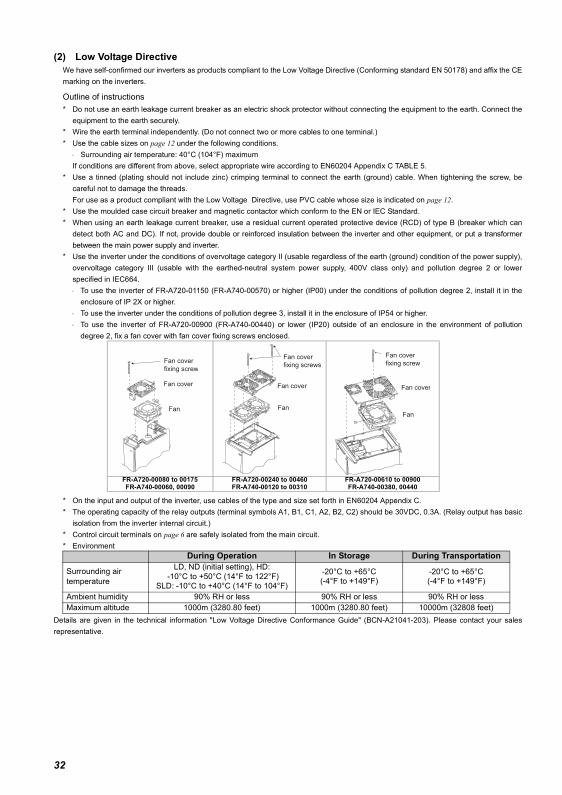
(2) Low Voltage DirectiveWe have self-confirmed our inverters as products compliant to the Low Voltage Directive (Conforming standard EN 50178) and affix the CEmarking on the inverters.
Outline of instructions* Do not use an earth leakage current breaker as an electric shock protector without connecting the equipment to the earth. Connect the
equipment to the earth securely.* Wire the earth terminal independently. (Do not connect two or more cables to one terminal.)* Use the cable sizes on page 12 under the following conditions.
⋅ Surrounding air temperature: 40°C (104°F) maximumIf conditions are different from above, select appropriate wire according to EN60204 Appendix C TABLE 5.
* Use a tinned (plating should not include zinc) crimping terminal to connect the earth (ground) cable. When tightening the screw, becareful not to damage the threads.For use as a product compliant with the Low Voltage Directive, use PVC cable whose size is indicated on page 12.
* Use the moulded case circuit breaker and magnetic contactor which conform to the EN or IEC Standard. * When using an earth leakage current breaker, use a residual current operated protective device (RCD) of type B (breaker which can
detect both AC and DC). If not, provide double or reinforced insulation between the inverter and other equipment, or put a transformerbetween the main power supply and inverter.
* Use the inverter under the conditions of overvoltage category II (usable regardless of the earth (ground) condition of the power supply),overvoltage category III (usable with the earthed-neutral system power supply, 400V class only) and pollution degree 2 or lowerspecified in IEC664.⋅ To use the inverter of FR-A720-01150 (FR-A740-00570) or higher (IP00) under the conditions of pollution degree 2, install it in the
enclosure of IP 2X or higher. ⋅ To use the inverter under the conditions of pollution degree 3, install it in the enclosure of IP54 or higher.⋅ To use the inverter of FR-A720-00900 (FR-A740-00440) or lower (IP20) outside of an enclosure in the environment of pollution
degree 2, fix a fan cover with fan cover fixing screws enclosed.
* On the input and output of the inverter, use cables of the type and size set forth in EN60204 Appendix C.* The operating capacity of the relay outputs (terminal symbols A1, B1, C1, A2, B2, C2) should be 30VDC, 0.3A. (Relay output has basic
isolation from the inverter internal circuit.)* Control circuit terminals on page 6 are safely isolated from the main circuit.* Environment
Details are given in the technical information "Low Voltage Directive Conformance Guide" (BCN-A21041-203). Please contact your salesrepresentative.
FR-A720-00080 to 00175FR-A740-00060, 00090
FR-A720-00240 to 00460FR-A740-00120 to 00310
FR-A720-00610 to 00900FR-A740-00380, 00440
During Operation In Storage During Transportation
Surrounding air temperature
LD, ND (initial setting), HD: -10°C to +50°C (14°F to 122°F)
SLD: -10°C to +40°C (14°F to 104°F)
-20°C to +65°C(-4°F to +149°F)
-20°C to +65°C(-4°F to +149°F)
Ambient humidity 90% RH or less 90% RH or less 90% RH or lessMaximum altitude 1000m (3280.80 feet) 1000m (3280.80 feet) 10000m (32808 feet)
Fan cover
fixing screw
Fan cover
Fan
Fan cover
fixing screws
Fan cover
Fan
Fan cover
fixing screw
Fan cover
Fan
32
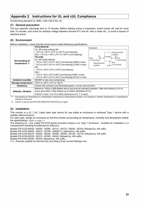
(Conforming standard UL 508C, CSA C22.2 No.14)
(1) General precautionThe bus capacitor discharge time is 10 minutes. Before starting wiring or inspection, switch power off, wait for morethan 10 minutes, and check for residual voltage between terminal P/+ and N/- with a meter etc., to avoid a hazard ofelectrical shock.
(2) EnvironmentBefore installation, check that the environment meets following specifications.
(3) InstallationThis inverter is a UL / cUL Listed open type device for use inside an enclosure or enclosed Type 1 device with asuitably rated enclosure.For open type, design an enclosure so that the inverter surrounding air temperature, humidity and atmosphere satisfythe specifications. (Refer to page 1.)The following UL / cUL Listed FR-A700 Series Inverters employ a UL Type 1 Enclosure - Suitable for Installation in aCompartment Handling Conditioned Air (Plenum):Models FR-A720-00030, -00050, -00080, -00110, -00175, -00240, -00330, followed by -N4 suffix.Models FR-A720-00460, -00610, -00760, -00900(*1), followed by -NA suffix.Models FR-A740-00015, -00025, -00040, -00060, -00090, -00120, -00170, followed by -N4 suffix.Models FR-A740-00230, -00310, -00380, -00440, followed by -NA suffix.Models FR-A760-00220, -00330, followed by -NA suffix.(*1) - Denotes suitable for Normal Duty and Heavy Duty Current Ratings only.
Appendix 2 Instructions for UL and cUL Compliance
Surrounding airtemperature *1
FR-A720/A740LD, ND (initial setting),HD: -10°C to + 50°C (14°F to 122°F) (non-freezing)SLD: -10°C to + 40°C (14°F to 104°F) (non-freezing)FR-A760LD, ND (initial setting): -10°C to +40°C (14°F to 104°F) (non-freezing) (00840 or less) -10°C to +50°C (14°F to 122°F) (non-freezing) (01040 or more)HD: -10°C to + 40°C (14°F to 104°F) (non-freezing)SLD: -10°C to +30°C (14°F to 86°F) (non-freezing) (00061 or less) -10°C to +40°C (14°F to 104°F) (non-freezing) (00120 or more)
Ambient humidity 90%RH or less (non-condensing)Storage temperature -20°C to +65°C (-4°F to 149°F)
Ambience Indoors (No corrosive and flammable gases, oil mist, dust and dirt.)
Altitude, vibrationMaximum 1000m (3280.80feet) above sea level for standard operation. After that derate by 3% for every extra 500m (1640.40feet) up to 2500m (8202feet) (91%).5.9m/s2 or less *2 at 10 to 55Hz (directions of X, Y, Z axes)
*1 Surrounding Air Temperature is a temperature measured at a measurement position in an enclosure. Ambient Temperature is a temperatureoutside an enclosure.
*2 2.9m/s2 or less for the FR-A740-03250 (FR-A760-02210) or higher.
Enclosure
5cm
(1.97inches)
5cm
(1.97inches)
5cm
(1.97inches)
Measurement
position
Measurement
position
Inverter
33
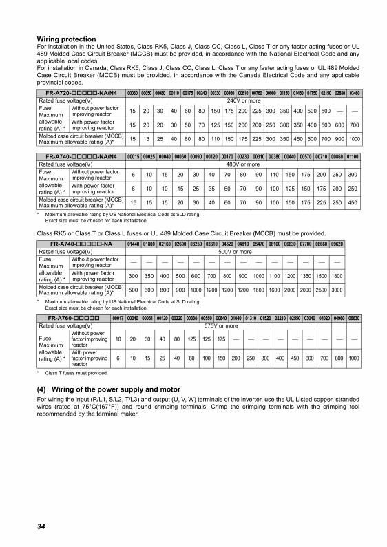
Wiring protectionFor installation in the United States, Class RK5, Class J, Class CC, Class L, Class T or any faster acting fuses or UL489 Molded Case Circuit Breaker (MCCB) must be provided, in accordance with the National Electrical Code and anyapplicable local codes.For installation in Canada, Class RK5, Class J, Class CC, Class L, Class T or any faster acting fuses or UL 489 MoldedCase Circuit Breaker (MCCB) must be provided, in accordance with the Canada Electrical Code and any applicableprovincial codes.
* Maximum allowable rating by US National Electrical Code at SLD rating.Exact size must be chosen for each installation.
Class RK5 or Class T or Class L fuses or UL 489 Molded Case Circuit Breaker (MCCB) must be provided.
* Maximum allowable rating by US National Electrical Code at SLD rating.Exact size must be chosen for each installation.
* Class T fuses must provided.
(4) Wiring of the power supply and motorFor wiring the input (R/L1, S/L2, T/L3) and output (U, V, W) terminals of the inverter, use the UL Listed copper, strandedwires (rated at 75°C(167°F)) and round crimping terminals. Crimp the crimping terminals with the crimping toolrecommended by the terminal maker.
FR-A720- -NA/N4 00030 00050 00080 00110 00175 00240 00330 00460 00610 00760 00900 01150 01450 01750 02150 02880 03460Rated fuse voltage(V) 240V or moreFuseMaximumallowablerating (A) *
Without power factor improving reactor 15 20 30 40 60 80 150 175 200 225 300 350 400 500 500 ⎯ ⎯
With power factor improving reactor 15 20 20 30 50 70 125 150 200 200 250 300 350 400 500 600 700
Molded case circuit breaker (MCCB)Maximum allowable rating (A)* 15 15 25 40 60 80 110 150 175 225 300 350 450 500 700 900 1000
FR-A740- -NA/N4 00015 00025 00040 00060 00090 00120 00170 00230 00310 00380 00440 00570 00710 00860 01100Rated fuse voltage(V) 480V or moreFuseMaximumallowablerating (A) *
Without power factor improving reactor 6 10 15 20 30 40 70 80 90 110 150 175 200 250 300
With power factor improving reactor 6 10 10 15 25 35 60 70 90 100 125 150 175 200 250
Molded case circuit breaker (MCCB)Maximum allowable rating (A)* 15 15 15 20 30 40 60 70 90 100 150 175 225 250 450
FR-A740- -NA 01440 01800 02160 02600 03250 03610 04320 04810 05470 06100 06830 07700 08660 09620Rated fuse voltage(V) 500V or moreFuseMaximumallowablerating (A) *
Without power factor improving reactor ⎯ ⎯ ⎯ ⎯ ⎯ ⎯ ⎯ ⎯ ⎯ ⎯ ⎯ ⎯ ⎯ ⎯
With power factor improving reactor 300 350 400 500 600 700 800 900 1000 1100 1200 1350 1500 1800
Molded case circuit breaker (MCCB)Maximum allowable rating (A)* 500 600 800 900 1000 1200 1200 1200 1600 1600 2000 2000 2500 3000
FR-A760- 00017 00040 00061 00120 00220 00330 00550 00840 01040 01310 01520 02210 02550 03040 04020 04960 06630Rated fuse voltage(V) 575V or more
FuseMaximumallowablerating (A) *
Without power factor improving reactor
10 20 30 40 80 125 125 175 ⎯ ⎯ ⎯ ⎯ ⎯ ⎯ ⎯ ⎯ ⎯
With power factor improving reactor
6 10 15 25 40 60 100 150 200 250 300 400 450 600 700 800 1000
34
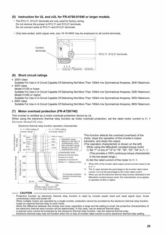
(5) Instruction for UL and cUL for FR-A760-01040 or larger models.• The R1/L11, S1/L21 terminals are only used for factory wiring.
Do not remove the jumper to R1/L11 and S1/L21 terminals.Do not connect wires to R1/L11 and S1/L21 terminals.
• Only bare ended, solid copper wire, size 16-18 AWG may be employed on all control terminals.
(6) Short circuit ratings• 200V class
Suitable For Use in A Circuit Capable Of Delivering Not More Than 100kA rms Symmetrical Amperes, 264V Maximum.• 400V class
Model 01100 or lowerSuitable For Use in A Circuit Capable Of Delivering Not More Than 100kA rms Symmetrical Amperes, 528V Maximum.Model 01440 or higherSuitable For Use in A Circuit Capable Of Delivering Not More Than 100kA rms Symmetrical Amperes, 550V Maximum.
• 600V classSuitable For Use in A Circuit Capable Of Delivering Not More Than 100kA rms Symmetrical Amperes, 660V Maximum.
(7) Motor overload protection (FR-A720/740)This inverter is certified as a motor overload protection device by UL.When using the electronic thermal relay function as motor overload protection, set the rated motor current to Pr. 9Electronic thermal O/L relay.
Electronic thermal relay function operation characteristic
This function detects the overload (overheat) of the motor, stops the operation of the inverter's output transistor, and stops the output. (The operation characteristic is shown on the left)
When using the Mitsubishi constant-torque motor1) Set "1" or any of "13" to "18", "50", "53", "54" in Pr. 71.
(This provides a 100% continuous torque characteristic in the low-speed range.)
2) Set the rated current of the motor in Pr. 9.*1 When 50% of the inverter rated output current (current value) is set
in Pr. 9 *2 The % value denotes the percentage to the inverter rated output
current. It is not the percentage to the motor rated current.*3 When you set the electronic thermal relay function dedicated to the
Mitsubishi constant-torque motor, this characteristic curve applies to operation at 6Hz or higher.
CAUTION⋅ Protective function by electronic thermal relay function is reset by inverter power reset and reset signal input. Avoid
unnecessary reset and power-off.⋅ When multiple motors are operated by a single inverter, protection cannot be provided by the electronic thermal relay function.
Install an external thermal relay to each motor.⋅ When the difference between the inverter and motor capacities is large and the setting is small, the protective characteristics of
the electronic thermal relay function will be deteriorated. In this case, use an external thermal relay.⋅ A special motor cannot be protected by the electronic thermal relay function. Use the external thermal relay.⋅ Electronic thermal relay may not function when 5% or less of inverter rated current is set to electronic thermal relay setting.
R1/L11, S1/L21 terminals
Control
terminals
For transistor protectionElectronic thermal relay function
52.5% 105%
50 100 150
60
120
180
240
50
60
70
6Hz
20Hz
10Hz
6Hz
0.5Hz
30Hz or more*3
20Hz
10Hz
0.5Hz
Pr. 9 = 50% setting of
inverter rating*1.2
Pr. 9 = 100% setting
of inverter rating*1.2
(s)
unit d
ispla
y in this
range
(min
) unit d
ispla
y in
this
range
Opera
tion tim
e (
min
)O
pera
tion tim
e (
s)
Characteristic when
electronic thermal relay
function for motor
protection is turned off
(When Pr. 9 setting is 0(A))
30Hz or more*3
Inverter output current (%) (% to the rated output current)
Operation range Range on the right of characteristic curve Non-operation range Range on the left of characteristic curve
35
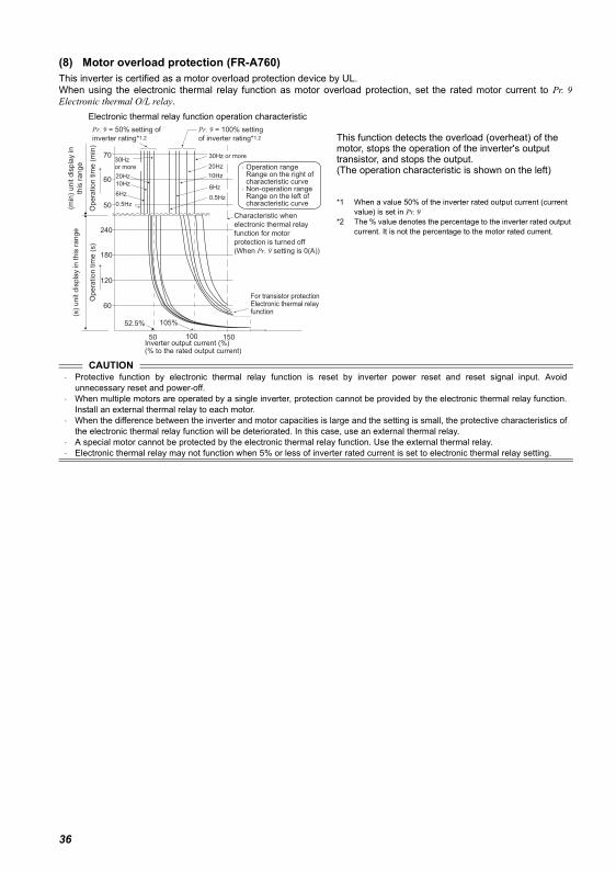
(8) Motor overload protection (FR-A760)This inverter is certified as a motor overload protection device by UL.When using the electronic thermal relay function as motor overload protection, set the rated motor current to Pr. 9Electronic thermal O/L relay.
Electronic thermal relay function operation characteristic
This function detects the overload (overheat) of the motor, stops the operation of the inverter's output transistor, and stops the output. (The operation characteristic is shown on the left)
*1 When a value 50% of the inverter rated output current (current value) is set in Pr. 9
*2 The % value denotes the percentage to the inverter rated output current. It is not the percentage to the motor rated current.
CAUTION⋅ Protective function by electronic thermal relay function is reset by inverter power reset and reset signal input. Avoid
unnecessary reset and power-off.⋅ When multiple motors are operated by a single inverter, protection cannot be provided by the electronic thermal relay function.
Install an external thermal relay to each motor.⋅ When the difference between the inverter and motor capacities is large and the setting is small, the protective characteristics of
the electronic thermal relay function will be deteriorated. In this case, use an external thermal relay.⋅ A special motor cannot be protected by the electronic thermal relay function. Use the external thermal relay.⋅ Electronic thermal relay may not function when 5% or less of inverter rated current is set to electronic thermal relay setting.
For transistor protectionElectronic thermal relay function
52.5% 105%
50 100 150
60
120
180
240
50
60
70
6Hz
20Hz
10Hz
6Hz
0.5Hz
30Hz or more
20Hz
10Hz
0.5Hz
Pr. 9 = 50% setting of
inverter rating*1.2
Pr. 9 = 100% setting
of inverter rating*1.2
(s)
unit d
ispla
y in this
range
(min
) unit d
ispla
y in
this
range
Opera
tion tim
e (
min
)O
pera
tion tim
e (
s)
Characteristic when
electronic thermal relay
function for motor
protection is turned off
(When Pr. 9 setting is 0(A))
30Hz or more
Inverter output current (%) (% to the rated output current)
Operation range Range on the right of characteristic curve Non-operation range Range on the left of characteristic curve
36
37
REVISIONS*The manual number is given on the bottom left of the back cover.
For Maximum Safety• Mitsubishi inverters are not designed or manufactured to be used in equipment or systems in situations that
can affect or endanger human life.• When considering this product for operation in special applications such as machinery or systems used in
passenger transportation, medical, aerospace, atomic power, electric power, or submarine repeatingapplications, please contact your nearest Mitsubishi sales representative.
• Although this product was manufactured under conditions of strict quality control, you are strongly advisedto install safety devices to prevent serious accidents when it is used in facilities where breakdowns of theproduct are likely to cause a serious accident.
• Please do not use this product for loads other than three-phase induction motors.
Print Date *Manual Number RevisionSep. 2005 IB-0600254ENG-A First editionOct. 2006 IB-0600254ENG-B
FR-A720-00030 to 00330-N4FR-A740-00015 to 00170-N4
Feb. 2007 IB-0600254ENG-CBreaker selection when using the inverter as UL or cUL listed productFR-A760-00017 to 00840-NA
Apr. 2007 IB-0600254ENG-DFR-A760-01040 to 04020-NA
Sep. 2007 IB-0600254ENG-E• Failsafe• Instruction for UL and cUL for FR-A760-01040 or larger models.
Jul. 2008 IB-0600254ENG-F• FR-A760-04960, 06630-NA
Jul. 2009 IB-0600254ENG-G• Appendix1 Instructions for Compliance with the EU Directives
Jun. 2011 IB-0600254ENG-H• Setting value "46" of Pr. 52, Pr. 54 and Pr. 158 (Monitor output selection)• Setting value "55, 155" of Pr. 190 to Pr. 196 (Terminal assignment of output
terminal)• Setting values “11, 13” for Pr. 270 Stop-on contact/load torque high-speed
frequency control selection• Pr. 296 Password lock level• Pr. 297 Password lock/unlock• Setting value "1" of Pr. 419 Position command source selection• Setting value "2" of Pr. 804 Torque command source selection• Setting value "2" for Pr. 850 Brake operation selection• Password locked (LOCD)
Addition
Addition
Addition
Addition
Addition
Modification
Addition
38
Before using this CD-ROM• The copyright and other rights of this CD-ROM all belong to Mitsubishi Electric Corporation. • No part of this CD-ROM may be copied or reproduced without the permission of Mitsubishi Electric Corporation. • Specifications of this CD-ROM are subject to change for modification without notice. • We are not responsible for any damages and lost earnings, etc. from use of this CD-ROM.• Microsoft, Windows, Microsoft WindowsNT are registered trademarks of Microsoft Corporation in the United States and/or other countries.
Adobe and Acrobat are registered trademarks of Adobe Systems Incorporated.Pentium is a registered trademark of Intel Corporation of the United States and/or other countries. Other company and product names herein are the trademarks and registered trademarks of their respective owners.
• Warranty• We do not provide a warranty against defects in this CD-ROM and related documents.
• Acrobat Reader• For use of Acrobat Reader, please follow use conditions established by Adobe Systems Incorporated.
Warning: This is a personal computer dedicated CD-ROM. Do not attempt to play it on ordinary audio devices. The loud volume may damage hearingand speakers.
When playing this CD-ROM on Windows OS♦ Operating environment
• The following system is required to read instruction manuals contained in this CD-ROM.
♦ Operating method of this CD-ROM
How to read instruction manualsStep 1. Start Windows and place this CD-ROM in the CD-ROM drive.Step 2. "FR-A700 series documentation" PDF automatically opens.Step 3. Click a manual you want to read in the "INSTRUCTION MANUAL" list.Step 4. PDF manual you clicked opens.
* Manual opening of this CD-ROMStep 1. Start Windows and place this CD-ROM in the CD-ROM drive.Step 2. Select a CD-ROM drive (example: D drive) of "My computer" and click the right mouse button. Then, click "open" in the context menu.Step 3. Open "INDEX.PDF" in the opened folder.Step 4. "FR-A700 series documentation" PDF opens. Operates according to the steps from "Step 3" of "How to read instruction manuals"
• PDF data of the instruction manual are stored in "MANUAL" folder on this CD-ROM.
Item Specifications
OSMicrosoft Windows 95 OSR 2.0, Windows 98 Second Edition, Windows Millennium Edition, Windows NT 4.0 with Service Pack 6, Windows 2000 with Service Pack 2, Windows XP Professional or Home Edition, Windows XP Tablet PC Edition
CPU Intel Pentium processorMemory 64MB of RAM
Hard disk 24MB of available hard-disk spaceCD-ROM drive Double speed or more (more than quadruple speed is recommended)
Monitor 800x600 dot or moreApplication Acrobat Reader 4.05 or more
IB-0600254ENG-H
HEAD OFFICE: TOKYO BUILDING 2-7-3, MARUNOUCHI, CHIYODA-KU, TOKYO 100-8310, JAPAN
MITSUBISHI ELECTRIC EUROPEEUROPE B.V.German BranchGothaer Straße 8D-40880 RatingenPhone: +49 (0) 21 02 / 486-0Hotline: +49 2102 1805 000-765 /-766Fax: +49 (0) 21 02 / 4 86-1 12 0e mail: [email protected] ELECTRIC FRANCEFRANCE25, Boulevard des BouvetsF-92741 Nanterre CedexPhone: +33 1 55 68 55 68Fax: +33 1 49 01 07 25e mail: [email protected] ELECTRIC ITALYEUROPE B.V.Italian BranchC.D. Colleoni-P. Perseo lng. 2Via Paracelso 12I-20041 Agrate Brianza (Ml)Phone: +39 (0) 39 / 60 53 1Fax: +39 (0) 39 / 60 53 312e mail: [email protected] ELECTRIC SPAINEUROPE B.V.Pol. lnd. Can Magi-C.Calle Joan Buscallá, 2-4 AC 420E-08190 Sant Cugat del VallésPhone: +34 (9) 3 / 565 31 31Fax: +34 (9) 3 / 589 29 48MITSUBISHI ELECTRIC UKEUROPE B.V.UK BranchTravellers LaneHatfield, Hertfordshire, AL10 8 XBPhone: +44 (0) 1707 / 27 61 00Fax: +44 (0) 1707 / 27 86 95MITSUBISHI ELECTRIC JAPANCORPORATIONTokyo Bldg.2-7-3 Marunouchi Chiyoda-KuTokyo 100-8310Phone: +81 (0) 3 / 32 18 31 76Fax: +81 (0) 3 / 32 18 24 22MITSUBISHI ELECTRIC USAAUTOMATION500 Corporate Woods ParkwayVernon Hills, Illinois 60061Phone: +1 (0) 847 / 478 21 00Fax: +1 (0) 847 / 478 03 27
GEVA AUSTRIAWiener Straße 89A-2500 BadenPhone: +43 (0) 2252 / 85 55 20Fax: +43 (0) 2252 / 488 60e mail: [email protected] b.v. BELGIUMControl SystemsPontbeeklaan 43B-1731 Asse-ZellikPhone: +32 (0) 2 / 4 67 17 51Fax: +32 (0) 2 / 4 67 17 45e mail: [email protected] CO. BULGARlA4, A. Ljapchev Blvd.BG-1756 SofiaPhone: +359 92 / 97 44 05 8Fax: +359 92 / 97 44 06 1e mail: ——AutoCont CZECHIAControl Systems s.r.o.Nemocnicni 12CZ-70200 Ostrava 2Phone: +420 (0) 69 / 615 21 11Fax: +420 (0) 69 / 615 21 12e mail: ——
louis poulsen DENMARKindustri & automationGeminivej 32DK-2670 GrevePhone: +45 (0) 43 / 95 95 95Fax: +45 (0) 43 / 95 95 91e mail: [email protected] Elektrotehnika AS ESTONIAPärnu mnt. 160iEE-10621 TallinnPhone: +372 6 / 51 72 80Fax: +372 6 / 51 72 88e mail: [email protected] TUOMINEN OY FINLANDHevoshaankatu 3FIN-28600 PoriPhone: +358 (0) 2 / 55 08 00Fax: +358 (0) 2 / 55 088 41e mall: ——
UTECO A.B.E.E. GREECE5, Mavrogenous Str.GR-18542 PiraeusPhone: +30 (0) 1 / 42 10 050Fax: +30 (0) 1 / 42 12 033e mall: [email protected]
MITSUBISHI ELECTRIC IRELANDEUROPE B.V.-Irish BranchWestgate Business ParkBallymountIRL-Dublin 24Phone: +353 (0) 1 / 419 88 00Fax: +353 (0) 1 / 419 88 90e mail: [email protected] LTD. MALTA99 Paola HillPaola PLA 08Phone: +356 / 697816Fax: +356 / 697817e mail: [email protected] bv NETHERLANDSControl SystemsDonauweg 10NL-1043 AJ-AmsterdamPhone: +31 (0) 20 / 586 15 92Fax: +31 (0) 20 / 586 19 27e mail: [email protected] Electronics AS NORWAYTeglverksveien 1N-3002 DrammenPhone: +47 (0) 32 / 24 30 00Fax: +47 (0) 32 / 84 85 77e mall: ——MPL Technology SP.Z.o.o POLANDul.Wroclawska 53PL-30-011 KrakówPhone: +48 (0) 12 / 632 28 85Fax: +48 (0) 12 / 632 47 82e mail: [email protected] Trading&Services srl ROMANIABd. Ghica nr. 112, BI. 41RO-72335 Bucaresti 2Phone: +40 (0) 1 / 210 55 11Fax: +40 (0) 1 / 210 55 11e mail: [email protected] AUTOCOMP a.s. SLOVAKIAChalupkova 7SK-81109 BratislavaPhone: +421 (0) 7 592 22 54Fax: +421 (0) 7 592 22 48e mall: ——lNEA d.o.o. SLOVENlALjubljanska 80SI-1230 Dom alePhone: +386 (0) 17 21 80 00Fax: +386 (0) 17 24 16 72e mail: [email protected]
Beijer Electronics AB SWEDENBox 426S-20123 MalmöPhone: +46 (0) 40 / 35 86 00Fax: +46 (0) 40 / 93 23 02e mall: ——
ECONOTEC AG SWITZERLANDPostfach 282CH-8309 NürensdorfPhone: +41 (0) 1 / 838 48 11Fax: +41 (0) 1 / 838 48 12e mall: ——
GTS TURKEYDarülaceze Cad. No. 43A KAT: 2TR-80270 Okmeydani-IstanbulPhone: +90 (0) 212 / 320 1640Fax: +90 (0) 212 / 320 1649e mall: ——
MITSUBISHI ELECTRIC RUSSIAEUROPE B.V.12/1 Goncharnaya St, suite 3CRUS-109240 MoskowPhone: +7 (0) 95 / 915-8624/02Fax: +7 (0) 95 / 915-8603e mall: ——
STC Drive Technique RUSSIAPoslannikov per., 9, str. 1RUS-107005 MoskowPhone: +7 (0) 95 / 786 21 00Fax: +7 (0) 95 / 786 21 01e mall: ——
JV-CSC Automation UKRAINE15, M. Raskovoyi St., Floor 10,Office 1010U-02002 KievPhone: +380 (4) 4 / 238 83 16Fax: +380 (4) 4 / 238 83 17e-Mail: [email protected]
SHERF Motion Techn. LTD ISRAELRehov Hamerkava 19IL-58851 HolonPhone: +972 (0) 3 / 559 54 62Fax: +972 (0) 3 / 556 01 82e mall: ——
HEADQUARTERS EUROPEAN REPRESENTATIVES EUROPEAN REPRESENTATIVES
z
EUROPEAN REPRESENTATIVES
EURASIAN REPRESENTATIVES
MIDDLE EAST REPRESENTATIVE
IB-0600254ENG-H(1106)MDOC Printed in Japan Specifications subject to change without notice.

![Lenovo A540/A740Hardware Maintenance Manual · Lenovo A540/A740Hardware Maintenance Manual Machine Types: F0AN [A540];F0AM [A740]](https://img.pdfslide.net/doc/110x75/5b4f599b7f8b9a206e8c2c4c/lenovo-a540a740hardware-maintenance-manual-lenovo-a540a740hardware-maintenance.jpg)