Embed Size (px)
Citation preview

FR-E700INSTALLATION GUIDELINEFR-E720-008 to 600-NAFR-E740-016 to 300-NAFR-E720S-008 to 110-NAFR-E710W-008 to 050-NA
INVERTER
700
CONTENTSPRODUCT CHECKING AND PARTS IDENTIFICATION ..........1
OUTLINE DIMENSION DRAWINGS........................................3
WIRING..................................................................................4
PRECAUTIONS FOR USE OF THE INVERTER.....................13
FAILSAFE OF THE SYSTEM WHICH USES THE INVERTER15
PARAMETER LIST ...............................................................16
TROUBLESHOOTING...........................................................21
Thank you for choosing this Mitsubishi Inverter.Please read through this Installation Guideline and a CD-ROM enclosed to operate this inverter correctly.Do not use this product until you have a full knowledge of the equipment, safety information andinstructions.Please forward this Installation Guideline and the CD-ROM to the end user.
1234567
This Installation Guideline provides handling information and precautions for use of the equipment.Please forward this Installation Guideline to the end user.
1. Electric Shock Prevention
2. Fire Prevention
3.Injury Prevention
4. Additional InstructionsAlso note the following points to prevent an accidental failure,injury, electric shock, etc.(1) Transportation and mounting
This section is specifically about safety mattersDo not attempt to install, operate, maintain or inspect theinverter until you have read through the InstallationGuideline and appended documents carefully and can usethe equipment correctly. Do not use this product until youhave a full knowledge of the equipment, safety informationand instructions.In this Installation Guideline, the safety instruction levelsare classified into "WARNING" and "CAUTION".
Assumes that incorrect handling maycause hazardous conditions, resultingin death or severe injury.
Assumes that incorrect handling maycause hazardous conditions, resultingin medium or slight injury, or maycause physical damage only.
Note that even the level may lead to a seriousconsequence according to conditions. Please follow theinstructions of both levels because these are important topersonnel safety.
While power is on or when the inverter is running, do notopen the front cover. Otherwise you may get an electricshock.Do not run the inverter with the front cover or wiring coverremoved. Otherwise, you may access the exposed high-voltage terminals or the charging part of the circuitry andget an electric shock.Even if power is OFF, do not remove the front coverexcept for wiring or periodic inspection. You may accessthe charged inverter circuits and get an electric shock.Before starting wiring or inspection, switch OFF power,check to make sure that the operation panel indicator isoff, wait for at least 10 minutes after the power supply hasbeen switched OFF, and check that there are no residualvoltage using a tester or the like. The capacitor is chargedwith high voltage for some time after power OFF and it isdangerous.This inverter must be earthed (grounded). Earthing(grounding) must conform to the requirements of nationaland local safety regulations and electrical code. (NECsection 250, IEC 536 class 1 and other applicablestandards)Use an neutral-point earthed (grounded) power supply for400V class inverter in compliance with EN standard.Any person who is involved in the wiring or inspection ofthis equipment should be fully competent to do the work.Always install the inverter before wiring. Otherwise, youmay get an electric shock or be injured.Perform setting dial and key operations with dry hands toprevent an electric shock. Otherwise you may get anelectric shock.Do not subject the cables to scratches, excessive stress,heavy loads or pinching. Otherwise, you may get anelectric shock.Do not change the cooling fan while power is ON. It isdangerous to change the cooling fan while power is ON.Do not touch the printed circuit board with wet hands.Otherwise, you may get an electric shock. When measuring the main circuit capacitor capacity, theDC voltage is applied to the motor for 1s at powering OFF.Never touch the motor terminal, etc. right after poweringOFF to prevent an electric shock.
WARNING
CAUTION
CAUTION
WARNING
Install the inverter on a nonflammable wall without holes(so that nobody can touch the inverter heatsink on therear side, etc.). Mounting it to or near flammable materialcan cause a fire.If the inverter has become faulty, switch off the inverterpower. A continuous flow of large current could cause afire.When using a brake resistor, make up a sequence that willturn off power when an alarm signal is output. Otherwise,the brake resistor may excessively overheat due todamage of the brake transistor and such, causing a fire.Do not connect a resistor directly to the DC terminals P/+,N/-. This could cause a fire.
Apply only the voltage specified in the instruction manualto each terminal. Otherwise, burst, damage, etc. may occur.Ensure that the cables are connected to the correctterminals. Otherwise, burst, damage, etc. may occur.Always make sure that polarity is correct to preventdamage, etc. Otherwise, burst, damage, etc. may occur.While power is ON or for some time after power-OFF, donot touch the inverter since the inverter will be extremelyhot. Doing so can cause burns.
Transport the product using the correct method thatcorresponds to the weight. Failure to observe this couldlead to injuries. Do not stack the inverter boxes higher than the numberrecommended.Ensure that installation position and material canwithstand the weight of the inverter. Install according tothe information in the instruction manual.Do not install or operate the inverter if it is damaged orhas parts missing.When carrying the inverter, do not hold it by the frontcover or setting dial; it may fall off or fail.Do not stand or rest heavy objects on the product.Check the inverter mounting orientation is correct.Prevent other conductive bodies such as screws andmetal fragments or other flammable substance such as oilfrom entering the inverter.As the inverter is a precision instrument, do not drop orsubject it to impact.Use the inverter under the following environmentalconditions: Otherwise, the inverter may be damaged.
∗1 Temperature applicable for a short time, e.g. in transit.
CAUTION
CAUTION
CAUTION
Envi
ronm
ent
SurroundingairTemperature
-10°C to +50°C (14°F to 122°F) (non-freezing)
Ambienthumidity 90%RH or less (non-condensing)
Storagetemperature -20°C to +65°C *1 (-4°F to 149°F)
Atmosphere Indoors (free from corrosive gas, flammable gas,oil mist, dust and dirt)
Altitude/vibration
Maximum 1,000m (3280.80feet) above sea level.After that derate by 3% for every extra 500m(1640.40feet) up to 2500m (8202feet) (91%).5.9m/s2 or less at 10 to 55Hz (directions of X, Y, Zaxes)
A-1
(2) Wiring
(3) Trial run
(4) Usage
(5) Emergency stop
(6) Maintenance, inspection and parts replacement
(7) Disposal
Do not install a power factor correction capacitor or surgesuppressor/capacitor type filter on the inverter outputside. These devices on the inverter output side may beoverheated or burn out.The connection orientation of the output cables U, V, W tothe motor will affect the direction of rotation of the motor.
Before starting operation, confirm and adjust theparameters. A failure to do so may cause some machinesto make unexpected motions.
When you have chosen the retry function, stay away fromthe equipment as it will restart suddenly after trip.
Since pressing key may not stop output depending
on the function setting status, provide a circuit and switchseparately to make an emergency stop (power OFF,mechanical brake operation for emergency stop, etc).Make sure that the start signal is off before resetting theinverter alarm. A failure to do so may restart the motorsuddenly.The load used should be a three-phase induction motoronly.Connection of any other electrical equipment to theinverter output may damage the equipment.Do not modify the equipment.Do not perform parts removal which is not instructed inthis manual. Doing so may lead to fault or damage of theproduct.
The electronic thermal relay function does not guaranteeprotection of the motor from overheating. It is recommendedto install both an external thermal and PTC thermistor foroverheat protection.Do not use a magnetic contactor on the inverter input forfrequent starting/stopping of the inverter. Otherwise, thelife of the inverter decreases.Use a noise filter to reduce the effect of electromagneticinterference. Otherwise nearby electronic equipment maybe affected.Take measures to suppress harmonics. Otherwise powersupply harmonics from the inverter may heat/damage thepower factor correction capacitor and generator.When a 400V class motor is inverter-driven, please use aninsulation-enhanced motor or measures taken tosuppress surge voltages. Surge voltages attributable tothe wiring constants may occur at the motor terminals,deteriorating the insulation of the motor.When parameter clear or all parameter clear is performed,reset the required parameters before starting operations.Each parameter returns to the initial value.The inverter can be easily set for high-speed operation.Before changing its setting, fully examine theperformances of the motor and machine.In addition to the inverter’s holding function, install aholding device to ensure safety.Before running an inverter which had been stored for along period, always perform inspection and testoperation.For prevention of damage due to static electricity, touchnearby metal before touching this product to eliminatestatic electricity from your body.
CAUTION
CAUTION
WARNING
CAUTION
Provide a safety backup such as an emergency brakewhich will prevent the machine and equipment fromhazardous conditions if the inverter fails.When the breaker on the inverter input side trips, checkfor the wiring fault (short circuit), damage to internal partsof the inverter, etc. Identify the cause of the trip, thenremove the cause and power ON the breaker.When any protective function is activated, take theappropriate corrective action, then reset the inverter, andresume operation.
Do not carry out a megger (insulation resistance) test onthe control circuit of the inverter. It will cause a failure.
Treat as industrial waste.
General instructionMany of the diagrams and drawings in this InstallationGuideline show the inverter without a cover, or partiallyopen. Never operate the inverter in this manner. Alwaysreplace the cover and follow this Installation Guidelinewhen operating the inverter.
CAUTION
CAUTION
CAUTION
A-2
1 PRODUCT CHECKING AND PARTS IDENTIFICATION
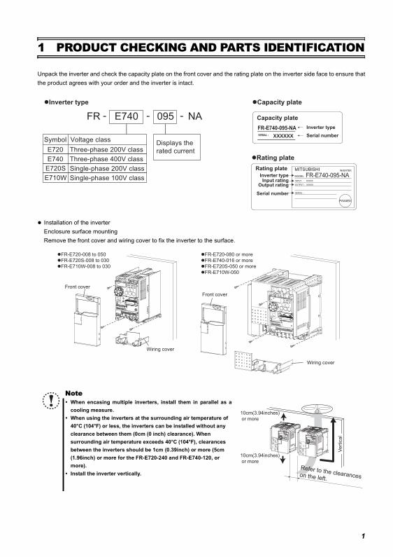
Unpack the inverter and check the capacity plate on the front cover and the rating plate on the inverter side face to ensure thatthe product agrees with your order and the inverter is intact.
Installation of the inverterEnclosure surface mountingRemove the front cover and wiring cover to fix the inverter to the surface.
NoteWhen encasing multiple inverters, install them in parallel as acooling measure.When using the inverters at the surrounding air temperature of 40°C (104°F) or less, the inverters can be installed without any clearance between them (0cm (0 inch) clearance). When surrounding air temperature exceeds 40°C (104°F), clearances between the inverters should be 1cm (0.39inch) or more (5cm (1.96inch) or more for the FR-E720-240 and FR-E740-120, or more).Install the inverter vertically.
FR E740 095
Displays the
rated current
- - - NAInverter type
Serial number
Capacity plate
FR-E740-095-NA
Rating plate
Inverter typeInput rating
Output rating
Serial number
FR-E740-095-NA
Inverter type Capacity plate
Rating plate
Symbol Voltage class
E720
E740
Three-phase 200V class
Three-phase 400V class
Single-phase 200V classE720S
Single-phase 100V classE710W
Front cover
Wiring cover
Front cover
Wiring cover
FR-E720-008 to 050
FR-E720S-008 to 030
FR-E710W-008 to 030
FR-E720-080 or more
FR-E740-016 or more
FR-E720S-050 or more
FR-E710W-050
Vert
ica
l
10cm(3.94inches)
or more
10cm(3.94inches)
or more
Refer to the clearanceson the left.
1
PRODUCT CHECKING AND PARTS IDENTIFICATION
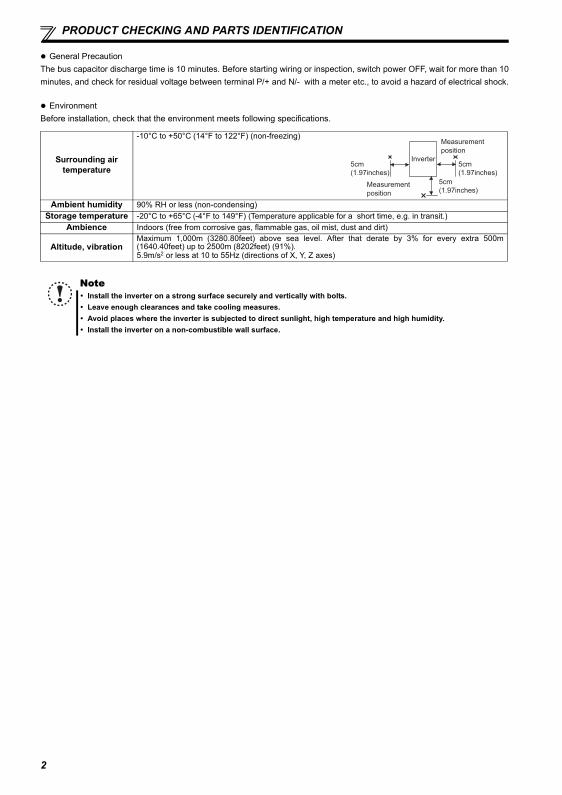
General PrecautionThe bus capacitor discharge time is 10 minutes. Before starting wiring or inspection, switch power OFF, wait for more than 10minutes, and check for residual voltage between terminal P/+ and N/- with a meter etc., to avoid a hazard of electrical shock.
EnvironmentBefore installation, check that the environment meets following specifications.
Surrounding air temperature
-10°C to +50°C (14°F to 122°F) (non-freezing)
Ambient humidity 90% RH or less (non-condensing)Storage temperature -20°C to +65°C (-4°F to 149°F) (Temperature applicable for a short time, e.g. in transit.)
Ambience Indoors (free from corrosive gas, flammable gas, oil mist, dust and dirt)
Altitude, vibrationMaximum 1,000m (3280.80feet) above sea level. After that derate by 3% for every extra 500m(1640.40feet) up to 2500m (8202feet) (91%).5.9m/s2 or less at 10 to 55Hz (directions of X, Y, Z axes)
NoteInstall the inverter on a strong surface securely and vertically with bolts.Leave enough clearances and take cooling measures.Avoid places where the inverter is subjected to direct sunlight, high temperature and high humidity.Install the inverter on a non-combustible wall surface.
5cm
(1.97inches)
5cm
(1.97inches)
5cm
(1.97inches)
Measurement
position
Measurement
position
Inverter
2
3
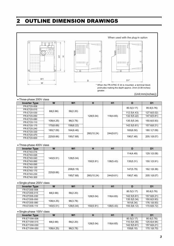
2 OUTLINE DIMENSION DRAWINGS
• Three-phase 200V class
• Three-phase 400V class
• Single-phase 200V class
• Single-phase 100V class
(Unit:mm(inches))
Inverter Type W W1 H H1 D D1FR-E720-008
68(2.68) 56(2.20)
128(5.04) 118(4.65)
80.5(3.17) 95.6(3.76)FR-E720-015FR-E720-030 112.5(4.43) 127.6(5.02)FR-E720-050 132.5(5.22) 147.6(5.81)FR-E720-080 108(4.25) 96(3.78) 135.5(5.34) 150.6(5.93)FR-E720-110FR-E720-175 170(6.69) 158(6.22) 142.5(5.61) 157.6(6.21)FR-E720-240 180(7.09) 164(6.46)
260(10.24) 244(9.61)165(6.50) 180.1(7.09)FR-E720-330
FR-E720-470 220(8.66) 195(7.68) 190(7.48) 205.1(8.07)FR-E720-600
Inverter Type W W1 H H1 D D1FR-E740-016
140(5.51) 128(5.04)150(5.91) 138(5.43)
114(4.49) 129.1(5.08)FR-E740-026FR-E740-040
135(5.31) 150.1(5.91)FR-E740-060FR-E740-095FR-E740-120
220(8.66)208(8.19) 147(5.79) 162.1(6.38)FR-E740-170
FR-E740-230 195(7.68) 260(10.24) 244(9.61) 190(7.48) 205.1(8.07)FR-E740-300
Inverter Type W W1 H H1 D D1FR-E720S-008
68(2.68) 56(2.20)128(5.04) 118(4.65)
80.5(3.17) 95.6(3.76)FR-E720S-015FR-E720S-030 142.5(5.61) 157.6(6.21)FR-E720S-050 108(4.25) 96(3.78) 135.5(5.34) 150.6(5.93)FR-E720S-080 161(6.34) 176.1(6.93)FR-E720S-110 140(5.51) 128(5.04) 150(5.91) 138(5.43) 155.5(6.12) 170.6(6.72)
Inverter Type W W1 H H1 D D1FR-E710W-008
68(2.68) 56(2.20) 128(5.04) 118(4.65)
80.5(3.17) 95.6(3.76)FR-E710W-015 110.5(4.35) 125.6(4.94)FR-E710W-030 142.5(5.61) 157.6(6.21)FR-E710W-050 108(4.25) 96(3.78) 155(6.10) 170.1(6.70)
DW1
W
H1 H
D1*
When used with the plug-in option
* When the FR-A7NC E kit is mounted, a terminal blockprotrudes making the depth approx. 2mm (0.08 inches)greater.
4
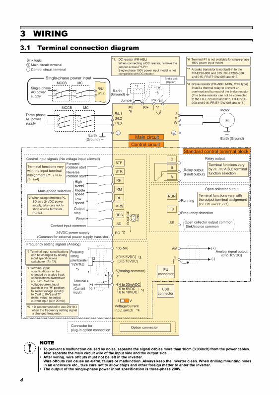
Terminal connection diagram
3 WIRING3.1 Terminal connection diagram
NOTETo prevent a malfunction caused by noise, separate the signal cables more than 10cm (3.93inch) from the power cables. Also separate the main circuit wire of the input side and the output side.After wiring, wire offcuts must not be left in the inverter.Wire offcuts can cause an alarm, failure or malfunction. Always keep the inverter clean. When drilling mounting holesin an enclosure etc., take care not to allow chips and other foreign matter to enter the inverter.The output of the single-phase power input specification is three-phase 200V.
Earth (Ground)
Motor
IM
Earth (Ground)
Three-phase
AC power
supply
MCCB MC
R/L1
P1 P/+
PR N/-
S/L2
T/L3
U
V
W
Earth
(Ground)
*8 Brake resistor (FR-ABR, MRS, MYS type)
Install a thermal relay to prevent an
overheat and burnout of the brake resistor.
(The brake resistor can not be connected
to the FR-E720-008 and 015, FR-E720S-
008 and 015, FR-E710W-008 and 015.)
*7 A brake transistor is not built-in to the
FR-E720-008 and 015, FR-E720S-008
and 015, FR-E710W-008 and 015.
Forward rotation start
Reverse rotation start
Middle speed
High speed
Low speed
Output
stop
Reset
Control input signals (No voltage input allowed)
Contact input common
24VDC power supply
(Common for external power supply transistor)
STR
STF
RH
RM
RL
MRS
SD
PC
Relay output
Running
Frequency detection
Open collector output
Open collector output common
Sink/source common
FU
RUN
SE
A
B
C
AM
5
Frequency setting signals (Analog)
2 0 to 5VDC
10(+5V)
2
3
1
4 4 to 20mADC
Frequency
setting
potentiometer1/2W1kΩ
Terminal 4 input(Current input)
(+)(-)
5(Analog common)
*5 It is recommended to use 2W1kΩ when the frequency setting signal is changed frequently.
*5
Connector for
plug-in option connectionOption connector
*3 Terminal input specifications can be changed by analog input specifications switchover (Pr. 73).
*2 When using terminals PC-
SD as a 24VDC power
supply, take care not to
short across terminals
PC-SD.
PU
connector
USB
connector
Jumper
*1
*8
*7*6
*2
*3
*4
Terminal functions vary
with the input terminal
assignment (Pr. 178 to
Pr. 184)
Multi-speed selection
Terminal functions vary with
the output terminal assignment
(Pr. 190 and Pr. 191)
Terminal functions vary
by Pr. 192 A,B,C terminal
function selection
SIN
K
SO
UR
CE
I V
*4
0 to 5VDC
(0 to 10VDC)
0 to 10VDC
*4 Terminal input specifications can be changed by analog input specifications switchover (Pr. 267). Set the voltage/current input switch in the "V" position to select voltage input (0 to 5V/0 to10V) and "I" (initial value) to select current input (4 to 20mA).
Voltage/current
input switch
Main circuit
Control circuit
Standard control temirnal block
R
RES
Relay output
(Fault output)
Brake unit(Option)
(+)
(-)
Analog signal output(0 to 10VDC)
Single-phase
AC power
supply
MCCB MC
R/L1
S/L2
Single-phase power input
*1. DC reactor (FR-HEL)
When connecting a DC reactor, remove the
jumper across P1-P/+ Single-phase 100V power input model is not compatible with DC reactor.
Control circuit terminal
Main circuit terminal
Sink logic *6 Terminal P1 is not available for single-phase 100V power input model.
Main circuit terminal specifications
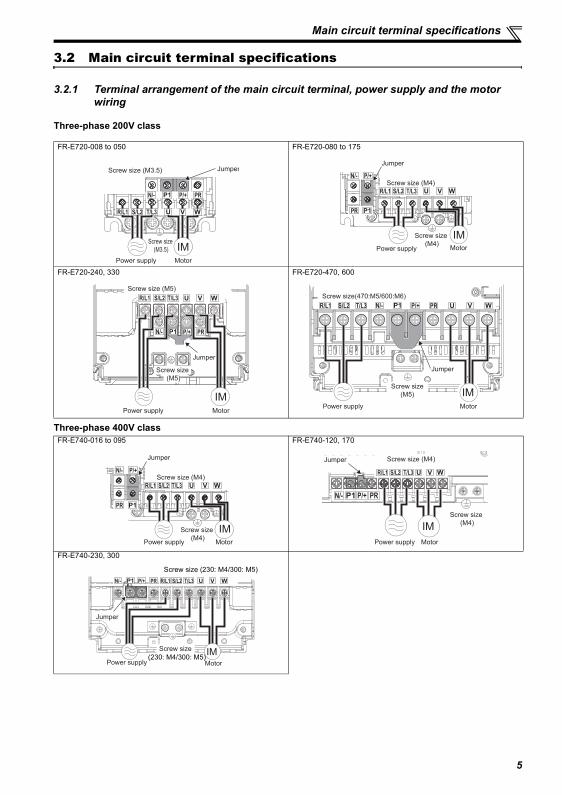
3.2 Main circuit terminal specifications
3.2.1 Terminal arrangement of the main circuit terminal, power supply and the motor wiring
Three-phase 200V class
Three-phase 400V class
FR-E720-008 to 050 FR-E720-080 to 175
FR-E720-240, 330 FR-E720-470, 600
FR-E740-016 to 095 FR-E740-120, 170
FR-E740-230, 300
Screw size (M3.5)
MotorPower supply
N/- P/+ PR
IM
R/L1 S/L2 T/L3
JumperScrew size (M3.5)
Screw size (M4) MotorPower supply
N/- P/+
PR
IM
R/L1 S/L2 T/L3
Jumper
Screw size (M4)
MotorPower supply
IM
N/- P/+ PR
R/L1 S/L2 T/L3
Jumper
Screw size (M5)
Screw size (M5)
N/- P/+ PRR/L1 S/L2 T/L3
Jumper
Screw size(470:M5/600:M6)
Screw size
(M5)
MotorPower supply
IM
N/- P/+
PR
R/L1 S/L2 T/L3
Screw size (M4) MotorPower supply
IM
Jumper
Screw size (M4)
N/- P/+ PR
R/L1 S/L2 T/L3
Screw size (M4)
Screw size (M4)
MotorPower supply
Jumper
IM
MotorPower supply
IM
N/- P/+ PR R/L1 S/L2 T/L3
Jumper
Screw size
(230: M4/300: M5)
Screw size (230: M4/300: M5)
5
Main circuit terminal specifications
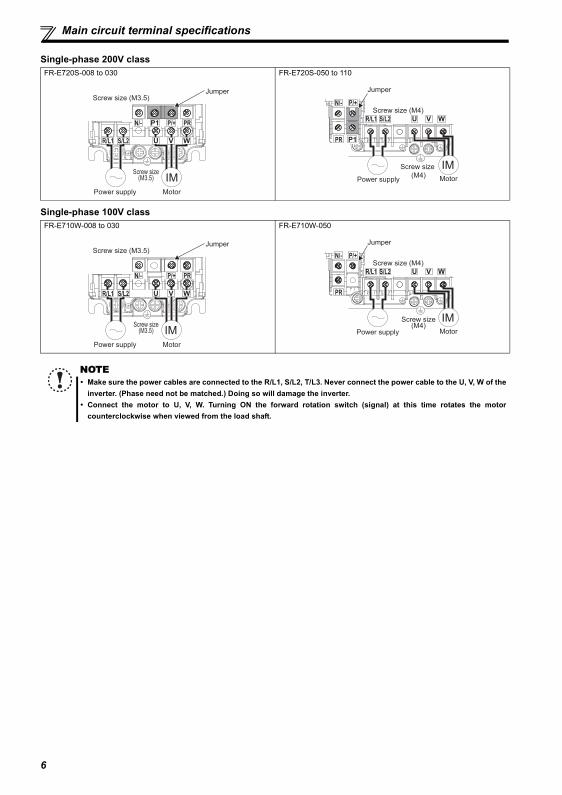
Single-phase 200V class
Single-phase 100V class
FR-E720S-008 to 030 FR-E720S-050 to 110
FR-E710W-008 to 030 FR-E710W-050
NOTEMake sure the power cables are connected to the R/L1, S/L2, T/L3. Never connect the power cable to the U, V, W of theinverter. (Phase need not be matched.) Doing so will damage the inverter.Connect the motor to U, V, W. Turning ON the forward rotation switch (signal) at this time rotates the motorcounterclockwise when viewed from the load shaft.
Screw size (M3.5)
MotorPower supply
N/- P/+ PR
IM
R/L1 S/L2
JumperScrew size (M3.5)
Screw size
(M4)MotorPower supply
N/- P/+
PR
IM
R/L1 S/L2
Jumper
Screw size (M4)
Screw size (M3.5)
MotorPower supply
N/- P/+ PR
IM
R/L1 S/L2
JumperScrew size (M3.5)
Screw size (M4)
MotorPower supply
N/- P/+
PR
IM
R/L1 S/L2
Jumper
Screw size (M4)
6
Main circuit terminal specifications
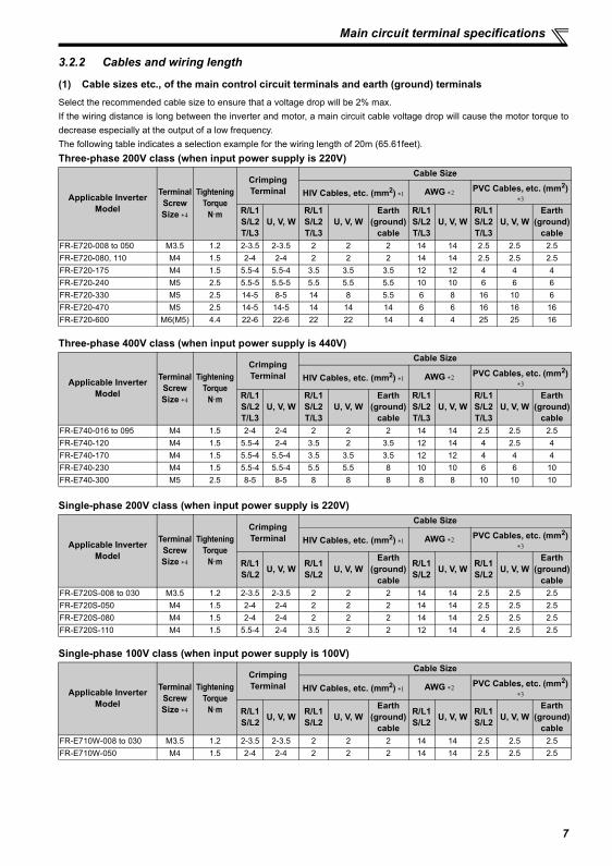
3.2.2 Cables and wiring length
(1) Cable sizes etc., of the main control circuit terminals and earth (ground) terminalsSelect the recommended cable size to ensure that a voltage drop will be 2% max.If the wiring distance is long between the inverter and motor, a main circuit cable voltage drop will cause the motor torque todecrease especially at the output of a low frequency.The following table indicates a selection example for the wiring length of 20m (65.61feet).Three-phase 200V class (when input power supply is 220V)
Three-phase 400V class (when input power supply is 440V)
Single-phase 200V class (when input power supply is 220V)
Single-phase 100V class (when input power supply is 100V)
Applicable InverterModel
Terminal ScrewSize ∗4
TighteningTorque
N·m
Crimping Terminal
Cable Size
HIV Cables, etc. (mm2) ∗1 AWG ∗2 PVC Cables, etc. (mm2) ∗3
R/L1S/L2T/L3
U, V, WR/L1S/L2T/L3
U, V, WEarth
(ground) cable
R/L1S/L2T/L3
U, V, WR/L1S/L2T/L3
U, V, WEarth
(ground) cable
FR-E720-008 to 050 M3.5 1.2 2-3.5 2-3.5 2 2 2 14 14 2.5 2.5 2.5FR-E720-080, 110 M4 1.5 2-4 2-4 2 2 2 14 14 2.5 2.5 2.5FR-E720-175 M4 1.5 5.5-4 5.5-4 3.5 3.5 3.5 12 12 4 4 4FR-E720-240 M5 2.5 5.5-5 5.5-5 5.5 5.5 5.5 10 10 6 6 6FR-E720-330 M5 2.5 14-5 8-5 14 8 5.5 6 8 16 10 6FR-E720-470 M5 2.5 14-5 14-5 14 14 14 6 6 16 16 16FR-E720-600 M6(M5) 4.4 22-6 22-6 22 22 14 4 4 25 25 16
Applicable InverterModel
Terminal ScrewSize ∗4
TighteningTorque
N·m
Crimping Terminal
Cable Size
HIV Cables, etc. (mm2) ∗1 AWG ∗2 PVC Cables, etc. (mm2) ∗3
R/L1S/L2T/L3
U, V, WR/L1S/L2T/L3
U, V, WEarth
(ground) cable
R/L1S/L2T/L3
U, V, WR/L1S/L2T/L3
U, V, WEarth
(ground) cable
FR-E740-016 to 095 M4 1.5 2-4 2-4 2 2 2 14 14 2.5 2.5 2.5FR-E740-120 M4 1.5 5.5-4 2-4 3.5 2 3.5 12 14 4 2.5 4FR-E740-170 M4 1.5 5.5-4 5.5-4 3.5 3.5 3.5 12 12 4 4 4FR-E740-230 M4 1.5 5.5-4 5.5-4 5.5 5.5 8 10 10 6 6 10FR-E740-300 M5 2.5 8-5 8-5 8 8 8 8 8 10 10 10
Applicable InverterModel
Terminal ScrewSize ∗4
TighteningTorque
N·m
Crimping Terminal
Cable Size
HIV Cables, etc. (mm2) ∗1 AWG ∗2 PVC Cables, etc. (mm2) ∗3
R/L1S/L2 U, V, W R/L1
S/L2 U, V, WEarth
(ground) cable
R/L1S/L2 U, V, W R/L1
S/L2 U, V, WEarth
(ground) cable
FR-E720S-008 to 030 M3.5 1.2 2-3.5 2-3.5 2 2 2 14 14 2.5 2.5 2.5FR-E720S-050 M4 1.5 2-4 2-4 2 2 2 14 14 2.5 2.5 2.5FR-E720S-080 M4 1.5 2-4 2-4 2 2 2 14 14 2.5 2.5 2.5FR-E720S-110 M4 1.5 5.5-4 2-4 3.5 2 2 12 14 4 2.5 2.5
Applicable InverterModel
Terminal ScrewSize ∗4
TighteningTorque
N·m
Crimping Terminal
Cable Size
HIV Cables, etc. (mm2) ∗1 AWG ∗2 PVC Cables, etc. (mm2) ∗3
R/L1S/L2 U, V, W R/L1
S/L2 U, V, WEarth
(ground) cable
R/L1S/L2 U, V, W R/L1
S/L2 U, V, WEarth
(ground) cable
FR-E710W-008 to 030 M3.5 1.2 2-3.5 2-3.5 2 2 2 14 14 2.5 2.5 2.5FR-E710W-050 M4 1.5 2-4 2-4 2 2 2 14 14 2.5 2.5 2.5
7
Main circuit terminal specifications
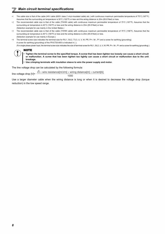
∗1 The cable size is that of the cable (HIV cable (600V class 2 vinyl-insulated cable) etc.) with continuous maximum permissible temperature of 75°C (167°F).Assumes that the surrounding air temperature is 50°C (122°F) or less and the wiring distance is 20m (65.61feet) or less.
∗2 The recommended cable size is that of the cable (THHW cable) with continuous maximum permissible temperature of 75°C (167°F). Assumes that thesurrounding air temperature is 40°C (104°F) or less and the wiring distance is 20m (65.61feet) or less.(Selection example for use mainly in the United States.)
∗3 The recommended cable size is that of the cable (THHW cable) with continuous maximum permissible temperature of 70°C (158°F). Assumes that thesurrounding air temperature is 40°C (104°F) or less and the wiring distance is 20m (65.61feet) or less.(Selection example for use mainly in Europe.)
∗4 The terminal screw size indicates the terminal size for R/L1, S/L2, T/L3, U, V, W, PR, P/+, N/-, P1 and a screw for earthing (grounding).A screw for earthing (grounding) of the FR-E720-600 is indicated in ( ).(For single-phase power input, the terminal screw size indicates the size of terminal screw for R/L1, S/L2, U, V, W, PR, P/+, N/-, P1 and a screw for earthing (grounding).)
The line voltage drop can be calculated by the following formula:
line voltage drop [V]=
Use a larger diameter cable when the wiring distance is long or when it is desired to decrease the voltage drop (torquereduction) in the low speed range.
NOTETighten the terminal screw to the specified torque. A screw that has been tighten too loosely can cause a short circuitor malfunction. A screw that has been tighten too tightly can cause a short circuit or malfunction due to the unitbreakage.Use crimping terminals with insulation sleeve to wire the power supply and motor.
3 × wire resistance[mΩ/m] × wiring distance[m] × current[A]
1000
8
Main circuit terminal specifications
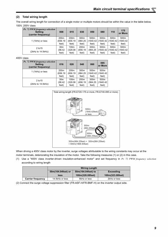
(2) Total wiring lengthThe overall wiring length for connection of a single motor or multiple motors should be within the value in the table below.100V, 200V class
400V class
When driving a 400V class motor by the inverter, surge voltages attributable to the wiring constants may occur at themotor terminals, deteriorating the insulation of the motor. Take the following measures (1) or (2) in this case.(1) Use a "400V class inverter-driven insulation-enhanced motor" and set frequency in Pr. 72 PWM frequency selection
according to wiring length
(2) Connect the surge voltage suppression filter (FR-ASF-H/FR-BMF-H) on the inverter output side.
Pr. 72 PWM frequency selection Setting
(carrier frequency)008 015 030 050 080 110 175
or More
1 (1kHz) or less200m
(656.19feet)
200m(656.19
feet)
300m(984.25
feet)
500m(1640.42
feet)
500m(1640.42
feet)
500m(1640.42
feet)
500m(1640.42
feet)
2 to15(2kHz to 14.5kHz)
30m(98.42feet)
100m(328.08
feet)
200m(656.19
feet)
300m(984.25
feet)
500m(1640.42
feet)
500m(1640.42
feet)
500m(1640.42
feet)
Pr. 72 PWM frequency selection Setting
(carrier frequency)016 026 040 060 095
or More
1 (1kHz) or less 200m(656.19
feet)
200m(656.19
feet)
300m(984.25
feet)
500m(1640.42
feet)
500m(1640.42
feet)
2 to15(2kHz to 14.5kHz)
30m(98.42feet)
100m(328.08
feet)
200m(656.19
feet)
300m(984.25
feet)
500m(1640.42
feet)
Total wiring length (FR-E720-175 or more, FR-E740-095 or more)
Wiring Length50m(164.04feet) or
less50m(164.04feet) to 100m(328.08feet)
Exceeding 100m(323.08feet)
Carrier frequency 14.5kHz or less 8kHz or less 2kHz or less
500m
(1640.42feet)
or less
300m
(984.25feet)
300m
(984.25feet)
300m(984.25feet) + 300m(984.25feet)
= 600m(1968.50feet)
9

Main circuit terminal specifications
NOTEEspecially for long-distance wiring, the inverter may be affected by a charging current caused by the straycapacitances of the wiring, leading to a malfunction of the overcurrent protective function, fast response current limitfunction, or stall prevention function or a malfunction or fault of the equipment connected on the inverter output side.If malfunction of fast-response current limit function occurs, disable this function. If malfunction of stall prevention
function occurs, increase the stall level. ( Refer to Pr. 22 Stall prevention operation level and Pr. 156 Stall preventionoperation selection in the chater 4 of the Instruction Manual)
Refer to the chater 4 of the Instrunction Manual for details of Pr. 72 PWM frequency selection . Refer to the manual of theoption for details of surge voltage suppression filter (FR-ASF-H/FR-BMF-H).When using the automatic restart after instantaneous power failure function with wiring length exceeding than 100m,
select without frequency search (Pr. 162 = "1, 11"). ( Refer to the chater 4 of the Instruction Manual)
10
Control circuit specifications
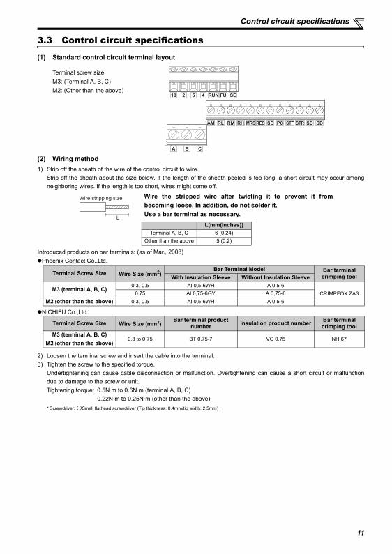
3.3 Control circuit specifications
(1) Standard control circuit terminal layout
(2) Wiring method1) Strip off the sheath of the wire of the control circuit to wire.
Strip off the sheath about the size below. If the length of the sheath peeled is too long, a short circuit may occur amongneighboring wires. If the length is too short, wires might come off.
Introduced products on bar terminals: (as of Mar., 2008)Phoenix Contact Co.,Ltd.
NICHIFU Co.,Ltd.
2) Loosen the terminal screw and insert the cable into the terminal.3) Tighten the screw to the specified torque.
Undertightening can cause cable disconnection or malfunction. Overtightening can cause a short circuit or malfunctiondue to damage to the screw or unit.Tightening torque: 0.5N·m to 0.6N·m (terminal A, B, C)
0.22N·m to 0.25N·m (other than the above)* Screwdriver: Small flathead screwdriver (Tip thickness: 0.4mm/tip width: 2.5mm)
Terminal screw sizeM3: (Terminal A, B, C)M2: (Other than the above)
Wire the stripped wire after twisting it to prevent it frombecoming loose. In addition, do not solder it.Use a bar terminal as necessary.
L(mm(inches))Terminal A, B, C 6 (0.24)
Other than the above 5 (0.2)
Terminal Screw Size Wire Size (mm2)Bar Terminal Model Bar terminal
crimping toolWith Insulation Sleeve Without Insulation Sleeve
M3 (terminal A, B, C)0.3, 0.5 AI 0,5-6WH A 0,5-6
CRIMPFOX ZA30.75 AI 0,75-6GY A 0,75-6M2 (other than the above) 0.3, 0.5 AI 0,5-6WH A 0,5-6
Terminal Screw Size Wire Size (mm2)Bar terminal product
number Insulation product number Bar terminalcrimping tool
M3 (terminal A, B, C)M2 (other than the above)
0.3 to 0.75 BT 0.75-7 VC 0.75 NH 67
SDSDSTF STRPCSDRESMRSRHRMRLAM
CBA
10 2 5 4 RUN FU SE
Wire stripping size
L
11
Control circuit specifications
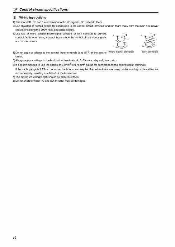
(3) Wiring instructions1) Terminals SD, SE and 5 are common to the I/O signals. Do not earth them.2) Use shielded or twisted cables for connection to the control circuit terminals and run them away from the main and power
circuits (including the 200V relay sequence circuit).3) Use two or more parallel micro-signal contacts or twin contacts to prevent
contact faults when using contact inputs since the control circuit input signalsare micro-currents.
4) Do not apply a voltage to the contact input terminals (e.g. STF) of the controlcircuit.
5) Always apply a voltage to the fault output terminals (A, B, C) via a relay coil, lamp, etc.
6) It is recommended to use the cables of 0.3mm2 to 0.75mm2 gauge for connection to the control circuit terminals.
If the cable gauge is 1.25mm2 or more, the front cover may be lifted when there are many cables running or the cables arerun improperly, resulting in a fall off of the front cover.
7) The maximum wiring length should be 30m(98.43feet).8) Do not short terminal PC and SD. Inverter may be damaged.
Micro signal contacts Twin contacts
12
PRECAUTIONS FOR USE OF THE INVERTER
4 PRECAUTIONS FOR USE OF THE INVERTER
The FR-E700 series is a highly reliable product, but incorrect peripheral circuit making or operation/handling method mayshorten the product life or damage the product.Before starting operation, always recheck the following items.
(1) Use crimping terminals with insulation sleeve to wire the power supply and motor.(2) Application of power to the output terminals (U, V, W) of the inverter will damage the inverter. Never perform such wiring.(3) After wiring, wire offcuts must not be left in the inverter.
Wire offcuts can cause an alarm, failure or malfunction. Always keep the inverter clean.When drilling mounting holes in an enclosure etc., take care not to allow chips and other foreign matter to enter theinverter.
(4) Use cables of the size to make a voltage drop 2% maximum.If the wiring distance is long between the inverter and motor, a main circuit cable voltage drop will cause the motor torqueto decrease especially at the output of a low frequency.Refer to page 7 for the recommended wire sizes.
(5) The overall wiring length should be 500m(1640.42feet) maximum.Especially for long distance wiring, the fast-response current limit function may decrease or the equipment connected tothe secondary side may malfunction or become faulty under the influence of a charging current due to the stray capacityof the wiring. Therefore, note the overall wiring length.
(6) Electromagnetic wave interferenceThe input/output (main circuit) of the inverter includes high frequency components, which may interfere with thecommunication devices (such as AM radios) used near the inverter. In this case, install the FR-BIF optional capacitortype filter (for use in the input side only) or FR-BSF01 common mode filter to minimize interference.
(7) Do not install a power factor correction capacitor, surge suppressor or capacitor type filter on the inverter output side.This will cause the inverter to trip or the capacitor and surge suppressor to be damaged. If any of the above devices areconnected, immediately remove them. (When using capacitor type filter (FR-BIF) for single-phase power supplyspecification, make sure of secure insulation of T/L3-phase, and connect to the input side of the inverter.)
(8) For some short time after the power is switched OFF, a high voltage remains in the smoothing capacitor. Whenaccessing the inverter for inspection, wait for at least 10 minutes after the power supply has been switched OFF, andthen make sure that the voltage across the main circuit terminals P/+ and N/- of the inverter is not more than 30VDCusing a tester, etc. The capacitor is charged with high voltage for some time after power off and it is dangerous.
(9) A short circuit or earth (ground) fault on the inverter output side may damage the inverter modules.Fully check the insulation resistance of the circuit prior to inverter operation since repeated short circuits caused byperipheral circuit inadequacy or an earth (ground) fault caused by wiring inadequacy or reduced motor insulationresistance may damage the inverter modules.Fully check the to-earth (ground) insulation and phase to phase insulation of the inverter output side before power-on.Especially for an old motor or use in hostile atmosphere, securely check the motor insulation resistance etc.
(10) Do not use the inverter input side magnetic contactor to start/stop the inverter.Always use the start signal (turn ON/OFF of STF, STR signal) to start/stop the inverter.
(11) Across P/+ and PR terminals, connect only an external regenerative brake discharging resistor.Do not connect a mechanical brake.The brake resistor can not be connected to the FR-E720-008 or 015, FR-E720S-008 or 015, FR-E710W-008 or 015.Leave terminals P/+ and PR open.Also, never short between these terminals.
13
PRECAUTIONS FOR USE OF THE INVERTER
(12) Do not apply a voltage higher than the permissible voltage to the inverter I/O signal circuits.Application of a voltage higher than the permissible voltage to the inverter I/O signal circuits or opposite polarity maydamage the I/O devices. Especially check the wiring to prevent the speed setting potentiometer from being connectedincorrectly to short terminals 10-5.
(14) If the machine must not be restarted when power is restored after a power failure, provide a magnetic contactor in theinverter's input side and also make up a sequence which will not switch ON the start signal.If the start signal (start switch) remains ON after a power failure, the inverter will automatically restart as soon as thepower is restored.
(15) Instructions for overload operationWhen performing operation of frequent start/stop of the inverter, rise/fall in the temperature of the transistor element ofthe inverter will repeat due to a repeated flow of large current, shortening the life from thermal fatigue. Since thermalfatigue is related to the amount of current, the life can be increased by reducing current at locked condition, startingcurrent, etc. Decreasing current may increase the life. However, decreasing current will result in insufficient torque andthe inverter may not start. Therefore, choose the inverter which has enough allowance for current (up to 2 rank larger incapacity).
(16) Make sure that the specifications and rating match the system requirements.(17) When the motor speed is unstable, due to change in the frequency setting signal caused by electromagnetic noises from
the inverter, take the following measures while applying the motor speed by the analog signal. Do not run the signal cables and power cables (inverter I/O cables) in parallel with each other and do not bundle them. Run signal cables as far away as possible from power cables (inverter I/O cables). Use shield cables as signal cables. Install a ferrite core on the signal cable (Example: ZCAT3035-1330 TDK).
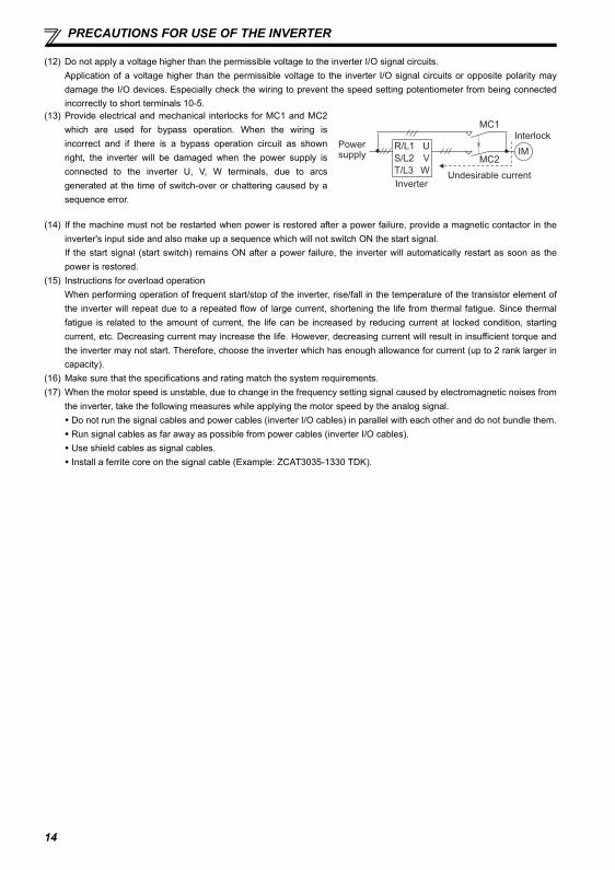
(13) Provide electrical and mechanical interlocks for MC1 and MC2which are used for bypass operation. When the wiring isincorrect and if there is a bypass operation circuit as shownright, the inverter will be damaged when the power supply isconnected to the inverter U, V, W terminals, due to arcsgenerated at the time of switch-over or chattering caused by asequence error.
Power supply
InverterUndesirable current
MC2
MC1
InterlockU
V
W
R/L1
S/L2
T/L3
IM
14
15
FAILSAFE OF THE SYSTEM WHICH USES THE INVERTER
5 FAILSAFE OF THE SYSTEM WHICH USES THE INVERTER
When a fault occurs, the inverter trips to output a fault signal. However, a fault output signal may not be output at an inverterfault occurrence when the detection circuit or output circuit fails, etc. Although Mitsubishi assures best quality products,provide an interlock which uses inverter status output signals to prevent accidents such as damage to machine when theinverter fails for some reason and at the same time consider the system configuration where failsafe from outside the inverter,without using the inverter, is enabled even if the inverter fails.
(1) Interlock method which uses the inverter status output signals By combining the inverter status output signals to provide an interlock as shown below, an inverter alarm can bedetected.
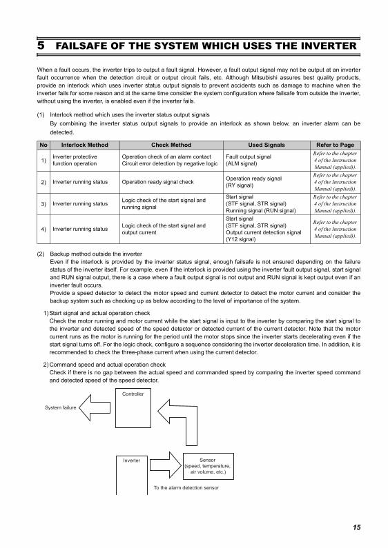
(2) Backup method outside the inverterEven if the interlock is provided by the inverter status signal, enough failsafe is not ensured depending on the failurestatus of the inverter itself. For example, even if the interlock is provided using the inverter fault output signal, start signaland RUN signal output, there is a case where a fault output signal is not output and RUN signal is kept output even if aninverter fault occurs.Provide a speed detector to detect the motor speed and current detector to detect the motor current and consider thebackup system such as checking up as below according to the level of importance of the system.
1) Start signal and actual operation checkCheck the motor running and motor current while the start signal is input to the inverter by comparing the start signal tothe inverter and detected speed of the speed detector or detected current of the current detector. Note that the motorcurrent runs as the motor is running for the period until the motor stops since the inverter starts decelerating even if thestart signal turns off. For the logic check, configure a sequence considering the inverter deceleration time. In addition, it isrecommended to check the three-phase current when using the current detector.
2) Command speed and actual operation checkCheck if there is no gap between the actual speed and commanded speed by comparing the inverter speed commandand detected speed of the speed detector.
No Interlock Method Check Method Used Signals Refer to Page
1)Inverter protective function operation
Operation check of an alarm contactCircuit error detection by negative logic
Fault output signal (ALM signal)
Refer to the chapter 4 of the Instruction Manual (applied)).
2) Inverter running status Operation ready signal check Operation ready signal (RY signal)
Refer to the chapter 4 of the Instruction Manual (applied)).
3) Inverter running status Logic check of the start signal and running signal
Start signal (STF signal, STR signal)Running signal (RUN signal)
Refer to the chapter 4 of the Instruction Manual (applied)).
4) Inverter running status Logic check of the start signal and output current
Start signal (STF signal, STR signal)Output current detection signal (Y12 signal)
Refer to the chapter 4 of the Instruction Manual (applied)).
Inverter
Controller
System failure
To the alarm detection sensor
Sensor
(speed, temperature,
air volume, etc.)
PARAMETER LIST
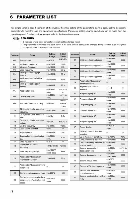
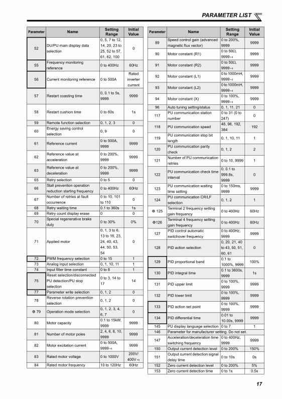
6 PARAMETER LIST
For simple variable-speed operation of the inverter, the initial setting of the parameters may be used. Set the necessaryparameters to meet the load and operational specifications. Parameter setting, change and check can be made from theoperation panel. For details of parameters, refer to the instruction manual.
REMARKS indicates simple mode parameters. (initially set to extended mode)
The parameters surrounded by a black border in the table allow its setting to be changed during operation even if "0" (initialvalue) is set in Pr. 77 Parameter write selection.
Parameter Name Setting Range
Initial Value
0 Torque boost 0 to 30% 6/4/3/2% ∗1
1 Maximum frequency 0 to 120Hz 120Hz 2 Minimum frequency 0 to 120Hz 0Hz 3 Base frequency 0 to 400Hz 60Hz
4Multi-speed setting (high speed)
0 to 400Hz 60Hz
5Multi-speed setting (middle speed)
0 to 400Hz 30Hz
6Multi-speed setting (low speed)
0 to 400Hz 10Hz
7 Acceleration time0 to 3600/360s
5/10/15s
∗2
8 Deceleration time0 to 3600/360s
5/10/15s
∗2
9 Electronic thermal O/L relay 0 to 500ARated
inverter current
10DC injection brake operation frequency
0 to 120Hz 3Hz
11DC injection brake operation time
0 to 10s 0.5s
12DC injection brake operation voltage
0 to 30% 6/4/2% ∗3
13 Starting frequency 0 to 60Hz 0.5Hz14 Load pattern selection 0 to 3 0
15 Jog frequency 0 to 400Hz 5Hz
16Jog acceleration/deceleration time
0 to 3600/360s
0.5s
17 MRS input selection 0, 2, 4 0
18High speed maximum frequency
120 to 400Hz 120Hz
19 Base frequency voltage0 to 1000V, 8888, 9999
9999
20Acceleration/deceleration reference frequency
1 to 400Hz 60Hz
21Acceleration/deceleration time increments
0, 1 0
22 Stall prevention operation level 0 to 200% 150%
23Stall prevention operation level compensation factor at double speed
0 to 200%, 9999
9999
24 Multi-speed setting (speed 4)0 to 400Hz, 9999
9999
25 Multi-speed setting (speed 5)0 to 400Hz, 9999
9999
26 Multi-speed setting (speed 6)0 to 400Hz, 9999
9999
27 Multi-speed setting (speed 7)0 to 400Hz, 9999
9999
29Acceleration/deceleration pattern selection
0, 1, 2 0
30Regenerative function selection
0, 1, 2 0
31 Frequency jump 1A0 to 400Hz, 9999
9999
32 Frequency jump 1B0 to 400Hz, 9999
9999
33 Frequency jump 2A0 to 400Hz, 9999
9999
34 Frequency jump 2B0 to 400Hz, 9999
9999
35 Frequency jump 3A0 to 400Hz, 9999
9999
36 Frequency jump 3B0 to 400Hz, 9999
9999
37 Speed display0, 0.01 to 9998
0
40RUN key rotation direction selection
0, 1 0
41 Up-to-frequency sensitivity 0 to 100% 10%42 Output frequency detection 0 to 400Hz 6Hz
43Output frequency detection for reverse rotation
0 to 400Hz, 9999
9999
44Second acceleration/deceleration time
0 to 3600/360s
5/10/15s
∗2
45 Second deceleration time0 to 3600/360s, 9999
9999
46 Second torque boost0 to 30%, 9999
9999
47 Second V/F (base frequency)0 to 400Hz, 9999
9999
48Second stall prevention operation current
0 to 200%, 9999
9999
51Second electronic thermal O/L relay
0 to 500A, 9999
9999
Parameter Name Setting Range
Initial Value
16
PARAMETER LIST
52DU/PU main display data selection
0, 5, 7 to 12, 14, 20, 23 to 25, 52 to 57, 61, 62, 100
0
55Frequency monitoring reference
0 to 400Hz 60Hz
56 Current monitoring reference 0 to 500ARated
inverter current
57 Restart coasting time0, 0.1 to 5s, 9999
9999
58 Restart cushion time 0 to 60s 1s
59 Remote function selection 0, 1, 2, 3 0
60Energy saving control selection
0, 9 0
61 Reference current0 to 500A, 9999
9999
62Reference value at acceleration
0 to 200%, 9999
9999
63Reference value at deceleration
0 to 200%, 9999
9999
65 Retry selection 0 to 5 0
66Stall prevention operation reduction starting frequency
0 to 400Hz 60Hz
67Number of retries at fault occurrence
0 to 10, 101 to 110
0
68 Retry waiting time 0.1 to 360s 1s69 Retry count display erase 0 0
70Special regenerative brake duty
0 to 30% 0%
71 Applied motor
0, 1, 3 to 6, 13 to 16, 23, 24, 40, 43, 44, 50, 53, 54
0
72 PWM frequency selection 0 to 15 173 Analog input selection 0, 1, 10, 11 174 Input filter time constant 0 to 8 1
75Reset selection/disconnected PU detection/PU stop selection
0 to 3, 14 to 17
14
77 Parameter write selection 0, 1, 2 0
78Reverse rotation prevention selection
0, 1, 2 0
79 Operation mode selection0, 1, 2, 3, 4, 6, 7
0
80 Motor capacity0.1 to 15kW, 9999
9999
81 Number of motor poles2, 4, 6, 8, 10, 9999
9999
82 Motor excitation current0 to 500A, 9999 ∗4
9999
83 Rated motor voltage 0 to 1000V200V/
400V ∗6
84 Rated motor frequency 10 to 120Hz 60Hz
Parameter Name Setting Range
Initial Value
89Speed control gain (advanced magnetic flux vector)
0 to 200%, 9999
9999
90 Motor constant (R1)0 to 50Ω, 9999 ∗4
9999
91 Motor constant (R2)0 to 50Ω, 9999 ∗4
9999
92 Motor constant (L1)0 to 1000mH, 9999 ∗4
9999
93 Motor constant (L2)0 to 1000mH, 9999 ∗4
9999
94 Motor constant (X)0 to 100%, 9999 ∗4
9999
96 Auto tuning setting/status 0, 1, 11, 21 0
117PU communication station number
0 to 31 (0 to 247)
0
118 PU communication speed48, 96, 192, 384
192
119PU communication stop bit length
0, 1, 10, 11 1
120PU communication parity check
0, 1, 2 2
121Number of PU communication retries
0 to 10, 9999 1
122PU communication check time interval
0, 0.1 to 999.8s, 9999
0
123PU communication waiting time setting
0 to 150ms, 9999
9999
124PU communication CR/LF selection
0, 1, 2 1
125Terminal 2 frequency setting gain frequency
0 to 400Hz 60Hz
126Terminal 4 frequency setting gain frequency
0 to 400Hz 60Hz
127PID control automatic switchover frequency
0 to 400Hz, 9999
9999
128 PID action selection0, 20, 21, 40 to 43, 50, 51, 60, 61
0
129 PID proportional band0.1 to 1000%, 9999
100%
130 PID integral time0.1 to 3600s, 9999
1s
131 PID upper limit0 to 100%, 9999
9999
132 PID lower limit0 to 100%, 9999
9999
133 PID action set point0 to 100%, 9999
9999
134 PID differential time0.01 to 10.00s, 9999
9999
145 PU display language selection 0 to 7 1146 Parameter for manufacturer setting. Do not set.
147Acceleration/deceleration time switching frequency
0 to 400Hz, 9999
9999
150 Output current detection level 0 to 200% 150%
151Output current detection signal delay time
0 to 10s 0s
152 Zero current detection level 0 to 200% 5%153 Zero current detection time 0 to 1s 0.5s
Parameter Name Setting Range
Initial Value
17
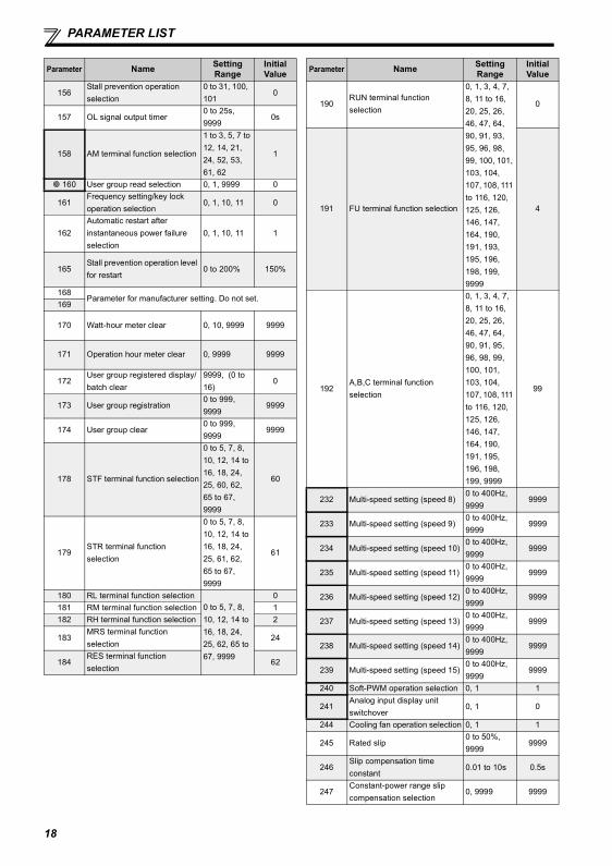
PARAMETER LIST
156Stall prevention operation selection
0 to 31, 100, 101
0
157 OL signal output timer0 to 25s, 9999
0s
158 AM terminal function selection
1 to 3, 5, 7 to 12, 14, 21, 24, 52, 53, 61, 62
1
160 User group read selection 0, 1, 9999 0
161Frequency setting/key lock operation selection
0, 1, 10, 11 0
162Automatic restart after instantaneous power failure selection
0, 1, 10, 11 1
165Stall prevention operation level for restart
0 to 200% 150%
168Parameter for manufacturer setting. Do not set.
169
170 Watt-hour meter clear 0, 10, 9999 9999
171 Operation hour meter clear 0, 9999 9999
172User group registered display/batch clear
9999, (0 to 16)
0
173 User group registration0 to 999, 9999
9999
174 User group clear0 to 999, 9999
9999
178 STF terminal function selection
0 to 5, 7, 8, 10, 12, 14 to 16, 18, 24, 25, 60, 62, 65 to 67, 9999
60
179STR terminal function selection
0 to 5, 7, 8, 10, 12, 14 to 16, 18, 24, 25, 61, 62, 65 to 67, 9999
61
180 RL terminal function selection0 to 5, 7, 8, 10, 12, 14 to 16, 18, 24, 25, 62, 65 to 67, 9999
0181 RM terminal function selection 1182 RH terminal function selection 2
183MRS terminal function selection
24
184RES terminal function selection
62
Parameter Name Setting Range
Initial Value
190RUN terminal function selection
0, 1, 3, 4, 7, 8, 11 to 16, 20, 25, 26, 46, 47, 64, 90, 91, 93, 95, 96, 98, 99, 100, 101, 103, 104, 107, 108, 111 to 116, 120, 125, 126, 146, 147, 164, 190, 191, 193, 195, 196, 198, 199, 9999
0
191 FU terminal function selection 4
192A,B,C terminal function selection
0, 1, 3, 4, 7, 8, 11 to 16, 20, 25, 26, 46, 47, 64, 90, 91, 95, 96, 98, 99, 100, 101, 103, 104, 107, 108, 111 to 116, 120, 125, 126, 146, 147, 164, 190, 191, 195, 196, 198, 199, 9999
99
232 Multi-speed setting (speed 8)0 to 400Hz, 9999
9999
233 Multi-speed setting (speed 9)0 to 400Hz, 9999
9999
234 Multi-speed setting (speed 10)0 to 400Hz, 9999
9999
235 Multi-speed setting (speed 11)0 to 400Hz, 9999
9999
236 Multi-speed setting (speed 12)0 to 400Hz, 9999
9999
237 Multi-speed setting (speed 13)0 to 400Hz, 9999
9999
238 Multi-speed setting (speed 14)0 to 400Hz, 9999
9999
239 Multi-speed setting (speed 15)0 to 400Hz, 9999
9999
240 Soft-PWM operation selection 0, 1 1
241Analog input display unit switchover
0, 1 0
244 Cooling fan operation selection 0, 1 1
245 Rated slip0 to 50%, 9999
9999
246Slip compensation time constant
0.01 to 10s 0.5s
247Constant-power range slip compensation selection
0, 9999 9999
Parameter Name Setting Range
Initial Value
18
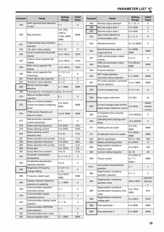
PARAMETER LIST
249Earth (ground) fault detection at start
0, 1 0
250 Stop selection
0 to 100s, 1000 to 1100s, 8888, 9999
9999
251Output phase loss protection selection
0, 1 1
255 Life alarm status display (0 to 15) 0
256Inrush current limit circuit life display
(0 to 100%) 100%
257Control circuit capacitor life display
(0 to 100%) 100%
258Main circuit capacitor life display
(0 to 100%) 100%
259Main circuit capacitor life measuring
0, 1 (2, 3, 8, 9)
0
261 Power failure stop selection 0, 1, 2 0267 Terminal 4 input selection 0, 1, 2 0
268Monitor decimal digits selection
0, 1, 9999 9999
269 Parameter for manufacturer setting. Do not set.
270Stop-on contact control selection
0, 1 0
275Stop-on contact excitation current low-speed multiplying factor
0 to 300%, 9999
9999
276PWM carrier frequency at stop-on contact
0 to 9, 9999 9999
277Stall prevention operation current switchover
0, 1 0
278 Brake opening frequency 0 to 30Hz 3Hz279 Brake opening current 0 to 200% 130%
280Brake opening current detection time
0 to 2s 0.3s
281 Brake operation time at start 0 to 5s 0.3s282 Brake operation frequency 0 to 30Hz 6Hz283 Brake operation time at stop 0 to 5s 0.3s286 Droop gain 0 to 100% 0%287 Droop filter time constant 0 to 1s 0.3s
292Automatic acceleration/deceleration
0, 1, 7, 8, 11 0
293Acceleration/deceleration separate selection
0 to 2 0
295Magnitude of frequency change setting
0, 0.01, 0.1, 1, 10
0
298 Frequency search gain0 to 32767, 9999
9999
299Rotation direction detection selection at restarting
0, 1, 9999 0
338Communication operation command source
0, 1 0
339Communication speed command source
0, 1, 2 0
340Communication startup mode selection
0, 1, 10 0
342Communication EEPROM write selection
0, 1 0
343 Communication error count — 0450 Second applied motor 0, 1, 9999 9999
Parameter Name Setting Range
Initial Value
495 Remote output selection 0, 1, 10, 11 0
496 Remote output data 1 0 to 4095 0
497 Remote output data 2 0 to 4095 0
502Stop mode selection at communication error
0, 1, 2, 3 0
503 Maintenance timer 0 (1 to 9998) 0
504Maintenance timer alarm output set time
0 to 9998, 9999
9999
547USB communication station number
0 to 31 0
548USB communication check time interval
0 to 999.8s, 9999
9999
549 Protocol selection 0, 1 0
550NET mode operation command source selection
0, 2, 9999 9999
551PU mode operation command source selection
2 to 4, 9999 9999
555 Current average time 0.1 to 1.0s 1s
556 Data output mask time 0 to 20s 0s
557Current average value monitor signal output reference current
0 to 500ARated
inverter current
563Energization time carrying-over times
(0 to 65535) 0
564Operating time carrying-over times
(0 to 65535) 0
571 Holding time at a start0 to 10s, 9999
9999
611 Acceleration time at a restart0 to 3600s, 9999
9999
645 AM 0V adjustment 970 to 1200 1000653 Speed smoothing control 0 to 200% 0
665Regeneration avoidance frequency gain
0 to 200% 100
800 Control method selection 20, 30 20
859 Torque current0 to 500A (0 to ****) , 9999 ∗4
9999
872 ∗7Input phase loss protection selection
0, 1 1
882Regeneration avoidance operation selection
0, 1, 2 0
883Regeneration avoidance operation level
300 to 800V400VDC/780VDC
∗6
885Regeneration avoidance compensation frequency limit value
0 to 10Hz, 9999
6Hz
886Regeneration avoidance voltage gain
0 to 200% 100%
888 Free parameter 1 0 to 9999 9999
889 Free parameter 2 0 to 9999 9999
Parameter Name Setting Range
Initial Value
19
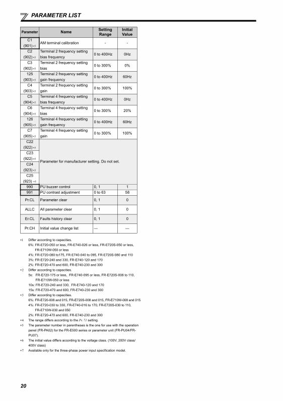
PARAMETER LIST
C1(901) ∗5
AM terminal calibration - -
C2(902) ∗5
Terminal 2 frequency setting bias frequency
0 to 400Hz 0Hz
C3(902) ∗5
Terminal 2 frequency setting bias
0 to 300% 0%
125(903) ∗5
Terminal 2 frequency setting gain frequency
0 to 400Hz 60Hz
C4(903) ∗5
Terminal 2 frequency setting gain
0 to 300% 100%
C5(904) ∗5
Terminal 4 frequency setting bias frequency
0 to 400Hz 0Hz
C6(904) ∗5
Terminal 4 frequency setting bias
0 to 300% 20%
126(905) ∗5
Terminal 4 frequency setting gain frequency
0 to 400Hz 60Hz
C7(905) ∗5
Terminal 4 frequency setting gain
0 to 300% 100%
C22
(922) ∗5
Parameter for manufacturer setting. Do not set.
C23
(922) ∗5
C24
(923) ∗5
C25(923) ∗5
990 PU buzzer control 0, 1 1991 PU contrast adjustment 0 to 63 58
Pr.CL Parameter clear 0, 1 0
ALLC All parameter clear 0, 1 0
Er.CL Faults history clear 0, 1 0
Pr.CH Initial value change list — —
∗1 Differ according to capacities.6%: FR-E720-050 or less, FR-E740-026 or less, FR-E720S-050 or less,
FR-E710W-050 or less4%: FR-E720-080 to175, FR-E740-040 to 095, FR-E720S-080 and 1103%: FR-E720-240 and 330, FR-E740-120 and 1702%: FR-E720-470 and 600, FR-E740-230 and 300
∗2 Differ according to capacities. 5s: FR-E720-175 or less, FR-E740-095 or less, FR-E720S-008 to 110,
FR-E710W-050 or less10s: FR-E720-240 and 330, FR-E740-120 and 17015s: FR-E720-470 and 600, FR-E740-230 and 300
∗3 Differ according to capacities.6%: FR-E720-008 and 015, FR-E720S-008 and 015, FR-E710W-008 and 0154%: FR-E720-030 to 330, FR-E740-016 to 170, FR-E720S-030 to 110,
FR-E710W-030 and 0502%: FR-E720-470 and 600, FR-E740-230 and 300
∗4 The range differs according to the Pr. 71 setting.∗5 The parameter number in parentheses is the one for use with the operation
panel (FR-PA02) for the FR-E500 series or parameter unit (FR-PU04/FR-PU07).
∗6 The initial value differs according to the voltage class. (100V, 200V class/400V class)
∗7 Available only for the three-phase power input specification model.
Parameter Name Setting Range
Initial Value
20
Reset method of protective function
7 TROUBLESHOOTING
When a fault occurs in the inverter, the inverter trips and the PU display automatically changes to any of the following fault oralarm indications.If the fault does not correspond to any of the following faults or if you have any other problem, please contact your salesrepresentative.
Retention of fault output signal ...When the magnetic contactor (MC) provided on the input side of the inverter is openedwhen a fault occurs, the inverter's control power will be lost and the fault output will not beheld.
Fault or alarm indication...........When a fault or alarm occurs, the operation panel display automatically switches to the faultor alarm indication.
Resetting method.....................When a fault occurs, the inverter output is kept stopped. Unless reset, therefore, the invertercannot restart.
When any fault occurs, take the appropriate corrective action, then reset the inverter, and resume operation.Not doing so may lead to the inverter fault and damage.
Inverter fault or alarm indications are roughly divided as below.(1) Error message
A message regarding operational fault and setting fault by the operation panel and parameter unit (FR-PU04 /FR-PU07)is displayed. The inverter does not trip.
(2) WarningsThe inverter does not trip even when a warning is displayed. However, failure to take appropriate measures will lead to afault.
(3) AlarmThe inverter does not trip. You can also output an alarm signal by making parameter setting.
(4) FaultWhen a fault occurs, the inverter trips and a fault signal is output.
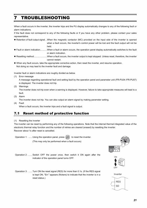
7.1 Reset method of protective function
(1) Resetting the inverterThe inverter can be reset by performing any of the following operations. Note that the internal thermal integrated value of theelectronic thermal relay function and the number of retries are cleared (erased) by resetting the inverter.Recover about 1s after reset is cancelled.
Operation 1: ...... Using the operation panel, press to reset the inverter.
(This may only be performed when a fault occurs)
Operation 2: ....... Switch OFF the power once, then switch it ON again after theindicator of the operation panel turns OFF.
Operation 3: . ..... Turn ON the reset signal (RES) for more than 0.1s. (If the RES signalis kept ON, "Err." appears (flickers) to indicate that the inverter is in areset status.)
ON
OFF
SD
Inverter
RES
21
List of fault or alarm indications
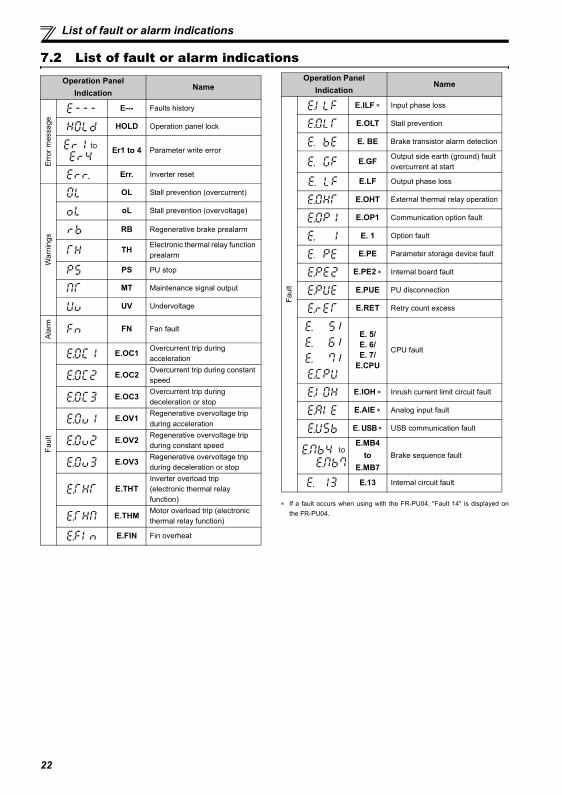
7.2 List of fault or alarm indications
∗ If a fault occurs when using with the FR-PU04, "Fault 14" is displayed onthe FR-PU04.
Operation Panel Indication
Name
Erro
r mes
sage
E--- Faults history
HOLD Operation panel lock
Er1 to 4 Parameter write error
Err. Inverter reset
War
ning
s
OL Stall prevention (overcurrent)
oL Stall prevention (overvoltage)
RB Regenerative brake prealarm
TH Electronic thermal relay function prealarm
PS PU stop
MT Maintenance signal output
UV Undervoltage
Ala
rm FN Fan fault
Faul
t
E.OC1 Overcurrent trip during acceleration
E.OC2 Overcurrent trip during constant speed
E.OC3 Overcurrent trip during deceleration or stop
E.OV1 Regenerative overvoltage trip during acceleration
E.OV2 Regenerative overvoltage trip during constant speed
E.OV3 Regenerative overvoltage trip during deceleration or stop
E.THTInverter overload trip (electronic thermal relay function)
E.THM Motor overload trip (electronic thermal relay function)
E.FIN Fin overheat
to
Faul
t
E.ILF ∗ Input phase loss
E.OLT Stall prevention
E. BE Brake transistor alarm detection
E.GF Output side earth (ground) fault overcurrent at start
E.LF Output phase loss
E.OHT External thermal relay operation
E.OP1 Communication option fault
E. 1 Option fault
E.PE Parameter storage device fault
E.PE2 ∗ Internal board fault
E.PUE PU disconnection
E.RET Retry count excess
/ / /
E. 5/E. 6/E. 7/
E.CPU
CPU fault
E.IOH ∗ Inrush current limit circuit fault
E.AIE ∗ Analog input fault
E. USB ∗ USB communication fault
E.MB4 to
E.MB7Brake sequence fault
E.13 Internal circuit fault
Operation Panel Indication
Name
to
22
(1) EMC Directive
1) Our view of transistorized inverters for the EMC DirectiveA transistorized inverter is a component designed for installation in an enclosure and for use with the other equipment tocontrol the equipment/device. Therefore, we understand that the EMC Directive does not apply directly to transistorizedinverters. For this reason, we do not place the CE mark on the transistorized inverters. (The CE mark is placed on invertersin accordance with the Low Voltage Directive.) European Committee of Manufacturers of Electrical Machines and PowerElectronics(CEMEP) also holds this point of view.
2) ComplianceWe understand that the general-purpose inverters are not covered directly by the EMC Directive. However, the EMCDirective applies to machines/equipment into which inverters have been incorporated, and these machines and equipmentmust carry the CE marks. EMC Installation Guidelines BCN-A21041-202
3) Outline of installation methodInstall an inverter using the following methods:∗ Use the inverter with an European Standard-compliant noise filter.∗ For wiring between the inverter and motor, use shielded cables or run them in a metal piping and ground the cables on
the inverter and motor sides with the shortest possible distance.∗ Insert a common mode filter and ferrite core into the power and control lines as required.
Full information including the European Standard-compliant noise filter specifications are written in the technicalinformation "EMC Installation Guidelines" (BCN-A21041-202). Please contact your sales representative.
(2) Low Voltage DirectiveWe have self-confirmed our inverters as products compliant to the Low Voltage Directive (Conforming standard EN 61800-5-1) and place the CE mark on the inverters.
Outline of instructions∗ Do not use an earth leakage circuit breaker as an electric shock protector without connecting the equipment to the earth.
Connect the equipment to the earth securely.∗ Wire the earth (ground) terminal independently. (Do not connect two or more cables to one terminal.)∗ Use the cable sizes on page 7 under the following conditions.
Surrounding air temperature: 40°C (104°F) maximumIf conditions are different from above, select appropriate wire according to EN60204 ANNEX C TABLE 5.∗ When tightening the screw, be careful not to damage the threads.
For use as a product compliant with the Low Voltage Directive, use PVC cable on page 7.∗ Use the moulded case circuit breaker and magnetic contactor which conform to the EN or IEC Standard.∗ When using an earth leakage circuit breaker, use a residual current operated protective device (RCD) of type B (breaker
which can detect both AC and DC). If not, provide double or reinforced insulation between the inverter and otherequipment, or put a transformer between the main power supply and inverter.
∗ Use the inverter under the conditions of overvoltage category II (usable regardless of the earth (ground) condition of thepower supply), overvoltage category III (usable with the earthed-neutral system power supply, 400V class only) specifiedin IEC664.
To use the inverter under the conditions of pollution degree 3, install it in the enclosure of IP54 or higher.
Appendix 1 Instructions for Compliance with the European Directives
23
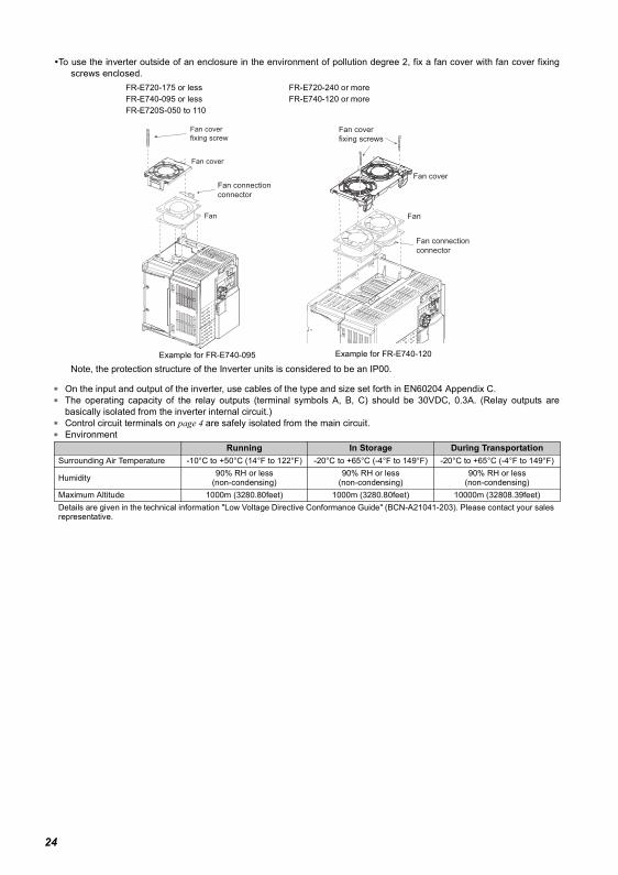
To use the inverter outside of an enclosure in the environment of pollution degree 2, fix a fan cover with fan cover fixingscrews enclosed.
Note, the protection structure of the Inverter units is considered to be an IP00.
∗ On the input and output of the inverter, use cables of the type and size set forth in EN60204 Appendix C.∗ The operating capacity of the relay outputs (terminal symbols A, B, C) should be 30VDC, 0.3A. (Relay outputs are
basically isolated from the inverter internal circuit.)∗ Control circuit terminals on page 4 are safely isolated from the main circuit.∗ Environment
FR-E720-175 or lessFR-E740-095 or lessFR-E720S-050 to 110
Example for FR-E740-095
FR-E720-240 or moreFR-E740-120 or more
Example for FR-E740-120
Running In Storage During TransportationSurrounding Air Temperature -10°C to +50°C (14°F to 122°F) -20°C to +65°C (-4°F to 149°F) -20°C to +65°C (-4°F to 149°F)
Humidity 90% RH or less(non-condensing)
90% RH or less(non-condensing)
90% RH or less(non-condensing)
Maximum Altitude 1000m (3280.80feet) 1000m (3280.80feet) 10000m (32808.39feet)Details are given in the technical information "Low Voltage Directive Conformance Guide" (BCN-A21041-203). Please contact your sales representative.
Fan connection
connector
Fan
Fan cover
Fan cover
fixing screw
Fan
Fan cover
Fan cover
fixing screws
Fan connection
connector
24
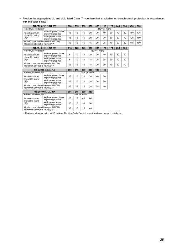
∗ Provide the appropriate UL and cUL listed Class T type fuse that is suitable for branch circuit protection in accordancewith the table below.
∗ Maximum allowable rating by US National Electrical Code.Exact size must be chosen for each installation.
FR-E720- -NA (C) 008 015 030 050 080 110 175 240 330 470 600Rated fuse voltage(V) 240V or more
Fuse Maximum allowable rating (A)∗
Without power factor improving reactor 15 15 15 20 30 40 60 70 80 150 175
With power factor improving reactor 15 15 15 20 20 30 50 60 70 125 150
Molded case circuit breaker (MCCB)Maximum allowable rating (A)* 15 15 15 15 20 25 40 60 80 110 150
FR-E740- -NA (C) 016 026 040 060 095 120 170 230 300Rated fuse voltage(V) 480V or more
Fuse Maximum allowable rating (A)∗
Without power factor improving reactor 6 10 15 20 30 40 70 80 90
With power factor improving reactor 6 10 10 15 25 35 60 70 90
Molded case circuit breaker (MCCB)Maximum allowable rating (A)* 15 15 15 15 20 30 40 50 70
FR-E720S- -NA 008 015 030 050 080 110Rated fuse voltage(V) 240V or more
Fuse Maximum allowable rating (A)∗
Without power factor improving reactor 15 20 20 30 40 60
With power factor improving reactor 15 20 20 20 30 50
Molded case circuit breaker (MCCB)Maximum allowable rating (A)* 15 15 15 20 25 40
FR-E710W- -NA 008 015 030 050Rated fuse voltage(V) 115V or more
Fuse Maximum allowable rating (A)∗
Without power factor improving reactor 20 20 40 60
With power factor improving reactor 20 20 30 50
Molded case circuit breaker (MCCB)Maximum allowable rating (A)* 15 15 25 40
25
∗ When using the electronic thermal relay function as motor overload protection, set the rated motor current to Pr. 9Electronic thermal O/L relay.
∗ Short circuit current ratings100V classSuitable For Use in A Circuit Capable of Delivering Not More Than 5 kA rms Symmetrical Amperes, 132 V Maximum.200V classSuitable For Use in A Circuit Capable of Delivering Not More Than 5 kA rms Symmetrical Amperes, 264 V Maximum.400V classSuitable For Use in A Circuit Capable of Delivering Not More Than 5 kA rms Symmetrical Amperes, 528 V Maximum.
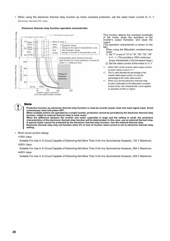
This function detects the overload (overheat)of the motor, stops the operation of theinverter's output transistor, and stops theoutput. (The operation characteristic is shown on theleft)
When using the Mitsubishi constant-torquemotor1) Set "1" or any of "13" to "16", "50", "53", "54"
in Pr. 71. (This provides a 100% continuous torque characteristic in the low-speed range.)
2) Set the rated current of the motor in Pr. 9.∗1 When 50% of the inverter rated output current
(current value) is set in Pr. 9 ∗2 The % value denotes the percentage to the
inverter rated output current. It is not the percentage to the motor rated current.
∗3 When you set the electronic thermal relay function dedicated to the Mitsubishi constant-torque motor, this characteristic curve applies to operation at 6Hz or higher.
Note⋅ Protective function by electronic thermal relay function is reset by inverter power reset and reset signal input. Avoid
unnecessary reset and power-OFF.⋅ When multiple motors are operated by a single inverter, protection cannot be provided by the electronic thermal relay
function. Install an external thermal relay to each motor.⋅ When the difference between the inverter and motor capacities is large and the setting is small, the protective
characteristics of the electronic thermal relay function will be deteriorated. In this case, use an external thermal relay.⋅ A special motor cannot be protected by the electronic thermal relay function. Use the external thermal relay.⋅ Electronic thermal relay may not function when 5% or less of inverter rated current is set to electronic thermal relay
setting.
Operation range
Range on the right of characteristic curve
Non-operation range
Range on the left of characteristic curve
Range for
transistor
protection
Inverter output current(%)(% to the rated inverter current)
52.5% 105%
50 100 150
60
120
180
240
50
60
70
(min
) unit d
ispla
y in this
range
Opera
tion tim
e (
min
)
Pr. 9 = 50% setting of inverter rating*1, 2
Pr. 9 = 100% setting of inverter rating*2
(s)
unit d
ispla
y in this
range
Opera
tion tim
e (
s)
Characteristic when electronic thermal
relay function for motor protection is turned off
(when Pr. 9 setting is 0(A))
6Hz
20Hz
10Hz
6Hz
0.5Hz
30Hz or more *330Hz or more *3
20Hz10Hz
0.5Hz
230
Electronic thermal relay function operation characteristic
26
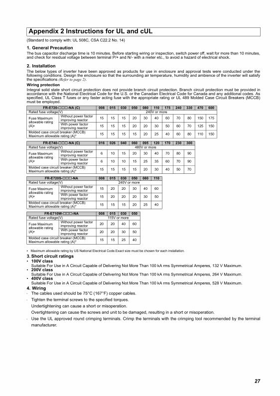
(Standard to comply with: UL 508C, CSA C22.2 No. 14)
1. General PrecautionThe bus capacitor discharge time is 10 minutes. Before starting wiring or inspection, switch power off, wait for more than 10 minutes,and check for residual voltage between terminal P/+ and N/- with a meter etc., to avoid a hazard of electrical shock.
2. InstallationThe below types of inverter have been approved as products for use in enclosure and approval tests were conducted under thefollowing conditions. Design the enclosure so that the surrounding air temperature, humidity and ambience of the inverter will satisfythe specifications (Refer to page 2).Wiring protectionIntegral solid state short circuit protection does not provide branch circuit protection. Branch circuit protection must be provided inaccordance with the National Electrical Code for the U.S. or the Canadian Electrical Code for Canada and any additional codes. Asspecified, UL Class T fuses or any faster acting fuse with the appropriate rating or UL 489 Molded Case Circuit Breakers (MCCB)must be employed.
∗ Maximum allowable rating by US National Electrical Code.Exact size must be chosen for each installation.
3. Short circuit ratings• 100V class
Suitable For Use in A Circuit Capable of Delivering Not More Than 100 kA rms Symmetrical Amperes, 132 V Maximum.• 200V class
Suitable For Use in A Circuit Capable of Delivering Not More Than 100 kA rms Symmetrical Amperes, 264 V Maximum.• 400V class
Suitable For Use in A Circuit Capable of Delivering Not More Than 100 kA rms Symmetrical Amperes, 528 V Maximum.4. Wiring⋅ The cables used should be 75°C (167°F) copper cables.⋅ Tighten the terminal screws to the specified torques.
Undertightening can cause a short or misoperation.Overtightening can cause the screws and unit to be damaged, resulting in a short or misoperation.
⋅ Use the UL approved round crimping terminals. Crimp the terminals with the crimping tool recommended by the terminalmanufacturer.
Appendix 2 Instructions for UL and cUL
FR-E720- -NA (C) 008 015 030 050 080 110 175 240 330 470 600Rated fuse voltage(V) 240V or more
Fuse Maximum allowable rating (A)∗
Without power factor improving reactor 15 15 15 20 30 40 60 70 80 150 175
With power factor improving reactor 15 15 15 20 20 30 50 60 70 125 150
Molded case circuit breaker (MCCB)Maximum allowable rating (A)* 15 15 15 15 20 25 40 60 80 110 150
FR-E740- -NA (C) 016 026 040 060 095 120 170 230 300Rated fuse voltage(V) 480V or more
Fuse Maximum allowable rating (A)∗
Without power factor improving reactor 6 10 15 20 30 40 70 80 90
With power factor improving reactor 6 10 10 15 25 35 60 70 90
Molded case circuit breaker (MCCB)Maximum allowable rating (A)* 15 15 15 15 20 30 40 50 70
FR-E720S- -NA 008 015 030 050 080 110Rated fuse voltage(V) 240V or more
Fuse Maximum allowable rating (A)∗
Without power factor improving reactor 15 20 20 30 40 60
With power factor improving reactor 15 20 20 20 30 50
Molded case circuit breaker (MCCB)Maximum allowable rating (A)* 15 15 15 20 25 40
FR-E710W- -NA 008 015 030 050Rated fuse voltage(V) 115V or more
Fuse Maximum allowable rating (A)∗
Without power factor improving reactor 20 20 40 60
With power factor improving reactor 20 20 30 50
Molded case circuit breaker (MCCB)Maximum allowable rating (A)* 15 15 25 40
27
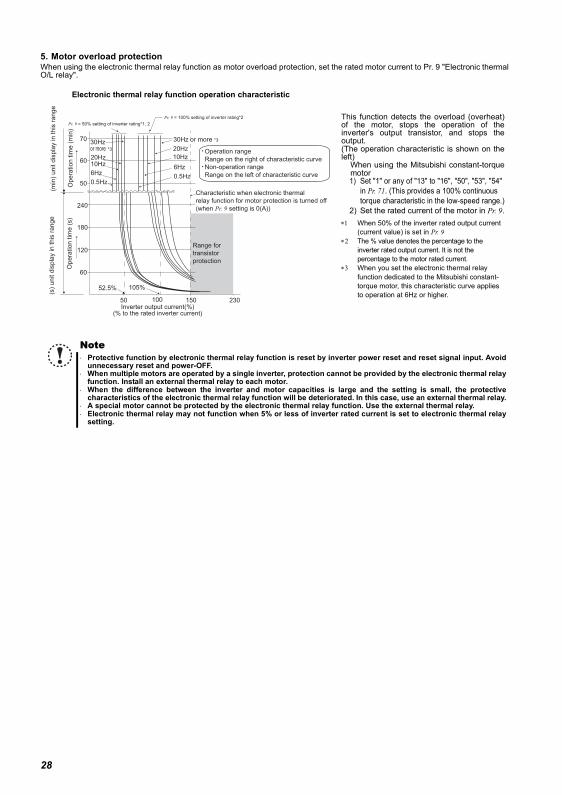
5. Motor overload protectionWhen using the electronic thermal relay function as motor overload protection, set the rated motor current to Pr. 9 "Electronic thermalO/L relay".
This function detects the overload (overheat)of the motor, stops the operation of theinverter's output transistor, and stops theoutput. (The operation characteristic is shown on theleft)
When using the Mitsubishi constant-torquemotor1) Set "1" or any of "13" to "16", "50", "53", "54"
in Pr. 71. (This provides a 100% continuous torque characteristic in the low-speed range.)
2) Set the rated current of the motor in Pr. 9.∗1 When 50% of the inverter rated output current
(current value) is set in Pr. 9 ∗2 The % value denotes the percentage to the
inverter rated output current. It is not the percentage to the motor rated current.
∗3 When you set the electronic thermal relay function dedicated to the Mitsubishi constant-torque motor, this characteristic curve applies to operation at 6Hz or higher.
Note⋅ Protective function by electronic thermal relay function is reset by inverter power reset and reset signal input. Avoid
unnecessary reset and power-OFF.⋅ When multiple motors are operated by a single inverter, protection cannot be provided by the electronic thermal relay
function. Install an external thermal relay to each motor.⋅ When the difference between the inverter and motor capacities is large and the setting is small, the protective
characteristics of the electronic thermal relay function will be deteriorated. In this case, use an external thermal relay.⋅ A special motor cannot be protected by the electronic thermal relay function. Use the external thermal relay.⋅ Electronic thermal relay may not function when 5% or less of inverter rated current is set to electronic thermal relay
setting.
Operation range
Range on the right of characteristic curve
Non-operation range
Range on the left of characteristic curve
Range for
transistor
protection
Inverter output current(%)(% to the rated inverter current)
52.5% 105%
50 100 150
60
120
180
240
50
60
70
(min
) unit d
ispla
y in this
range
Opera
tion tim
e (
min
)
Pr. 9 = 50% setting of inverter rating*1, 2
Pr. 9 = 100% setting of inverter rating*2
(s)
unit d
ispla
y in this
range
Opera
tion tim
e (
s)
Characteristic when electronic thermal
relay function for motor protection is turned off
(when Pr. 9 setting is 0(A))
6Hz
20Hz
10Hz
6Hz
0.5Hz
30Hz or more *330Hz or more *3
20Hz10Hz
0.5Hz
230
Electronic thermal relay function operation characteristic
28
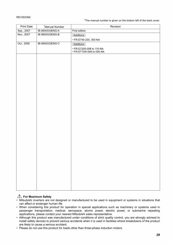
REVISIONS*The manual number is given on the bottom left of the back cover.
For Maximum Safety• Mitsubishi inverters are not designed or manufactured to be used in equipment or systems in situations that
can affect or endanger human life.• When considering this product for operation in special applications such as machinery or systems used in
passenger transportation, medical, aerospace, atomic power, electric power, or submarine repeatingapplications, please contact your nearest Mitsubishi sales representative.
• Although this product was manufactured under conditions of strict quality control, you are strongly advised toinstall safety devices to prevent serious accidents when it is used in facilities where breakdowns of the productare likely to cause a serious accident.
• Please do not use this product for loads other than three-phase induction motors.
Print Date *Manual Number RevisionSep., 2007 IB-0600333ENG-A First editionNov., 2007 IB-0600333ENG-B
• FR-E740-230, 300-NAOct., 2008 IB-0600333ENG-C
• FR-E720S-008 to 110-NA• FR-E710W-008 to 050-NA
Additions
Additions
29


![CTK2000 CTK3000 f - support.casio.comsupport.casio.com/storage/fr/manual/pdf/FR/008/CTK... · Guide général F-4 Utilisez les touches numériques et les touches [–] et [+] pour](https://img.pdfslide.net/doc/110x75/5ae100807f8b9a1c248dd7a4/ctk2000-ctk3000-f-gnral-f-4-utilisez-les-touches-numriques-et-les-touches-.jpg)