Embed Size (px)
Citation preview

Abstract— Novel heat treatments for aerospace aluminium
alloys allow simultaneous improvements of ductility and
strength. In the present study we consider the effects of retro-
ageing and interrupted heat treatments of aluminium alloy
AA7050 on its fatigue behaviour, including the consequences
of crack closure for fatigue crack growth rate. SEM
fractography is used to visualise striations associated with
crack front advance in individual cycles, and a correlation is
made with the overall crack growth rate, and the conditions of
crack propagation.
Index Terms — Aluminium alloy, ageing treatment,
fractography, fatigue crack
I. INTRODUCTION
eductions in weight have always been a major criterion
for the selection of materials for aerospace
applications. This led to the development of various high
strength aluminum alloys during the last half a century [1].
The key role of the 7050-T7451 aluminum alloy plate have
been extensively used for manufacturing of aircraft
structural components due to their high strength, low
density, excellent hot workability, fracture toughness and
fatigue resistance [2]. Moreover, the overageing heat
treatment T7451 has been traditionally applied to reduce
the susceptibility of commercial Al-7075-T651 alloy to
stress corrosion cracking (SCC). However, this heat
treatment necessarily leads to a sacrifice of the maximum
strength of this alloy [3]. Accordingly, multiple-stage
ageing treatments have been developed for aluminum alloys
to further enhance the mechanical property response, [4]. In
Manuscript received January 05, 2016; revised January 10, 2016. This
work was supported in part by the CAPES under Grant BEX 2606/15-1 and
BEX 2638/15-0. AMK acknowledges funding received for the MBLEM
laboratory at Oxford through EU FP7 project iSTRESS (604646).
A. L. M. Carvalho is with Department of Material Engineering, State
University of Ponta Grossa, PR, Brazil, 84030-900 ([email protected]).
J. P. Martins is with Department of Chemical Engineering, Federal
University of Technology–Paraná, 84016-210 ([email protected]).
E. Salvati is with Department of Engineering Science, University of
Oxford, U.K, OX1 3PJ ([email protected]).
T. Sui is with Department of Engineering Science, University of Oxford,
U.K, OX1 3PJ ([email protected]).
A. M. Korsunsky is Head of MBLEM (Multi-Beam Laboratory for
Engineering Microscopy), Department of Engineering Science, University of
Oxford, U.K, OX1 3PJ ([email protected]). * Corresponding author
order to improve the compromise between mechanical
strength and corrosion resistance, it has been proposed to
replace the traditional two-step heat treatment of these
alloys by a three-step heat treatment, called retrogression
and re-ageing (RRA) treatment [5].
Recent experimental studies have reported new heat
treatment schedules (designated T6I4, I=interrupted) that,
when applied to Al alloys, offer the possibility of avoiding
the inverse correlations between some of the important
mechanical properties, such as yield strength and
elongation, and yield strength and fracture toughness [6].
Among the aging technologies, interrupted multi-step
aging attracts much attention, which may lead to
simultaneous increase in both tensile and fracture
toughness of a wide range of aging- hardening aluminum
alloys [7]
These observations have received much attention from
both industry (who are interested in creating new property
profiles for existing alloys) and academia (because of
modifying the size, morphology and distribution of particles
in aged aluminum alloys are not deeply understood);
However, few studies have referred to T6I4 and RRA-
treated 7050 alloy in order to explore the potential of
multistage ageing treatments on the fatigue nucleation and
crack growth behavior.
The purpose of this study is investigate in details the
influence of T6I4-65 and RRA ageing treatments to
produce different combinations of tensile properties on the
fatigue crack growth rate and fracture behaviors. It was
applied single overload to evaluation its influence at the
retardation fatigue crack growth rate and fracture process.
II. EXPERIMENTAL PROCEDURE
A. Material
The material used in the present study was a 7050-T7451
aluminium alloy plate of 3” (76.8mm) thickness and the
composition (in wt%) of “5.58Zn, 1.88Mg, 2.00Cu, 0.07Fe,
0.02Si, 0.15Zr, Al balance”, provided by the Embraer
Company. All specimens were removed from the
longitudinal (LD) to rolling direction. Tensile properties of
the material in the T7451, T6I4-65 and RRA conditions
such as: the ultimate tensile strength (UTS), the yield
strength and the reduction in area, respectively, are shown
in Table I. It is worth noting that the RRA condition gives
André L. M. Carvalho, Juliana P. Martins, Enrico Salvati, Tan Sui, Alexander M. Korsunsky*
Fractography of Fatigue Cracks in Aluminium
Alloy AA7050 Subjected to Interrupted Ageing
and Retro-Ageing Heat Treatments
R
Proceedings of the International MultiConference of Engineers and Computer Scientists 2016 Vol II, IMECS 2016, March 16 - 18, 2016, Hong Kong
ISBN: 978-988-14047-6-3 ISSN: 2078-0958 (Print); ISSN: 2078-0966 (Online)
IMECS 2016

tensile properties superior to the T7451 condition, whereas
the T6I4-65 condition has a decrease of “19.46%” in the
yield strength compared to the as-received T7451 condition.
Table I. Tensile properties results from the T7451, T6I4-65 and RRA
conditions.
Condition YS (MPa) UTS(MPa) R.A. (%)
T7451 492 ± 10.5 592 ± 23 3.7 ± 1.2
T6I4-65 452 ± 10.3 534 ± 14.5 38.17 ± 2.9
RRA 540 ± 15.5 613.20 ± 4.8 22.79± 3.2
B. Heat Treatment
Two types of heat treatment were considered in the
present study, carried out according to the following
schedules. The first, denoted the T6I4-65 condition, was
solution treated at “485 °C for 4 h”, water quenched,
ageing was interrupted at “130 °C for 15 min”, followed by
ageing at “65ºC for two months”. The second, denoted the
RRA condition, was solution treated at “485 °C for 4 h”,
water quenched, and aged at “130°C for 24h” followed by
retrogression at “185°C for 20 min”, followed by ageing at
“65ºC for two months”. The other condition considered for
reference was the as-received T7451 condition.
C. Fatigue Fracture Surface Analysis
Fractography analysis of fatigue crack surfaces was
carried out at the locations of crack growth in the near-
threshold, low and high ΔK regimes, as also at the rupture
regime, for the T7451, T6I4-65, and RRA conditions. All
fracture analysis has been performed at the Tescan
FIB/SEM LIRA3XM using secondary electron mode.
Fatigue crack propagation testing was performed under
constant stress amplitude using a servohydraulic “15 kN”
fatigue machine on compact tension (CT) specimens (Fig
1), with plate width “W=50 mm” and thickness “9.5 mm”
machined from the plate with L-T orientation, with the
crack growth aligned with the transverse direction. All
samples were pre-cracked as described in ASTM E 647 -05
[8]. The frequency of “10 Hz” and stress ratio of “R = 0.1”
were used for testing. Crack length was measured from the
digital camera attached to Questar long range telescope. A
single overload (OL) of 50% was applied to evaluate its
influence on the retardation of fatigue crack growth rate
and the subsequent crack propagation process.
Fig 1. Geometry of the C(T) specimen (dimensions in mm).
III. RESULTS AND DISCUSSION
A. Fracture Surface Analysis
Examination of the surfaces reveals a fractured surface
region close to perpendicular to the principal applied load,
accompanied by shear fracture at specimen edges. In the
three conditions tested, double shear lips were evident
along the fracture path. The crack extension mechanism
depends on the crack driving force that varies between pure
Mode I in the main crack, and a mixture of Mode I and
Mode II at the shear lips, and at locations of uneven
fracture surface within the main crack [9]. The surface
roughness was evaluated using a Alicona optical Infinite
Focus 3D micro-coordinate measurement equipment for the
three conditions in terms of the surface roughness
parameter RS according to the ASM Handbook [10]. RS is
the ratio RS = St/A given from the true surface area St
divided by the projected area A. As shown in Fig 2, the
T7451 condition reveals higher RS values measured along
at chosen segments corresponding to similar crack growth
position for the three conditions investigated. The average
values measured were 1.23 for T7451, 1.15 for, T6I4-65,
and 1.19 for RRA, respectively (Fig 2).
0 2 4 6 8 10 12 14
0.96
1.08
1.20
1.32
1.44
Su
rfac
e ro
ug
hn
ess
par
amet
er (
Rs)
Condition
T7451
T6I4-65
RRA
Fracture surface segment
Fig 2. Surface roughness parameter from the three conditions.
In the experimental results reported in [11] on the
aluminium alloy showed increase crack growth resistance
of the plate was attributed two factors: i) a lower ductility
in relation to other higher ductility and ii) a pronounced
crack closure at crack path promoted by higher surface
roughness. In the present study, the T7451 condition
showed higher surface roughness (Fig 2), but also lower
ductility compared other two conditions. This suggests
the significance of roughness-induced crack closure
amongst different crack retardation mechanisms for this
condition.
B. Near-threshold regime
Fig 3 a-c shows the SEM fractographs of the fatigue
crack growth specimens tested at the near-threshold regime.
It can be seen that crack growth occurs on multiple facets at
different angles with respect to each other for all three
conditions studied. The propensity for the formation of
facets is more evident in the RRA condition in which the
features also appear larger than in the T6I4-65 and T7451
conditions. In Fig 3c, changes in the orientation of facets
Proceedings of the International MultiConference of Engineers and Computer Scientists 2016 Vol II, IMECS 2016, March 16 - 18, 2016, Hong Kong
ISBN: 978-988-14047-6-3 ISSN: 2078-0958 (Print); ISSN: 2078-0966 (Online)
IMECS 2016

can be noted (indicated by black arrows), likely to be
associated with the crack path crossing a grain boundary.
Fig 3. SEM fractographs in the near-threshold regime of the alloy in the
three conditions (a) T7451 and (b) T6I4-65 and (c) RRA (crack propagation
direction is from left to right).
C. Low ΔK regime
The results of the examination of the fracture surfaces
conducted in the low ΔK regime can be seen in Fig 4 a-c.
For the T7451 condition (Fig 4a), the formation of deep
pockets is noticeable, as also is the absence of facets.
Fig 4. SEM fractographs in the Paris growth regime (Low ΔK level) of the
alloy in three conditions (a) T7451, (b) T6I4-65 and (c) RRA (crack
propagation direction is from left to right).
a)
c)
b)
c)
a)
b)
Proceedings of the International MultiConference of Engineers and Computer Scientists 2016 Vol II, IMECS 2016, March 16 - 18, 2016, Hong Kong
ISBN: 978-988-14047-6-3 ISSN: 2078-0958 (Print); ISSN: 2078-0966 (Online)
IMECS 2016
In contrast, the T6I4-65 and RRA conditions (Fig 4b-c)
has shown some different features present at the fracture
surface, such as shallow pockets, a predominance of small
flat facets (indicated by the black arrows), and the small
and large facets containing multiple wavy regions encircled
using dashed lines. Moreover, for all three conditions it is
possible to notice the presence secondary cracks. Void
formation at the coarse grain boundary is also observed,
except for the RRA condition.
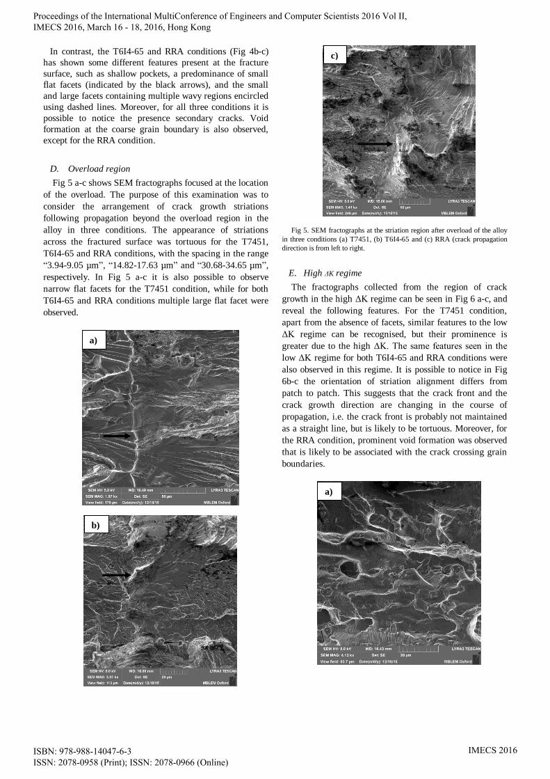
D. Overload region
Fig 5 a-c shows SEM fractographs focused at the location
of the overload. The purpose of this examination was to
consider the arrangement of crack growth striations
following propagation beyond the overload region in the
alloy in three conditions. The appearance of striations
across the fractured surface was tortuous for the T7451,
T6I4-65 and RRA conditions, with the spacing in the range
“3.94-9.05 µm”, “14.82-17.63 µm” and “30.68-34.65 µm”,
respectively. In Fig 5 a-c it is also possible to observe
narrow flat facets for the T7451 condition, while for both
T6I4-65 and RRA conditions multiple large flat facet were
observed.
Fig 5. SEM fractographs at the striation region after overload of the alloy
in three conditions (a) T7451, (b) T6I4-65 and (c) RRA (crack propagation
direction is from left to right.
E. High ΔK regime
The fractographs collected from the region of crack
growth in the high ΔK regime can be seen in Fig 6 a-c, and
reveal the following features. For the T7451 condition,
apart from the absence of facets, similar features to the low
ΔK regime can be recognised, but their prominence is
greater due to the high ΔK. The same features seen in the
low ΔK regime for both T6I4-65 and RRA conditions were
also observed in this regime. It is possible to notice in Fig
6b-c the orientation of striation alignment differs from
patch to patch. This suggests that the crack front and the
crack growth direction are changing in the course of
propagation, i.e. the crack front is probably not maintained
as a straight line, but is likely to be tortuous. Moreover, for
the RRA condition, prominent void formation was observed
that is likely to be associated with the crack crossing grain
boundaries.
a)
b)
c)
a)
Proceedings of the International MultiConference of Engineers and Computer Scientists 2016 Vol II, IMECS 2016, March 16 - 18, 2016, Hong Kong
ISBN: 978-988-14047-6-3 ISSN: 2078-0958 (Print); ISSN: 2078-0966 (Online)
IMECS 2016

Fig 6 SEM fractographs in the Paris growth regime (high ΔK) of the alloy
in three conditions show; (a) for the T7451 the absence of facets, for both (b)
T6I4-65 and (c) RRA different striation alignment orientation (crack
propagation direction is from left to right).
F. Rupture regime
In the fatigue rupture region, for the T7451, T6I4-65 and
RRA conditions, fractographic features can be seen in Fig
7(a-c). Predominantly ductile fracture surfaces were
observed, characterised by the large dimples of the order of
“2.5–9.5µm”, “2.2-17.4 µm” and “2.0-12.0 µm” in
diameter, respectively. Aggregates of secondary particles
could often be seen within these dimples. For the three
conditions, intergranular failure along grain boundaries in
the fracture surface can be found, with the failure mode
being predominantly transgranular. For all regimes
investigated for the three conditions, meandering crack
surface morphology was always observed.
From the results reported in the literature it is well
known that the spacing between adjacent striations
correlates with the average crack growth rate per cycle for
cyclic loads [3]. Consequently, the data displayed in Table
II for the measured striation spacing at the fractured surface
for the three conditions suggests a correlation with fatigue
crack growth rate, as shown in Table III.
Fig 7. SEM fractographs in rupture regime of the alloy in three conditions
(a)T7451, T6I4-65 (b) and (c) RRA (crack propagation direction is from left
to right)
a)
c)
b)
b)
c)
Proceedings of the International MultiConference of Engineers and Computer Scientists 2016 Vol II, IMECS 2016, March 16 - 18, 2016, Hong Kong
ISBN: 978-988-14047-6-3 ISSN: 2078-0958 (Print); ISSN: 2078-0966 (Online)
IMECS 2016

From Table II it is possible to note the narrow fatigue
striation distance for both RRA and T6I4-65 conditions in
low ΔK regime, indicating slow fatigue crack growth rate,
i.e. a higher resistance to fatigue crack growth compared to
the traditional T7451 condition.
Table II. Experimental results of the measured striation spacing from
fractured surface at the different regimes of the three conditions investigated.
This behaviour is maintained until in the moderate ΔK
regime (corresponding ΔK=15 in Tab.3). It is coincident
with the experimental result shown in Table III for the
three conditions.
Table III. Fatigue crack growth data of 7050 alloy for the three conditions.
IV. CONCLUSION
The present study investigated the influence of two types
of novel multi-stage heat treatments (T6I4-65 and RRA) on
the fractographic appearance of fatigue crack surfaces. The
observations were contrasted and compared with the
traditional T7451 condition. Fracture analysis was carried
out for the near-threshold, low and high ΔK regimes, as
well as following the application of a single 50% overload,
and for the rupture regime.
The occurrence of uneven areas at the fatigue fracture
surface corresponds to crack meandering that increases the
total fracture surface and enhances the material resistance
to crack propagation. It is surmised that the appearance of
crack deflection features is associated with the location of
elongated grain boundaries aligned in the longitudinal
(rolling) direction of the AA 7050 aluminium alloy. This
highlights the importance of mechanical processing and
heat treatment conditions for the control of microstructure
and mechanical properties of aluminium alloys subjected to
complex procedures for the enhancement of performance in
aerospace applications.
ACKNOWLEDGMENT
AMK acknowledges access to the facilities at the
Research Complex at Harwell (RCaH) granted to the Centre
for In situ Processing Studies (CIPS).
REFERENCES
[1] M. N. Desmukha, R.K. Pandey, A.K. Mukhopadhyay, “Effect of
ageing treatments on the kinetics of fatigue crack growth in 7010
aluminium alloy,” Materials Science and Engineering A, vol. 435–
436, pp. 318–326, 2006.
[2] D. Feng, X.M Zhang, S.D.Liu, T.Wang, Z.Z.Wu, Y.W.Guo, “The
effect of pre-ageing temperature and retrogression heating rate on the
microstructure and properties of AA7055,” Materials Science &
Engineering A, vol. 588, pp. 34–42, Dec. 2013.
[3] Y. L. Wang, Q. L. Pan, L. L. Wei, B. Li, Y. Wang, “Effect of
retrogression and reaging treatment on the microstructure and fatigue
crack growth behavior of 7050 aluminium alloy thick plate,”
Materials and Design, vol. 55, pp. 857–863, Mar. 2014.
[4] D.D. Risantia, M. Yinb, P.E.J.R.D. del Castillo, S. van der Zwaagc,
“A systematic study of the effect of interrupted ageing conditions on
the strength and toughness development of AA6061,” Materials
Science and Engineering A, vol. 523, no 1-2, pp. 99–111, Oct. 2009.
[5] T. Marlaud, A. Deschamps, F. Bley, W. Lefebvre, B. Baroux,
“Evolution of precipitate microstructures during the retrogression
and re-ageing heat treatment of an Al–Zn–Mg–Cu alloy,” Acta
Materialia vol. 58, no 14, pp. 4814–4826, Aug. 2010.
[6] M.E. Burba, M.J. Caton, S.K. JHA, and C.J. Szczepanski, “Effect of
Aging Treatment on Fatigue Behavior of an Al-Cu-Mg-Ag Alloy,”
The Minerals, Metals & Materials Society and ASM International,
vol. 44A, no 11, pp. 4954-4967, Nov. 2013.
[7] Z. Baohong, X. Baiqing, Z. Yong, Z. Jianbo, W. Feng, and L.
Zhihui, “Microstructure and properties characteristic during
interrupted multi-step aging in Al-Cu-Mg-Ag-Zr alloy,” RARE
METALS, vol. 30, no. 4, pp. 419-423, Aug. 2011.
[8] ASTM Test Methods for Measurement of Fatigue Crack Growth
Rates, ASTM Standard, E 647-95a, 2005.
[9] P. F. P. de Matos “Plasticity induced fatigue crack closure:
Modelling and Experiments,” Ph.D. thesis, Dept. Eng. Sci., Oxford
Univ., Oxford, UK, 2008.
[10] Fractography, vol. 12, ASM International: the materials information
society, USA, 1998. pp. 374–378.
[11] A.T. Kermanidis and Sp.G. Pantelakis, “Prediction of crack growth
following a single overload in aluminum alloy with sheet and plate
microstructure,” Engineering Fracture Mechanics vol. 78, no 11, pp.
2325–2337, July 2011.
condition C
(x10-10)
n da/dN=C(ΔK)n (m/cycle) (x 10-7)
8* 10* 15* 20*
T7451 1.688 2.96 0.80 1.54 5.11 11.98
T6I4-65 0.028 4.46 0.30 0.81 4.93 17.77
RRA 0.003 5.14 0.13 0.41 3.33 14.60
*ΔK=MPa (m)0.5
Condition Average striation spacing (µm)
Low ΔK After OL Moderate ΔK High ΔK
T7451 0.191 0.128 0.220 0.595
T6I4-65 0.121 0.104 0.151 0.490
RRA 0.097 0.130 0.165 0.485
Proceedings of the International MultiConference of Engineers and Computer Scientists 2016 Vol II, IMECS 2016, March 16 - 18, 2016, Hong Kong
ISBN: 978-988-14047-6-3 ISSN: 2078-0958 (Print); ISSN: 2078-0966 (Online)
IMECS 2016