Embed Size (px)
Citation preview

Tallennusnimi: Weather mast 7 and 10 m
Frangible Safety Weather Masts
INSTALLATION MANUAL AllWeather Inc.
10 m lattice mast Revision B

WEATHER MASTS, HINGED BASE FRAME Revision 1.2 Page 1 (28) INSTALLATION MANUAL 2.3.2005 WeatherMastAWIRev1-2.doc
CONTENTS
1 GENERAL...................................................................................................................2 1.1 Symbols used in this manual ................................................................................2 1.2 Requirements of ICAO ........................................................................................3 1.3 Mast family of Exel Oyj .......................................................................................3 1.4 Exel lattice masts ................................................................................................4
2 Foundation.................................................................................................................6 2.1 Foundation design..............................................................................................6 2.2 Preparation of foundation....................................................................................8
2.2.1 Equipment needed for preparation of foundation ......................................9 2.2.2 Work instruction for casting of foundation ................................................9
3 LATTICE MAST ASSEMBLY..........................................................................................11 3.1 Unpacking and handling of mast .......................................................................11 3.2 Joining of mast modules....................................................................................11
3.2.1 Equipment needed for joining mast modules ..........................................11 3.2.2 Tightening torque in joining mast modules .............................................12 3.2.3 Work instruction for joining mast modules..............................................13
3.3 Mounting of base frame to the mast ...................................................................15 3.3.1 Accessories needed for mounting the base frame....................................16 3.3.2 Tightening torque for base frame screws ................................................16 3.3.3 Work instruction for mounting the base frame.........................................17
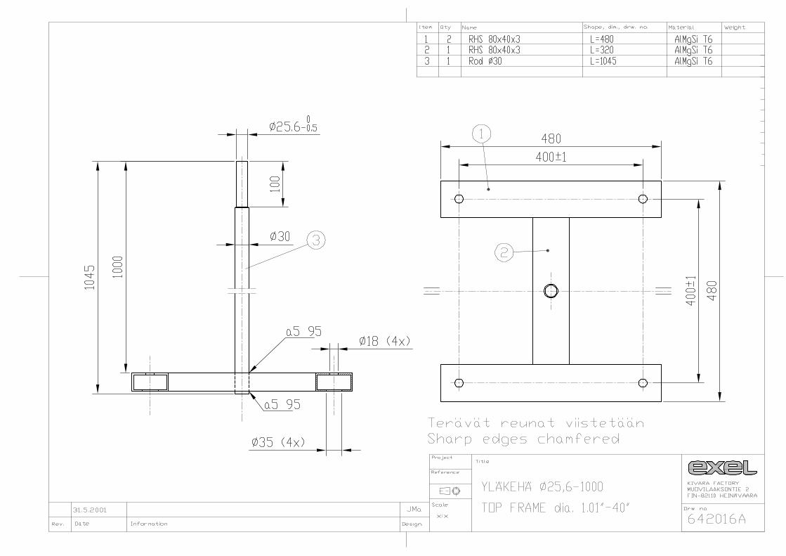
3.4 Installations of the top section of the mast ...........................................................18 3.4.1 Top frame ..........................................................................................18
3.5 Installation of electrical wires .............................................................................18 3.5.1 Equipment needed for installation of electrical wire cover tubes ................18 3.5.2 Work instruction for wiring....................................................................18
4 MOUNTING AND ERECTING THE MAST....................................................................19 4.1 Tools needed for mounting the mast...................................................................19 4.2 Tightening torque applied in mounting the mast...................................................19 4.3 Moving the lattice mast to its’ final position .........................................................19 4.4 Preparation of foundation for erection of the mast................................................20
4.4.1 Work instruction for erection of a mast...................................................20
5 USE AND MAINTENANCE OF LATTICE MASTS............................................................23 5.1 Lowering and raising of lattice mast....................................................................23
5.1.1 Tools needed for lowering and raising the mast, tightening torque ............23 5.1.2 Work instruction for lowering and raising of lattice mast...........................23
5.2 Repair painting ................................................................................................25 5.2.1 Material needed for repair painting .......................................................25 5.2.2 Repair painting ...................................................................................25
5.3 Glass fibre tube repair ......................................................................................26 5.3.1 Material needed for glass fibre tube repair .............................................26 5.3.2 Repairing the damage .........................................................................26
6 LISTS OF ILLUSTRATIONS AND TABLES.......................................................................28 6.1 List of illustrations .............................................................................................28 6.2 List of tables.....................................................................................................28
APPENDICES

WEATHER MASTS, HINGED BASE FRAME Revision 1.2 Page 2 (28) INSTALLATION MANUAL 2.3.2005 WeatherMastAWIRev1-2.doc
1 GENERAL
1.1 Symbols used in this manual
Specific symbols are used in this manual in order to attract readers’ attention to information of special importance. These symbols, their reference and explanations are presented in the table below. Symbol Referent Explanation
INFO • A useful hint to facilitate installation.
NOTE • In case of incorrect action, the structures are in danger of being broken. When performing this action, please exercise extreme caution.
• Note related to the matter.
DANGER • In case of incorrect action, fitters or persons in the proximity are in danger of accident. Please exercise extreme caution when performing this action.
REFERENCE • Further information about the subject elsewhere in the manual
Table 1: Symbols.

WEATHER MASTS, HINGED BASE FRAME Revision 1.2 Page 3 (28) INSTALLATION MANUAL 2.3.2005 WeatherMastAWIRev1-2.doc
1.2 Requirements of ICAO
According to the requirements of ICAO (International Civil Aviation Organisation) all airports operating under rules of ICAO shall be equipped with frangible safety approach light masts from the beginning of the year 2005 onwards. Below is an extract from International Standards and Recommended practices, Annex 14 Vol.1, second edition July 1995, § 5.3.13. “Elevated approach lights 5.3.1.3 Elevated approach lights and their supporting structures shall
be frangible except that, in portion of the approach lighting system beyond 300 m from the threshold:
a) where the height of the supporting structure exceeds 12 m, the
frangibility requirements shall apply to the top of 12 m only; and
b) where a supporting structure is surrounded by non-frangible
objects, only that part of the structure that extends above the surrounding objects shall be frangible.
5.3.1.4 The provisions of 5.3.13 shall not require the replacement of
existing installations before 1 January 2005. 5.3.1.5 When an approach light fixture or supporting structure is not
in itself sufficiently conspicuous, it shall be suitably marked.” (Annex 14. AERODROMES, International Standards and
Recommended Practices, Montreal: International Civil Aviation Organisation, July 1995 Volume 1, Second Edition.)
Wind direction indicators and anemometers follow the same ruling. Attachment C to ICAO State Letter AN 4/1.1.37-91/64, Interim Guidance on Frangibility, item 1.2, “Obstacles to be made frangible” lists, among other things, wind direction indicators, anemometers and transmissometers. Draft Aerodrome Design Manual 6, chapter 5 (from 1999) lists navigational aids that shall be verified for frangibility through full scale dynamic testing. “Such aids include approach lighting towers, wind direction indicators, transmissiometers,…”.
1.3 Mast family of Exel Oyj
Exel Oyj has accepted the challenge of ICAO requirements by designing a light, frangible, approach light mast family based on composite materials. The Exel mast has passed a full-scale impact test as a proof of meeting the requirements of ICAO. In Exel masts, frangibility is a unique built-in feature and no break-away points at regular intervals used by other manufacturers are needed. If case of a collision, the mast will break down at the point of impact, and there is no danger of the broken pieces of the mast wrapping around the wing of the aircraft.

WEATHER MASTS, HINGED BASE FRAME Revision 1.2 Page 4 (28) INSTALLATION MANUAL 2.3.2005 WeatherMastAWIRev1-2.doc
Due to its design and materials, an Exel mast is light but at the same time very stiff and strong, and can thus well withstand wind loads and jet blast loads caused by aircraft jet engines. In case of a side impact, however, the mast will break down safely to small pieces. Exel masts are in practice maintenance-free and the composite materials used in them resist fatigue and corrosion. The masts will maintain their physical properties regardless of the weather and temperature. They can be safely used in maritime or other climate conditions causing corrosion. Exel-masts have been painted with visible aviation yellow colour, and therefor they do not need to be marked separately for visibility. The chosen materials make the masts transparent to electromagnetic signals. Exel masts do not distort ILS signals and as a result, the need for calibration of ILS antenna system is decreased. The shape and dimensions of Exel masts will not be deformed when the masts are lowered down for light maintenance, and consequently, re-aligning of lights is not necessary.
1.4 Exel lattice masts
Exel lattice masts have a modular construction. Medium-tall masts consist of a single module of 400 mm, and the top frame for fixing the weather instruments is mounted on top of the 400 mm module. The maximum height of single-module masts is approximately 6,5 m. In tall masts, the lower section consists of a module of 500 mm, and the top section of a module of 400 mm. The top frame is mounted on top of the 400 mm module. The maximum height of two-module masts is approximately 10 m.

WEATHER MASTS, HINGED BASE FRAME Revision 1.2 Page 5 (28) INSTALLATION MANUAL 2.3.2005 WeatherMastAWIRev1-2.doc
Illustration 1: Exel lattice mast
• The design of lattice masts has been explained more in detail in the assembly drawings and in the mast list.
WEATHER MASTS, HINGED BASE FRAME Revision 1.2 Page 6 (28) INSTALLATION MANUAL 2.3.2005 WeatherMastAWIRev1-2.doc
2 FOUNDATION
2.1 Foundation design
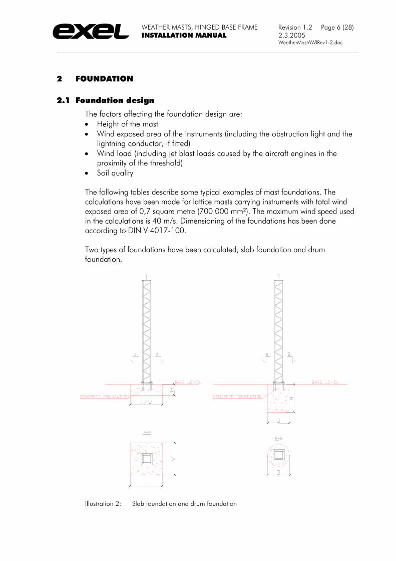
The factors affecting the foundation design are: • Height of the mast • Wind exposed area of the instruments (including the obstruction light and the
lightning conductor, if fitted) • Wind load (including jet blast loads caused by the aircraft engines in the
proximity of the threshold) • Soil quality The following tables describe some typical examples of mast foundations. The calculations have been made for lattice masts carrying instruments with total wind exposed area of 0,7 square metre (700 000 mm²). The maximum wind speed used in the calculations is 40 m/s. Dimensioning of the foundations has been done according to DIN V 4017-100. Two types of foundations have been calculated, slab foundation and drum foundation.
Illustration 2: Slab foundation and drum foundation

WEATHER MASTS, HINGED BASE FRAME Revision 1.2 Page 7 (28) INSTALLATION MANUAL 2.3.2005 WeatherMastAWIRev1-2.doc
Slab foundation
SOIL TYPE 1 SOIL TYPE 2 SOIL TYPE 3
Mast height
Type L=W H Mass L=W H Mass L H Mass
Meters - mm mm kg mm mm kg mm mm kg H = 4 Lattice 1200 400 1400 1100 400 1200 1300 500 2100 H = 7 Lattice 1400 600 2900 1300 600 2500 1600 700 4400 H = 10 Lattice 1700 700 5000 1600 700 4400 1900 800 7100
Table 2: Dimensioning of the concrete slab foundation for mast heights up to 10 m.
Drum foundation
SOIL TYPE 1 SOIL TYPE 2 SOIL TYPE 3
Mast height
Type D H Mass D H Mass
D H Mass
Meters - mm mm kg mm mm kg mm mm kg H = 4 Lattice 1200 1100 3000 1200 900 2500 H = 7 Lattice 1200 1500 4150 1200 1200 3350 H = 10 Lattice 1200 1900 5260 1200 1500 4200
Table 3: Dimensioning of the concrete drum foundation for mast heights up to 10 m. Soil type 1: Sand, sandy soil
angle of friction δ = 25° weight by volume γ = 17 kN/m³ cohesion c = 0 kN/m²
Soil type 2: Compacted coarse sand and moraine angle of friction δ = 40° weight by volume γ = 21 kN/m³ cohesion c = 0 kN/m²
Soil type 3: Hard clay (drum foundation should not be used!) angle of friction δ = 0° weight by volume γ = 19 kN/m³ cohesion c = 20 kN/m²
Concrete: > K30

WEATHER MASTS, HINGED BASE FRAME Revision 1.2 Page 8 (28) INSTALLATION MANUAL 2.3.2005 WeatherMastAWIRev1-2.doc
• In a groundwater area the foundation shall be deeper. • In a soil frost area, the foundation shall reach below the soil frost penetration
depth.
• All design values mentioned in this instruction are purely indicative. Exel Oyj shall not take responsibility for their applicability to the area in question.
• It is highly recommended to always consult a local civil engineer about the dimensioning of the foundation.
• Exel Oyj will provide the necessary load calculations (shear force and bending moment), when requested.
2.2 Preparation of foundation
Hinged base plate Part of foundation bolt remaining visible 100 ±2mm Allowed deviation of the position of the jig/base frame from the horizontal level.
± 0,3° =5,2mm/1000mm
Correct position of the base frame Even side up Table 4: Essential information necessary for preparation of foundation.
• Hot dip galvanised foundation bolts shall in no case be welded to the steel reinforcement of the foundation. Fasten the foundation bolts with wire.
• Protect the thread of the foundation bolts during the casting for example with tape.
• Plywood jigs (option) are available for locating of the foundation bolts in the concrete when casting the foundation.
• The position of foundation bolts is the same for both 400 mm and 500 mm module masts.
• The same hinged base plate can be used for both 400 mm and 500 mm masts. • See appendices: “Assembly drawings”. • See appendices: “Foundation parts”.

WEATHER MASTS, HINGED BASE FRAME Revision 1.2 Page 9 (28) INSTALLATION MANUAL 2.3.2005 WeatherMastAWIRev1-2.doc
2.2.1 Equipment needed for preparation of foundation
Measure Instrument Size - Foundation bolt, 4 pcs
641861 M24-430(1160)
Fastening of foundation bolts to the jig
Nut, 8 pcs M 24
-:- Washers, 8 pcs Ø26 -:- Wrench S=36mm Positioning of foundation bolts (alternative 1)
Casting jig 641794C 1 pc For 400 or 500 mm mast
Positioning of foundation bolts (alternative 2)
1 Base frame + locating bushes 641878, 4 pcs
For 400 or 500 mm mast
Protection of screw thread Masking tape - Fastening of screws to steel reinforcement
Wire -
Casting of foundation Normal casting accessories (moulds and steel re-inf.)
-
Verification of level of the jig Water level - Table 5: Equipment needed for preparation of foundation.
2.2.2 Work instruction for casting of foundation
If a locating jig is not available (option), the base frame can be used as a jig. Fit the base frame with locating bushes. They will centre the foundation bolts to the holes in the base frame and make sure that the bolts will be positioned accurately at their correct places in the concrete (see the illustration on the following page). • Make a cast mould with its steel reinforcements in accordance with the design
of a local civil engineer. • Place the cable duct tubes in foundation prior to casting. Recommended duct
tube IR 65.The cable duct is drawn under the ground through the foundation up to and as close as possible to either inside corner of the base plate that is facing the felling direction of the mast.
• Fasten the foundation bolts to the cast jig (or with the locating bushes to the base frame). If you use the base frame as a jig, make sure that you fasten and install the bolts correctly in accordance with the illustration on the following page, the flat surface up.
• Protect the threads in the anchor bolts by using for example tape. • Place the casting jig (or the base frame) with its bolts at its’ position. Fasten
the bolts to the steel reinforcement with wire if necessary. The foundation bolts shall remain for the length of 100 mm above the concrete surface.
• Cast concrete in the foundation mould. • Make sure that the cast jig (or base frame) is in a horizontal position. Correct
the position before the concrete hardens. • When the concrete is hard, remove the cast jig (or base frame).

WEATHER MASTS, HINGED BASE FRAME Revision 1.2 Page 10 (28) INSTALLATION MANUAL 2.3.2005 WeatherMastAWIRev1-2.doc
Illustration 3: Principal draft of foundation, casting jig and foundation bolts of the mast.

WEATHER MASTS, HINGED BASE FRAME Revision 1.2 Page 11 (28) INSTALLATION MANUAL 2.3.2005 WeatherMastAWIRev1-2.doc
3 LATTICE MAST ASSEMBLY
3.1 Unpacking and handling of mast
Unpack the mast carefully on the assembly site. Handle mast modules with care. Be sure not to damage the glass fibre structures, because they are designed to be frangible. Masts are delivered as assembled modules, which will then be connected on the assembly site. The 400 mm mast module is packed inside the 500 mm module. A joint element is mounted on top of the 500 mm module. This joint element is used for connecting modules of different sizes. On top of the 400 mm module is the top frame, to which the meteorological instruments will be attached. All necessary screws, nuts, washers and shims have been fitted.
• If any damage is found in the masts, contact the representative of Exel Oyj. Exel will either repair the damaged parts or provide the repairing instructions.
• Make sure that the masts have not been damaged during transportation. • Recommended lifting points of a mast are the top frame, the joint element and
the base frame. In addition to those points, mast modules may only be lifted from leg beams. Never lift a mast from diagonal beams!
• Be careful not to damage masts during treatment, because they are designed to be frangible.
Mast assembly drawing is attached. See appendices “Assembly drawings”.
3.2 Joining of mast modules
3.2.1 Equipment needed for joining mast modules
Mast module
Object Part Size Qty
500 mm Lower module Mast module 641148
500 mm 1
400 mm Upper module Mast module 641029
400 mm 1
- Joint element of modules
Exel joint element 641000A
- 1
500 mm Connection to joint element
Hex screw M24x50 4
400 mm Connection to joint Hex screw M16x40 4

WEATHER MASTS, HINGED BASE FRAME Revision 1.2 Page 12 (28) INSTALLATION MANUAL 2.3.2005 WeatherMastAWIRev1-2.doc
element 500 mm Upper and lower
washers Exel washer 641085
ø56/24 x5 8
400 mm Upper washers Exel washer 641087
ø55/16 x5 4
400 mm Lower washer Exel washer 641086
ø34/16 x5 4
400 mm Load adjustment Exel shim ø32/17 x0.5 n 500 mm Load adjustment Exel shim ø50/25 x0.5 n
Table 6: Accessories needed for joining lattice mast modules and joint element. Mast module
Action Tool Size
500 mm Tightening of M24 fastening screw
Fork spanner S=36 mm
400 mm Tightening of M16 fastening screw
Fork spanner S=24 mm
Both Applying torque against tightening
Hook wrench 32 / 50 mm
-:- Support of lattice masts Trestles - 400 mm -:- Blocks of wood -
Table 7: Tools needed for joining lattice mast modules and joint element.
3.2.2 Tightening torque in joining mast modules
Mast Module
Action Size Torque
500 mm Tightening of module to joint element
M24 100 Nm
400 mm Tightening of module to joint element
M16 65 Nm
Table 8: Tightening torque in joining lattice mast modules

WEATHER MASTS, HINGED BASE FRAME Revision 1.2 Page 13 (28) INSTALLATION MANUAL 2.3.2005 WeatherMastAWIRev1-2.doc
3.2.3 Work instruction for joining mast modules
Tall masts consist of two modules. The modules of 400 mm and 500 mm are joined by using a joint element.
Illustration 4: Mast modules in assembly position. • Place modules in a lying position on wooden support frames placed on an
even base. • The joint element has been mounted by the manufacturer on top of the
module of 500 mm with M24x50 mm screws. • Make sure that the bolts of the joint element have been tightened to their
torque setting. Use a hook wrench when applying torque against tightening. There is a hole in the aluminium bush at the end of the leg beam. This way no torsion stress will be directed to the glass fibre construction of the leg beam.
• Adjust the position of trestles under the module of 400 mm in order to locate the threaded holes in the leg beams of the module to the holes in the joint element
• Join the module of 400 mm to the joint element with M16x40 mm screws. Place a washer ø34/16 x5 (total 4 pcs) under each fastening screw head. Place a washer ø55/16 x5 (total 4 pcs) under each leg beam.
• Compensate the length differences of leg beams by using shims under a shorter leg beam.
• Tighten the M16 screws to their torque. Use a hook wrench as described above.

WEATHER MASTS, HINGED BASE FRAME Revision 1.2 Page 14 (28) INSTALLATION MANUAL 2.3.2005 WeatherMastAWIRev1-2.doc
Illustration 5: Connection of mast modules to joint element.
No. Part name Size / model /ref. Qty 1 Washer ø55/16x5 4 2 Shim ø50/24x0.5 n 3 Hex screw M24x50 4 4 Washer ø56/24x5 8 5 Washer ø34/16x5 4 6 Hex screw M16x40 4 7 Mast module 500mm 1 8 Joint element 500/400mm 1 9 Mast module 400mm 1
Table 9: List of connection parts of the joint element.
• Recommendable lifting points of a mast are for example the top frame, the joint element and the base frame. In addition to those points, mast modules shall be lifted only from the leg beams. Never lift a mast from the diagonal beams!
• Be careful not to damage masts when handling them; they are designed to be frangible.
• Shims must be used for all leg beams in order to even the torsion load. Never tighten the leg beams to the level of the joint element by force. The diagonal beams are designed to be frangible.
• A hook wrench must be used for applying torque against tightening. Torsion stress caused by tightening shall not be directed to the glass fibre structure of the leg beam.

WEATHER MASTS, HINGED BASE FRAME Revision 1.2 Page 15 (28) INSTALLATION MANUAL 2.3.2005 WeatherMastAWIRev1-2.doc
3.3 Mounting of base frame to the mast
The base frame is manufactured of steel profile and it is finished with hot dip galvanising. The hinged base frame is suitable for both 400 mm and 500 mm mast modules. The holes of the foundation bolts in the base frame are slightly oversized. This enables the necessary adjustment of deflection ± 0,5° of the masts.
Illustration 6: Hinged base frame

WEATHER MASTS, HINGED BASE FRAME Revision 1.2 Page 16 (28) INSTALLATION MANUAL 2.3.2005 WeatherMastAWIRev1-2.doc
3.3.1 Accessories needed for mounting the base frame
Mast module
Object Part Size Qty
500 mm - Mast module 641148
500 mm 1
400 mm - Mast module 641029
400 mm 1
400 and 500 mm
- Hinged base frame 641897B
- 1
500 mm Connecting of mast to base frame
Hex screw M24x50 4
400 mm Connecting of mast to base frame
Hex screw
M16x40
4
400 mm Load adjustment Exel shim Ø32/17 x0.5
n
500 mm
Load adjustment Exel shim Ø50/25 x0.5
N
Table 10: Accessories needed for mounting the base frame. Mast Action Tool Size 500 mm Tightening of M24 fastening
screw Fork spanner S=36 mm
400 mm Tightening of M16 fastening screw
Fork spanner S=24 mm
Both Applying torque against tightening
Hook spanner 32 / 50 mm
Table 11: Tools needed for mounting the base frame.
3.3.2 Tightening torque for base frame screws
Mast size Screw size Torque 500 mm M24 100 Nm 400 mm M16 65 Nm
Table 12: Tightening torque for base frame screws

WEATHER MASTS, HINGED BASE FRAME Revision 1.2 Page 17 (28) INSTALLATION MANUAL 2.3.2005 WeatherMastAWIRev1-2.doc
3.3.3 Work instruction for mounting the base frame
• The necessary bolts have been fitted to the lower end of the mast. The 400 mm mast module will be fixed with M16x40 bolts and the 500 mm mast module with M24x50 bolts. Detach the bolts from the mast.
• Detach the hinge pins and the lower half of the base frame. If you are handling more than one mast, make sure not to separate the base frame halves, because they have been matched together during frame assembly.
• Fasten the upper half of the hinged base frame to the mast. Compensate the length differences of leg beams by using shims under a shorter leg beam in order to distribute the tightening load equally between all leg beams.
• Tighten the screws of the base frame to their torque setting. Use a hook wrench to apply torque against tightening. There is a hole for the hook wrench in the aluminium bush in the end of the leg beam. This way no torsion stress is directed to the glass fibre construction of the leg beam.
• The mass of a hinged base frame is approximately 50 kg.
• Shims must be used in order to distribute the tightening load equally between all leg beams. Leg beams shall in no case be tightened to the level of the base frame by force. The diagonal beams do not sustain such stress; they are designed to be frangible.
• A hook wrench must be used to apply torque against tightening. No torsion stress created by tightening shall be directed to the glass fibre construction of the leg beam.
• Make sure not to separate the base frame halves, because they have been matched together during frame assembly.

WEATHER MASTS, HINGED BASE FRAME Revision 1.2 Page 18 (28) INSTALLATION MANUAL 2.3.2005 WeatherMastAWIRev1-2.doc
3.4 Installations of the top section of the mast
3.4.1 Top frame
A top frame has been mounted to the top of the mast for installation of the meteorological instruments. • Check that the attachment bolts are tight.
3.5 Installation of electrical wires
3.5.1 Equipment needed for installation of electrical wire cover tubes
Object Equipment Size Cover tube of lattice section Plastic tube, UV-
protected ø 25-50 mm
Cover tube over joint element and base frame
Flexible plastic tube, UV-protected
ø 25-50 mm
Joint between flexible and ordinary cover tube
Cover tube joint ø 25-50 mm
Fastening of cover tubes UV-protected plastic straps
Suitable
Sealing of cover tubes in the bottom section
Sealing compound or tape
Table 13: Equipment needed for installation of electrical wire cover tubes.
3.5.2 Work instruction for wiring
ICAO’s recommendation for wiring of an approach mast encourages the designer to provide points of disconnection for the wires to ensure that segmentation is not hindered in case of a collision. The wiring method presented in this document satisfies that recommendation and has been found practical. These cable installation instructions can be considered a recommendation. Installation can be carried out also by using another method. Wiring on the foundation site • Place the cable duct tubes to the foundation prior to casting the foundation.
Recommended duct tube IR 65.The cable conduit is drawn under the ground through the foundation up to and as close as possible to either inside corner of the base plate that is facing the felling direction of the mast.
Wiring to be carried out on the mast assembly site It is recommended to wire the mast to the greatest possible extent on the mast assembly site. Only the connection of the leads in the mast to the cables drawn from the transformer housing should be carried out on the erection site. • Follow the instructions of the meteorological instrument supplier.

WEATHER MASTS, HINGED BASE FRAME Revision 1.2 Page 19 (28) INSTALLATION MANUAL 2.3.2005 WeatherMastAWIRev1-2.doc
4 MOUNTING AND ERECTING THE MAST
• If the masts are located near to the sea or in some other corrosive environment, spread grease “Molykote Cu-7439 Plus” to aluminium and steel surfaces to prevent corrosion. Spread the grease on dry and clean surfaces.
• Check that the mast sections have not been damages during the previous handling.
• Be careful not to damage the masts; they are frangible.
4.1 Tools needed for mounting the mast
Action Tool Size M24 nuts of foundation bolts 2 pcs
Fork spanner S=36 mm
M20 screws of the hinge in the base --:-- S=30 mm Adjustment of upright position of mast Water level Adjustment of the alignment Optic device Adjustment of light height and of light alignment
Allen key S=6 mm
Adjustment of light height Optic device Lifting of mast (Hydraulic felling
device)
Table 14: Tools needed for mounting of the mast.
4.2 Tightening torque applied in mounting the mast
Object Size Torque Nuts of foundation bolts M24 hex nut 180 Nm Screw of hinge M20 hex screw 50 Nm Fastening screw of approach light M5 allen screw 2 Nm Clamp of adjustment tube M8 allen screw 13 Nm
Table 15: Tightening torque settings applied in mounting of the mast.
4.3 Moving the lattice mast to its’ final position
When the mast modules have been joined to each other, the mast will be moved from the assembly site to its’ final position for erection. Place the mast in a horizontal position beside its’ concrete foundation to wait for erection.
• Lift the mast from the top frame, joint element, base frame or leg beams. Never lift the mast from the diagonal beams.

WEATHER MASTS, HINGED BASE FRAME Revision 1.2 Page 20 (28) INSTALLATION MANUAL 2.3.2005 WeatherMastAWIRev1-2.doc
4.4 Preparation of foundation for erection of the mast
• Remove protective tapes from foundation bolts. • The foundation bolts have been supplied with one nut fitted. Adjust the
distance between the nut bottom and the top of foundation to approximately 45 mm. Place ø56/25 x 6 (No. 641879) washers on top of the nuts. Approximately 30 mm of the foundation bolt shall remain above the base plate.
• Adjust the base plates in a horizontal position with a water level. Place the lower half of the base frame on the washers, and check with the water level that the frame is horizontal. Verify that the felling direction is correct. The edge with only one hole for the hinge pin is placed on the side of the felling direction. Place ø56/25 x 6 (No. 641879) washers on the frame and screw M24 lock nuts at their places. Tighten the lock nuts to their torque setting. Check after tightening that the frame is horizontal.
• Move the mast onto its’ foundation so that the base frame halves can be connected with hinge screws. Fit the screws to their holes, fit the washers and nuts and tighten the nuts lightly.
• 2 –3 persons are needed for erection of the mast. • Use a water level to check the horizontal position of the base frame.
• Check the correct felling direction of the mast. • Verify before the erection that the masts have not been damaged during
handling. • Make sure not to separate the base frame halves, because they have been
fitted together during frame assembly.
4.4.1 Work instruction for erection of a mast
The mast can be erected by using manual power, or by using a crane. If a crane is used, it has to be equipped with soft lifting straps.
Illustration 7: Manual erection of a mast

WEATHER MASTS, HINGED BASE FRAME Revision 1.2 Page 21 (28) INSTALLATION MANUAL 2.3.2005 WeatherMastAWIRev1-2.doc
• When erecting a mast manually, two to four persons are needed depending on the height of the mast.
• Erect the mast carefully by hand. Remember to grab the mast only from the leg beams.
• When the mast is in an upright position and the locking screw holes in the top and bottom halves of the base frame are aligned, fit the lock screws to their places, fit the washers and nuts. The holes can be aligned best by placing a pry bar between the base frame halves at both sides and then by lifting carefully upwards until the holes are at their correct places.
• Check with a water level that the mast is vertical and tighten the nuts of the hinge and lock screws to their torque setting.
Erecting the mast with a crane • Fasten soft hoisting straps to the top frame of the mast. • Lift the mast from the ground and lower down on the foundation steering the
base frame in the correct position over the foundation bolts. Tighten the nuts lightly.
• Connect the electrical wires, take into consideration the supplementary cable length required by lowering and raising of the mast.
• Adjust the mast position and tighten the foundation bolt nuts to the torque.
Illustration 8: Erecting the mast with a crane.

WEATHER MASTS, HINGED BASE FRAME Revision 1.2 Page 22 (28) INSTALLATION MANUAL 2.3.2005 WeatherMastAWIRev1-2.doc
• When lifting the mast, 1 – 3 persons or a crane with its’ driver and 1 person are needed.
• Use a water level to verify the vertical position of the mast. • Use an optic device to measure the adjustment of alignment of the mast.
• Verify before the erection that the masts have not been damaged during handling.
• Recommended lifting points are the top frame, the joint element and the base frame. Never lift the mast from the diagonal beams.

WEATHER MASTS, HINGED BASE FRAME Revision 1.2 Page 23 (28) INSTALLATION MANUAL 2.3.2005 WeatherMastAWIRev1-2.doc
5 USE AND MAINTENANCE OF LATTICE MASTS
An Exel lattice mast is normally service- and maintenance-free. For servicing the meteorological instruments, the mast can be tilted, or the servicing is done from the basket of an access platform. Please follow the instructions of the instrument supplier.
5.1 Lowering and raising of lattice mast
5.1.1 Tools needed for lowering and raising the mast, tightening torque
Action Tool Size Nuts of foundation bolts, opening/tightening
2 pcs Fork spanner
S=36 mm
Lock screws of base frame, opening / tightening
--:-- S=30 mm
Verification of vertical position of mast Water level Resting the mast when lowerd Wooden rest
Table 16: Tools needed for lowering and raising the mast. Object Size Torque Nuts of foundation bolts M24hex nut 180 Nm Lock screw of base frame M20 hex nut 50 Nm
Table 17: Tightening torque settings applied in locking the mast in vertical position.
5.1.2 Work instruction for lowering and raising of lattice mast
Depending on the mast height, 2 – 4 persons are needed for lowering and raising the mast. Lowering • Check that no obstacles exist in the felling area. • Set a pry bar between the base frame halves. Detach the lock screws of the
base frame from either side. While doing this, one person should support the mast assuring that it does not fall down.
• Lower the mast down carefully and set it to rest on a wooden rest. Raising • Raise the mast by hand, lift only from the leg beams of the mast. • When the mast is in an upright position and the locking screw holes in the top
and bottom halves of the base frame are aligned, fit the lock screws to their places, fit the washers and nuts. The holes can be aligned best by placing a pry bar between the base frame halves at both sides and then by lifting carefully upwards until the holes are at their correct places.

WEATHER MASTS, HINGED BASE FRAME Revision 1.2 Page 24 (28) INSTALLATION MANUAL 2.3.2005 WeatherMastAWIRev1-2.doc
• Check with a water level that the mast is vertical and tighten the nuts of the hinge and lock screws to their torque setting.
• Observe especially that the mast base does not damage the anchor bolt threads during lowering/raising of the mast.
• See the previous instructions ”Work instruction for erection of lattice mast” for more detailed instructions related to mounting of the hinge tool and erection of the mast.

WEATHER MASTS, HINGED BASE FRAME Revision 1.2 Page 25 (28) INSTALLATION MANUAL 2.3.2005 WeatherMastAWIRev1-2.doc
5.2 Repair painting
5.2.1 Material needed for repair painting
Description Quality/colour/size Sand paper Fine, 200-400 Acetone Paper or cloth towel Two-component polyurethane paint Orange (RAL 2004) and Traffic
White (RAL 9016) Brush Width app. 20-50 mm Tape Polypropylene, PP Mixing stick Wood, plastic etc. Rubber gloves
Table 18: Material needed for repair painting of lattice mast.
5.2.2 Repair painting
• Clean all surfaces with sand paper. • Wipe the dust off with acetone and paper/towel. • Mix the paint carefully. Follow the paint manufacturer’s instructions. • Brush the paint on the clean surface.
• Repair paint kit is available from the mast supplier. • Read the instructions of the paint manufacturer for painting conditions. • Recommended temperature during painting work: minimum 18° C
• Read and follow the manufacturer’s safety instructions. • Wear safety glasses all the time. • Use rubber gloves all the time. • Wear a dust respirator filter when necessary. • Assure good ventilation. • Avoid skin contact. • Acetone is flammable.

WEATHER MASTS, HINGED BASE FRAME Revision 1.2 Page 26 (28) INSTALLATION MANUAL 2.3.2005 WeatherMastAWIRev1-2.doc
5.3 Glass fibre tube repair
5.3.1 Material needed for glass fibre tube repair
Description Quality/colour/size Sand paper Fine, 200-400 Acetone Paper or cloth towel Pre-accelerated Epoxy Vinyl Ester Resin (Component A)
Derakane 411-45/ the Dow Chemical Company
Hardener (Component B) Butanox 50/Neste Oy Syringe 20 ml Glass fibre mat reel Reel B=35-50 mm.
For example Weight 425g/m² Ward 70x320 Weft 53x272 Thickness 0,32 Weave Plain.
Two-component polyurethane paint Orange (RAL 2004) and Traffic White (RAL 9016)
Brush Width app. 20-50 mm Tape Polypropylene, PP Mixing pots PE/PP-plastic, 1litre Mixing sticks Wood, plastic etc. Rubber gloves
Table 19: Material needed for glass fibre tube repair.
• Glass fibre tube repair kit is available from the mast supplier. • Due to the flammability of the components special packaging is required. Be
prepared for higher air freight cost than normal. • Arrange the repair conditions as instructed by the resin/hardener producer. • Recommended minimum temperature for repair and painting +18° C
5.3.2 Repairing the damage
Pre-treatment • Remove dirt and old paint with acetone and paper. • Abrade and clean the surfaces with sand paper. • Wipe off the dust with acetone and paper/towel.
Mixing the components • Read carefully the manufacturer’s instructions and follow them. • Use a syringe and/or a scale to measure the quantities of different
components. • Do not mix more than 100 g at a time, you have only about 25 min to work.

WEATHER MASTS, HINGED BASE FRAME Revision 1.2 Page 27 (28) INSTALLATION MANUAL 2.3.2005 WeatherMastAWIRev1-2.doc
51100
B ComponentA Component
,=
Normal mixing ratio: Doing the repair • Spread the mixed resin on the damaged area. • Try to soak the damaged area with the resin. • Wind glass fibre mat tightly around the damaged area spreading more resin
over the mat at the same time. Make sure that the mat is fully soaked, this is to obtain as much strength as possible.
• Wind minimum of 2 full layers, 3-4 layers where possible. Direct the layers in 30-45˚ angle to each other.
• Finish the repair by winding polypropylene tape around the repaired area to squeeze air out and to penetrate the resin into the tube structure.
Hardening • Let the resin cure in the instructed temperature for 24 hours. Surface finishing • Remove the polypropylene tape. • Abrade the surface with sand paper. • Paint the repaired area as instructed earlier in this manual.
• The damage can be repaired as long as it is less than half of the circumference of the tube.
• If the tube is fully broken, contact the representative of Exel Oyj.
• Read the manufacturer’s safety instructions and follow them carefully. • Wear safety glasses all the time. • Use rubber gloves all the time. • Wear a dust respirator filter. • Assure good ventilation. • Avoid skin contact. • Acetone is flammable.
WEATHER MASTS, HINGED BASE FRAME Revision 1.2 Page 28 (28) INSTALLATION MANUAL 2.3.2005 WeatherMastAWIRev1-2.doc
6 LISTS OF ILLUSTRATIONS AND TABLES
6.1 List of illustrations
Illustration 1: Exel lattice mast ........................................................................................5 Illustration 2: Slab foundation and drum foundation ........................................................6 Illustration 3: Principal draft of foundation, casting jig and foundation bolts of the mast. ...10 Illustration 4: Mast modules in assembly position. ..........................................................13 Illustration 5: Connection of mast modules to joint element. ...........................................14 Illustration 6: Hinged base frame .................................................................................15 Illustration 7: Manual erection of a mast .......................................................................20 Illustration 8: Erecting the mast with a crane..................................................................21
6.2 List of tables
Table 1: Symbols. ..................................................................................................2 Table 2: Dimensioning of the concrete slab foundation for mast heights up to 10 m. ...7 Table 3: Dimensioning of the concrete drum foundation for mast heights up to 10 m. .7 Table 4: Essential information necessary for preparation of foundation. ......................8 Table 5: Equipment needed for preparation of foundation. ........................................9 Table 6: Accessories needed for joining lattice mast modules and joint element. .......12 Table 7: Tools needed for joining lattice mast modules and joint element. ................12 Table 8: Tightening torque in joining lattice mast modules.......................................12 Table 9: List of connection parts of the joint element. ..............................................14 Table 10: Accessories needed for mounting the base frame.......................................16 Table 11: Tools needed for mounting the base frame................................................16 Table 12: Tightening torque for base frame screws ...................................................16 Table 13: Equipment needed for installation of electrical wire cover tubes...................18 Table 14: Tools needed for mounting of the mast. ....................................................19 Table 15: Tightening torque settings applied in mounting of the mast. ........................19 Table 16: Tools needed for lowering and raising the mast. ........................................23 Table 17: Tightening torque settings applied in locking the mast in vertical position. ....23 Table 18: Material needed for repair painting of lattice mast. ....................................25 Table 19: Material needed for glass fibre tube repair. ...............................................26

WEATHER MAST, HINGED BASE FRAME Revision 1.2 INSTALLATION MANUAL 2.3.2005 LIST OF APPENDICES Weather mast AWI 7 and 10 m
Page 1 (1)
APPENDICES
Document name ........................................................ Number and revision Meteorological mast 500-5000/400-4000/60-1000.......................640789E Joint element ................................................................................641000A Top frame dia. 1.01”-40” ..............................................................642016A Hinged base frame for 400 and 500 mm masts ...............................641897B Foundation bolt lay-out..................................................................641893 Foundation bolt.............................................................................641883 Locating bush................................................................................641878A WasherM24..................................................................................641879 Casting jig for hinged base plate ....................................................641794C Junction box fasteners 400 and 500 mm masts................................641804A Junction box fastener beam 400 mm mast.......................................641805C Junction box fastener beam 500 mm mast.......................................640918C