Embed Size (px)
Citation preview
Advanced Application 5
Construction Stage Analysis of a
FCM Bridge using General Functions
CONTENTS
Construction sequence and construction stage analysis for FCM 1
Assign Working Environment 3
Define section and material properties 4
Structural modeling 9
Prestressed Concrete Box Girder Modeling 10
Pier Modeling 15
Assign Structure Group 16
Generate Structure Group 16
Define Boundary Groups and Input Boundary Conditions 20
Assign Load Group 23
Define and Arrange Construction Stages 25
Define Construction Stages 25
Construction Stage Arrangement 30
Load Input 33
Perform Structural Analysis 46
Construction Stage Analysis of Prestressed Concrete Box Bridge (FCM) using General Functions
1
Construction Sequence and Construction Stage Analysis for FCM
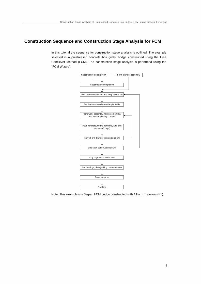
In this tutorial the sequence for construction stage analysis is outlined. The example
selected is a prestressed concrete box girder bridge constructed using the Free
Cantilever Method (FCM). The construction stage analysis is performed using the
“FCM Wizard”.
Note: This example is a 3-span FCM bridge constructed with 4 Form Travelers (FT).
Substructure construction Form traveler assembly
Substructure completion
Pier table construction and fixity device set
Set the form traveler on the pier table
Form work assembly, reinforcement bar
and tendon placing (7 days)
Pour concrete, curing concrete, and jack
tendons (5 days)
Move Form traveler to next segment
Side span construction (FSM)
Key segment construction
Set bearings, then jacking bottom tendon
Pave structure
Finishing
ADVANCED APPLICATIONS
2
In the construction stage analysis, the construction sequence given below should be
followed precisely. The construction stage analysis capability of MIDAS/Civil
comprises an activate/deactivate concept of Structure Groups, Boundary Groups and
Load Groups. The sequence of construction stage analysis for FCM is as follows:
1. Define material and section
2. Structure modeling
3. Define Structure Group
4. Define Boundary Group
5. Define Load Group
6. Input Load
7. Arrange tendons
8. Prestress tendons
9. Define time dependent material property
10. Perform structural analysis
11. Review results
Steps 2 to 8 are explained in “Construction stage analysis using FCM Wizard”. In this
tutorial, the procedure for analysis of a FCM bridge from steps 1 to 8, using general
functions will be explained. The procedure for steps 9 to 11 is identical to the one
given in “Construction stage analysis using FCM Wizard”, and will not be repeated in
this tutorial.
Construction Stage Analysis of Prestressed Concrete Box Bridge (FCM) using General Functions
3
Assign Working Environment
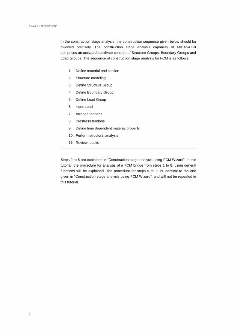
To perform a construction stage analysis for a FCM bridge, open a new file ( New
Project) and save ( Save) as „FCM General.mcb‟.
Assign the unit system as „kN‟ and „m‟. The unit system can be changed arbitrarily
during modeling, as per the convenience of the user.
File / New Project
File / Save (FCM General)
Tools / Unit System
Length> m ; Force>kN
Figure 1 Assign unit system
The unit system
selected can be
changed by clicking
on the unit selection
button in the Status
Bar located at the
bottom of screen.
ADVANCED APPLICATIONS
4
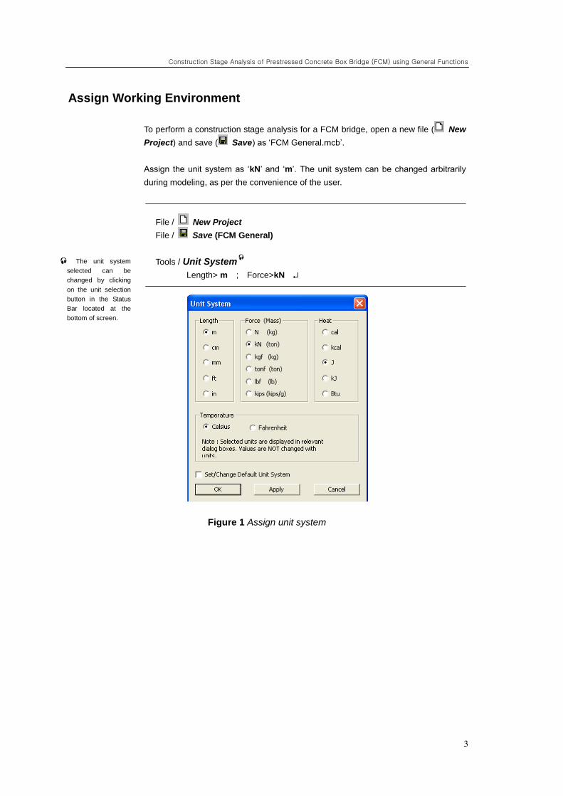
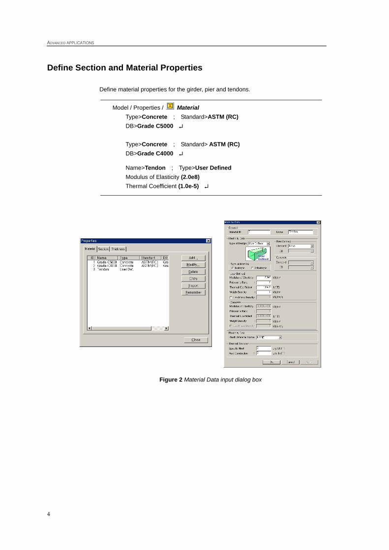
Define Section and Material Properties
Define material properties for the girder, pier and tendons.
Model / Properties / Material
Type>Concrete ; Standard>ASTM (RC)
DB>Grade C5000
Type>Concrete ; Standard> ASTM (RC)
DB>Grade C4000
Name>Tendon ; Type>User Defined
Modulus of Elasticity (2.0e8)
Thermal Coefficient (1.0e-5)
Figure 2 Material Data input dialog box
Construction Stage Analysis of Prestressed Concrete Box Bridge (FCM) using General Functions
5
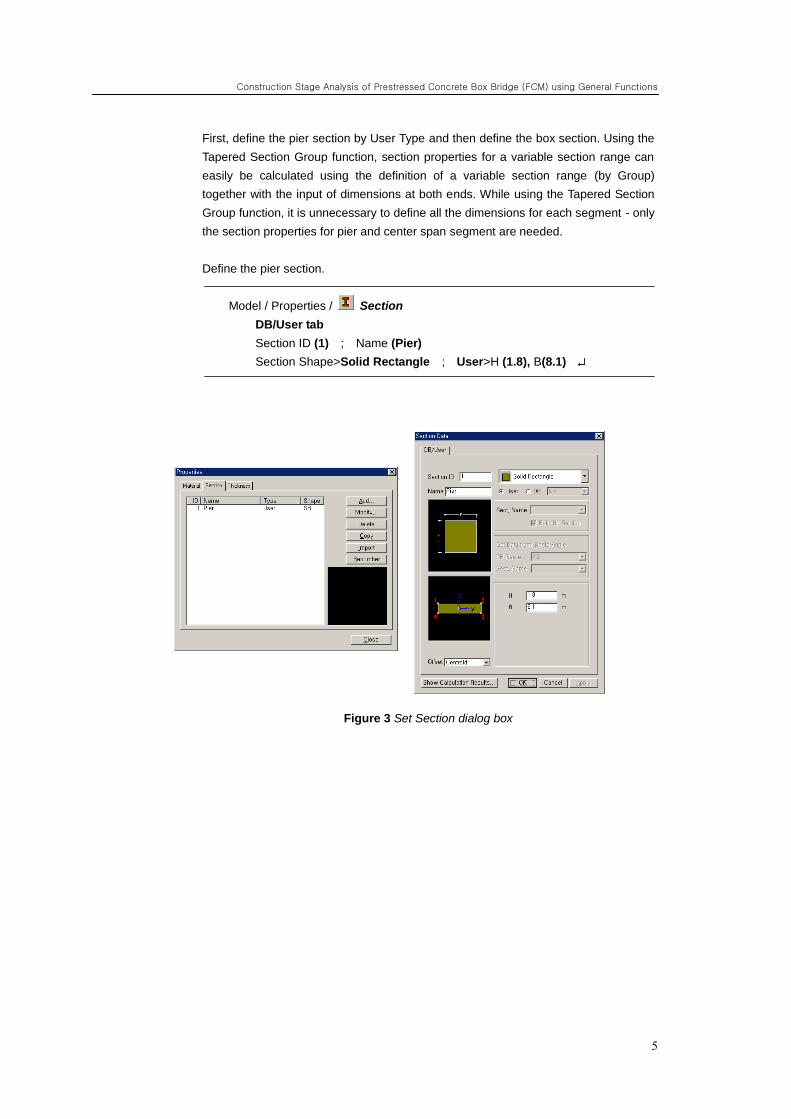
First, define the pier section by User Type and then define the box section. Using the
Tapered Section Group function, section properties for a variable section range can
easily be calculated using the definition of a variable section range (by Group)
together with the input of dimensions at both ends. While using the Tapered Section
Group function, it is unnecessary to define all the dimensions for each segment - only
the section properties for pier and center span segment are needed.
Define the pier section.
Model / Properties / Section
DB/User tab
Section ID (1) ; Name (Pier)
Section Shape>Solid Rectangle ; User>H (1.8), B(8.1)
Figure 3 Set Section dialog box
ADVANCED APPLICATIONS
6
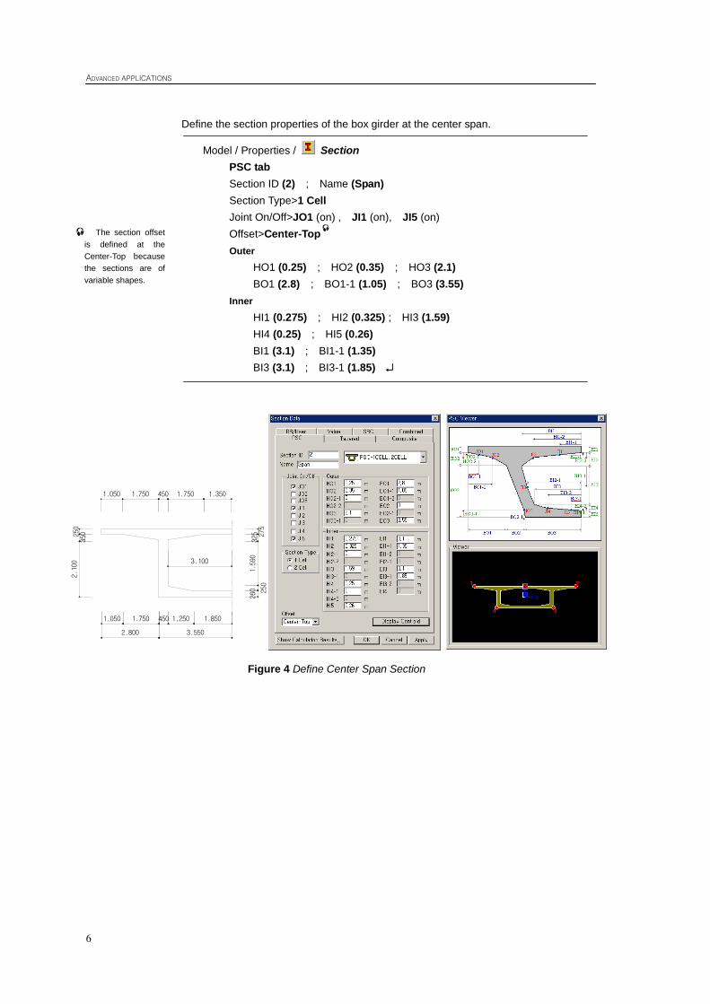
Define the section properties of the box girder at the center span.
Model / Properties / Section
PSC tab
Section ID (2) ; Name (Span)
Section Type>1 Cell
Joint On/Off>JO1 (on) , JI1 (on), JI5 (on)
Offset>Center-Top
Outer
HO1 (0.25) ; HO2 (0.35) ; HO3 (2.1)
BO1 (2.8) ; BO1-1 (1.05) ; BO3 (3.55)
Inner
HI1 (0.275) ; HI2 (0.325) ; HI3 (1.59)
HI4 (0.25) ; HI5 (0.26)
BI1 (3.1) ; BI1-1 (1.35)
BI3 (3.1) ; BI3-1 (1.85)
Figure 4 Define Center Span Section
The section offset
is defined at the
Center-Top because
the sections are of
variable shapes.
1.8501.250450
250
2.100
250
350
1.3501.7504501.7501.050
1.050 1.750
2.800 3.550
260
1.590
275
325
3.100
Construction Stage Analysis of Prestressed Concrete Box Bridge (FCM) using General Functions
7
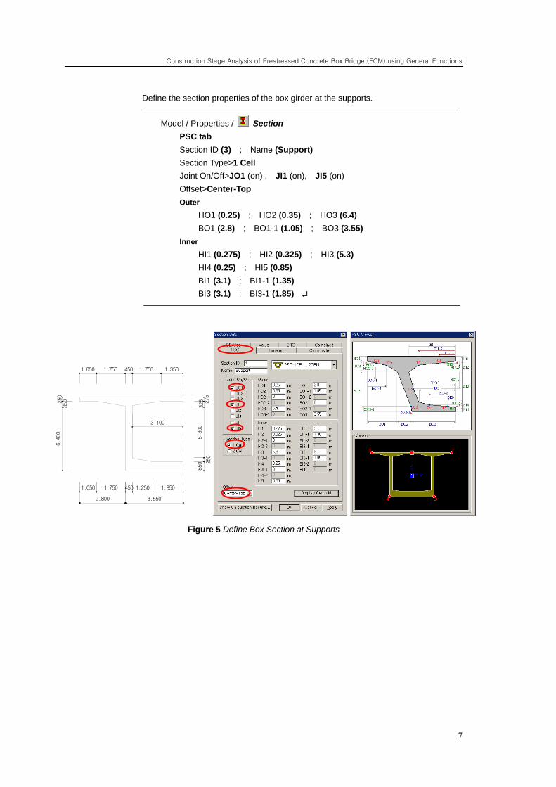
Define the section properties of the box girder at the supports.
Model / Properties / Section
PSC tab
Section ID (3) ; Name (Support)
Section Type>1 Cell
Joint On/Off>JO1 (on) , JI1 (on), JI5 (on)
Offset>Center-Top
Outer
HO1 (0.25) ; HO2 (0.35) ; HO3 (6.4)
BO1 (2.8) ; BO1-1 (1.05) ; BO3 (3.55)
Inner
HI1 (0.275) ; HI2 (0.325) ; HI3 (5.3)
HI4 (0.25) ; HI5 (0.85)
BI1 (3.1) ; BI1-1 (1.35)
BI3 (3.1) ; BI3-1 (1.85)
Figure 5 Define Box Section at Supports
1.8501.250450
250
6.400
250
350
1.3501.7504501.7501.050
1.050 1.750
2.800 3.550
850
5.300
275
325
3.100
ADVANCED APPLICATIONS
8
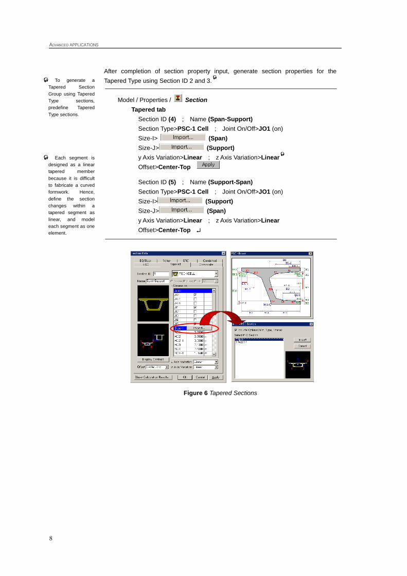
After completion of section property input, generate section properties for the
Tapered Type using Section ID 2 and 3.
Model / Properties / Section
Tapered tab
Section ID (4) ; Name (Span-Support)
Section Type>PSC-1 Cell ; Joint On/Off>JO1 (on)
Size-I> (Span)
Size-J> (Support)
y Axis Variation>Linear ; z Axis Variation>Linear
Offset>Center-Top
Section ID (5) ; Name (Support-Span)
Section Type>PSC-1 Cell ; Joint On/Off>JO1 (on)
Size-I> (Support)
Size-J> (Span)
y Axis Variation>Linear ; z Axis Variation>Linear
Offset>Center-Top
Figure 6 Tapered Sections
To generate a
Tapered Section
Group using Tapered
Type sections,
predefine Tapered
Type sections.
Each segment is
designed as a linear
tapered member
because it is difficult
to fabricate a curved
formwork. Hence,
define the section
changes within a
tapered segment as
linear, and model
each segment as one
element.
Construction Stage Analysis of Prestressed Concrete Box Bridge (FCM) using General Functions
9
Structural Modeling
Model FCM Bridge using general functions of MIDAS/Civil.
To perform construction stage analysis, construction stages must first be defined. In
MIDAS/Civil, there are two working modes - Base Stage mode and Construction
Stage mode.
In Base Stage mode, any structural model, load condition and boundary condition
can be defined, but the structural analysis is not performed. In Construction Stage
mode, the structural analysis is performed, but the structural model input data cannot
be modified or deleted except for the boundary conditions and load conditions.
Construction stages do not comprise of individual elements, boundary conditions or
load conditions, but comprise of Activation and Deactivation commands for the
Structure Group, Boundary Group and Load Group. In the Construction Stage mode,
the boundary conditions and load conditions included in the activated Boundary
Group and Load Group, respectively, can be modified or deleted.
In the analysis of FCM bridge, the loads that are applied during construction (tendon
prestress, form traveler and self-weight of the segments) are complicated. Hence, the
construction stages are predefined and then the load condition is defined in each
construction stage. The structural systems and boundary conditions are defined in
Base Stage mode.
The modeling procedure is as follows:
1. Prestressed concrete box girder modeling
2. Pier modeling
3. Define Time Dependent Material Property
4. Assign Structure Group
5. Assign Boundary Group and input boundary condition
6. Assign Load group
ADVANCED APPLICATIONS
10
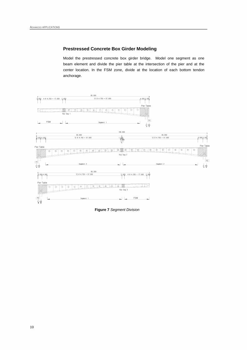
Prestressed Concrete Box Girder Modeling
Model the prestressed concrete box girder bridge. Model one segment as one
beam element and divide the pier table at the intersection of the pier and at the
center location. In the FSM zone, divide at the location of each bottom tendon
anchorage.
Figure 7 Segment Division
121110987654321
FSM 구간P2
FSM 구간
12 11 10 9 8 7 6 5 4 3 2 1
P1
85.000
3.00012 @ 4.750 = 57.0002.0004 @ 4.250 = 17.0002.000
85.000
12 @ 4.750 = 57.000 2.000 4 @ 4.250 = 17.000 2.000
13 14 15 16 17 18 19 20 21 22 23 24
P1
65.000
130.000
1.00012 @ 4.750 = 57.000
LC
131415161718192021222324
P2
65.000
1.00012 @ 4.750 = 57.000
Segment 1
4.000
2.100
4.0003.000
2.100Segment 2 Segment 2
Segment 1
2.100
2.100
3.0004.000
4.0003.000
Key Seg 1
주두부
주두부 주두부
주두부
Key Seg 2
Key Seg 3
Pier Table
FSM
Pier Table Pier Table
Pier Table
FSM
Construction Stage Analysis of Prestressed Concrete Box Bridge (FCM) using General Functions
11
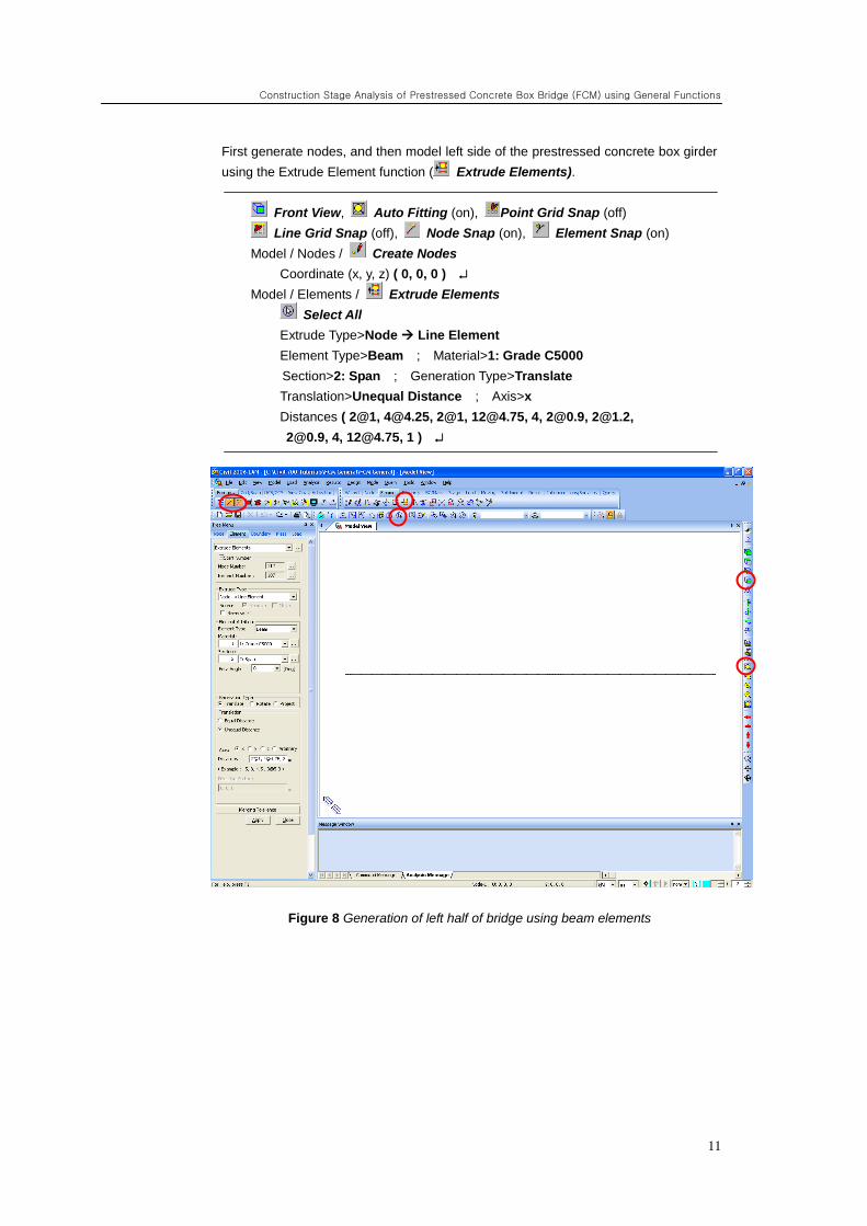
First generate nodes, and then model left side of the prestressed concrete box girder
using the Extrude Element function ( Extrude Elements).
Front View, Auto Fitting (on), Point Grid Snap (off)
Line Grid Snap (off), Node Snap (on), Element Snap (on)
Model / Nodes / Create Nodes
Coordinate (x, y, z) ( 0, 0, 0 )
Model / Elements / Extrude Elements
Select All
Extrude Type>Node Line Element
Element Type>Beam ; Material>1: Grade C5000
Section>2: Span ; Generation Type>Translate
Translation>Unequal Distance ; Axis>x
Distances ( 2@1, [email protected], 2@1, [email protected], 4, [email protected], [email protected],
[email protected], 4, [email protected], 1 )
Figure 8 Generation of left half of bridge using beam elements
ADVANCED APPLICATIONS
12
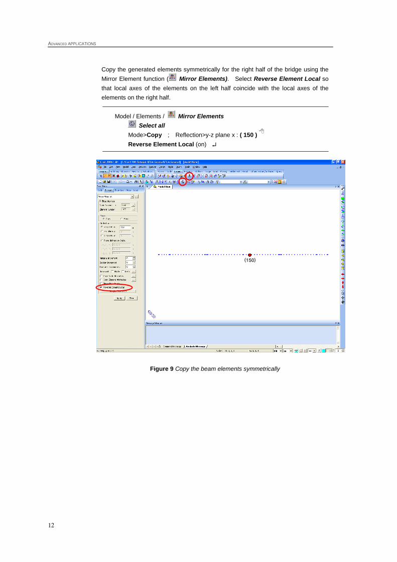
Copy the generated elements symmetrically for the right half of the bridge using the
Mirror Element function ( Mirror Elements). Select Reverse Element Local so
that local axes of the elements on the left half coincide with the local axes of the
elements on the right half.
Model / Elements / Mirror Elements
Select all
Mode>Copy ; Reflection>y-z plane x : ( 150 )
Reverse Element Local (on)
Figure 9 Copy the beam elements symmetrically
(150)
Construction Stage Analysis of Prestressed Concrete Box Bridge (FCM) using General Functions
13
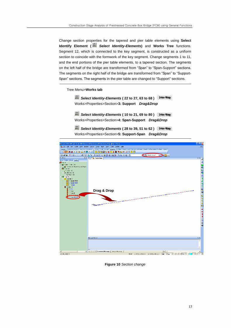
Change section properties for the tapered and pier table elements using Select
Identify Element ( Select Identity-Elements) and Works Tree functions.
Segment 12, which is connected to the key segment, is constructed as a uniform
section to coincide with the formwork of the key segment. Change segments 1 to 11,
and the end portions of the pier table elements, to a tapered section. The segments
on the left half of the bridge are transformed from “Span” to “Span-Support” sections.
The segments on the right half of the bridge are transformed from “Span” to “Support-
Span” sections. The segments in the pier table are changed to “Support” sections.
Tree Menu>Works tab
Select Identity-Elements ( 22 to 27, 63 to 68 )
Works>Properties>Section>3: Support Drag&Drop
Select Identity-Elements ( 10 to 21, 69 to 80 )
Works>Properties>Section>4: Span-Support Drag&Drop
Select Identity-Elements ( 28 to 39, 51 to 62 )
Works>Properties>Section>5: Support-Span Drag&Drop
Figure 10 Section change
EEE nnn ttt eee rrr KKK eee yyy
EEE nnn ttt eee rrr KKK eee yyy
EEE nnn ttt eee rrr KKK eee yyy
Drag & Drop
ADVANCED APPLICATIONS
14
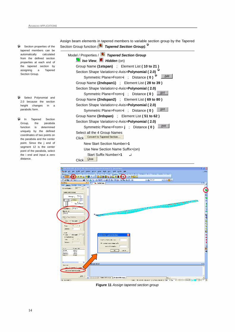
Assign beam elements in tapered members to variable section group by the Tapered
Section Group function ( Tapered Section Group).
Model / Properties / Tapered Section Group
Iso View, Hidden (on)
Group Name (1stspan) ; Element List ( 10 to 21 )
Section Shape Variation>z-Axis>Polynomial ( 2.0)
Symmetric Plane>From>i ; Distance ( 0 )
Group Name (2ndspan1) ; Element List ( 28 to 39 )
Section Shape Variation>z-Axis>Polynomial ( 2.0)
Symmetric Plane>From>j ; Distance ( 0 )
Group Name (2ndspan2) ; Element List ( 69 to 80 )
Section Shape Variation>z-Axis>Polynomial ( 2.0)
Symmetric Plane>From>i ; Distance ( 0 )
Group Name (3rdspan) ; Element List ( 51 to 62 )
Section Shape Variation>z-Axis>Polynomial ( 2.0)
Symmetric Plane>From> j ; Distance ( 0 )
Select all the 4 Group Names
Click
New Start Section Number>1
Use New Section Name Suffix>(on)
Start Suffix Number>1
Click
Figure 11 Assign tapered section group
Section properties of the
tapered members can be
automatically calculated
from the defined section
properties at each end of
the tapered section by
assigning a Tapered
Section Group.
Select Polynomial and
2.0 because the section
height changes in a
parabolic form.
In Tapered Section
Group, the parabola
function is determined
uniquely by the defined
coordinates of two points on
the parabola and the center
point. Since the j end of
segment 12 is the center
point of the parabola, select
the i end and input a zero
distance.
Construction Stage Analysis of Prestressed Concrete Box Bridge (FCM) using General Functions
15
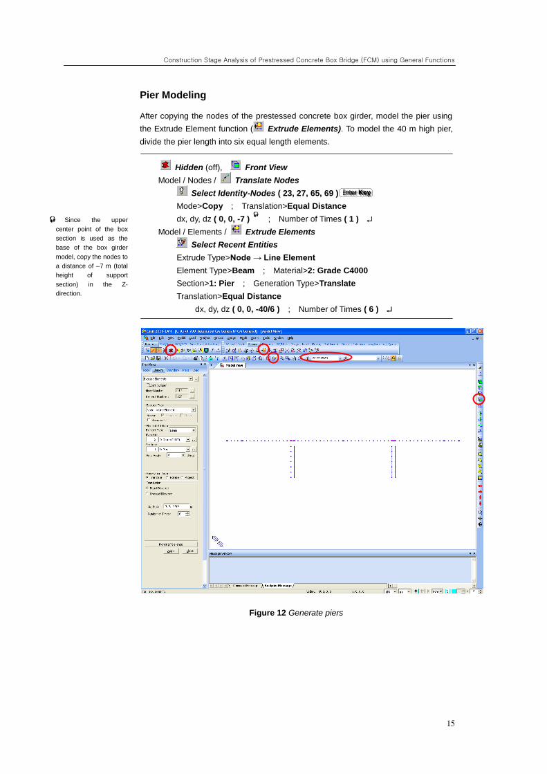
Pier Modeling
After copying the nodes of the prestessed concrete box girder, model the pier using
the Extrude Element function ( Extrude Elements). To model the 40 m high pier,
divide the pier length into six equal length elements.
Hidden (off), Front View
Model / Nodes / Translate Nodes
Select Identity-Nodes ( 23, 27, 65, 69 )
Mode>Copy ; Translation>Equal Distance
dx, dy, dz ( 0, 0, -7 )
; Number of Times ( 1 )
Model / Elements / Extrude Elements
Select Recent Entities
Extrude Type>Node → Line Element
Element Type>Beam ; Material>2: Grade C4000
Section>1: Pier ; Generation Type>Translate
Translation>Equal Distance
dx, dy, dz ( 0, 0, -40/6 ) ; Number of Times ( 6 )
Figure 12 Generate piers
Since the upper
center point of the box
section is used as the
base of the box girder
model, copy the nodes to
a distance of –7 m (total
height of support
section) in the Z-
direction.
EEE nnn ttt eee rrr KKK eee yyy
ADVANCED APPLICATIONS
16
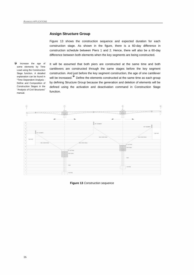
Assign Structure Group
Figure 13 shows the construction sequence and expected duration for each
construction stage. As shown in the figure, there is a 60-day difference in
construction schedule between Piers 1 and 2. Hence, there will also be a 60-day
difference between both elements when the key segments are being constructed.
It will be assumed that both piers are constructed at the same time and both
cantilevers are constructed through the same stages before the key segment
construction. And just before the key segment construction, the age of one cantilever
will be increased.
Define the elements constructed at the same time as each group
by defining Structure Group because the generation and deletion of elements will be
defined using the activation and deactivation command in Construction Stage
function.
Figure 13 Construction sequence
Increase the age of
some elements by Time
Load using the Construction
Stage function. A detailed
explanation can be found in
“Time Dependent Analysis -
Define and Composition of
Construction Stages in the
“Analysis of Civil Structures”
manual.
1112 10 9 8 7 6 5 4 3 2 1 1 2 3 4 5 6 7 8 9 10 11 12 12 11 10 9 8 7 6 5 4 3 2 1 1 2 3 4 5 6 7 8 9 10 11 12
A1
SEG (12DAY/SEG)
FSM PART
17
14
15
12
13
16
9
10
11
8
7
6
5
4
3
2
1
SEG (12DAY/SEG)
P1 P2 A2
FSM PART
PIER TABLE
PIER
FOOTING
F/T SETTING
KEY-SEGMENT
KEY-SEGMENT
KEY-SEGMENT
SEG (12DAY/SEG) SEG (12DAY/SEG)
PIER TABLE
PIER
FOOTING
F/T SETTING
18
CLOF PIER
CLOF PIER
Construction Stage Analysis of Prestressed Concrete Box Bridge (FCM) using General Functions
17
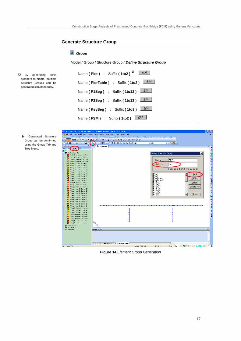
Generate Structure Group
Group
Model / Group / Structure Group / Define Structure Group
Name ( Pier ) ; Suffix ( 1to2 )
Name ( PierTable ) ; Suffix ( 1to2 )
Name ( P1Seg ) ; Suffix ( 1to12 )
Name ( P2Seg ) ; Suffix ( 1to12 )
Name ( KeySeg ) ; Suffix ( 1to3 )
Name ( FSM ) ; Suffix ( 1to2 )
Figure 14 Element Group Generation
By appending suffix
numbers to Name, multiple
Structure Groups can be
generated simultaneously.
Generated Structure
Group can be confirmed
using the Group Tab and
Tree Menu.
ADVANCED APPLICATIONS
18
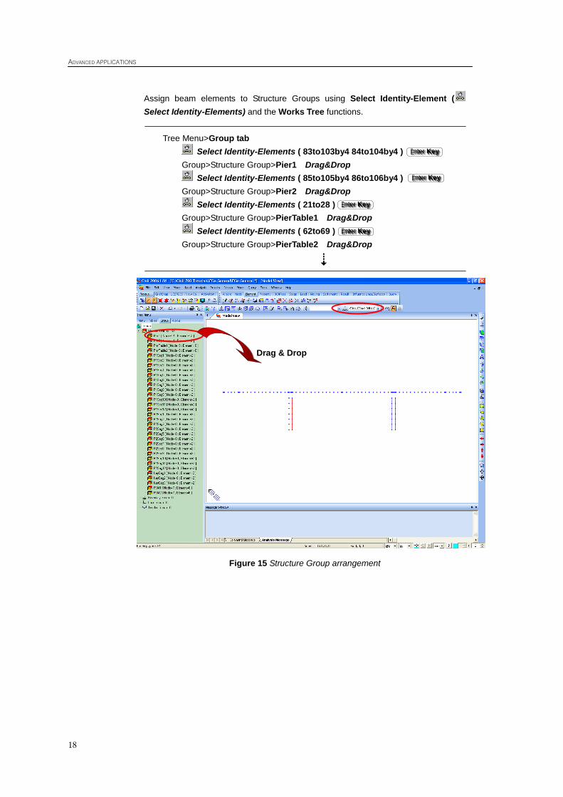
Assign beam elements to Structure Groups using Select Identity-Element (
Select Identity-Elements) and the Works Tree functions.
Tree Menu>Group tab
Select Identity-Elements ( 83to103by4 84to104by4 )
Group>Structure Group>Pier1 Drag&Drop
Select Identity-Elements ( 85to105by4 86to106by4 )
Group>Structure Group>Pier2 Drag&Drop
Select Identity-Elements ( 21to28 )
Group>Structure Group>PierTable1 Drag&Drop
Select Identity-Elements ( 62to69 )
Group>Structure Group>PierTable2 Drag&Drop
Figure 15 Structure Group arrangement
EEE nnn ttt eee rrr KKK eee yyy
EEE nnn ttt eee rrr KKK eee yyy
EEE nnn ttt eee rrr KKK eee yyy
EEE nnn ttt eee rrr KKK eee yyy
Drag & Drop
Construction Stage Analysis of Prestressed Concrete Box Bridge (FCM) using General Functions
19
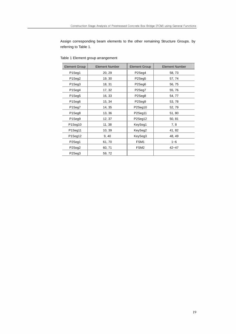
Assign corresponding beam elements to the other remaining Structure Groups. by
referring to Table 1.
Table 1 Element group arrangement
Element Group Element Number Element Group Element Number
P1Seg1 20, 29 P2Seg4 58, 73
P1Seg2 19, 30 P2Seg5 57, 74
P1Seg3 18, 31 P2Seg6 56, 75
P1Seg4 17, 32 P2Seg7 55, 76
P1Seg5 16, 33 P2Seg8 54, 77
P1Seg6 15, 34 P2Seg9 53, 78
P1Seg7 14, 35 P2Seg10 52, 79
P1Seg8 13, 36 P2Seg11 51, 80
P1Seg9 12, 37 P2Seg12 50, 81
P1Seg10 11, 38 KeySeg1 7, 8
P1Seg11 10, 39 KeySeg2 41, 82
P1Seg12 9, 40 KeySeg3 48, 49
P2Seg1 61, 70 FSM1 1~6
P2Seg2 60, 71 FSM2 42~47
P2Seg3 59, 72
ADVANCED APPLICATIONS
20
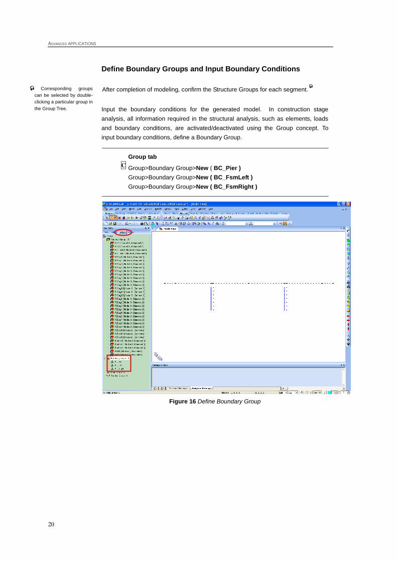
Define Boundary Groups and Input Boundary Conditions
After completion of modeling, confirm the Structure Groups for each segment.
Input the boundary conditions for the generated model. In construction stage
analysis, all information required in the structural analysis, such as elements, loads
and boundary conditions, are activated/deactivated using the Group concept. To
input boundary conditions, define a Boundary Group.
Group tab
Group>Boundary Group>New ( BC_Pier )
Group>Boundary Group>New ( BC_FsmLeft )
Group>Boundary Group>New ( BC_FsmRight )
Figure 16 Define Boundary Group
C
Corresponding groups
can be selected by double-
clicking a particular group in
the Group Tree.
Construction Stage Analysis of Prestressed Concrete Box Bridge (FCM) using General Functions
21
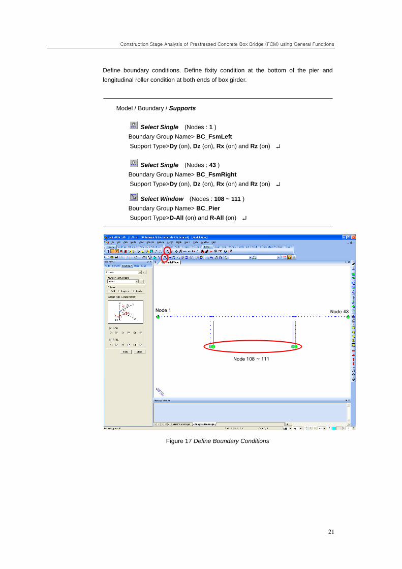
Define boundary conditions. Define fixity condition at the bottom of the pier and
longitudinal roller condition at both ends of box girder.
Model / Boundary / Supports
Select Single (Nodes : 1 )
Boundary Group Name> BC_FsmLeft
Support Type>Dy (on), Dz (on), Rx (on) and Rz (on)
Select Single (Nodes : 43 )
Boundary Group Name> BC_FsmRight
Support Type>Dy (on), Dz (on), Rx (on) and Rz (on)
Select Window (Nodes : 108 ~ 111 )
Boundary Group Name> BC_Pier
Support Type>D-All (on) and R-All (on)
Figure 17 Define Boundary Conditions
Node 108 ~ 111
Node 1 Node 43
ADVANCED APPLICATIONS
22
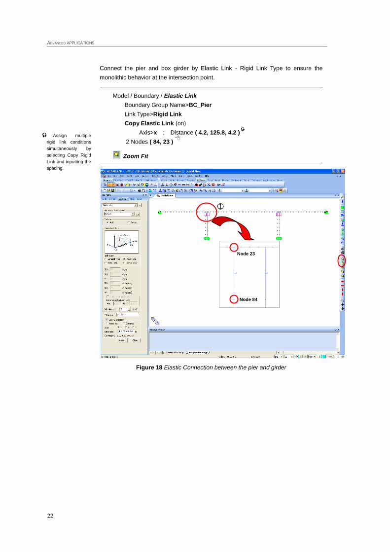
Connect the pier and box girder by Elastic Link - Rigid Link Type to ensure the
monolithic behavior at the intersection point.
Model / Boundary / Elastic Link
Boundary Group Name>BC_Pier
Link Type>Rigid Link
Copy Elastic Link (on)
Axis>x ; Distance ( 4.2, 125.8, 4.2 )
2 Nodes ( 84, 23 )
Zoom Fit
Figure 18 Elastic Connection between the pier and girder
Assign multiple
rigid link conditions
simultaneously by
selecting Copy Rigid
Link and inputting the
spacing.
①
Node 23
Node 84
Construction Stage Analysis of Prestressed Concrete Box Bridge (FCM) using General Functions
23
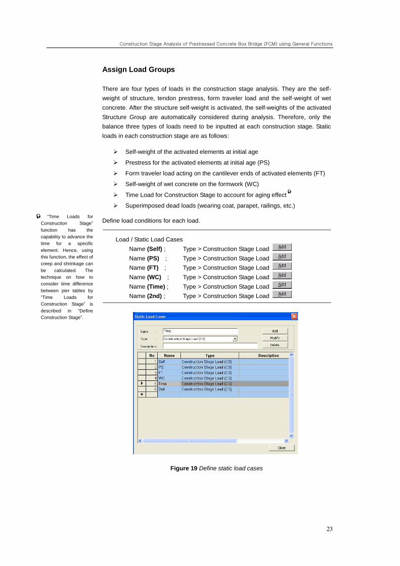
Assign Load Groups
There are four types of loads in the construction stage analysis. They are the self-
weight of structure, tendon prestress, form traveler load and the self-weight of wet
concrete. After the structure self-weight is activated, the self-weights of the activated
Structure Group are automatically considered during analysis. Therefore, only the
balance three types of loads need to be inputted at each construction stage. Static
loads in each construction stage are as follows:
Self-weight of the activated elements at initial age
Prestress for the activated elements at initial age (PS)
Form traveler load acting on the cantilever ends of activated elements (FT)
Self-weight of wet concrete on the formwork (WC)
Time Load for Construction Stage to account for aging effect
Superimposed dead loads (wearing coat, parapet, railings, etc.)
Define load conditions for each load.
Load / Static Load Cases
Name (Self) ; Type > Construction Stage Load
Name (PS) ; Type > Construction Stage Load
Name (FT) ; Type > Construction Stage Load
Name (WC) ; Type > Construction Stage Load
Name (Time) ; Type > Construction Stage Load
Name (2nd) ; Type > Construction Stage Load
Figure 19 Define static load cases
“Time Loads for
Construction Stage”
function has the
capability to advance the
time for a specific
element. Hence, using
this function, the effect of
creep and shrinkage can
be calculated. The
technique on how to
consider time difference
between pier tables by
“Time Loads for
Construction Stage” is
described in “Define
Construction Stage”.
ADVANCED APPLICATIONS
24
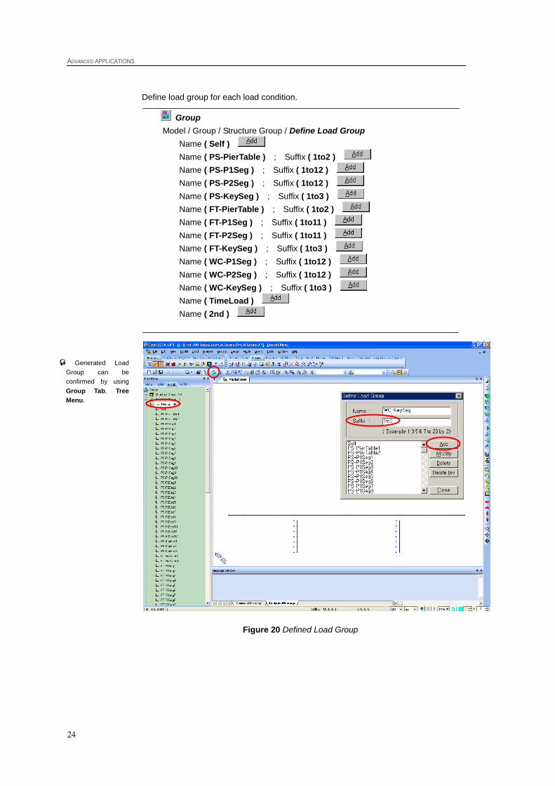
Define load group for each load condition.
Group
Model / Group / Structure Group / Define Load Group
Name ( Self )
Name ( PS-PierTable ) ; Suffix ( 1to2 )
Name ( PS-P1Seg ) ; Suffix ( 1to12 )
Name ( PS-P2Seg ) ; Suffix ( 1to12 )
Name ( PS-KeySeg ) ; Suffix ( 1to3 )
Name ( FT-PierTable ) ; Suffix ( 1to2 )
Name ( FT-P1Seg ) ; Suffix ( 1to11 )
Name ( FT-P2Seg ) ; Suffix ( 1to11 )
Name ( FT-KeySeg ) ; Suffix ( 1to3 )
Name ( WC-P1Seg ) ; Suffix ( 1to12 )
Name ( WC-P2Seg ) ; Suffix ( 1to12 )
Name ( WC-KeySeg ) ; Suffix ( 1to3 )
Name ( TimeLoad )
Name ( 2nd )
Figure 20 Defined Load Group
Generated Load
Group can be
confirmed by using
Group Tab, Tree
Menu.
Construction Stage Analysis of Prestressed Concrete Box Bridge (FCM) using General Functions
25
Define and Arrange Construction Stages
Define Construction Stages
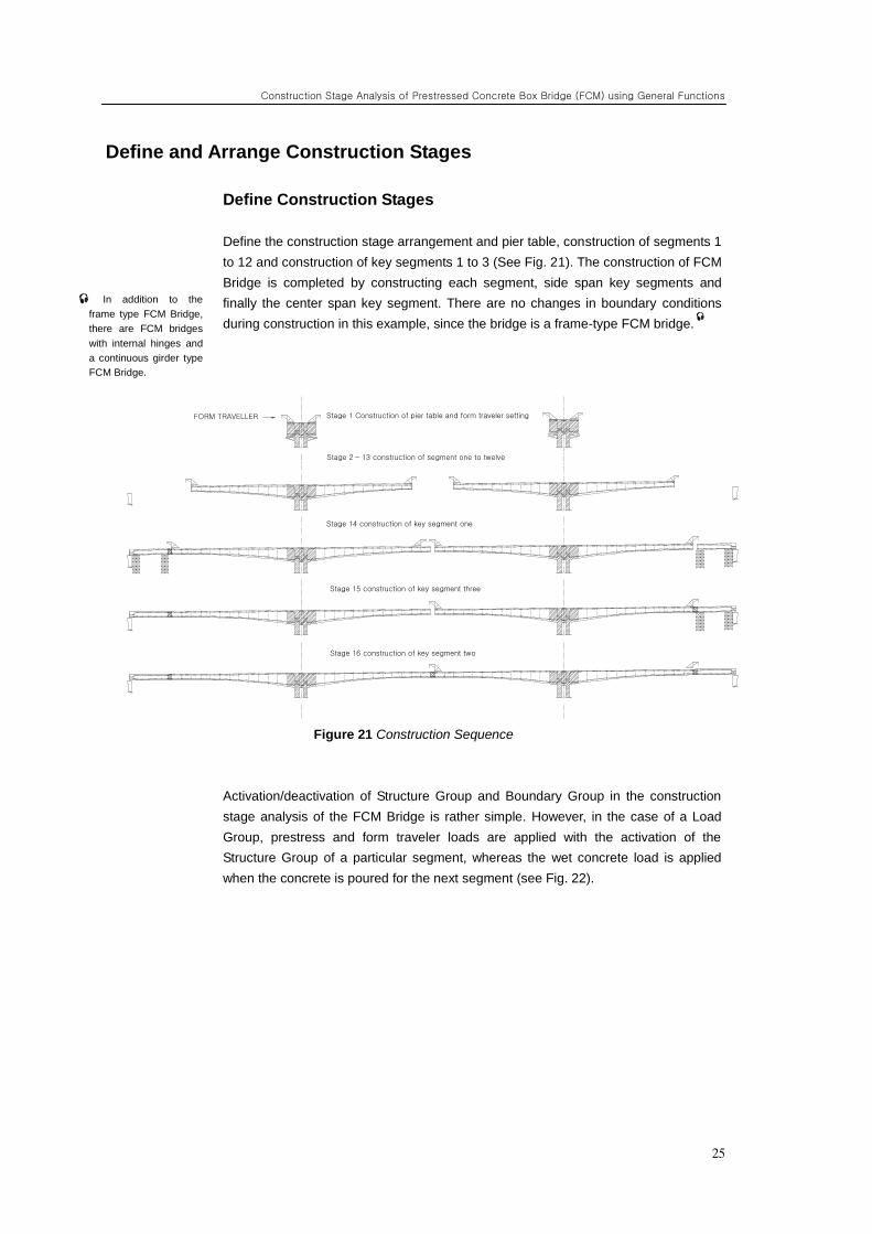
Define the construction stage arrangement and pier table, construction of segments 1
to 12 and construction of key segments 1 to 3 (See Fig. 21). The construction of FCM
Bridge is completed by constructing each segment, side span key segments and
finally the center span key segment. There are no changes in boundary conditions
during construction in this example, since the bridge is a frame-type FCM bridge.
Figure 21 Construction Sequence
Activation/deactivation of Structure Group and Boundary Group in the construction
stage analysis of the FCM Bridge is rather simple. However, in the case of a Load
Group, prestress and form traveler loads are applied with the activation of the
Structure Group of a particular segment, whereas the wet concrete load is applied
when the concrete is poured for the next segment (see Fig. 22).
In addition to the
frame type FCM Bridge,
there are FCM bridges
with internal hinges and
a continuous girder type
FCM Bridge.
FORM TRAVELLER "Stage 1" 주두부 시공 및 F/T 설치
"Stage 2~13" 세그먼트 1~12 시공
"Stage 14" Key Seg. 1 체결
"Stage 15" Key Seg. 3 체결
"Stage 16" Key Seg. 2 체결
Stage 1 Construction of pier table and form traveler setting
Stage 2 – 13 construction of segment one to twelve
Stage 14 construction of key segment one
Stage 15 construction of key segment three
Stage 16 construction of key segment two
ADVANCED APPLICATIONS
26
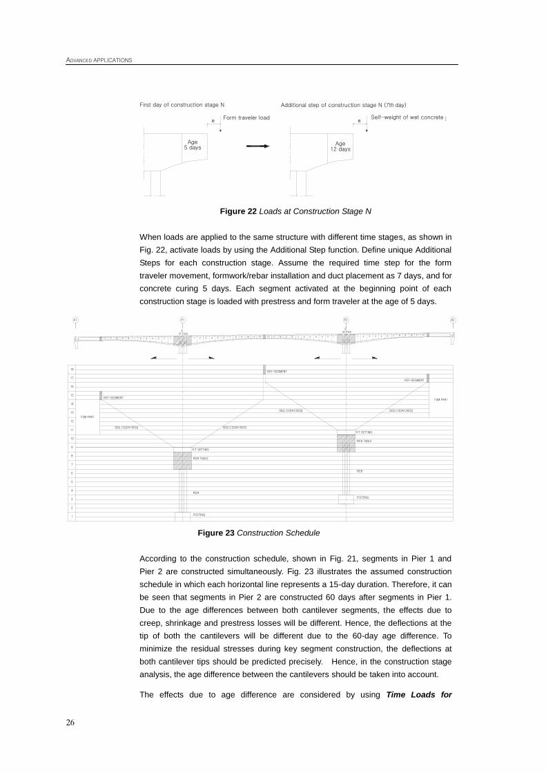
Figure 22 Loads at Construction Stage N
When loads are applied to the same structure with different time stages, as shown in
Fig. 22, activate loads by using the Additional Step function. Define unique Additional
Steps for each construction stage. Assume the required time step for the form
traveler movement, formwork/rebar installation and duct placement as 7 days, and for
concrete curing 5 days. Each segment activated at the beginning point of each
construction stage is loaded with prestress and form traveler at the age of 5 days.
Figure 23 Construction Schedule
According to the construction schedule, shown in Fig. 21, segments in Pier 1 and
Pier 2 are constructed simultaneously. Fig. 23 illustrates the assumed construction
schedule in which each horizontal line represents a 15-day duration. Therefore, it can
be seen that segments in Pier 2 are constructed 60 days after segments in Pier 1.
Due to the age differences between both cantilever segments, the effects due to
creep, shrinkage and prestress losses will be different. Hence, the deflections at the
tip of both the cantilevers will be different due to the 60-day age difference. To
minimize the residual stresses during key segment construction, the deflections at
both cantilever tips should be predicted precisely. Hence, in the construction stage
analysis, the age difference between the cantilevers should be taken into account.
The effects due to age difference are considered by using Time Loads for
1112 10 9 8 7 6 5 4 3 2 1 1 2 3 4 5 6 7 8 9 10 11 12 12 11 10 9 8 7 6 5 4 3 2 1 1 2 3 4 5 6 7 8 9 10 11 12
A1
SEG (12DAY/SEG)
FSM PART
17
14
15
12
13
16
9
10
11
8
7
6
5
4
3
2
1
SEG (12DAY/SEG)
P1 P2 A2
FSM PART
PIER TABLE
PIER
FOOTING
F/T SETTING
KEY-SEGMENT
KEY-SEGMENT
KEY-SEGMENT
SEG (12DAY/SEG) SEG (12DAY/SEG)
PIER TABLE
PIER
FOOTING
F/T SETTING
18
CLOF PIER
CLOF PIER
e 굳지 않은 콘크리트의 자중e작업차하중
시공단계 N의 first day 시공단계 N의 additional step (7th day)
재령 5일 재령 12일
First day of construction stage N
Form traveler load
Age 5 days
Additional step of construction stage N (7th day)
Self-weight of wet concrete
Age 12 days
Construction Stage Analysis of Prestressed Concrete Box Bridge (FCM) using General Functions
27
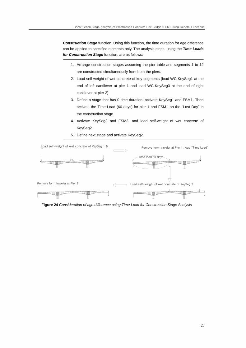
Construction Stage function. Using this function, the time duration for age difference
can be applied to specified elements only. The analysis steps, using the Time Loads
for Construction Stage function, are as follows:
1. Arrange construction stages assuming the pier table and segments 1 to 12
are constructed simultaneously from both the piers.
2. Load self-weight of wet concrete of key segments (load WC-KeySeg1 at the
end of left cantilever at pier 1 and load WC-KeySeg3 at the end of right
cantilever at pier 2)
3. Define a stage that has 0 time duration, activate KeySeg1 and FSM1. Then
activate the Time Load (60 days) for pier 1 and FSM1 on the “Last Day” in
the construction stage.
4. Activate KeySeg3 and FSM3, and load self-weight of wet concrete of
KeySeg2.
5. Define next stage and activate KeySeg2.
Figure 24 Consideration of age difference using Time Load for Construction Stage Analysis
굳지 않은 Key Seg.1, 3의 자중 재하교각 1 캔틸레버의 F/T 해체, 시간하중 재하
시간하중 60일
교각 2 캔틸레버의 F/T 해체 굳지 않은 Key Seg.2의 자중 재하
Load self-weight of wet concrete of KeySeg 1 & 3
Remove form traveler at Pier 2
Remove form traveler at Pier 1, load “Time Load”
Time load 60 days
Load self-weight of wet concrete of KeySeg 2

ADVANCED APPLICATIONS
28
The summary for the construction stages in terms of activation/deactivation of the
Structure, Load and Boundary Group at each construction stage is as follows.
1. Construction stage 1
Activate Structure Group for the pier and pier table
Activate Boundary Group (BC_Pier) for the pier and pier table
1st day: Activate prestress, form traveler load and self-weight
7th
day: Activate self-weight of wet concrete (segment 1)
2. Construction stage 2
Activate segment 1
1st day: Deactivate form traveler load and self-weight of wet concrete;
activate form traveler load and prestress
7th
day: Activate self-weight of the wet concrete (segment 2)
3. Construction stage 3-12: same as step (2)
4. Construction stage 13
Activate segment 12
1st day: Deactivate form traveler load and self-weight of wet concrete;
activate form traveler load and prestress
20th
day: Activate self-weight of the wet concrete (key segments 1 and 3)
5. Construction stage 14
Activate KeySeg 1 and FSM1
1st day: Deactivate form traveler load at pier 1 and self-weight of wet
concrete at KeySeg 1; activate prestress
Last day: activate time load for FSM1
6. Construction stage 15
Activate KeySeg 3, FSM3
1st day: Deactivate self-weight of the wet concrete of KeySeg 3; activate
prestress and self-weight of wet concrete of KeySeg 2
7. Construction stage 16
Activate KeySeg 2
1st day: deactivate form traveler load and self-weight of wet concrete;
activate prestress
8. Construction stage 17
1st day: activate superimposed dead load
Construction Stage Analysis of Prestressed Concrete Box Bridge (FCM) using General Functions
29
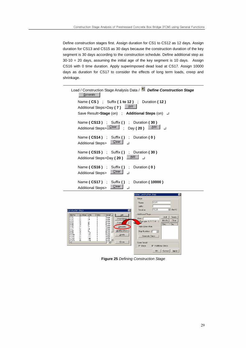
Define construction stages first. Assign duration for CS1 to CS12 as 12 days. Assign
duration for CS13 and CS15 as 30 days because the construction duration of the key
segment is 30 days according to the construction schedule. Define additional step as
30-10 = 20 days, assuming the initial age of the key segment is 10 days. Assign
CS16 with 0 time duration. Apply superimposed dead load at CS17. Assign 10000
days as duration for CS17 to consider the effects of long term loads, creep and
shrinkage.
Load / Construction Stage Analysis Data / Define Construction Stage
Name ( CS ) ; Suffix ( 1 to 12 ) ; Duration ( 12 )
Additional Steps>Day ( 7 )
Save Result>Stage (on) ; Additional Steps (on)
Name ( CS13 ) ; Suffix ( ) ; Duration ( 30 )
Additional Steps> ; Day ( 20 )
Name ( CS14 ) ; Suffix ( ) ; Duration ( 0 )
Additional Steps>
Name ( CS15 ) ; Suffix ( ) ; Duration ( 30 )
Additional Steps>Day ( 20 )
Name ( CS16 ) ; Suffix ( ) ; Duration ( 0 )
Additional Steps>
Name ( CS17 ) ; Suffix ( ) ; Duration ( 10000 )
Additional Steps>
Figure 25 Defining Construction Stage
ADVANCED APPLICATIONS
30
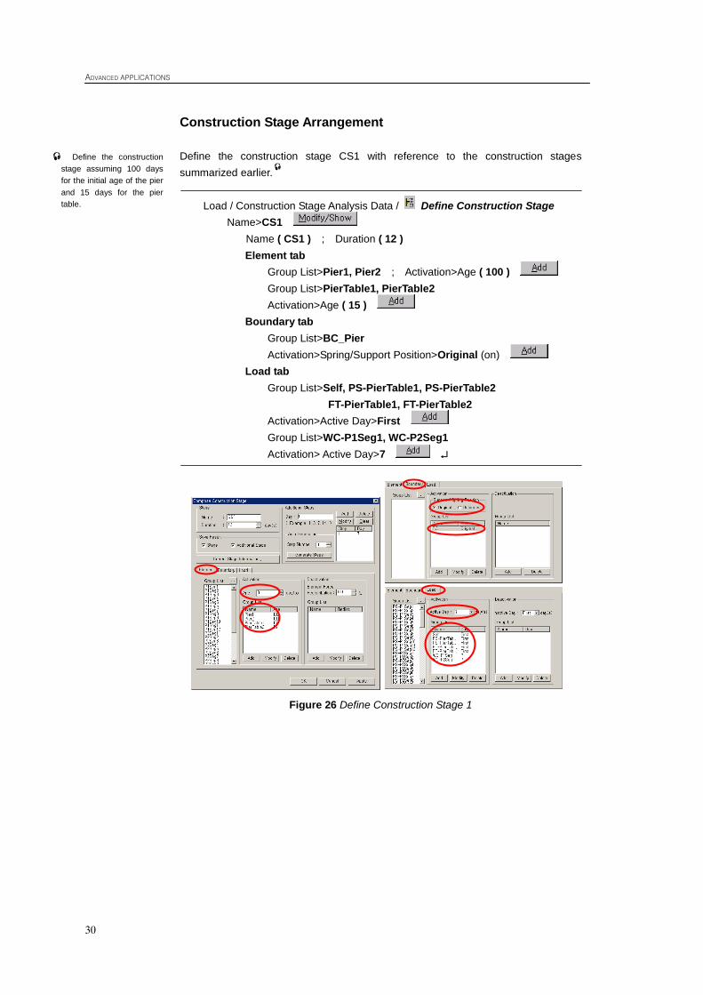
Construction Stage Arrangement
Define the construction stage CS1 with reference to the construction stages
summarized earlier.
Load / Construction Stage Analysis Data / Define Construction Stage
Name>CS1
Name ( CS1 ) ; Duration ( 12 )
Element tab
Group List>Pier1, Pier2 ; Activation>Age ( 100 )
Group List>PierTable1, PierTable2
Activation>Age ( 15 )
Boundary tab
Group List>BC_Pier
Activation>Spring/Support Position>Original (on)
Load tab
Group List>Self, PS-PierTable1, PS-PierTable2
FT-PierTable1, FT-PierTable2
Activation>Active Day>First
Group List>WC-P1Seg1, WC-P2Seg1
Activation> Active Day>7
Figure 26 Define Construction Stage 1
Define the construction
stage assuming 100 days
for the initial age of the pier
and 15 days for the pier
table.
Construction Stage Analysis of Prestressed Concrete Box Bridge (FCM) using General Functions
31
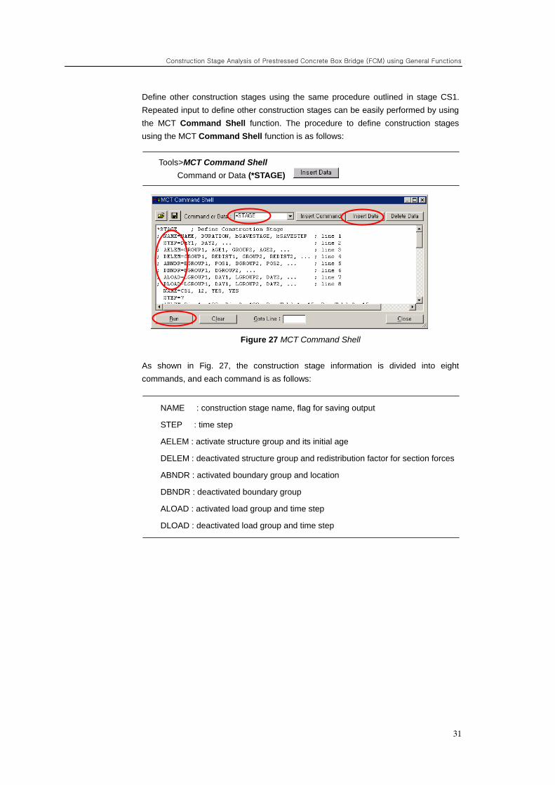
Define other construction stages using the same procedure outlined in stage CS1.
Repeated input to define other construction stages can be easily performed by using
the MCT Command Shell function. The procedure to define construction stages
using the MCT Command Shell function is as follows:
Tools>MCT Command Shell
Command or Data (*STAGE)
Figure 27 MCT Command Shell
As shown in Fig. 27, the construction stage information is divided into eight
commands, and each command is as follows:
NAME : construction stage name, flag for saving output
STEP : time step
AELEM : activate structure group and its initial age
DELEM : deactivated structure group and redistribution factor for section forces
ABNDR : activated boundary group and location
DBNDR : deactivated boundary group
ALOAD : activated load group and time step
DLOAD : deactivated load group and time step
ADVANCED APPLICATIONS
32
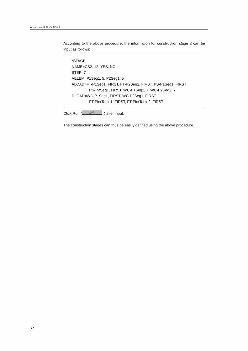
According to the above procedure, the information for construction stage 2 can be
input as follows:
*STAGE
NAME=CS2, 12, YES, NO
STEP=7
AELEM=P1Seg1, 5, P2Seg1, 5
ALOAD=FT-P1Seg1, FIRST, FT-P2Seg1, FIRST, PS-P1Seg1, FIRST
PS-P2Seg1, FIRST, WC-P1Seg2, 7, WC-P2Seg2, 7
DLOAD=WC-P1Seg1, FIRST, WC-P2Seg1, FIRST
FT-PierTable1, FIRST, FT-PierTable2, FIRST
Click Run ( ) after input.
The construction stages can thus be easily defined using the above procedure.
Construction Stage Analysis of Prestressed Concrete Box Bridge (FCM) using General Functions
33
Load Input
Input loads for each construction stage. Construction stage loads consist of form
traveler, wet concrete, self-weight of segments, prestress, time load and
superimposed load. Input construction stage load as following sequences.
1. Self-weight of structure
2. Form traveler
3. Wet concrete
4. Prestress
5. Time load
6. Superimposed load
Input the self-weight first. To automatically load the self-weight of the generated
structure, define self-weight of the structure and load at CS1.
Load / Self Weight
Load Case Name>Self
Load Group Name>Self
Self Weight Factor>Z (-1)
ADVANCED APPLICATIONS
34
Input the form traveler load. The form traveler load is assumed to be a 800 kN
vertical load with a 2000 kN-m bending moment about the y-axis, applied at the tip of
the cantilever.
Once the stage mode is selected, the Structure Groups, Load Groups and Boundary
Groups assigned to the current stage are automatically activated, and the loads can
be easily entered. The loads are inputted at each construction stage using the Stage
Toolbar.
Stage>CS1
Iso View
Load / Nodal Loads
Select Single ( Node : 21 )
Load Case Name>FT ; Load Group Name>FT-PierTable1
Options>Add ; FZ ( -800 ), MY ( -2000 )
Select Single ( Node : 29 )
Load Case Name>FT ; Load Group Name>FT-PierTable1
Options>Add ; FZ ( -800 ), MY ( 2000 )
Select Single ( Node : 71 )
Load Case Name>FT ; Load Group Name>FT-PierTable2
Options>Add ; FZ ( -800 ), MY ( -2000 )
Select Single ( Node : 63 )
Load Case Name>FT ; Load Group Name>FT-PierTable2
Options>Add ; FZ ( -800 ), MY ( 2000 )
Construction Stage Analysis of Prestressed Concrete Box Bridge (FCM) using General Functions
35
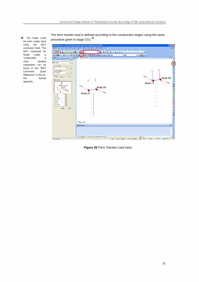
The form traveler load is defined according to the construction stages using the same
procedure given in stage CS1.
Figure 28 Form Traveler Load Input
The loads could
be more easily input
using the MCT
command Shell. The
MCT command for
Nodal Loads is
“CONLOAD”. A
more detailed
explanation can be
found in the “MCT
Command Quick
Reference” in the on-
line manual
appendix.
Node 21
Node 29
Node 71
Node 63
ADVANCED APPLICATIONS
36
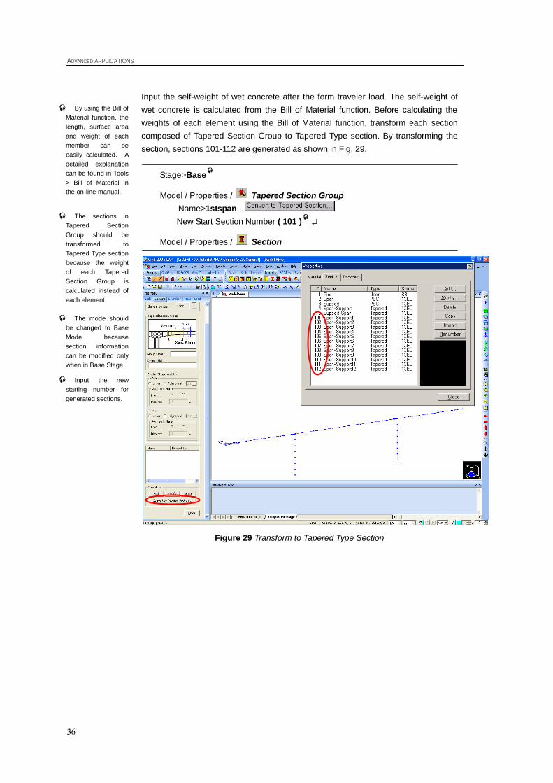
Input the self-weight of wet concrete after the form traveler load. The self-weight of
wet concrete is calculated from the Bill of Material function. Before calculating the
weights of each element using the Bill of Material function, transform each section
composed of Tapered Section Group to Tapered Type section. By transforming the
section, sections 101-112 are generated as shown in Fig. 29.
Stage>Base
Model / Properties / Tapered Section Group
Name>1stspan
New Start Section Number ( 101 )
Model / Properties / Section
Figure 29 Transform to Tapered Type Section
By using the Bill of
Material function, the
length, surface area
and weight of each
member can be
easily calculated. A
detailed explanation
can be found in Tools
> Bill of Material in
the on-line manual.
The sections in
Tapered Section
Group should be
transformed to
Tapered Type section
because the weight
of each Tapered
Section Group is
calculated instead of
each element.
The mode should
be changed to Base
Mode because
section information
can be modified only
when in Base Stage.
Input the new
starting number for
generated sections.
Construction Stage Analysis of Prestressed Concrete Box Bridge (FCM) using General Functions
37
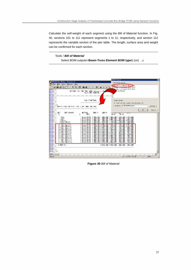
Calculate the self-weight of each segment using the Bill of Material function. In Fig.
30, sections 101 to 111 represent segments 1 to 11, respectively, and section 112
represents the variable section of the pier table. The length, surface area and weight
can be confirmed for each section.
Tools / Bill of Material
Select BOM outputs>Beam-Truss Element BOM type1 (on)
Figure 30 Bill of Material
ADVANCED APPLICATIONS
38
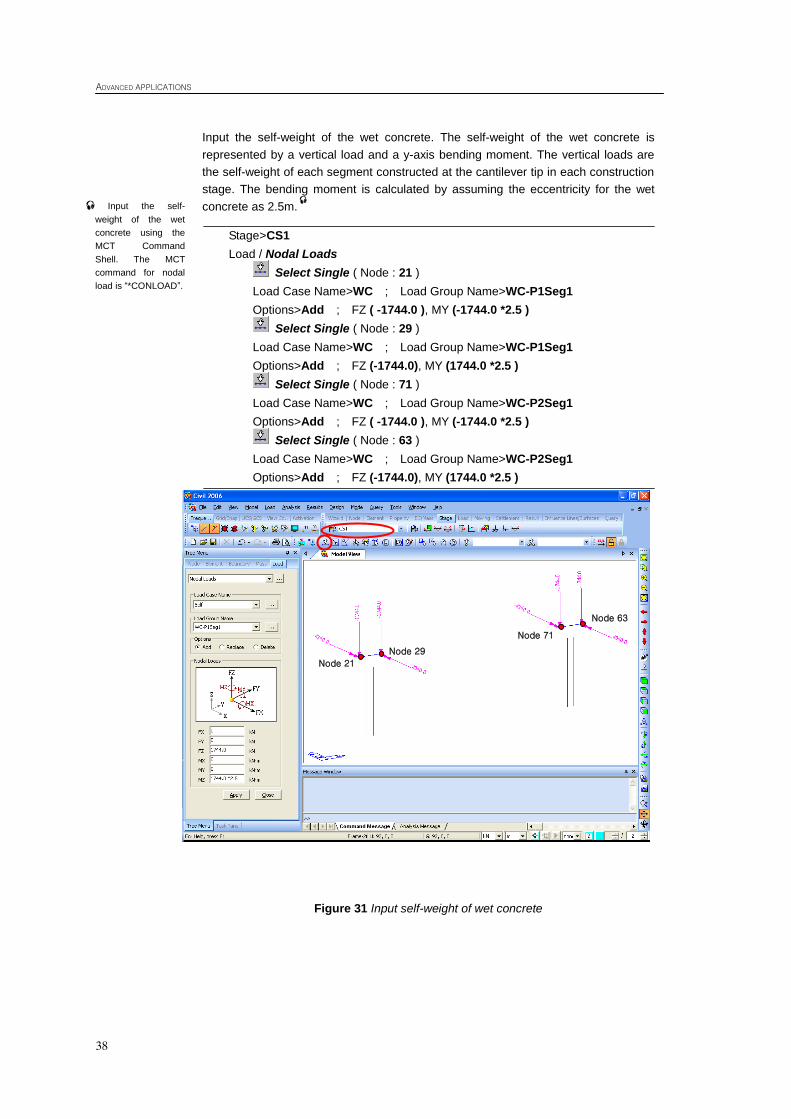
Input the self-weight of the wet concrete. The self-weight of the wet concrete is
represented by a vertical load and a y-axis bending moment. The vertical loads are
the self-weight of each segment constructed at the cantilever tip in each construction
stage. The bending moment is calculated by assuming the eccentricity for the wet
concrete as 2.5m.
Stage>CS1
Load / Nodal Loads
Select Single ( Node : 21 )
Load Case Name>WC ; Load Group Name>WC-P1Seg1
Options>Add ; FZ ( -1744.0 ), MY (-1744.0 *2.5 )
Select Single ( Node : 29 )
Load Case Name>WC ; Load Group Name>WC-P1Seg1
Options>Add ; FZ (-1744.0), MY (1744.0 *2.5 )
Select Single ( Node : 71 )
Load Case Name>WC ; Load Group Name>WC-P2Seg1
Options>Add ; FZ ( -1744.0 ), MY (-1744.0 *2.5 )
Select Single ( Node : 63 )
Load Case Name>WC ; Load Group Name>WC-P2Seg1
Options>Add ; FZ (-1744.0), MY (1744.0 *2.5 )
Figure 31 Input self-weight of wet concrete
Input the self-
weight of the wet
concrete using the
MCT Command
Shell. The MCT
command for nodal
load is “*CONLOAD”.
Node 21
Node 29
Node 71
Node 63
Construction Stage Analysis of Prestressed Concrete Box Bridge (FCM) using General Functions
39
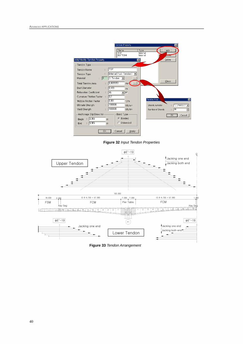
Input prestress. From the defined starting, inflection and ending point, the optimum
tendon profile can be generated automatically within the program. Three dimensional
tendon coordinates about the x-axis define the tendon profile. Before defining the
tendon coordinates, the tendon properties should be input.
Stage>Base
Load/ Prestress Loads / Tendon Property
Tendon Name ( TOP ) ; Tendon Type>Internal
Material>3: tendon
Total Tendon Area (0.0026353)
or
Tendon Area>15.2mm(0.6")
Number of Tendon Area (19)
Duct Diameter (0.103) ; Relaxation Coefficient (45)
Curvature Friction Factor (0.2) ; Wobble Friction Factor (0.001)
Ultimate Strength (1900000) ; Yield Strength (1600000)
Load Type>Post-Tension
Anchorage Slip>Begin (0.006) ; End (0.006)
Tendon Name ( BOTTOM ) ; Tendon Type>Internal
Material>3: tendon
Total Tendon Area (0.0026353)
or
Tendon Area>15.2mm(0.6")
Number of Tendon Area (19)
Duct Diameter (0.103) ; Relaxation Coefficient (45)
Curvature Friction Factor (0.3) ; Wobble Friction Factor (0.0066)
Ultimate Strength (1900000) ; Yield Strength (1600000)
Load Type>Post-Tension
Anchorage Slip>Begin (0.006) ; End (0.006)
The relaxation
Coefficient is a constant
used in Magura‟s
formula. It is generally
used to calculate
relaxation effects of the
tendon material over
time. It can be assumed
to be 10 for normal
relaxation strand and 45
for low relaxation
strand. A detailed
explanation of the
Relaxation Coefficient
can be found under
“Prestress Loss” in the
Analysis of Civil
Structures.
ADVANCED APPLICATIONS
40
Figure 32 Input Tendon Properties
Figure 33 Tendon Arrangement
150.000
19.000 12 @ 4.750 = 57.000
5 6 7 8 9 10 11 12
1.000
φ6˝-19
P1
2.000 12 @ 4.750 = 57.000 7.000 7.000
12 11 10 9 8 7 6 5 4 3 2 1 1 2 3 4
상 부 강 연 선
하 부 강 연 선
CL
φ6˝-19 φ6˝-19
일단긴장
양단긴장
일단긴장
양단긴장
일단긴장
주두부FCM 구간 FCM 구간FSM 구간Key Seg Key Seg
Upper Tendon
Lower Tendon
Jacking one end Jacking both end
FSM FCM FCM Pier Table
Jacking one end Jacking one end
Jacking both end
Construction Stage Analysis of Prestressed Concrete Box Bridge (FCM) using General Functions
41
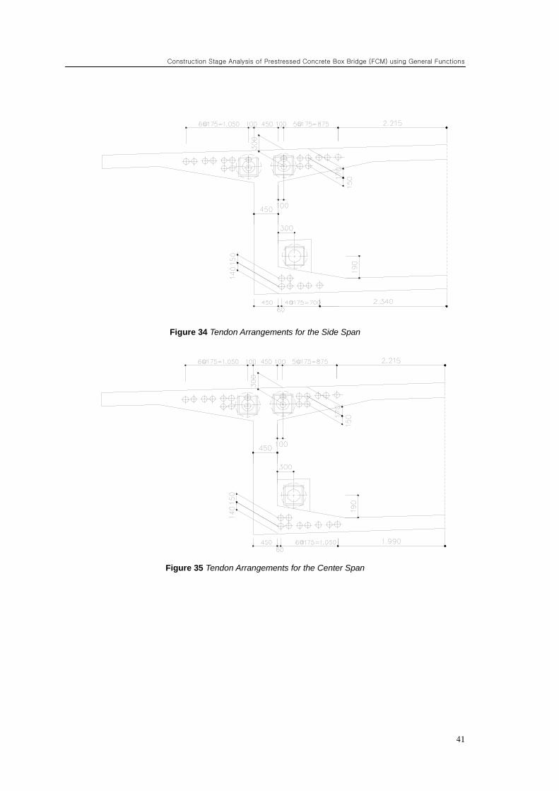
Figure 34 Tendon Arrangements for the Side Span
Figure 35 Tendon Arrangements for the Center Span
ADVANCED APPLICATIONS
42
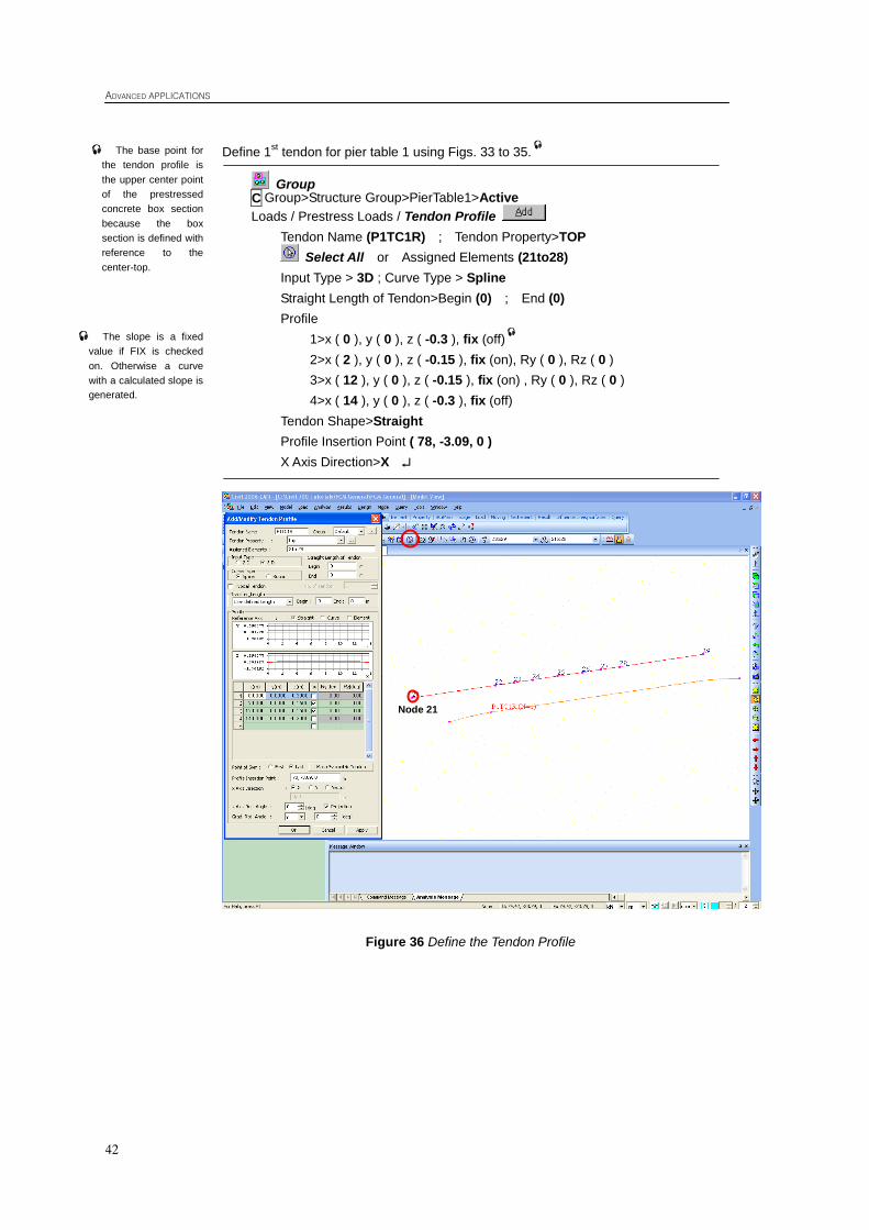
Define 1st tendon for pier table 1 using Figs. 33 to 35.
Group Group>Structure Group>PierTable1>Active
Loads / Prestress Loads / Tendon Profile
Tendon Name (P1TC1R) ; Tendon Property>TOP
Select All or Assigned Elements (21to28)
Input Type > 3D ; Curve Type > Spline
Straight Length of Tendon>Begin (0) ; End (0)
Profile
1>x ( 0 ), y ( 0 ), z ( -0.3 ), fix (off)
2>x ( 2 ), y ( 0 ), z ( -0.15 ), fix (on), Ry ( 0 ), Rz ( 0 )
3>x ( 12 ), y ( 0 ), z ( -0.15 ), fix (on) , Ry ( 0 ), Rz ( 0 )
4>x ( 14 ), y ( 0 ), z ( -0.3 ), fix (off)
Tendon Shape>Straight
Profile Insertion Point ( 78, -3.09, 0 )
X Axis Direction>X
Figure 36 Define the Tendon Profile
C
The slope is a fixed
value if FIX is checked
on. Otherwise a curve
with a calculated slope is
generated.
The base point for
the tendon profile is
the upper center point
of the prestressed
concrete box section
because the box
section is defined with
reference to the
center-top.
Node 21
Construction Stage Analysis of Prestressed Concrete Box Bridge (FCM) using General Functions
43
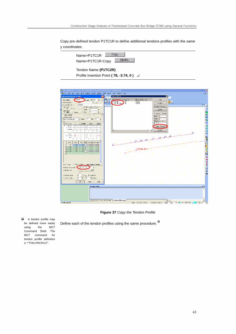
Copy pre-defined tendon P1TC1R to define additional tendons profiles with the same
y coordinates.
Name>P1TC1R
Name>P1TC1R-Copy
Tendon Name (P1TC2R)
Profile Insertion Point ( 78, -3.74, 0 )
Figure 37 Copy the Tendon Profile
Define each of the tendon profiles using the same procedure.
A tendon profile may
be defined more easily
using the MCT
Command Shell. The
MCT command for
tendon profile definition
is “*TDN-PROFILE”.
ADVANCED APPLICATIONS
44
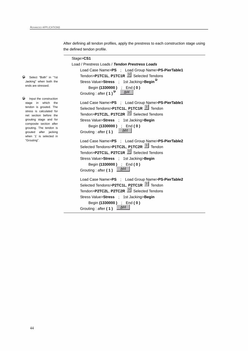
After defining all tendon profiles, apply the prestress to each construction stage using
the defined tendon profile.
Stage>CS1
Load / Prestress Loads / Tendon Prestress Loads
Load Case Name>PS ; Load Group Name>PS-PierTable1
Tendon>P1TC1L, P1TC1R Selected Tendons
Stress Value>Stress ; 1st Jacking>Begin
Begin (1330000 ) ; End ( 0 )
Grouting : after ( 1 )
Load Case Name>PS ; Load Group Name>PS-PierTable1
Selected Tendons>P1TC1L, P1TC1R Tendon
Tendon>P1TC2L, P1TC2R Selected Tendons
Stress Value>Stress ; 1st Jacking>Begin
Begin (1330000 ) ; End ( 0 )
Grouting : after ( 1 )
Load Case Name>PS ; Load Group Name>PS-PierTable2
Selected Tendons>P1TC2L, P1TC2R Tendon
Tendon>P2TC1L, P2TC1R Selected Tendons
Stress Value>Stress ; 1st Jacking>Begin
Begin (1330000 ) ; End ( 0 )
Grouting : after ( 1 )
Load Case Name>PS ; Load Group Name>PS-PierTable2
Selected Tendons>P2TC1L, P2TC1R Tendon
Tendon>P2TC2L, P2TC2R Selected Tendons
Stress Value>Stress ; 1st Jacking>Begin
Begin (1330000 ) ; End ( 0 )
Grouting : after ( 1 )
Select “Both” in “1st
Jacking” when both the
ends are stressed.
Input the construction
stage in which the
tendon is grouted. The
stress is calculated for
net section before the
grouting stage and for
composite section after
grouting. The tendon is
grouted after jacking
when „1‟ is selected in
“Grouting”.
Construction Stage Analysis of Prestressed Concrete Box Bridge (FCM) using General Functions
45
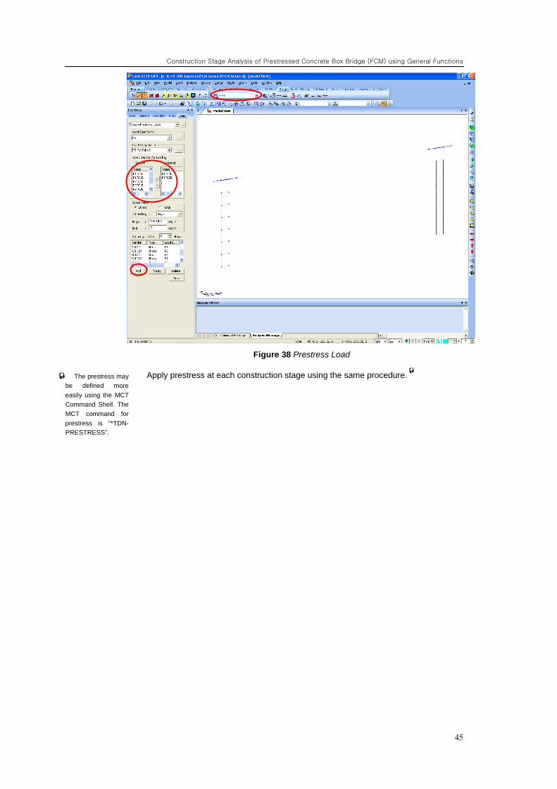
Figure 38 Prestress Load
Apply prestress at each construction stage using the same procedure.
The prestress may
be defined more
easily using the MCT
Command Shell. The
MCT command for
prestress is “*TDN-
PRESTRESS”.
ADVANCED APPLICATIONS
46
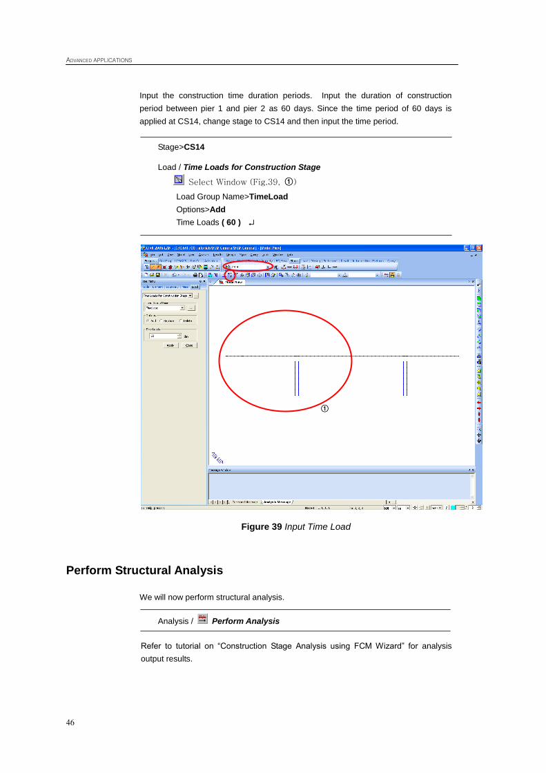
Input the construction time duration periods. Input the duration of construction
period between pier 1 and pier 2 as 60 days. Since the time period of 60 days is
applied at CS14, change stage to CS14 and then input the time period.
Stage>CS14
Load / Time Loads for Construction Stage
Select Window (Fig.39, ①)
Load Group Name>TimeLoad
Options>Add
Time Loads ( 60 )
Figure 39 Input Time Load
Perform Structural Analysis
We will now perform structural analysis.
Analysis / Perform Analysis
Refer to tutorial on “Construction Stage Analysis using FCM Wizard” for analysis
output results.
①