Embed Size (px)
Citation preview
A 1966 Conference Paper
Free-Convection Effects Inside Tubes of Flat-Plate Solar Collectors
n . I qba l , Department of Mechanical Engineering, The University of British Columbia, Vancouver 8, B. C.
An e x p e r i m e n t a l a n d t h e o r e t i c a l s t u d y o f t h e
ef fec ts o f f ree c o n v e c t i o n s u p e r i m p o s e d o n fo r ced flow in i n c l i n e d t u b e s is m a d e . T h e t h e o r e t i c a l a n a l y s i s c o n s i d e r e d fu l l y deve loped l a m i n a r
f low u n d e r u n i f o r m h e a t f lux a n d c o n s t a n t p r e s - s u r e g r a d i e n t . S o l u t i o n s fo r ve loc i t y a n d t e m p e r a - t u r e e q u a t i o n s h a v e b e e n o b t a i n e d b y p e r t u r b a - t i o n a n a l y s i s , in t e r m s o f p o w e r ser ies o f R a y l e i g h n u m b e r . N u s s e l t n u m b e r h a s b e e n e v a l u a t e d o n b u l k t e m p e r a t u r e d i f f e rence bas i s a n d a m a x i - m u m va lue o f i t a p p e a r s to l ie b e t w e e n 20 deg a n d 60 deg o f t u b e i n c l i n a t i o n . An e x p e r i m e n t a l s t u d y was d o n e fo r 45 deg t u b e i n c l i n a t i o n a n d a lso for ve r t i c a l p o s i t i o n .
W ITH the limited amount, of intensity of solar irradiation, the flow velocities in the tubes of
flat-plate solar collector are usually kept small, to a t ta in higher tempera ture differences between water inlet and outlet. Densi ty differences arise as a result of this tempera ture difference, and under the influence of earth 's gravi ta t ion 'd force, free-convection effects result. When a fluid in a horizontal tube is heated, the buoyancy forces cause movement of the fluid upwards
at the sides and downwards at the center. The effect of this, combined with tha t of the forced flow, set up forward-moving spirals. This helical flow pat tern is basically similar to flow through a round curved pipe 4, 5 or flow through a pipe rotat ing about an axis perpendicular to its ownL
Numerous studies of combined free and forced con- vection in vertical tubes are available 2, 3, 8, 9, z2, 14 Combined free and forced convection in horizontal tubes has received little attention. In references 7, ~3. ~5. ~s this case is examined for uniform wall temperature. Mor ton 17 carried out a theoretical analysis of com- bined free and forced convection in a horizontal tube under uniform heat flux and, Ede 6 reported an experi- mental investigation for the same. The case of inclined tubes has been studied theoretically by Iqbal and StachiewicziL
In a solar-energy application our interest is to de- terndne the heat-transfer rates from an inclined fiat- plate collector and /or to determine the op t imum inclination at which the heat transfer rate will be maxi- nl U 111.
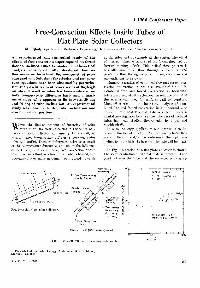
In Fig. 1 a section of a flat-plate collector is shown. The solar irradiation on the fiat plate is uniform. I f the bond between the tube and the collector plate is as-
Solar Radiation ~ ~ 1 ~
Fro. I---A flat-plate solar collector.
Flow Mixing I00 Honeycomb ~ /
T= Four Thermocouples . ~ Equally Spaced ~
2= S t a n d a r d S t e a m - , ~ , o ~ Lagging - ~ ' / ~
/ ~ / ' ~ 3 . L_ Ni- Cr Wire ~ / ~ 0.025" clio. ,o ~ ~ \ \ 40' long
~ / ~ " ~ Test S e c t i o n
/ ~ ~ Brass Tube / / O.O. 0.75" ==
/ / l.O 0.59" ~- Flow S t r a i g h t ner
I' long
Fro. 2--Test piece arrangement. I I ZO
FIG. 3--Nusselt number versus Rayleigb number.
I I I I t l I I I l [ I I DATA ON WATER
x 45 ° Tube Pos i t ion
o 90 = ,,
X X X
o o nll°l¢ o o o
. : o ' : ..o
Tube Length 6 FT. I ns ide R a d i u s 0.59 IN.
L I I I L t l IOO
Y NeA x
I IOOO
Presented at the Solar Energy Conference, Boston, Mass., March 21-23, 1966.
Vol. 10, No. 4, 1966 207
N O M E N C L A T U R E
R o m a n Le t t e r S y m b o l s
NRa NRe p = p* q =
A = axial temperature gradient (assumed constant), Ot/Ox, °F/ft .
a = tube radius in feet cp = specific heat of fluid at constant pressure,
Btu/ lb °F. g = acceleration due to gravity, ft/sec 2. g~, g~, go = components of acceleration due to gravity
in three coordinate directions, ft/sec 2. h = q / ( T , , - %) = heat transfer coefficient for fully
developed flow based on bulk temperature differ- ence, Btu/sec ft 2 °F.
N a , = ~gAa4 /v ~, Grashof number, dimensionless. N N u = 2 a h / k , Nusselt number dimensionless. N p , = c p g / k , Prandtl number, dimensionless.
Nor X Npr , Rayleigh number, dimensionless. 2aUo/~ Reynolds number, dimensionless. static fluid pressure, lb/f tL p / p U o ~, dimenseionless pressure wall heat flux density, average over the circum- ference Btu/sec/f t 2.
R = r / a , radial distance from the center line of the tube, dimensionless.
= radial distance in cylindrical coordinate system, measured from the center line of the tube, ft.
T = temperature of the fluid at any point, °F. Tb = bulk temperature of the fluid at any section, °F. To = temperature of the tube wall at beginning of the
fully developed flow, °F. T* = - ( T ~ - T ) / A a , difference between the wall
temperature and any point of the fluid at the same section, dimensionless
Tb* = - - ( T ~ -- T b ) / A a , difference between the wall temperature and bulk temperature of the fluid at the same section, dimensionless.
U0 = average axial velocity at entrance to heat trans- fer section.
v = velocity of a fluid particle, ft/sec. v, = fluid velocity measured along the radial coordi-
nate of tube, ft/sec. v~ = fluid velocity measured along the x-axis of tube,
ft/sec, ve = angular velocity of fluid measured along the
angular coordinate of tube, ft/sec. V~ = v J U o , axial velocity, dimensionless V , = v~/Uo , radial velocity, dimensionless Ve = vo/Uo , angular velocity, dimensionless x = axial coordinate of the tube measured in upward
direction (direction of flow), ft.
Greek Le t t e r S y m b o l s
= tube inclination measured from the horizontal position, degrees.
= volumetric coefficient of thermal expansion of the fluid, 1/°F.
A = difference between two points O ~ 1 O 1 a ~
V 2 = - - -b - Or "4- r2 Or ~ r O0 2
= thermal conductivity of fluid, Btu/see sq ft, °F/ft .
0 = angular position in cylindrical coordinate sys- tem, measured from the top point of the tube circumference, degrees.
= dynamic viscosity of fluid, lb/f t see. = kinematic viscosity of fluid, ft2/sec.
p = mass density of the fluid, Ib secVfO. tt~ = mass density of the fluid at wall, lb seeVfO. ¢ = Stokes stream function, dimensionless
S u b s c r i p t s
0, 1, 2--refer to zero, 1st, and 2nd order perturbation. 0, 1, 2--refer to points at various positions along the
axis of the tube.
sumed perfect , and the t he rma l c o n d u c t i v i t y of the p la te and t ube m a t e r i a l is much higher t h a n t h a t of the fluid, t hen the energy abso rbed can be a p p r o x i m a t e d to the case of un i fo rm hea t flux a round the tube .
E x p e r i m e n t a l A n a l y s i s
T h e a im of the exper imen t was to s imu la t e the con- d i t ions of a single tube of a solar collector, 6 ft long t h a t receives energy fal l ing on a 6-in. wide s t r ip of p la te . T a k i n g a va lue of abou t 300 B t u / h r ft 2, of solar i r r ad i a t i on on ear th , the to ta l energy received per t ube is abou t 1000 B t u / h r or a b o u t 300 w a t t s / h r . I n t he presen t s t u d y a 6-ft long brass t u b e 0.75 in. out - side d i ame te r and 0.59 in. inside d i a m e t e r was insu- l a t ed f rom outs ide b y a t he rmose t t i ng pa in t . A 40-ft long Ni -Cr wire of 0.025-in. d i a m e t e r and 33.72 ohms to t a l res is tance was coiled a round the t ube to p rov ide un i fo rm hea t flux. S t a n d a r d s t eam-p ipe insu la t ion was used for lagging of the tes t section. W i t h o u t wa te r flow and by plugging bo th the ends of the tes t section, hea t - loss ana lyses t h rough the lagging were car r ied out. A p lo t of hea t loss aga ins t t e m p e r a t u r e difference be-
tween t ube surface and the a m b i e n t air was ob t a ined and u t i l ized in the ana lys i s of the t e s t -da t a .
T h e genera l a r r a n g e m e n t of t he t es t sec t ion is shown in Fig. 2. W a t e r flow ra tes were de t e rmine d b y t em- pe ra tu re me a su re me n t s a t the inlet and the out le t . T h e resul ts of the d a t a for 45 deg and 90 deg t u b e inc l ina t ion are given in Fig. 3.
T h e o r e t i c a l A n a l y s i s
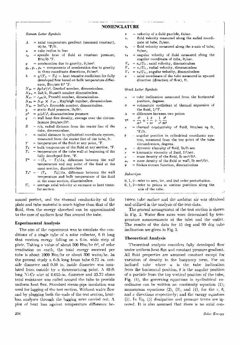
Theore t i ca l ana lys i s considers ful ly deve loped flow unde r un i fo rm hea t flux and cons t an t pressure g rad ien t . Al l fluid p roper t i e s are assumed cons t an t except for v a r i a t i o n of dens i ty in the b u o y a n c y te rm. F o r an incl ined tube where a is the t ube inc l ina t ion f rom the hor i zon ta l posi t ion, 0 is the angu la r pos i t ion of a par t ic le f rom the t o p ver t i ca l pos i t ion of t he tube , Fig. (4), t he govern ing equa t ions in eycl indr icM co- o rd ina tes can be w r i t t e n as: con t inu i ty equa t ion (1); m o m e n t u m equa t ions (2), (3), and (4), for the r, 0, and x d i rec t ions respec t ive ly ; and the energy equa t ion (5). I n Eq. (5) d i s s ipa t ion and pressure t e rms are ig- nored. I t is also assumed t h a t there is no axial con-
208 S o l a r E n e r g g
duction of heat. Equations (1) to (5) are to be non- dimensionalized with the help of the parameters (6), (7), (8), and (9).
The resulting dimensionless continuity equation can be satisfied by a stream function expressed as in Eqs. (10a) and (10b).
When Eqs. (2) and (3) are non-dimensionalized and pressure terms are eliminated by simultaneous differ- entiation, the resulting expression is Eq. 11.
By a similar method equations (13) are obtained by eliminating pressure from Eq. (4).
+ = o O)
FIG. 4--Coordinate system.
J
Fully Developed Lommor Flow
g
EnLarged Tube Section
2.
)
(3)
f'c "oo • .,ray.. ~ = T (.S)
(6)
P'= t ' /p,:
- P-, % 00o4 "o0
N~
The dimensionless energy equation can be written as in Eq. (14).
Equations (11) through (14) are to be solved by boundary conditions given in Eqs. (15a), (15b), and (15c). No exact solutions of Eqs. (11) through (14) are so far available. These equations can however be linearized by perturbation expansions, and then solved by separation of variables technique. The three de- pendent variables ~, V,, and T* are expanded by a power series in Rayleigh number, N~, and the ex- pansions are Eqs. (16), (17), and (18). The resulting equations have been solved. The details of the solu- tions and the final expressions which are very lengthy are however, available in reference 10.
Calculat ion of Nussel t Number
Having obtained an analytical expressiou for the temperature T, the rate of heat transfer can now be evaluated.
The dimensionless parameter indicative of the rate of energy convection from a surface is the Nussel~ number, and is expressed as Eq. (19) and (20).
N~
Vol. 10, No. ~, 1966 209
= 2 \ K . 'oO "b~. I~'o~, bo ~ =
o ¢d:: r ,= l "aK g. ~B - -
( . ~
2 K i
=- X"
~'='f,, + N~% + N ~ ' t ' : , - - (~e.,,( % =o)
= N ~
T ,~ = + ~T, , Nm,.T~ , - -
Discussion The experimental data in Fig. 3 indicates that the
heat-transfer rates are not discernibly different for the two tube inclinations studied, i.e. 45 deg and the vertical position. This experiment was performed at the 5IcGill University Brace Research Institute, Barbados. Because of pressure fluctuations in the water line, the flow rates could not be held uniform in the absence of a constant head tank. Also the power fluctuations were also quite substantial and in the absence of any suitable control equipment, the energy input was varying. These factors lead us to believe that considerably more refined experiments under controlled conditions are desirable.
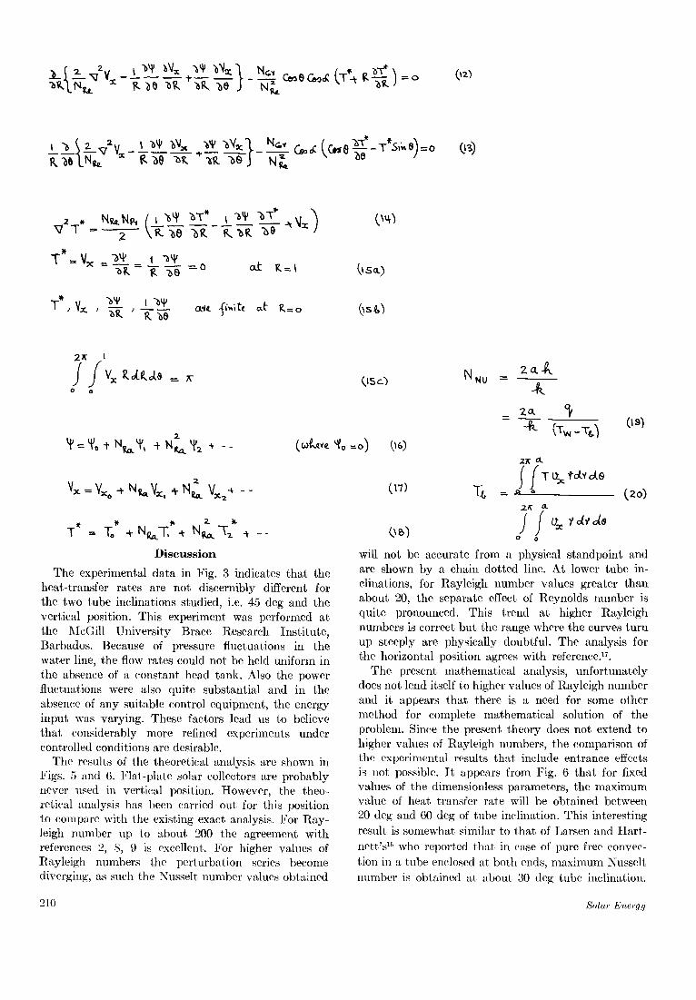
The results of the theoretical analysis are shown in Figs. 5 and 6. Flat-plate solar collectors are probably ncvcr used in vertical position. However, the theo- retical analysis has been carried out for this position to compare with the existing exact analysis. For Ray- leigh number up to about 200 the agreement with references 2, 8, 9 is excellent. For higher values of Rayleigh numbers the perturbation series become diverging, as such the Nusselt number values obtained
(,tsc') N NU z 2.
A _ 2 0 , c~
0 s )
2 R o .
c,7 .S ;. = ( 2 0 )
2 ~ O.
(.~) o o
will not be accurate from a physical standpoint and are shown by a chain dotted line. At lower tube in- clinations, for R~yleigh number values greater than about 20, the separate effect of Reynolds number is quite pronounced. This trend at higher Rayleigh numbers is correct but the range where the curves turn up steeply are physically doubtful. The analysis for the horizontal position agrees with reference.lL
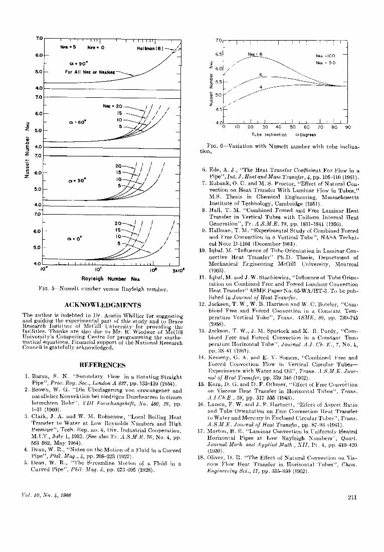
The present mathematical analysis, unfortunately does not lend itself to higher values of Rayleigh number and it appears that there is a need for some other method for complete mathematical solution of the problem. Since the present theory does not extend to higher values of Rayleigh numbers, the comparison of the experimented results th'~t include entrance effects is not possible. I t appears from Fig. 6 that for fixed values of the dimensionless parameters, the maximum value of heat transfer rate will be obtained between 20 deg and 60 deg of tube inclination. This interesting rcsult is somewhat similar to that of Larsen and Hart- nett 's ~6 who reportcd that in case of purc free convec- tion in a tube enclosed at both ends, maximum Nusselt number is obtained at about 30 (leg tube inclination.
210 Solar Energy
7.0
6 . 0
5 . 0
4 . 0
7 .0
6 . 0
Z 5.0
. Q
E 4 .0
z 7.0
s . o z
5 .0
I I ~1 i [ l i t i i I I i i l l ! i i ,,
- N I l " 5 N i l - 0 Hal lman [ 8 ] - . ~ , , ~
- ~ • 9 0 ° ~ - -
For All NRE or N R A N R I ¢ ~
- N ~ = 2 0 ~ / / / / -
, s - . ~ / ' / .i i ,, - " - - e L / / _ i
_ ~ = 6 0 o i v ~ i /
- 2 o - - ~ / / / / - tS- -~ / / / // / /
- 0 - 3 0 " I O ~ / / /
4 . 0
z o
6 .0
5 .0
4 .0 i 0 °
2 0 - - . . / / / / , . s - ~ t i / / / -
• O* 5 " " " ~ ' / ~ . / " . / -
I I I I llllI I I [ I I I I I ] I
I 0 ' IO = 3 x l O =
R 0 y l e i g h N u m b e r N a a
Fro . 5 Nusse l t n u m b e r versus t { a y l e i g h n u m b e r .
A C K N O W L E D G M E N T S
The au thor is indebted to l)r . Aus t in Whil l ier for suggest ing and guiding the exper imenta l par t ef this s t udy and to Brace Research Ins t i t u t e of McGill Un ive r s i ty for providing the facilities. T h a n k s are also due to Mr. R. Wiedwer of McGill Un ive r s i ty ' s Comput ing Centre for programming the mathe- mat ical equat ions. Financia l suppor t of the Na t iona l Research Council is grateful ly acknowledged.
R E F E R E N C E S
1. Barua , S. N. "Secondary Flow in a Ro ta t ing S t ra igh t P ipe" , Proc. Roy. Soc., London A 227, pp. 133-139 (1954).
2. Brown, W. G. "Die Uber lagerung yon erzwungener and na tu l i cher Konvek t ion bei niedrigen Durchsa tzen in e inum lo t rech ten R o h r " , VDI Forschungsheft, No. 480, 26, pp. 1-31 (1960).
3. Clark, J. A. and W. M. Rohsenow, "Local Boiling Hea t Transfer to Wate r at Low Reynolds Numbers and High Pressure" , Tech. Rep. no. 4, ])iv. Indus t r ia l Cooperat ion, M.I .T. , Ju ly 1, 1952. (See also Tr. A.S.M.E. 76, No. 4, pp. 553-562, May 1964).
4. Dean, W. R., "Notes on the Mot ion of a Fluid in a Curved P ipe" , Phil. Mag., 4, pp. 208-223 (1927).
5. Dean, W. R., "The Streamline Mot ion of a Fluid in a Curved P ipe" , Phil. Mag. 5, pp. 673-695 (1928).
7.0
6.5
6.o
~ 5.5 Z
~ 5.0
z
4.5
' I ' I ' I T I ~ I ~ 1 ~ [ ' I
N ~ E = 8 NRA =100
- / ~ NP. : 5 0 _ / . /
-/ (5
/ 4
i
4o J i I i I I i i I , I r I i I 0 i0 20 30 40 50 60 70 80
Tube Inclinotion cx Degrees
I
I 9o
Fro. 6 - -Var ia t ion wi th Nusse l t number wi th tube inclina- t ion.
6. Ede, A. J. , "The Hea t Transfer Coefficient For Flow in a P ipe" , Int. J. Heat and Mass Transfer, 4, PP. 105-110 (1961).
7. Eubank , O. C. and M. S. Proctor , "Effect of Na tu r a l Con- vect ion on Hea t Transfer Wi th Laminar Flow in Tubes , " M.S. Thesis in Chemical Engineering, Massachuse t t s In s t i t u t e of Technology, Cambridge (1951).
8. Hall , T. M. "Combined Forced and Free Laminar Hea t Transfer in Vert ical Tubes wi th Uniform In te rnM Hea t Genera t ion" , Tr. A.S.M.E. 78, pp. 1831-1841 (1956).
9. Hal lman, T. M. "Exper imen ta l S tudy of Combined Forced and Free Convect ion in a Vert ical Tube" , NASA Techni- cal No te D-1104 (1)ecember 1961).
10. Iqbal. M. "Inf luence of Tube Or ien ta t ion in Laminar Con- nect ive Hea t T rans fe r " Ph.D. Thesis, D e p a r t m e n t of Mechanical Engineer ing McGill Univers i ty , Mont rea l (1965).
11. Iqbal , M. and J. W. Stachiewicz, "Influence of Tube Orien- ta t ion on Combined Free and Forced Laminar Convect ion Hea t Trans fe r" ASME Paper No. 65-WA/HT-3. To be pub- lished in Journal of Heat Transfer.
12. Jackson, T. W., W. B. Harr ison and W. C. Boteler, "Com- bined Free and Forced Convect ion in a Cons tan t Tem- pera ture Vertical T u b e " , Trans. ASME, 80, pp. 739-745 (1958).
13. Jackson, T. W., J. M. Spurlock and K. R. Purdy, "Coin- bined Free and Forced Convect ion in a Cons tan t Tem- pera ture Horizontal Tube" , .lournal A.I. Ch.E., 7, No. 1, pp. 38-41 (1961).
14. Kemeny, G. A. and E. V. Somers, "Combined Free and Forced Convect ion Flow ill Vertical Circular T u b e s - - Exper iments wi th Water and Oil", Trans. A.S.M.E. Jour- nal of Heat Transfer, pp. 339-346 (1962).
15. Kern, D. G. and D. F. Othmer , "Effect. of Free Convect ion on Viscous Hea t Transfer in Horizonta l Tubes" , Trans. A.I.Ch.E., 39, pp. 517-555 (1943).
16. Larsen, F. W. and J. P. H a r t n e t t , "Efl'ect of Aspect Rat io and Tube Or ien ta t ion on Free Convect ion Hea t Transfer to Water and Mercury in Enclosed Circular Tubes" , Trans. A.S.M.E. Journal of Heat Transfer, pp. 87-93 (1961).
17. Mor ton , B. R. " L a m i n a r Convect ion in Uniformly Hea ted Hor izonta l Pipes at Low Rayleigh Number s " , Quart. Jo~ernal Mech. and Applied Math., XII , Pt . 4, pp. 410-420 (1959).
18. Oliver, I) . R. "The Effect of Na tu ra l Convect ion on Vis- cous Fh)w Hea t Transfer in Hor izonta l Tubes" , Chem. Engineering Sci., 17, pp. 335-350 (1962).
Vol. I0, No. 4, 1966 211