Embed Size (px)
Citation preview
1. INTRODUCTION
In recent decades, commercial malls became not only a
place where to shop but also a place where to relax and to
socialize. People spend a lot of their spare time in shopping
mall and new shopping centers are rising all over the city.
The reduction of energy consumptions in existing
commercial buildings and the identification of guidelines to
support the design of the future shopping centers is becoming
a pressing focus. Moreover, the Energy Performance of
Buildings Directive requires all new buildings to be nearly
zero-energy by the end of 2020 and all new public buildings
to be nearly zero-energy by 2018.
From 2006 to 2014, D’Agostino et al. [1] collected in the
framework of the Green Building Programme several data
about both new and existing non-residential buildings. They
found that non-residential buildings account on average for
25% energy consumption of the total European building
stock [2] and represent a heterogeneous sector compared with
the residential [3].
In particular, based on a study of the Buildings
Performance Institute Europe [4], among European non-
residential buildings it can be identify three categories:
wholesale & retail (28%), offices (23%), educational (17%),
hotels and restaurants (11%), hospitals (7%), sport facilities
(4%), other (11%) [1].
This sector holds a big percentage of total European final
energy consumption, especially in relation to commercial and
hospitals buildings [5]. The authors are involved in the
CommONEnergy project [6], funded by the European
Community Seventh Framework Programme, which has the
objective to develop a systematic approach to reduce energy
consumptions in shopping malls.
The data collection about non-residential buildings was
managed by the Joint Research Centre of the European
Commission and it has been operational in European
Member States as well as European Economic Area countries
[7].
Energy consumptions in shopping malls are primarily
based on guaranteeing a comfortable environment for
customers and heating, cooling and ventilation systems are
one of the main causes of energy use in shopping centers. [8].
Energy savings can be obtained by means of the adoption
of different efficient technological measures and several
among these concerns the HVAC system.
In particular, a feature of commercial mall is that, in order
to preserve the thermal comfort conditions, it could happen
some zones have to be cooled also during the middle and the
winter seasons. In fact, cooling requirement must balance
internal gains due to occupancy, lighting, electrical devices,
INTERNATIONAL JOURNAL OF HEAT AND TECHNOLOGY
ISSN: 0392-8764
Vol. 35, No. 4, December 2017, pp. 853-862
DOI: 10.18280/ijht.350422
Licensed under CC BY-NC 4.0
A publication of IIETA
http://www.iieta.org/Journals/IJHT
Free-cooling potential in shopping mall buildings with plants equipped by
dry-coolers boosted with evaporative pads
Alessandra De Angelis, Damiana Chinese, Onorio Saro
Department Polytechnic of Engineering and Architecture, via delle Scienze, 208, University of
Udine, Udine 33100, Italy
Email: [email protected]
ABSTRACT
Shopping malls are often characterized by high internal thermal loads due to occupancy, lighting, electrical
devices, and solar radiation entering through the large skylights. The aim of this study is the evaluation of the
energy saving reachable adding a cooling evaporative pad upstream a dry cooler. In particular, two different
cooling plant configurations has been investigated: a cooling plant with a chiller equipped with a dry cooler
(C-DC), that can be used as condenser of refrigeration system or to work with free-cooling mode and the
previous system equipped with an evaporative cooling pad upstream the dry cooler (C-E-DC) in order to
enlarge the range of temperatures suitable for free cooling. A building model of a typical shopping mall and
two cooling plant has been modeled by means of TRNSYS simulations carried out in several European cities.
Simulation results show that the C-E-DC configuration allows a greater energy saving amount than C-DC
configuration for all the cities considered. It can be noted that the locations with a hot or moderate climate
have a higher reduction in chiller electrical consumptions. Further investigations will be carried out taking in
to account more extensively the moisture content of the air for the different locations considered.
Keywords: Evaporative Pad, Energy Saving, Free Cooling, TRNSYS, Shopping Mall.
853
and solar radiation entering through the large skylights.
A typical cooling plant system in commercial buildings
consists of fan coil units fed with water coming from an air
conditioning system based on mechanical vapor compression.
This air conditioning system needs a significant amount of
electricity. The most widely used refrigeration plant for these
buildings is a water-cooled condensers system, that uses
recirculation water from cooling towers. In these systems,
water leaves the water-cooled condenser and enters the top of
the cooling tower, where it is sprayed over the fills and
cooled to a lower temperature by means of evaporation.
Thereafter it is supplied to the water-cooled condenser again.
A different cooling plant configuration contemplates
coupling a vapour compression chiller with a forced dry-
cooler condenser.
A significant advantage in realizing the condensing
process by means dry coolers is that, when the weather
conditions are suitable, water cooled by dry-coolers can be
directly supplied to fan-coils, without using the chiller and
achieving a free-cooling.
In a previous study [9] authors evaluated the feasibility and
the advantages to substitute cooling towers for dry-coolers.
For different locations, TRNSYS simulations were carried
out and the results shown that, in cities with a colder climate,
there is a greater energy saving due to a lower value of the
external mean air temperature; in particular, the city with the
greatest annual energy saving amount (42.4%) is Hamburg,
whereas the city with the lowest annual energy saving
amount (14.2%) is Messina.
It is important to find a strategy more efficient in hot
climates, where the periods suitable for free-cooling are
shorter.
In that climates, a way to improve the overall performance
of a cooling system and to reduce energy consumptions could
be the realization of an evaporative cooling process.
In fact, in a previous work [10] about the ability of
different plant configurations to improve indoor thermal
conditions in industrial building, the same authors found that,
the mechanical ventilation system allow an amount of energy
saving, in cold cities (Prague, Hamburg) about equal to 50%,
and in hot cities lower than 10%, whereas the direct and
indirect evaporative cooling systems allow an energy saving
around 50% and 40% for all considered locations
respectively.
With reference to the evaporative cooling pad, an analysis
of several studies from the literature highlighted that in most
cases the studies are experimental investigations about the
influence of several parameters on the evaporative pad
performance. Sohani et al. [11] proposed three model, i.e.
artificial network, genetic programming and multiple linear
regression to predict the overall performances of an
evaporative cellulose pad.
Malli et al. [12] tested in a sub sonic wind tunnel two
samples of cellulosic pad and found that effectiveness and
humidity variation decrease by increasing inlet air velocity.
Moreover, there are a lot of studies, which has been carried
out about the improvement of a cooling plant performance as
results of the insertion of an evaporative cooling pad.
An experimental study [13] has carried out in order to
investigate the impact of different cooling pads on the
performance of an air-conditioning system in Spain; the
authors found that the compression power consumption is
reduced by 11.4%, the cooling capacity is increased by 1.8%
and the overall COP is increased by 10.6%.
Wang et al. [14] carried out an experimental investigation
of the COP’s increase of an air conditioning plant equipped
with an evaporative cooling condenser; the authors evaluated
in addition to others parameters a power reduction up to 14.3%
on the compressor.
Islam et al. [15] analyzed experimentally and numerically
the performance of an air-conditioning unit equipped with an
evaporative-cooled condenser unit and found that, thanks to
the insertion of the latter, the coefficient of performance
(COP) of the plant increases by about 28%.
The effect of different cooling pads on the overall
performance of an air conditioning system is experimentally
evaluated by Martinez et al. [16] with the aim to identify the
thickness of the pad that maximize the COP of the system; it
is found an optimal thickness of 100 mm, which allows an
about 10.6% of COP increasing.
In a review paper Vakiloroaya et al. [17] studied the ability
of different approaches to increase the efficiency of HVAC
systems in order to obtain an HVAC energy saving. They
proposed a hybrid evaporative cooling system in order to
reduce the temperature of the outside air and compared the
results with measured data of an existing central cooling plan
of a commercial building: the proposed system allows an
energy saving potential up to 52% [18].
Other authors [19] combined a central cooling plant with a
regenerative evaporative cooling system and they evaluated
an electrical energy saving amount about 15.7 %.
A combined experimental plant consisting of an IEC unit
and a packaged unit air conditioner was realized and tested
by Delfani et al. [20]; they found a reduction in cooling load
up to 75% and a reduction in electrical energy consumption
around 55% during cooling season.
Previous studies [21], carried out by the same authors,
have evaluated the possible energy savings achievable by
means of dry coolers adoption in heating and cooling plants
serving office buildings.
In this work the aim is an evaluation of the energy saving
reachable in a shopping mall when an evaporative cooling
equipment is integrated with a dry cooler. The behavior of
that cooling plant is simulated by means of TRNSYS
simulations comparing the results, in terms of electrical
energy saving, with those of a cooling plant without the
evaporative pad.
A typical shopping mall has been modeled and several
locations corresponding to northern, central and southern
European cities has been considered.
2. REFERENCE BUILDING MODEL
Starting from a survey of the existing shopping malls in
the main European cities, a building model has been
identified.
The building is a rectangular double floor building with a
gross floor area of 20000m2 and a height of 4m. The total
volume is 160000m3. A shed roof with 12 vertical skylights,
0.70 x 2.5m, has been chosen. The longer edge of building is
oriented along north-south axis and the entrance glass doors
are on two shorter edges.
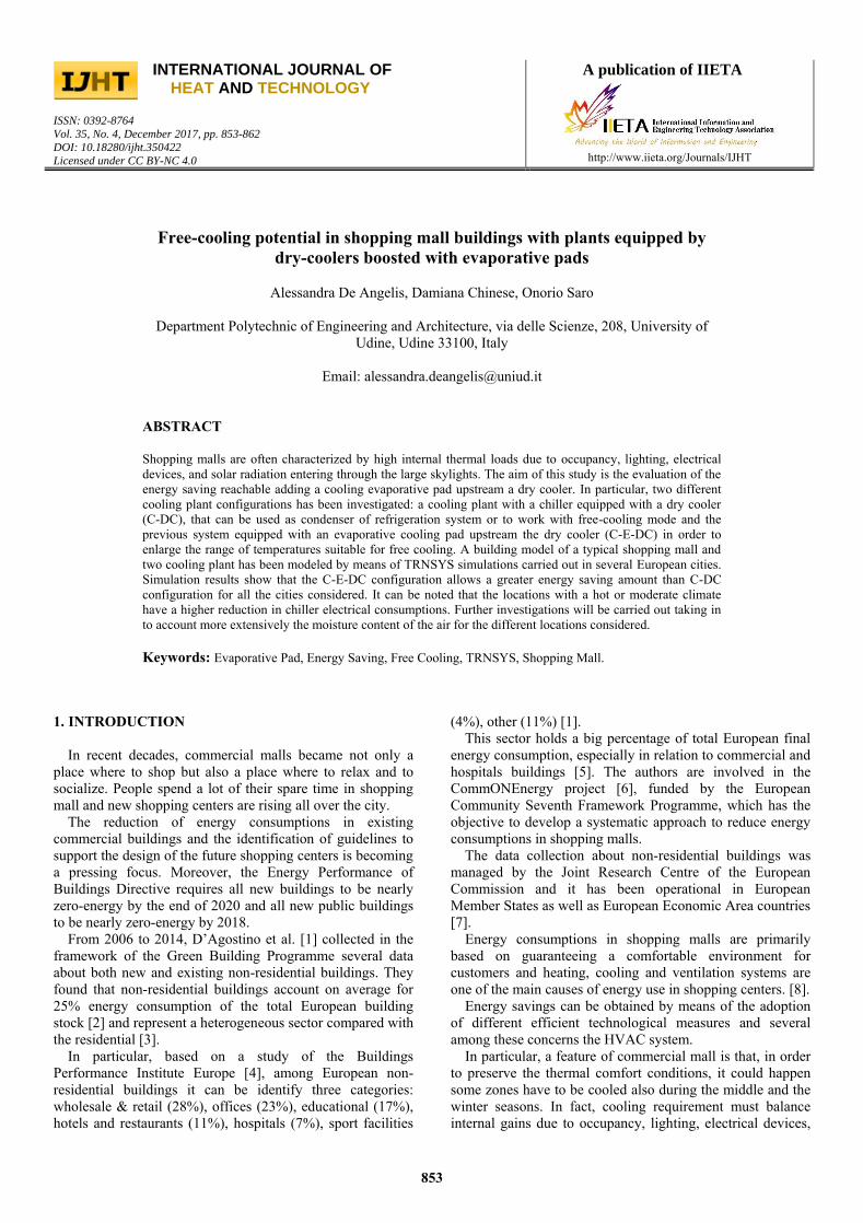
The internal layout of each floor is shown in Fig. 1-a,
where it can see that shops take up perimeter and core zones
and occupy 60% of the total floor area, leaving 40% of the
floor area to a common zone in order to allow a suitable
space for the flow of people during the peak time.
854
In order to take into account there are zones which
different expositions and because the relevant dimension of
building, different thermal zones, with the same internal load
and the same heat losses through wall, were set. In Fig. 1
different zones are summarized and are identified by means a
number.
Figure 1. Floor plan for the simulated building with using
destination and thermal zones
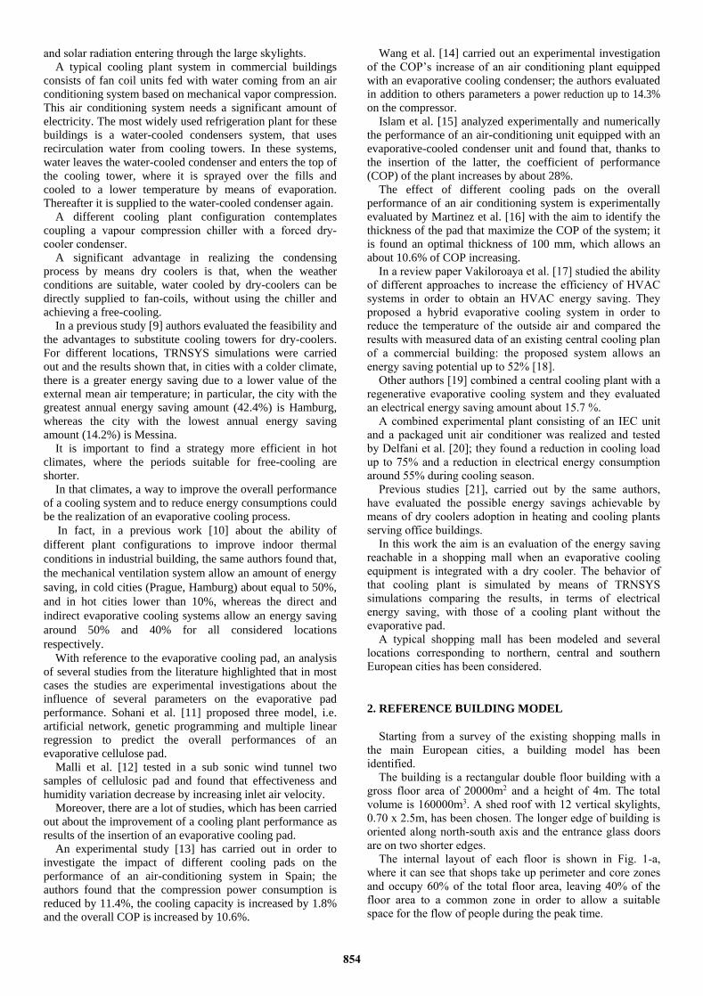
The model of the building, shown in Figure 2, was created
with TRNBuild module.
Figure 2. Sketch of the simulated commercial mall
The building elements properties were summarized in
Table 1.
Table 1. Building elements construction details
Element U [ W/m2K]
Exterior wall 0.351
Inner wall 0.456
Ground floor 0.340
Roof 0.283
Window 5.8
The amount of electrical equipment loads according to
ASHRAE Standard guidelines was set at 30W/m2 and was
split in a radiative part (30%) and a convective part (70%).
Thermal load of electrical equipment was calculated as
product of electrical power, interval time and a coefficient
depending on the day of the week; the coefficient was set to 1
during opening hours and to 0.2 during closing hours in order
to account for stand-by conditions.
Inside common zones, where there are skylights, windows
or entrance doors, an infiltration rate equal to 0.5 ACH (Air
Changes per Hour) was set.
Sensible and latent heat loads from people depend on their
activity and, according to ISO7730, assuming a light activity
for shopping mall, a load of 185W for each person (90
sensible and 95 latent) has been considered.
With regard to the number of people inside shopping mall,
based on UNI10339-2014, a design value of crowding index
equal to 0,2 person/m2 both sale zone and common zone has
been chosen. That value was scaled down depending on daily
and weekly schedule of occupant’s presence.
3. COOLING PLANT SYSTEMS
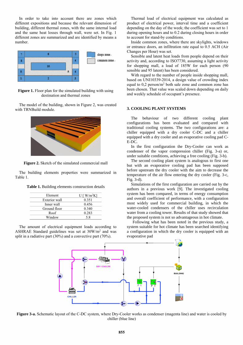
The behaviour of two different cooling plant
configurations has been evaluated and compared with
traditional cooling systems. The two configurations are: a
chiller equipped with a dry cooler C-DC and a chiller
equipped with a dry cooler and an evaporative cooling pad C-
E-DC.
In the first configuration the Dry-Cooler can work as
condenser of the vapor compression chiller (Fig. 3-a) or,
under suitable conditions, achieving a free cooling (Fig. 3-b).
The second cooling plant system is analogous to first one
but with an evaporative cooling pad has been supposed
before upstream the dry cooler with the aim to decrease the
temperature of the air flow entering the dry cooler (Fig. 3-c,
Fig. 3-d).
Simulations of the first configuration are carried out by the
authors in a previous work [9]. The investigated cooling
system has been compared, in terms of energy consumption
and overall coefficient of performance, with a configuration
most widely used for commercial building, in which the
water-cooled condensers of the chiller uses recirculation
water from a cooling tower. Results of that study showed that
the proposed system is not so advantageous in hot climate.
Following what has been noted in the previous study, a
system suitable for hot climate has been searched identifying
a configuration in which the dry cooler is equipped with an
evaporative pad
Figure 3-a. Schematic layout of the C-DC system, where Dry-Cooler works as condenser (magenta line) and water is cooled by
chiller (blue line)
DRY COOLER
BUILDING
CHILLER
855
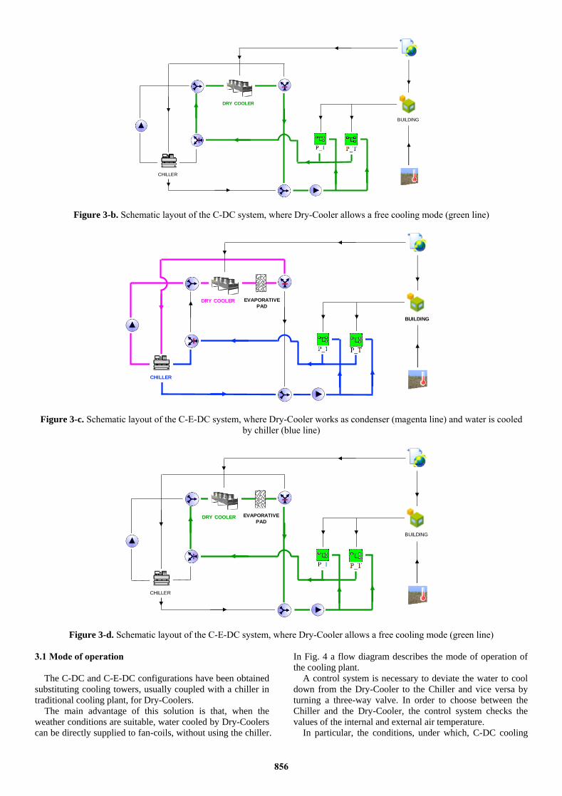
Figure 3-b. Schematic layout of the C-DC system, where Dry-Cooler allows a free cooling mode (green line)
Figure 3-c. Schematic layout of the C-E-DC system, where Dry-Cooler works as condenser (magenta line) and water is cooled
by chiller (blue line)
Figure 3-d. Schematic layout of the C-E-DC system, where Dry-Cooler allows a free cooling mode (green line)
3.1 Mode of operation
The C-DC and C-E-DC configurations have been obtained
substituting cooling towers, usually coupled with a chiller in
traditional cooling plant, for Dry-Coolers.
The main advantage of this solution is that, when the
weather conditions are suitable, water cooled by Dry-Coolers
can be directly supplied to fan-coils, without using the chiller.
In Fig. 4 a flow diagram describes the mode of operation of
the cooling plant.
A control system is necessary to deviate the water to cool
down from the Dry-Cooler to the Chiller and vice versa by
turning a three-way valve. In order to choose between the
Chiller and the Dry-Cooler, the control system checks the
values of the internal and external air temperature.
In particular, the conditions, under which, C-DC cooling
DRY COOLER
CHILLER
BUILDING
DRY COOLER
BUILDING
CHILLER
EVAPORATIVE
PAD
DRY COOLER
CHILLER
BUILDING
EVAPORATIVE
PAD
856
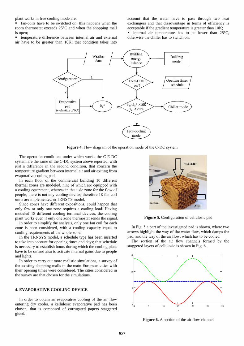
plant works in free cooling mode are:
▪ fan-coils have to be switched on: this happens when the
room thermostat exceeds 25°C and when the shopping mall
is open;
▪ temperature difference between internal air and external
air have to be greater than 10K; that condition takes into
account that the water have to pass through two heat
exchangers and that disadvantage in terms of efficiency is
acceptable if the gradient temperature is greater than 10K;
▪ internal air temperature has to be lower than 28°C,
otherwise the chiller has to switch on.
Figure 4. Flow diagram of the operation mode of the C-DC system
The operation conditions under which works the C-E-DC
system are the same of the C-DC system above reported, with
just a difference in the second condition, that concern the
temperature gradient between internal air and air exiting from
evaporative cooling pad.
In each floor of the commercial building 10 different
thermal zones are modeled, nine of which are equipped with
a cooling equipment, whereas in the aisle zone for the flow of
people, there is not any cooling device; therefore 18 fan coil
units are implemented in TRNSYS model.
Since zones have different expositions, could happen that
only few or only one zone requires a cooling load. Having
modeled 18 different cooling terminal devices, the cooling
plant works even if only one zone thermostat sends the signal.
In order to simplify the analysis, only one fan coil for each
zone is been considered, with a cooling capacity equal to
cooling requirements of the whole zone.
In the TRNSYS model, a schedule type has been inserted
to take into account for opening times and days; that schedule
is necessary to establish hours during which the cooling plant
have to be on and also to activate internal gains due to people
and lights.
In order to carry out more realistic simulations, a survey of
the existing shopping malls in the main European cities with
their opening times were considered. The cities considered in
the survey are that chosen for the simulations.
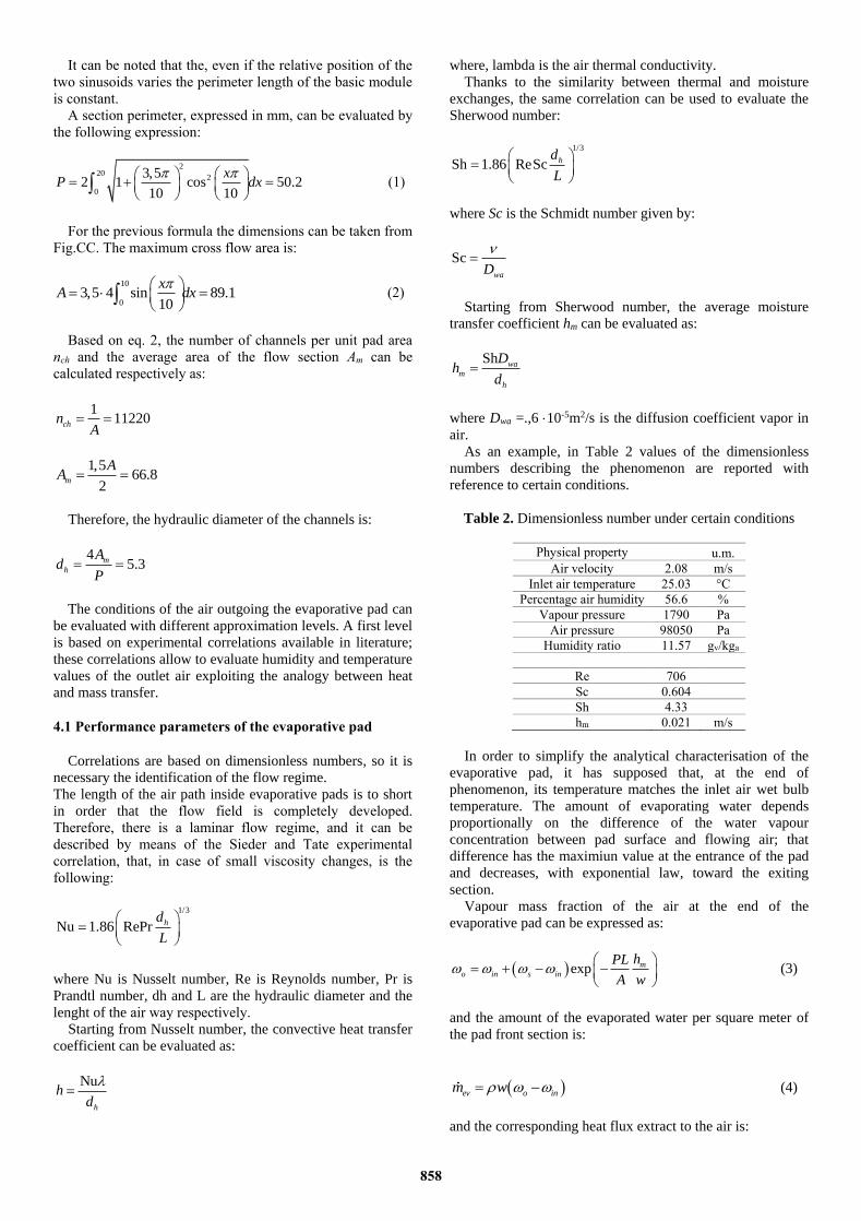
4. EVAPORATIVE COOLING DEVICE
In order to obtain an evaporative cooling of the air flow
entering dry cooler, a cellulosic evaporative pad has been
chosen, that is composed of corrugated papers staggered
glued.
Figure 5. Configuration of cellulosic pad
In Fig. 5 a part of the investigated pad is shown, where two
arrows highlight the way of the water flow, which damps the
pad, and the way of the air flow, which has to be cooled.
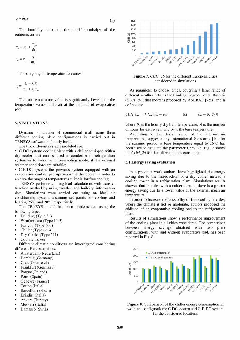
The section of the air flow channels formed by the
staggered layers of cellulosic is shown in Fig. 6.
Figure 6. A section of the air flow channel
857
It can be noted that the, even if the relative position of the
two sinusoids varies the perimeter length of the basic module
is constant.
A section perimeter, expressed in mm, can be evaluated by
the following expression:
2
202
0
3,52 1 cos 50.2
10 10
xP dx
(1)
For the previous formula the dimensions can be taken from
Fig.CC. The maximum cross flow area is:
10
03,5 4 sin 89.1
10
xA dx
(2)
Based on eq. 2, the number of channels per unit pad area
nch and the average area of the flow section Am can be
calculated respectively as:
111220chn
A
1,566.8
2m
AA
Therefore, the hydraulic diameter of the channels is:
45.3m
h
Ad
P
The conditions of the air outgoing the evaporative pad can
be evaluated with different approximation levels. A first level
is based on experimental correlations available in literature;
these correlations allow to evaluate humidity and temperature
values of the outlet air exploiting the analogy between heat
and mass transfer.
4.1 Performance parameters of the evaporative pad
Correlations are based on dimensionless numbers, so it is
necessary the identification of the flow regime.
The length of the air path inside evaporative pads is to short
in order that the flow field is completely developed.
Therefore, there is a laminar flow regime, and it can be
described by means of the Sieder and Tate experimental
correlation, that, in case of small viscosity changes, is the
following:
1/3
Nu 1.86 RePr hd
L
where Nu is Nusselt number, Re is Reynolds number, Pr is
Prandtl number, dh and L are the hydraulic diameter and the
lenght of the air way respectively.
Starting from Nusselt number, the convective heat transfer
coefficient can be evaluated as:
Nu
h
hd
where, lambda is the air thermal conductivity.
Thanks to the similarity between thermal and moisture
exchanges, the same correlation can be used to evaluate the
Sherwood number:
1/3
Sh 1.86 ReSc hd
L
where Sc is the Schmidt number given by:
ScwaD
Starting from Sherwood number, the average moisture
transfer coefficient hm can be evaluated as:
Sh wa
m
h
Dh
d
where Dwa =.,6 10-5m2/s is the diffusion coefficient vapor in
air.
As an example, in Table 2 values of the dimensionless
numbers describing the phenomenon are reported with
reference to certain conditions.
Table 2. Dimensionless number under certain conditions
Physical property u.m.
Air velocity 2.08 m/s
Inlet air temperature 25.03 °C
Percentage air humidity 56.6 %
Vapour pressure 1790 Pa
Air pressure 98050 Pa
Humidity ratio 11.57 gv/kga
Re 706
Sc 0.604
Sh 4.33
hm 0.021 m/s
In order to simplify the analytical characterisation of the
evaporative pad, it has supposed that, at the end of
phenomenon, its temperature matches the inlet air wet bulb
temperature. The amount of evaporating water depends
proportionally on the difference of the water vapour
concentration between pad surface and flowing air; that
difference has the maximiun value at the entrance of the pad
and decreases, with exponential law, toward the exiting
section.
Vapour mass fraction of the air at the end of the
evaporative pad can be expressed as:
exp m
o in s in
hPL
A w
(3)
and the amount of the evaporated water per square meter of
the pad front section is:
ev o inm w (4)
and the corresponding heat flux extract to the air is:
858
~ evq m r (5)
The humidity ratio and the specific enthalpy of the
outgoing air are:
ev
o in
a
mx x
m
o in
a
qe e
m
The outgoing air temperature becomes:
0
0
o o
o
pa pv
e x rt
c x c
That air temperature value is significantly lower than the
temperature value of the air at the entrance of evaporative
pad.
5. SIMULATIONS
Dynamic simulation of commercial mall using three
different cooling plant configurations is carried out in
TRNSYS software on hourly basis.
The two different systems modeled are:
▪ C-DC system: cooling plant with a chiller equipped with a
dry cooler, that can be used as condenser of refrigeration
system or to work with free-cooling mode, if the external
weather conditions are suitable;
▪ C-E-DC system: the previous system equipped with an
evaporative cooling pad upstream the dry cooler in order to
enlarge the range of temperatures suitable for free cooling.
TRNSYS performs cooling load calculations with transfer
function method by using weather and building information
data. Simulations were carried out using an ideal air
conditioning system, assuming set points for cooling and
heating 26°C and 20°C respectively.
The TRNSYS model has been implemented using the
following type:
▪ Building (Type 56)
▪ Weather data (Type 15-3)
▪ Fan coil (Type 600)
▪ Chiller (Type 666)
▪ Dry Cooler (Type 511)
▪ Cooling Tower
Different climatic conditions are investigated considering
different European cities:
▪ Amsterdam (Nederland)
▪ Hambug (Germany)
▪ Graz (Osterreich)
▪ Frankfurt (Germany)
▪ Prague (Poland)
▪ Porto (Spain)
▪ Genevre (France)
▪ Torino (Italia)
▪ Barcellona (Spain)
▪ Brindisi (Italia)
▪ Ankara (Turkey)
▪ Messina (Italia)
▪ Damasco (Syria)
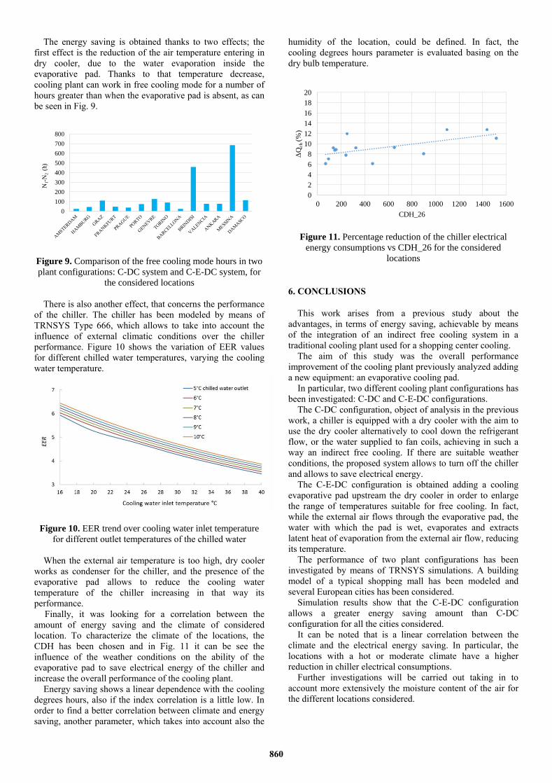
Figure 7. CDH_26 for the different European cities
considered in simulations
As parameter to choose cities, covering a large range of
different weather data, is the Cooling Degree-Hours, Base 0
(CDH_0); that index is proposed by ASHRAE [9bis] and is
defined as:
𝐶𝐷𝐻_𝜗0 = ∑ (𝜗𝑒 − 𝜗0)𝑁𝑗=1 for 𝜗𝑒 − 𝜗0 > 0
where e is the hourly dry bulb temperature, N is the number
of hours for entire year and 0 is the base temperature.
According to the design value of the internal air
temperature, suggested by International Standards [10] for
the summer period, a base temperature equal to 26°C has
been used to evaluate the parameter CDH_26. Fig. 7 shows
the CDH_26 for the different cities considered.
5.1 Energy saving evaluation
In a previous work authors have highlighted the energy
saving due to the introduction of a dry cooler instead a
cooling tower in a refrigeration plant. Simulations results
showed that in cities with a colder climate, there is a greater
energy saving due to a lower value of the external mean air
temperature.
In order to increase the possibility of free cooling in cities,
where the climate is hot or moderate, authors proposed the
addition of an evaporative cooling pad to the refrigeration
plant.
Results of simulations show a performance improvement
of the cooling plant in all cities considered. The comparison
between energy savings obtained with two plant
configurations, with and without evaporative pad, has been
reported in Fig. 8.
Figure 8. Comparison of the chiller energy consumption in
two plant configurations: C-DC system and C-E-DC system,
for the considered locations
0
200
400
600
800
1000
1200
1400
1600
CD
H_
26
0
500
1000
1500
2000
2500
Qch
(M
Wh)
C-DC configuration
C-E-DC configuration
859
The energy saving is obtained thanks to two effects; the
first effect is the reduction of the air temperature entering in
dry cooler, due to the water evaporation inside the
evaporative pad. Thanks to that temperature decrease,
cooling plant can work in free cooling mode for a number of
hours greater than when the evaporative pad is absent, as can
be seen in Fig. 9.
Figure 9. Comparison of the free cooling mode hours in two
plant configurations: C-DC system and C-E-DC system, for
the considered locations
There is also another effect, that concerns the performance
of the chiller. The chiller has been modeled by means of
TRNSYS Type 666, which allows to take into account the
influence of external climatic conditions over the chiller
performance. Figure 10 shows the variation of EER values
for different chilled water temperatures, varying the cooling
water temperature.
Figure 10. EER trend over cooling water inlet temperature
for different outlet temperatures of the chilled water
When the external air temperature is too high, dry cooler
works as condenser for the chiller, and the presence of the
evaporative pad allows to reduce the cooling water
temperature of the chiller increasing in that way its
performance.
Finally, it was looking for a correlation between the
amount of energy saving and the climate of considered
location. To characterize the climate of the locations, the
CDH has been chosen and in Fig. 11 it can be see the
influence of the weather conditions on the ability of the
evaporative pad to save electrical energy of the chiller and
increase the overall performance of the cooling plant.
Energy saving shows a linear dependence with the cooling
degrees hours, also if the index correlation is a little low. In
order to find a better correlation between climate and energy
saving, another parameter, which takes into account also the
humidity of the location, could be defined. In fact, the
cooling degrees hours parameter is evaluated basing on the
dry bulb temperature.
Figure 11. Percentage reduction of the chiller electrical
energy consumptions vs CDH_26 for the considered
locations
6. CONCLUSIONS
This work arises from a previous study about the
advantages, in terms of energy saving, achievable by means
of the integration of an indirect free cooling system in a
traditional cooling plant used for a shopping center cooling.
The aim of this study was the overall performance
improvement of the cooling plant previously analyzed adding
a new equipment: an evaporative cooling pad.
In particular, two different cooling plant configurations has
been investigated: C-DC and C-E-DC configurations.
The C-DC configuration, object of analysis in the previous
work, a chiller is equipped with a dry cooler with the aim to
use the dry cooler alternatively to cool down the refrigerant
flow, or the water supplied to fan coils, achieving in such a
way an indirect free cooling. If there are suitable weather
conditions, the proposed system allows to turn off the chiller
and allows to save electrical energy.
The C-E-DC configuration is obtained adding a cooling
evaporative pad upstream the dry cooler in order to enlarge
the range of temperatures suitable for free cooling. In fact,
while the external air flows through the evaporative pad, the
water with which the pad is wet, evaporates and extracts
latent heat of evaporation from the external air flow, reducing
its temperature.
The performance of two plant configurations has been
investigated by means of TRNSYS simulations. A building
model of a typical shopping mall has been modeled and
several European cities has been considered.
Simulation results show that the C-E-DC configuration
allows a greater energy saving amount than C-DC
configuration for all the cities considered.
It can be noted that is a linear correlation between the
climate and the electrical energy saving. In particular, the
locations with a hot or moderate climate have a higher
reduction in chiller electrical consumptions.
Further investigations will be carried out taking in to
account more extensively the moisture content of the air for
the different locations considered.
0
100
200
300
400
500
600
700
800
N1-N
2(h
)
0
2
4
6
8
10
12
14
16
18
20
0 200 400 600 800 1000 1200 1400 1600
ΔQ
ch
(%
)
CDH_26
860
RFERENCES
[1] D'Agostino D., Cuniberti B., Bertoldi P. (2017).
Energy consumption and efficiency technology
measures in European non-residential buildings,
Energy and Buildings, Vol. 153, pp. 72-86. DOI:
10.1016/j.enbuild.2017.07.062
[2] D'Agostino D., Zangheri P., Castellazzi L. (2017).
Towards Nearly Zero Energy Buildings (NZEBs) in
Europe: A focus on retrofit in non-residential
buildings, Energies, Vol 10, p. 117. DOI:
10.3390/en10010117
[3] D'Agostino D. (2015). Assessment of the progress
towards the establishment of definitions of Nearly
Zero Energy Buildings (NZEBs) in European Member
States, J. Build. Eng., DOI: 10.1016/j.jobe.2015
[4] Zebra 2020, Nearly zero energy building strategy
2020- Strategies for a nearly Zero-Energy Building
market transition in the European Union.
[5] BPIE Europe’s Buildings Under the Microscope
(2011).
[6] Cortella G., Lollini R., Noris F., D'Agaro P., Saro O.
(2014). CommONEnergy: Re‐conceptualizing
shopping malls from consumerism to energy
conservation, Refrigeration Science and Technology.
Science Et Technique Du Froid, Vol. 2014, pp. 582-
589.
[7] Valentová M., Bertoldi P. (2011). Evaluation of the
green building programme, Energy Build, Vol. 43, pp.
1875-1883.
[8] Bointner R., Toleikyte A., Woods R., Atanasiu B., De
Ferrari A., Farinea C., Noris F. (2013). Shopping malls
features in EU-28 + Norway, Deliverable 2.1 for
CommONEnergy FP7-2013-NMP-ENV-EeB.
[9] De Angelis A., Ceccotti L., Saro O. (2017). Energy
savings evaluation for dry-cooler equipped plants in
shopping mall buildings, International Journal of Heat
and Technology, Vol. 35, No. Special Issue 1, pp.
S361-S366. DOI: 10.18280/ijht.35Sp0149
[10] De Angelis A., Saro O., Truant M. (2017).
Evaporative cooling systems to improve internal
comfort in industrial buildings, Energy Procedia, Vol.
126, pp. 313-320. DOI: 10.1016/j.egypro.2017.08.245
[11] Sohani A., Zabihigivi M., Moradi M.H., Sayyaadi H.,
Balyani H.H. (2017). A comprehensive performance
investigation of cellulose evaporative cooling pad
systems using predictive approaches, Applied Thermal
Engineering, Vol. 110, pp. 1589-1608.
[12] Malli A., Seyf H.R., Layeghi M., Sharifian S.,
Behravesh H. (2011). Investigating the performance of
cellulosic evaporative cooling pads, Energy
Conversion and Management, Vol. 52, pp. 2598-2603.
[13] Martinez P., Ruiz J., Cutillas C.G., Martinez P.J.,
Kaiser A.S., Lucas M. (2016). Experimental study on
energy performance of a split air-conditioner by using
variable thickness evaporative cooling pads coupled to
the condenser, Applied Thermal Engineering, Vol. 105,
pp. 1041-1050.
[14] Wang T., Sheng C., Agwu Nnanna A.G. (2014).
Experimental investigation of air conditioning system
using evaporative cooling condenser, Energy and
Buildings, Vol. 81, pp. 435-443.
[15] Islam M.R., Jahangeer K.A., Chua K.J. (2015).
Experimental and numerical study of an evaporatively-
cooled condenser of air-conditioning systems, Energy,
Vol. 87, pp. 390-399.
[16] Martinez P., Ruiz J., Cutillas C.G., Martinez P.J.,
Kaiser A.S., Lucas M. (2016). Experimental study on
energy performance of a split air-conditioner by using
variable thickness evaporative cooling pads coupled to
the condenser, Applied Thermal Engineering, Vol. 105,
pp. 1041-1050.
[17] Vakiloroaya V., Samali B., Fakhar A., Pishghadam K.
(2014). A review of different strategies for HVAC
energy saving, Energy Conversion and Management,
Vol. 77, pp. 738-754. DOI:
10.1016/j.enconman.2013.10.023
[18] Vakiloroaya V., Khatibi M., Ha Q.P., Samali B.
(2011). New integrated hybrid evaporative cooling
system for HVAC energy efficiency improvement,
IEEE/SICE International Symposium on System
Integration, Kyoto, Japan, pp 591-596. DOI:
10.1109/SII.2011.6147546
[19] Khandelwal A., Talukdar P., Jain S. (2011). Energy
savings in a building using regenerative evaporative
cooling, Energy Build, Vol. 43, pp. 581-591. DOI:
10.1016/j.enbuild.2010.10.026
[20] Delfani S., Esmaeelian J., Pasdarshahri H., Karami M.
(2010). Energy saving potential of an indirect
evaporative cooler as a pre-cooling unit for
mechanical cooling systems in Iran, Energy and
Buildings, Vol. 42, pp 2169-2176. DOI:
10.1016/j.enbuild.2010.07.009
[21] De Angelis A., Ceccotti L., Saro O. (2016). Cooling
energy savings with dry-cooler equipped plants in
office buildings, International Journal of Heat and
Technology, Vol. 34, No. Special Issue 2, pp. S205-
S211. DOI: 10.18280/ijht.34S203
[22] De Angelis A., Ceccotti L., Saro O. (2016). Cooling
energy savings with dry-cooler equipped plants in
office buildings, International Journal of Heat and
Technology, Vol. 34, No. Special Issue 2, pp. S205-
S211. DOI: 10.18280/ijht.34S203
[23] De Angelis A., Medici M., Saro O., Lorenzini G. (2015).
Evaluation of evaporative cooling systems in industrial
buildings, International Journal of Heat and
Technology, Vol. 33, No. 3, pp. 1-10.
NOMENCLATURE
A area, m2
cp specific heat capacity, kJ/kgK
d diameter, m
e specific enthalpy, J/kg
h heat transfer coefficient, W/m2K
n number
N number of hours, h
P perimeter, m
Q electrical energy, Wh
Nu Nusselt number (dimensionless)
Pr Prandtl number (dimensionless)
Re Reynolds number (dimensionless)
Sc Schmidt number (dimensionless)
Sh Sherwood number (dimensionless)
x humidity ratio
U thermal transmittance, W/m2K
temperature
861
density, kg/m3
thermal conductivity, W/mK
kinematic viscosity, m2/s
Subscripts
a air
e external
w water
c chilled
ch chiller
ev evaporated
h hydraulic
o outlet
in inlet
862