Embed Size (px)
Citation preview
Thank you for choosing Commercial Air Conditioners, please read thisowner’s manual carefully before operation and retain it for future reference.
Commercial Air ConditionersOwner's Manual
Free Match Series R410A GMV Multi VRF Cassette Type Indoor Unit (For North America)

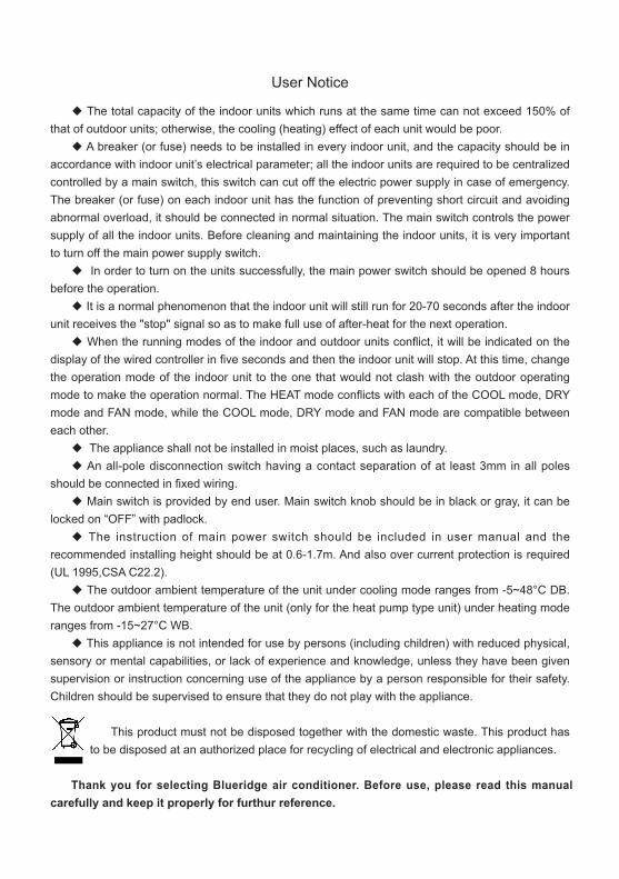
User Notice
◆ The total capacity of the indoor units which runs at the same time can not exceed 150% of that of outdoor units; otherwise, the cooling (heating) effect of each unit would be poor.
◆ A breaker (or fuse) needs to be installed in every indoor unit, and the capacity should be in accordance with indoor unit’s electrical parameter; all the indoor units are required to be centralized controlled by a main switch, this switch can cut off the electric power supply in case of emergency. The breaker (or fuse) on each indoor unit has the function of preventing short circuit and avoiding abnormal overload, it should be connected in normal situation. The main switch controls the power supply of all the indoor units. Before cleaning and maintaining the indoor units, it is very important to turn off the main power supply switch.
◆ In order to turn on the units successfully, the main power switch should be opened 8 hours before the operation.
◆ It is a normal phenomenon that the indoor unit will still run for 20-70 seconds after the indoor unit receives the "stop" signal so as to make full use of after-heat for the next operation.
◆ When the running modes of the indoor and outdoor units conflict, it will be indicated on the display of the wired controller in five seconds and then the indoor unit will stop. At this time, change the operation mode of the indoor unit to the one that would not clash with the outdoor operating mode to make the operation normal. The HEAT mode conflicts with each of the COOL mode, DRY mode and FAN mode, while the COOL mode, DRY mode and FAN mode are compatible between each other.
◆ The appliance shall not be installed in moist places, such as laundry.◆ An all-pole disconnection switch having a contact separation of at least 3mm in all poles
should be connected in fixed wiring.◆ Main switch is provided by end user. Main switch knob should be in black or gray, it can be
locked on “OFF” with padlock.◆ The instruction of main power switch should be included in user manual and the
recommended installing height should be at 0.6-1.7m. And also over current protection is required (UL 1995,CSA C22.2).
◆ The outdoor ambient temperature of the unit under cooling mode ranges from -5~48°C DB. The outdoor ambient temperature of the unit (only for the heat pump type unit) under heating mode ranges from -15~27°C WB.
◆ This appliance is not intended for use by persons (including children) with reduced physical, sensory or mental capabilities, or lack of experience and knowledge, unless they have been given supervision or instruction concerning use of the appliance by a person responsible for their safety.Children should be supervised to ensure that they do not play with the appliance.
This product must not be disposed together with the domestic waste. This product has to be disposed at an authorized place for recycling of electrical and electronic appliances.
Thank you for selecting Blueridge air conditioner. Before use, please read this manual carefully and keep it properly for furthur reference.
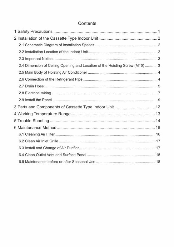
Contents
1 Safety Precautions .......................................................................................... 12 Installation of the Cassette Type Indoor Unit ................................................... 2
2.1 Schematic Diagram of Installation Spaces ............................................................ 2
2.2 Installation Location of the Indoor Unit ................................................................... 2
2.3 Important Notice: .................................................................................................... 3
2.4 Dimension of Ceiling Opening and Location of the Hoisting Screw (M10) ............ 3
2.5 Main Body of Hoisting Air Conditioner ................................................................... 4
2.6 Connection of the Refrigerant Pipe ........................................................................ 4
2.7 Drain Hose ............................................................................................................. 5
2.8 Electrical wiring ...................................................................................................... 7
2.9 Install the Panel ..................................................................................................... 9
3 Parts and Components of Cassette Type Indoor Unit ................................. 124 Working Temperature Range ......................................................................... 135 Trouble Shooting ........................................................................................... 146 Maintenance Method ..................................................................................... 16
6.1 Cleaning Air Filter ................................................................................................. 16
6.2 Clean Air Inlet Grille ............................................................................................. 17
6.3 Install and Change of Air Purifier ......................................................................... 17
6.4 Clean Outlet Vent and Surface Panel .................................................................. 18
6.5 Maintenance before or after Seasonal Use ......................................................... 18
Free Match for North America
1
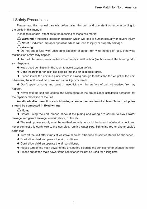
1 Safety PrecautionsPlease read this manual carefully before using this unit, and operate it correctly according to
the guide in this manual.Please take special attention to the meaning of these two marks:
Warning! It indicates improper operation which will lead to human casualty or severe injury. Note! It indicates improper operation which will lead to injury or property damage. Warning:
◆ Do not adopt fuse with unsuitable capacity or adopt iron wire instead of fuse, otherwise malfunction or fire may happen.
◆ Turn off the main power switch immediately if malfunction (such as smell the burning odor etc.) happens.
◆ Keep good ventilation in the room to avoid oxygen deficit.◆ Don’t insert finger or stick-like objects into the air inlet/outlet grille.◆ Please install the unit in a place where is strong enough to withstand the weight of the unit;
otherwise, the unit would fall down and cause injury or death.◆ Don’t apply or spray and paint or insecticide on the surface of unit, otherwise, fire may
happen.◆ Never refit the unit and contact the sales agent or the professional installation personnel for
the repair or relocation of the unit.An all-pole disconnection switch having a contact separation of at least 3mm in all poles
should be connected in fixed wiring.
Note:◆ Before using the unit, please check if the piping and wiring are correct to avoid water
leakage, refrigerant leakage, electric shock, or fire etc.◆ The main power supply must be earthed soundly to avoid the hazard of electric shock and
never connect this earth wire to the gas pipe, running water pipe, lightening rod or phone cable's earth lead.
◆ Turn off the unit after it runs at least five minutes; otherwise its service life will be shortened. ◆ Don’t allow children operate the air conditioner.◆ Don’t allow children operate the air conditioner.◆ Please turn off the main power of the unit before cleaning the conditioner or change the filter.◆ Please cut off the main power if the conditioner will not be used for a long time.
Free Match for North America
2
2 Installation of the Cassette Type Indoor Unit
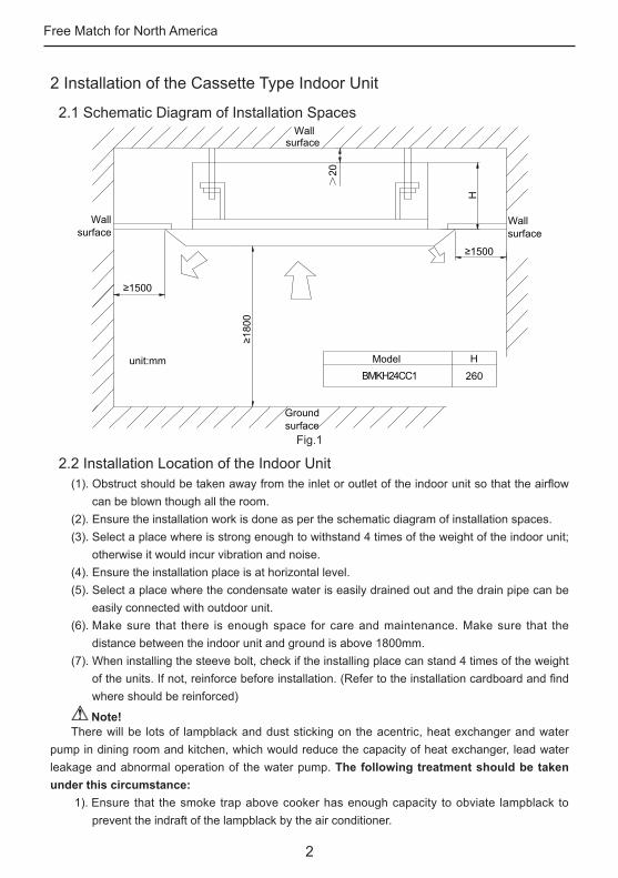
2.1 Schematic Diagram of Installation Spaces
BMKH24CC1Model H
260unit:mm
>20
Wall surface
Wall surface
Wallsurface
Ground surface
H
Fig.1
2.2 Installation Location of the Indoor Unit(1). Obstruct should be taken away from the inlet or outlet of the indoor unit so that the airflow
can be blown though all the room.(2). Ensure the installation work is done as per the schematic diagram of installation spaces.(3). Select a place where is strong enough to withstand 4 times of the weight of the indoor unit;
otherwise it would incur vibration and noise. (4). Ensure the installation place is at horizontal level. (5). Select a place where the condensate water is easily drained out and the drain pipe can be
easily connected with outdoor unit.(6). Make sure that there is enough space for care and maintenance. Make sure that the
distance between the indoor unit and ground is above 1800mm.(7). When installing the steeve bolt, check if the installing place can stand 4 times of the weight
of the units. If not, reinforce before installation. (Refer to the installation cardboard and find where should be reinforced)
Note!There will be lots of lampblack and dust sticking on the acentric, heat exchanger and water
pump in dining room and kitchen, which would reduce the capacity of heat exchanger, lead water leakage and abnormal operation of the water pump. The following treatment should be taken under this circumstance:
1). Ensure that the smoke trap above cooker has enough capacity to obviate lampblack to prevent the indraft of the lampblack by the air conditioner.
Free Match for North America
3
2). Keep the air conditioner far from the kitchen so that the lampblack would not be indraft by the air conditioner.
2.3 Important Notice:◆ To guarantee the good performance, the unit must be installed by technician according with
this instruction.◆ Please contact the local Blueridge special nominated repair department before installation. Any
malfunction caused by the unit that is installed by the department that is not special nominated by Blueridge would not deal without time by the inconvenience of the business contact.
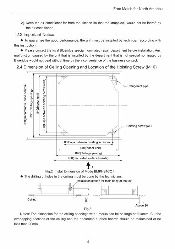
2.4 Dimension of Ceiling Opening and Location of the Hoisting Screw (M10)
A
Refrigerant pipe
780(
Gap
s be
twee
n ho
istin
g sc
rew
rods
)
840(
Indo
or u
nit)
890*
(Cei
ling
open
ing)
950(
Dec
orat
ed s
urfa
ce b
oard
s)
Hoisting screw (X4)
950(Decorated surface boards)
890(Ceiling opening)
840( Indoor unit)
680(Gaps between hoisting screw rods)
Fig.2 Install Dimension of Mode BMKH24CC1◆ The drilling of holes in the ceiling must be done by the technicians.
Ceiling
Installation stands for main body of the unit
(160
)
Above 20Fig.3
Notes: The dimension for the ceiling openings with * marks can be as large as 910mm. But the overlapping sections of the ceiling and the decorated surface boards should be maintained at no less than 20mm.
Free Match for North America
4
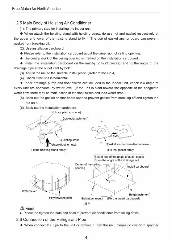
2.5 Main Body of Hoisting Air Conditioner(1). The primary step for installing the indoor unit.◆ When attach the hoisting stand with hoisting screw, do use nut and gasket respectively at
the upper and lower of the hoisting stand to fix it. The use of gasket anchor board can prevent gasket from breaking off.
(2). Use installation cardboard◆ Please refer to the installation cardboard about the dimension of ceiling opening.◆ The central mark of the ceiling opening is marked on the installation cardboard.◆ Install the installation cardboard on the unit by bolts (3 pieces), and fix the angle of the
drainage pipe at the outlet vent by bolt.(3). Adjust the unit to the suitable install place. (Refer to the Fig.4)(4). Check if the unit is horizontal.◆ Inner drainage pump and float switch are included in the indoor unit, check if 4 angle of
every unit are horizontal by water level. (If the unit is slant toward the opposite of the coagulate water flow, there may be malfunction of the float switch and lead water drop.)
(5). Back-out the gasket anchor board used to prevent gasket from breaking off and tighten the nut on it.
(6). Back-out the installation cardboard.Nut(supplied at scene)
Gasket(attachment)
Gasket anchor board(attachment)
Bolt of one of the angle of outlet pipe is fix on the angle of the drainage solt
Bolt(attachment)Bolt(attachment)
Water lever
Polyethylene pipe
Center of the ceiling opening
Insert
Install cardboard
Hoisting standTighten(double nuts)
[Fix the hoisting stand firmly] [Fix the gasket firmly]
[Fix the install cardboard]Fig.4
Note!● Please do tighten the nuts and bolts to prevent air conditioner from falling down.
2.6 Connection of the Refrigerant Pipe◆ When connect the pipe to the unit or remove it from the unit, please do use both spanner
Free Match for North America
5
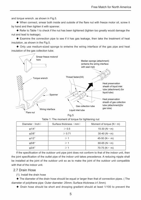
and torque wrench. as shown in Fig.5.◆ When connect, smear both inside and outside of the flare nut with freeze motor oil, screw it
by hand and then tighten it with spanner.◆ Refer to Table 1 to check if the nut has been tightened (tighten too greatly would damage the
nut and lead to leakage).◆ Examine the connection pipe to see if it has gas leakage, then take the treatment of heat
insulation, as shown in the Fig.5.◆ Only use medium-sized sponge to entwine the wiring interface of the gas pipe and heat
insulation of the gas collection tube.
Smear freeze motoroil here
Spanner
Thread fasten(X4)
Median sponge (attachment) (entwine the wiring interface with seal mat)
Gas collection tube
Liquid inlet tube
Heat preservation sheath of liquid inlet tube (attachment) (for liquid tube)
Heat preservation sheath of gas collection tube (attachment)(for gas tube)
Flare nutWiring interface
Torque wrench
Fig.5Table 1: The moment of torque for tightening nut
Diameter(Inch) Surface thickness(mm) Moment of torque (N·m)
φ1/4’’ ≥ 0.5 15-30 (N·m)
φ3/8’’ ≥ 0.71 30-40 (N·m)
φ1/2’’ ≥ 1 45-50 (N··m)
φ5/8’’ ≥ 1 60-65 (N·m)
φ3/4’’ ≥ 1 70-75 (N··m)
If the specification of the outdoor unit pipe joint does not conform to that of the indoor unit, then the joint specification of the outlet pipe of the indoor unit takes precedence. A reducing nipple shall be installed at the joint of the outdoor unit so as to make the joint of the outdoor unit compatible with that of the indoor unit.
2.7 Drain Hose(1). Install the drain hose◆ The diameter of the drain hose should be equal or larger than that of connection pipes. ( The
diameter of polythene pipe: Outer diameter: 25mm; Surface thickness ≥1.5mm) ◆ Drain hose should be short and drooping gradient should at least 1/100 to prevent the
Free Match for North America
6
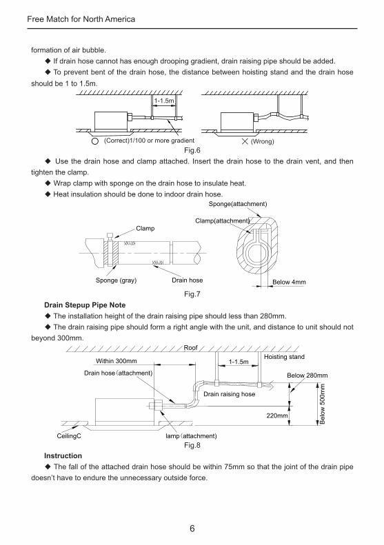
formation of air bubble.◆ If drain hose cannot has enough drooping gradient, drain raising pipe should be added. ◆ To prevent bent of the drain hose, the distance between hoisting stand and the drain hose
should be 1 to 1.5m.
1-1.5m
(Correct)1/100 or more gradient (Wrong)Fig.6
◆ Use the drain hose and clamp attached. Insert the drain hose to the drain vent, and then tighten the clamp.
◆ Wrap clamp with sponge on the drain hose to insulate heat.◆ Heat insulation should be done to indoor drain hose.
Sponge(attachment)
Clamp(attachment)
Below 4mm
Clamp
Drain hoseSponge (gray)
Fig.7Drain Stepup Pipe Note ◆ The installation height of the drain raising pipe should less than 280mm.◆ The drain raising pipe should form a right angle with the unit, and distance to unit should not
beyond 300mm.
Drain hose(attachment)
Within 300mm
Roof
Drain raising hose
220mm
1-1.5mHoisting stand
Below 280mm
Bel
ow 5
00m
m
CeilingC lamp(attachment)Fig.8
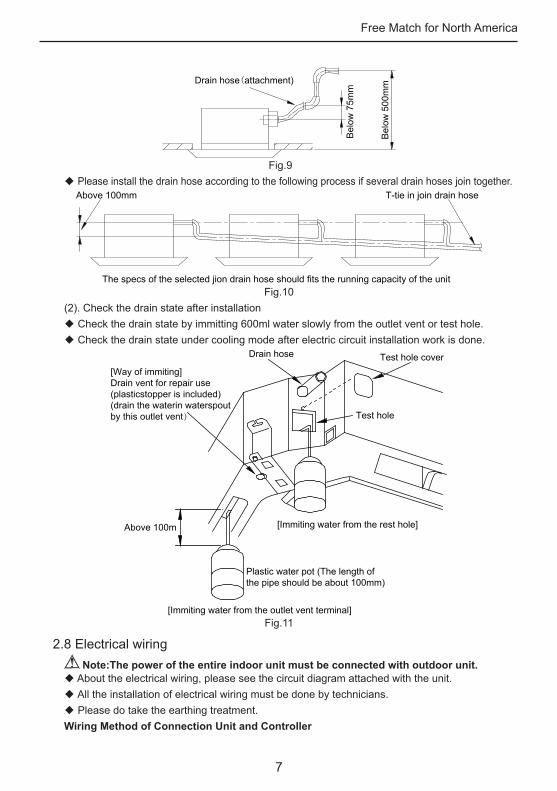
Instruction◆ The fall of the attached drain hose should be within 75mm so that the joint of the drain pipe
doesn’t have to endure the unnecessary outside force.
Free Match for North America
7
Drain hose(attachment)
Bel
ow 5
00m
m
Bel
ow 7
5mm
Fig.9◆ Please install the drain hose according to the following process if several drain hoses join together.
Above 100mm T-tie in join drain hose
The specs of the selected jion drain hose should fits the running capacity of the unitFig.10
(2). Check the drain state after installation◆ Check the drain state by immitting 600ml water slowly from the outlet vent or test hole.◆ Check the drain state under cooling mode after electric circuit installation work is done.
Above 100m
Drain hose Test hole cover
Test hole
[Immiting water from the rest hole]
[Immiting water from the outlet vent terminal]
Plastic water pot (The length of the pipe should be about 100mm)
[Way of immiting]Drain vent for repair use(plasticstopper is included)(drain the waterin waterspoutby this outlet vent)
Fig.11
2.8 Electrical wiring Note:The power of the entire indoor unit must be connected with outdoor unit.
◆ About the electrical wiring, please see the circuit diagram attached with the unit.◆ All the installation of electrical wiring must be done by technicians.◆ Please do take the earthing treatment.Wiring Method of Connection Unit and Controller
Free Match for North America
8
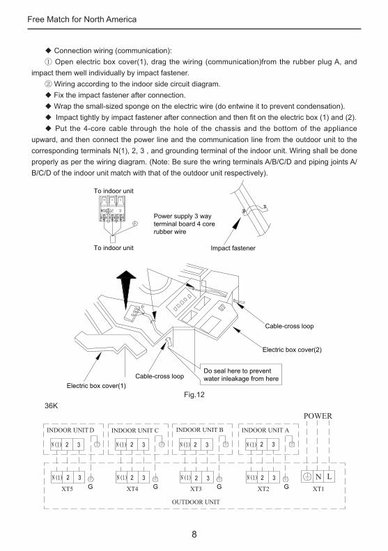
◆ Connection wiring (communication):① Open electric box cover(1), drag the wiring (communication)from the rubber plug A, and
impact them well individually by impact fastener.② Wiring according to the indoor side circuit diagram.◆ Fix the impact fastener after connection.◆ Wrap the small-sized sponge on the electric wire (do entwine it to prevent condensation).◆ Impact tightly by impact fastener after connection and then fit on the electric box (1) and (2).◆ Put the 4-core cable through the hole of the chassis and the bottom of the appliance
upward, and then connect the power line and the communication line from the outdoor unit to the corresponding terminals N(1), 2, 3 , and grounding terminal of the indoor unit. Wiring shall be done properly as per the wiring diagram. (Note: Be sure the wring terminals A/B/C/D and piping joints A/B/C/D of the indoor unit match with that of the outdoor unit respectively).
To indoor unit
To indoor unit Impact fastener
Electric box cover(1)Cable-cross loop
Cable-cross loop
Do seal here to preventwater inleakage from here
Electric box cover(2)
Power supply 3 wayterminal board 4 corerubber wire
Fig.1236K
POWER
INDOOR UNIT D INDOOR UNIT C INDOOR UNIT B INDOOR UNIT A
XT XT XT2
OUTDOOR UNIT
N L
Free Match for North America
9
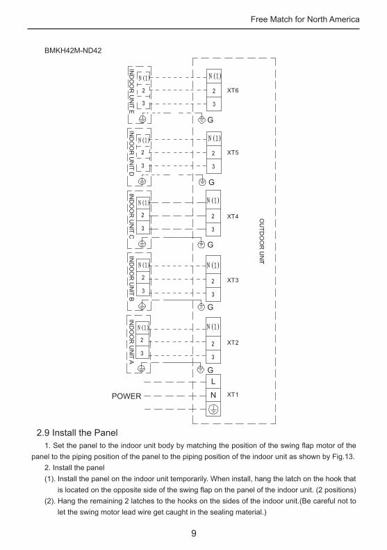
BMKH42M-ND42
POWER
IND
OO
R U
NIT A
IND
OO
R U
NIT B
IND
OO
R U
NIT C
IND
OO
R U
NIT D
OU
TDO
OR
UN
I T
IND
OO
R U
NIT E
XT2
XT1
XT3
XT4
XT5
XT6
N
L
G
G
G
G
G
2.9 Install the Panel1. Set the panel to the indoor unit body by matching the position of the swing flap motor of the
panel to the piping position of the panel to the piping position of the indoor unit as shown by Fig.13.2. Install the panel(1). Install the panel on the indoor unit temporarily. When install, hang the latch on the hook that
is located on the opposite side of the swing flap on the panel of the indoor unit. (2 positions)(2). Hang the remaining 2 latches to the hooks on the sides of the indoor unit.(Be careful not to
let the swing motor lead wire get caught in the sealing material.)
Free Match for North America
10
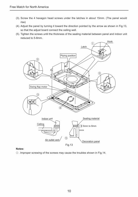
(3). Screw the 4 hexagon head screws under the latches in about 15mm. (The panel would rise)
(4). Adjust the panel by turning it toward the direction pointed by the arrow as shown in Fig.13, so that the adjust board connect the ceiling well.
(5). Tighten the screws until the thickness of the sealing material between panel and indoor unit reduced to 5-8mm.
Latch
Piping position
Swing flap motor
Indoor unit
Ceiling
Air outlet vent Decoration panel
5mm to 8mm
Sealing material
Hook
Fig.13Notes:① .Improper screwing of the screws may cause the troubles shown in Fig.14.
Free Match for North America
11
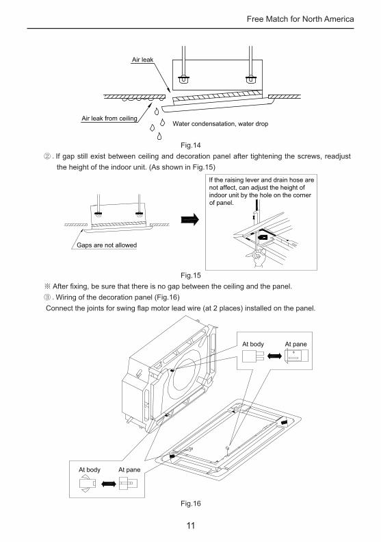
Air leak
Air leak from ceilingWater condensatation, water drop
Fig.14② .If gap still exist between ceiling and decoration panel after tightening the screws, readjust
the height of the indoor unit. (As shown in Fig.15)
If the raising lever and drain hose are not affect, can adjust the height of indoor unit by the hole on the corner of panel.
Gaps are not allowed
Fig.15※ After fixing, be sure that there is no gap between the ceiling and the panel.③ .Wiring of the decoration panel (Fig.16) Connect the joints for swing flap motor lead wire (at 2 places) installed on the panel.
At body At pane
At body At pane
Fig.16
Free Match for North America
12
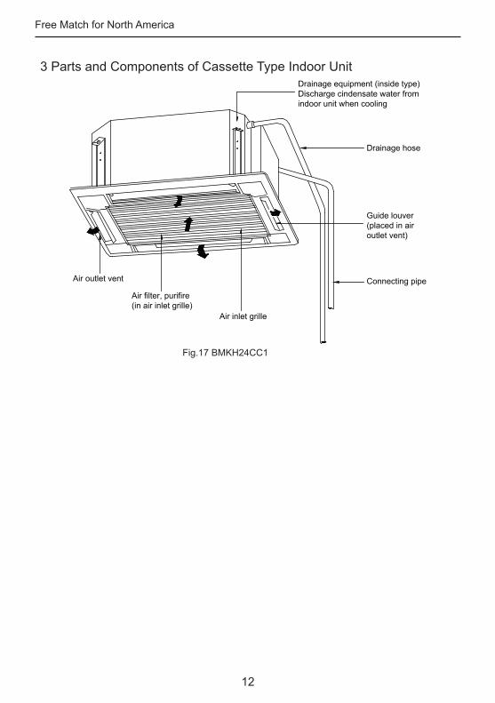
3 Parts and Components of Cassette Type Indoor Unit
Air outlet vent
Air filter, purifire(in air inlet grille)
Air inlet grille
Guide louver(placed in airoutlet vent)
Drainage equipment (inside type)Discharge cindensate water fromindoor unit when cooling
Connecting pipe
Drainage hose
Fig.17 BMKH24CC1
Free Match for North America
13
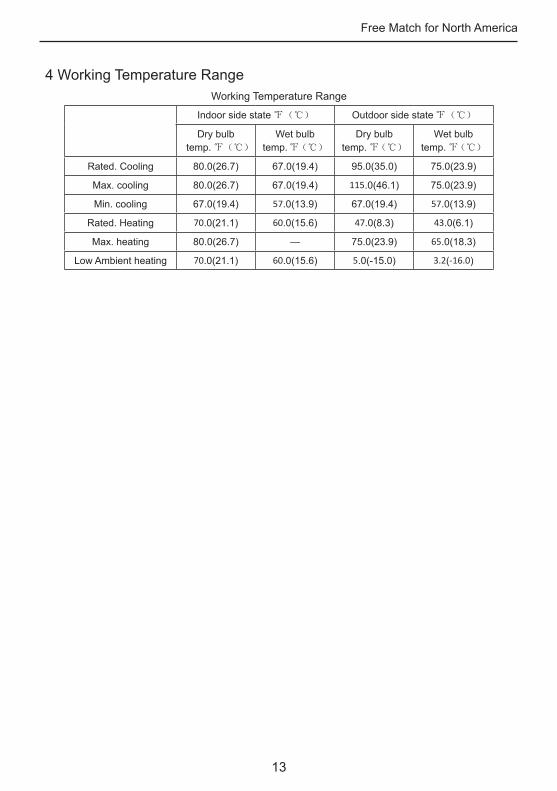
4 Working Temperature RangeWorking Temperature Range
Indoor side state ℉(℃) Outdoor side state ℉(℃)
Dry bulb temp. ℉(℃)
Wet bulb temp. ℉(℃)
Dry bulb temp. ℉(℃)
Wet bulb temp. ℉(℃)
Rated. Cooling 80.0(26.7) 67.0(19.4) 95.0(35.0) 75.0(23.9)
Max. cooling 80.0(26.7) 67.0(19.4) 115.0(46.1) 75.0(23.9)
Min. cooling 67.0(19.4) 57.0(13.9) 67.0(19.4) 57.0(13.9)
Rated. Heating 70.0(21.1) 60.0(15.6) 47.0(8.3) 43.0(6.1)
Max. heating 80.0(26.7) — 75.0(23.9) 65.0(18.3)
Low Ambient heating 70.0(21.1) 60.0(15.6) 5.0(-15.0) 3.2(-16.0)
Free Match for North America
14
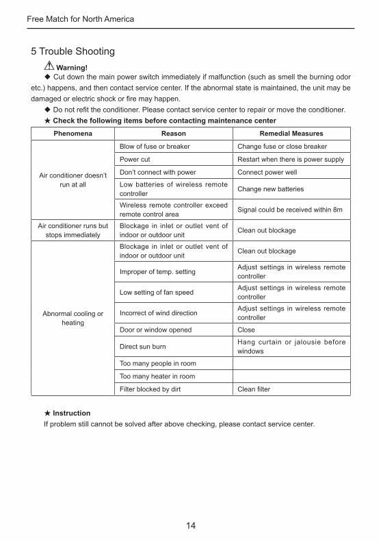
5 Trouble Shooting Warning!
◆ Cut down the main power switch immediately if malfunction (such as smell the burning odor etc.) happens, and then contact service center. If the abnormal state is maintained, the unit may be damaged or electric shock or fire may happen.
◆ Do not refit the conditioner. Please contact service center to repair or move the conditioner.★ Check the following items before contacting maintenance center
Phenomena Reason Remedial Measures
Air conditioner doesn’t run at all
Blow of fuse or breaker Change fuse or close breaker
Power cut Restart when there is power supply
Don’t connect with power Connect power well
Low batteries of wireless remote controller
Change new batteries
Wireless remote controller exceed remote control area
Signal could be received within 8m
Air conditioner runs but stops immediately
Blockage in inlet or outlet vent of indoor or outdoor unit
Clean out blockage
Abnormal cooling or heating
Blockage in inlet or outlet vent of indoor or outdoor unit
Clean out blockage
Improper of temp. settingAdjust settings in wireless remote controller
Low setting of fan speedAdjust settings in wireless remote controller
Incorrect of wind directionAdjust settings in wireless remote controller
Door or window opened Close
Direct sun burnHang curtain or jalousie before windows
Too many people in room
Too many heater in room
Filter blocked by dirt Clean filter
★ InstructionIf problem still cannot be solved after above checking, please contact service center.
Free Match for North America
15
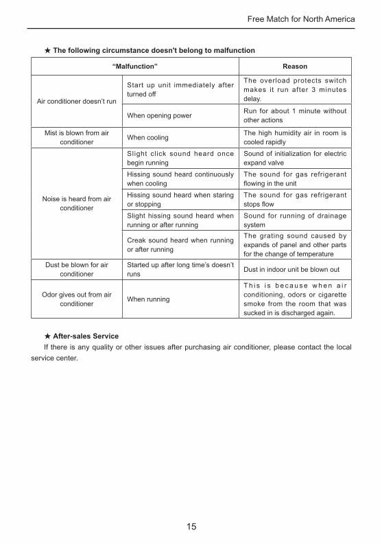
★ The following circumstance doesn't belong to malfunction
“Malfunction” Reason
Air conditioner doesn’t run
Start up unit immediately after turned off
The overload protects switch makes it run after 3 minutes delay.
When opening powerRun for about 1 minute without other actions
Mist is blown from air conditioner
When cooling The high humidity air in room is cooled rapidly
Noise is heard from air conditioner
Slight click sound heard once begin running
Sound of initialization for electric expand valve
Hissing sound heard continuously when cooling
The sound for gas refrigerant flowing in the unit
Hissing sound heard when staring or stopping
The sound for gas refrigerant stops flow
Slight hissing sound heard when running or after running
Sound for running of drainage system
Creak sound heard when running or after running
The grating sound caused by expands of panel and other parts for the change of temperature
Dust be blown for air conditioner
Started up after long time’s doesn’t runs
Dust in indoor unit be blown out
Odor gives out from air conditioner
When running
T h i s i s b e c a u s e w h e n a i r conditioning, odors or cigarette smoke from the room that was sucked in is discharged again.
★ After-sales ServiceIf there is any quality or other issues after purchasing air conditioner, please contact the local
service center.
Free Match for North America
16
6 Maintenance MethodWhen the unit won’t be used for a long time, please cut off the main power supply of air
conditioner.
Warning!◆ Do turn off the unit and cut off the main power supply when cleaning the air conditioner,
otherwise electric shock or harm may happen.◆ It is forbidden to wash air conditioner by water rinsing, otherwise electric shock may happen.
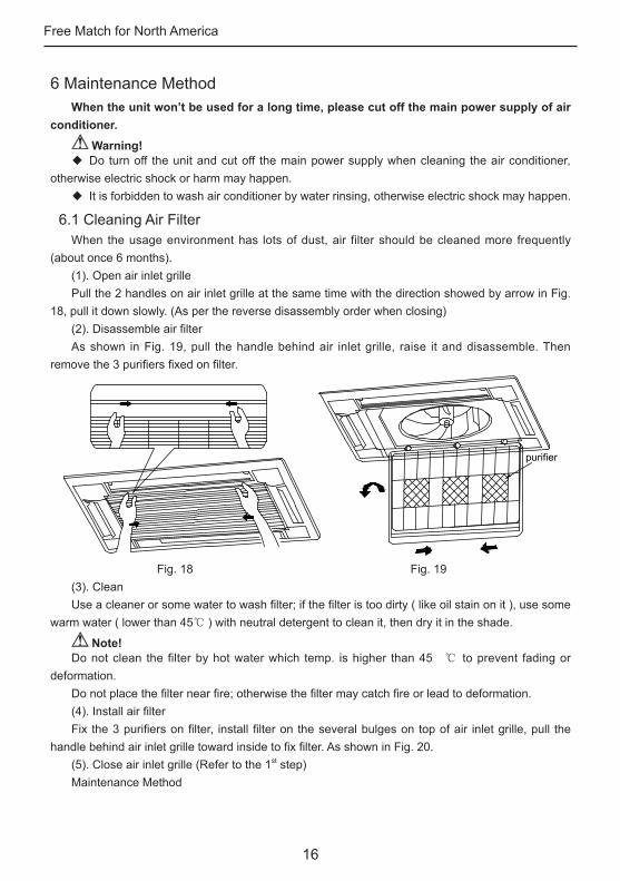
6.1 Cleaning Air FilterWhen the usage environment has lots of dust, air filter should be cleaned more frequently
(about once 6 months). (1). Open air inlet grillePull the 2 handles on air inlet grille at the same time with the direction showed by arrow in Fig.
18, pull it down slowly. (As per the reverse disassembly order when closing)(2). Disassemble air filterAs shown in Fig. 19, pull the handle behind air inlet grille, raise it and disassemble. Then
remove the 3 purifiers fixed on filter.
purifier
Fig. 18 Fig. 19(3). CleanUse a cleaner or some water to wash filter; if the filter is too dirty ( like oil stain on it ), use some
warm water ( lower than 45℃ ) with neutral detergent to clean it, then dry it in the shade.
Note!Do not clean the filter by hot water which temp. is higher than 45 ℃ to prevent fading or
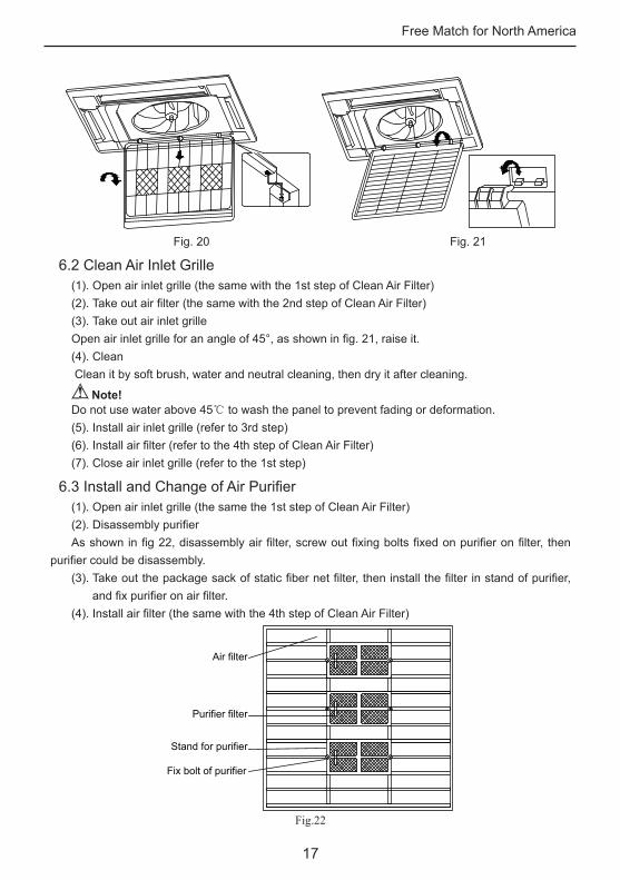
deformation.Do not place the filter near fire; otherwise the filter may catch fire or lead to deformation.(4). Install air filterFix the 3 purifiers on filter, install filter on the several bulges on top of air inlet grille, pull the
handle behind air inlet grille toward inside to fix filter. As shown in Fig. 20.(5). Close air inlet grille (Refer to the 1st step)Maintenance Method
Free Match for North America
17
Fig. 20 Fig. 21
6.2 Clean Air Inlet Grille(1). Open air inlet grille (the same with the 1st step of Clean Air Filter)(2). Take out air filter (the same with the 2nd step of Clean Air Filter)(3). Take out air inlet grilleOpen air inlet grille for an angle of 45°, as shown in fig. 21, raise it.(4). Clean Clean it by soft brush, water and neutral cleaning, then dry it after cleaning.
Note!Do not use water above 45℃ to wash the panel to prevent fading or deformation.(5). Install air inlet grille (refer to 3rd step)(6). Install air filter (refer to the 4th step of Clean Air Filter)(7). Close air inlet grille (refer to the 1st step)
6.3 Install and Change of Air Purifier(1). Open air inlet grille (the same the 1st step of Clean Air Filter)(2). Disassembly purifierAs shown in fig 22, disassembly air filter, screw out fixing bolts fixed on purifier on filter, then
purifier could be disassembly.(3). Take out the package sack of static fiber net filter, then install the filter in stand of purifier,
and fix purifier on air filter.(4). Install air filter (the same with the 4th step of Clean Air Filter)
Fix bolt of purifier
Stand for purifier
Purifier filter
Air filter
Fig.22
Free Match for North America
18
Function and usage period for air purifying◆ Adsorb CO, CO2, benzene, aldehydes and odor of gasoline etc..◆ Adsorb poisonous material that is smaller than 1μm in air, as dust, pollen, bacteria, and
virus.◆ Usage period is 6 months to 1 year. If it is necessary to be changed, purchase new purifier
in the nearest Blueridge special engaged maintenance center.
6.4 Clean Outlet Vent and Surface Panel◆ Clean the surface panel by soft dry cloth or wet cloth with neutral scourer.◆ It is forbidden to clean surface panel by gasoline, benzene, diluents, cleansing powder etc..◆ If the guide louver is too dirty, it may be removed to be cleaned. (As narrated below)Disassembly and installation of guide louver(1). Disassemble guide louverScrew bolts in both ends of guide louver to loose.
Note!Do not forcibly wipe guide louver when cleaning, otherwise painted surface layer would fall off.(2). Install guide louverRotate guide louver slightly could install the protruding edge of both end into grooves on both
end of guide louver, and then tighten bolts.
6.5 Maintenance before or after Seasonal UseCheck before the seasonal use◆ Check if there is blockage at inlet or outlet of air conditioner.◆ Check if the earthing wire has been earthed reliably.◆ Check if the air filter has been installed well.◆ In order to start up the air conditioner smoothly after long time’s turned off, turn on the main
power supply 8 hours before turning on the air conditioner.Maintenance after seasonal use◆ Clean filter and body of air conditioner.◆ Cut off the main power supply of air conditioner.◆ The cooling or heating capacity and sound level are tested before leaving factory.◆ If the parameter changes, refer to the data offered on nameplate.