Embed Size (px)
Citation preview
Free-Space and Indoor Wireless Optical Communication Systems
Steve HranilovicDept. Electrical & Computer EngineeringMcMaster University
Nortel Networks Institute Distinguished Seminar Series
June 14, 2007

Outline
Research GroupIntroduction
Definitions and Applications for OW and FSO LinksIndoor Optical Wireless Communications
Optical intensity channel, amplitude constraintsDSDBinary-Level MIMO SystemPrototype
FSO LinksFSO Channel model, challengesOutage Capacity Design MethodologyExperimental Links
Conclusions & Future Directions

Research Group
Free-Space Optical Communication Algorithms Laboratory
1. Modem design for FSO and indoor optical wireless• Theory and simulation studies
2. Prototype Demonstrations
What is Optical Wireless?
Unguided or Wirelesscommunications using optical band emissions (both coherent or incoherent)
Terminology:Optical Wireless (OW)Free-Space Optics (FSO)
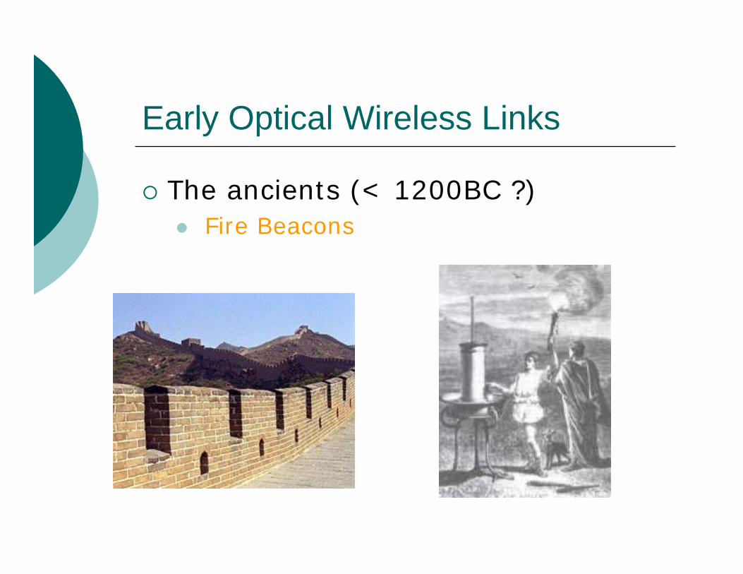
Early Optical Wireless Links
The ancients (< 1200BC ?)Fire Beacons
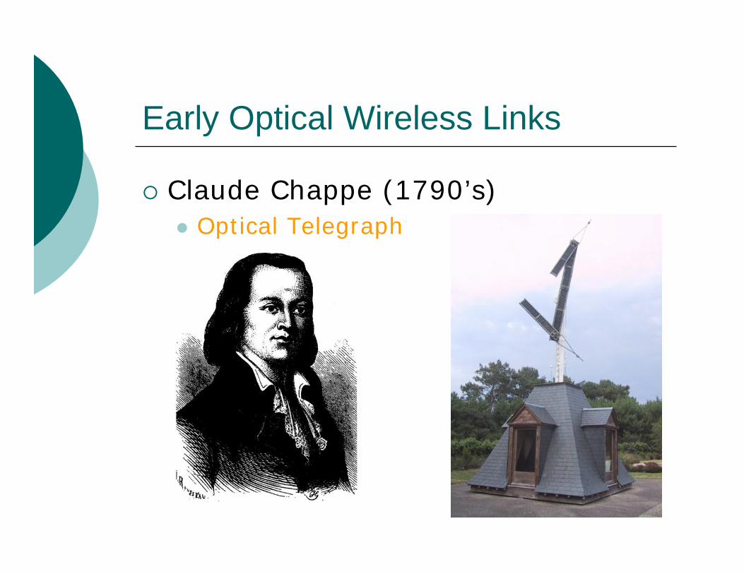
Early Optical Wireless Links
Claude Chappe (1790’s)Optical Telegraph
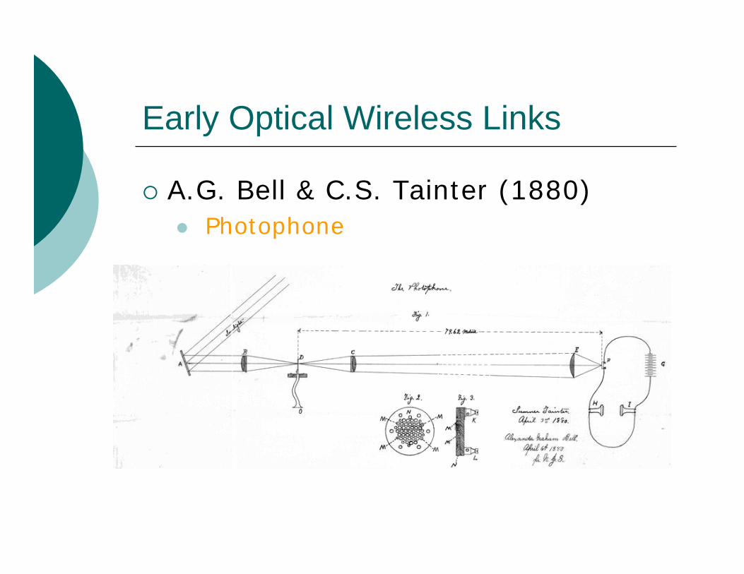
Early Optical Wireless Links
A.G. Bell & C.S. Tainter (1880)Photophone
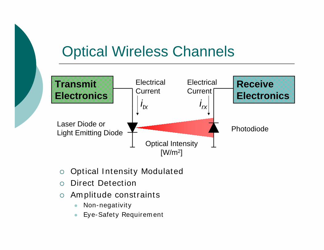
Optical Wireless Channels
Optical Intensity ModulatedDirect DetectionAmplitude constraints
Non-negativityEye-Safety Requirement
Transmit Electronics
Receive Electronics
itx irx
Photodiode
Optical Intensity[W/m2]
ElectricalCurrent
Laser Diode orLight Emitting Diode
ElectricalCurrent

Comparison of OW versus RF
All electrical signals at baseband!
Data In Data Out
IF Synthesizer RF Synthesizer RF Synthesizer
PA IR/LNA
IF Synthesizer
Data In Data Out
ZG

Advantages/Disadvantages of OW
AdvantagesAdvantagesLow cost, base-band circuit designUnregulated bandwidthHigh date rates (Gbps)Inherently high-security, less multiaccess interference
DisadvantagesDisadvantagesCannot pass through wallsSensitive to blockingLimited Transmit Power
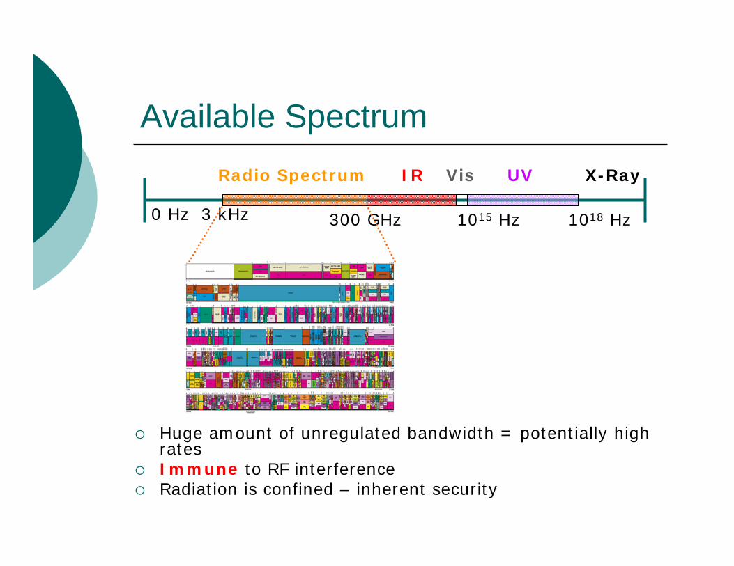
Available Spectrum
Huge amount of unregulated bandwidth = potentially high ratesImmune to RF interferenceRadiation is confined – inherent security
0 Hz 3 kHz 300 GHz 1015 Hz 1018 Hz
Radio Spectrum Vis UV X-RayIR

Eye-Safety Requirement
At near IR (λ = 700-1000 nm), human eye focuses radiation much like visible wavelengthsCornea nearly opaque for λ > 1400 nmAverage transmitted optical power is limited
Optic Nerve
Retina
Cornea
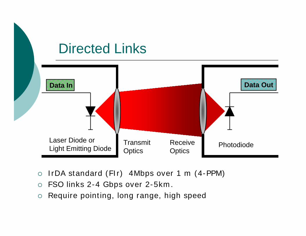
Directed Links
Data In Data Out
TransmitOptics
ReceiveOptics
PhotodiodeLaser Diode orLight Emitting Diode
IrDA standard (FIr) 4Mbps over 1 m (4-PPM)FSO links 2-4 Gbps over 2-5km.Require pointing, long range, high speed
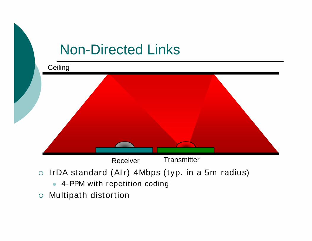
Non-Directed Links
TransmitterReceiver
Ceiling
IrDA standard (AIr) 4Mbps (typ. in a 5m radius)4-PPM with repetition coding
Multipath distortion
Short range (cm – m)Medium range (m – 10 m)Long range (km)
Applications

Chip-to-Chip Signalling
High speed link to main memory and video

Multi-pixelHigh RateHigh interconnect density
MemoryCPU
Low PowerPower supply independentNo EMI
Multi-Element Chip-to-Chip Interface
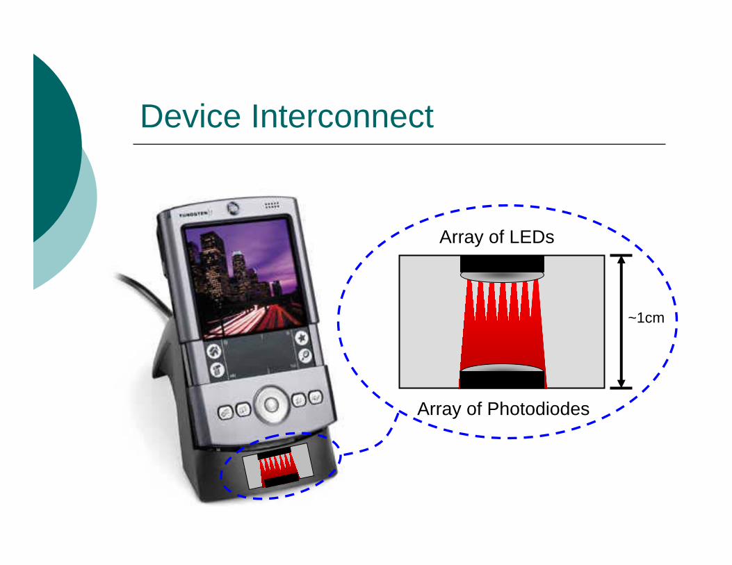
Device Interconnect
Array of LEDs
Array of Photodiodes
~1cm
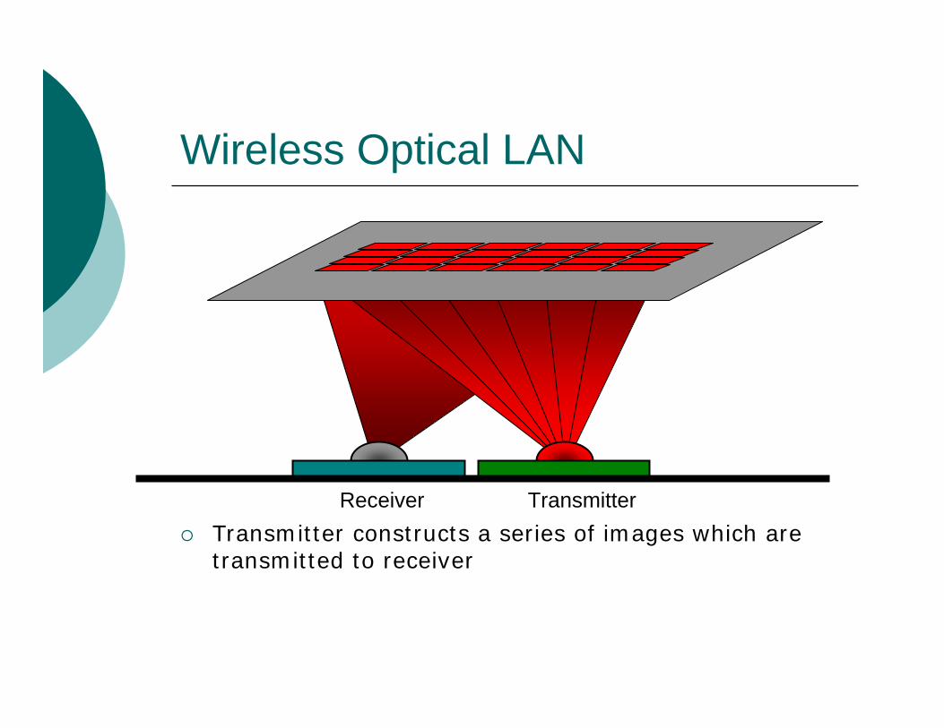
Wireless Optical LAN
Transmitter constructs a series of images which are transmitted to receiver
Receiver Transmitter
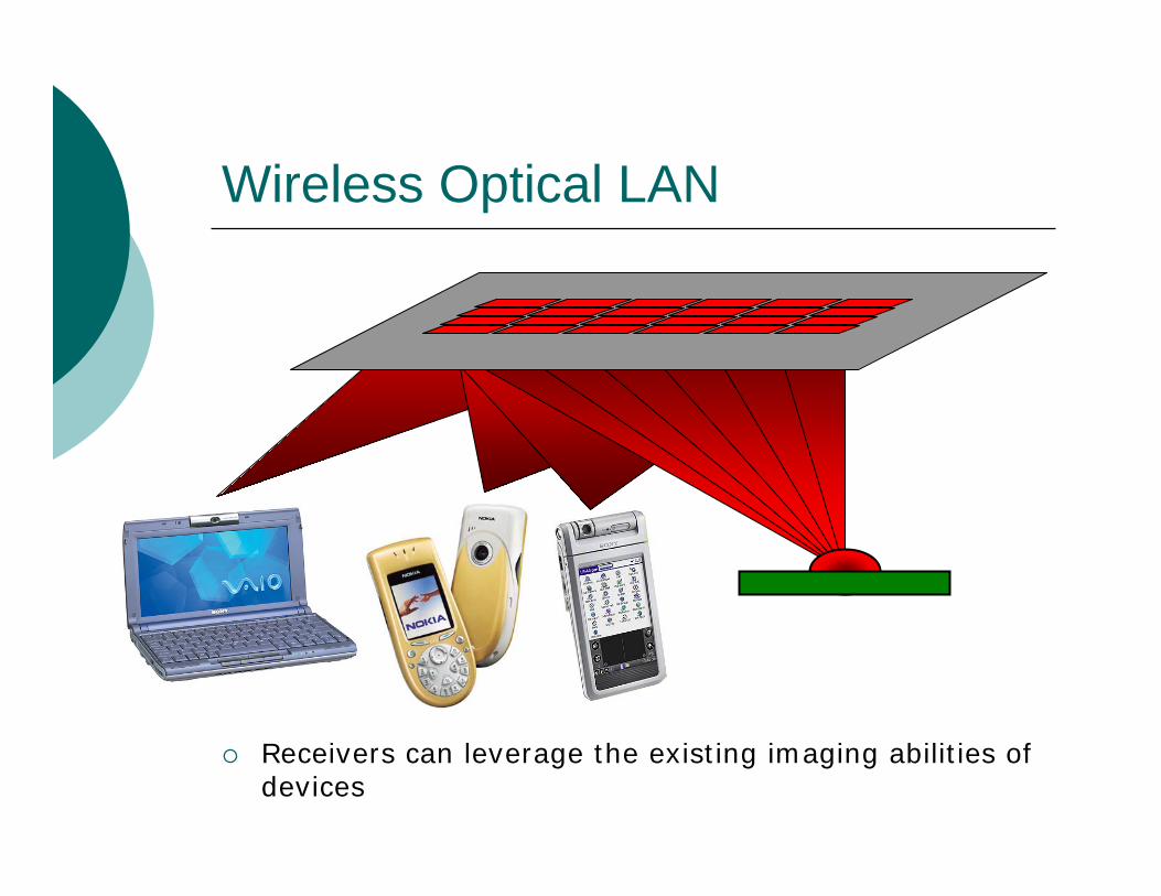
Wireless Optical LAN
Receivers can leverage the existing imaging abilities of devices

Optical Wireless LAN
Room illumination can be harnessed to provide inexpensive, high rate links.

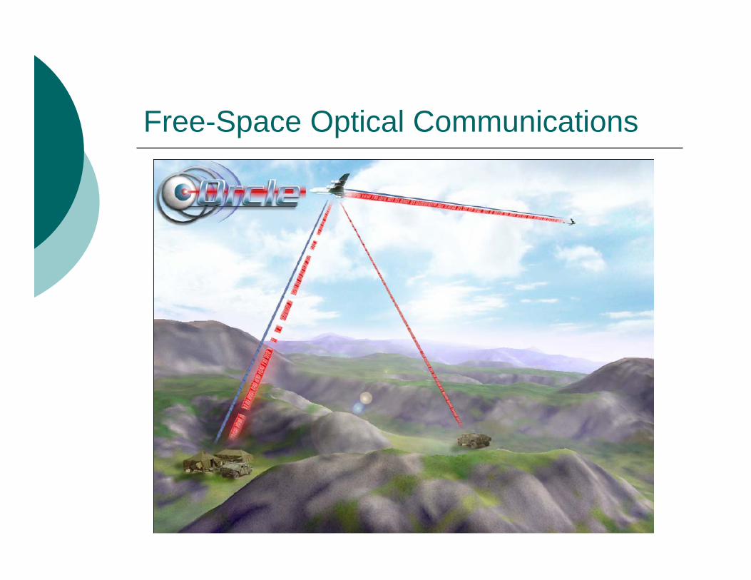
Free-Space Optical Communications
High-speed (<2 Gbps) fiber extension over 1-4km
Free-Space Optical Communications

Free-Space Optical Communications
ESA Artemis experimentLEO to GEO communication (link range approx 45,000 km!)
Indoor Optical Wireless Links
Indoor OW links are an attractive compliment to existing RF links
Must take into account amplitude constraints!
Amplitude non-negativity constraintAverage amplitude constraint

Ceiling
Line-of-Sight Architecture
TX
RX
High bandwidthHigh received SNRLow user mobility (w/o tracking)

Diffuse Indoor OW Architecture
High user mobility at a cost of low received optical power and multipath distortionNo fading for indoor OW communications
Ceiling
RX TX

Multi-Spot Diffusing Architecture
Ceiling
RX TX
Higher receiver SNRLow multipath due to quasi-LOS pathComplex transmitter must be designed for each room
Indoor OW Topologies
Point-to-point links have high bandwidth and SNR
Require pointing
Diffuse links permit mobility At expense of bandwidth and SNR
Multispot Diffusing links permit mobility and good SNR
Complex transmitter which cannot be easily modified for different rooms.

Spot
Ceiling
RX
Dynamic Spot Diffusing Channel
TX
Floor
Spot
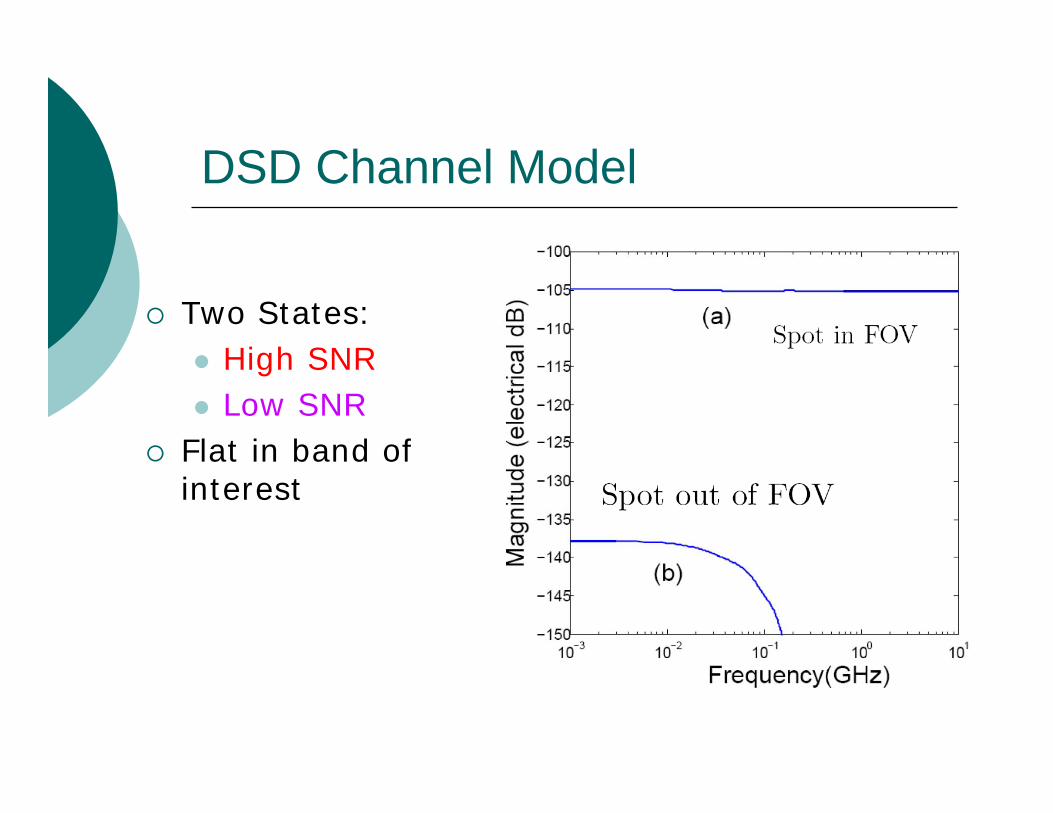
DSD Channel Model
Two States:High SNRLow SNR
Flat in band of interest

DSD Channel Capacity
Channel Coding
DSD channel well modelled as an erasure channel
Fixed rates codes are not appropriate
Rateless Codes (Fountain Codes)Do not require knowledge of erasureprobability
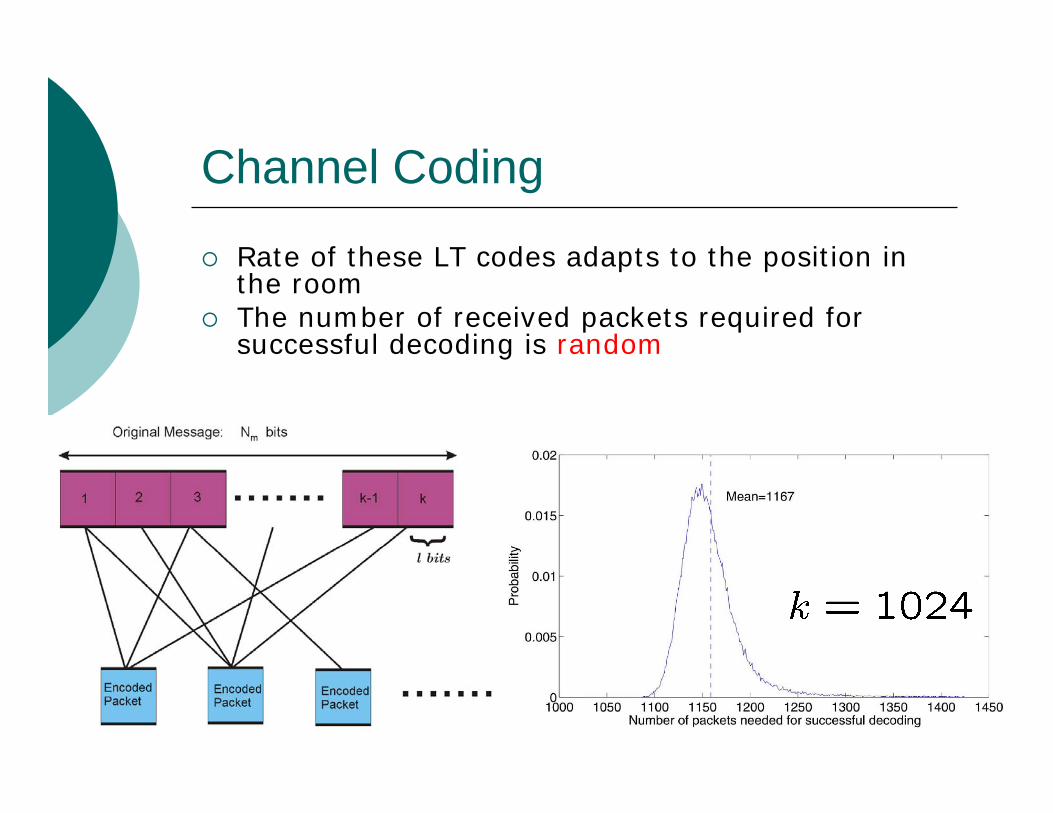
Channel Coding
Rate of these LT codes adapts to the position in the roomThe number of received packets required for successful decoding is random
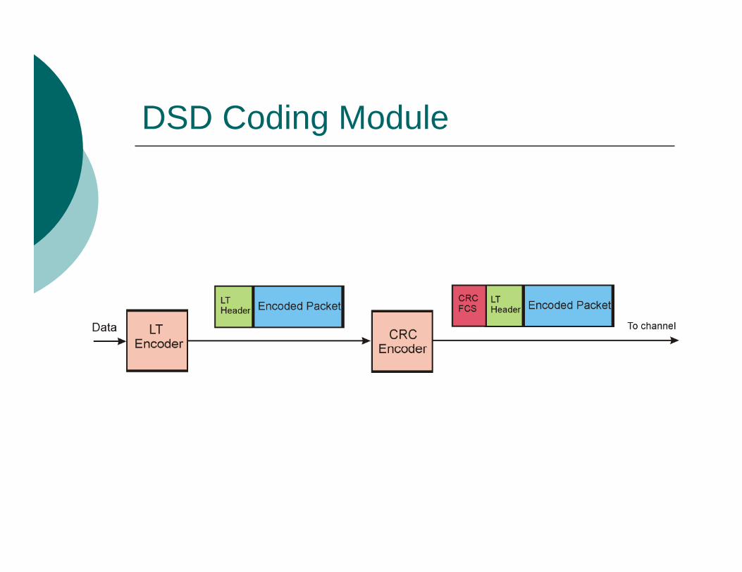
DSD Coding Module
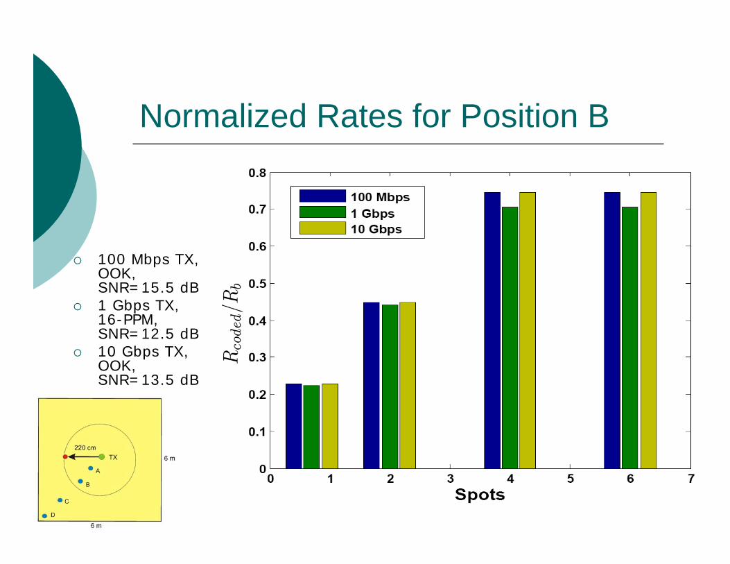
Normalized Rates for Position B
100 Mbps TX, OOK, SNR=15.5 dB1 Gbps TX,16-PPM, SNR=12.5 dB10 Gbps TX, OOK, SNR=13.5 dB

Single Element Systems
Spectral efficiency improved by careful pulse selection
Transmitter
Receiver

Multi-Pixel Optical Link
Transmitters
Receivers
On order of 1000x1000
On order of 1000x1000
Transmit a series of images !
Spatio-temporal coding

MIMO Wireless Optical Channel
Pixel shapes and optics modelled by a lowpass point-spread function h(x,y)High resolution SLM’s exist

MIMO Wireless Optical Channel

Pixelated Wireless Optical Channel
Spatial Discrete Multitone Spatial Discrete Multitone ModulationModulation (SDMT)
Data loaded in low spatial frequency Append cyclic extension around imageWater pouring over spatial frequency bins
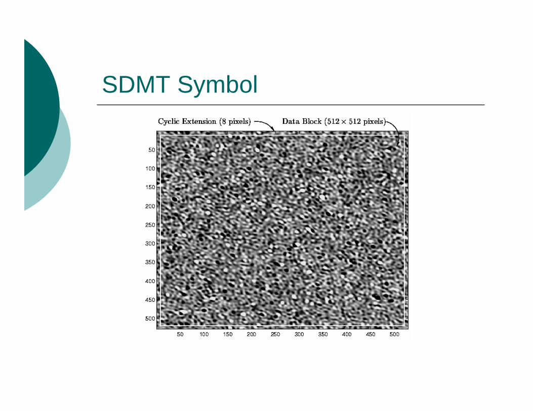
SDMT Symbol

Out-of-Band Techniques
Problems:Non-negativity constraintNeed high-dynamic range SLM
Proposed Solution:High-speed binary-level SLMs exist!Use the degrees of freedom in the out-of-band spectrum to satisfy amplitude constraintsΔ-Σ modulation in space
Shape quantization noise out-of-band

Error Diffusion Halftoning

Halftoned Spatial Discrete Multitone
Image Processing:Feedback filter J(k1,k2) shapes quantization noise to high frequencies out of perceptual range
Optical Communication:Feedback filter J(k1,k2) shapes quantization noise to high frequencies which are attenuated by channel
Choose J() to maximize the channel capacity

Optical Power Limited System

Quantization Noise Limited System

Capacity Results
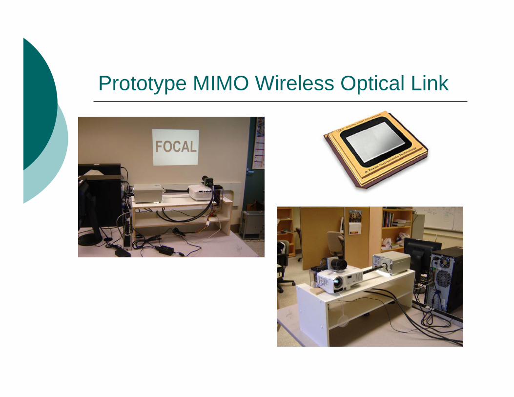
Prototype MIMO Wireless Optical Link

Free-Space Optical Links
There is a great need for high-speed (Gbps) wireless access medium
It is estimated that 75% of commercial buildings in the US are within 1 km of a major fiber trunk, but only 5% of these are connected to that trunk.
FSO Links provide a virtual extension of backbone fiber network at a comparatively low cost!
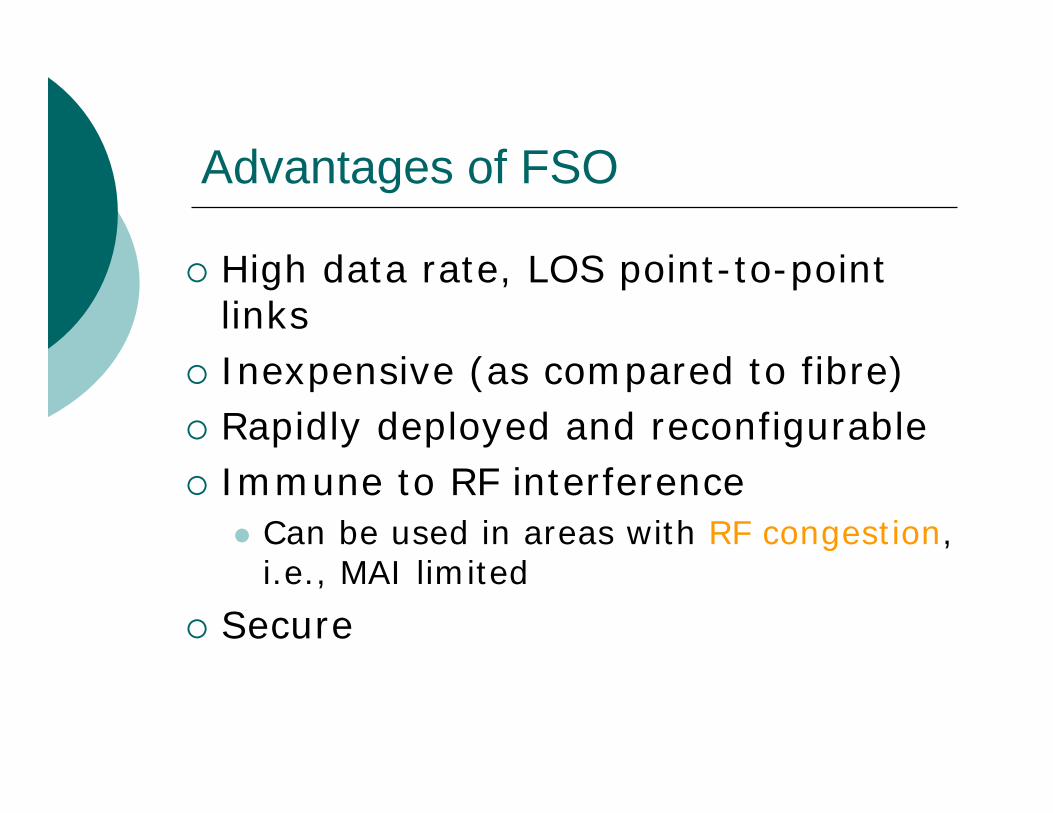
Advantages of FSO
High data rate, LOS point-to-point linksInexpensive (as compared to fibre)Rapidly deployed and reconfigurableImmune to RF interference
Can be used in areas with RF congestion, i.e., MAI limited
Secure

FSO Link Impairments

The 3 R’s of FSO
RangeRange
ReliabilityReliability RateRate
WEATHER!WEATHER!

Weather
Denver Colorado, Fog events

FSO Range and Rates
Commercial systems operate at ranges of 1-4 km at rates < 2 GbpsSingle and Multiple beam systemsActive tracking is employed in more expensive systems to mitigate pointing errors
Inexpensive systems use a wide beam width at cost of lower SNR (i.e. range)

FSO Fading
Amplitude fluctuation due to variation of refractive index of air along propagation pathSlow fading
Coherence time on order of 10 ms while bit period is on order of 1 ns!
Increases drastically with range

FSO Reliability
FSO customers roughly divided according to reliability requirements
Carrier-Class CustomersService providers such as Bell and RogersAvailability requirements of 99.999% (5 nines)
Enterprise CustomersUniversity campuses, hospitals, companiesAvailability requirements 99%

FSO Link Outage Capacity Based Design
QuestionQuestion:For a given range, how to select beam width to maximize rate for a given reliability?
Reliability is quantified by probability of outage event

FSO Link Outage Capacity Based Design
AnswerAnswer: (partial)Wide Beam: mitigates pointing error at expense of low SNR at receiver

FSO Link Outage Capacity Based Design
AnswerAnswer: (partial)Narrow Beam: More severe pointing error, higher instantaneous SNR at receiver

Achievable Pairs (Pout, R0)
Light fog, log-normal fading (σR
2=0.1), P=16dBm

FSO Testbed at McMaster University
200m
Brandon Hall
McMasterInnovation
Park
Main St.
Hwy. 403
Google Maps, 2007
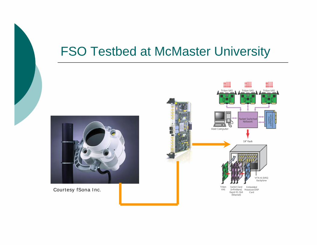
FSO Testbed at McMaster University
Courtesy fSona Inc.

Conclusions
Optical wireless is a viable compliment to RF communications
Large rates are available due to vast amounts of unregulated bandwidthImmune to RF interference and cross-talkRapidly deployable and reconfigurable Gbps links

Current and Future Directions
Hybrid RF-FSO linksTo improve reliability of linkFor mitigation of interference limited networks (frequency planning)For use in backhaul of WiMAX and like networks
MIMO FSO communicationsIndoor Optical Impulse Modulated Wireless Systems

Thanks …To my students for their hard work!
Ahmed A. Farid (Ph.D.)Mohamed D.A. Mohamed (Ph.D.)Weiwei Kang (M.A.Sc.)Farhad Khozeimeh (M.A.Sc.)Awad Dabbo (M.A.Sc.)

Contact
Prof. Steve HranilovicDept. Electrical and Computer EngineeringMcMaster University
Email: hranilovic @ mcmcaster.ca