Embed Size (px)
Citation preview

Free-Space Optics Based Wireless Sensor Netw ork Design
P. Verma, A. K. Ghosh and A. Venugopalan
Telecommunication Engineering Program
School of Electrical and Computer Engineering
University of Oklahoma Tulsa
Tulsa, OK 74135.
Abstract
This paper proposes an FSO-based mobile sensor network that is not subject to RF interference
common to wireless sensor networks. FSO-based mobile sensor networks can potentially be used
in a battlefield where security of communication, including freedom from susceptibility to
enemy-induced jamming, is important. The paper discusses the design of nodes containing
multiple transceivers composed of LEDs and photo detectors. Results of initial experiments are
included. The work reported in this paper is part of an ongoing investigation on mobile FSO
networks, including the design of efficient protocols that can allow the mobile sensor nodes to
function as a mesh network permitting information exchange among nodes directly and,
possibly, through an intermediate node.
Introduction:
A wireless sensor network (WSN) that comprises of small-scale, low-cost processors with
integrated sensing, communication and data processing capabilities is popular in many domains
such as battlefield surveillance, habitat monitoring, home automation and health-care
applications [1,2]. All the WSNs use radio frequency (RF) for communications. Thus, in an
environment where there is an unacceptable level of RF interference, or where the leakage of RF
has the potential to compromise security, it is undesirable to deploy RF based WSNs. In
environments with electronic instruments that are susceptible to RF interference, the presence of
RF from a WSN might lead to malfunctioning of such instruments resulting in potentially
catastrophic consequences. Several papers have discussed various approaches to building WSNs
using optical wireless or free-space optical communications [3-10].
In this paper, we discuss our research on developing a low-cost free space optics (FSO) based
WSN in situations where an RF based WSN is not desirable. We have developed a low-cost free-
space optical ID system for high-security identification and interrogation [11] in our laboratory.
Our focus in this paper is on extending the optical ID system using angle-diversity
photodetectors [12-14] so that sensor-to-sensor wireless communication is possible over a
distance of several meters. The angle diversity photodetectors also allow for a limited amount of
mobility between the sensor nodes on a planar surface.
Optical ID System:
The optical ID system is developed for securely interrogating an optical tag using a laser beam
RTO-MP-IST-083 P3 - 1
UNCLASSIFIED/UNLIMITED
UNCLASSIFIED/UNLIMITED

based optical wireless communication system. The Optical ID system comprises of two
components, an optical reader and a tag. Figures 1 and 2 present block diagrams of how the tag
and reader systems are made. Only sending an encrypted message from the optical reader can
activate this tag. When we want to acquire data from the tag, we turn on the optical reader. The
optical reader sends a coded light pulse to the tag. The tag, on receiving the light pulse, verifies
that it is from the reader and then activates the transmitter of the tag. The tag can be interfaced to
a sensor. The information stored in the sensor node is processed and digitized for transmission.
When interrogated by the reader the information from the sensor is provided to a transmitter
circuit. The transmitter modulates and transmits the information at a suitable frequency. The
optical reader locks in to this modulating frequency and acquires the sensor information.
Fig 1: A block diagram of an optical tag with a sensor
Fig 2: A Block diagram of the optical reader.
Our optical ID system has been built with off-the-shelf components at a moderate cost to provide
a high degree of security. One aspect of security is provided by means of a directional laser beam
and the other part through an RSA encryption scheme. We use low-cost low-power diode lasers
with a wavelength of 635 nm. The receivers are made with 1 cm diameter Silicon p-i-n
photodiodes. The system operates at a data rate of about 20 Kbps. The bit rate chosen keeps the
cost down and is adequate for our reader-tag system that needs to send only a few hundred
kilobytes of information. We carried out several experiments to determine our system’s
performance under various conditions.
Switch
Display Table
Lookup Decoder
Low
Noise
Amplifier Photodiode
Driver
&
Modulator
Coder
Laser
Sensor ADC Switch Driver
&
Modulator
Decoder Low
Noise
Amplifier
Photodiode
Laser
Free-Space Optics Based Wireless Sensor Network Design
P3 - 2 RTO-MP-IST-083
UNCLASSIFIED/UNLIMITED
UNCLASSIFIED/UNLIMITED

To determine the performance of the system at various distances and states of alignment, we
characterized the beam emitted by the laser. We find that the minimum spot sizes are W0x = 66.2
µm and W0y = 242 µm along the x and y axes respectively. The beam divergence angle
is calculated to be 4.28 mrad. This highly paraxial beam provides our system with a large amount
of security. The optical power received by the tag from the reader with a variation in distance is
also studied. The value of normalized received power decreases to less than or equal to 0.5
when when the tag and reader are separated by 5.15 m. Thus we find that our optical-ID works
well if the distance between the reader and the tag is kept below 5.15 m. We find that at a
distance of 3 m a lateral offset of ±3.5 mm from the axis can be tolerated without sacrificing
80% of the received power. From BER measurement we find that a decrease of 20% power at the
distance of z = 3 m does not degrade the BER. The frequency response of the laser plus photo
detector combination has been determined. The 3 dB cutoff frequency measured lies between 50
KHz to 220 KHz depending on the manner of modulating the laser driver.
Fig 3: Bit Error Rate versus Distance for transmission at 19.2 Kbps
To understand the performance of our intensity modulated direct-detection optical-ID system we
measured the bit-error-rate in a typical set-up. Tests were conducted using varying bit rates and
data sequences. Bit error rate is a strong function of signal power. As we move the tag further
away from the reader, the power received by the tag decreases along with the signal to noise
ratio. Beyond a certain distance, we can no longer recover the signal. In our experimental
investigation, we have measured the limit on the distance beyond which the system
exhibits significant loss of packets. The variation of the bit-error rate with distance is plotted in
Fig. 3. We find that we can use the optical ID with an error rate less than 10-9
when the distance
between the tag and the reader is up to 4.6 m.
Free-Space Optics Based Wireless Sensor Network Design
RTO-MP-IST-083 P3 - 3
UNCLASSIFIED/UNLIMITED
UNCLASSIFIED/UNLIMITED

FSO System based WSN:
Based on the design of the short distance, point-to-point free space optical ID system in our
laboratory, we envision a WSN where each sensor node is equipped with an optical transmitter
and an optical receiver made with an array of p-i-n photodiodes arranged as shown in Fig. 4. We
assume that the sensor-nodes are distributed on a planar surface, as for example, the floor of a
workshop or a level field. Each transmitter emits a horizontal beam of light encoded with its
message for other nodes. If illuminated by this beam, the photodiodes of another node can
receive the message in the manner of a free-space optical communication system [15]. Thus, our
system is based on line-of-sight optical communications rather than the diffused or scattered
light based indoor optical communication systems discussed in Refs. [12-14, 16]. Major
advantages of line-of-sight communications are large distances between nodes and freedom from
multipath interference or fading.
Fig. 4: Block diagram of a sensor node equipped with an optical transceivers.
Unlike the optical ID system discussed earlier, the proposed WSN system uses superluminescent
light emitting diodes (SLED) in its transmitter. These SLEDs are capable of emitting light of
high intensity (100-2500 mW) over a cone of fairly large angle. They are reasonably fast having
rise times of the order of 80 ns [17]. We use an intensity modulated subcarrier scheme in which
each transmitter is assigned its unique subcarrier frequency in the MHz range. However it is also
possible to use code-division multiplexing.
For the receiving antenna, we have designed an angle-diversity combination of photodiodes
connected to each node of the WSN [12]. The photodiodes are arranged in one plane capable of
direct detection of light from a SLED located in the plane. All the p-i-n photodiodes in the
Free-Space Optics Based Wireless Sensor Network Design
P3 - 4 RTO-MP-IST-083
UNCLASSIFIED/UNLIMITED
UNCLASSIFIED/UNLIMITED
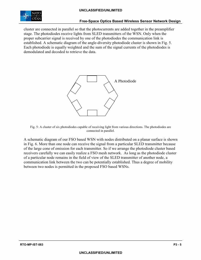
cluster are connected in parallel so that the photocurrents are added together in the preamplifier
stage. The photodiodes receive lights from SLED transmitters of the WSN. Only when the
proper subcarrier signal is received by one of the photodiodes the communication link is
established. A schematic diagram of the angle-diversity photodiode cluster is shown in Fig. 5.
Each photodiode is equally weighted and the sum of the signal currents of the photodiodes is
demodulated and decoded to retrieve the data.
Fig. 5: A cluster of six photodiodes capable of receiving light from various directions. The photodiodes are
connected in parallel.
A schematic diagram of our FSO based WSN with nodes distributed on a planar surface is shown
in Fig. 6. More than one node can receive the signal from a particular SLED transmitter because
of the large cone of emission for each transmitter. So if we arrange the photodiode cluster based
receivers carefully we can easily realize a FSO mesh network. As long as the photodiode cluster
of a particular node remains in the field of view of the SLED transmitter of another node, a
communication link between the two can be potentially established. Thus a degree of mobility
between two nodes is permitted in the proposed FSO based WSNs.
A Photodiode
Free-Space Optics Based Wireless Sensor Network Design
RTO-MP-IST-083 P3 - 5
UNCLASSIFIED/UNLIMITED
UNCLASSIFIED/UNLIMITED

Fig. 6: A FSO based WSN with three sensor nodes with node 1 talking to node 2 and node 3 talking to node 1.
Design:
At first we built a FSO system with a laser based transmitter and a cluster of identical p-i-n
photodiodes as shown in Figs. 4 and 5. We combined several reverse-biased photodiodes in
parallel with a simple op amp based transimpedance preamplifier. The bandwidth of the
preamplifier was kept much lower than that of the photodiodes. As a result, the bandwidth of the
multiple photodiodes and the transimpedance stage weakly dependent on the number of
photodiodes used as shown in the frequency response in Fig. 7. In Fig. 7 we depict the frequency
response of a receiver with a single p-i-n diode along with those from receivers with 3 or 5
identical p-i-n diodes connected in parallel. The bandwidth of the optical receiver with a single
diode is 65 KHz whereas the bandwidth of a receiver with 3 photodiodes in parallel is 58 KHz.
When the number of photodiodes is increased to five the overall bandwidth decreases to 47 KHz.
The main reason for the decrease is the increase of the capacitance of the reverse biased
Sensor
Node 1
SLED
Photodiode
cluster
Sensor
Node 2
Sensor
Node 3
Free-Space Optics Based Wireless Sensor Network Design
P3 - 6 RTO-MP-IST-083
UNCLASSIFIED/UNLIMITED
UNCLASSIFIED/UNLIMITED

photodiodes connected in parallel. This decrease is modeled in the calculation of the signal to
noise ratio of our optical receivers.
Fig. 7: Frequency response of an optical receiver with multiple photodiodes connected in parallel.
To quantify the potential advantage receiver design with identical photodiodes connected in
parallel, we calculate the signal to noise ratio. We assume that the light beam coming to a
photodiode cluster is a uniform plane wave whose direction of propagation lies in the plane
containing the axes of the photodiodes. We assume that the intensity Iin of the input beam is
modulated sinusoidally by a signal of frequency ωs so that
Iin(t) I0 1 m2 /2 2mexp( j st) (1)
where m is the modulation index and I0 is a constant. If the area of a photodiode is a and the half
angle of the field of view of a photodiode is φ the optical power received by the photodiode is
Iinacos( )rect( , ) (2)
where θ is the angle between the axis of the photodiode and the propagation vector of the
incoming wave and rect(θ,φ) = 1 for –φ < θ < φ and zero otherwise. Considering Eq. (2) and the
fact that there are N photodetectors with an angle α = 2π/N between them we can write that the
Free-Space Optics Based Wireless Sensor Network Design
RTO-MP-IST-083 P3 - 7
UNCLASSIFIED/UNLIMITED
UNCLASSIFIED/UNLIMITED

total signal current generated by the photodiode cluster is given by
isig(t) 2mRIoafN ( )exp( j st) (3)
where R is the average responsivity of the photodiodes and angle-diversity factor
fN ( ) rect( , /2) cos( i )rect( i , )i 1
N
. (4)
Thus the signal to noise ratio at the output of the receiver is given by
SNR2(mRI0afN ( ))2
ish,N2 ith,N
2 (5)
where ish,N2 and ith,N
2 represent the mean square values of the shot noise and thermal noise
currents, respectively. The mean square value of the shot noise current is given by
ish,N2 2qRI0a(1 m2 /2) fN( )BN 2qRIBackaNBN 2qidarkNBN (6)
where BN is the noise equivalent bandwidth of the photodiode cluster combined with the
amplifier, Iback is the average background light intensity, idark is the average dark current in the
photodiodes and q is the electronic charge. The mean square value of the thermal noise current is
given by
ith,N2 4kTBNF /RL (7)
where k is Boltzmann constant, T is the device temperature in oK, RL is the load resistance and F
is the amplifier noise factor.
If the field of view of each photodiode is large then the angle diversity factor in Eq. (4) can be
greater than unity and increase rapidly with N. When φ = π/2 the angle of view of each
photodiode is the maximum and each detector can receive a beam of light easily for –π/2 < θ <
π/2. The same beam of light can then be detected by several photodiodes and the value of the
total signal current in the receiver increases. In Fig. 8 we show the behavior of fN(0) as a function
of N when φ = π/2. However, if the field of view of the photodiodes is narrow then each
photodiode acts individually and fN = 1.
From Eq. (5) we find that when the field of view is wide the signal power at the output of the
receiver increases by a factor of fN2 whereas the power of the shot and thermal noise grows by
factors of fN and N. In this situation the signal to noise ratio of the photodiode array can increase
with N. But if the field of view of each photodiode is narrow then an increase of photodiodes
increases the amount of shot noise and the signal to noise ratio decreases with N. In Fig. 9 we
show the upper and lower bounds on the signal to ratio for a particular case study. When the
photodiodes have a field of view φ < π/2 the signal to noise ratio will remain in between the two
Free-Space Optics Based Wireless Sensor Network Design
P3 - 8 RTO-MP-IST-083
UNCLASSIFIED/UNLIMITED
UNCLASSIFIED/UNLIMITED

bounds shown in Fig. 9.
Fig. 8: Growth of the angle diversity factor fN with N when φ = π/2.
Fig. 9: Upper and lower bounds on the SNR of the photodiode cluster with the number of photodiodes.
Free-Space Optics Based Wireless Sensor Network Design
RTO-MP-IST-083 P3 - 9
UNCLASSIFIED/UNLIMITED
UNCLASSIFIED/UNLIMITED

Conclusions:
This paper has discussed the design and initial experimental results of a wireless sensor node
network using free space optical communication. The network contains nodes that may have a
limited amount of mobility, depending on the number and characteristics of SLEDs and
photodiodes in the receivers. Such nodes can be deployed in the field where nodes need mobility
and exchange information among each other directly, or via an intermediate node. Future
research will include design of efficient protocols that can allow information transfer using
optical techniques in a mobile environment unfettered by RF interference. Detailed analysis and
optimization of the design are part of the ongoing research in our laboratory.
References:
[1] D. Culler, D. Estrin and M. Srivastava, “Overview of Wireless Sensor Networks”, IEEE
Computer, Vol. 37, Special Issue in Sensor Networks, No. 8, pp. 41-49, 2004.
[2] K. Roemer and F. Mattern, “The design space of wireless sensor networks”, IEEE Wireless
Communications, Vol. 11, No. 6, pp. 54-61, 2004.
[3] M. Last, B. Liebowitz and K.S.J. Pister, “Smart dust: communicating with a cubic-millimeter
computer”, IEEE Computer, Vol 34, No. 1, pp. 44-51, 2001.
[4] J. Llorca, A. Desai, U. Vishkin, C. Davis and S. Milner, "Reconfigurable optical wireless
sensor networks,", in Optics in Atmospheric Propagation and Adaptive Systems VI, edited by
J.D. Gonglewski and K. Stein, Proceedings of SPIE, Vol. 5237, pp. 136-146, 2004.
[5] M. Yuksel, J. Akella, S. Kalyanaraman and P. Dutta, "Optimal Communication Coverage for
Free-Space-Optical MANET Building Blocks ", Proceedings of IEEE Upstate New York
Communications and Networking Workshop, Rochester, NY, Nov. 2005.
[6] J. Akella, C. Liu, D. Partyka, M. Yuksel, S. Kalyanaraman, and P. Dutta, "Building Blocks
for Mobile Free-Space-Optical Networks," Proceedings of IFIP/IEEE International Conference
on Wireless and Optical Communications Networks (WOCN), pp. 164-168, Dubai, United Arab
Emirates, Mar. 2005.
[7] S. Teramoto and T. Ohtsuki, "Optical wireless sensor network system using corner cube
retroreflectors," EURASIP J. on Applied Signal Processing, Vol. 1, pp. 39-44, 2005.
[8] D. Kedar and S. Arnon, "Non-line-of-sight optical wireless sensor network operating in
multiscattering channel," Applied Optics, Vol. 45, No. 33, pp. 8454-8461, 2006.
[9] D. Kedar and S. Arnon, " Second-generation laser firefly clusters: improved scheme for
distributed sensing in the atmosphere," Applied Optics, Vol. 44, No. 6, pp. 984-992, 2005.
[10] S. Arnon, "Network of sensors: acquisition probability," J. Optical Soc. of America A, Vol.
24, No. 9, pp. 2758-2765, 2007.
Free-Space Optics Based Wireless Sensor Network Design
P3 - 10 RTO-MP-IST-083
UNCLASSIFIED/UNLIMITED
UNCLASSIFIED/UNLIMITED

[11] A. Venugopalan, A. Ghosh, P. Verma and S. Cheng, "Performance analysis of an optical
identification and interrogation system," to appear in Enabling Photonic Technologies for
Defense, Security, and Aerospace Applications IV, Proceedings of SPIE, Vol. 6975, Mar. 2008.
[12] J. Carruthers and J. Kahn, "Angle diversity for nondirected wireless infrared
communication," IEEE Trans. on Communications, Vol. 48, No. 6, pp. 960-969, 2000.
[13] J. M. Kahn and J. R. Barry, "Wireless Infrared Communications," Proceedings of IEEE, vol.
85, pp. 265-298, 1997.
[14] Y. Alqudah and M. Kavehrad, "Optimum order of angle diversity with equal-gain
combining receivers for broad-band indoor optical wireless communications," IEEE Trans. on
Vehicular Communications, Vol. 53, No. 1, pp. 94-105, 2004.
[15] H. Willebrand and B. Ghuman, "Free-Space Optics: Enabling Optical Connectivity in
Today's Networks," Sams, 2002.
[16] A. Street, P. Stavrinou, D. O'Brien and D. Edwards, "Indoor optical wireless systems - a
review," Optical and Quantum Electronics, Vol 29, pp. 349-378, 1997.
[17] For data of a typical SLED consult http://www.light-speed-tech.com.
Free-Space Optics Based Wireless Sensor Network Design
RTO-MP-IST-083 P3 - 11
UNCLASSIFIED/UNLIMITED
UNCLASSIFIED/UNLIMITED

Free-Space Optics Based Wireless Sensor Network Design
P3 - 12 RTO-MP-IST-083
UNCLASSIFIED/UNLIMITED
UNCLASSIFIED/UNLIMITED