Embed Size (px)
Citation preview
Euro. Jnl of Applied Mathematics (2012), vol. 23, pp. 441–467. c! Cambridge University Press 2012
doi:10.1017/S0956792512000022441
Free surface flow past topography: Abeyond-all-orders approach
CHRISTOPHER J. LUSTRI1, SCOTT W. MCCUE2 and
BENJAMIN J. BINDER3
1Mathematical Institute, University of Oxford, 24–29 St Giles, Oxford OX1 3LB, UK2School of Mathematical Sciences, Queensland University of Technology, Brisbane QLD 4101, Australia
email: [email protected] of Mathematical Sciences, University of Adelaide, Adelaide SA 5005, Australia
(Received 3 June 2011; revised 5 January 2012; accepted 9 January 2012;
first published online 9 February 2012)
The problem of steady subcritical free surface flow past a submerged inclined step is con-
sidered. The asymptotic limit of small Froude number is treated, with particular emphasis on
the e!ect that changing the angle of the step face has on the surface waves. As demonstrated
by Chapman & Vanden-Broeck, (2006) Exponential asymptotics and gravity waves. J. Fluid
Mech. 567, 299–326, the divergence of a power series expansion in powers of the square of
the Froude number is caused by singularities in the analytic continuation of the free surface;
for an inclined step, these singularities may correspond to either the corners or stagnation
points of the step, or both, depending on the angle of inclination. Stokes lines emanate from
these singularities, and exponentially small waves are switched on at the point the Stokes
lines intersect with the free surface. Our results suggest that for a certain range of step
angles, two wavetrains are switched on, but the exponentially subdominant one is switched
on first, leading to an intermediate wavetrain not previously noted. We extend these ideas to
the problem of flow over a submerged bump or trench, again with inclined sides. This time
there may be two, three or four active Stokes lines, depending on the inclination angles. We
demonstrate how to construct a base topography such that wave contributions from separate
Stokes lines are of equal magnitude but opposite phase, thus cancelling out. Our asymptotic
results are complemented by numerical solutions to the fully nonlinear equations.
Key words: exponential asymptotics; free surface flows; small-Froude number limit; interme-
diate waves; trapped-wave solutions
1 Introduction
The problem of steady two-dimensional free surface flow of an ideal fluid past uneven
bottom topography has been the subject of much consideration. In order to provide an
appropriate background for the problem, we shall refer to the typical channel topography
given in Figure 1(a). Upstream the flow is assumed to be uniform, with height H and speed
U, while downstream the average height and speed are denoted by D and V , respectively.
It is instructive to describe the flow regimes in terms of the upstream and downstream
Froude numbers
F =U"gH
and F# =V"gD
, (1.1)
respectively, where g is the acceleration due to gravity.
442 C. J. Lustri et al.
HDU V
h
y = S(x)
!I
(a)
HU
h
y = S(x)
!A
!B
(b)
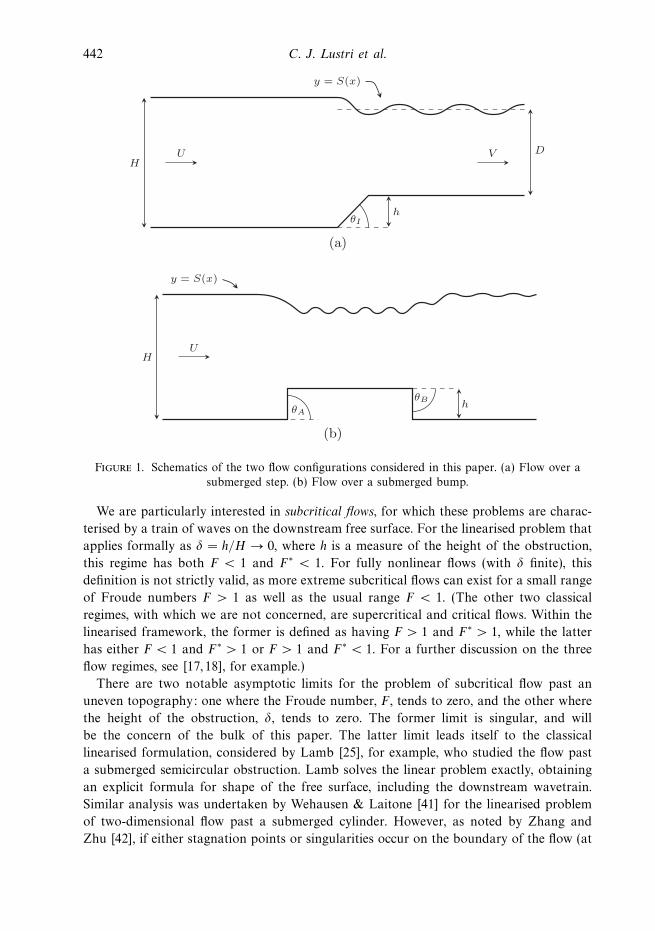
Figure 1. Schematics of the two flow configurations considered in this paper. (a) Flow over asubmerged step. (b) Flow over a submerged bump.
We are particularly interested in subcritical flows, for which these problems are charac-
terised by a train of waves on the downstream free surface. For the linearised problem that
applies formally as ! = h/H $ 0, where h is a measure of the height of the obstruction,
this regime has both F < 1 and F# < 1. For fully nonlinear flows (with ! finite), this
definition is not strictly valid, as more extreme subcritical flows can exist for a small range
of Froude numbers F > 1 as well as the usual range F < 1. (The other two classical
regimes, with which we are not concerned, are supercritical and critical flows. Within the
linearised framework, the former is defined as having F > 1 and F# > 1, while the latter
has either F < 1 and F# > 1 or F > 1 and F# < 1. For a further discussion on the three
flow regimes, see [17, 18], for example.)
There are two notable asymptotic limits for the problem of subcritical flow past an
uneven topography: one where the Froude number, F , tends to zero, and the other where
the height of the obstruction, !, tends to zero. The former limit is singular, and will
be the concern of the bulk of this paper. The latter limit leads itself to the classical
linearised formulation, considered by Lamb [25], for example, who studied the flow past
a submerged semicircular obstruction. Lamb solves the linear problem exactly, obtaining
an explicit formula for shape of the free surface, including the downstream wavetrain.
Similar analysis was undertaken by Wehausen & Laitone [41] for the linearised problem
of two-dimensional flow past a submerged cylinder. However, as noted by Zhang and
Zhu [42], if either stagnation points or singularities occur on the boundary of the flow (at
Free surface flow past topography 443
corners, for example), then for a linear solution to be valid throughout the flow field, the
linearisation must take place in an appropriate conformally mapped plane (as in [18, 22],
for example).
For small Froude numbers F % 1, care must be taken when treating linear problems
valid for ! % 1, since a formal power series in ! breaks down in the limit F $ 0 (the
correction term in the expansion for ! % 1 overtakes the leading order term as F $ 0).
Such issues are addressed by Ogilvie [32] and Dagan [13] for the problem of flow past a
submerged body, and noted more recently by Zhang & Zhu [42] for flow over topography.
As a consequence of this small Froude number nonuniformity, the limits F $ 0 and ! $ 0
do not commute, and provide a distinguished limit that relates both the Froude number
F and the obstruction height !. The absence of commutivity is not unexpected, since
the asymptotic limit F $ 0 is singular, while ! $ 0 is regular. Additionally, numerical
evidence [34, 42] suggests that the amplitude of the surface waves becomes exponentially
small in the limit F $ 0. A formal power series in F2 is therefore unable to capture the
correct surface wave behaviour of the flow in this limit, as the exponentially small waves
take place ‘beyond all orders’ of the power series expansion.
Studies of other two-dimensional free surface problems have demonstrated similar
qualitative results in the limit that the Froude number F $ 0. For example, Vanden-
Broeck and coauthors treat infinite-depth flows both past a two-dimensional stern [38,39]
and due to a submerged line source [38] analytically, and show that for these configurations
a power series in the Froude number squared is everywhere divergent. The finite-depth
versions of these problems are treated in McCue & Forbes [27] and Mekias & Vanden-
Broeck [30], for example, where the main goal was to solve the problems numerically for
all Froude numbers; in these cases, numerical results strongly suggest the amplitude of
the waves is exponentially small in the Froude number as F $ 0. Other early examples of
similar observations are given for flows past submerged bodies and pressure distributions
by Dagan [13] and Doctors & Dagan [15]. Note that these are in contrast to certain
other configurations, such as flow past a semi-infinite plate [2, 26, 28, 29, 31, 37], for which
solutions with downstream waves do not exist for su"ciently small Froude numbers, and
so there is no corresponding small Froude number nonuniformity.
Returning to the subject of free surface flow past a bottom topography, numerical
investigations of these problems normally employ a boundary integral method involving
complex variable theory, sometimes with the use of conformal mappings. In particular,
Forbes & Schwartz [18] treated the flow past a semi-circular obstacle, while King &
Bloor [22] solved for the flow over a step. Further early studies are given by [16,23,42,43],
for example. Of relevance to the present study, Binder et al. [3] recently consider free
surface flow over a bump or trench, such as that sketched in Figure 1(b). For subcritical
flow, they demonstrate that it is possible to obtain a bump/trench configuration for
which the downstream waves past the obstacle are completely eliminated; these are
referred to as trapped-wave solutions. Forbes [16] generated trapped-wave solutions for
free surface flow over a submerged ellipse, while Binder et al. [4] demonstrated that
multiple obstacles on the base of the flow could also be used in order to generate trapped
surface waves between the two separate obstacles. Similar results have been obtained for
obstacles suspended in the flow [19, 36] and for flows past pressure distributions [40], for
example.
444 C. J. Lustri et al.
In response to the analytical and numerical evidence noted above, Chapman & Vanden-
Broeck [12] have recently constructed an asymptotic framework in which two-dimensional
steady free surface flows could be described in the limit F $ 0. These authors employ
techniques in exponential asymptotics, developed in [9,33] (and applied to other potential
flow problems in [7,8]), that involve applying an asymptotic series expansion in powers of
F2 and capturing the precise factorial/power nature of the divergent tail. After truncating
the divergent series optimally, the exponentially small remainder is subsequently analysed
using matched asymptotic expansions, providing an expression for the exponentially small
surface wave behaviour valid in the limit F $ 0. Chapman & Vanden-Broeck [12] apply
this method to the test case of free surface flow over a step, which is illustrated in
Figure 1(a) with "I = !/2. As a result, they demonstrate the existence of a downstream
train of exponentially small surface waves with amplitude of order F&2/5e&c/F2, where c
is a constant related to the height of the step, as F $ 0. These results were subsequently
verified numerically using boundary integral methods. Very recently, Trinh et al. [35]
applied the techniques developed in [12] to the problem of surface-piercing flow past a
semi-infinite stern, resolving many of the issues treated in [38, 39].
In the present study, we revisit the problem of free surface flow over a step, and adapt the
analysis of Chapman & Vanden-Broeck [12] to allow the step to have an arbitrary angle
of inclination, "I , as sketched in Figure 1(a). Mathematically this problem is interesting
since, as pointed out in [12], Stokes lines are generated by corners with in-fluid angles
of greater than 2!/3. Thus for &!/3 < "I < !/3 there are, in general, exponentially
small correction terms generated from two active Stokes lines, whereas in the case treated
in detail in [12] (that is, "I = !/2), there is only one such Stokes line. As a result, for
&!/3 < "I < !/3 there are two points on the free surface at which exponentially small
waves are ‘switched on’. We find that one of the wavetrains has an amplitude of order
F&2(3"I&!)/(3"I+!)e&c/F2as the Froude number F $ 0, while the other has an amplitude
of order F&2(3"I+!)/(3"I&!)e&1/F2. Downstream, one of these contributions is exponentially
subdominant compared to the other (meaning that the smaller of the contributions will
be almost impossible to detect in practice); however, for 0 < "I < !/3, there is a finite
region, between the points at which the two active Stokes lines intersect the free surface,
over which only the smaller of the two contributions is present, leading to an intermediate
wavetrain not previously noted for this type of problem. Furthermore, we find that for an
infinite number of angles in the range &!/3 < "I < !/3, the amplitude of the subdominant
wavetrain vanishes, leaving only the contribution of a single active Stokes line.
To extend these ideas further, we apply the techniques to the problem of flow over a
submerged bump or trench, allowing for inclined sides, as in Figure 1(b). In this case
there may be two, three or four active Stokes lines, depending on the angles "A and
"B . We find that it is possible to construct the base topography in such a manner that
the wave contributions from separate Stokes lines are of equal magnitude, but directly
out of phase. As a result, we are able to generate trapped-wave solutions for particular
base configurations, supporting the complementary results for the limit that the Froude
number F $ 1& (with small obstacle height, ! % 1) by Binder et al. [3] using weakly
nonlinear theory.
The layout of the paper is as follows. We begin in Section 2 by formulating the
problem of flow over an inclined step using conformal mapping techniques. Subsequently,
Free surface flow past topography 445
in Section 3 we follow the general method outlined by Chapman & Vanden-Broeck [12]
for the specific case of flow over an inclined step in order to obtain the exponentially
small contribution to the surface behaviour as F $ 0. In Section 4, we present results
for this problem and note the possible existence of multiple downstream wavetrains due
to the presence of multiple singularities in the flow path. Numerical solutions to the
full nonlinear problem are presented to support our findings. The results obtained in
Sections 3 and 4 are extended in Section 5 for flow over a submerged bump or trench,
particularly noting the possibility of trapped-wave free surface solutions, while the paper
concludes in Section 6 with a brief discussion.
2 Formulation for flow over an inclined step
2.1 Governing equations in physical plane
We consider irrotational flow of an incompressible fluid over an inclined step of height
h, with the upstream speed given by U, and the upstream channel depth given by H (see
Figure 1(a)). We denote the velocity of the fluid as q(x, y), where q = q cos " i + q sin " j,
where q = |q| is the speed of the flow, and " gives the angle between the streamline and
the horizontal at a given point. As the flow is irrotational, we write q = !#, where # is the
velocity potential. Together with incompressibility ! · q = 0, we have Laplace’s equation
'2# = 0 (2.1)
throughout the flow domain, except at singular points on the boundary.
We scale all velocities by a factor of U and the lengths by a factor of H/!, and
use dimensionless equations from here on. The scaled equivalent of the topography in
Figure 1(a) is shown in Figure 2(a). In terms of the velocity potential, the problem is now
to solve (2.1) subject to
!# · n = 0 (2.2)
on the solid bottom boundary below and the free surface y = S(x) above, where n is a
normal vector to these surfaces. Far upstream we have # ( x as x $ &). Finally, we
have Bernoulli’s equation
1
2q2 +
y
!F2=
1
2+
1
F2on y = S(x), (2.3)
where F is the upstream Froude number defined in (1.1). To be consistent with Chapman
& Vanden-Broeck [12] we shall introduce the parameter $ = !F2, but of course the
subsequent analysis could as well be applied using F2 as the small parameter.
2.2 Conformal mapping
As is well known, since the velocity potential # satisfies (2.1), the complex potential
w(z) = # + i% is an analytic function of the complex variable z = x + iy (except at
singular points), where % is the streamfunction that also satisfies Laplace’s equation. We
are free to set % = 0 on the free surface y = S(x), and it therefore follows that % = &!
446 C. J. Lustri et al.
A B
C
D
EF
!I
1"
h
x
y
(a) z-plane.
#
$
CBA D
EF
# = !"
# = 0
(b) w-plane
%
&
A B C
& = !1& = !b
DE F
(c) !-plane.
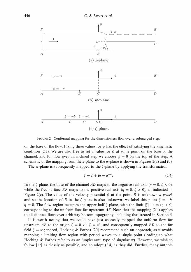
Figure 2. Conformal mapping for the dimensionless flow over a submerged step.
on the base of the flow. Fixing these values for % has the e!ect of satisfying the kinematic
condition (2.2). We are also free to set a value for # at some point on the base of the
channel, and for flow over an inclined step we choose # = 0 on the top of the step. A
schematic of the mapping from the z-plane to the w-plane is shown in Figures 2(a) and (b).
The w-plane is subsequently mapped to the &-plane by applying the transformation
& = ' + i( = e&w. (2.4)
In the &-plane, the base of the channel AD maps to the negative real axis (( = 0, ' < 0),
while the free surface EF maps to the positive real axis (( = 0, ' > 0), as indicated in
Figure 2(c). The value of the velocity potential # at the point B is unknown a priori,
and so the location of B in the &-plane is also unknown; we label this point ' = &b,
( = 0. The flow region occupies the upper-half &-plane, with the limit |&| $ ) (( > 0)
corresponding to the uniform flow far upstream AF . Note that the mapping (2.4) applies
to all channel flows over arbitrary bottom topography, including that treated in Section 5.
It is worth noting that we could have just as easily mapped the uniform flow far
upstream AF to the origin & = 0 via & = ew , and consequently mapped ED to the far
field & = ); indeed, Hocking & Forbes [20] recommend such an approach, as it avoids
mapping a limiting flow region with period waves to a single point (leading to what
Hocking & Forbes refer to as an ‘unpleasant’ type of singularity). However, we wish to
follow [12] as closely as possible, and so adopt (2.4) as they did. Further, many authors
Free surface flow past topography 447
apply conformal transformations that map periodic waves to a single point for flow over
uneven topography, apparently with considerable success (see [3, 22, 43], for example).
2.3 Boundary integral approach
The complex velocity dw/dz = qe&i" is an analytic function of z and, as such, ln q & i" is
an analytic function of &. We derive an integral equation by applying Cauchy’s integral
formula to ln q&i", taking the contour to be the part of the real axis &R < ' < R together
with a semi-circle centred at & = 0 with radius R. In the limit R $ ), the imaginary part
gives
ln q = & 1
!&! )
&)
"('*)
'* & 'd'*, (2.5)
where here q(') and "(') are real quantities on the boundary of the flow domain. The
integral in (2.5) is of Cauchy Principal Value type.
For flow over an inclined step, as depicted in Figure 2, the function "(') for ' < 0
describes the angle of the bottom topography. Since the sloped face of the step maps to
&b ! ' < &1, we have as an input to the problem
"(') =
"#
$
0 ' < &b,
"I &b ! ' < &1,
0 &1 ! ' < 0,
(2.6)
and thus (2.5) simplifies to
ln q ="I!
ln
%' + b
' + 1
&& 1
!&! )
0
"('*)
'* & 'd'*, ' > 0. (2.7)
Equation (2.7) provides one equation relating q and " on the free surface ' > 0. It is
worth emphasising that solutions to (2.7) identically satisfy Laplace’s equation (2.1) and
the kinematic condition (2.2).
To close the system we first note that di!erentiating & = e&w with respect to z gives the
inverse transform
dx
d'= & 1
'qcos ",
dy
d'= & 1
'qsin ", ' > 0. (2.8)
Thus di!erentiating Bernoulli’s equation (2.3) with respect to ' leads to
$q2'dq
d'= sin ", ' > 0 (2.9)
(remembering that we are using the parameter $ = !F2, where F is the Froude number).
The problem of steady free surface flow over an inclined step therefore consists of the
coupled system (2.7) and (2.9) for the unknown functions q(') and "(') on the free surface
' > 0, ( = 0. The problem has three parameters: $, which is e!ectively the Froude number
squared; the step angle "I ; and b > 0, which is a measure of the step height. Given the
speed q and angle ", the shape of the free surface in the physical plane is recovered via
448 C. J. Lustri et al.
(2.8). Finally, the physical step height h can be found from conservation of mass
limx$)
%(x, h) = &! !
h
q(0) dy,
which gives
h = !
%1 & 1
q(0)
&. (2.10)
We emphasise that (2.5) and (2.8)–(2.9) hold for more general flows past a bottom
topography, including flow over a bump or trench with inclined sides, as treated in
Section 5. The defining characteristics of each flow geometry are provided by the angles
of each segment on the bottom, as in (2.6). Thus the first term on the right-hand side of
(2.7) is for flow over an inclined step; for other flows this term will change.
2.4 Complexifying the free surface
The two real-valued equations (2.7) and (2.9) hold only on the free surface ' > 0, ( = 0.
A series expansion for q(') and "(') in powers of $ diverges, this divergence being caused
by the presence of singularities in the analytic extension of q(') and "(') into the complex
'-plane which (abusing notation somewhat) we refer to as the &-plane. Thus, in order to
proceed, we analytically continue (2.7) and (2.9) into the upper half &-plane, giving
log q & i" ="I!
log
%& + b
& + 1
&& 1
!
! )
0
"('*)
'* & &d'*, (2.11)
$q2&dq
d&= sin ". (2.12)
The functions q(&) and "(&) that satisfy (2.11)–(2.12) e!ectively provide a complexified
description of the free surface. It will be at the singularities of q(&) and "(&) that Stokes
lines originate (these will be at & = &1 and/or & = &b, depending on the angle "I ) and
across the Stokes lines that the exponentially small surface waves will be ‘switched on’.
Thus, it is important to treat (2.11)–(2.12) in what follows, instead of the real-valued
equations (2.7) and (2.9) (but we note, of course, that (2.11)–(2.12) reduce to (2.7) and
(2.9) on the positive '-axis).
3 Exponential asymptotics
3.1 Preamble
In order to determine the form of the waves on the free surface, we solve (2.11) and (2.12)
asymptotically as $ $ 0. We will apply the method developed in [9, 12], which involves
analysing the form of the late-order terms of the (divergent) series expansion (in powers of
$; see (3.1) below) and truncating the series optimally. The error after optimal truncation
will be exponentially small in $. The idea is to determine how this exponentially small
correction term ‘switches on’ across Stokes lines, and also to calculate where the Stokes
lines intersect the free surface. The waves will appear on the surface downstream from
this intersection point.
Free surface flow past topography 449
The theory in this section is essentially taken from [12], with the emphasis on the
problem of flow over an inclined step (the main ideas carry over to the problem of flow
over a bump or trench, treated in Section 5, except that instead of having the important
singularities located at & = &1 or &b, they are at & = &d, &c, &b and &a). The new
results for flow over an inclined step are provided in Section 4.
3.2 Asymptotic power series expansion
We express the components of the fluid velocity as power series in $:
" ()'
n=0
$n"n, q ()'
n=0
$nqn as $ $ 0. (3.1)
Thus, from (2.11) and (2.12), we have
$& (q0 + $q1 + . . .)2d
d&(q0 + $q1 + . . .) = "0 + $"1 + . . . , (3.2)
log q0 + $q1
q0+ . . .&i ("0 + $"1 + . . .) =
"I!
log
%& + b
& + 1
&
& 1
!
! )
0
"0('*) + $"1('*) + . . .
'* & &d'* , (3.3)
where the omitted terms are O($2) or smaller. To leading order we find "0 + 0, with the
first nonzero terms for q and " being
q0 =
%& + b
& + 1
&"I /!
, (3.4)
"1 = &"I!
&(b & 1)
(& + 1)(& + b)
%& + b
& + 1
&3"I /!
. (3.5)
Obtaining expressions for the higher-order terms quickly becomes di"cult, and in any
event is not necessary. A crucial point to note is that the terms "0('), q0(') and "1(')
do not oscillate on the free surface ' > 0, and so cannot describe wavelike behaviour.
Furthermore, since these lower-order terms are waveless, the higher order terms will be
as well. The reason that straightforward power series expansion (3.1) does not capture
the waves is that the wave amplitude is exponentially small compared to all the terms
in (3.1). Thus, the wave behaviour lies ‘beyond all orders’ of the asymptotic power series
expansion.
3.3 Late-order terms
In order to truncate (3.1) optimally, we must determine from (3.2)–(3.3) the form of qn,
"n as n $ ). Following [12], and keeping only terms that will be dominant as n $ ), we
find
q20&
dqn&1
d&+ 2q0q1&
dqn&2
d&+ · · · + 2q0qn&1&
dq0
d&+ . . . = "n + . . . , (3.6)
450 C. J. Lustri et al.
qnq0
& qn&1q1
q0+ · · · & i"n = & 1
!
! )
0
"n('*) d'*
'* & &, n " 3. (3.7)
As a means to motivate an appropriate ansatz for qn and "n in the upper &-plane (provided
in (3.10) below), we note from (3.4) that near & = &1 and & = &b,
q0 ( )(& & &0)* as & $ &0,
where
* = &"I!, ) = (b & 1)"I /!, for &0 = &1, (3.8)
* ="I!, ) = (1 & b)&"I /!, for &0 = &b. (3.9)
Using (3.6)–(3.7), we are able to obtain the behaviour of each term in the neighbourhood
of either & = &1 or &b, noting that the integral on the right-hand side of (3.7) is
subdominant when compared to the left-hand side in the limit that & $ &1 or &b,
significantly simplifying the expression. We find that
qn ( in+2*µn)3n+1(& & &0)
n(3*&1)+*, "n ( in+1*+n)3n(& & &0)
n(3*&1), (3.10)
in the neighbourhood of &0 as n $ ), where * and ) depend on whether &0 is &1
or &b (through (3.8)–(3.9)), and µn and +n are polynomials in * of order n & 1 with a
constant term (n & 1)!. Thus, in the neighbourhood of & = &1 the late order terms grow
in the familiar factorial/power rate when "I > &!/3 (forcing 3* & 1 < 0), while in the
neighbourhood of & = &b we encounter the same type of divergence when "I < !/3
(again forcing 3* & 1 < 0). It follows that for "I > !/3 there is only one singularity (at
& = &1), including the special case "I = !/2 considered in detail by [12]. Similarly, for
"I < &!/3 there is also one singularity (this time at & = &b), which includes the case
"I = &!/2 for a step down mentioned in [12]. Interestingly, for &!/3 < "I < !/3 the late
order terms diverge near both & = &1 and & = &b, meaning for this range of step angles
there will be two Stokes lines of interest (originating at each of & = &1 and & = &b),
across which waves will be switched on. In general, one of these contributions will be
subdominant, meaning that in practice it will not be observed; however, there will be a
region on the free surface over which only the subdominant wave train appears (we shall
call this an intermediate wavetrain).
While the above argument does not apply away from the singularities at & = &1
or b, the asymptotic expansion (3.1) still diverges for any fixed &. To obtain the form
of the late-order terms qn and "n in the entirety of the upper &-plane, Chapman &
Vanden-Broeck [12] apply the ansatz
"n ( ,- (n + .)
/n+., qn ( Q- (n + .)
/n+.(3.11)
as n $ ), where / is forced to be zero at & = &0, with &0 = &1 or &b. (For the range
&!/3 < "I < !/3, where both singularities exist, the idea is to write "n and qn as a sum of
two terms of the form (3.11), with one having / = 0 at & = &1 and the other with / = 0
Free surface flow past topography 451
at & = &b.) By substituting (3.11) into (3.6)-(3.7), Chapman & Vanden-Broeck find that
/ = i
! &
&0
d& *
& *q30
, (3.12)
, = & 0
q30
exp
%3i
! &
0
q1
& *q40
d& *&, Q =
0
q20
exp
%3i
! &
0
q1
& *q40
d& *&. (3.13)
To obtain these results we must assume the integral on the right-hand side of (3.7) is
subdominant as n $ ). Arguments in support of this assumption are given recently in
Trinh et al. [35], and the references therein.
The constants . and 0 are found by matching (3.11)–(3.13) with (3.10) near the
appropriate singularities & = &1 or &b, with the result that
. = & 6*
1 & 3*, 0 =
)6&3.ei!./2
2C(1 & 3*).limn$)
1n
- (n + .), (3.14)
where * is related to "I through (3.8)–(3.9) (depending on which singularity is appropriate),
C = q30(0) exp
%&3i
! &
0
1
&!q30
! )
&)
"1('*)d'*
'* & 'd&
&
and 1n is given by
10 = 1, 1n =n&1'
m=0
%m & 2*
1 & 3*
&1m1n&m&1.
For full details, see [12].
Finally, from Dingle [14], we know that Stokes lines will follow the contour where
the successive late-order terms "n and qn have the same phase, which is given by
the curve where / is real and positive. As such, by determining the form of the late-
order terms, we have obtained an expression for the path followed by the Stokes line
originating from the singularity at & = &0, where &0 = &1 or &b. This is significant, as a
downstream wavetrain will be switched on at the point where this Stokes line intersects
with the free surface. (To be precise, the local condition 3*&1 < 0 guarantees a singularity
and thus Stokes lines, but the question of whether the Stokes line encounters the free
surface is a global issue and depends on the behaviour of q0 in the complex plane. For
the examples treated in this paper the Stokes lines do intersect the free surface.)
3.4 Behaviour in the neighbourhood of Stokes lines
With the form of the late-order terms for q and " now identified, we truncate (3.1) after
N terms and write
" =N&1'
n=0
$n"n + RN, q =N&1'
n=0
$nqn + SN, (3.15)
where RN and SN are the remainder terms. As mentioned above, behaviour that is
exponentially small in $ as $ $ 0 cannot be demonstrated by the series in (3.15); however,
452 C. J. Lustri et al.
it is well known that such behaviour is described by RN and SN when (3.1) is truncated
optimally [1]. The following analysis that shows how the exponentially small wavetrain is
made visible is essentially a summary of [12], but with some emphasis on our particular
application (by keeping q0 and q1 unspecified, the details apply for flows over a more
general topology).
By substituting (3.15) into (3.6)–(3.7), we derive a first order di!erential equation for SNin the limit N $ ) and $ $ 0. The homogeneous version of this equation has a solution
Qe&//$, where / and Q are given by (3.12)–(3.13) (this homogeneous solution is consistent
with the ansatz (3.11) for the late order terms), motivating the form
SN = AQ e&//$,
where the unknown function A(&; $) is the Stokes multiplier. Optimal truncation gives
N ( |/|/$ as $ $ 0, which then provides a di!erential equation for A in terms of / and $.
By writing / = 2ei3 (here 3 is not to be confused with the dependent variable "), matched
asymptotic expansions yields
A =
"2!i
$.
! "23/$
&)e&t2/2dt, (3.16)
with A clearly varying smoothly and rapidly in the neighbourhood of the point where
the Stokes line intersects the free surface, given as 3 = 0. Finally, matching away from
the Stokes line allows us to show that the jump in A across the Stokes line is 2!i/$. . The
information regarding the remainder RN is then determined via RN ( &iSN/q0 as N $ ).
We find that the exponentially small correction terms that are smoothly switched on by
the appropriate singularity (either & = &1 or &b) take the form
2!i
$.,e&//$,
2!i
$.Qe&//$, (3.17)
respectively, as $ $ 0.
For the above, we have analytically continued (2.7) and (2.9) into the upper half &-plane,
but an analogous analysis holds if we were to analytically continue into the lower half
plane, except that the contribution that switches on as the Stokes line is crossed is the
complex conjugate of the terms in (3.17). Taking this contribution into account, and using
the notation "exp to denote the leading order term for the remainder on the free surface
& = ', we have
"exp = 2|A,|e&Re(/)/$ cos
%arg, & Im(/)
$
&
=2|A0|q3
0
e&Re(/)/$ cos
%3
! '
0
q1
'*q40
d'* + arg0 & Im(/)
$
&. (3.18)
This expression is clearly oscillatory, and as such demonstrates the existence of the
exponentially small free surface waves under investigation. To help compute the term |0|
Free surface flow past topography 453
!I
(a) "I > !3
!I
(b) 0 < "I < !3
!I
(c) !!3 < "I < 0. .
..
!I
(d) "I < !!3
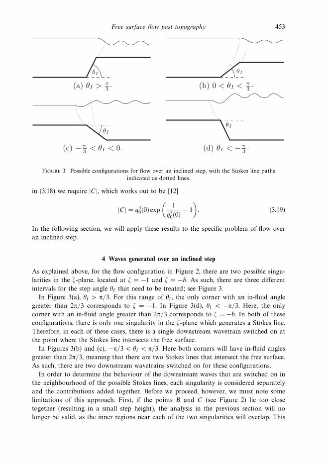
Figure 3. Possible configurations for flow over an inclined step, with the Stokes line pathsindicated as dotted lines.
in (3.18) we require |C|, which works out to be [12]
|C| = q30(0) exp
%1
q30(0)
& 1
&. (3.19)
In the following section, we will apply these results to the specific problem of flow over
an inclined step.
4 Waves generated over an inclined step
As explained above, for the flow configuration in Figure 2, there are two possible singu-
larities in the &-plane, located at & = &1 and & = &b. As such, there are three di!erent
intervals for the step angle "I that need to be treated; see Figure 3.
In Figure 3(a), "I > !/3. For this range of "I , the only corner with an in-fluid angle
greater than 2!/3 corresponds to & = &1. In Figure 3(d), "I < &!/3. Here, the only
corner with an in-fluid angle greater than 2!/3 corresponds to & = &b. In both of these
configurations, there is only one singularity in the &-plane which generates a Stokes line.
Therefore, in each of these cases, there is a single downstream wavetrain switched on at
the point where the Stokes line intersects the free surface.
In Figures 3(b) and (c), &!/3 < "I < !/3. Here both corners will have in-fluid angles
greater than 2!/3, meaning that there are two Stokes lines that intersect the free surface.
As such, there are two downstream wavetrains switched on for these configurations.
In order to determine the behaviour of the downstream waves that are switched on in
the neighbourhood of the possible Stokes lines, each singularity is considered separately
and the contributions added together. Before we proceed, however, we must note some
limitations of this approach. First, if the points B and C (see Figure 2) lie too close
together (resulting in a small step height), the analysis in the previous section will no
longer be valid, as the inner regions near each of the two singularities will overlap. This
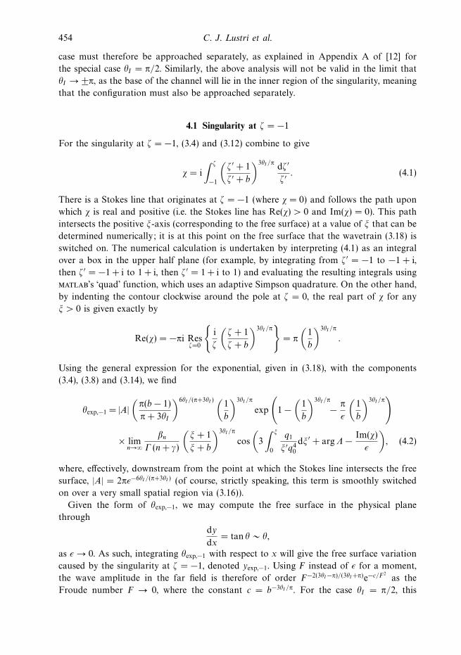
454 C. J. Lustri et al.
case must therefore be approached separately, as explained in Appendix A of [12] for
the special case "I = !/2. Similarly, the above analysis will not be valid in the limit that
"I $ ±!, as the base of the channel will lie in the inner region of the singularity, meaning
that the configuration must also be approached separately.
4.1 Singularity at & = &1
For the singularity at & = &1, (3.4) and (3.12) combine to give
/ = i
! &
&1
%& * + 1
& * + b
&3"I /! d& *
& * . (4.1)
There is a Stokes line that originates at & = &1 (where / = 0) and follows the path upon
which / is real and positive (i.e. the Stokes line has Re(/) > 0 and Im(/) = 0). This path
intersects the positive '-axis (corresponding to the free surface) at a value of ' that can be
determined numerically; it is at this point on the free surface that the wavetrain (3.18) is
switched on. The numerical calculation is undertaken by interpreting (4.1) as an integral
over a box in the upper half plane (for example, by integrating from & * = &1 to &1 + i,
then & * = &1 + i to 1 + i, then & * = 1 + i to 1) and evaluating the resulting integrals using
matlab’s ‘quad’ function, which uses an adaptive Simpson quadrature. On the other hand,
by indenting the contour clockwise around the pole at & = 0, the real part of / for any
' > 0 is given exactly by
Re(/) = &!i Res&=0
(i
&
%& + 1
& + b
&3"I /!)
= !
%1
b
&3"I /!
.
Using the general expression for the exponential, given in (3.18), with the components
(3.4), (3.8) and (3.14), we find
"exp,&1 = |A|%
!(b & 1)
! + 3"I
&6"I /(!+3"I ) %1
b
&3"I /!
exp
*1 &
%1
b
&3"I /!
& !
$
%1
b
&3"I /!+
, limn$)
1n
- (n + .)
%' + 1
' + b
&3"I /!
cos
%3
! '
0
q1
'*q40
d'* + arg0 & Im(/)
$
&, (4.2)
where, e!ectively, downstream from the point at which the Stokes line intersects the free
surface, |A| = 2!$&6"I /(!+3"I ) (of course, strictly speaking, this term is smoothly switched
on over a very small spatial region via (3.16)).
Given the form of "exp,&1, we may compute the free surface in the physical plane
through
dy
dx= tan " ( ",
as $ $ 0. As such, integrating "exp,&1 with respect to x will give the free surface variation
caused by the singularity at & = &1, denoted yexp,&1. Using F instead of $ for a moment,
the wave amplitude in the far field is therefore of order F&2(3"I&!)/(3"I+!)e&c/F2as the
Froude number F $ 0, where the constant c = b&3"I /!. For the case "I = !/2, this

Free surface flow past topography 455
result agrees with that given in Chapman & Vanden-Broeck [12] (and mentioned in the
Introduction).
4.2 Singularity at & = &b
A similar analysis holds for the singularity at & = &b. In this case the form of / changes
slightly to give
/ = i
! &
&b
%& * + 1
& * + b
&3"I /! d& *
& * . (4.3)
Again, the Stokes line originates at & = &b and intersects the '-axis at some finite value
of '; it is at this point that the wavetrain (3.18) is switched on. Now suppose that & is
real and positive in (4.3). By integrating from & * = &b to & * = ' > 0 via a contour that
runs from & * = &b to & * = &), clockwise around an infinitely large semi-circle, and then
from & * = ) to & * = ', we find that
Re(/) = !.
Thus, combining (3.4), (3.9), (3.14) and (3.18), we have
"exp,&b = |A|%
! & 3"I!(1 & b)
&6"I /(!&3"I ) %1
b
&3"I /!
exp
*1 &
%1
b
&3"I /!
& !
$
+
, limn$)
1n
- (n + .)
%' + 1
' + b
&3"I /!
cos
%3
! '
0
q1
'*q40
d'* + arg0 & Im(/)
$
&. (4.4)
In cases, in which (1 & b)6"I /(!&3"I ) is complex, we must take care to include an additional
argument in the cosine term. Again, integrating "exp,&b with respect to x will give the
free surface amplitude, yexp,&b. In this case we find the wave amplitude is of order
F&2(3"I+!)/(3"I&!)e&1/F2as the Froude number F $ 0.
4.3 Flow over an inclined step with one Stokes line
We consider the flow configurations shown in Figures 3(a) and (d). In both of these
configurations, there is only one corner with an in-fluid angle greater than 2!/3, and
thus only one Stokes line in the &-plane originating at the associated singularity. In (a),
this corner corresponds to a singularity at & = &1. The Stokes line generated at this
singularity will follow the path upon which /, given in (4.1), is real and positive. At the
point where this Stokes line intersects the free surface, exponentially small variation in ",
given in (4.2), will be switched on. In (d), however, it is the first corner in the flow path
which has an in-fluid angle greater than 2!/3. This angle corresponds to a singularity at
& = &b, which will generate a Stokes line that follows the curve along which /, given in
(4.3), is real and positive. At the point where this Stokes line intersects the free surface,
exponentially small variation in ", given in (4.4), will be switched on.
Figure 4 shows approximate free surface plots for flow over an inclined step, obtained
by computing the early terms "0 + $"1 of the asymptotic expansion (3.1) (or, equivalently,
(3.15)) for the position of the free surface, and adding the exponentially small free surface
456 C. J. Lustri et al.
x!5 5 100
!0.1
!0.2
y
(a) "I = !2 (solid), "I = 3!
8 (grey).
x
y
!5 5 100
0.05
0.1
(b) "I = !!2 (solid), "I = ! 3!
8 (grey).
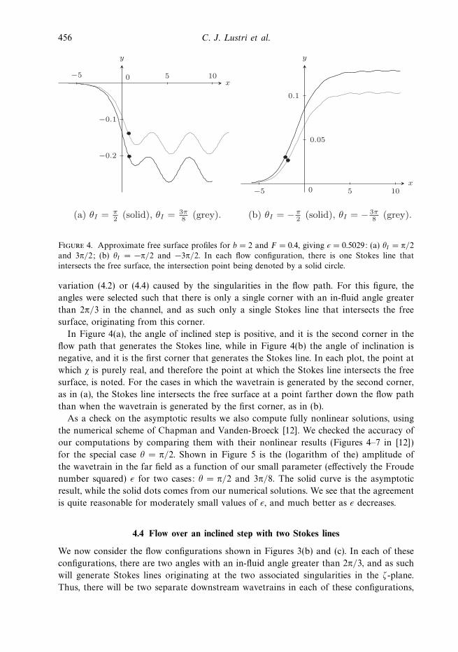
Figure 4. Approximate free surface profiles for b = 2 and F = 0.4, giving $ = 0.5029: (a) "I = !/2and 3!/2; (b) "I = &!/2 and &3!/2. In each flow configuration, there is one Stokes line thatintersects the free surface, the intersection point being denoted by a solid circle.
variation (4.2) or (4.4) caused by the singularities in the flow path. For this figure, the
angles were selected such that there is only a single corner with an in-fluid angle greater
than 2!/3 in the channel, and as such only a single Stokes line that intersects the free
surface, originating from this corner.
In Figure 4(a), the angle of inclined step is positive, and it is the second corner in the
flow path that generates the Stokes line, while in Figure 4(b) the angle of inclination is
negative, and it is the first corner that generates the Stokes line. In each plot, the point at
which / is purely real, and therefore the point at which the Stokes line intersects the free
surface, is noted. For the cases in which the wavetrain is generated by the second corner,
as in (a), the Stokes line intersects the free surface at a point farther down the flow path
than when the wavetrain is generated by the first corner, as in (b).
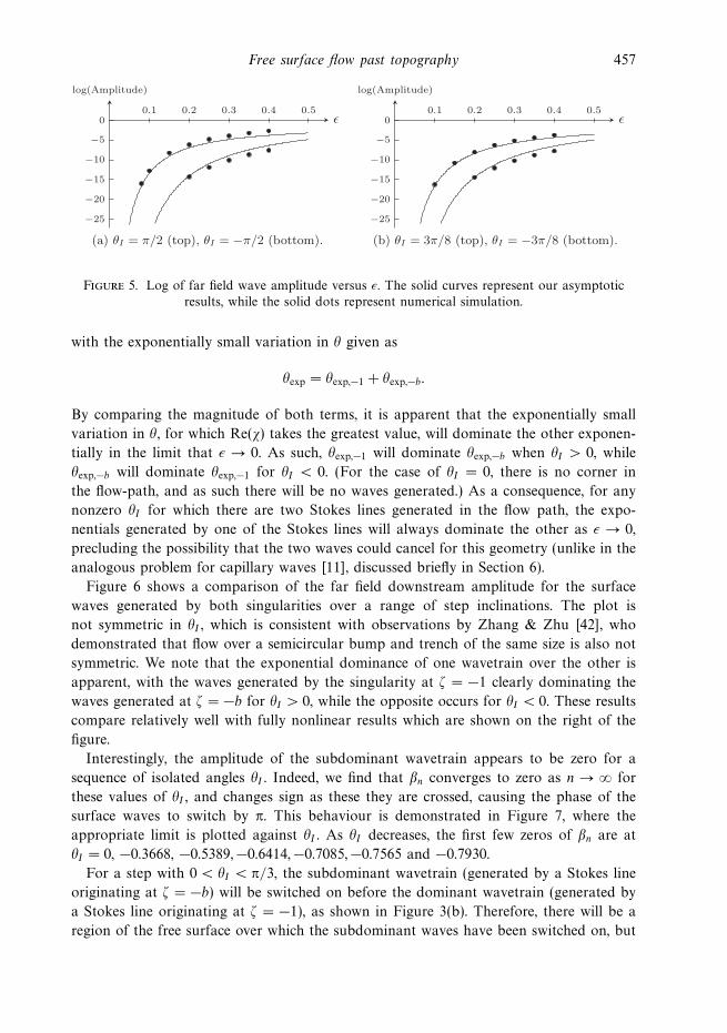
As a check on the asymptotic results we also compute fully nonlinear solutions, using
the numerical scheme of Chapman and Vanden-Broeck [12]. We checked the accuracy of
our computations by comparing them with their nonlinear results (Figures 4–7 in [12])
for the special case " = !/2. Shown in Figure 5 is the (logarithm of the) amplitude of
the wavetrain in the far field as a function of our small parameter (e!ectively the Froude
number squared) $ for two cases: " = !/2 and 3!/8. The solid curve is the asymptotic
result, while the solid dots comes from our numerical solutions. We see that the agreement
is quite reasonable for moderately small values of $, and much better as $ decreases.
4.4 Flow over an inclined step with two Stokes lines
We now consider the flow configurations shown in Figures 3(b) and (c). In each of these
configurations, there are two angles with an in-fluid angle greater than 2!/3, and as such
will generate Stokes lines originating at the two associated singularities in the &-plane.
Thus, there will be two separate downstream wavetrains in each of these configurations,
Free surface flow past topography 457
log(Amplitude)
0
!5
!10
!15
!20
!25
0.1 0.2 0.3 0.4 0.5
(a) "I = #/2 (top), "I = !#/2 (bottom).
log(Amplitude)
0
!5
!10
!15
!20
!25
0.1 0.2 0.3 0.4 0.5
(b) "I = 3#/8 (top), "I = !3#/8 (bottom).
Figure 5. Log of far field wave amplitude versus $. The solid curves represent our asymptoticresults, while the solid dots represent numerical simulation.
with the exponentially small variation in " given as
"exp = "exp,&1 + "exp,&b.
By comparing the magnitude of both terms, it is apparent that the exponentially small
variation in ", for which Re(/) takes the greatest value, will dominate the other exponen-
tially in the limit that $ $ 0. As such, "exp,&1 will dominate "exp,&b when "I > 0, while
"exp,&b will dominate "exp,&1 for "I < 0. (For the case of "I = 0, there is no corner in
the flow-path, and as such there will be no waves generated.) As a consequence, for any
nonzero "I for which there are two Stokes lines generated in the flow path, the expo-
nentials generated by one of the Stokes lines will always dominate the other as $ $ 0,
precluding the possibility that the two waves could cancel for this geometry (unlike in the
analogous problem for capillary waves [11], discussed briefly in Section 6).
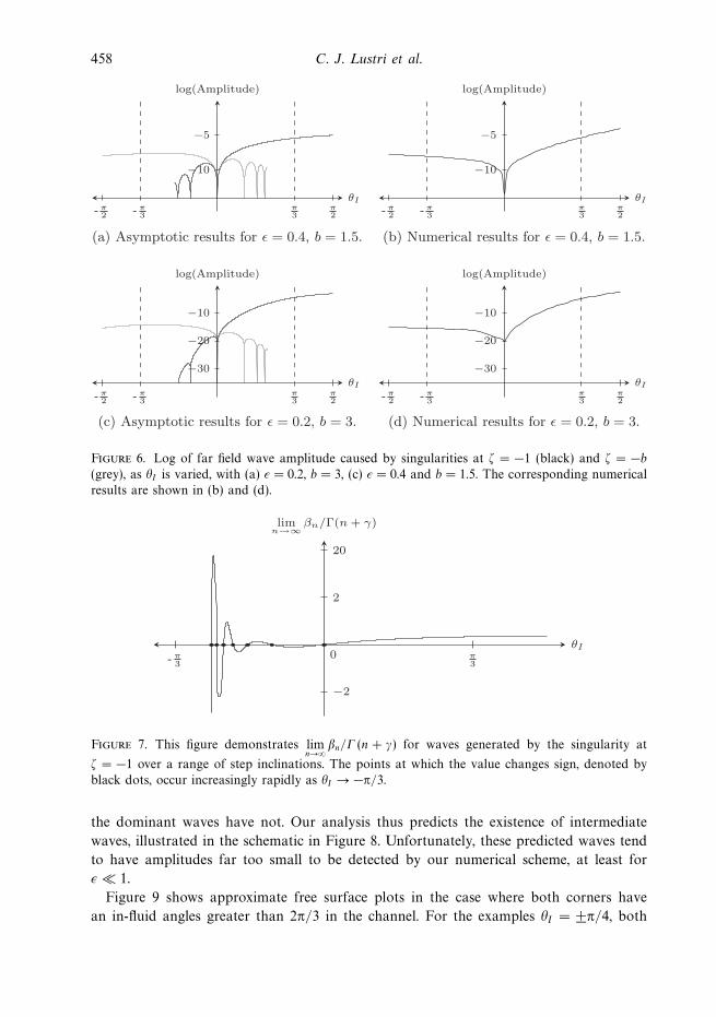
Figure 6 shows a comparison of the far field downstream amplitude for the surface
waves generated by both singularities over a range of step inclinations. The plot is
not symmetric in "I , which is consistent with observations by Zhang & Zhu [42], who
demonstrated that flow over a semicircular bump and trench of the same size is also not
symmetric. We note that the exponential dominance of one wavetrain over the other is
apparent, with the waves generated by the singularity at & = &1 clearly dominating the
waves generated at & = &b for "I > 0, while the opposite occurs for "I < 0. These results
compare relatively well with fully nonlinear results which are shown on the right of the
figure.
Interestingly, the amplitude of the subdominant wavetrain appears to be zero for a
sequence of isolated angles "I . Indeed, we find that 1n converges to zero as n $ ) for
these values of "I , and changes sign as these they are crossed, causing the phase of the
surface waves to switch by !. This behaviour is demonstrated in Figure 7, where the
appropriate limit is plotted against "I . As "I decreases, the first few zeros of 1n are at
"I = 0, &0.3668, &0.5389,&0.6414,&0.7085,&0.7565 and &0.7930.
For a step with 0 < "I < !/3, the subdominant wavetrain (generated by a Stokes line
originating at & = &b) will be switched on before the dominant wavetrain (generated by
a Stokes line originating at & = &1), as shown in Figure 3(b). Therefore, there will be a
region of the free surface over which the subdominant waves have been switched on, but
458 C. J. Lustri et al.
!I
log(Amplitude)
!3- !
3!2- !
2
!10
!5
(a) Asymptotic results for = 0.4, b = 1.5.
!I
log(Amplitude)
!10
!5
(b) Numerical results for = 0.4, b = 1.5.
!I
log(Amplitude)
!10
!20
!30
(c) Asymptotic results for = 0.2, b = 3.
!I
log(Amplitude)
!10
!20
!30
(d) Numerical results for = 0.2, b = 3.
- !3- !
2!3
!2
!3- !
3!2- !
2 - !3- !
2!3
!2
Figure 6. Log of far field wave amplitude caused by singularities at & = &1 (black) and & = &b(grey), as "I is varied, with (a) $ = 0.2, b = 3, (c) $ = 0.4 and b = 1.5. The corresponding numericalresults are shown in (b) and (d).
!I
limn!"
'n/!(n + ()
0 !3-
2
20
!2
!3
Figure 7. This figure demonstrates limn$)
1n/- (n + .) for waves generated by the singularity at
& = &1 over a range of step inclinations. The points at which the value changes sign, denoted byblack dots, occur increasingly rapidly as "I $ &!/3.
the dominant waves have not. Our analysis thus predicts the existence of intermediate
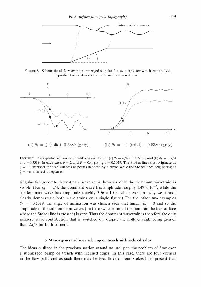
waves, illustrated in the schematic in Figure 8. Unfortunately, these predicted waves tend
to have amplitudes far too small to be detected by our numerical scheme, at least for
$ % 1.
Figure 9 shows approximate free surface plots in the case where both corners have
an in-fluid angles greater than 2!/3 in the channel. For the examples "I = ±!/4, both
Free surface flow past topography 459
!I
intermediate waves
Figure 8. Schematic of flow over a submerged step for 0 < "I < !/3, for which our analysispredict the existence of an intermediate wavetrain.
x!5 5 100
!0.05
!0.1
y
(a) "I = !4 (solid), 0.5389 (grey).
x
y
!5 5 100
0.05
(b) "I = ! (solid), !0.5389 (grey).!4
Figure 9. Asymptotic free surface profiles calculated for (a) "I = !/4 and 0.5389, and (b) "I = &!/4and &0.5389. In each case, b = 2 and F = 0.4, giving $ = 0.5029. The Stokes lines that originate at& = &1 intersect the free surfaces at points denoted by a circle, while the Stokes lines originating at& = &b intersect at squares.
singularities generate downstream wavetrains, however only the dominant wavetrain is
visible. (For "I = !/4, the dominant wave has amplitude roughly 1.49 , 10&2, while the
subdominant wave has amplitude roughly 3.56 , 10&7, which explains why we cannot
clearly demonstrate both wave trains on a single figure.) For the other two examples
"I = ±0.5389, the angle of inclination was chosen such that limn$) 1n = 0 and so the
amplitude of the subdominant waves (that are switched on at the point on the free surface
where the Stokes line is crossed) is zero. Thus the dominant wavetrain is therefore the only
nonzero wave contribution that is switched on, despite the in-fluid angle being greater
than 2!/3 for both corners.
5 Waves generated over a bump or trench with inclined sides
The ideas outlined in the previous section extend naturally to the problem of flow over
a submerged bump or trench with inclined edges. In this case, there are four corners
in the flow path, and as such there may be two, three or four Stokes lines present that
460 C. J. Lustri et al.
BA
DC
FE
GH
1"
h!A
!B
(a) z-plane.
%
&
A B C D E
& = !a& = !b& = !c& = !d
HGF
(b) !-plane.
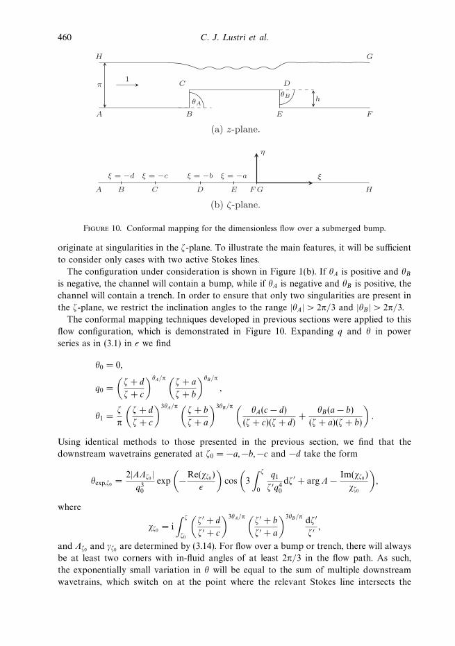
Figure 10. Conformal mapping for the dimensionless flow over a submerged bump.
originate at singularities in the &-plane. To illustrate the main features, it will be su"cient
to consider only cases with two active Stokes lines.
The configuration under consideration is shown in Figure 1(b). If "A is positive and "Bis negative, the channel will contain a bump, while if "A is negative and "B is positive, the
channel will contain a trench. In order to ensure that only two singularities are present in
the &-plane, we restrict the inclination angles to the range |"A| > 2!/3 and |"B | > 2!/3.
The conformal mapping techniques developed in previous sections were applied to this
flow configuration, which is demonstrated in Figure 10. Expanding q and " in power
series as in (3.1) in $ we find
"0 = 0,
q0 =
%& + d
& + c
&"A/! %& + a
& + b
&"B/!
,
"1 =&
!
%& + d
& + c
&3"A/! %& + b
& + a
&3"B/! %"A(c & d)
(& + c)(& + d)+
"B(a & b)
(& + a)(& + b)
&.
Using identical methods to those presented in the previous section, we find that the
downstream wavetrains generated at &0 = &a,&b,&c and &d take the form
"exp,&0 =2|A0&0 |
q30
exp
%&Re(/&0 )
$
&cos
%3
! &
0
q1
& *q40
d& * + arg0 & Im(/&0 )
/&0
&,
where
/&0 = i
! &
&0
%& * + d
& * + c
&3"A/! %& * + b
& * + a
&3"B/! d& *
& * ,
and 0&0 and .&0 are determined by (3.14). For flow over a bump or trench, there will always
be at least two corners with in-fluid angles of at least 2!/3 in the flow path. As such,
the exponentially small variation in " will be equal to the sum of multiple downstream
wavetrains, which switch on at the point where the relevant Stokes line intersects the
Free surface flow past topography 461
x!5 5 10!10 0
!0.1
y
(a) "A = "B = !2 (solid),
"A = "B = 3!8 (grey).
x
y
!5!15 5 10 15!10 0
0.1
(b) "A = "B = !!2 (solid),
"A = "B = ! 3!8 (grey).
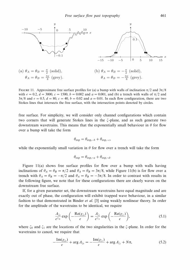
Figure 11. Approximate free surface profiles for (a) a bump with walls of inclination !/2 and 3!/8with $ = 0.2, d = 3000, c = 1500, b = 0.002 and a = 0.001, and (b) a trench with walls of !/2 and3!/8 and $ = 0.5, d = 80, c = 40, b = 0.02 and a = 0.01. In each flow configuration, there are twoStokes lines that intersects the free surface, with the intersection points denoted by circles.
free surface. For simplicity, we will consider only channel configurations which contain
two corners that will generate Stokes lines in the &-plane, and as such generate two
downstream wavetrains. This means that the exponentially small behaviour in " for flow
over a bump will take the form
"exp = "exp,&b + "exp,&c,
while the exponentially small variation in " for flow over a trench will take the form
"exp = "exp,&a + "exp,&d.
Figure 11(a) shows free surface profiles for flow over a bump with walls having
inclinations of "A = "B = !/2 and "A = "B = 3!/8, while Figure 11(b) is for flow over a
trench with "A = "B = &!/2 and "A = "B = &3!/8. In order to contrast with results in
the following figure, we note that for these configurations there are clearly waves on the
downstream free surface.
If, for a given parameter set, the downstream wavetrains have equal magnitude and are
exactly out of phase, the configuration will exhibit trapped wave behaviour, in a similar
fashion to that demonstrated in Binder et al. [3] using weakly nonlinear theory. In order
for the amplitude of the wavetrains to be identical, we require
0&0
$.&0exp
%&Re(/&0 )
$
&=
0&1
$.&1exp
%&Re(/&1 )
$
&, (5.1)
where &0 and &1 are the locations of the two singularities in the &-plane. In order for the
wavetrains to cancel, we require that
& Im(/&0 )
$+ arg0&0 = & Im(/&1 )
$+ arg0&1 + N!, (5.2)
462 C. J. Lustri et al.
x!5 5 10!10 0
!0.1
y
(a) "A = "B = !2 (solid),
"A = "B = 3!8 (grey).
.
x!5 5 10!10 0
!0.1
y
(b) "A = !2 , "B = 3!
8
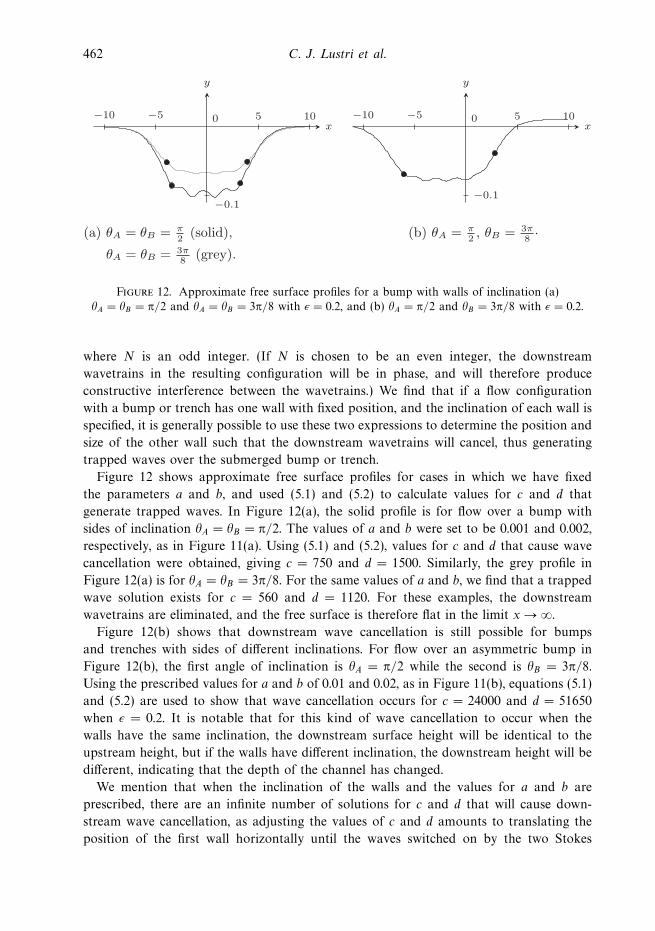
Figure 12. Approximate free surface profiles for a bump with walls of inclination (a)"A = "B = !/2 and "A = "B = 3!/8 with $ = 0.2, and (b) "A = !/2 and "B = 3!/8 with $ = 0.2.
where N is an odd integer. (If N is chosen to be an even integer, the downstream
wavetrains in the resulting configuration will be in phase, and will therefore produce
constructive interference between the wavetrains.) We find that if a flow configuration
with a bump or trench has one wall with fixed position, and the inclination of each wall is
specified, it is generally possible to use these two expressions to determine the position and
size of the other wall such that the downstream wavetrains will cancel, thus generating
trapped waves over the submerged bump or trench.
Figure 12 shows approximate free surface profiles for cases in which we have fixed
the parameters a and b, and used (5.1) and (5.2) to calculate values for c and d that
generate trapped waves. In Figure 12(a), the solid profile is for flow over a bump with
sides of inclination "A = "B = !/2. The values of a and b were set to be 0.001 and 0.002,
respectively, as in Figure 11(a). Using (5.1) and (5.2), values for c and d that cause wave
cancellation were obtained, giving c = 750 and d = 1500. Similarly, the grey profile in
Figure 12(a) is for "A = "B = 3!/8. For the same values of a and b, we find that a trapped
wave solution exists for c = 560 and d = 1120. For these examples, the downstream
wavetrains are eliminated, and the free surface is therefore flat in the limit x $ ).
Figure 12(b) shows that downstream wave cancellation is still possible for bumps
and trenches with sides of di!erent inclinations. For flow over an asymmetric bump in
Figure 12(b), the first angle of inclination is "A = !/2 while the second is "B = 3!/8.
Using the prescribed values for a and b of 0.01 and 0.02, as in Figure 11(b), equations (5.1)
and (5.2) are used to show that wave cancellation occurs for c = 24000 and d = 51650
when $ = 0.2. It is notable that for this kind of wave cancellation to occur when the
walls have the same inclination, the downstream surface height will be identical to the
upstream height, but if the walls have di!erent inclination, the downstream height will be
di!erent, indicating that the depth of the channel has changed.
We mention that when the inclination of the walls and the values for a and b are
prescribed, there are an infinite number of solutions for c and d that will cause down-
stream wave cancellation, as adjusting the values of c and d amounts to translating the
position of the first wall horizontally until the waves switched on by the two Stokes
Free surface flow past topography 463
x!5 5 10!10 0
!0.1
y
(a) "A = "B = !2 (solid),
"A = "B = 3!8 (grey).
x
y
!5!15 5 10 15!10 0
0.1
(b) "A = "B = !!2 (solid),
"A = "B = ! 3!8 (grey).
x!5 5 10!10 0
!0.1
y
(c) "A = "B = (solid),
"A = "B = (grey).
x!5 5 10!10 0
!0.1
y
(d) "A = , "B = .!23!8
!2
3!8
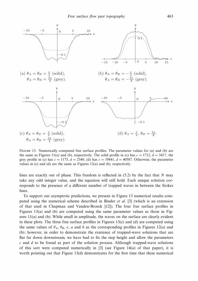
Figure 13. Numerically computed free surface profiles. The parameter values for (a) and (b) arethe same as Figures 11(a) and (b), respectively. The solid profile in (c) has c = 1712, d = 3417; thegrey profile in (c) has c = 1175, d = 2348; (d) has c = 19841, d = 40587. Otherwise, the parametervalues in (c) and (d) are the same as Figures 12(a) and (b), respectively.
lines are exactly out of phase. This freedom is reflected in (5.2) by the fact that N may
take any odd integer value, and the equation will still hold. Each unique solution cor-
responds to the presence of a di!erent number of trapped waves in between the Stokes
lines.
To support our asymptotic predictions, we present in Figure 13 numerical results com-
puted using the numerical scheme described in Binder et al. [3] (which is an extension
of that used in Chapman and Vanden-Broeck [12]). The four free surface profiles in
Figures 13(a) and (b) are computed using the same parameter values as those in Fig-
ures 11(a) and (b). While small in amplitude, the waves on the surface are clearly evident
in these plots. The three free surface profiles in Figures 13(c) and (d) are computed using
the same values of "A, "B , $, a and b as the corresponding profiles in Figures 12(a) and
(b); however, in order to demonstrate the existence of trapped-wave solutions that are
flat far down downstream, we have had to fix the step height and allow the parameters
c and d to be found as part of the solution process. Although trapped-wave solutions
of this sort were computed numerically in [3] (see Figure 14(a) of that paper), it is
worth pointing out that Figure 13(d) demonstrates for the first time that these numerical
464 C. J. Lustri et al.
solutions exist for flows past a bump with di!erent angles of inclination. We see that
numerically computed free surface profiles in Figure 13 compare very well with the asymp-
totic approximations in Figures 11 and 12. Our main emphasis, however, is to use the
numerical results to support our argument that the asymptotic results valid in the limit
$ $ 0 can be used to predict and explain qualitative behaviour of free surface flows more
generally.
The examples presented above in Figures 11 and 12 should be enough to illustrate the
power of using this analysis to describe the variety of flow regimes. By extending these
ideas, it is easy to see that for configurations that have three or four corners with an
in-fluid angle greater than 2!/3, it is possible that some of the downstream wavetrains
could cancel, while others remain. If the two dominant downstream wavetrains cancel,
then the resultant flow could only have a single downstream wavetrain, exponentially
small compared to the trapped waves. Additionally, if there are four corners with an
in-fluid angle greater than 2!/3, it is possible that a, b, c and d may be chosen so that the
two dominant wavetrains and the two subdominant wavetrains are of equal amplitude
and opposite phase. This leads to both the dominant and subdominant waves being
trapped, and therefore the free surface is flat far downstream.
6 Discussion
In this study, we have applied the beyond-all-orders framework developed in [12] to
two specific examples of steady two-dimensional free surface flow: flow over an inclined
step (Figure 1(a)) and flow over a bump/trench with inclined sides (Figure 1(b)). These
examples are characterised by having a di!erent number of Stokes lines, depending
on the angles of inclination of the bottom obstruction. We have illustrated a variety
of possibilities, including those that exhibit intermediate wavetrains and trapped-wave
solutions. Numerical solutions have also been presented to support these scenarios. Note
we have not treated the limits that the Froude number F $ 0 with small obstacle height
! = h/H % F2 nor the distinguished limit F $ 0 with ! = O(F2), as done in [12] for the
step-up problem with "I = !/2. We expect, however, that the details will follow from [12]
closely. Further, we have not given much consideration to the limit "I $ ±!/3, for which
there appears to be interesting behaviour not previously encountered.
It is worth contrasting the results in this study to the analogous problem of surface-
tension driven flows past a bottom obstruction (ignoring the e!ects of gravity) in the limit
of small surface tension [11]. First, for that problem Stokes lines are generated by all
corners of the bottom obstruction, regardless of the in-fluid angle. Thus for the geometry
sketched in Figure 1(a), the authors in [11] state there will be exponentially small capillary
waves switched on at two points on the free surface for all step angles "I (see Figure 9
in [11]). Further, unlike in the present problem, while the phase of the capillary waves
will depend on the location of the corners, the amplitude of each wavetrain will be the
same. As a consequence, for flow over a step with angle "I , it is possible to have the two
wave forms cancelling each other in the capillary wave case, but not the gravity-driven
wave case.
We close by mentioning some open problems and extensions in this area. First, it
should not be di"cult to generalise the results in [12] and this paper to hold for
Free surface flow past topography 465
multiple obstructions on the channel bottom, such as those treated numerically in Binder
et al. [4] (see Figures 8 and 9 of that paper). Presumably it would be possible to describe the
switching across Stokes lines for each relevant singularity and thus construct trapped-wave
solutions as we have done here.
Second, we note that each example treated in [12] and this paper has had sharp corners,
with well-defined singularities in the &-plane. While the important point is that these are
singularities of the complexified free surface, it happens that they are also singularities on
the boundary of the physical flow field. For flows past curved bottom obstructions, such
as flow past a semi-circle [18], there are no in-fluid angles greater than 2!/3, but we would
still expect there to be exponentially small waves in the limit that the Froude number
F $ 0, suggesting there are Stokes lines that intersect the free surface. For these flows the
relevant singularities of the complexified free surface may be o! the real '-axis, although
for some geometries it may not be obvious where they are located, or whether they are of
the form treated in [12]. There are a plethora of configurations that could be addressed,
but once theory for curved solid boundaries is developed, one could solve problems such
as flow past a submerged ellipse [16], for example, with a view to explaining trapped
waves in the limit F $ 0.
Third, it would be interesting to compute accurate numerical solutions that demonstrate
the existence of intermediate waves (illustrated schematically in Figure 8) for Froude
numbers that are not small. Success in this regard would further support the argument
here and in [12] that qualitative features determined asymptotically in the limit $ $ 0
hold more generally.
Finally, it remains a significant challenge to address time-dependent free surface flows
using a beyond all orders approach, especially since the conformal mapping approaches
used here for steady flows can no longer be applied. It is worth noting, however, that for
the (nonlinear) crystal growth model proposed in [6] and studied using beyond all orders
techniques by [9,24] for example, linear time-dependent generalisations have been treated
successfully by [5, 10, 21]. The extent to which all these techniques can be applied to fully
nonlinear time-dependent free surface flows is as yet untested.
Acknowledgement
CJL thanks Professor Jonathan Chapman for his guidance and for many fruitful discus-
sions on exponential asymptotics.
References
[1] Berry, M. V. (1991) Asymptotics, superasymptotics, hyperasymptotics. In: H. Segur, S. Tanveer& H. Levine (editors), Asymptotics Beyond All Orders, Plenum, Amsterdam, pp. 1–14.
[2] Binder, B. J. (2010) Steady free-surface flow at the stern of a ship. Phys. Fluids, 22,012104.
[3] Binder, B. J., Dias, F. & Vanden-Broeck, J.-M. (2007) Influence of rapid changes in a channelbottom on free-surface flows. IMA J. Appl. Math. 73, 1–20.
[4] Binder, B. J., Vanden-Broeck, J.-M. & Dias, F. (2005) Forced solitary waves and fronts pastsubmerged obstacles. Chaos 15, 037106.
[5] Body, G. L., King, J. R. & Tew, R. H. (2005) Exponential asymptotics of a fifth-orderdi!erential equation. Euro. J. Appl. Math. 16, 647–681.
466 C. J. Lustri et al.
[6] Brower, R. C., Kessler, D. A., Koplik, J. & Levine, H. (1983) Geometrical approach tomoving-interface dynamics. Phys. Rev. Lett. 51, 1111–1114.
[7] Chapman, S. J. (1999) On the role of Stokes lines in the selection of Sa!man-Taylor fingerswith small surface tension. Euro. J. Appl. Math. 10, 513–534.
[8] Chapman, S. J. & King, J. R. (2003) The selection of Sa!man-Taylor fingers by kineticundercooling. J. Eng. Math. 46, 1–32.
[9] Chapman, S. J., King, J. R. & Adams, K. L. (1998) Exponential asymptotics and Stokeslines in nonlinear ordinary di!erential equations. Proc. Roy. Soc. Lond. A 454, 2733–2755.
[10] Chapman, S. J. & Mortimer, D. B. (2005) Exponential asymptotics and Stokes lines in apartial di!erential equation. Proc. Roy. Soc. Lond. A 461, 2385–2421.
[11] Chapman, S. J. & Vanden-Broeck, J.-M. (2002) Exponential asymptotics and capillary waves.SIAM J. Appl. Math. 62, 1872–1898.
[12] Chapman, S. J. & Vanden-Broeck, J.-M. (2006) Exponential asymptotics and gravity waves.J. Fluid Mech. 567, 299–326.
[13] Dagan, G. (1975) Waves and wave resistance of thin bodies moving at low speed: Thefree-surface nonlinear e!ect. J. Fluid Mech. 69, 405–416.
[14] Dingle, R. B. (1973) Asymptotic Expansions: Their Derivation and Interpretation, AcademicPress, New York.
[15] Doctors, L. J. & Dagan, G. (1980) Comparison of nonlinear wave-resistance theories for atwo-dimensional pressure distribution. J. Fluid Mech. 98, 647–672.
[16] Forbes, L. K. (1982) Non-linear, drag-free flow over a submerged semi-elliptical body. J. Eng.Math. 16, 171–180.
[17] Forbes, L. K. (1988) Critical free-surface flow over a semi-circular obstruction. J. Eng. Math.22, 3–13.
[18] Forbes, L. K. & Schwartz, L. W. (1982) Free-surface flow over a semicircular obstruction.J. Fluid Mech. 114, 299–314.
[19] Gazdar, A. S. (1973) Generation of waves of small amplitude by an obstacle placed on thebottom of a running stream. J. Phys. Soc. Japan 34, 530.
[20] Hocking, G. C. & Forbes, L. K. (1992) Subcritical free-surface flow caused by a line sourcein a fluid of finite depth. J. Eng. Math. 26, 455–466.
[21] Howls, C. J., Langman, P. J. & Olde Daalhuis, A. B. (2004) On the higher-order Stokesphenomenon. Proc. Roy. Soc. Lond. A 460, 2285–2303.
[22] King, A. C. & Bloor, M. I. G. (1987) Free-surface flow over a step. J. Fluid Mech. 182,193–208.
[23] King, A. C. & Bloor, M. I. G. (1990) Free-surface flow of a stream obstructed by an arbitrarybed topography. Q. J. Mech. Appl. Math. 43, 87–106.
[24] Kruskal, M. D. & Segur, H. (1991) Asymptotics beyond all orders in a model of crystalgrowth. Stud. Appl. Math. 36, 129–181.
[25] Lamb, H. (1932) Hydrodynamics. Cambridge University Press.[26] Maleewong, M. & Grimshaw, R. H. J. (2008) Nonlinear free surface flows past a semi-infinite
flat plate in water of finite depth. Phys. Fluids 20, 062102.[27] McCue, S. W. & Forbes, L. K. (1999) Bow and stern flows with constant vorticity. J. Fluid
Mech. 399, 277–300.[28] McCue, S. W. & Forbes, L. K. (2002) Free-surface flows emerging from beneath a semi-infinite
plate with constant vorticity. J. Fluid Mech. 461, 387–407.[29] McCue, S. W. & Stump, D. M. (2000) Linear stern waves in finite depth channels. Q. J. Mech.
Appl. Math. 53, 629–643.[30] Mekias, H. & Vanden-Broeck, J.-M. (1991) Subcritical flow with a stagnation point due to a
source beneath a free surface. Phys. Fluids A 3, 2652–2658.[31] Ogilat, O., McCue, S. W., Turner, I. W., Belward, J. A. & Binder, B. J. (2011) Minimising
wave drag for free surface flow past a two-dimensional stern. Phys. Fluids 23, 072101.
Free surface flow past topography 467
[32] Ogilvie, T. F. (1968) Wave Resistance. The Low Speed Limit. Technical Report, MichiganUniversity, Ann Arbor, MI.
[33] Olde Daalhuis, A. B., Chapman, S. J., King, J. R., Ockendon, J. R. & Tew, R. H. (1995)Stokes phenomenon and matched asymptotic expansions. SIAM J. Appl. Math. 55, 1469–1483.
[34] Scullen, D. & Tuck, E. O. (1995) Nonlinear free-surface flow computations for submergedcylinders. J. Ship Res. 39, 185–193.
[35] Trinh, P. H., Chapman, S. J., & Vanden-Broeck, J.-M. (2011) Do waveless ships exist? Resultsfor single-cornered hulls. J. Fluid Mech. 685, 413–439.
[36] Tuck, E. O. & Scullen, D. C. (1998) Tandem submerged cylinders each subject to zero drag.J. Fluid Mech. 364, 211–220.
[37] Vanden-Broeck, J.-M. (1980) Nonlinear stern waves. J. Fluid Mech. 96, 603–611.[38] Vanden-Broeck, J.-M., Schwartz, L. W. & Tuck, E. O. (1978) Divergent low-Froude-number
series expansion of nonlinear free-surface flow problems. Proc. R. Soc. Lond. A 361, 207–224.[39] Vanden-Broeck, J.-M. & Tuck, E. O. (1977) Computation of near-bow or stern flows using
series expansion in the Froude number. In: 2nd International Conference on Numerical ShipHydrodynamics, University of California, Berkeley, CA.
[40] Vanden-Broeck, J.-M. & Tuck, E. O. (1985) Waveless free-surface pressure distributions. J.Ship Res. 29, 151–158.
[41] Wehausen, J. V. & Laitone, E. V. (1960) Surface waves. In: Handbuch der Physik, Springer,pp. 446–778.
[42] Zhang, Y. & Zhu, S. (1996) A comparison of nonlinear waves generated behind a semicirculartrench. Proc. Roy. Soc. Lond. A 452, 1563–1584.
[43] Zhang, Y. & Zhu, S. (1996) Open channel flow past a bottom obstruction. J. Eng. Math. 30,487–499.


![Adaptivefinitevolumemethodswithwell-balanced Riemann ...The Riemann solver described in [18] was developed for general flow over topography, and was developed with the goal of accurately](https://img.pdfslide.net/doc/110x75/61234e3b7a3dd6524f41cc76/adaptiveinitevolumemethodswithwell-balanced-riemann-the-riemann-solver-described.jpg)