Embed Size (px)
Citation preview

Cutler-Hammer I.B. 8926-1AModel A
Effective 3/01
Freedom 2100 Motor Control CenterInstallation and Maintenance Manual
TABLE OF CONTENTS
PART DESCRIPTION PAGE
1 General Information 2
2 Receiving, Handling, & Storage 4
3 Installing Control Center Sections 5
4 Installing Conduit & Wiring 10
5 Incoming Line Connections 12
6 Overcurrent Protection Devices 14
7 Overload Relay Heater Selection 16
8 Inspection Prior to Energizing 19
9 Unit Installation & Adjustment 20
10 Maintenance 23
11 Plan Views 31
12 Related Instruction Leaflets 33
This electrical control equipment is designed to beinstalled, operated, and maintained by adequatelytrained workmen. These instructions do not cover alldetails, variations, or combinations of the equipment, itsstorage, delivery, installation, check-out, safe operation,or maintenance. Care must be exercised to comply withlocal, state, and national regulations, as well as safetypractices, for this class of equipment. The maximumshort circuit capability of the equipment should not beexceeded by connection to a source with highercapacity.
If maintenance or troubleshooting assistance is required,contact your nearest Cutler-Hammer Sales Office.

2 I.B. 8926-1A
Part 1GENERAL INFORMATION
THE MOTOR CONTROL CENTER
The Cutler-Hammer Freedom 2100 Motor ControlCenter may be joined to existing Five Star, Series2100, and Advantage installations using the splicebar kits common to both. Units designed for theFreedom 2100 can be mounted in Five Star Seriesand Series 2100 sections, but the opposite is notrecommended, because Five Star and Series 2100units may lack terminal blocks and sufficientinterrupting capacity. The Freedom 2100 MCCmay be joined to existing Cutler-Hammer FreedomUnitrol and F10 Unitrol MCC’s with a special splicebar kit, but units are not interchangable.
CONTROL CENTER NOMENCLATURE
The numbers shown in parentheses in thefollowing text refer to the balloon legends in Figure2.The Cutler-Hammer Freedom 2100 Motor ControlCenter consists of one or more totally enclosed,dead front, free standing structural assemblies (17)90 inches high which are compartmentalized tohouse individual control units. (2) With control unitsmounted in the front side only, the structure maybe 16 or 21 inches deep. For mounting units back-to-back, the structure is 21 inches deep. Steelcovers (7) enclose the structure at the top, sidesand at the rear of front-mounted-only structures.
A vertical bus system (13) installed in each verticalsection is connected to the horizontal bus to feedthe individual control units. (14) The vertical bus isisolated by a full height barrier. (6) An optionallabyrinth barrier provides both isolation andinsulation. An automatic shutter is included with thelabyrinth barrier system to cover the stab openingsfor each control unit.
At the top of each section, a door provides readyaccess to the top horizontal wireway (11) andground bus (8). The horizontal wireway is isolatedfrom the bus systems by steel barriers (10) whichcan be removed for installation and maintenanceoperations. Adequate space is provided for controlwiring and top cable entry.
At the bottom of each section, a door (18) providesready access to the bottom horizontal wireway,(19) and neutral bus (if provided). The bottom ofeach section is completely open to provide
unrestricted bottom entry of cable and conduit.Channel sills may be installed across the bottom ofthe control center if specified, and an optionalbottom plate may also be specified.
A vertical wireway 8 inches deep, (16) extendingthe full 90 inch height of the control center islocated to the right of each unit compartment. Thiswireway is covered by two hinged doors (15) andcontains cable supports to secure wire bundlesand cables. The vertical wireway joins thehorizontal wireway at the top and bottom to provideunobstructed space for interwiring.
Each vertical section provides space to mount upto six controller units (2) with a minimum height of12 inches, in increments of six inches, for a total of72 inches of usable space. Controllers throughNEMA Size 5 are drawout type (except reduced-voltage starters). These drawout unit assembliesare a completely self-contained package consistingof a steel enclosure, operating handle andelectrical components. The drawout assemblyslides into this compartment on guide rails (11) toprovide easy withdrawal and reinsertion and toensure precise alignment of the unit stabs with thevertical bus. Each drawout unit is held in place by asingle quarter-turn latch (4) which can only beengaged when the unit stabs are fully mated withthe vertical bus. Each unit has a separate door, (1)held closed by a minimum of two quarter-turnfasteners.
The operating handle on the controller unit (3)moves vertically. In the ON or TIPPED positions,the handle interlocks with the unit door to preventits opening. In this position, authorized personnelcan open the door by turning the defeatermechanism screw. (21) With the unit door open
Fig. 1 Nameplate

3 I.B. 8926-1A
Fig. 2 Motor Control Center Nomenclature
and the operating handle in the ON position,another interlock to the divider pan preventsremoval of the unit. This same interlock preventsinsertion of the unit unless the handle mechanismis in the OFF position. To ensure that units are notenergized accidentally or by unauthorized
personnel, the handle mechanism can bepadlocked in the OFF.position. Space for aminimum of three padlocks is provided on eachhandle.The device panel (5) is mounted on thedrawout unit. It will accommodate up to six pilotdevices. The overload reset button (20) is mountedon the unit door.
(1)Unit Door
(2)DrawoutUnit
(4)¼ Turn Latch
(3)OperatingHandle
(5)Device Paneland Devices
(7)Top & SideCovers
(6)Vertical Bus Barrier– Labyrinth(Optional)
(8) Ground Bus (9) Top HorizontalWireway
(10) Horizontal BusBarriers
(12)Horizontal
Bus
(13)Vertical
Bus
(11)Divider Pan/Guide Rails
(14)Vertical Bus
Barrier -Standard
(15)Vertical
WirewayDoor
(16)Vertical
Wireway
(17)StructuralMembers(18)
BottomHorizontalWireway Door
(19)BottomHorizontalWireway
(20)OverloadReset Button
(21)DefeaterMechanism Screw

4 I.B. 8926-1A
RATINGS
Each Freedom 2100 Motor Control Center has arating nameplate attached to the door of the tophorizontal wireway of the primary section. SeeFigures 1 and 2. This nameplate shows the generalorder number under which the motor control centerwas built and its continuous electrical ratings, interms of incoming line voltage, phases, andfrequency, and ampere ratings of the horizontal busand the vertical bus for each section. In addition, thisnameplate shows the passive short-circuit(withstand) rating of the horizontal and vertical bussystem.
The active short-circuit (interrupting) ratings of themain and unit short-circuit protective devices areshown on labels attached to the inside of each unit.Before installing a motor control center, calculateand record the fault current available at the incomingline terminals. Verify that the short-circuit withstandand short-circuit interrupting ratings of the units in
the motor control center are appropriate for the faultcurrent available.
QUALIFIED PERSONNEL
Individuals who install, operate or maintain motorcontrol centers must be trained and authorized tooperate the equipment associated with theinstallation and maintenance of a motor controlcenter, as well as the operation of the equipmentthat receives its power from controller units in themotor control center.
Such individuals must be trained in the properprocedures with respect to disconnecting andlocking OFF power to the motor control center,wearing protective clothing and equipment, andfollowing established safety procedures as outlinedin the National Electrical Safety Code(ANSI C2)and Electrical Equipment Maintenance(NFPA70B).
Part 2RECEIVING, HANDLING, AND STORAGE
RECEIVING
Before and after unloading the motor control center,inspect each section and unit exterior for evidence ofdamage that may have been incurred duringshipment. If there is any indication that the controlcenter has been mishandled or shipped on its backor side, remove the drawout units and make acomplete inspection of the internal structure, busbars, insulators and unit components for possiblehidden damage. Report any damage found to thecarrier at once.
HANDLING
The following guidelines are provided to help avoidpersonal injury and equipment damage duringhandling, and to facilitate moving the motor controlcenter at the job site.
GENERAL HINTS
1. Handle the motor control center with care, toavoid damage to components and to theenclosure or its paint finish.
2. Keep the motor control center in an uprightposition.
3. Insure that the moving means has the capacityto handle the weight of the motor control center.
4. The control center should remain secured to theshipping skid until the motor control center is inits final location.
5. Exercise care during any movement andplacement operations to prevent falling orunintentional rolling or tipping.
6. Lifting angles for handling by overhead craneare bolted to the top of each shipping section.Handling by overhead crane is preferable butwhen crane facilities are not available, the motorcontrol center can be positioned with a fork-lifttruck or by using rollers under the shipping skid.
OVERHEAD CRANE
1. See Figure 3 for recommended liftingconfiguration.
2. Select or adjust the rigging lengths tocompensate for any unequal weight distribution,and to maintain the motor control center in anupright position.
3. To reduce tension on the rigging and thecompressive load on the lifting angles, do notallow the angle between the lifting cables andvertical to exceed 45 degrees.
4. Use slings with safety hooks or shackles. Donot pass ropes or cables through liftingangle holes.

5 I.B. 8926-1A
Figure 3 Correct Use Of Lifting Angle
5. After removing the lifting angles, replace themounting hardware to prevent the entrance of dirt,etc.
FORK-LIFT TRUCK
Motor control centers are normally top and frontheavy. Balance the load carefully and steady, asnecessary, while moving. Always use a safetystrap when handling with a fork-lift.
ROLLERS
Rod or pipe rollers, with the aid of pinch bars,provide a simple method of moving the motor controlcenter on one floor level, if there is no significantincline. Roll the motor control center slowly, andsteady the load to prevent tipping.
STORAGE
When a motor control center cannot be installed andplaced into operation immediately upon receipt, takesteps to prevent damage by condensation or harshenvironmental conditions. If the motor control centercannot be installed in its final location, store it in aclean, dry, ventilated building, heated to preventcondensation, and protected from dirt, dust, water,and mechanical damage. When storage conditionsare less than ideal, install temporary electricalheating, typically in the form of light bulbs, totaling150 watts per section, hung in the vertical wireway,or by applying power to self-contained spaceheaters that the motor control center may beequipped with. Remove all loose packing andflammable materials before energizing any of theheating elements.
Part 3INSTALLING CONTROL CENTER SECTIONS
GENERAL
Freedom Series 2100 Motor Control Centers(MCC’s) are designed for installation in accordancewith both the National Electrical code (NEC), NFPA70, and the National Electrical Safety Code (NESC),ANSI C2.
Caution – If work is involved in connecting thecontrol center with existing equipment, ensurethat incoming power is disconnected beforework is begun. Disconnecting means should belocked out and/or tagged out of service. Where itis not feasible to de-energize the system, thefollowing precautions should be taken:
A) Persons working near exposed parts that are ormay be energized should be instructed and shoulduse practices (including appropriate apparel,equipment, and tools) in accordance with the NESC.
B) Persons working on exposed parts that are ormay be energized should, in addition, be qualifiedpersons who have been trained to work onenergized circuits.
INSTALLATION
1. Before any installation work is begun, consult alldrawings furnished by Cutler-Hammer as well asall applicable contract drawings for theinstallation. Give particular attention to thephysical location of units in the control centerand their relation to existing or planned conduit,busways, etc. Provide for future conduitentrance prior to control center installation.
2. Locate the control center in the area shown onthe building floor plans. If in a wet location oroutside of the building, protect the control centerfrom water entering or accumulation within theenclosure. Recommended clearances orworking spaces are as follows:a) Clearance from walls (where not rear
accessible) – a minimum of ½ inch forindoor and 6 inches for outdoor or wetlocations.
b) Clearance from front of MCC (workingspace) – minimum of 3 feet for controlcenters without exposed live parts. See NEC110-16d. NOTE: This working space should
6 I.B. 8926-1A
not be used for storage and should haveadequate lighting.
3. Since control centers are assembled at thefactory on smooth and level surfaces to assurecorrect alignment of all parts, control centersshould be securely mounted on a level surface.The foundation furnished by the purchaser mustbe true and level, or the bottom frames must beshimmed to support the entire base in a trueplane. It is recommended that leveled channelsills under both the front and rear of the controlcenter be used to provide this level base. Drill antap the channel sills for mounting bolts inaccordance with the applicable floor plandrawing and then either install the MCC levelwith, or on top of, the finished floor. If sills aregrouted in concrete, the mounting bolts shouldbe screwed in place and remain until theconcrete has hardened.
4. For bottom entry, position the motor controlcenter so that the conduit stubs or flooropenings are located in the shaded areas shownon the MCC floor plan drawings (refer to pages31 to 32 for floor plan dimensions). The shadedareas represent the open space available forconduit entry through the bottom of eachsection. A shaded area may be restricted if largecontrollers or autotransformers are mounted inthe bottom of the sections. If optional bottomplates are supplied, the plates may be removedand drilled for conduit entry.
5. Install the MCC in its final position, progressivelyleveling each section and bolting the framestogether if they are separated. If necessary,secure the MCC to walls or other supportingsurfaces. Do not depend on wooden plugsdriven into holes in masonry, concrete, plaster,or similar materials. See NEC 110-13.
6. If two or more shipping sections are to be joinedinto an integral assembly or a shipping section isto be joined to an existing section, refer toparagraphs below before proceeding with theinstallation.
7. Ground and bond the motor control center asfollows:a) Motor control centers used as service
equipment for a grounded system or as anincoming line section for a separately-derived previously grounded system:i) Run a grounding electrode conductor
(ground wire) having a size inaccordance with NEC 250-94 from thegrounding electrode to the MCC groundbus or ground terminal provided. Seealso NEC 250-91(a) and 92(b).
ii) If the system is grounded at any pointahead of the MCC, the grounded
conductor must be run to the MCC inaccordance with NEC 250-23(b), andconnected to the ground bus terminal.
iii) Do not make any connections to groundon the load side of any neutraldisconnecting line or any sensor used forground-fault protection. Do not connectoutgoing grounding conductors to theneutral.
b) Motor control centers used as serviceequipment for an ungrounded system or asan incoming line section for a separately-derived previously ungrounded system:i) Run a grounding electrode conductor
(ground wire) having a size inaccordance with NEC 250-94 from thegrounding electrode to the MCC groundbus terminal. See NEC 250-91(a) and92(b).
c) Motor control centers not used as serviceequipment nor as an incoming line sectionfor a separately-derived system, and usedon either a grounded or ungrounded system:i) Ground the MCC ground bus by means
of equipment grounding conductorshaving a size in accordance with NEC250-95 or by bonding to the racewayenclosing the main supply conductors inaccordance with NEC 250-91(b).
8. When all wiring and adjustments are complete,close all unit and wireway doors.
9. In damp indoor locations, shield the MCC toprevent moisture and water from entering andaccumulating.
10. Unless the motor control center has beendesigned for unusual service conditions, itshould not be located where it will be exposed toambient temperatures above 40°C (104°F),corrosive or explosive fumes, dust, vapors,dripping or standing water, abnormal vibration,shock or tilting.
JOINING COMPATIBLE SECTIONS
If two more shipping blocks are to be joined into anintegral assembly, or a section added to an existinginstallation, splicing or horizontal bus, ground bus,neutral bus and joining of the adjacent verticalsections must be planned with the installation.1. Remove the side sheets from adjacent vertical
sections to be joined. (These sheets will havebeen removed from factory-assembledsections.)
2. The horizontal bus splice plates and connectionhardware will be shipped with the MCC attachedto one end of shipping section. Refer to Figure4. This method provides the most convenient

7 I.B. 8926-1A
access to the bolts, and eliminates the need toremove the horizontal bus barriers in thatstructure. Should the existing bus be oxidized,sand lightly with a fine aluminum oxide paper.CAUTION – Do not use emery cloth or anyabrasive containing metal.
3. Remove the upper horizontal wireway door fromthe structure on the right side of the left-hand(LH) section and remove the two-piecewireway barrier to provide access to the ends ofthe bus in that section.
4. Move the section in place, aligning the uprightstructural channels and bottom channels.Alignment of the section with floor sills andfoundation provisions will be facilitated byremoving the bottom horizontal wireway doors.Using the “U” type frame clamps provided,clamp adjacent front upright channels togetherat the top, bottom and approximate center of thevertical structure. This operation will befacilitated by removing the vertical wirewaydoors from the left-hand structure and one ormore drawout units from the right-handstructure. See Part 9.
5. If rear access is available, “U” clamps shouldalso be used to clamp the rear upright channelstogether. In front-mounted-only structures thiswill require removal of the adjacent back sheets.In a back-to-back mounted structure, remove thevertical wireway doors and one or more drawoutunits as above.
6. Secure the sections to the floor sills or mountingbolts as provided for the installation.
7. Bolt the horizontal bus splice plates to the bus inthe left-hand structure, torquing all bus splicebolts to 360 pound-inches (30 pound-feet). SeeFigure 5.
8. Replace all unit, bus barriers, and doors.
JOINING INCOMPATABLE SECTIONS
Joining a Freedom 2100 Motor Control Center toother equipment such as Type W and 11-300Control Centers will usually involve a transitionsection, installed between the two varieties ofequipment. This transition section will be detailed ondrawings provided by Cutler-Hammer and theapplicable contact drawings. If provided separately,it should be installed first. Review the overallinstallation task to determine whether the transitionsection should be attached to the existing equipmentor to the Freedom 2100 section, before it is movedinto place, and select the sequence which willprovide best access to bus splicing and joining of thestructures.
Figure 4 Splice Plates Attached to RH Section
Figure 6 Single Bar Splice Kit

8 I.B. 8926-1A
SPLICE PLATES
Each splice plate kit consists of short pieces of busbar the same width as the main horizontal bus of theMCC the kit is shipped with, four bolts per phase,and appropriate quantities of related hardware. For asingle bus bar per phase the hardware is used asshown in Figure 6 for either 16” or 20” deepenclosures. Each splice plate is punched withrectangular holes to accept a square shank carriagebolt that will not rotate as the nut is tightened.
Where the MCC is built with two horizontal bus barsper phase, the splice plates are installed as shownin Figure 7. The top edge of Figures 7 through 10represents the backside of the MCC. The top portionof each of these figures applies to 20” deepenclosures and the lower portion to 16” deepenclosures. Note that for all but the single-bar perphase (Figure 6) installation, the16” deep enclosuresrequire the use of a nut plate that is mounted withthe same carriage bolt used to attach the horizontalbus bars to the channel-shaped insulators. Installthese nut plates before mounting the splice plates.Tighten the splice plate bolts with a driving torque of360 pound-inches (30 pound-feet).
Fig. 7 Double Bar Splice Kit
Fig. 8 Triple Bar Splice Kit
TYPE 3R ENCLOSURES
Where the MCC is supplied in a Type 3R enclosurefor an outdoor application, apply roof splice caps ateach shipping block junction to maintain theenclosure integrity.
Fig. 9 Quadruple Bar Splice Kits

9 I.B. 8926-1A
Fig. 10 Six and Eight Bar Splice Kits
JOINING FREEDOM 2100 TO FREEDOM UNITROL OR F10 UNITROL
Consult the assembly instruction supplied with every Freedom 2100 Motor Control Center set up for splice toFreedom Unitrol or F10 Unitrol.
Fig. 11 Splice Plates Attached to Freedom 2100Horizontal Bus and Ground Bus at Top.
Fig. 12 Horizontal Bus Splice Freedom Unitrol onLeft, Freedom 2100 on Right.
10 I.B. 8926-1A
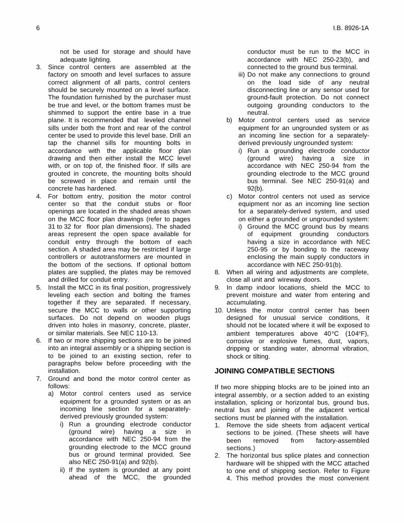
Fig. 13 Splice Plate Attached to Freedom 2100Ground Bus at Bottom.
Fig. 14 Splice Plate Attached to Freedom 2100Neutral Bus.
Part 4INSTALLING CONDUIT AND WIRING
CONDUIT
Install conduit in such a manner as to prevent waterfrom entering and accumulating in the conduit or theenclosure. Eliminate sags in conduit. Have theconduit enter the motor control center (MCC) in theareas designated for conduit entry on the planviews. See pages 31 and 32 of this booklet andoutline drawings shipped with the MCC. Keepingconduit within the shaded areas shown in the planviews will avoid cable interference with structuralmembers and live bus. See Part 12.
WIRING
Install the line and load conductors sized inaccordance with the NEC. Use copper wire onlyfor control terminations. Use copper wire onlyfor power terminations unless they are marked“CU/AL”. Use conductors with a temperature ratingof 75°C or higher, but regardless of the insulationtemperature rating select the wire size on the basisof 75°C wire ampacity. Using a higher temperaturewire ampacity table often results in a smaller cross-
section of copper available for carrying heat awayfrom terminals.
Install insulated wire and cable at a temperaturesufficiently warm to prevent the insulation fromcracking or splitting.
When more than one conduit is run from a commonsource or to a common load, be sure to have eachconduit carry conductors from each phase and thesame number of conductors per phase. If the phase
conductors are not distributed uniformly, eddycurrents will be generated in the steel between theconduits.
Locate conductors within the MCC to avoid physicaldamage and to avoid overheating. Secure incomingpower lines in a manner adequate to withstand theforces which will act to separate the conductorsunder short-circuit conditions. Use the cable tiesfurnished in both horizontal and vertical wireways tosupport the load and interconnection wire. Use ashielded communications cable inside of flexiblemetal conduit to protect very low voltage signalstransmitted to or from a computer or programmablecontroller.
Lugs furnished with the MCC and its componentsare for Class B and Class C stranding. Verify thecompatibility of wire size, type, and stranding withthe lugs furnished. Where they are not compatible,change the wire or lugs accordingly. If crimp lugs areused, crimp with the tools recommended by themanufacturer.
Use care in stripping insulation to avoid nicking orringing the metal.
All field wiring to control units should be made inaccordance with the wiring drawings that arefurnished with the control center. Load and controlwiring can be brought in through the upper and/orlower horizontal wireways. Determine the type ofwiring installed in the control center (NEMA Type Bor C) and proceed per the following appropriateparagraph.
The phase sequence of the power circuit loadterminals (left-to-right: T1, T2, T3) in units

11 I.B. 8926-1A
mounted on the rear side of the MCC is oppositeto that of the load terminals in units mounted onthe front side of a back-to-back MCC. To obtainthe same direction of rotation for a motorconnected to a rear-mounted unit as for oneconnected to a front-mounted unit re-label theterminals in the rear-mounted unit: T3, T2, T1,and wire accordingly. Refer to the warningsticker supplied with rear-side units.
When making connections to the load terminals,be sure to leave sufficient slack in the wires sothat the unit can be withdrawn to the detentposition for maintenance. See page 20.
NEMA TYPE B WIRING
Each control unit is factory assembled with devicesinter-wired within the unit. In addition, all controlwiring is carried to unit terminal blocks mounted onthe right-hand side of the unit. See Figure 15. Bringthe field wiring of control wires from a horizontalwireway into the vertical wireway on the right-handside of the applicable control unit and terminatethem at the unit terminal blocks. Bring load wiringfrom the vertical wireway, under the bottom right-hand side of the unit, to terminations within the unit.
ENGAGING PULL-APART TERMINALBLOCKS
The male portion of the pull-apart terminal block islocated in a plastic bag tied to the pivot rod insidethe unit. This terminal block can be wired outside ofthe vertical wireway. To engage the terminal block,align the fingers of the male connector with the slotat the back of the female portion of the terminalblock. Then rotate the male portion forward and tothe left into the female portion of the terminal block.
Each male portion of the pull-apart terminal blockhas two cavities adjacent to the center terminalscrew to accept the blade of an electrician’sscrewdriver used to cam the block into and out ofengagement. Each male portion also has a rear slotthat can engage the edge of the unit frame where itcan be mounted for ease in trouble-shooting.
NEMA TYPE C WIRING
Each control unit is factory assembled with devicesinter-wired within the unit. In addition, all controlwiring is carried to unit terminal blocks on the side ofthe unit and from these unit blocks, along with loadwiring through Size 3, to master terminal blockslocated at the top or bottom of the structure. SeeFigure 16. Master terminal blocks can be either fixedor drawout mounted. In the drawout design theterminal blocks are rack mounted to permitwithdrawal of the entire assembly for ease of wiringduring installation and maintenance. Bring fieldwiring from the horizontal wireway to the masterterminal blocks except for load wiring larger thanSize 3. These latter load wires should be carried intothe vertical wireway and under the bottom right-handside of the unit to terminations within the unit.
Fig. 16 Master Terminal Blocks
Fig. 15 Unit Terminal Blocks

12 I.B. 8926-1A
Part 5INCOMING LINE CONNECTIONS
OVERCURRENT PROTECTION
All ungrounded conductors in a motor control center(MCC) installation require some form of overcurrentprotection in order to comply with Section 240-20 ofthe NEC. Such overcurrent protection for theincoming lines to the MCC is in the form of fuses ora circuit breaker located at the transformersecondary that supplies the MCC. The conductorsfrom the transformer secondary constitute the feederto the MCC, and the “10-foot rule” and the “25-footrule” of NEC, 240-21 apply. These latter exceptionsto the general rule allow the disconnect means and
Fig 17 Main Disconnect with Stab LoadConnections
overcurrent protection to be located in the MCC,provided the feeder taps from the transformer aresufficiently short and other requirements are met.
MAIN DISCONNECTS
A circuit breaker or a circuit interrupter combinedwith fuses controlling the power to the entire MCCmay provide the over-current protection required asdescribed above or may be a supplementarydisconnect (isolation) means. See Figures 17, 18,and 19.
Fig. 18 Main Circuit Breaker with Reverse Feed
Fig. 19 Main Circuit Breaker
13 I.B. 8926-1A
When the MCC has a main disconnect, bring theincoming lines (the feeders) to the line terminals ofthe circuit breaker or circuit interrupter. The load sideof the circuit breaker or the load side of the fusesassociated with the circuit interrupter has alreadybeen connected to the MCC bus bar distributionsystem. In the case of main disconnects rated 400amperes or less, this load connection is made bystab connections to vertical bus bars which connectto the horizontal bus distribution system. See Figure17.
INCOMING LINE LUGS
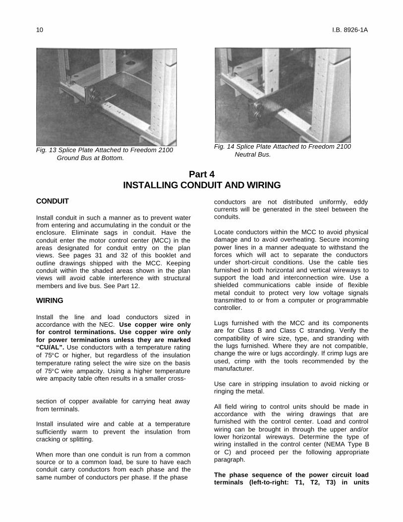
Where the overcurrent protection for the MCC is at aremote location, the MCC feeder lines areconnected to incoming line lugs attached to the busbar distribution system. See Figure 20. For high-ampere rated horizontal bus bar systems, theincoming line lugs are mounted on vertical risers,which connect to the horizontal bus bars. See Figure21.
SHORT-CIRCUIT BRACING
All incoming lines to either incoming line lugs or tomain disconnects must be braced to withstand themechanical forces created by a high fault current.With the remainder of a Freedom 2100 MCC braedfor not less than 65,000 amperes (rms symmetrical),the installing electrician needs to anchor the cablesat the incoming line connections sufficiently andtighten the lugs correctly. Each incoming linecompartment is equipped with a two-piece spreaderbar located about nine inches from the conduit entry.Use this spreader bar an appropriate lacing materialto tie cables together where they can be bundledand to hold them apart where they are separated. Inother words, position the incoming line cables andthen anchor them in place. See Figure 22 and theinstruction sheet inside of the MCC.
Fig.20 Incoming Line Lug Connections
Fig. 21 Incoming Line Compartment, 2000A
MAKING CONNECTION
CAUTION: All incoming line compartmentspresent an obvious hazard when the door isopened or covers are removed with power on.When working in this area, the incoming feedershould be de-energized.Before beginning work on incoming line connections,refer to all drawings furnished by Cutler Hammer aswell as all applicable contract drawings for theparticular installation.Depending on the location, size and type of theincoming arrangement, remove one or morehorizontal and vertical wireway doors, and selectedunits to provide complete access. See Part 9 for unitremoval instructions.
For top entry, the top cover plates are easilyremoved for drilling or punching operations.
Fig. 22 Spreader Bar For Top Entry
14 I.B. 8926-1A
Part 6OVERCURRENT PROTECTION DEVICES
DEVICE SELECTION
Articles 240 and 430 of the NEC contain the rules forselecting fuses, circuit breakers and overload relaysby type and by voltage and ampere rating. Followthese rules for feeder circuits, and the instructionsattached to the inside of the left-most verticalwireway door, for motor branch circuits. Select andinstall overload relay current elements (heaters)based on the motor service factor and full-loadcurrent. Ambient compensated overload relays areused in motor control centers (MCC’s) to offset thetemperature gradient which occurs from top tobottom in a loaded vertical section.
HEATERS MUST BE INSTALLED IN THESTARTER OVERLOAD RELAY ASSEMBLIESBEFORE THE STARTER IS ENERGIZED.
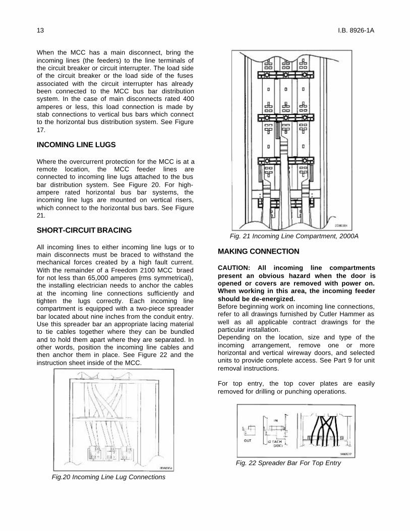
C306 THERMAL OVERLOAD RELAYS (FIG.24)
C306 Overload Relays are provided on FreedomStarters. Four sizes are available for overloadprotection up to 114 amperes. Features include:• Selectable Manual or Automatic Reset operation.• Interchangeable Heater Packs adjustable ±24%
to match motor FLA and calibrated for use with1.0 and 1.15 service factor motors.Heater packs for 32 ampere overload relay willmount in 75 ampere overload relay – useful in de-rating applications such as jogging.
• Class 10 or 20 heater packs. (Fig. 24) Use Class10 heaters with fusible or thermal magneticbreaker disconnects only.
• Bimetallic, ambient compensated operated. Tripfree mechanism.
• Electrically isolated NO – NC contacts (pullRESET button to test).
• Overload trip indication.• Single phase protection.• UL listed, CSA certified and NEMA compliance.
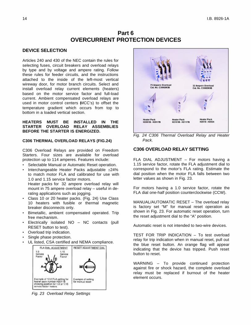
Fig. 23 Overload Relay Settings
Fig. 24 C306 Thermal Overload Relay and HeaterPack.
C306 OVERLOAD RELAY SETTING
FLA DIAL ADJUSTMENT – For motors having a1.15 service factor, rotate the FLA adjustment dial tocorrespond to the motor’s FLA rating. Estimate thedial position when the motor FLA falls between twoletter values as shown in Fig. 23.
For motors having a 1.0 service factor, rotate theFLA dial one-half position counterclockwise (CCW).
MANUAL/AUTOMATIC RESET – The overload relayis factory set “M” for manual reset operation asshown in Fig. 23. For automatic reset operation, turnthe reset adjustment dial to the “A” position.
Automatic reset is not intended to two-wire devices.
TEST FOR TRIP INDICATION – To test overloadrelay for trip indication when in manual reset, pull outthe blue reset button. An orange flag will appearindicating that the device has tripped. Push resetbutton to reset.
WARNING – To provide continued protectionagainst fire or shock hazard, the complete overloadrelay must be replaced if burnout of the heaterelement occurs.
15 I.B. 8926-1A
CURRENT TRANSFORMERS
When current transformers are used with overloadrelays, the current through the overload relay heateris related to the motor full-load by the inverse of thecurrent transformer ratio.
WARNING: Do not ever remove heaters from Size 5and larger starters to check unit operation. Thesestarters use current transformers to drop the currentto the range of the size 1 overload relay. Operationwith heaters removed will not interrupt voltage to themotor and will generate dangerous voltages in theopen secondary of the current transformer.
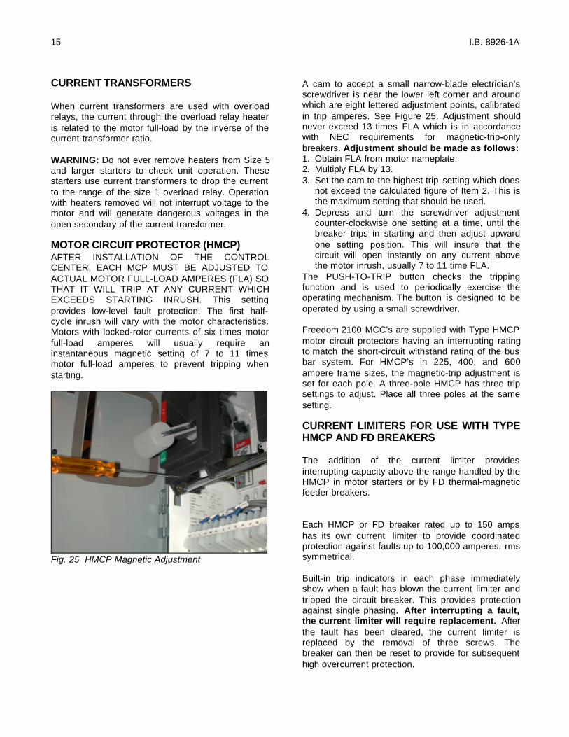
MOTOR CIRCUIT PROTECTOR (HMCP)AFTER INSTALLATION OF THE CONTROLCENTER, EACH MCP MUST BE ADJUSTED TOACTUAL MOTOR FULL-LOAD AMPERES (FLA) SOTHAT IT WILL TRIP AT ANY CURRENT WHICHEXCEEDS STARTING INRUSH. This settingprovides low-level fault protection. The first half-cycle inrush will vary with the motor characteristics.Motors with locked-rotor currents of six times motorfull-load amperes will usually require aninstantaneous magnetic setting of 7 to 11 timesmotor full-load amperes to prevent tripping whenstarting.
Fig. 25 HMCP Magnetic Adjustment
A cam to accept a small narrow-blade electrician’sscrewdriver is near the lower left corner and aroundwhich are eight lettered adjustment points, calibratedin trip amperes. See Figure 25. Adjustment shouldnever exceed 13 times FLA which is in accordancewith NEC requirements for magnetic-trip-onlybreakers. Adjustment should be made as follows:1. Obtain FLA from motor nameplate.2. Multiply FLA by 13.3. Set the cam to the highest trip setting which does
not exceed the calculated figure of Item 2. This isthe maximum setting that should be used.
4. Depress and turn the screwdriver adjustmentcounter-clockwise one setting at a time, until thebreaker trips in starting and then adjust upwardone setting position. This will insure that thecircuit will open instantly on any current abovethe motor inrush, usually 7 to 11 time FLA.
The PUSH-TO-TRIP button checks the trippingfunction and is used to periodically exercise theoperating mechanism. The button is designed to beoperated by using a small screwdriver.
Freedom 2100 MCC’s are supplied with Type HMCPmotor circuit protectors having an interrupting ratingto match the short-circuit withstand rating of the busbar system. For HMCP’s in 225, 400, and 600ampere frame sizes, the magnetic-trip adjustment isset for each pole. A three-pole HMCP has three tripsettings to adjust. Place all three poles at the samesetting.
CURRENT LIMITERS FOR USE WITH TYPEHMCP AND FD BREAKERS
The addition of the current limiter providesinterrupting capacity above the range handled by theHMCP in motor starters or by FD thermal-magneticfeeder breakers.
Each HMCP or FD breaker rated up to 150 ampshas its own current limiter to provide coordinatedprotection against faults up to 100,000 amperes, rmssymmetrical.
Built-in trip indicators in each phase immediatelyshow when a fault has blown the current limiter andtripped the circuit breaker. This provides protectionagainst single phasing. After interrupting a fault,the current limiter will require replacement. Afterthe fault has been cleared, the current limiter isreplaced by the removal of three screws. Thebreaker can then be reset to provide for subsequenthigh overcurrent protection.

16 I.B. 8926-1A
TYPE HMCP AND FD CIRCUIT BREAKERSWITH TERMINAL END COVERSCircuit breakers installed in units connected to 600volt distribution systems require a terminal end cap
to be installed on the line side. Replace the terminalend cap when replacing circuit breakers in suchunits.
Part 7OVERLOAD RELAY HEATER SELECTION
HEATER SELECTION AND INSTALLATION
Heaters should be selected on the basis of theactual full load current and service factor as shownon the motor nameplate or in the motormanufacturer’s published literature.
When motor and overload relay are in the sameambient and the service factor of the motor is 1.15 to1.25, select heaters and set FLA adjustment dialfrom the heater application table. If the servicefactor of the motor is 1.0, or there is no servicefactor shown, rotate the FLA adjustment dialcounter-clockwise one half (1/2) position.
The conductors attached to the terminals of anoverload relay act as a heat sink and are aconsideration in establishing the current rating ofeach heater element. To prevent nuisance tripping,which will occur if undersized conductors are used,select the wire size as if the conductors had aninsulation temperature rating of 75°C, even if theconductors actually used have a temperature ratinghigher than 75°C.
Protect heater and starter against short circuits byproviding branch circuit protection in accordancewith the National Electric Code.
Note: Before installing heater packs, refer to themotor nameplate for FLA (full load amps) andservice factor (1.5 or 1.0). Select the heater packfrom the proper table on this page.
To install:
A. Insert three (3) identically numbered heater packsinto the overload relay with an FLA rating thatincludes the motor nameplate FLA (full loadamps).
B. Tighten the heater pack mounting screwssecurely per recommended torque values listedbelow.
Heater Pack Numbers Recommended Torque
H2001B thru H2017BH2018 thru H2024
9 lb-in [1 N • m]24-30 lb-in [2.7-3.4 N • m]
C. Adjust the FLA adjustment dial tothe motor nameplate FLA (fullload amps).
THE OVERLOAD IS NOW SET FOR1.15 SERVICE FACTOR.
D. If the motor nameplate is 1.0service factor, rotate the FLAAdjustment dial counter-clockwiseon half (1/2) position.
E. The overload is factory set for M(MANUAL) reset operation. Ifautomatic reset is required, turnthe reset adjustment dial to A(AUTO). Automatic reset is notintended for two-wire controldevices.
Heater PackMounting Screw

17 I.B. 8926-1A
TO REMOVE HEATER PACKS
Loosen two (2) heater packs mounting screws andremove heater pack from overload relay.
OVERLOAD RELAY SETTINGThis bimetalic ambient compensated overload relayis adjustable within the FLA range of the heaterpack. Each heater pack is marked with its FLAratings. With proper heater section, the overloadrelay will ultimately trip at 125% FLA for a 1.15service factor motor and at 115% FLA for a 1.0service factor motor.
HEATER SELECTION / INSTALLATIONSelect the appropriate heater pack number, whichcorresponds to the motor FLA rating for yourapplication. Insert each heater into the overloadrelay and tighten heater mounting screws securelyper table below.NOTE: A total of three individual heaters must beinstalled in order for the overload relay to workproperly.
HEATER PACK NOS. TORQUE
H2001B thru H2017B 9 lb-in.
H2018 thru H2024 4-30 lb-in.
FLA DIAL ADJUSTMENTFor motors having a 1.15 service factor, rotate theFLA adjustment dial to correspond to the motor’sFLA rating. Estimate the dial position when themotor FLA falls between two letter values as shownin the example.
For motors having 1.0 service factor, rotate the FLAdial one-half position counter-clockwise (CCW).
FLA 1.0ADJUSTMENT SERVICEDIAL FACTOR
Example of a 12.0 FLA setting for aheater pack number H2011Bshowing position for 1.0 or 1.15service factor motor.
MANUAL / AUTOMATIC RESETThe overload relay is factory set at “M” for manualreset operation as shown in the illustration. Forautomatic reset operation, turn the reset adjustmentdial to the “A” position
Automatic reset is not intended for two-wire controldevices.
RESET Examples ofADJUSTMENT setting forDIAL manual reset.TEST FOR TRIP INDICATIONTo test overload relay for trip indication when inmanual reset, pull out the blue reset button. Anorange flag will appear indicating that the device hastripped. Push reset button in to reset.
A B C D.254 .306 .359 .411 H2001B.375 .452 .530 .607 H2002B.560 .676 .791 .907 H2003B.814 .983 1.15 1.32 H2004B1.20 1.45 1.71 1.96 H2005B1.79 2.16 2.53 2.90 H2006B2.15 2.60 3.04 3.49 H2007B3.23 3.90 4.56 5.23 H2008B4.55 5.50 6.45 7.40 H2009B6.75 8.17 9.58 11.00 H2010B9.14 10.8 12.4 14.0 H2011B14.0 16.9 19.9 22.8 H2012B18.7 22.7 26.7 30.7 H2013B23.5 28.5 33.5 - H2014B
FLA DIAL POSITIONSSTD TRIP CLASS 20
NEMA SIZE 0 AND 1 SIZE FHEATER PACK SELECTION TABLEMOTOR FLA RATING
NEMA SIZE AMPERES SIZE AMPERES0 18
1 27 F 32
MAXIMUM RATINGS
Use 75°C copper conductors onlyMax. Wire Size – 8 AWG
nNOTE: After the above referenced settings havebeen made, rotate the FLA dial one positionclockwise for these heaters (see table). If less thanone position is available, rotate dial maximum. Thisnote does not apply when these heaters are usedwith adapter base. Catalog No. C306TB1.Exception: does not apply to AN16DN0.
WARNING – To provide continued protection againstfire or shock hazard, the complete overload relaymust be replaced if burnout of the heater elementoccurs.

18 I.B. 8926-1A
SIZE J AND K
A B C D3.23 3.90 4.56 5.23 H2008B4.55 5.50 6.45 7.40 H2009B6.75 8.17 9.58 11.0 H2010B9.14 10.8 12.4 14.0 H2011B14.0 16.9 19.9 22.8 H2012B18.7 22.7 26.7 30.7 H2013B23.5 28.5 33.5 38.5 H2014B29.0 34.0 39.1 44.1 H2015B39.6 45.5 51.5 57.4 H2016B53.9 60.9 67.9 74.9 H2017B
NEMA SIZE 2
STD TRIP Class 20
HEATER PACK SELECTION TABLE MOTOR FLA RATING FLA DIAL POSTITIONS
NEMA SIZE AMPERES SIZE AMPERES2 45 J 60
K 73
MAXIMUM RATINGS
Use 75°C copper conductors onlyMax. Wire Size – 3 AWG
l NOTE: After the above reference settings havebeen made, rotate the FLA dial one positionclockwise for these heaters (see table). If less thanone position is available, rotate dial to maximum.This note does not apply when these heaters areused with adapter base. Catalog No. C306TB1.
SIZE N
A B C D18.0 20.2 22.3 24.5 H201824.6 27.6 30.5 33.4 H201933.5 37.5 41.5 45.6 H202045.7 51.2 56.7 62.1 H202162.2 69.7 77.1 84.6 H202284.7 94.9 105 115 H2023106 118 131 144 H2024
NEMA SIZE 3 AND 4HEATER PACK SELECTION TABLE
STD TRIP Class 20
MOTOR FLA RATINGFLA DIAL POSTITIONS
NEMA SIZE AMPERES SIZE AMPERES3 90 N* 144* 135
MAXIMUM RATINGS
Minimum Wire Size – 6 AWGl NOTES:Part Winding Starters – Select heater packs for50% of the motor FLAWye Delta Starters – Select heater packs for 58%motor FLAu For motor FLA values not listed, turn the dialclockwise for higher or counterclockwise forlower ratings.
A B C D34 41 48 54 H2003B49 59 69 79 H2004B72 87 103 118 H2005B107 130 152 174 H2006B129 156 182 209 H2007B194 234 274 - H2008B
STD TRIP Class 20
NEMA SIZE 5HEATER PACK SELECTION TABLE MOTOR FLA RATINGFLA DIAL POSTITIONS
MAXIMUM RATINGSNEMA Size 5 = 270 Amperes Min. Wire Size-2 AWG
A B C D144 174 205 235 H2005B215 259 304 348 H2006B258 312 365 419 H2007B388 468 547 - H2008B
STD TRIP Class 20
NEMA SIZE 6HEATER PACK SELECTION TABLE MOTOR FLA RATINGFLA DIAL POSTITIONS
MAXIMUM RATINGSNEMA Size 6 = 540 Amperes
s FLA rating marked on heater pack multipliedby a transformation ratio. For motor FLA valuesnot listed, turn the dial clockwise for higher orcounterclockwise for lower ratings.
Autotransformer F600 1 3Part-Winding F700 .5 6
Star-Delta F800 0 .575 3
Magnetic Reduced Voltage Starter Classes F600, F700, F890 with C306 Thermal Overload Relay.
Qty. of heaters required per starter
Multiply actual motor full load current by factor below and refer to adjusted full load current column in tables.ClassStarter Type
19 I.B. 8926-1A
Part 8INSPECTION PRIOR TO ENERGIZING
1. Before energizing the motor control center(MCC), conduct a thorough inspection to makecertain that all foreign materials such as tools,scraps of wire and other debris are removedfrom all units and the structure. Remove anyaccumulation of dust and dirt with a vacuumcleaner.
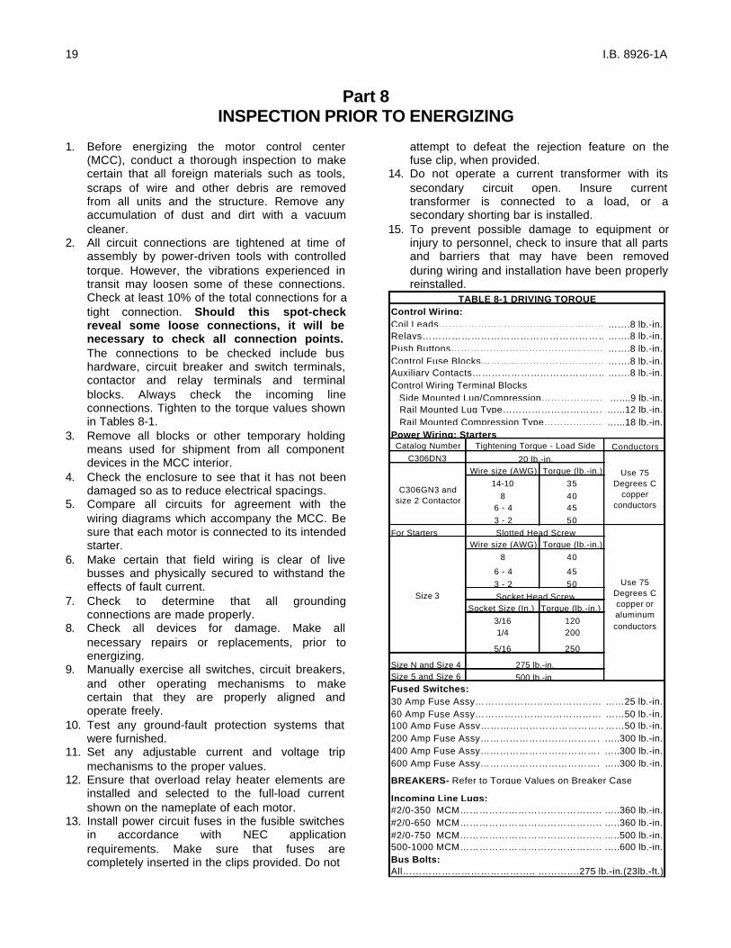
2. All circuit connections are tightened at time ofassembly by power-driven tools with controlledtorque. However, the vibrations experienced intransit may loosen some of these connections.Check at least 10% of the total connections for atight connection. Should this spot-checkreveal some loose connections, it will benecessary to check all connection points.The connections to be checked include bushardware, circuit breaker and switch terminals,contactor and relay terminals and terminalblocks. Always check the incoming lineconnections. Tighten to the torque values shownin Tables 8-1.
3. Remove all blocks or other temporary holdingmeans used for shipment from all componentdevices in the MCC interior.
4. Check the enclosure to see that it has not beendamaged so as to reduce electrical spacings.
5. Compare all circuits for agreement with thewiring diagrams which accompany the MCC. Besure that each motor is connected to its intendedstarter.
6. Make certain that field wiring is clear of livebusses and physically secured to withstand theeffects of fault current.
7. Check to determine that all groundingconnections are made properly.
8. Check all devices for damage. Make allnecessary repairs or replacements, prior toenergizing.
9. Manually exercise all switches, circuit breakers,and other operating mechanisms to makecertain that they are properly aligned andoperate freely.
10. Test any ground-fault protection systems thatwere furnished.
11. Set any adjustable current and voltage tripmechanisms to the proper values.
12. Ensure that overload relay heater elements areinstalled and selected to the full-load currentshown on the nameplate of each motor.
13. Install power circuit fuses in the fusible switchesin accordance with NEC applicationrequirements. Make sure that fuses arecompletely inserted in the clips provided. Do not
attempt to defeat the rejection feature on thefuse clip, when provided.
14. Do not operate a current transformer with itssecondary circuit open. Insure currenttransformer is connected to a load, or asecondary shorting bar is installed.
15. To prevent possible damage to equipment orinjury to personnel, check to insure that all partsand barriers that may have been removedduring wiring and installation have been properlyreinstalled.
Coil Leads…………………………………………….…….8 lb.-in.Relays………………………………………………………….8 lb.-in.Push Buttons……………………………………….. …….8 lb.-in.Control Fuse Blocks………………………………………….8 lb.-in.Auxiliary Contacts………………………………………….8 lb.-in.Control Wiring Terminal Blocks Side Mounted Lug/Compression……………………....9 lb.-in. Rail Mounted Lug Type…………………………….…...12 lb.-in. Rail Mounted Compression Type………………….…...18 lb.-in.
Using Overload Catalog Number Conductors
C306DN3Wire size (AWG) Torque (lb.-in.)
14-10 358 40
6 - 4 453 - 2 50
For StartersWire size (AWG) Torque (lb.-in.)
8 40
6 - 4 453 - 2 50
Socket Size (In.) Torque (lb.-in.)3/16 1201/4 200
5/16 250
Size N and Size 4Size 5 and Size 6
30 Amp Fuse Assy………………………………… ……25 lb.-in.60 Amp Fuse Assy………………………………… ……50 lb.-in.100 Amp Fuse Assy………………………………………50 lb.-in.200 Amp Fuse Assy………………………………. …..300 lb.-in.400 Amp Fuse Assy………………………………. …..300 lb.-in.600 Amp Fuse Assy………………………………. …..300 lb.-in.
#2/0-350 MCM…………………………………….. …..360 lb.-in.#2/0-650 MCM…………………………………….. …..360 lb.-in.#2/0-750 MCM…………………………………….. …..500 lb.-in.500-1000 MCM…………………………………….. …..600 lb.-in.
All………………………………….. ………….275 lb.-in.(23lb.-ft.)
20 lb.-in.
BREAKERS- Refer to Torque Values on Breaker Case
Incoming Line Lugs:
Bus Bolts:
Size 3 Socket Head Screw
275 lb.-in.500 lb.-in.
Use 75 Degrees C copper or aluminum conductors
Slotted Head Screw
Fused Switches:
TABLE 8-1 DRIVING TORQUEControl Wiring:
Power Wiring: Starters
C306GN3 and size 2 Contactor
Tightening Torque - Load Side
Use 75 Degrees C
copper conductors

20 I.B. 8926-1A
16. Conduct an electrical insulation resistance test tomake sure that the MCC and field wiring are freefrom short circuits and grounds. Do this testphase-to-phase, phase-to-ground, and phase-to-neutral, with the switches or circuit breakersopened.
17. If the MCC contains a labyrinth vertical busbarrier system, verify the operation of the
automatic shutters. See Part 9 for adjustmentsof this mechanism.
18. Install covers, close doors, and make certain thatno wires are pinched and that all enclosure partsare properly aligned and tightened.
19. Turn all circuit breakers and fusible switches tothe OFF position before energizing the bus.
Part 9UNIT INSTALLATION AND ADJUSTMENT
DOOR REMOVAL AND INSTALLATION
All doors on the control center are mounted on pinhinges to facilitate removal for installation andmaintenance operations. With the operating handleon the OFF position, rotate the quarter-turn latches,open the door, remove the hinge pins as shown inFigure 26, partially close the door and lift it from thestructure. Reverse this procedure for installation.
UNIT REMOVAL AND INSTALLATION
After opening and/or removing the unit door, thecontrol unit is exposed. With a screwdriver, push inon the latch at the top center of the unit and rotate ¼turn counterclockwise. CAUTION: Units 18” or morehigh have a retaining brace at the lower edge ofeach side of the unit frame to add stability inshipping. The shipping braces may be retained orremoved after installation; unscrew prior to unitwithdrawal. Pull-apart terminal blocks in the verticalwireway must be disengaged (see Figure 27 andpage 10) and wiring from the unit to other units, tomaster terminal blocks or to load devices must bedisconnected before the unit is removed. Grasp theunit as shown in Figure 28 and pull it outward. Thefirst inch of travel pulls the stabs free from thevertical bus, and the grounding clip on the side ofthe unit frame is also disengaged.
To replace a control unit, position the mountingpoints on the unit frame with the mating guide rails.Slide the unit inward until all four mounting pointsare engaged, then move it inward with a quick push.This movement easily overcomes the compressionof the stabs as they engage the vertical bus. Withthe unit in its correct position, the quarter-turn latchis easily engaged by pushing inward and rotating ¼turn clockwise.
Fig.26 Hinge Pin Removal
Fig. 27 Disengaging Pull-Apart Terminal Blocks
Fig. 28 Withdrawing a Unit

21 I.B. 8926-1A
DETENT POSITION
For maintenance and test purposes, the unit can bepartially withdrawn (approximately 1 ½ inches) untilthe stabs are free of the bus. In this position, thequarter-turn latch can be rotated clockwise toengage the detent position slot; this will secure theunit to ensure the stabs remain disengaged duringmaintenance. See Figure 29. The latch can bepadlocked in this position.
OPERATING HANDLE LINKAGEADJUSTMENT
Movement of the operating handle in the verticalplane should not be restricted by the handle cavity ateither the top or bottom to its travel. Shouldrestriction occur, eliminate it adjusting the length ofthe operating linkage as shown in Figure 30.Depending on the type of primary disconnect devicecontained in the control unit, it may be necessary tolengthen or shorten the linkage.
AUTOMATIC SHUTTER TRAVELADJUSTMENT
When the optional labyrinth vertical bus barrier isinstalled in the control center, a shutter is providedto automatically cover the stab openings when acontrol unit is withdrawn. The shutter is opened byengagement of the left-hand side of the control unitwith the shutter arm linkage attached to the left-handvertical structural members. When the unit iswithdrawn free of the linkage, a spring automaticallymoves the shutter to its closed position. See Figure31 and Figure 4.
With the control unit removed, the shutter shouldcompletely cover the stab openings. If it does notcover the openings, use an adjustable wrench tobend the link arm to the right until the shutter coversthe stab openings.
If, on re-insertion of the control unit, interference isfelt between the stab assembly at the rear of the unitand the shutter, the engagement of the control unitwith the shutter arm linkage is insufficient to fullyopen the shutter. Use an adjustable wrench to bendthe linkage arm inward toward the unit to increase itsengagement with the unit. An inward bend ofapproximately ¼ inch will provide sufficientadditional shutter travel.
INSTALLING PILOT DEVICES
The device panel can accommodate up to six pilotdevices such as oil-tight pushbuttons, indicating
lights, selector switches and miniature meters. Ifunused space is available and the addition of otherdevices is desired, observe the following procedure.
After opening the unit door, loosen the two screws atthe top of the device panel. Slide the panel ½ inchleft to permit it to swing down for access. See Figure32. With the peen end of a ball-peen hammer or witha drift or chisel, remove the desired knockout.
Fig. 29 Unit Locked in Detent Position
Fig. 30 Operating Handle Linkage Adjustment
Fig. 31 Shutter Arm Linkage

22 I.B. 8926-1A
CAUTION: Brace the panel solidly to avoid breakingthe hinge points. Use a knife or small file to removeremaining plastic burrs. Install and wire the newdevice and re-attach the top of the device panel tothe unit.
Fig. 32 Unit Device Panel
INSTALLING A NEW UNIT
It is recommended that a new unit be installed in aunit space at the top of a vertical compartment ordirectly below an existing unit. Material provided withthe new unit by the factory includes: A divider panwith integral guide rails, a unit door, hinges, catchesand hardware. Observe the following sequence ofoperations for installation.
1. Remove the existing blank door.2. Position the new unit door over the open space
to ensure the hinges and latches are aligned. Ifthe spaces differ, the hinges and latches on thestructure must be re-located to match the unitdoor hinges and latches. Mount the door, usingthe hinge pins provided.
3. Install the new divider pan in the notchesprovided in the rear barrier so that it is alignedwith the bottom of the new door. Attach the panto the vertical structure channels with onethread-forming screw on each side.
4. Remove from the vertical bus barrier the flatplate which covers the stab holes that will alignwith the stabs on the new unit. If an optionallabyrinth vertical bus barrier is in place, install anautomatic shutter over the stab cutouts. Followthe instruction sheet provided with the shutterkit.
23 I.B. 8926-1A
Part 10MAINTENANCE
PREVENTIVE MAINTENANCE
Preventive maintenance should be a program, ascheduled periodic action that begins with theinstallation of the equipment. At that time, specificmanufacturer’s instruction literature should beconsulted, then stored for future reference. Follow-upmaintenance should be at regular intervals, asfrequently as the severity of duty justifies. Timeintervals of one week, or one month, or one yearmay be appropriate, depending on the duty. It is alsodesirable to establish specific check lists for eachcontrol, as well as a logbook to record the history ofincidents. A supply of renewal parts should beobtained and stored.
This control equipment is designed to be installed,operated, and maintained by adequately trainedworkmen. These instructions do not cover all details,variations, or combinations of the equipment, itsstorage, delivery, installation, check-out, safeoperation, or maintenance. Care must be exercisedto comply with local, state, and national regulations,as well as safety practices, for this class ofequipment.
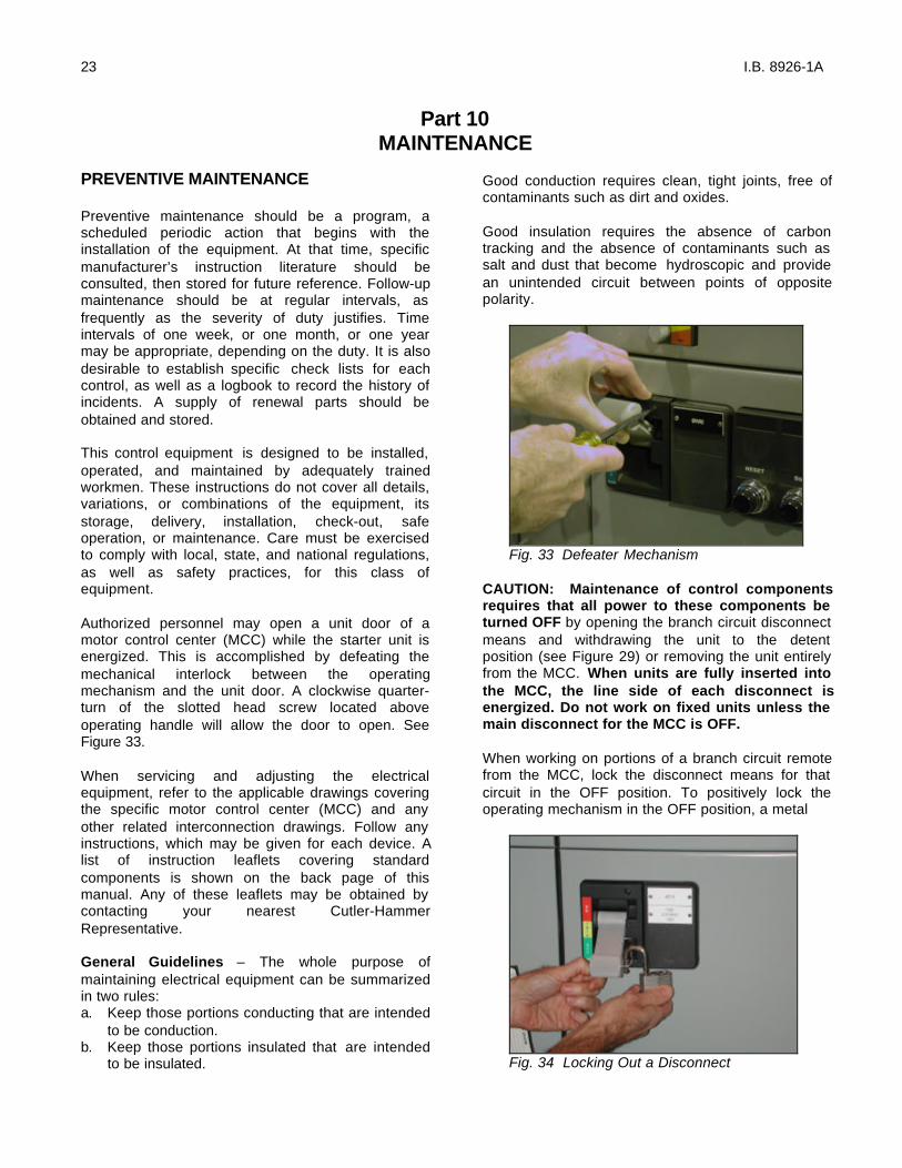
Authorized personnel may open a unit door of amotor control center (MCC) while the starter unit isenergized. This is accomplished by defeating themechanical interlock between the operatingmechanism and the unit door. A clockwise quarter-turn of the slotted head screw located aboveoperating handle will allow the door to open. SeeFigure 33.
When servicing and adjusting the electricalequipment, refer to the applicable drawings coveringthe specific motor control center (MCC) and anyother related interconnection drawings. Follow anyinstructions, which may be given for each device. Alist of instruction leaflets covering standardcomponents is shown on the back page of thismanual. Any of these leaflets may be obtained bycontacting your nearest Cutler-HammerRepresentative.
General Guidelines – The whole purpose ofmaintaining electrical equipment can be summarizedin two rules:a. Keep those portions conducting that are intended
to be conduction.b. Keep those portions insulated that are intended
to be insulated.
Good conduction requires clean, tight joints, free ofcontaminants such as dirt and oxides.
Good insulation requires the absence of carbontracking and the absence of contaminants such assalt and dust that become hydroscopic and providean unintended circuit between points of oppositepolarity.
Fig. 33 Defeater Mechanism
CAUTION: Maintenance of control componentsrequires that all power to these components beturned OFF by opening the branch circuit disconnectmeans and withdrawing the unit to the detentposition (see Figure 29) or removing the unit entirelyfrom the MCC. When units are fully inserted intothe MCC, the line side of each disconnect isenergized. Do not work on fixed units unless themain disconnect for the MCC is OFF.
When working on portions of a branch circuit remotefrom the MCC, lock the disconnect means for thatcircuit in the OFF position. To positively lock theoperating mechanism in the OFF position, a metal
Fig. 34 Locking Out a Disconnect

24 I.B. 8926-1A
locking bar recessed in the handle may be extendedand padlocked with from one to three padlocks. SeeFigure 34.
With the door open and the disconnect device OFF,the operating handle is mechanically interlocked toprevent inadvertently being pushed ON. To defeatthis interlock, the bar on the top of the mechanismshould be pushed in slightly, allowing the handle tomove upward to the ON position. WARNING: IFFULLY INSERTED, THE POWER AND CONTROLCITCUITS WILL BE ENERGIZED. Padlocking toprevent this handle movement may be accomplishedby the same method as described above.
Separate control sources of power must also bedisconnected. If control power is used duringmaintenance, take steps to prevent feedback of ahazardous voltage through a controltransformer. Be alert to power factor correctioncapacitors that may be charged. Discharge thembefore working on any part of the associatedpower circuit.
Cleaning. Soot, smoke, or stained areas (other thaninside arc chutes), or other unusual deposits, shouldbe investigated and the source determined beforecleaning is undertaken. Vacuum or wipe clean allexposed surfaces of the control component and theinside of its enclosure. Equipment may be blownclean with compressed air that is dry and free fromoil. (Be alert to built-in oilers in factory compressedair lines!) If air blowing techniques are used, removearc covers from contactors and seal openings tocontrol circuit contacts that are present. It isessential that the foreign debris be removed fromthe control center, not merely rearranged. Controlequipment should be clean and dry. Remove dustand dirt inside and outside the cabinet without usingliquid cleaner. Remove foreign material from theoutside top and inside bottom of the enclosure,including hardware and debris, so that futureexamination will reveal any parts that have fallen offor dropped onto the equipment. If there are liquidsspread inside, determine the source and correct bysealing conduit, adding space heaters, or otheraction as applicable.
Mechanical checks. Tighten all electricalconnections. Look for signs of overheated joints,charred insulation, discolored terminals, etc.Mechanically clean to a bright finish (don’t useemery paper) or replace those terminations thathave become discolored. Determine the cause ofthe loose joint and correct. Be particularly carefulwith aluminum wire connections. Aluminum wire isbest terminated with a crimp type lug that is attached
to the control component. When screw type lugs(marked CU/AL) are used with aluminum wire, jointshould be checked for tightness every 200operations of the device.
Wires and cables should be examined to eliminateany chafing against metal edges caused byvibration, that could progress to an insulation failure.Any temporary wiring should be removed, orpermanently secured and diagrams markedaccordingly.
The intended movement of mechanical parts, suchas the armature and contacts of electromechanicalcontactors, and mechanical interlocks should bechecked for freedom of motion and functionaloperation.
Wrap-up. Check all indicating lamps, mechanicalflags, doors, latches, and similar auxiliaries andrepair, if required.
Log changes and observations into record bookbefore returning equipment into service. Do notremove any labels or nameplates. Restore any thatare damaged.
SLIDER OPERATOR MECHANISM –(6 Inch Units) (See Figure 35)
The following features are found on 6-inch units withcircuit breaker operators.A. Door Interlock
The operator mechanism is factory adjusted andnormally does not need field adjustment. Thedoor interlock mechanism engages a hook thatis mounted to the welded bracket. This allowsthe unit door to open when the operator handleis in the “off” (right) position. With the handle inthe “on” (left) position, the door is interlockedand should not open. If the door hook and themechanism do not engage properly, thepositioning of the door hook on the bracket mayneed adjustment. The door hook can beadjusted left or right by loosening the screw (seephotograph). After adjustment, tighten screw to20 lb.-in. [2.2 N•m]. See Figure 38 insert.
B. Defeater ScrewTurning the defeater screw clockwise allows youto open the unit door (access to the panelmounted components) with the operator handle(padlocked or not) in the “on” (left) position.
C. Padlocking (See Figures 36, & 37)The operator handle can be padlocked in the“off” position with up to three 3/8” [19.5 mm](Max.) shank padlocks.

25 I.B. 8926-1A
To provide for padlocking the circuit breakeroperator in the “on” position, drill the appropriatesize hole through the drill point located on theoperator mechanism.
D. Unit InterlockThe unit interlock is provided to assure that theunit circuit breaker is:- Open before the stab clips can contact the
vertical bus.
- Open before the stab clips can be disengagedfrom the vertical bus.
The unit interlock and bracket does not need fieldadjustment. The interlock bracket will be adjusted toalmost touch the side of the unit interlock rod whenthe operator is in the “on” position.
Fig. 35 6-Inch Breaker Unit Slider Operator MechanismMCC Slider Operator Mechanism Padlocking
Fig. 36(A) Rectangular slot for scissors.(B) One 1/4 in. or 5/16 in. diameter padlock hasp.
Fig. 37(C) Rotate lock plate for one to three 3/8 in.
diameter padlock hasp locks.
DOOR INTERLOCKDOOR INTERLOCK HOOK(6 Inch Units)
UNIT INTERLOCK(ROD)
DEFEATER SCREW
ON PADLOCK AREA
OFF POSITION (RIGHT)
OFF PADLOCKS
ON POSITION (LEFT)
(A)
(B)
30-150 AMP30-150 AMP
ON ONLock Plate(C)

26 I.B. 8926-1A
CONTACT WEAR AND REPLACEMENT
Contactors are subject to both mechanical andelectrical wear during their operation. In most casesmechanical wear is insignificant. The erosion of thecontacts is due to electrical wear. During arcing,material from each contact is vaporized and blownaway from the useful contacting surface.
A critical examination of the appearance of thecontact surfaces and a measurement of theremaining contact over-travel will give the user theinformation required to get the maximum contact life.
OVER-TRAVEL MEASUREMENT
Contact life has ended when the over-travel of thecontacts has been reduced to .020 inch.
Over-travel of the contact assembly is that part ofthe stroke which the moving contacts would travelafter touching the fixed contacts if they were notblocked from movement by the fixed contacts.
A method of measuring over-travel is as follows:A. Place a .020 inch feeler gauge between the
armature and magnet, with the armature heldtightly against the magnet.
B. Check continually in each phase, i.e.,determine if circuit from terminal-to-terminal foreach pole is open under these conditions.
C. If there is continuity through all phases, theremaining over-travel is sufficient. If there is notcontinuity through all phases, replace allstationary and moving contacts plus movingcontact over-travel springs. After replacingparts, manually operate contactor to be surebinding does not occur.
DEFECT CAUSE REMEDYShort contact life
Low contact force
Adjust overtravel, replace contacts, and replace contact springs as required to correct contact force.
Contact bounce on opening or closing
Correct improper voltage applied to coil. Correct any mechanical defects or misalignment.
Abrasive dust on contacts
Do not use emery cloth to dress contacts.
Load current is too high
Reduce load. Use larger contactor.
Jogging cycle is too severe
Reduce jogging cycle. Check factory for more durable contact material. Use larger contactor.
CONTACTOR TROUBLESHOOTING CHART
DEFECT CAUSE REMEDYOverheating Load current
too highReduce load. Use larger contactor.
Loose connections
Clean discolored or dirty connections and retighten. Replace poorly crimped lugs.
Over-travel and/or contact force too low
Adjust over-travel, replace contacts, and replace contact springs as required to correct defect.
Ambient temperature is too high
Reduce load. Provide better ventilation. Relocate starter. Use larger contactor.
Line and/or load cables are too small
Install terminal block and run larger conductors between contactor and terminal block.
CONTACTOR TROUBLESHOOTING CHART
Welding of contacts
Overtravel and/or contact force is too low
Adjust overtravel, replace contacts, and replace contact springs as required to correct contact force.
Magnet armature stalls or hesitates at contact touch point
Correct low voltage at coil terminals as coil draws inrush current.
Contactor drops open to contact-touch position because of voltage dip
Maintain voltage at coil terminals. Install low voltage protective device, sometimes called "Brownout Protector".
Excessive contact bounce on closing
Correct coil overvoltage condition.
MAINTENANCE OF MOTOR CONTROLLERSAFTER A FAULT=
In a motor branch circuit which has been properlyinstalled, coordinated and in service prior to thefault, opening of the branch-circuit short-circuitprotective device (fuse, circuit breaker, motor short-circuit protector, etc.) indicates a fault condition inexcess of operating overload. This fault conditionmust be corrected and the necessary repair or

27 I.B. 8926-1A
= Reproduced by permission of the National Electrical Manufacturers Association from NEMA Standards Publication No. ICS 2-1978 (R1983), Industrial Control Devices, Controllers and Assemblies, copyright 1978 by NEMA.replacements made before re-energizing the branchcircuit.
It is recommended that the following generalprocedures be observed by qualified personnel inthe inspection and repair of the motor controllerinvolved in the fault.
Procedure – Caution: All inspections and testsare to be made on controllers and equipmentwhich are de-energized, disconnected andisolated so that accidental contact cannot bemade with live parts and so that all plant safetyprocedures will be observed.
Enclosure. Substantial damage to the unit door orframe such as deformation, displacement of parts orburning, requires replacement of the entire unit.
Circuit breaker. Examine the unit interior and thecircuit breaker for evidence of possible damage. Ifevidence of damage is not apparent, the breakermay be reset and turned ON. If it is suspected thatthe circuit breaker has opened several short-circuitfaults or if signs of circuit breaker deteriorationappear within the enclosure, the circuit breakershould be replaced.
Disconnect switch. The external operating handleof the disconnect switch must be capable of openingthe switch. If the handle fails to open the switch or ifvisual inspection after opening indicatesdeterioration beyond normal wear and tear, such asoverheating, contact blade or jaw pitting, insulationbreakage or charring, the switch must be replaced.
Fuse holders. Deterioration of fuse holders or theirinsulating mounts requires their replacement.
Terminals and internal conductors. Indications ofarcing damage and/or overheating such asdiscoloration and melting of insulation require thereplacement of damaged parts.
Contactor. Contacts showing heat damage,displacement of metal, or loss of adequate wearallowance require replacement of the contacts andthe contact springs. If deterioration extends beyondthe contacts, such as binding in the guides orevidence of insulation damage, the damaged partsor the entire contactor must be replaced.
Overload relays. If burnout of the current elementof an overload relay has occurred, the completeoverload relay must be replaced. Any indication thatan arc has struck and/or any indication of burning ofthe insulation of the overload relay also requiresreplacement of the overload relay.
If there is no visual indication of damage that wouldrequire replacement of the overload relay, the relaymust be electrically or mechanically tripped to verifythe proper functioning of the overload relaycontact(s).
Return to service. Before returning the controller toservice, checks must be made for the tightness ofelectrical connections and for the absence of shortcircuits, grounds an leakage.
All equipment enclosures must be closed andsecured before the branch circuit is energized.
Fig. 39 Normal Service Wear
Fig. 40 End of Service Life

28 I.B. 8926-1A
Time of Service Contact Appearance
New The new contact has a uniform silver color.
Start of Service The contact surface will have a blue coloring. The geometric form of the contact is unchanged. The sharp outer corners will be rounded with small silver beads. (See Figure 39).
Intermediate Service to End of Service Life
The coloring changes to brown or black with distributed small silvery white areas. The surface has a finely chiselled appearance. Material transfer causes small peaks and valleys in the contact button surface. (See Figure 40).
CONTACT EVALUATION
Contact Appearance Cause
Curling and Separation of Corner of Contact
Curling is usually a result of service that produces very high heat, as under jogging or inching duty.
Irregular Contour or Slantwise Wear
One corner of a contact may wear more quickly than the other three corners. This wear is normally due to misalignment of the moving and stationary contacts. Contacts should be replaced if it is apparent that one contact is nearly making direct contact with the contact carrier.
Large Beads of Silver On Edges of Contacts
Breaking an excessive current.
Welded Spot (Core of Smooth, Shining Silver Surrounded by a Roughened Halo)
Making an excessive current. High frequency of operation, i.e., jogging.
ABNORMAL WEAR CONDITIONS
RENEWAL PARTS
When ordering renewal control center parts, give thecomplete nameplate reading. Always give the nameof the part wanted, the part, catalog or style numberof the individual apparatus on which it is to be used,and the order number of the complete motor controlcenter.
Control Center renewal parts identified by part orstyle number are detailed in Cutler-HammerRenewal Parts Data. The nomenclature to identifythese parts is shown in Figures 2 and 41. The mostcommon renewal parts for components are shown inTable10-1.

29 I.B. 8926-1A
NEMA SIZE 1 Series B1
NEMA SIZE 2 Series B1
NEMA SIZE 3 NEMA SIZE 4 NEMA SIZE 5 Series B1
Part No. Part No. Part No. Part No. Part No.22177 22177 20426 20428 20429
6-65 6-65-7 6-43-5 6-44 6-456-65-2 6-65-8 6-43-6 6-44-2 6-45-26-65-9 6-65-15 --------- --------- ---------6-65-10 6-65-16 --------- --------- ---------
MAGNET COILS Coil Suffix
120V 60 Hz or 110V 50 Hz A 9-2703-1 9-2703-1 9-2756-1 9-1891-1 9-1891-1240V 60 Hz or 220V 50 Hz B 9-2703-2 9-2703-2 9-2756-2 9-1891-2 9-1891-2480V 60 Hz or 440V 50 Hz C 9-2703-3 9-2703-3 9-2756-3 9-1891-3 9-1891-3600V 60 Hz or 550V 50 Hz D 9-2703-4 9-2703-4 9-2756-4 9-1891-4 9-1891-4
208V 60 Hz……………….. E 9-2703-9 9-2703-9 9-2756-5 9-1891-13 9-1891-13277V 60 Hz……………….. H 9-2703-7 9-2703-7 9-2756-9 9-1891-26 9-1891-26208/240V 60 Hz………….. J ------------ ------------ ------------ ------------ ------------240V 50 Hz……………….. K 9-2703-14 9-2703-14 9-2756-13 9-1891-20 9-1891-20380-415V 50 Hz………….. L 9-2703-8 9-2703-8 ------------ ------------ ------------
380V 50 Hz……………….. L ------------ ------------ 9-2756-12 9-1891-14 9-1891-14415V 50 Hz……………….. M ------------ ------------ 9-2756-8 9-1891-21 9-1891-21550V 50 Hz……………….. N ------------ ------------ 9-2756-14 9-1891-8 9-1891-8
C306KN3 C306NN3 C306DN3B
TABLE 10-1 RENEWAL CONTACT KITS, COILS & OVERLOAD RELAYS
OVERLOAD RELAYS
C306GN3B C306GN3B
2 Pole…………………………3 Pole…………………………
Description
For replacement on existing starters 3 Pole - Ambient Compensated Bimetallic……
4 Pole…………………………5 Pole…………………………
Renewal Parts Publ.CONTACT KITS
STARTER TYPE
Description
Disconnect Means:
Fusible Circuit Breaker
Circuit Breaker With Current Limiter
F204 F206 F207F214 F216 F217F604 F606 F607F704 F706 F707F894 F896 F897F954 F956 F957F944 F946 F947
Unit Catalog Number Designation (Class)
Reduced Voltage, Part Winding TypeReduced Voltage, Autotransformer TypeFull Voltage, Reversing
Reduced Voltage, Closed Transition Star-DeltaFull Voltage, Non-Reversing, 2 Speed, 2 WindingsFull Voltage, Non-Reversing, 2 Speed, 1 Winding
Full Voltage, Non-Reversing

30 I.B. 8926-1A
Fig. 41 Control Center Unit Nomenclature
Unit Disconnect Device(7)
(6)Unit Guides(Included withItem 3)
(5)Quarter TurnLatch(Included inItem 9)
(4)Freedom Starter
(3)Unit Frame
(2)Heater Mounts
(1)
(8)Stab Assembly
(9)Unit Drawout
Handle
(10)Unit Terminal
Blocks
(11)Control Power
Transformerwith Fuses
(12)
Pivot Tube
(13)Device Panel
Operating Handle
(14)Pilot Devices

31 I.B. 8926-1A
Part 11PLAN VIEWS

32 I.B. 8926-1A
20 Inches Wide, 16 Inches DeepFront Mounted Only (4710A30)
20 Inches Wide, 21 Inches DeepFront Mounted Only (4710A31)
24 Inches Wide, 16 Inches DeepFront Mounted Only (4710A33)
24 Inches Wide, 21 Inches DeepFront Mounted Only (4710A34)
1. Minimum length of anchor bolt is 2.00". (.38-16 grade 5 torqued at 31lb-ft).A. For non seismic, mount with 2 center bolts per enclosure.B. For seismic, mount with min 4 corner bolts per enclosure.2. Recommended maximum conduit height above floor line is 3.50 inches.3. Maximum conduit space with channel sills is 17.50 X 9.73 inches.4. For multiple structure assemblies either one or both of these members are removed to providemaximum unrestricted conduit space at the bottom of the MCC.5. This conduit space is not recommended when a neutral bus is required. Otherwise available.
See side View A. far right for vertical dimensions

33 I.B. 8926-1A
20 Inches Wide, 21 Inches DeepFront and Rear Mounted (4710A32)
10 Inches Wide, 16 or 21 Inches DeepTransition Structure (4710A35/6)
SIDE VIEW B
Common Notes
7. Master Terminal Block assembly is furnished for type Type C wiring only when locationnot specified. MTB supplied at the bottom.
8. Rear horizontal bus barrier not supplied with front mounted only structure.9. Standard structure arrangement
(a) In FrontWithout MTB: A & B = 9”With MTB at bottom: A & B = 9”With MTB at top: A & B = 3”(b) In RearWithout MTB: C = 0, D = 72”, E = 3”With MTB at bottom: C = 0, D = 66”, E = 9”With MTB at top C = 12, D = 60”, E = 3”
1. Minimum length of anchor bolt is 2.00". (.38-16 grade 5 torqued at 31lb-ft).A. For non seismic, mount with 2 center bolts per enclosure.B. For seismic, mount with min 4 corner bolts per enclosure.2. Recommended maximum conduit height above floor line is 3.50 inches.3. Maximum conduit space with channel sills is 17.50 X 9.73 inches.4. For multiple structure assemblies either one or both of these members are removed to providemaximum unrestricted conduit space at the bottom of the MCC.5. This conduit space is not recommended when a neutral bus is required. Otherwise available.
See side View B. far right for vertical dimensions
1. Minimum length of anchor bolt is 2.00". (.38-16 grade 5 torqued at 31lb-ft).A. For non seismic, mount with 2 center bolts per enclosure.B. For seismic, mount with min 4 corner bolts per enclosure.2. Recommended maximum conduit height above floor line is 3.50 inches.3. Maximum conduit space with channel sills is 17.50 X 9.73 inches.4. For multiple structure assemblies either one or both of these members are removed to providemaximum unrestricted conduit space at the bottom of the MCC.5. This conduit space is not recommended when a neutral bus is required. Otherwise available.
SIDE VIEW A
SIDE VIEWS

34 I.B. 8926-1A
RELATED INSTRUCTION LEAFLETS
Starters:Size 5, Non-Reversing and Reversing, vacuum.………………………….I.L. 17087Size 6, Non-Reversing and Reversing, vacuum .…………………………I.L. 17089
Contactors:Size 5, Non-Reversing and Reversing, vacuum...………………………..I.L. 16999Size 5, Non-Reversing and Reversing, vacuum...………………………..I.L. 17088
Circuit Breakers:Series C, F-frame…………………………………………………………..I.L. 29C101Series C, J-frame…………………………………………………………..I.L. 29C103Series C, K-frame…………………………………………………………. I.L. 29C104Series C, L-frame…………………………………………………………. I.L. 29C105Series C, N-frame…………………………………………………………..I.L. 29C106Series C, R-frame………………………………………………………….I.L. 29C107Transfer Switches…………………………………………………………… I.L. 14477
I.B. 8926-1A Cutler-Hammer, Inc. Printed in USAEffective 3/01 Fayetteville, N.C. U.S.A 28306


![PROCUREMENT SPECIFICATION - Rockwell Automation · [PROJECT NUMBER] [PROJECT NAME] [DATE] [PROJECT LOCATION] CENTERLINE 2100 Motor Control Centers Rockwell Automation 2100-SR007K-EN-E](https://img.pdfslide.net/doc/110x75/5e15ff04c0b8380fd7152cb0/procurement-specification-rockwell-automation-project-number-project-name.jpg)