Embed Size (px)
Citation preview

Document Number: TTUGRev. 1.607/2011
Freescale Test ToolUser’s Guide
How to Reach Us:
Home Page:www.freescale.com
E-mail:[email protected]
USA/Europe or Locations Not Listed:Freescale SemiconductorTechnical Information Center, CH3701300 N. Alma School RoadChandler, Arizona 85224+1-800-521-6274 or [email protected]
Europe, Middle East, and Africa:Freescale Halbleiter Deutschland GmbHTechnical Information CenterSchatzbogen 781829 Muenchen, Germany+44 1296 380 456 (English)+46 8 52200080 (English)+49 89 92103 559 (German)+33 1 69 35 48 48 (French)[email protected]
Japan:Freescale Semiconductor Japan Ltd.HeadquartersARCO Tower 15F1-8-1, Shimo-Meguro, Meguro-ku,Tokyo 153-0064, Japan0120 191014 or +81 3 5437 [email protected]
Asia/Pacific:Freescale Semiconductor Hong Kong Ltd.Technical Information Center2 Dai King StreetTai Po Industrial EstateTai Po, N.T., Hong Kong+800 2666 [email protected]
For Literature Requests Only:Freescale Semiconductor Literature Distribution CenterP.O. Box 5405Denver, Colorado 802171-800-521-6274 or 303-675-2140Fax: [email protected]
Information in this document is provided solely to enable system and software implementers to use Freescale Semiconductor products. There are no express or implied copyright licenses granted hereunder to design or fabricate any integrated circuits or integrated circuits based on the information in this document.Freescale Semiconductor reserves the right to make changes without further notice to any products herein. Freescale Semiconductor makes no warranty, representation or guarantee regarding the suitability of its products for any particular purpose, nor does Freescale Semiconductor assume any liability arising out of the application or use of any product or circuit, and specifically disclaims any and all liability, including without limitation consequential or incidental damages. “Typical” parameters that may be provided in Freescale Semiconductor data sheets and/or specifications can and do vary in different applications and actual performance may vary over time. All operating parameters, including “Typicals”, must be validated for each customer application by customer’s technical experts. Freescale Semiconductor does not convey any license under its patent rights nor the rights of others. Freescale Semiconductor products are not designed, intended, or authorized for use as components in systems intended for surgical implant into the body, or other applications intended to support or sustain life, or for any other application in which the failure of the Freescale Semiconductor product could create a situation where personal injury or death may occur. Should Buyer purchase or use Freescale Semiconductor products for any such unintended or unauthorized application, Buyer shall indemnify and hold Freescale Semiconductor and its officers, employees, subsidiaries, affiliates, and distributors harmless against all claims, costs, damages, and expenses, and reasonable attorney fees arising out of, directly or indirectly, any claim of personal injury or death associated with such unintended or unauthorized use, even if such claim alleges that Freescale Semiconductor was negligent regarding the design or manufacture of the part.
Freescale and the Freescale logo are trademarks or registered trademarks of Freescale Semiconductor, Inc. in the U.S. and other countries. All other product or service names are the property of their respective owners. ARM is the registered trademark of ARM Limited. ARM7TDMI-S is the trademark of ARM Limited.© Freescale Semiconductor, Inc. 2007, 2008, 2009, 2010, 2011
Freescale Test Tool User’s Guide, Rev. 1.6
Freescale Semiconductor i
ContentsAbout This Book
Audience . . . . . . . . . . . . . . . . . . . . . . . . . . . . . . . . . . . . . . . . . . . . . . . . . . . . . . . . . . . . . . . . . . . . . vOrganization . . . . . . . . . . . . . . . . . . . . . . . . . . . . . . . . . . . . . . . . . . . . . . . . . . . . . . . . . . . . . . . . . . vRevision History . . . . . . . . . . . . . . . . . . . . . . . . . . . . . . . . . . . . . . . . . . . . . . . . . . . . . . . . . . . . . . viConventions . . . . . . . . . . . . . . . . . . . . . . . . . . . . . . . . . . . . . . . . . . . . . . . . . . . . . . . . . . . . . . . . . viDefinitions, Acronyms, and Abbreviations . . . . . . . . . . . . . . . . . . . . . . . . . . . . . . . . . . . . . . . . . vi
Chapter 1 Introduction
1.1 Installing the Test Tool Software . . . . . . . . . . . . . . . . . . . . . . . . . . . . . . . . . . . . . . . . . . . . . . . . 1-21.2 Test Tool Interface Overview . . . . . . . . . . . . . . . . . . . . . . . . . . . . . . . . . . . . . . . . . . . . . . . . . . . 1-51.2.1 Using the Test Tool Tool Bar . . . . . . . . . . . . . . . . . . . . . . . . . . . . . . . . . . . . . . . . . . . . . . . . 1-61.2.2 Using the Test Tool Start Page Dashboard. . . . . . . . . . . . . . . . . . . . . . . . . . . . . . . . . . . . . . 1-61.2.3 Test Tool Panels . . . . . . . . . . . . . . . . . . . . . . . . . . . . . . . . . . . . . . . . . . . . . . . . . . . . . . . . . . 1-81.2.4 Test Tool Settings . . . . . . . . . . . . . . . . . . . . . . . . . . . . . . . . . . . . . . . . . . . . . . . . . . . . . . . . 1-10
Chapter 2 Command Console
2.1 Command Console Hardware and Software Considerations . . . . . . . . . . . . . . . . . . . . . . . . . . . 2-12.2 Command Console Interface Overview . . . . . . . . . . . . . . . . . . . . . . . . . . . . . . . . . . . . . . . . . . . 2-22.3 Board Setup. . . . . . . . . . . . . . . . . . . . . . . . . . . . . . . . . . . . . . . . . . . . . . . . . . . . . . . . . . . . . . . . . 2-32.3.1 Configuring Serial Ports . . . . . . . . . . . . . . . . . . . . . . . . . . . . . . . . . . . . . . . . . . . . . . . . . . . . 2-62.4 Command Console Operation (802.15.4 MAC Applications) . . . . . . . . . . . . . . . . . . . . . . . . . . 2-82.4.1 Starting a MAC Coordinator and Associating a Device To It . . . . . . . . . . . . . . . . . . . . . . 2-112.5 Command Console Operation (ZigBee/BeeStack Applications) . . . . . . . . . . . . . . . . . . . . . . . 2-142.5.1 APS Layer Command Test . . . . . . . . . . . . . . . . . . . . . . . . . . . . . . . . . . . . . . . . . . . . . . . . . 2-142.5.2 .ZDO Test . . . . . . . . . . . . . . . . . . . . . . . . . . . . . . . . . . . . . . . . . . . . . . . . . . . . . . . . . . . . . . 2-172.5.3 TP2 Free Form Request Test . . . . . . . . . . . . . . . . . . . . . . . . . . . . . . . . . . . . . . . . . . . . . . . 2-202.5.4 Using Combo Devices . . . . . . . . . . . . . . . . . . . . . . . . . . . . . . . . . . . . . . . . . . . . . . . . . . . . 2-252.6 Command Console Interface Features . . . . . . . . . . . . . . . . . . . . . . . . . . . . . . . . . . . . . . . . . . . 2-352.6.1 Using the Command Set List . . . . . . . . . . . . . . . . . . . . . . . . . . . . . . . . . . . . . . . . . . . . . . . 2-352.6.2 Command Console Macros. . . . . . . . . . . . . . . . . . . . . . . . . . . . . . . . . . . . . . . . . . . . . . . . . 2-382.6.3 Rx/Tx Log Panel Options . . . . . . . . . . . . . . . . . . . . . . . . . . . . . . . . . . . . . . . . . . . . . . . . . . 2-40
Chapter 3 Script Server
3.1 Python Script Language . . . . . . . . . . . . . . . . . . . . . . . . . . . . . . . . . . . . . . . . . . . . . . . . . . . . . . . 3-13.2 Script Server Interface Overview . . . . . . . . . . . . . . . . . . . . . . . . . . . . . . . . . . . . . . . . . . . . . . . . 3-13.3 Loading and Executing Scripts . . . . . . . . . . . . . . . . . . . . . . . . . . . . . . . . . . . . . . . . . . . . . . . . . . 3-23.4 Adding a Script or Test Set. . . . . . . . . . . . . . . . . . . . . . . . . . . . . . . . . . . . . . . . . . . . . . . . . . . . . 3-43.5 Saving a Test Set. . . . . . . . . . . . . . . . . . . . . . . . . . . . . . . . . . . . . . . . . . . . . . . . . . . . . . . . . . . . . 3-53.6 Test Set (Remove All) . . . . . . . . . . . . . . . . . . . . . . . . . . . . . . . . . . . . . . . . . . . . . . . . . . . . . . . . 3-5
Freescale Test Tool User’s Guide, Rev. 1.6
ii Freescale Semiconductor
3.7 Editing a Test Set . . . . . . . . . . . . . . . . . . . . . . . . . . . . . . . . . . . . . . . . . . . . . . . . . . . . . . . . . . . . 3-63.8 Test Set Items . . . . . . . . . . . . . . . . . . . . . . . . . . . . . . . . . . . . . . . . . . . . . . . . . . . . . . . . . . . . . . . 3-63.8.1 Moving a Test Set Item. . . . . . . . . . . . . . . . . . . . . . . . . . . . . . . . . . . . . . . . . . . . . . . . . . . . . 3-63.8.2 Running a Single Test Set Script . . . . . . . . . . . . . . . . . . . . . . . . . . . . . . . . . . . . . . . . . . . . . 3-63.8.3 Deleting a Test Set Item . . . . . . . . . . . . . . . . . . . . . . . . . . . . . . . . . . . . . . . . . . . . . . . . . . . . 3-63.8.4 Search Path . . . . . . . . . . . . . . . . . . . . . . . . . . . . . . . . . . . . . . . . . . . . . . . . . . . . . . . . . . . . . . 3-63.8.5 Script Output and Results . . . . . . . . . . . . . . . . . . . . . . . . . . . . . . . . . . . . . . . . . . . . . . . . . . . 3-73.9 Python Scripts . . . . . . . . . . . . . . . . . . . . . . . . . . . . . . . . . . . . . . . . . . . . . . . . . . . . . . . . . . . . . . . 3-93.9.1 Communication Between Scripts and Devices . . . . . . . . . . . . . . . . . . . . . . . . . . . . . . . . . . 3-103.9.2 Callback Functions . . . . . . . . . . . . . . . . . . . . . . . . . . . . . . . . . . . . . . . . . . . . . . . . . . . . . . . 3-113.9.3 Test Result from Python Script. . . . . . . . . . . . . . . . . . . . . . . . . . . . . . . . . . . . . . . . . . . . . . 3-133.9.4 Python Script Print Output . . . . . . . . . . . . . . . . . . . . . . . . . . . . . . . . . . . . . . . . . . . . . . . . . 3-13
Chapter 4 Firmware Loaders
4.1 Introducing the Firmware Loaders . . . . . . . . . . . . . . . . . . . . . . . . . . . . . . . . . . . . . . . . . . . . . . . 4-14.2 HCS08 Firmware Loader . . . . . . . . . . . . . . . . . . . . . . . . . . . . . . . . . . . . . . . . . . . . . . . . . . . . . . 4-24.2.1 Using the HCS08 Firmware Loader . . . . . . . . . . . . . . . . . . . . . . . . . . . . . . . . . . . . . . . . . . . 4-24.3 MC1322x Firmware Loader Overview. . . . . . . . . . . . . . . . . . . . . . . . . . . . . . . . . . . . . . . . . . . . 4-44.4 Using the MC1322x Firmware Loader . . . . . . . . . . . . . . . . . . . . . . . . . . . . . . . . . . . . . . . . . . . . 4-54.4.1 Setting the MC1322x Chip Revision . . . . . . . . . . . . . . . . . . . . . . . . . . . . . . . . . . . . . . . . . . 4-54.4.2 Selecting the Binary Image. . . . . . . . . . . . . . . . . . . . . . . . . . . . . . . . . . . . . . . . . . . . . . . . . . 4-54.4.3 Setting the Board MAC Address . . . . . . . . . . . . . . . . . . . . . . . . . . . . . . . . . . . . . . . . . . . . . 4-54.4.4 Changing Board Type and Setting Custom Crystal Trim Values. . . . . . . . . . . . . . . . . . . . . 4-64.4.5 Specifying Board Connection for Loading Firmware . . . . . . . . . . . . . . . . . . . . . . . . . . . . . 4-64.4.6 Starting the Firmware Update. . . . . . . . . . . . . . . . . . . . . . . . . . . . . . . . . . . . . . . . . . . . . . . . 4-8
Chapter 5 Protocol Analyzer
5.1 Protocol Stack Support . . . . . . . . . . . . . . . . . . . . . . . . . . . . . . . . . . . . . . . . . . . . . . . . . . . . . . . . 5-15.2 Supported Hardware Sniffer Devices . . . . . . . . . . . . . . . . . . . . . . . . . . . . . . . . . . . . . . . . . . . . . 5-15.3 Launching the Protocol Analyzer . . . . . . . . . . . . . . . . . . . . . . . . . . . . . . . . . . . . . . . . . . . . . . . . 5-25.4 Starting and Stopping an Over the Air Capture . . . . . . . . . . . . . . . . . . . . . . . . . . . . . . . . . . . . . 5-25.5 . . . . . . . . . . . . . . . . . . . . . . . . . . . . . . . . . . . . . . . . . . . . . . . . . . . . . .Viewing captured packets5-35.6 Multiple Channel Captures . . . . . . . . . . . . . . . . . . . . . . . . . . . . . . . . . . . . . . . . . . . . . . . . . . . . . 5-45.7 Saving and Loading a Session . . . . . . . . . . . . . . . . . . . . . . . . . . . . . . . . . . . . . . . . . . . . . . . . . . 5-55.8 Viewing Encrypted Packets . . . . . . . . . . . . . . . . . . . . . . . . . . . . . . . . . . . . . . . . . . . . . . . . . . . . 5-65.8.1 Configuring MAC 2006 Security . . . . . . . . . . . . . . . . . . . . . . . . . . . . . . . . . . . . . . . . . . . . . 5-6
Chapter 6 Coexistence Tool
6.1 Creating a Test Setup . . . . . . . . . . . . . . . . . . . . . . . . . . . . . . . . . . . . . . . . . . . . . . . . . . . . . . . . . 6-26.2 Creating a Test . . . . . . . . . . . . . . . . . . . . . . . . . . . . . . . . . . . . . . . . . . . . . . . . . . . . . . . . . . . . . . 6-3
Freescale Test Tool User’s Guide, Rev. 1.6
Freescale Semiconductor iii
6.2.1 Defining the Test Parameters . . . . . . . . . . . . . . . . . . . . . . . . . . . . . . . . . . . . . . . . . . . . . . . . 6-36.2.2 Creating a SynkroRF Coexistence Test . . . . . . . . . . . . . . . . . . . . . . . . . . . . . . . . . . . . . . . . 6-36.2.3 Creating an RF4CE Coexistence Test . . . . . . . . . . . . . . . . . . . . . . . . . . . . . . . . . . . . . . . . . 6-56.2.4 Creating an 802.15.4 MAC Coexistence Test . . . . . . . . . . . . . . . . . . . . . . . . . . . . . . . . . . . 6-66.3 Running a Test . . . . . . . . . . . . . . . . . . . . . . . . . . . . . . . . . . . . . . . . . . . . . . . . . . . . . . . . . . . . . . 6-86.4 Viewing Test Results . . . . . . . . . . . . . . . . . . . . . . . . . . . . . . . . . . . . . . . . . . . . . . . . . . . . . . . . . 6-9
Chapter 7 Radio Test
7.1 Radio Test Hardware and Software Considerations . . . . . . . . . . . . . . . . . . . . . . . . . . . . . . . . . . 7-17.2 Running Radio Test . . . . . . . . . . . . . . . . . . . . . . . . . . . . . . . . . . . . . . . . . . . . . . . . . . . . . . . . . . 7-27.3 Radio Test Overview . . . . . . . . . . . . . . . . . . . . . . . . . . . . . . . . . . . . . . . . . . . . . . . . . . . . . . . . . 7-37.3.1 Test/Setup Device Interface Tab. . . . . . . . . . . . . . . . . . . . . . . . . . . . . . . . . . . . . . . . . . . . . . 7-47.3.2 Test Memory Interface Tab . . . . . . . . . . . . . . . . . . . . . . . . . . . . . . . . . . . . . . . . . . . . . . . . . 7-47.3.3 Packet Error Rate (PER) Interface Tab. . . . . . . . . . . . . . . . . . . . . . . . . . . . . . . . . . . . . . . . . 7-6

Freescale Test Tool User’s Guide, Rev. 1.6
iv Freescale Semiconductor

Freescale Test Tool User’s Guide, Rev. 1.6
Freescale Semiconductor v
About This BookThis guide provides a detailed description of the Freescale Test Tool. The Test Tool utility is a Windows® based graphical interface that communicates via serial interface to Freescale development boards. The Test Tool provides the following applications:
• Command Console• Script Server• HCS08 Firmware Loader• MC1322x Firmware Loader• Protocol Analyzer• Coexistence Tool
AudienceThis document is intended for software, hardware, and system engineers who want to test Freescale hardware with either the 802.15.4 MAC, Simple MAC (SMAC), Freescale SynkroRF, or the Freescale BeeStack and BeeStack Consumer ZigBee software.
OrganizationThis document is organized into the following chapters:Chapter 1 Introduction — Provides an overview of the Freescale Test Tool.Chapter 2 Command Console — Describes how the Command Console allows users to
interact with the hardware and send 802.15.4 commands directly to a Freescale ZigBee development board.
Chapter 3 Script Server — Provides details about the Script Server which is a Python© programming language based Script and Test Set manager.
Chapter 4 Firmware Loader — This chapter describes the two firmware loader tools that come with the Test Tool, the HCS08 Firmware Loader and the MC1322x Firmware Loader.
Chapter 5 Protocol Analyzer — Describes the Protocol Analyzer portion of Test Tool that allows users to visualize 802.15.4 based protocol frames over the air.
Chapter 6 Coexistence Tool — Describes how to use the Coexistence Tool portion of Test Tool to run and log radio interference tests.
Chapter 7 Radio Test — Details how the Radio Test application exercises the lower level Platform and Radio commands on a single node or between two nodes.
Freescale Test Tool User’s Guide, Rev. 1.6
vi Freescale Semiconductor
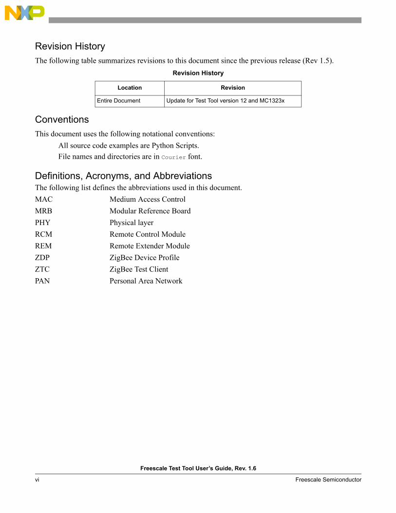
Revision HistoryThe following table summarizes revisions to this document since the previous release (Rev 1.5).
ConventionsThis document uses the following notational conventions:
All source code examples are Python Scripts.File names and directories are in Courier font.
Definitions, Acronyms, and AbbreviationsThe following list defines the abbreviations used in this document.MAC Medium Access ControlMRB Modular Reference BoardPHY Physical layerRCM Remote Control ModuleREM Remote Extender ModuleZDP ZigBee Device ProfileZTC ZigBee Test ClientPAN Personal Area Network
Revision History
Location Revision
Entire Document Update for Test Tool version 12 and MC1323x

Freescale Test Tool User’s Guide, Rev. 1.6
Freescale Semiconductor 1-1
Chapter 1 IntroductionThis chapter introduces the Freescale Test Tool features and basic components. The Freescale Test Tool is a Windows® based graphical interface that communicates with various Freescale ZigBee development boards. The Test Tool provides the following specialized views with different functionality:
• Command Console — Allows users to send and receive ZTC (ZigBee Test Client) based commands commands from a PC to a Freescale ZigBee development board for all 802.15.4 based codebases.
• Script Server — Allows users to load, execute, and review results of Python Scripts and Test Sets in order to automate sets of ZTC commands.
• HCS08 Firmware Loader — Allows users to flash different application code into Freescale ZigBee HCS08 based development boards from Test Tool using a USB multilink device (BDM)
• MC1322x Firmware Loader - Allows users to load application code into the flash memory of MC1322x ARM7 based development boards, using a USB or serial cable connected to the board’s communication port
• Protocol Analyzer — Allows users to visualize 802.15.4 based protocol frames over the air using a Freescale dongle board.
• Coexistence Tool — Allows users to run and log radio interference tests for MAC, BeeStack Consumer, and SynkroRF protocols.
• Radio Test — Allows users to send predefined low-level RF and MCU radio commands to the development board
• OTA BeeStack — Allows users to do Over the Air updates using applications in the BeeStack codebase. See Chapter 10 Using the Over the Air (OTA) Upgrade Cluster in the Freescale ZigBee Application User’s Guide document for an introduction of using the OTA BeeStack view with a BeeStack Application scenario
• OTA Mac — Allows user to do load an S19 image to the flash of a MC1323x board in order to perform an Over the Air update scenario for the HCS08 MAC codebase. See Chapter 3 Software Implementation of the 802.15.4 MAC Over-the-Air Programmer Demonstration Application User’s Guide document for an introduction of using the OTA MAC view with a MAC application scenario.
NOTEThe Command Console and Script Server options require users to have knowledge of the IEEE® 802.15.4 and ZigBee® standards. See the 802.15.4 Standard from the IEEE group for detailed information about the 802.15.4 and ZigBee specifications. Visit www.ieee.org for more information.
Introduction
Freescale Test Tool User’s Guide, Rev. 1.6
1-2 Freescale Semiconductor
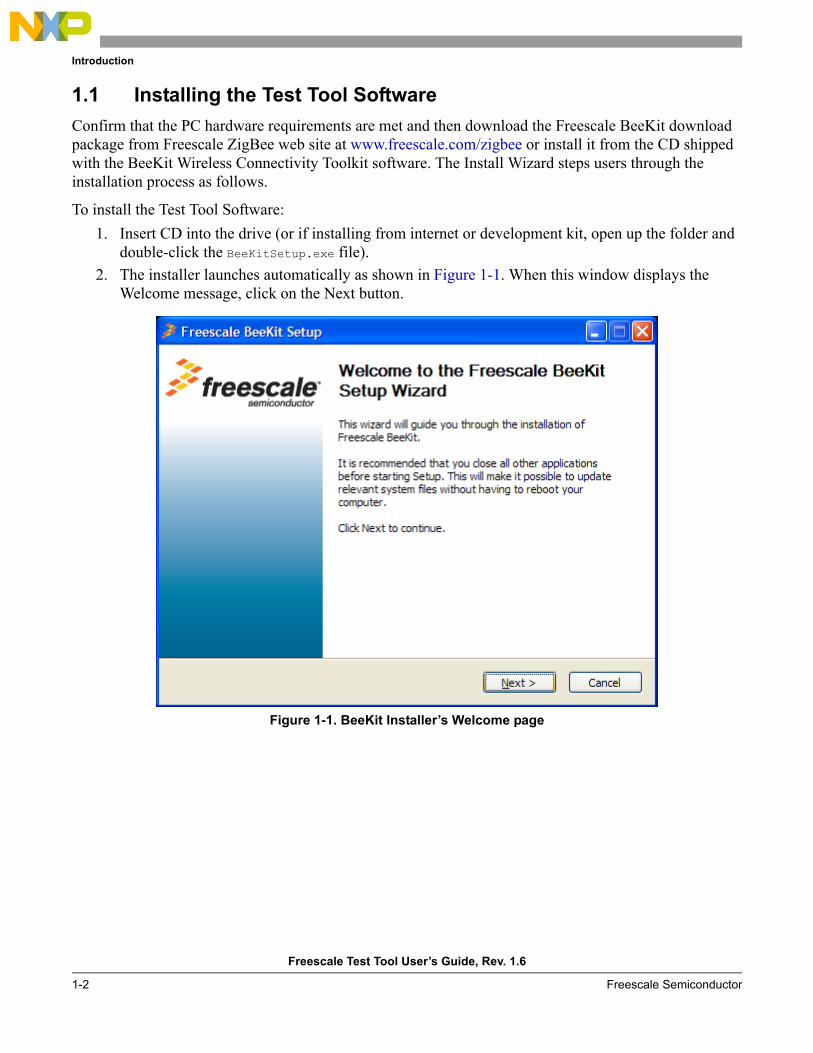
1.1 Installing the Test Tool SoftwareConfirm that the PC hardware requirements are met and then download the Freescale BeeKit download package from Freescale ZigBee web site at www.freescale.com/zigbee or install it from the CD shipped with the BeeKit Wireless Connectivity Toolkit software. The Install Wizard steps users through the installation process as follows.
To install the Test Tool Software:1. Insert CD into the drive (or if installing from internet or development kit, open up the folder and
double-click the BeeKitSetup.exe file).2. The installer launches automatically as shown in Figure 1-1. When this window displays the
Welcome message, click on the Next button.
Figure 1-1. BeeKit Installer’s Welcome page
Introduction
Freescale Test Tool User’s Guide, Rev. 1.6
Freescale Semiconductor 1-3
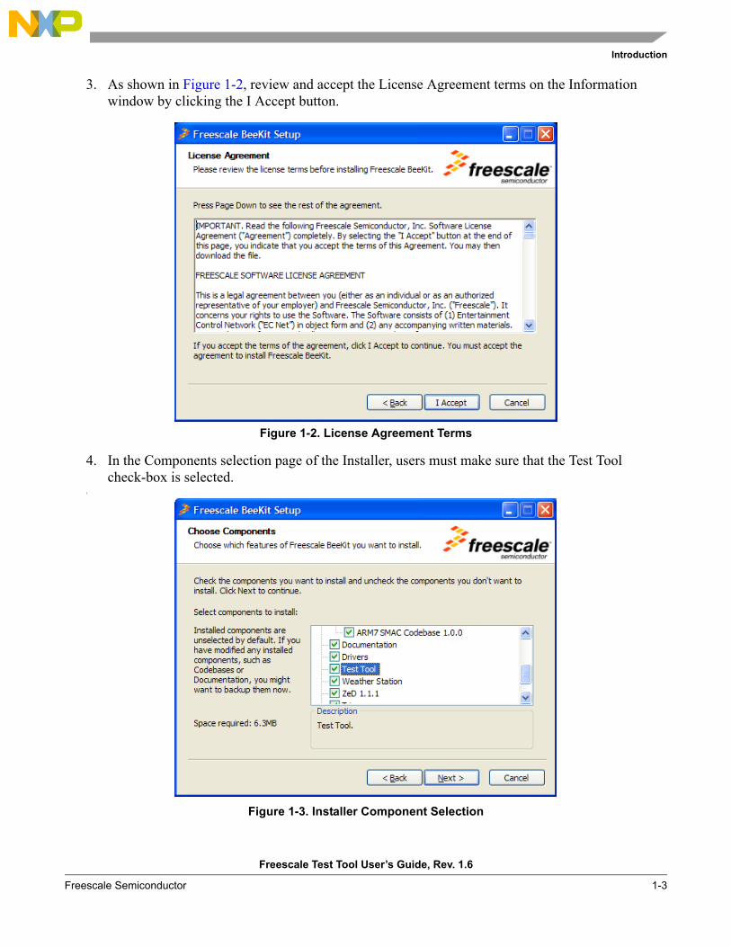
3. As shown in Figure 1-2, review and accept the License Agreement terms on the Information window by clicking the I Accept button.
Figure 1-2. License Agreement Terms
4. In the Components selection page of the Installer, users must make sure that the Test Tool check-box is selected.
5.
Figure 1-3. Installer Component Selection
Introduction
Freescale Test Tool User’s Guide, Rev. 1.6
1-4 Freescale Semiconductor
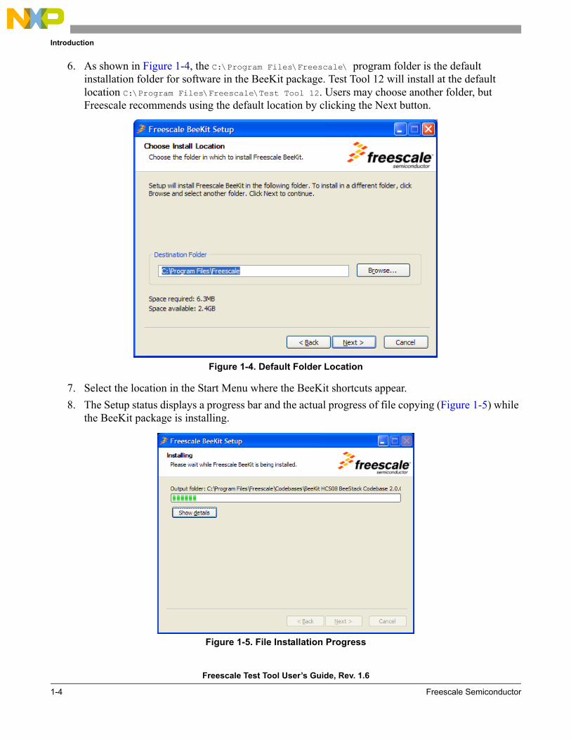
6. As shown in Figure 1-4, the C:\Program Files\Freescale\ program folder is the default installation folder for software in the BeeKit package. Test Tool 12 will install at the default location C:\Program Files\Freescale\Test Tool 12. Users may choose another folder, but Freescale recommends using the default location by clicking the Next button.
Figure 1-4. Default Folder Location
7. Select the location in the Start Menu where the BeeKit shortcuts appear.8. The Setup status displays a progress bar and the actual progress of file copying (Figure 1-5) while
the BeeKit package is installing.
Figure 1-5. File Installation Progress
Introduction
Freescale Test Tool User’s Guide, Rev. 1.6
Freescale Semiconductor 1-5
The Test Tool is ready to use immediately following installation. The included XML files automatically load all of the commands, parameters, and settings required for each test. These XML files allow users to generate API calls in the test environment.
Test Tool can be un-installed from Windows using the BeeKit uninstaller.
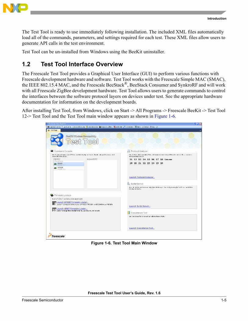
1.2 Test Tool Interface OverviewThe Freescale Test Tool provides a Graphical User Interface (GUI) to perform various functions with Freescale development hardware and software. Test Tool works with the Freescale Simple MAC (SMAC), the IEEE 802.15.4 MAC, and the Freescale BeeStack®, BeeStack Consumer and SynkroRF and will work with all Freescale ZigBee development hardware. Test Tool allows users to generate commands to control the interfaces between the software protocol layers on devices under test. See the appropriate hardware documentation for information on the development boards.
After installing Test Tool, from Windows, click on Start -> All Programs -> Freescale BeeKit -> Test Tool 12-> Test Tool and the Test Tool main window appears as shown in Figure 1-6.
Figure 1-6. Test Tool Main Window
Introduction
Freescale Test Tool User’s Guide, Rev. 1.6
1-6 Freescale Semiconductor
1.2.1 Using the Test Tool Tool BarThis section describes the Test Tool options available from the main window tool bar.
1.2.1.1 Views OptionsThe Views option allows users to launch the Command Console, Script Server, HCS08 Firmware Loader, MC1322x Firmware Loader, Protocol Analyzer, MAC OTA Update, BeeStack OTA Update, Radio Test and Coexistence Tool views.
1.2.1.2 BeeKit OptionThe BeeKit option acts as a shortcut to launch the BeeKit GUI application from Test Tool.
1.2.1.3 Help OptionThe Help option allows users to view the Test Tool documentation.
1.2.1.4 About OptionThe about option allows users to view Test Tool version information.
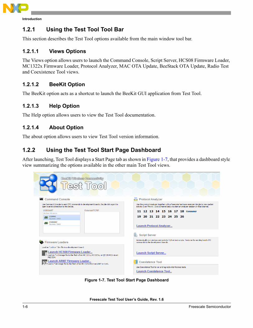
1.2.2 Using the Test Tool Start Page DashboardAfter launching, Test Tool displays a Start Page tab as shown in Figure 1-7, that provides a dashboard style view summarizing the options available in the other main Test Tool views.
Figure 1-7. Test Tool Start Page Dashboard
Introduction
Freescale Test Tool User’s Guide, Rev. 1.6
Freescale Semiconductor 1-7
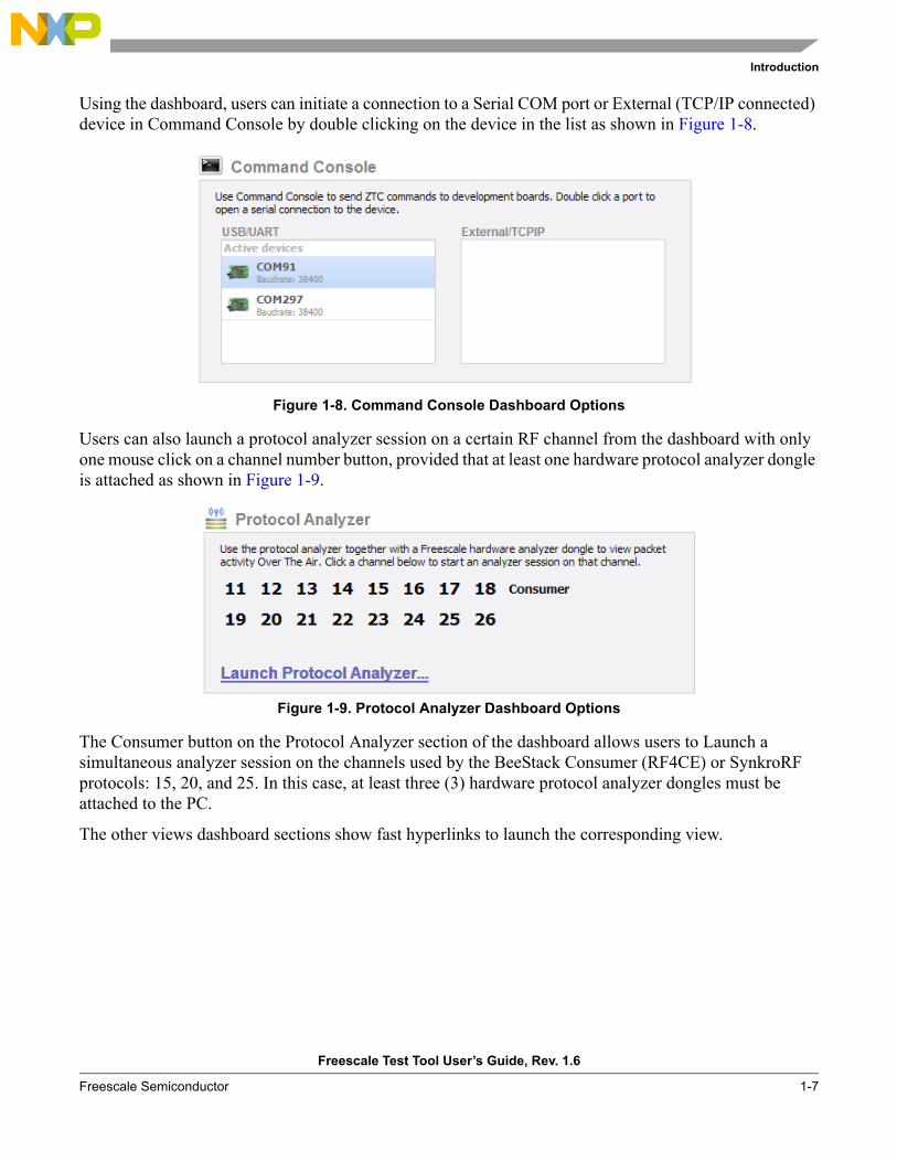
Using the dashboard, users can initiate a connection to a Serial COM port or External (TCP/IP connected) device in Command Console by double clicking on the device in the list as shown in Figure 1-8.
Figure 1-8. Command Console Dashboard Options
Users can also launch a protocol analyzer session on a certain RF channel from the dashboard with only one mouse click on a channel number button, provided that at least one hardware protocol analyzer dongle is attached as shown in Figure 1-9.
Figure 1-9. Protocol Analyzer Dashboard Options
The Consumer button on the Protocol Analyzer section of the dashboard allows users to Launch a simultaneous analyzer session on the channels used by the BeeStack Consumer (RF4CE) or SynkroRF protocols: 15, 20, and 25. In this case, at least three (3) hardware protocol analyzer dongles must be attached to the PC.
The other views dashboard sections show fast hyperlinks to launch the corresponding view.
Introduction
Freescale Test Tool User’s Guide, Rev. 1.6
1-8 Freescale Semiconductor
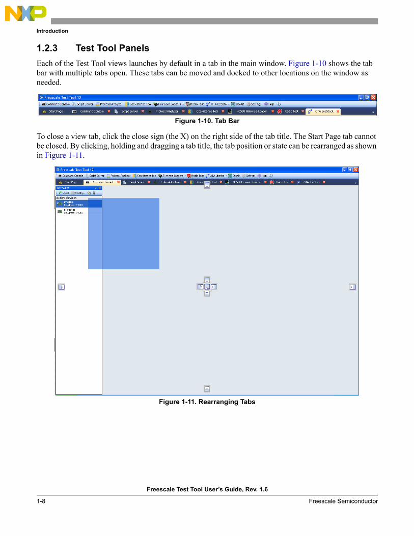
1.2.3 Test Tool PanelsEach of the Test Tool views launches by default in a tab in the main window. Figure 1-10 shows the tab bar with multiple tabs open. These tabs can be moved and docked to other locations on the window as needed.
Figure 1-10. Tab Bar
To close a view tab, click the close sign (the X) on the right side of the tab title. The Start Page tab cannot be closed. By clicking, holding and dragging a tab title, the tab position or state can be rearranged as shown in Figure 1-11.
Figure 1-11. Rearranging Tabs
Introduction
Freescale Test Tool User’s Guide, Rev. 1.6
Freescale Semiconductor 1-9
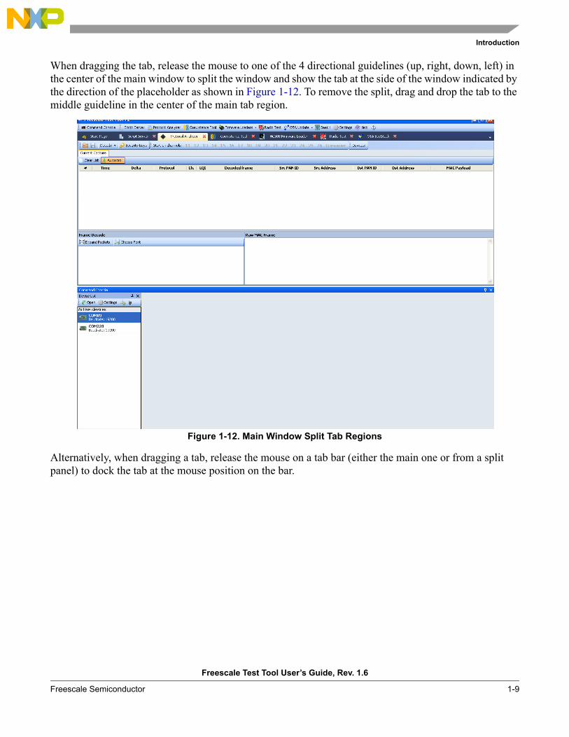
When dragging the tab, release the mouse to one of the 4 directional guidelines (up, right, down, left) in the center of the main window to split the window and show the tab at the side of the window indicated by the direction of the placeholder as shown in Figure 1-12. To remove the split, drag and drop the tab to the middle guideline in the center of the main tab region.
Figure 1-12. Main Window Split Tab Regions
Alternatively, when dragging a tab, release the mouse on a tab bar (either the main one or from a split panel) to dock the tab at the mouse position on the bar.
Introduction
Freescale Test Tool User’s Guide, Rev. 1.6
1-10 Freescale Semiconductor
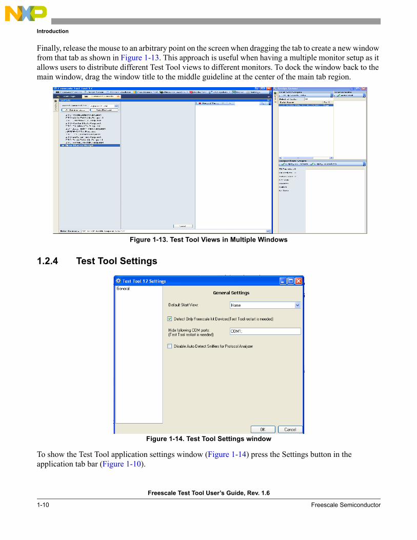
Finally, release the mouse to an arbitrary point on the screen when dragging the tab to create a new window from that tab as shown in Figure 1-13. This approach is useful when having a multiple monitor setup as it allows users to distribute different Test Tool views to different monitors. To dock the window back to the main window, drag the window title to the middle guideline at the center of the main tab region.
Figure 1-13. Test Tool Views in Multiple Windows
1.2.4 Test Tool Settings
Figure 1-14. Test Tool Settings window
To show the Test Tool application settings window (Figure 1-14) press the Settings button in the application tab bar (Figure 1-10).

Introduction
Freescale Test Tool User’s Guide, Rev. 1.6
Freescale Semiconductor 1-11
The Test Tool settings window allows users to set the default start view by selecting one of the views from the Default Start View check box.
If users need to use serial COM ports that use a USB driver to serial converter driver that is different from those used by Freescale development kit boards (FTDI, Silicon Labs), users must deselect “Detect Only Freescale kit Devices“ check box and restart Test Tool.
To prevent a COM port from being auto-detected, add the name of the port in the “Hide following COM ports“ text box followed by semicolon and restart Test Tool.
To disable auto detection of sniffer hardware in the Protocol Analyzer, check the “Disable Auto Detect Sniffer for Protocol Analyzer“ check box. This will allow users to choose a COM port from the device list view to be used as the analyzer hardware.

Introduction
Freescale Test Tool User’s Guide, Rev. 1.6
1-12 Freescale Semiconductor
Freescale Test Tool User’s Guide, Rev. 1.6
Freescale Semiconductor 2-1
Chapter 2 Command ConsoleThe Command Console allows sending and receiving IEEE 802.15.4, SynkroRF, BeeStack Consumer and BeeStack commands from a PC to a Freescale ZigBee development board. The interface requires a working knowledge of the IEEE 802.15.4 Standard and the SynkroRF and the RF4CE and ZigBee Specifications.
2.1 Command Console Hardware and Software ConsiderationsBefore the Command Console becomes functional, set up at least one Freescale evaluation board by connecting it to the PC running Test Tool using a USB cable and making the correct port configuration for the board using the Settings option in the device list tool bar.
When using Test Tool with BeeStack applications, one board must serve as the ZigBee Coordinator. Additional boards can serve as either Routers or End Devices.
When boards are attached to the PC for the first time, the system may ask for the respective device drivers to be installed. The driver install procedure is described in the BeeKit Wireless Connectivity Toolkit User’s Guide, or the appropriate Freescale EVK documentation. If the BeeKit software is already installed at the default location, and the Windows New Hardware Found wizard appears, users should manually steer the software to the following driver location:
C:\Program Files\Freescale\Drivers
WARNINGSome USB hubs or port replicators experience problems assigning serial communication (COM) ports. If USB cables to support each device cannot be directly connected to a PC, consult the hub manufacturer's product specifications for help in resolving port conflicts or connectivity issues.
Before running the Command Console, ensure that the boards have either a MAC, SMAC, or a ZigBee application loaded with ZigBee Test Client (ZTC). The applications can be loaded to the boards using the debugger/loader option in CodeWarrior or Embedded Workbench IDEs or by using the platform specific firmware loaders views available in Test Tool.
Boards are configured using the Settings options in the Command Console device list as shown in Section 2.3.1, “Configuring Serial Ports”.
Command Console
Freescale Test Tool User’s Guide, Rev. 1.6
2-2 Freescale Semiconductor
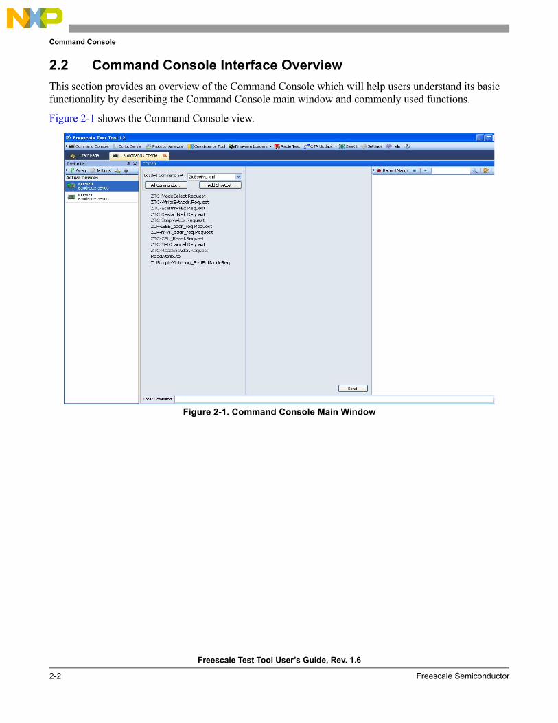
2.2 Command Console Interface OverviewThis section provides an overview of the Command Console which will help users understand its basic functionality by describing the Command Console main window and commonly used functions.
Figure 2-1 shows the Command Console view.
Figure 2-1. Command Console Main Window
Command Console
Freescale Test Tool User’s Guide, Rev. 1.6
Freescale Semiconductor 2-3
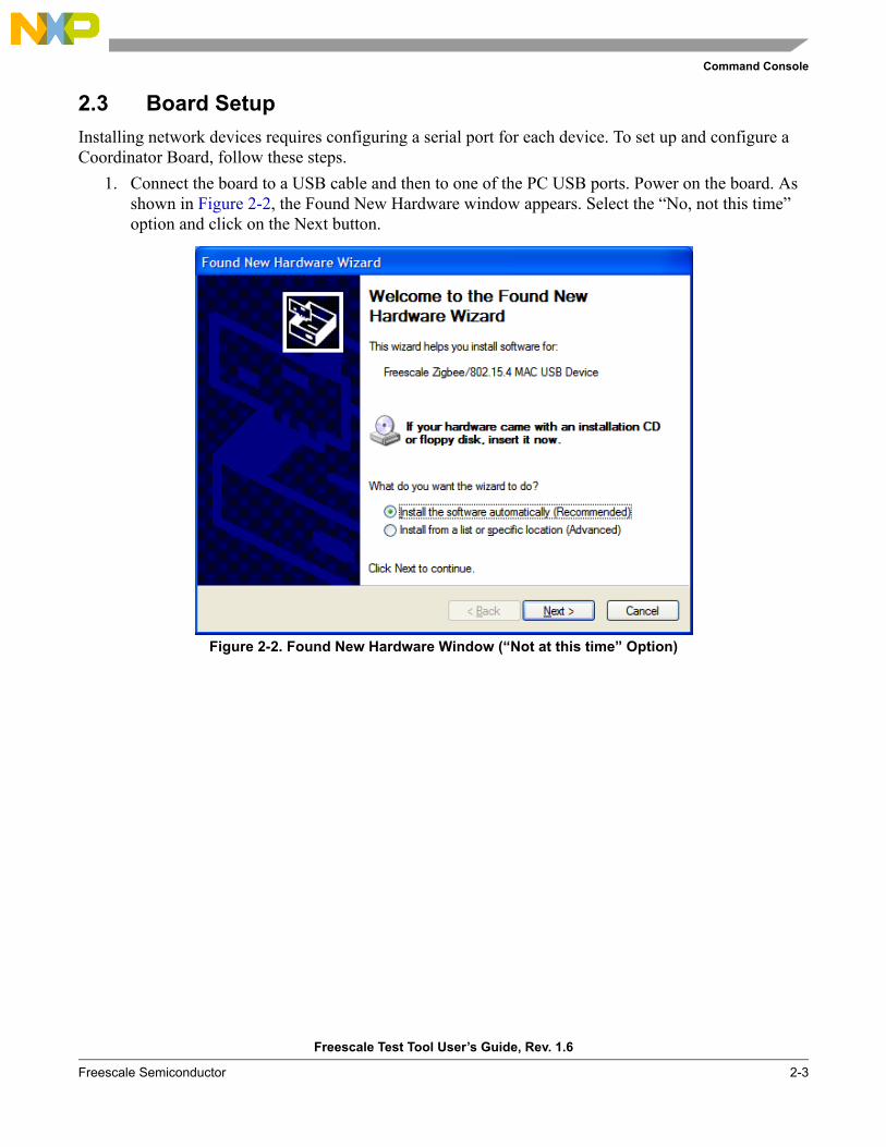
2.3 Board SetupInstalling network devices requires configuring a serial port for each device. To set up and configure a Coordinator Board, follow these steps.
1. Connect the board to a USB cable and then to one of the PC USB ports. Power on the board. As shown in Figure 2-2, the Found New Hardware window appears. Select the “No, not this time” option and click on the Next button.
Figure 2-2. Found New Hardware Window (“Not at this time” Option)
Command Console
Freescale Test Tool User’s Guide, Rev. 1.6
2-4 Freescale Semiconductor
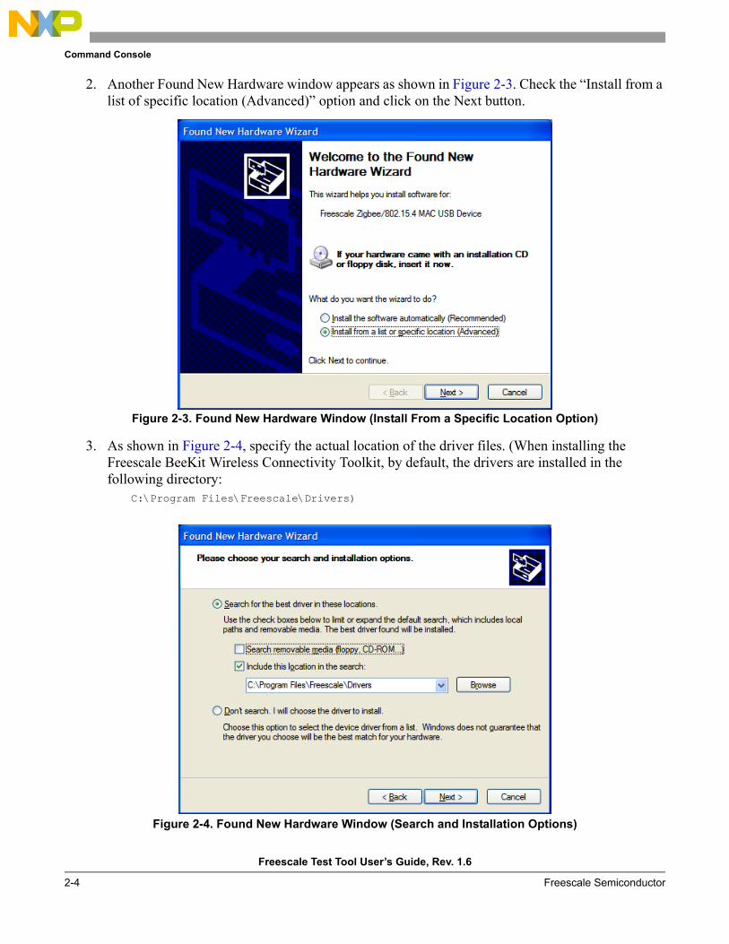
2. Another Found New Hardware window appears as shown in Figure 2-3. Check the “Install from a list of specific location (Advanced)” option and click on the Next button.
Figure 2-3. Found New Hardware Window (Install From a Specific Location Option)
3. As shown in Figure 2-4, specify the actual location of the driver files. (When installing the Freescale BeeKit Wireless Connectivity Toolkit, by default, the drivers are installed in the following directory:
C:\Program Files\Freescale\Drivers)
Figure 2-4. Found New Hardware Window (Search and Installation Options)
Command Console
Freescale Test Tool User’s Guide, Rev. 1.6
Freescale Semiconductor 2-5
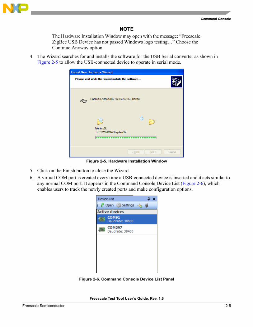
NOTEThe Hardware Installation Window may open with the message: “Freescale ZigBee USB Device has not passed Windows logo testing…” Choose the Continue Anyway option.
4. The Wizard searches for and installs the software for the USB Serial converter as shown in Figure 2-5 to allow the USB-connected device to operate in serial mode.
Figure 2-5. Hardware Installation Window
5. Click on the Finish button to close the Wizard.6. A virtual COM port is created every time a USB-connected device is inserted and it acts similar to
any normal COM port. It appears in the Command Console Device List (Figure 2-6), which enables users to track the newly created ports and make configuration options.
Figure 2-6. Command Console Device List Panel
Command Console
Freescale Test Tool User’s Guide, Rev. 1.6
2-6 Freescale Semiconductor
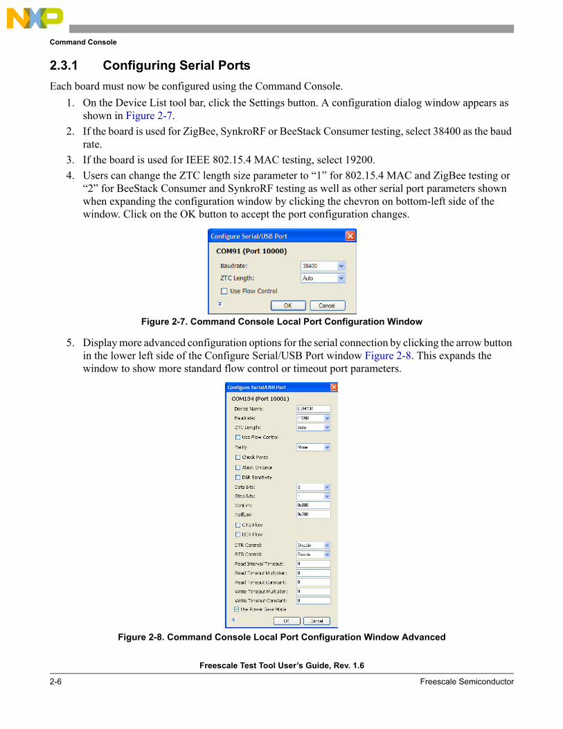
2.3.1 Configuring Serial PortsEach board must now be configured using the Command Console.
1. On the Device List tool bar, click the Settings button. A configuration dialog window appears as shown in Figure 2-7.
2. If the board is used for ZigBee, SynkroRF or BeeStack Consumer testing, select 38400 as the baud rate.
3. If the board is used for IEEE 802.15.4 MAC testing, select 19200. 4. Users can change the ZTC length size parameter to “1” for 802.15.4 MAC and ZigBee testing or
“2” for BeeStack Consumer and SynkroRF testing as well as other serial port parameters shown when expanding the configuration window by clicking the chevron on bottom-left side of the window. Click on the OK button to accept the port configuration changes.
Figure 2-7. Command Console Local Port Configuration Window
5. Display more advanced configuration options for the serial connection by clicking the arrow button in the lower left side of the Configure Serial/USB Port window Figure 2-8. This expands the window to show more standard flow control or timeout port parameters.
Figure 2-8. Command Console Local Port Configuration Window Advanced
Command Console
Freescale Test Tool User’s Guide, Rev. 1.6
Freescale Semiconductor 2-7
Users can also configure Test Tool to send data to devices that are in low power mode and which have the functionality enabled to wake up on serial communication. To enable this feature go to advanced mode. Then, enable check box “Use power Save Mode“ as shown in Figure 2-8. When this feature is activated, each time Test Tool sends a packet to a board, it changes the RTS Control bit to wake up the device if development hardware is configured in this manner.
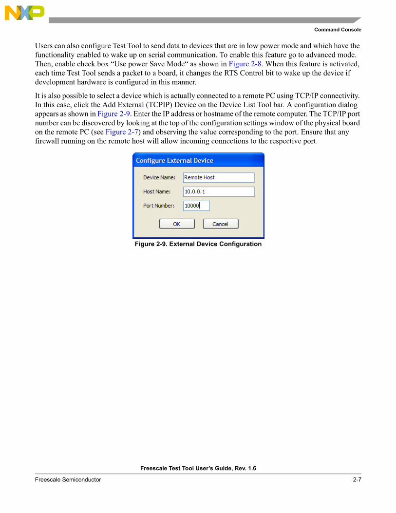
It is also possible to select a device which is actually connected to a remote PC using TCP/IP connectivity. In this case, click the Add External (TCPIP) Device on the Device List Tool bar. A configuration dialog appears as shown in Figure 2-9. Enter the IP address or hostname of the remote computer. The TCP/IP port number can be discovered by looking at the top of the configuration settings window of the physical board on the remote PC (see Figure 2-7) and observing the value corresponding to the port. Ensure that any firewall running on the remote host will allow incoming connections to the respective port.
Figure 2-9. External Device Configuration
Command Console
Freescale Test Tool User’s Guide, Rev. 1.6
2-8 Freescale Semiconductor
2.4 Command Console Operation (802.15.4 MAC Applications)This section describes how to use the Command Console using an IEEE 802.15.4 MAC example.
Ensure that the boards are set up and cables correctly connected as shown in Section 2.3, “Board Setup”. Press the reset button of each board one time before starting the tests outlined in the following sections.
See Section 2.5, “Command Console Operation (ZigBee/BeeStack Applications)” on how to use Command Console using a ZigBee example.
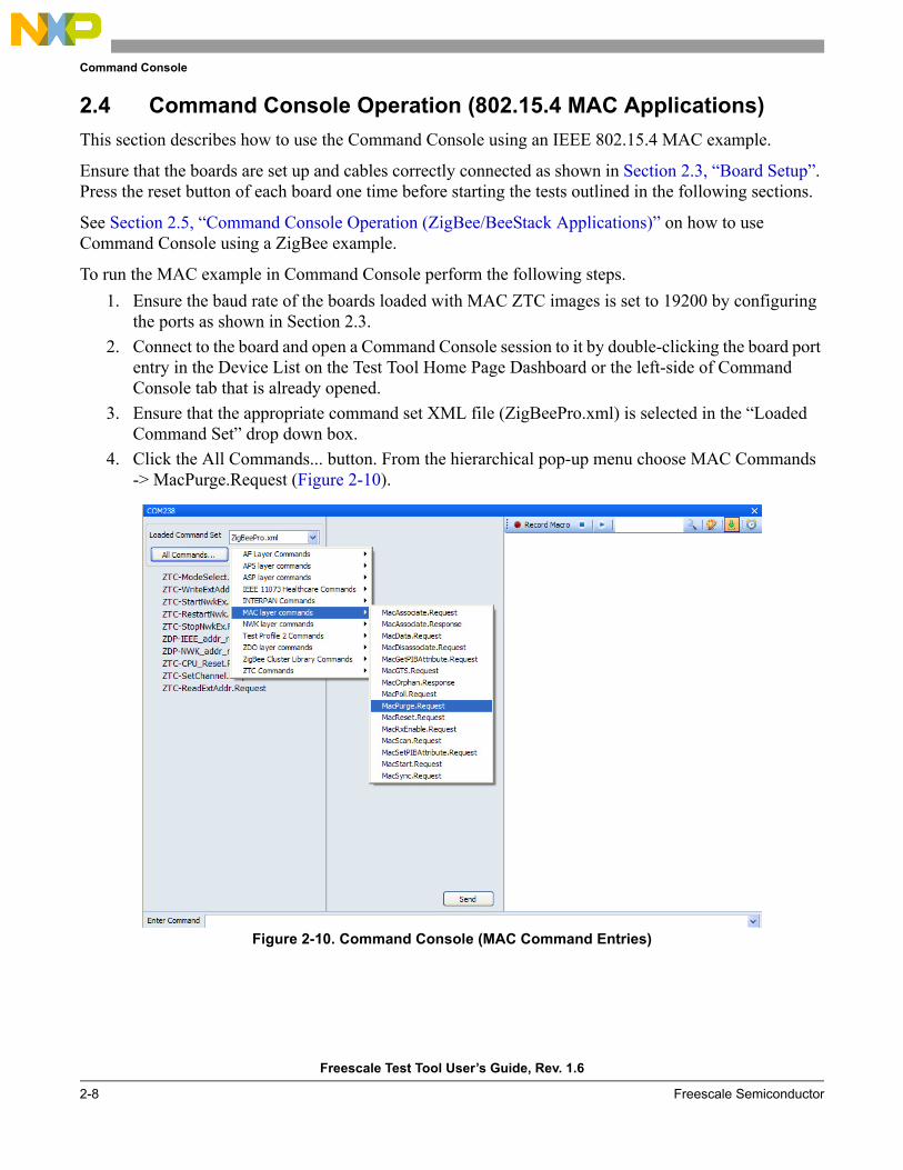
To run the MAC example in Command Console perform the following steps.1. Ensure the baud rate of the boards loaded with MAC ZTC images is set to 19200 by configuring
the ports as shown in Section 2.3.2. Connect to the board and open a Command Console session to it by double-clicking the board port
entry in the Device List on the Test Tool Home Page Dashboard or the left-side of Command Console tab that is already opened.
3. Ensure that the appropriate command set XML file (ZigBeePro.xml) is selected in the “Loaded Command Set” drop down box.
4. Click the All Commands... button. From the hierarchical pop-up menu choose MAC Commands -> MacPurge.Request (Figure 2-10).
Figure 2-10. Command Console (MAC Command Entries)
Command Console
Freescale Test Tool User’s Guide, Rev. 1.6
Freescale Semiconductor 2-9
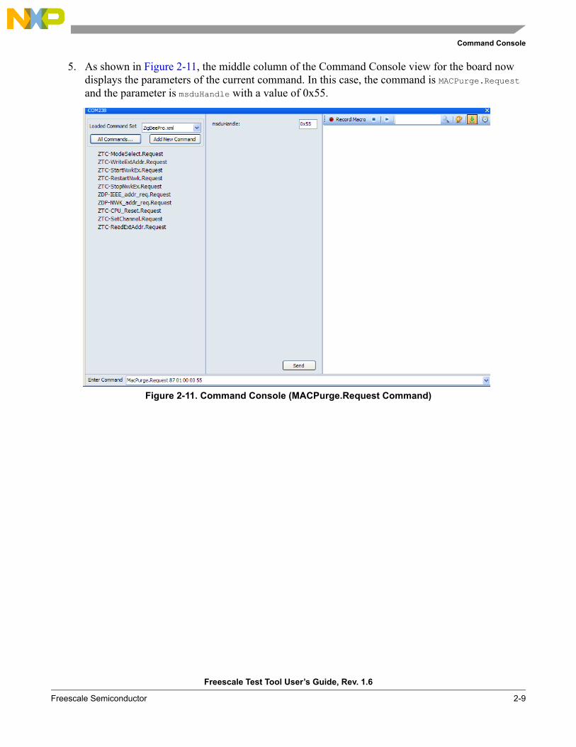
5. As shown in Figure 2-11, the middle column of the Command Console view for the board now displays the parameters of the current command. In this case, the command is MACPurge.Request and the parameter is msduHandle with a value of 0x55.
Figure 2-11. Command Console (MACPurge.Request Command)
Command Console
Freescale Test Tool User’s Guide, Rev. 1.6
2-10 Freescale Semiconductor
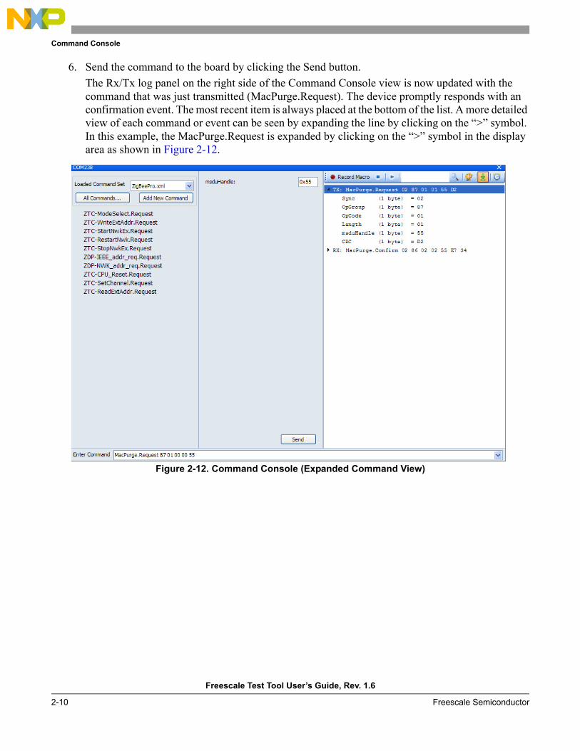
6. Send the command to the board by clicking the Send button. The Rx/Tx log panel on the right side of the Command Console view is now updated with the command that was just transmitted (MacPurge.Request). The device promptly responds with an confirmation event. The most recent item is always placed at the bottom of the list. A more detailed view of each command or event can be seen by expanding the line by clicking on the “>” symbol. In this example, the MacPurge.Request is expanded by clicking on the “>” symbol in the display area as shown in Figure 2-12.
Figure 2-12. Command Console (Expanded Command View)
Command Console
Freescale Test Tool User’s Guide, Rev. 1.6
Freescale Semiconductor 2-11
2.4.1 Starting a MAC Coordinator and Associating a Device To ItBefore working with MAC commands, ensure that the appropriate command set XML (ZigBeePro.XML) is loaded. This example also requires that two boards are programmed with the ZTC application file.
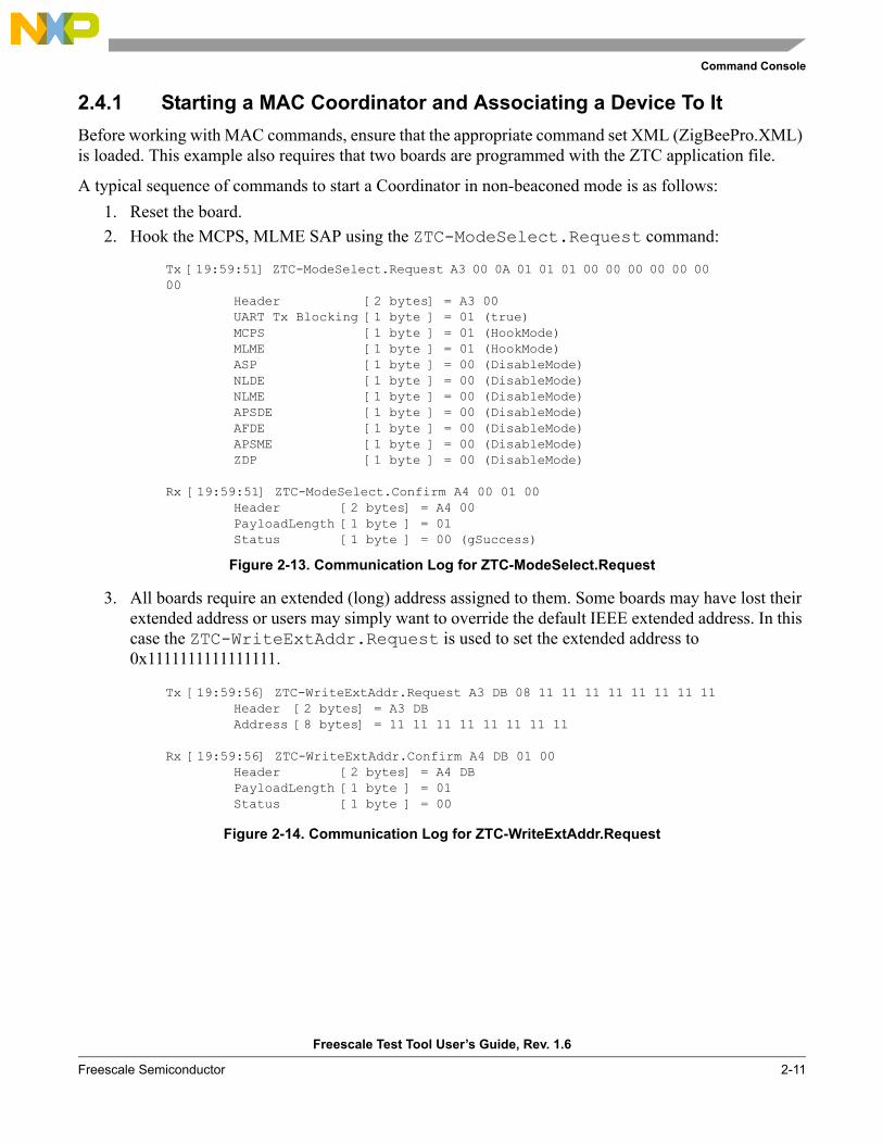
A typical sequence of commands to start a Coordinator in non-beaconed mode is as follows:1. Reset the board.2. Hook the MCPS, MLME SAP using the ZTC-ModeSelect.Request command:
Figure 2-13. Communication Log for ZTC-ModeSelect.Request
3. All boards require an extended (long) address assigned to them. Some boards may have lost their extended address or users may simply want to override the default IEEE extended address. In this case the ZTC-WriteExtAddr.Request is used to set the extended address to 0x1111111111111111.
Figure 2-14. Communication Log for ZTC-WriteExtAddr.Request
Tx [19:59:51] ZTC-ModeSelect.Request A3 00 0A 01 01 01 00 00 00 00 00 00 00
Header [2 bytes] = A3 00UART Tx Blocking [1 byte ] = 01 (true)MCPS [1 byte ] = 01 (HookMode)MLME [1 byte ] = 01 (HookMode)ASP [1 byte ] = 00 (DisableMode)NLDE [1 byte ] = 00 (DisableMode)NLME [1 byte ] = 00 (DisableMode)APSDE [1 byte ] = 00 (DisableMode)AFDE [1 byte ] = 00 (DisableMode)APSME [1 byte ] = 00 (DisableMode)ZDP [1 byte ] = 00 (DisableMode)
Rx [19:59:51] ZTC-ModeSelect.Confirm A4 00 01 00Header [2 bytes] = A4 00PayloadLength [1 byte ] = 01 Status [1 byte ] = 00 (gSuccess)
Tx [19:59:56] ZTC-WriteExtAddr.Request A3 DB 08 11 11 11 11 11 11 11 11Header [2 bytes] = A3 DBAddress [8 bytes] = 11 11 11 11 11 11 11 11
Rx [19:59:56] ZTC-WriteExtAddr.Confirm A4 DB 01 00Header [2 bytes] = A4 DBPayloadLength [1 byte ] = 01 Status [1 byte ] = 00
Command Console
Freescale Test Tool User’s Guide, Rev. 1.6
2-12 Freescale Semiconductor
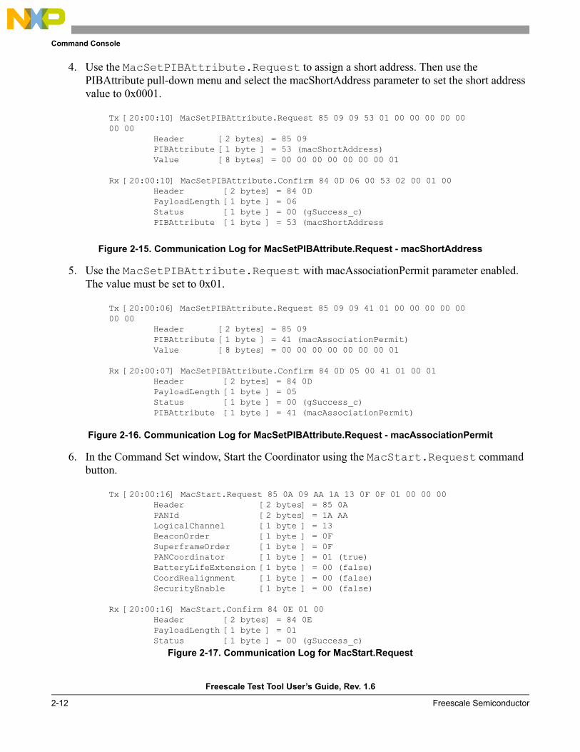
4. Use the MacSetPIBAttribute.Request to assign a short address. Then use the PIBAttribute pull-down menu and select the macShortAddress parameter to set the short address value to 0x0001.
Figure 2-15. Communication Log for MacSetPIBAttribute.Request - macShortAddress
5. Use the MacSetPIBAttribute.Request with macAssociationPermit parameter enabled. The value must be set to 0x01.
Figure 2-16. Communication Log for MacSetPIBAttribute.Request - macAssociationPermit
6. In the Command Set window, Start the Coordinator using the MacStart.Request command button.
Figure 2-17. Communication Log for MacStart.Request
Tx [20:00:10] MacSetPIBAttribute.Request 85 09 09 53 01 00 00 00 00 00 00 00
Header [2 bytes] = 85 09PIBAttribute [1 byte ] = 53 (macShortAddress)Value [8 bytes] = 00 00 00 00 00 00 00 01
Rx [20:00:10] MacSetPIBAttribute.Confirm 84 0D 06 00 53 02 00 01 00Header [2 bytes] = 84 0DPayloadLength [1 byte ] = 06 Status [1 byte ] = 00 (gSuccess_c)PIBAttribute [1 byte ] = 53 (macShortAddress
Tx [20:00:06] MacSetPIBAttribute.Request 85 09 09 41 01 00 00 00 00 00 00 00
Header [2 bytes] = 85 09PIBAttribute [1 byte ] = 41 (macAssociationPermit)Value [8 bytes] = 00 00 00 00 00 00 00 01
Rx [20:00:07] MacSetPIBAttribute.Confirm 84 0D 05 00 41 01 00 01Header [2 bytes] = 84 0DPayloadLength [1 byte ] = 05 Status [1 byte ] = 00 (gSuccess_c)PIBAttribute [1 byte ] = 41 (macAssociationPermit)
Tx [20:00:16] MacStart.Request 85 0A 09 AA 1A 13 0F 0F 01 00 00 00Header [2 bytes] = 85 0APANId [2 bytes] = 1A AA LogicalChannel [1 byte ] = 13 BeaconOrder [1 byte ] = 0F SuperframeOrder [1 byte ] = 0F PANCoordinator [1 byte ] = 01 (true)BatteryLifeExtension [1 byte ] = 00 (false)CoordRealignment [1 byte ] = 00 (false)SecurityEnable [1 byte ] = 00 (false)
Rx [20:00:16] MacStart.Confirm 84 0E 01 00Header [2 bytes] = 84 0EPayloadLength [1 byte ] = 01 Status [1 byte ] = 00 (gSuccess_c)
Command Console
Freescale Test Tool User’s Guide, Rev. 1.6
Freescale Semiconductor 2-13
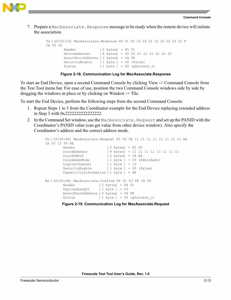
7. Prepare a MacAssociate.Response message to be ready when the remote device will initiate the association.
Figure 2-18. Communication Log for MacAssociate.Response
To start an End Device, open a second Command Console by clicking View -> Command Console from the Test Tool menu bar. For ease of use, position the two Command Console windows side by side by dragging the windows in place or by clicking on Window -> Tile.
To start the End Device, perform the following steps from the second Command Console: 1. Repeat Steps 1 to 3 from the Coordinator example for the End Device replacing extended address
in Step 3 with 0x2222222222222222.2. In the Command Set window, use the MacAssociate.Request and set up the PANID with the
Coordinator’s PANID value (can get value from other device window). Also specify the Coordinator’s address and the correct address mode.
Figure 2-19. Communication Log for MacAssociate.Request
Tx [20:00:23] MacAssociate.Response 85 01 0C 22 22 22 22 22 22 22 22 FECA 00 00
Header [2 bytes] = 85 01DeviceAddress [8 bytes] = 22 22 22 22 22 22 22 22 AssocShortAddress [2 bytes] = CA FE SecurityEnable [1 byte ] = 00 (false)Status [1 byte ] = 00 (gSuccess_c)
Tx [20:00:46] MacAssociate.Request 85 00 0E 11 11 11 11 11 11 11 11 AA1A 03 13 00 8E
Header [2 bytes] = 85 00CoordAddress [8 bytes] = 11 11 11 11 11 11 11 11 CoordPANId [2 bytes] = 1A AA CoordAddrMode [1 byte ] = 03 (64bitAddr)LogicalChannel [1 byte ] = 13 SecurityEnable [1 byte ] = 00 (false)CapabilityInformation [1 byte ] = 8E
Rx [20:00:46] MacAssociate.Confirm 84 01 03 FE CA 00Header [2 bytes] = 84 01PayloadLength [1 byte ] = 03 AssocShortAddress [2 bytes] = CA FE Status [1 byte ] = 00 (gSuccess_c)
Command Console
Freescale Test Tool User’s Guide, Rev. 1.6
2-14 Freescale Semiconductor
2.5 Command Console Operation (ZigBee/BeeStack Applications)This section describes how to initiate tests in Command Console for ZigBee applications. This involves use of the ZigBee Test Client (ZTC) and the TP2 (Test Profile 2) application as provided in the BeeStack Codebases in the Other Projects application template section. For detailed information about the ZTC, see the Freescale BeeStack BlackBox and ZigBee Test Client (ZTC) Reference Manual.
Ensure that the boards are set up and cables correctly connected as shown in Section 2.3, “Board Setup”. Press the reset button of each board one time before starting the tests outlined in the following sections.
At the host PC, start Test Tool, if it is not already running, and follow the steps to access the devices for testing.
From the Test Tool menu bar, follow these steps:1. Ensure the baud rate of the boards loaded with ZigBee ZTC images is set to 38400 by configuring
the ports as shown in Section 2.3.2. Connect to the board loaded with a ZigBee Coordinator ZTC image and open a Command Console
session to it by double-clicking the board port entry in the Device List on the Test Tool Home Page Dashboard or the left-side of a Command Console tab that is already opened.
3. Select the appropriate command set XML (ZigBeePro.xml) from the Command Set panel. This obtains the command and event sets from XML files delivered with codebases and located in the Test Tool XML folder. Additionally, the Quick Access buttons now available correspond to the ZTC Mode, Addressing, and Start/Restart/Stop network request primitives.
4. In the current Command Console view, launch a new device view by double-clicking the entry of the second ZigBee device in the Device List, for this test example, a ZigBee Router.
2.5.1 APS Layer Command TestThe application support sub-layer (APS) enables direct data transmission between two devices using extended or short addresses. The APS creates the interface between the next higher layer entity and the NWK layer and allows binding of devices in the same network. The APS sub-layer services include the following:
• Direct data transmission between two devices using extended or short addresses• Indirect data transmission between two or more devices• Data transmission with end-to-end acknowledgement (APS ACK)• Data transmission using security• Setting up an authenticated relationship between two or more devices using SSP keys
The Application Support Sub-layer Management Entity (APSME) provides management services, and the Application Data Entity (APSDE) transports the APS protocol data units (APDUs) between layers.

Command Console
Freescale Test Tool User’s Guide, Rev. 1.6
Freescale Semiconductor 2-15
2.5.1.1 APS Data RequestThis APSDE-DATA.Request primitive requests the transfer of a next higher layer PDU (ASDU) from the local next higher layer entity (NHLE) to a peer NHLE entity.
This test scenario describes a simple direct APSDE data transfer from the Router to its Coordinator. Both devices must have the TestProfile2 application.
Start by resetting the devices, pressing the RESET button.
From the Command Console window of the ZigBee Coordinator:1. Click on the ZTC-ModeSelect.Request button.2. In the Parameter pane, select the MonitorMode option for APSME, APSDE and ensure the other
SAPs are set to DisableMode.3. Click on the Send button.4. Click on the ZTC-WriteExtAddr.Request button.5. In the parameters pane, type the new address: 0xaaaaaaaaaaaaaaaa.6. Click on the Send button.7. Click on the ZTC-RestartNWK.Request button.8. Click on the Send button.
Repeat the above steps for the ZigBee Router, replacing the address field in step 5 with 0x0000000100000000.
In order to send the APSDE data packet from the Router:1. Click on the All Commands button.2. Click on the APS Layer button.3. Select the APSDE-DATA.Request option.4. In the Parameters pane, select the following:
a) DstAddrMode 0x02 (16-bit address for DestAddress) b) DstAddress to 0x000000000000000 c) DstEndpoint 0xF0 d) Profileld 0x7F01 e) ClusterId 0x001C f) SrcEndpoint 0x01 g) asduLength 0x01 h) Asdu 0x00i) TxOptions 0x00 j) RadiusCounter 0x05
5. Click on the Send button.
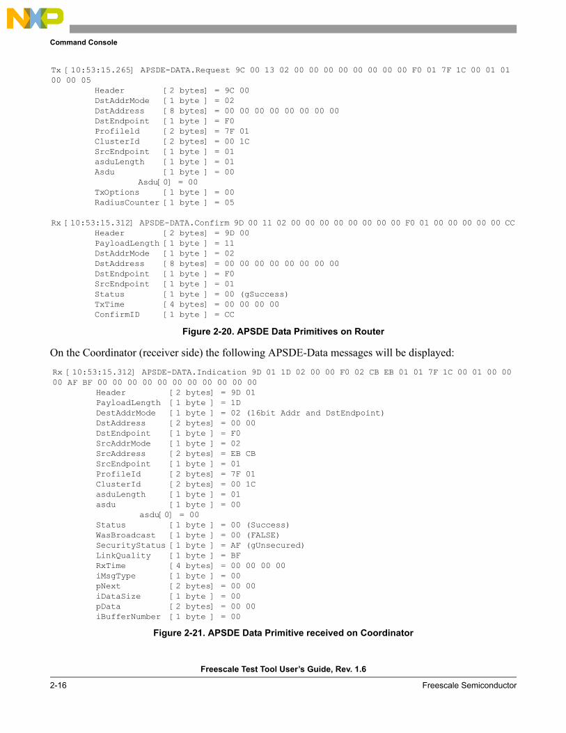
On the Router, the following APSDE-Data messages will be displayed:
Command Console
Freescale Test Tool User’s Guide, Rev. 1.6
2-16 Freescale Semiconductor
Figure 2-20. APSDE Data Primitives on Router
On the Coordinator (receiver side) the following APSDE-Data messages will be displayed:
Figure 2-21. APSDE Data Primitive received on Coordinator
Tx [10:53:15.265] APSDE-DATA.Request 9C 00 13 02 00 00 00 00 00 00 00 00 F0 01 7F 1C 00 01 01 00 00 05
Header [2 bytes] = 9C 00DstAddrMode [1 byte ] = 02 DstAddress [8 bytes] = 00 00 00 00 00 00 00 00 DstEndpoint [1 byte ] = F0 Profileld [2 bytes] = 7F 01 ClusterId [2 bytes] = 00 1C SrcEndpoint [1 byte ] = 01 asduLength [1 byte ] = 01 Asdu [1 byte ] = 00
Asdu[0] = 00TxOptions [1 byte ] = 00 RadiusCounter [1 byte ] = 05
Rx [10:53:15.312] APSDE-DATA.Confirm 9D 00 11 02 00 00 00 00 00 00 00 00 F0 01 00 00 00 00 00 CCHeader [2 bytes] = 9D 00PayloadLength [1 byte ] = 11 DstAddrMode [1 byte ] = 02 DstAddress [8 bytes] = 00 00 00 00 00 00 00 00 DstEndpoint [1 byte ] = F0 SrcEndpoint [1 byte ] = 01 Status [1 byte ] = 00 (gSuccess)TxTime [4 bytes] = 00 00 00 00 ConfirmID [1 byte ] = CC
Rx [10:53:15.312] APSDE-DATA.Indication 9D 01 1D 02 00 00 F0 02 CB EB 01 01 7F 1C 00 01 00 00 00 AF BF 00 00 00 00 00 00 00 00 00 00 00
Header [2 bytes] = 9D 01PayloadLength [1 byte ] = 1D DestAddrMode [1 byte ] = 02 (16bit Addr and DstEndpoint)DstAddress [2 bytes] = 00 00 DstEndpoint [1 byte ] = F0 SrcAddrMode [1 byte ] = 02 SrcAddress [2 bytes] = EB CB SrcEndpoint [1 byte ] = 01 ProfileId [2 bytes] = 7F 01 ClusterId [2 bytes] = 00 1C asduLength [1 byte ] = 01 asdu [1 byte ] = 00
asdu[0] = 00Status [1 byte ] = 00 (Success)WasBroadcast [1 byte ] = 00 (FALSE)SecurityStatus [1 byte ] = AF (gUnsecured)LinkQuality [1 byte ] = BF RxTime [4 bytes] = 00 00 00 00 iMsgType [1 byte ] = 00 pNext [2 bytes] = 00 00 iDataSize [1 byte ] = 00 pData [2 bytes] = 00 00 iBufferNumber [1 byte ] = 00
Command Console
Freescale Test Tool User’s Guide, Rev. 1.6
Freescale Semiconductor 2-17
2.5.2 .ZDO TestZigBee Device Objects (ZDO) manages device and service discovery, and it serves as security manager, network manager, binding manager, and node manager. In general, ZigBee Device Objects function to:
• Initialize the NWK, APS, and SSP layers• Start the network • Provide applications with services to get information about routing, binding, addresses, device
capabilities, and endpoints
2.5.2.1 ZDP IEEE Address RequestThis test verifies that the Device Under Test (DUT) in the role of a ZigBee Coordinator is capable of operating a ZigBee Device Profile (ZDP).
The test ensures that the Router, can send a ZDP-IEEE-Adreess.Request to the Coordinator and receive a response.
1. Start by resetting the devices, pressing the RESET button.2. From the Command Console window of the ZigBee Coordinator:
a) Click on the ZTC-ModeSelect.Request button.b) In the Parameter pane, select the MonitorMode option for APSME, APSDE, ZDP and ensure
the other SAPs are set to DisableMode.c) Click on the Send button.d) Click on the ZTC-WriteExtAddr.Request button.e) In the parameters pane, type the new address: 0xaaaaaaaaaaaaaaaa.f) Click on the Send button.g) Click on the ZTC-RestartNWK.Request button.h) Click on the Send button.
Repeat the above steps for the ZigBee Router, replacing the address field in step 5 with 0x0000000100000000.
From the Command Console of the Router, initiate the ZDP IEEE address request test using these steps:1. Click on the All Commands button.2. Click on the ZDO layer commands button. 3. Select the ZDP-IEEE_addr_req.Request option. 4. In the Parameters pane do the following:
a) Select as the DestAddress 0x0000, coordinator address.b) Select as the NWKAddress 0x0000, coordinator addressc) RequestType 0x01, corresponding to extended response.d) StartIndex 0x00.
5. Click on the Send button.
Command Console
Freescale Test Tool User’s Guide, Rev. 1.6
2-18 Freescale Semiconductor
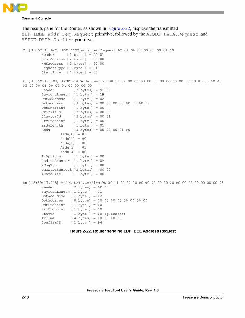
The results pane for the Router, as shown in Figure 2-22, displays the transmitted ZDP-IEEE_addr_req.Request primitive, followed by the APSDE-DATA.Request, and ASPDE-DATA.Confirm primitives.
Figure 2-22. Router sending ZDP IEEE Address Request
Tx [15:59:17.062] ZDP-IEEE_addr_req.Request A2 01 06 00 00 00 00 01 00Header [2 bytes] = A2 01DestAddress [2 bytes] = 00 00 NWKAddress [2 bytes] = 00 00 RequestType [1 byte ] = 01 StartIndex [1 byte ] = 00
Rx [15:59:17.203] APSDE-DATA.Request 9C 00 1B 02 00 00 00 00 00 00 00 00 00 00 00 01 00 00 05 05 00 00 01 00 00 0A 00 00 00 00
Header [2 bytes] = 9C 00PayloadLength [1 byte ] = 1B DstAddrMode [1 byte ] = 02 DstAddress [8 bytes] = 00 00 00 00 00 00 00 00 DstEndpoint [1 byte ] = 00 Profileld [2 bytes] = 00 00 ClusterId [2 bytes] = 00 01 SrcEndpoint [1 byte ] = 00 asduLength [1 byte ] = 05 Asdu [5 bytes] = 05 00 00 01 00
Asdu[0] = 05Asdu[1] = 00Asdu[2] = 00Asdu[3] = 01Asdu[4] = 00
TxOptions [1 byte ] = 00 RadiusCounter [1 byte ] = 0A iMsgType [1 byte ] = 00 pNextDataBlock [2 bytes] = 00 00 iDataSize [1 byte ] = 00
Rx [15:59:17.218] APSDE-DATA.Confirm 9D 00 11 02 00 00 00 00 00 00 00 00 00 00 00 00 00 00 00 96Header [2 bytes] = 9D 00PayloadLength [1 byte ] = 11 DstAddrMode [1 byte ] = 02 DstAddress [8 bytes] = 00 00 00 00 00 00 00 00 DstEndpoint [1 byte ] = 00 SrcEndpoint [1 byte ] = 00 Status [1 byte ] = 00 (gSuccess)TxTime [4 bytes] = 00 00 00 00 ConfirmID [1 byte ] = 96
Command Console
Freescale Test Tool User’s Guide, Rev. 1.6
Freescale Semiconductor 2-19
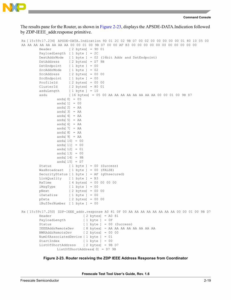
The results pane for the Router, as shown in Figure 2-23, displays the APSDE-DATA.Indication followed by ZDP-IEEE_addr.response primitive.
Figure 2-23. Router receiving the ZDP IEEE Address Response from Coordinator
Rx [15:59:17.234] APSDE-DATA.Indication 9D 01 2C 02 9B D7 00 02 00 00 00 00 00 01 80 10 05 00 AA AA AA AA AA AA AA AA 00 00 01 00 9B D7 00 00 AF B3 00 00 00 00 00 00 00 00 00 00 00
Header [2 bytes] = 9D 01PayloadLength [1 byte ] = 2C DestAddrMode [1 byte ] = 02 (16bit Addr and DstEndpoint)DstAddress [2 bytes] = D7 9B DstEndpoint [1 byte ] = 00 SrcAddrMode [1 byte ] = 02 SrcAddress [2 bytes] = 00 00 SrcEndpoint [1 byte ] = 00 ProfileId [2 bytes] = 00 00 ClusterId [2 bytes] = 80 01 asduLength [1 byte ] = 10 asdu [16 bytes] = 05 00 AA AA AA AA AA AA AA AA 00 00 01 00 9B D7
asdu[0] = 05asdu[1] = 00asdu[2] = AAasdu[3] = AAasdu[4] = AAasdu[5] = AAasdu[6] = AAasdu[7] = AAasdu[8] = AAasdu[9] = AAasdu[10] = 00asdu[11] = 00asdu[12] = 01asdu[13] = 00asdu[14] = 9Basdu[15] = D7
Status [1 byte ] = 00 (Success)WasBroadcast [1 byte ] = 00 (FALSE)SecurityStatus [1 byte ] = AF (gUnsecured)LinkQuality [1 byte ] = B3 RxTime [4 bytes] = 00 00 00 00 iMsgType [1 byte ] = 00 pNext [2 bytes] = 00 00 iDataSize [1 byte ] = 00 pData [2 bytes] = 00 00 iBufferNumber [1 byte ] = 00
Rx [15:59:17.250] ZDP-IEEE_addr.response A0 81 0F 00 AA AA AA AA AA AA AA AA 00 00 01 00 9B D7Header [2 bytes] = A0 81PayloadLength [1 byte ] = 0F Status [1 byte ] = 00 (Success)IEEEAddrRemoteDev [8 bytes] = AA AA AA AA AA AA AA AA NWKAddrRemoteDev [2 bytes] = 00 00 NumOfAssociatedDevice [1 byte ] = 01 StartIndex [1 byte ] = 00 ListOfShortAddress [2 bytes] = 9B D7
ListOfShortAddress[0] = D7 9B

Command Console
Freescale Test Tool User’s Guide, Rev. 1.6
2-20 Freescale Semiconductor
2.5.3 TP2 Free Form Request TestThis test verifies that the DUT in the role of a ZigBee Coordinator is capable of operating a profile on an endpoint (in this example TestProfile2 endpoints are used).
The test ensures that an endpoint on a ZigBee device, in this example the Router, can send a FreeForm.Request to another endpoint (to Coordinator) with an 8-bit integer, and receive a response.
The request type field specifies the FreeForm.Request type based on its value. As shown in Table 2-1, the field can take any one of the non-reserved values listed.
Start by resetting the devices, pressing the RESET button.
From the Command Console window of the ZigBee Coordinator:1. Click on the ZTC-ModeSelect.Request button.2. In the Parameter pane, select the MonitorMode option for APSME, APSDE, AFDE, ZDP and
ensure the other SAPs are set to DisableMode.3. Click on the Send button.4. Click on the ZTC-WriteExtAddr.Request button.5. In the parameters pane, type the new address: 0xaaaaaaaaaaaaaaaa.6. Click on the Send button.7. Click on the ZTC-RestartNWK.Request button.8. Click on the Send button.
Repeat the above steps for the ZigBee Router, replacing the address field in step 5 with 0x0000000100000000.
Table 2-1. Values of Request Type Field
Request Type Field Value Request Description
0x00 Request 8-bit integer value
0x01 Request character string
0x02 Request coordinates
0x03 Request 16-bit integer value
0x04 Request no data value
0x05 Request relative time value
0x06 Request absolute time value
0x07 - 0xff Reserved

Command Console
Freescale Test Tool User’s Guide, Rev. 1.6
Freescale Semiconductor 2-21
From the Command Console of the Router, initiate the Free Form test with these steps:1. Click on the All Commands button.2. Click on the Test Profile 2 button. 3. Select the FreeForm.Request option.4. In the Parameters pane, do the following:
a) Select as the Network Address 0x0000.b) Select as the Request Type 0x00 (the 8-bit integer).
5. Click on the Send button.
The results pane for the Router, as shown in Figure 2-24, displays the transmitted FreeForm.Request primitive, followed by the APSDE-DATA.Request, FreeForm.Confirm, and ASPDE-DATA.Confirm primitives.
Figure 2-24. Primitives Transmitted and Received by the Router
Tx [10:55:32.500] FreeformReq 69 0A 03 00 00 00Header [2 bytes] = 69 0aNetwork_Address [2 bytes] = 00 00 RequestType [1 byte ] = 00
Rx [10:55:32.625] APSDE-DATA.Request 9C 00 17 02 00 00 A1 A1 A1 A1 A1 A1 F0 01 7F A8 A0 01 01 00 00 0A 00 00 00 00
Header [2 bytes] = 9C 00PayloadLength [1 byte ] = 17 DstAddrMode [1 byte ] = 02 DstAddress [8 bytes] = A1 A1 A1 A1 A1 A1 00 00 DstEndpoint [1 byte ] = F0 Profileld [2 bytes] = 7F 01 ClusterId [2 bytes] = A0 A8 SrcEndpoint [1 byte ] = 01 asduLength [1 byte ] = 01 Asdu [1 byte ] = 00
Asdu[0] = 00TxOptions [1 byte ] = 00 RadiusCounter [1 byte ] = 0A iMsgType [1 byte ] = 00 pNextDataBlock [2 bytes] = 00 00 iDataSize [1 byte ] = 00
Rx [10:55:32.640] Freeform.confirm 69 0A 01 00Header [2 bytes] = 69 0aPayloadLength [1 byte ] = 01
Rx [10:55:32.640] APSDE-DATA.Confirm 9D 00 11 02 00 00 A1 A1 A1 A1 A1 A1 F0 01 00 00 00 00 00 CDHeader [2 bytes] = 9D 00PayloadLength [1 byte ] = 11 DstAddrMode [1 byte ] = 02 DstAddress [8 bytes] = A1 A1 A1 A1 A1 A1 00 00 DstEndpoint [1 byte ] = F0 SrcEndpoint [1 byte ] = 01 Status [1 byte ] = 00 (gSuccess)TxTime [4 bytes] = 00 00 00 00 ConfirmID [1 byte ] = CD
Command Console
Freescale Test Tool User’s Guide, Rev. 1.6
2-22 Freescale Semiconductor
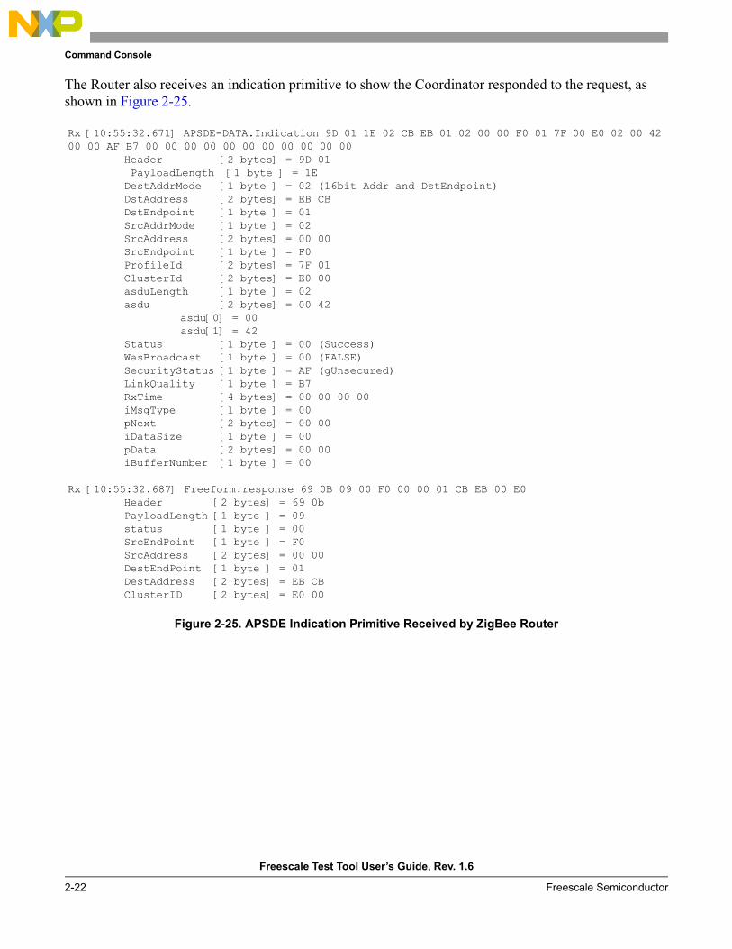
The Router also receives an indication primitive to show the Coordinator responded to the request, as shown in Figure 2-25.
Figure 2-25. APSDE Indication Primitive Received by ZigBee Router
Rx [10:55:32.671] APSDE-DATA.Indication 9D 01 1E 02 CB EB 01 02 00 00 F0 01 7F 00 E0 02 00 42 00 00 AF B7 00 00 00 00 00 00 00 00 00 00 00
Header [2 bytes] = 9D 01 PayloadLength [1 byte ] = 1E DestAddrMode [1 byte ] = 02 (16bit Addr and DstEndpoint)DstAddress [2 bytes] = EB CB DstEndpoint [1 byte ] = 01 SrcAddrMode [1 byte ] = 02 SrcAddress [2 bytes] = 00 00 SrcEndpoint [1 byte ] = F0 ProfileId [2 bytes] = 7F 01 ClusterId [2 bytes] = E0 00 asduLength [1 byte ] = 02 asdu [2 bytes] = 00 42
asdu[0] = 00asdu[1] = 42
Status [1 byte ] = 00 (Success)WasBroadcast [1 byte ] = 00 (FALSE)SecurityStatus [1 byte ] = AF (gUnsecured)LinkQuality [1 byte ] = B7 RxTime [4 bytes] = 00 00 00 00 iMsgType [1 byte ] = 00 pNext [2 bytes] = 00 00 iDataSize [1 byte ] = 00 pData [2 bytes] = 00 00 iBufferNumber [1 byte ] = 00
Rx [10:55:32.687] Freeform.response 69 0B 09 00 F0 00 00 01 CB EB 00 E0Header [2 bytes] = 69 0bPayloadLength [1 byte ] = 09 status [1 byte ] = 00 SrcEndPoint [1 byte ] = F0 SrcAddress [2 bytes] = 00 00 DestEndPoint [1 byte ] = 01 DestAddress [2 bytes] = EB CB ClusterID [2 bytes] = E0 00
Command Console
Freescale Test Tool User’s Guide, Rev. 1.6
Freescale Semiconductor 2-23
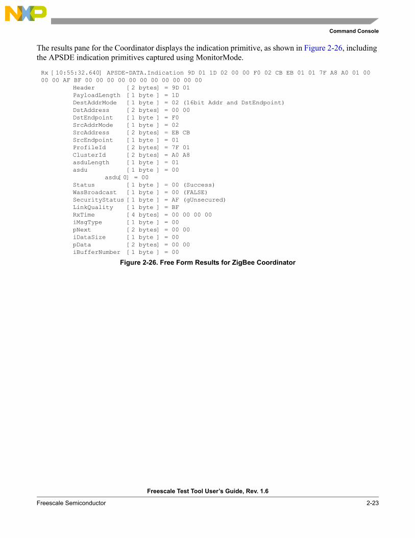
The results pane for the Coordinator displays the indication primitive, as shown in Figure 2-26, including the APSDE indication primitives captured using MonitorMode.
Figure 2-26. Free Form Results for ZigBee Coordinator
Rx [10:55:32.640] APSDE-DATA.Indication 9D 01 1D 02 00 00 F0 02 CB EB 01 01 7F A8 A0 01 00 00 00 AF BF 00 00 00 00 00 00 00 00 00 00 00
Header [2 bytes] = 9D 01PayloadLength [1 byte ] = 1D DestAddrMode [1 byte ] = 02 (16bit Addr and DstEndpoint)DstAddress [2 bytes] = 00 00 DstEndpoint [1 byte ] = F0 SrcAddrMode [1 byte ] = 02 SrcAddress [2 bytes] = EB CB SrcEndpoint [1 byte ] = 01 ProfileId [2 bytes] = 7F 01 ClusterId [2 bytes] = A0 A8 asduLength [1 byte ] = 01 asdu [1 byte ] = 00
asdu[0] = 00Status [1 byte ] = 00 (Success)WasBroadcast [1 byte ] = 00 (FALSE)SecurityStatus [1 byte ] = AF (gUnsecured)LinkQuality [1 byte ] = BF RxTime [4 bytes] = 00 00 00 00 iMsgType [1 byte ] = 00 pNext [2 bytes] = 00 00 iDataSize [1 byte ] = 00 pData [2 bytes] = 00 00 iBufferNumber [1 byte ] = 00
Command Console
Freescale Test Tool User’s Guide, Rev. 1.6
2-24 Freescale Semiconductor
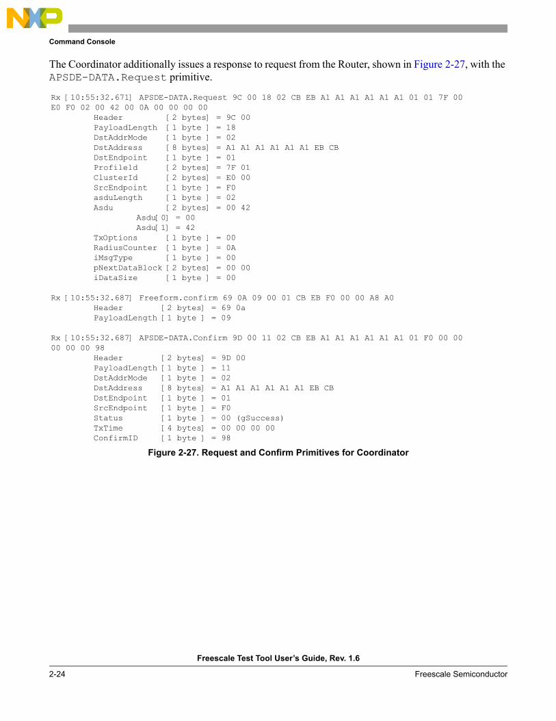
The Coordinator additionally issues a response to request from the Router, shown in Figure 2-27, with the APSDE-DATA.Request primitive.
Figure 2-27. Request and Confirm Primitives for Coordinator
Rx [10:55:32.671] APSDE-DATA.Request 9C 00 18 02 CB EB A1 A1 A1 A1 A1 A1 01 01 7F 00 E0 F0 02 00 42 00 0A 00 00 00 00
Header [2 bytes] = 9C 00PayloadLength [1 byte ] = 18 DstAddrMode [1 byte ] = 02 DstAddress [8 bytes] = A1 A1 A1 A1 A1 A1 EB CB DstEndpoint [1 byte ] = 01 Profileld [2 bytes] = 7F 01 ClusterId [2 bytes] = E0 00 SrcEndpoint [1 byte ] = F0 asduLength [1 byte ] = 02 Asdu [2 bytes] = 00 42
Asdu[0] = 00Asdu[1] = 42
TxOptions [1 byte ] = 00 RadiusCounter [1 byte ] = 0A iMsgType [1 byte ] = 00 pNextDataBlock [2 bytes] = 00 00 iDataSize [1 byte ] = 00
Rx [10:55:32.687] Freeform.confirm 69 0A 09 00 01 CB EB F0 00 00 A8 A0Header [2 bytes] = 69 0aPayloadLength [1 byte ] = 09
Rx [10:55:32.687] APSDE-DATA.Confirm 9D 00 11 02 CB EB A1 A1 A1 A1 A1 A1 01 F0 00 00 00 00 00 98
Header [2 bytes] = 9D 00PayloadLength [1 byte ] = 11 DstAddrMode [1 byte ] = 02 DstAddress [8 bytes] = A1 A1 A1 A1 A1 A1 EB CB DstEndpoint [1 byte ] = 01 SrcEndpoint [1 byte ] = F0 Status [1 byte ] = 00 (gSuccess)TxTime [4 bytes] = 00 00 00 00 ConfirmID [1 byte ] = 98
Command Console
Freescale Test Tool User’s Guide, Rev. 1.6
Freescale Semiconductor 2-25
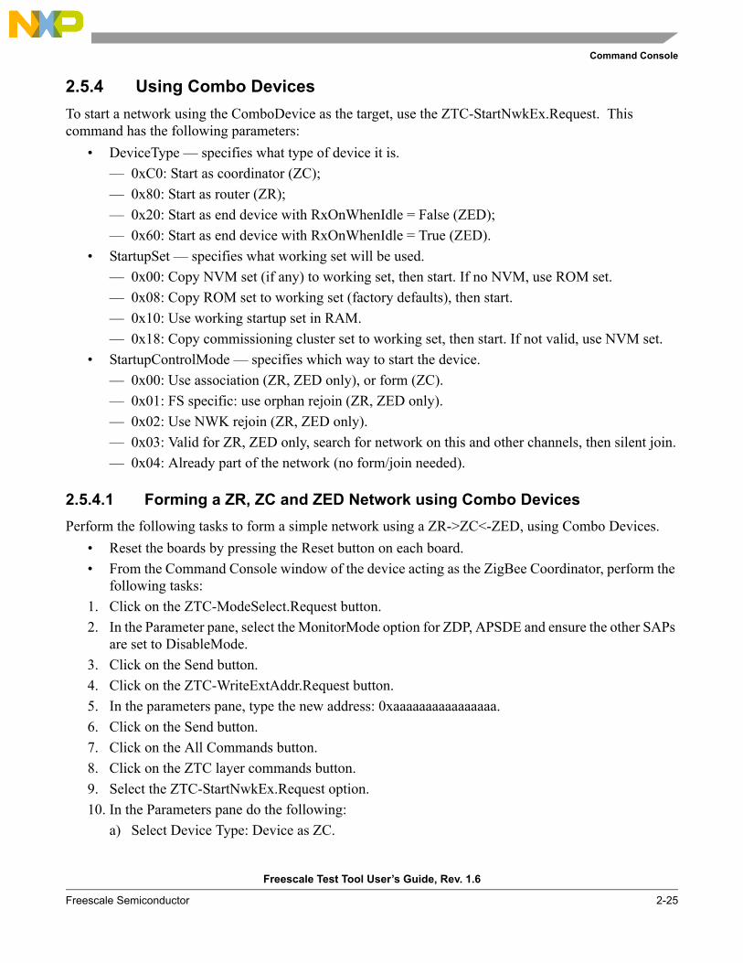
2.5.4 Using Combo DevicesTo start a network using the ComboDevice as the target, use the ZTC-StartNwkEx.Request. This command has the following parameters:
• DeviceType — specifies what type of device it is.— 0xC0: Start as coordinator (ZC);— 0x80: Start as router (ZR);— 0x20: Start as end device with RxOnWhenIdle = False (ZED);— 0x60: Start as end device with RxOnWhenIdle = True (ZED).
• StartupSet — specifies what working set will be used.— 0x00: Copy NVM set (if any) to working set, then start. If no NVM, use ROM set.— 0x08: Copy ROM set to working set (factory defaults), then start.— 0x10: Use working startup set in RAM.— 0x18: Copy commissioning cluster set to working set, then start. If not valid, use NVM set.
• StartupControlMode — specifies which way to start the device.— 0x00: Use association (ZR, ZED only), or form (ZC).— 0x01: FS specific: use orphan rejoin (ZR, ZED only).— 0x02: Use NWK rejoin (ZR, ZED only).— 0x03: Valid for ZR, ZED only, search for network on this and other channels, then silent join.— 0x04: Already part of the network (no form/join needed).
2.5.4.1 Forming a ZR, ZC and ZED Network using Combo DevicesPerform the following tasks to form a simple network using a ZR->ZC<-ZED, using Combo Devices.
• Reset the boards by pressing the Reset button on each board.• From the Command Console window of the device acting as the ZigBee Coordinator, perform the
following tasks:1. Click on the ZTC-ModeSelect.Request button.2. In the Parameter pane, select the MonitorMode option for ZDP, APSDE and ensure the other SAPs
are set to DisableMode.3. Click on the Send button.4. Click on the ZTC-WriteExtAddr.Request button.5. In the parameters pane, type the new address: 0xaaaaaaaaaaaaaaaa.6. Click on the Send button.7. Click on the All Commands button.8. Click on the ZTC layer commands button.9. Select the ZTC-StartNwkEx.Request option. 10. In the Parameters pane do the following:
a) Select Device Type: Device as ZC.
Command Console
Freescale Test Tool User’s Guide, Rev. 1.6
2-26 Freescale Semiconductor
b) Select Startup Set: Use working set.c) Select Startup Control Mode: Association
11. Click on the Send button.
Repeat these steps for the ZigBee Router. Use extended address 0xbbbbbbbbbbbbbb in Step 5, and replace Device Type with Device as ZR in Step 10-a.
Repeat these steps for the ZigBee End Device. Use extended address 0xccccccccccccccc in Step 5 and replacing Device Type with Device as Device as ZED in step 10-a.
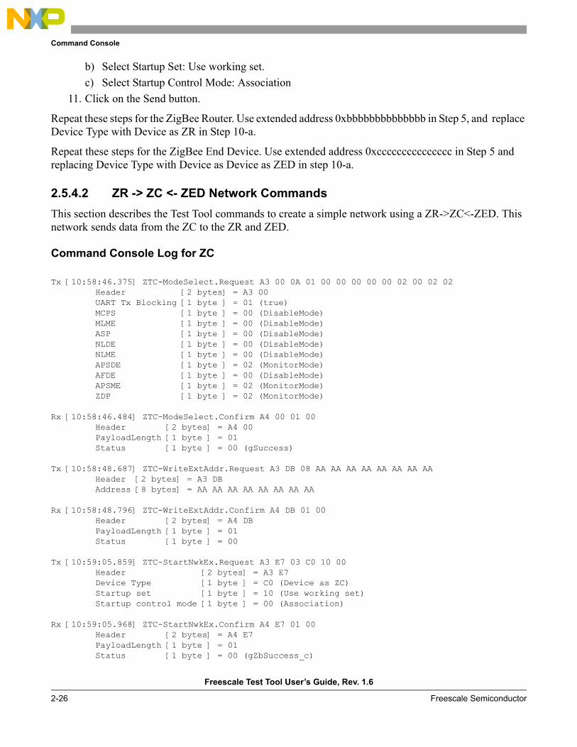
2.5.4.2 ZR -> ZC <- ZED Network CommandsThis section describes the Test Tool commands to create a simple network using a ZR->ZC<-ZED. This network sends data from the ZC to the ZR and ZED.
Command Console Log for ZC
Tx [10:58:46.375] ZTC-ModeSelect.Request A3 00 0A 01 00 00 00 00 00 02 00 02 02Header [2 bytes] = A3 00UART Tx Blocking [1 byte ] = 01 (true)MCPS [1 byte ] = 00 (DisableMode)MLME [1 byte ] = 00 (DisableMode)ASP [1 byte ] = 00 (DisableMode)NLDE [1 byte ] = 00 (DisableMode)NLME [1 byte ] = 00 (DisableMode)APSDE [1 byte ] = 02 (MonitorMode)AFDE [1 byte ] = 00 (DisableMode)APSME [1 byte ] = 02 (MonitorMode)ZDP [1 byte ] = 02 (MonitorMode)
Rx [10:58:46.484] ZTC-ModeSelect.Confirm A4 00 01 00Header [2 bytes] = A4 00PayloadLength [1 byte ] = 01 Status [1 byte ] = 00 (gSuccess)
Tx [10:58:48.687] ZTC-WriteExtAddr.Request A3 DB 08 AA AA AA AA AA AA AA AAHeader [2 bytes] = A3 DBAddress [8 bytes] = AA AA AA AA AA AA AA AA
Rx [10:58:48.796] ZTC-WriteExtAddr.Confirm A4 DB 01 00Header [2 bytes] = A4 DBPayloadLength [1 byte ] = 01 Status [1 byte ] = 00
Tx [10:59:05.859] ZTC-StartNwkEx.Request A3 E7 03 C0 10 00Header [2 bytes] = A3 E7Device Type [1 byte ] = C0 (Device as ZC)Startup set [1 byte ] = 10 (Use working set)Startup control mode [1 byte ] = 00 (Association)
Rx [10:59:05.968] ZTC-StartNwkEx.Confirm A4 E7 01 00Header [2 bytes] = A4 E7PayloadLength [1 byte ] = 01 Status [1 byte ] = 00 (gZbSuccess_c)
Command Console
Freescale Test Tool User’s Guide, Rev. 1.6
Freescale Semiconductor 2-27
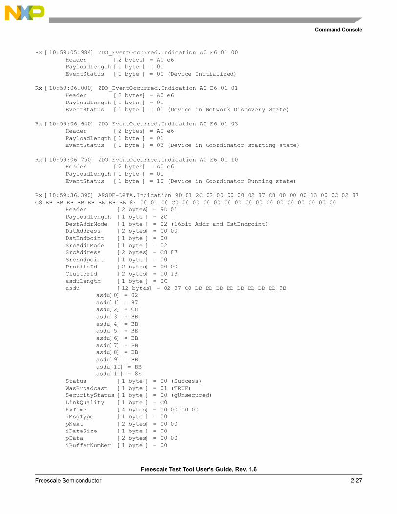
Rx [10:59:05.984] ZDO_EventOccurred.Indication A0 E6 01 00Header [2 bytes] = A0 e6PayloadLength [1 byte ] = 01 EventStatus [1 byte ] = 00 (Device Initialized)
Rx [10:59:06.000] ZDO_EventOccurred.Indication A0 E6 01 01Header [2 bytes] = A0 e6PayloadLength [1 byte ] = 01 EventStatus [1 byte ] = 01 (Device in Network Discovery State)
Rx [10:59:06.640] ZDO_EventOccurred.Indication A0 E6 01 03Header [2 bytes] = A0 e6PayloadLength [1 byte ] = 01 EventStatus [1 byte ] = 03 (Device in Coordinator starting state)
Rx [10:59:06.750] ZDO_EventOccurred.Indication A0 E6 01 10Header [2 bytes] = A0 e6PayloadLength [1 byte ] = 01 EventStatus [1 byte ] = 10 (Device in Coordinator Running state)
Rx [10:59:36.390] APSDE-DATA.Indication 9D 01 2C 02 00 00 00 02 87 C8 00 00 00 13 00 0C 02 87 C8 BB BB BB BB BB BB BB BB 8E 00 01 00 C0 00 00 00 00 00 00 00 00 00 00 00 00 00 00 00
Header [2 bytes] = 9D 01PayloadLength [1 byte ] = 2C DestAddrMode [1 byte ] = 02 (16bit Addr and DstEndpoint)DstAddress [2 bytes] = 00 00 DstEndpoint [1 byte ] = 00 SrcAddrMode [1 byte ] = 02 SrcAddress [2 bytes] = C8 87 SrcEndpoint [1 byte ] = 00 ProfileId [2 bytes] = 00 00 ClusterId [2 bytes] = 00 13 asduLength [1 byte ] = 0C asdu [12 bytes] = 02 87 C8 BB BB BB BB BB BB BB BB 8E
asdu[0] = 02asdu[1] = 87asdu[2] = C8asdu[3] = BBasdu[4] = BBasdu[5] = BBasdu[6] = BBasdu[7] = BBasdu[8] = BBasdu[9] = BBasdu[10] = BBasdu[11] = 8E
Status [1 byte ] = 00 (Success)WasBroadcast [1 byte ] = 01 (TRUE)SecurityStatus [1 byte ] = 00 (gUnsecured)LinkQuality [1 byte ] = C0 RxTime [4 bytes] = 00 00 00 00 iMsgType [1 byte ] = 00 pNext [2 bytes] = 00 00 iDataSize [1 byte ] = 00 pData [2 bytes] = 00 00 iBufferNumber [1 byte ] = 00
Command Console
Freescale Test Tool User’s Guide, Rev. 1.6
2-28 Freescale Semiconductor
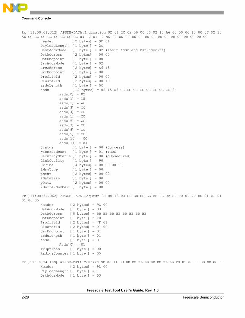
Rx [11:00:01.312] APSDE-DATA.Indication 9D 01 2C 02 00 00 00 02 15 A6 00 00 00 13 00 0C 02 15 A6 CC CC CC CC CC CC CC CC 84 00 01 00 90 00 00 00 00 00 00 00 00 00 00 00 00 00 00 00
Header [2 bytes] = 9D 01PayloadLength [1 byte ] = 2C DestAddrMode [1 byte ] = 02 (16bit Addr and DstEndpoint)DstAddress [2 bytes] = 00 00 DstEndpoint [1 byte ] = 00 SrcAddrMode [1 byte ] = 02 SrcAddress [2 bytes] = A6 15 SrcEndpoint [1 byte ] = 00 ProfileId [2 bytes] = 00 00 ClusterId [2 bytes] = 00 13 asduLength [1 byte ] = 0C asdu [12 bytes] = 02 15 A6 CC CC CC CC CC CC CC CC 84
asdu[0] = 02asdu[1] = 15asdu[2] = A6asdu[3] = CCasdu[4] = CCasdu[5] = CCasdu[6] = CCasdu[7] = CCasdu[8] = CCasdu[9] = CCasdu[10] = CCasdu[11] = 84
Status [1 byte ] = 00 (Success)WasBroadcast [1 byte ] = 01 (TRUE)SecurityStatus [1 byte ] = 00 (gUnsecured)LinkQuality [1 byte ] = 90 RxTime [4 bytes] = 00 00 00 00 iMsgType [1 byte ] = 00 pNext [2 bytes] = 00 00 iDataSize [1 byte ] = 00 pData [2 bytes] = 00 00 iBufferNumber [1 byte ] = 00
Tx [11:00:34.062] APSDE-DATA.Request 9C 00 13 03 BB BB BB BB BB BB BB BB F0 01 7F 00 01 01 01 01 00 05
Header [2 bytes] = 9C 00DstAddrMode [1 byte ] = 03 DstAddress [8 bytes] = BB BB BB BB BB BB BB BB DstEndpoint [1 byte ] = F0 Profileld [2 bytes] = 7F 01 ClusterId [2 bytes] = 01 00 SrcEndpoint [1 byte ] = 01 asduLength [1 byte ] = 01 Asdu [1 byte ] = 01
Asdu[0] = 01TxOptions [1 byte ] = 00 RadiusCounter [1 byte ] = 05
Rx [11:00:34.109] APSDE-DATA.Confirm 9D 00 11 03 BB BB BB BB BB BB BB BB F0 01 00 00 00 00 00 00Header [2 bytes] = 9D 00PayloadLength [1 byte ] = 11 DstAddrMode [1 byte ] = 03
Command Console
Freescale Test Tool User’s Guide, Rev. 1.6
Freescale Semiconductor 2-29
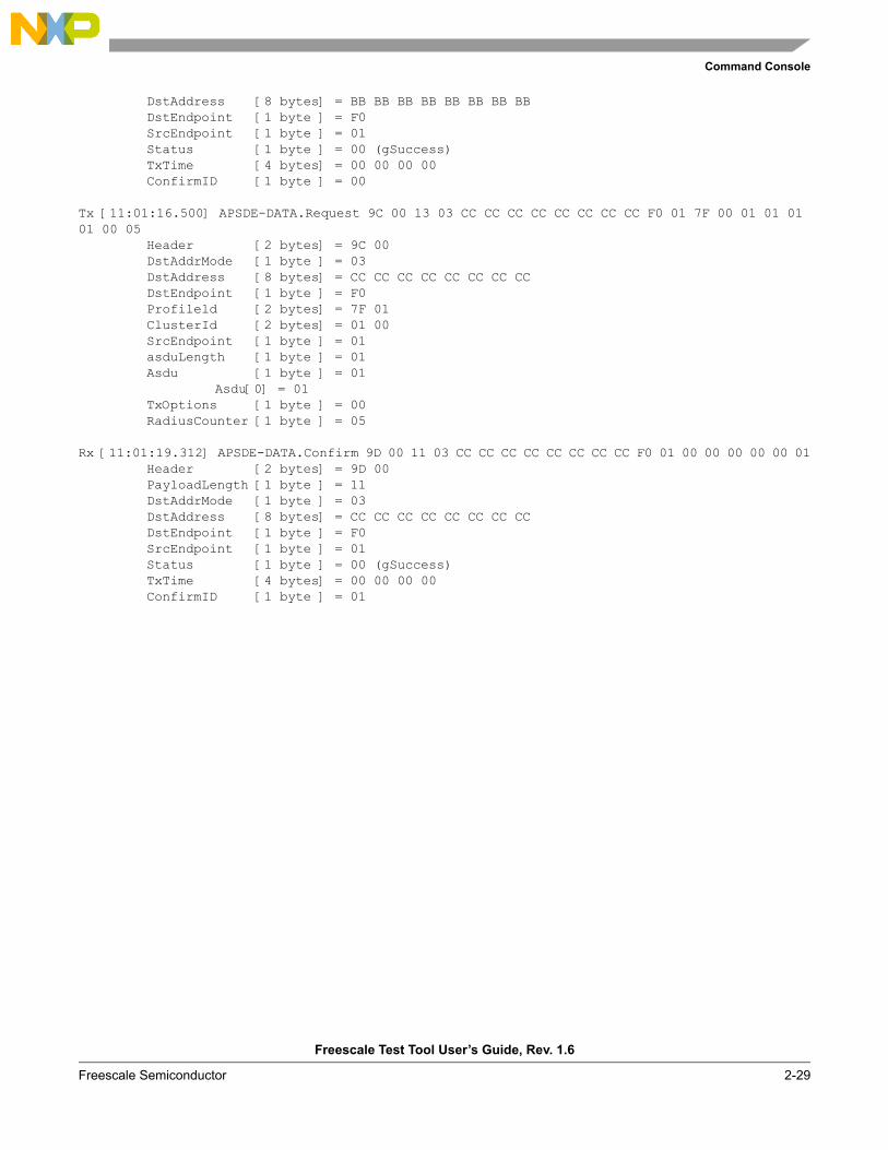
DstAddress [8 bytes] = BB BB BB BB BB BB BB BB DstEndpoint [1 byte ] = F0 SrcEndpoint [1 byte ] = 01 Status [1 byte ] = 00 (gSuccess)TxTime [4 bytes] = 00 00 00 00 ConfirmID [1 byte ] = 00
Tx [11:01:16.500] APSDE-DATA.Request 9C 00 13 03 CC CC CC CC CC CC CC CC F0 01 7F 00 01 01 01 01 00 05
Header [2 bytes] = 9C 00DstAddrMode [1 byte ] = 03 DstAddress [8 bytes] = CC CC CC CC CC CC CC CC DstEndpoint [1 byte ] = F0 Profileld [2 bytes] = 7F 01 ClusterId [2 bytes] = 01 00 SrcEndpoint [1 byte ] = 01 asduLength [1 byte ] = 01 Asdu [1 byte ] = 01
Asdu[0] = 01TxOptions [1 byte ] = 00 RadiusCounter [1 byte ] = 05
Rx [11:01:19.312] APSDE-DATA.Confirm 9D 00 11 03 CC CC CC CC CC CC CC CC F0 01 00 00 00 00 00 01Header [2 bytes] = 9D 00PayloadLength [1 byte ] = 11 DstAddrMode [1 byte ] = 03 DstAddress [8 bytes] = CC CC CC CC CC CC CC CC DstEndpoint [1 byte ] = F0 SrcEndpoint [1 byte ] = 01 Status [1 byte ] = 00 (gSuccess)TxTime [4 bytes] = 00 00 00 00 ConfirmID [1 byte ] = 01
Command Console
Freescale Test Tool User’s Guide, Rev. 1.6
2-30 Freescale Semiconductor
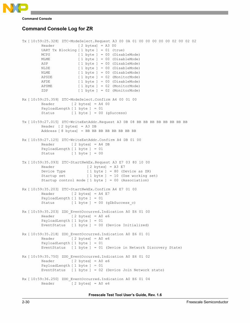
Command Console Log for ZR
Tx [10:59:25.328] ZTC-ModeSelect.Request A3 00 0A 01 00 00 00 00 00 02 00 02 02Header [2 bytes] = A3 00UART Tx Blocking [1 byte ] = 01 (true)MCPS [1 byte ] = 00 (DisableMode)MLME [1 byte ] = 00 (DisableMode)ASP [1 byte ] = 00 (DisableMode)NLDE [1 byte ] = 00 (DisableMode)NLME [1 byte ] = 00 (DisableMode)APSDE [1 byte ] = 02 (MonitorMode)AFDE [1 byte ] = 00 (DisableMode)APSME [1 byte ] = 02 (MonitorMode)ZDP [1 byte ] = 02 (MonitorMode)
Rx [10:59:25.359] ZTC-ModeSelect.Confirm A4 00 01 00Header [2 bytes] = A4 00PayloadLength [1 byte ] = 01 Status [1 byte ] = 00 (gSuccess)
Tx [10:59:27.015] ZTC-WriteExtAddr.Request A3 DB 08 BB BB BB BB BB BB BB BBHeader [2 bytes] = A3 DBAddress [8 bytes] = BB BB BB BB BB BB BB BB
Rx [10:59:27.125] ZTC-WriteExtAddr.Confirm A4 DB 01 00Header [2 bytes] = A4 DBPayloadLength [1 byte ] = 01 Status [1 byte ] = 00
Tx [10:59:35.093] ZTC-StartNwkEx.Request A3 E7 03 80 10 00Header [2 bytes] = A3 E7Device Type [1 byte ] = 80 (Device as ZR)Startup set [1 byte ] = 10 (Use working set)Startup control mode [1 byte ] = 00 (Association)
Rx [10:59:35.203] ZTC-StartNwkEx.Confirm A4 E7 01 00Header [2 bytes] = A4 E7PayloadLength [1 byte ] = 01 Status [1 byte ] = 00 (gZbSuccess_c)
Rx [10:59:35.203] ZDO_EventOccurred.Indication A0 E6 01 00Header [2 bytes] = A0 e6PayloadLength [1 byte ] = 01 EventStatus [1 byte ] = 00 (Device Initialized)
Rx [10:59:35.218] ZDO_EventOccurred.Indication A0 E6 01 01Header [2 bytes] = A0 e6PayloadLength [1 byte ] = 01 EventStatus [1 byte ] = 01 (Device in Network Discovery State)
Rx [10:59:35.750] ZDO_EventOccurred.Indication A0 E6 01 02Header [2 bytes] = A0 e6PayloadLength [1 byte ] = 01 EventStatus [1 byte ] = 02 (Device Join Network state)
Rx [10:59:36.250] ZDO_EventOccurred.Indication A0 E6 01 04Header [2 bytes] = A0 e6
Command Console
Freescale Test Tool User’s Guide, Rev. 1.6
Freescale Semiconductor 2-31
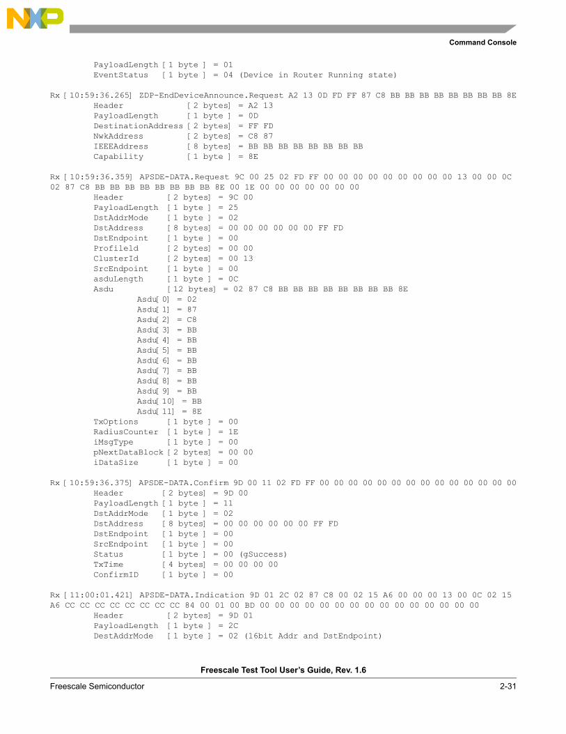
PayloadLength [1 byte ] = 01 EventStatus [1 byte ] = 04 (Device in Router Running state)
Rx [10:59:36.265] ZDP-EndDeviceAnnounce.Request A2 13 0D FD FF 87 C8 BB BB BB BB BB BB BB BB 8EHeader [2 bytes] = A2 13PayloadLength [1 byte ] = 0D DestinationAddress [2 bytes] = FF FD NwkAddress [2 bytes] = C8 87 IEEEAddress [8 bytes] = BB BB BB BB BB BB BB BB Capability [1 byte ] = 8E
Rx [10:59:36.359] APSDE-DATA.Request 9C 00 25 02 FD FF 00 00 00 00 00 00 00 00 00 13 00 00 0C 02 87 C8 BB BB BB BB BB BB BB BB 8E 00 1E 00 00 00 00 00 00 00
Header [2 bytes] = 9C 00PayloadLength [1 byte ] = 25 DstAddrMode [1 byte ] = 02 DstAddress [8 bytes] = 00 00 00 00 00 00 FF FD DstEndpoint [1 byte ] = 00 Profileld [2 bytes] = 00 00 ClusterId [2 bytes] = 00 13 SrcEndpoint [1 byte ] = 00 asduLength [1 byte ] = 0C Asdu [12 bytes] = 02 87 C8 BB BB BB BB BB BB BB BB 8E
Asdu[0] = 02Asdu[1] = 87Asdu[2] = C8Asdu[3] = BBAsdu[4] = BBAsdu[5] = BBAsdu[6] = BBAsdu[7] = BBAsdu[8] = BBAsdu[9] = BBAsdu[10] = BBAsdu[11] = 8E
TxOptions [1 byte ] = 00 RadiusCounter [1 byte ] = 1E iMsgType [1 byte ] = 00 pNextDataBlock [2 bytes] = 00 00 iDataSize [1 byte ] = 00
Rx [10:59:36.375] APSDE-DATA.Confirm 9D 00 11 02 FD FF 00 00 00 00 00 00 00 00 00 00 00 00 00 00Header [2 bytes] = 9D 00PayloadLength [1 byte ] = 11 DstAddrMode [1 byte ] = 02 DstAddress [8 bytes] = 00 00 00 00 00 00 FF FD DstEndpoint [1 byte ] = 00 SrcEndpoint [1 byte ] = 00 Status [1 byte ] = 00 (gSuccess)TxTime [4 bytes] = 00 00 00 00 ConfirmID [1 byte ] = 00
Rx [11:00:01.421] APSDE-DATA.Indication 9D 01 2C 02 87 C8 00 02 15 A6 00 00 00 13 00 0C 02 15 A6 CC CC CC CC CC CC CC CC 84 00 01 00 BD 00 00 00 00 00 00 00 00 00 00 00 00 00 00 00
Header [2 bytes] = 9D 01PayloadLength [1 byte ] = 2C DestAddrMode [1 byte ] = 02 (16bit Addr and DstEndpoint)
Command Console
Freescale Test Tool User’s Guide, Rev. 1.6
2-32 Freescale Semiconductor
DstAddress [2 bytes] = C8 87 DstEndpoint [1 byte ] = 00 SrcAddrMode [1 byte ] = 02 SrcAddress [2 bytes] = A6 15 SrcEndpoint [1 byte ] = 00 ProfileId [2 bytes] = 00 00 ClusterId [2 bytes] = 00 13 asduLength [1 byte ] = 0C asdu [12 bytes] = 02 15 A6 CC CC CC CC CC CC CC CC 84
asdu[0] = 02asdu[1] = 15asdu[2] = A6asdu[3] = CCasdu[4] = CCasdu[5] = CCasdu[6] = CCasdu[7] = CCasdu[8] = CCasdu[9] = CCasdu[10] = CCasdu[11] = 84
Status [1 byte ] = 00 (Success)WasBroadcast [1 byte ] = 01 (TRUE)SecurityStatus [1 byte ] = 00 (gUnsecured)LinkQuality [1 byte ] = BD RxTime [4 bytes] = 00 00 00 00 iMsgType [1 byte ] = 00 pNext [2 bytes] = 00 00 iDataSize [1 byte ] = 00 pData [2 bytes] = 00 00 iBufferNumber [1 byte ] = 00
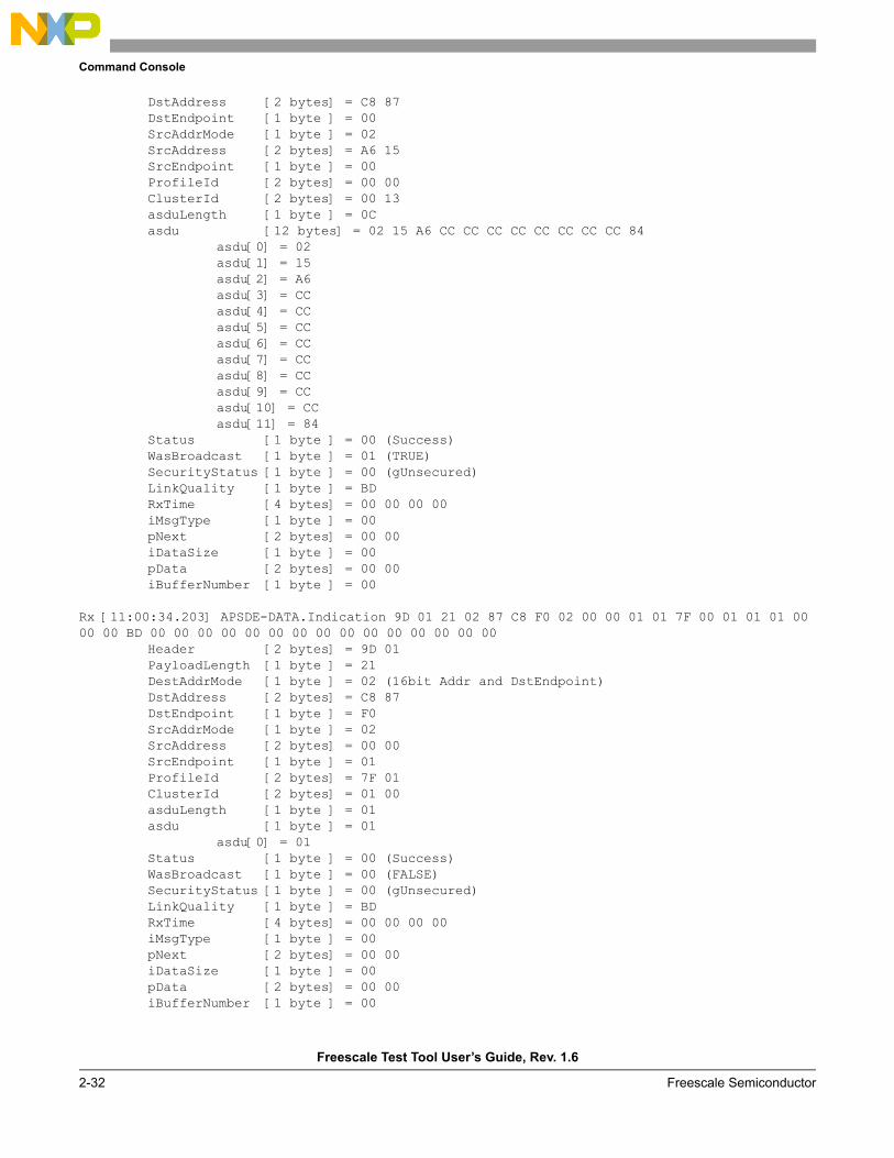
Rx [11:00:34.203] APSDE-DATA.Indication 9D 01 21 02 87 C8 F0 02 00 00 01 01 7F 00 01 01 01 00 00 00 BD 00 00 00 00 00 00 00 00 00 00 00 00 00 00 00
Header [2 bytes] = 9D 01PayloadLength [1 byte ] = 21 DestAddrMode [1 byte ] = 02 (16bit Addr and DstEndpoint)DstAddress [2 bytes] = C8 87 DstEndpoint [1 byte ] = F0 SrcAddrMode [1 byte ] = 02 SrcAddress [2 bytes] = 00 00 SrcEndpoint [1 byte ] = 01 ProfileId [2 bytes] = 7F 01 ClusterId [2 bytes] = 01 00 asduLength [1 byte ] = 01 asdu [1 byte ] = 01
asdu[0] = 01Status [1 byte ] = 00 (Success)WasBroadcast [1 byte ] = 00 (FALSE)SecurityStatus [1 byte ] = 00 (gUnsecured)LinkQuality [1 byte ] = BD RxTime [4 bytes] = 00 00 00 00 iMsgType [1 byte ] = 00 pNext [2 bytes] = 00 00 iDataSize [1 byte ] = 00 pData [2 bytes] = 00 00 iBufferNumber [1 byte ] = 00
Command Console
Freescale Test Tool User’s Guide, Rev. 1.6
Freescale Semiconductor 2-33
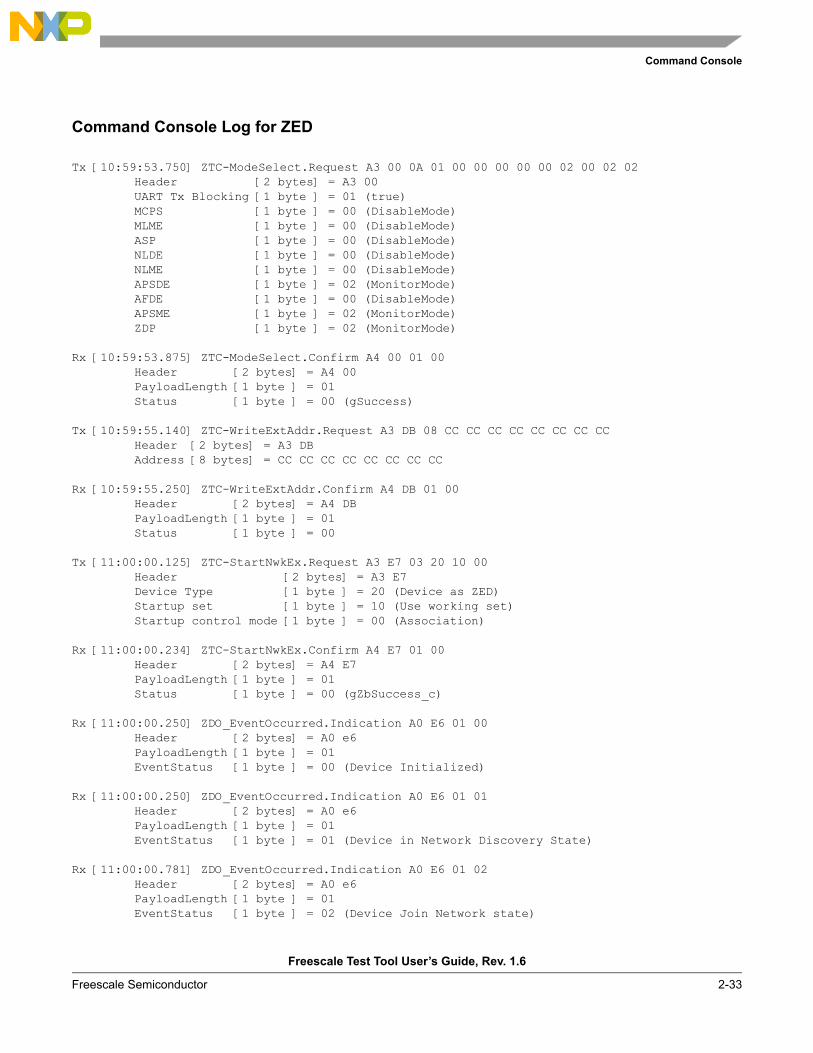
Command Console Log for ZED
Tx [10:59:53.750] ZTC-ModeSelect.Request A3 00 0A 01 00 00 00 00 00 02 00 02 02Header [2 bytes] = A3 00UART Tx Blocking [1 byte ] = 01 (true)MCPS [1 byte ] = 00 (DisableMode)MLME [1 byte ] = 00 (DisableMode)ASP [1 byte ] = 00 (DisableMode)NLDE [1 byte ] = 00 (DisableMode)NLME [1 byte ] = 00 (DisableMode)APSDE [1 byte ] = 02 (MonitorMode)AFDE [1 byte ] = 00 (DisableMode)APSME [1 byte ] = 02 (MonitorMode)ZDP [1 byte ] = 02 (MonitorMode)
Rx [10:59:53.875] ZTC-ModeSelect.Confirm A4 00 01 00Header [2 bytes] = A4 00PayloadLength [1 byte ] = 01 Status [1 byte ] = 00 (gSuccess)
Tx [10:59:55.140] ZTC-WriteExtAddr.Request A3 DB 08 CC CC CC CC CC CC CC CCHeader [2 bytes] = A3 DBAddress [8 bytes] = CC CC CC CC CC CC CC CC
Rx [10:59:55.250] ZTC-WriteExtAddr.Confirm A4 DB 01 00Header [2 bytes] = A4 DBPayloadLength [1 byte ] = 01 Status [1 byte ] = 00
Tx [11:00:00.125] ZTC-StartNwkEx.Request A3 E7 03 20 10 00Header [2 bytes] = A3 E7Device Type [1 byte ] = 20 (Device as ZED)Startup set [1 byte ] = 10 (Use working set)Startup control mode [1 byte ] = 00 (Association)
Rx [11:00:00.234] ZTC-StartNwkEx.Confirm A4 E7 01 00Header [2 bytes] = A4 E7PayloadLength [1 byte ] = 01 Status [1 byte ] = 00 (gZbSuccess_c)
Rx [11:00:00.250] ZDO_EventOccurred.Indication A0 E6 01 00Header [2 bytes] = A0 e6PayloadLength [1 byte ] = 01 EventStatus [1 byte ] = 00 (Device Initialized)
Rx [11:00:00.250] ZDO_EventOccurred.Indication A0 E6 01 01Header [2 bytes] = A0 e6PayloadLength [1 byte ] = 01 EventStatus [1 byte ] = 01 (Device in Network Discovery State)
Rx [11:00:00.781] ZDO_EventOccurred.Indication A0 E6 01 02Header [2 bytes] = A0 e6PayloadLength [1 byte ] = 01 EventStatus [1 byte ] = 02 (Device Join Network state)
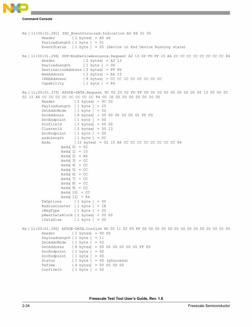
Command Console
Freescale Test Tool User’s Guide, Rev. 1.6
2-34 Freescale Semiconductor
Rx [11:00:01.281] ZDO_EventOccurred.Indication A0 E6 01 05Header [2 bytes] = A0 e6PayloadLength [1 byte ] = 01 EventStatus [1 byte ] = 05 (Device in End Device Running state)
Rx [11:00:01.296] ZDP-EndDeviceAnnounce.Request A2 13 0D FD FF 15 A6 CC CC CC CC CC CC CC CC 84Header [2 bytes] = A2 13PayloadLength [1 byte ] = 0D DestinationAddress [2 bytes] = FF FD NwkAddress [2 bytes] = A6 15 IEEEAddress [8 bytes] = CC CC CC CC CC CC CC CC Capability [1 byte ] = 84
Rx [11:00:01.375] APSDE-DATA.Request 9C 00 25 02 FD FF 00 00 00 00 00 00 00 00 00 13 00 00 0C 02 15 A6 CC CC CC CC CC CC CC CC 84 00 1E 00 00 00 00 00 00 00
Header [2 bytes] = 9C 00PayloadLength [1 byte ] = 25 DstAddrMode [1 byte ] = 02 DstAddress [8 bytes] = 00 00 00 00 00 00 FF FD DstEndpoint [1 byte ] = 00 Profileld [2 bytes] = 00 00 ClusterId [2 bytes] = 00 13 SrcEndpoint [1 byte ] = 00 asduLength [1 byte ] = 0C Asdu [12 bytes] = 02 15 A6 CC CC CC CC CC CC CC CC 84
Asdu[0] = 02Asdu[1] = 15Asdu[2] = A6Asdu[3] = CCAsdu[4] = CCAsdu[5] = CCAsdu[6] = CCAsdu[7] = CCAsdu[8] = CCAsdu[9] = CCAsdu[10] = CCAsdu[11] = 84
TxOptions [1 byte ] = 00 RadiusCounter [1 byte ] = 1E iMsgType [1 byte ] = 00 pNextDataBlock [2 bytes] = 00 00 iDataSize [1 byte ] = 00
Rx [11:00:01.390] APSDE-DATA.Confirm 9D 00 11 02 FD FF 00 00 00 00 00 00 00 00 00 00 00 00 00 00Header [2 bytes] = 9D 00PayloadLength [1 byte ] = 11 DstAddrMode [1 byte ] = 02 DstAddress [8 bytes] = 00 00 00 00 00 00 FF FD DstEndpoint [1 byte ] = 00 SrcEndpoint [1 byte ] = 00 Status [1 byte ] = 00 (gSuccess)TxTime [4 bytes] = 00 00 00 00 ConfirmID [1 byte ] = 00
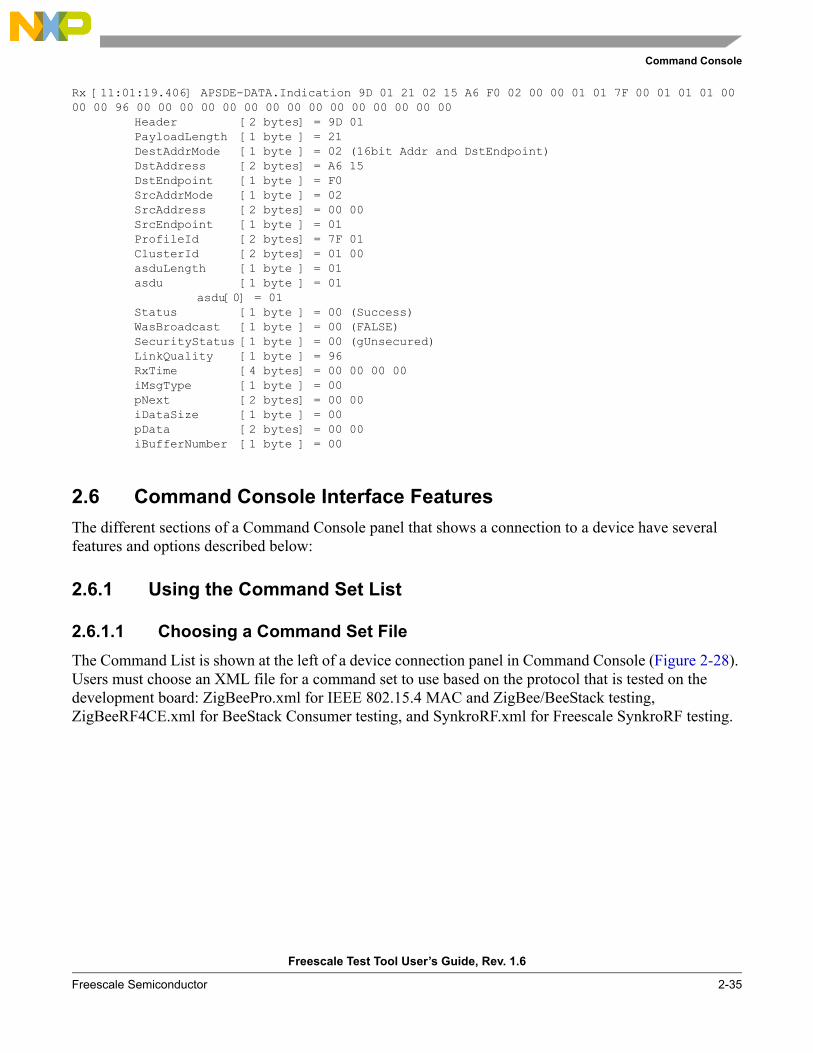
Command Console
Freescale Test Tool User’s Guide, Rev. 1.6
Freescale Semiconductor 2-35
Rx [11:01:19.406] APSDE-DATA.Indication 9D 01 21 02 15 A6 F0 02 00 00 01 01 7F 00 01 01 01 00 00 00 96 00 00 00 00 00 00 00 00 00 00 00 00 00 00 00
Header [2 bytes] = 9D 01PayloadLength [1 byte ] = 21 DestAddrMode [1 byte ] = 02 (16bit Addr and DstEndpoint)DstAddress [2 bytes] = A6 15 DstEndpoint [1 byte ] = F0 SrcAddrMode [1 byte ] = 02 SrcAddress [2 bytes] = 00 00 SrcEndpoint [1 byte ] = 01 ProfileId [2 bytes] = 7F 01 ClusterId [2 bytes] = 01 00 asduLength [1 byte ] = 01 asdu [1 byte ] = 01
asdu[0] = 01Status [1 byte ] = 00 (Success)WasBroadcast [1 byte ] = 00 (FALSE)SecurityStatus [1 byte ] = 00 (gUnsecured)LinkQuality [1 byte ] = 96 RxTime [4 bytes] = 00 00 00 00 iMsgType [1 byte ] = 00 pNext [2 bytes] = 00 00 iDataSize [1 byte ] = 00 pData [2 bytes] = 00 00 iBufferNumber [1 byte ] = 00
2.6 Command Console Interface FeaturesThe different sections of a Command Console panel that shows a connection to a device have several features and options described below:
2.6.1 Using the Command Set List
2.6.1.1 Choosing a Command Set FileThe Command List is shown at the left of a device connection panel in Command Console (Figure 2-28). Users must choose an XML file for a command set to use based on the protocol that is tested on the development board: ZigBeePro.xml for IEEE 802.15.4 MAC and ZigBee/BeeStack testing, ZigBeeRF4CE.xml for BeeStack Consumer testing, and SynkroRF.xml for Freescale SynkroRF testing.
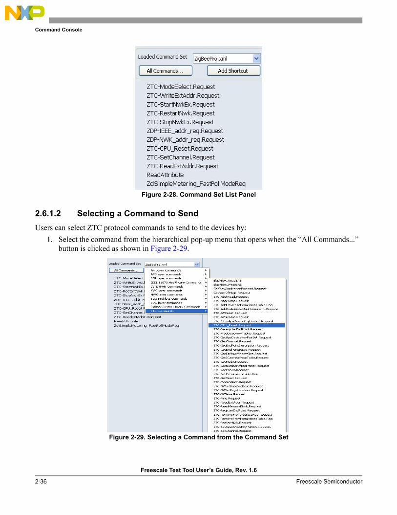
Command Console
Freescale Test Tool User’s Guide, Rev. 1.6
2-36 Freescale Semiconductor
Figure 2-28. Command Set List Panel
2.6.1.2 Selecting a Command to SendUsers can select ZTC protocol commands to send to the devices by:
1. Select the command from the hierarchical pop-up menu that opens when the “All Commands...” button is clicked as shown in Figure 2-29.
Figure 2-29. Selecting a Command from the Command Set
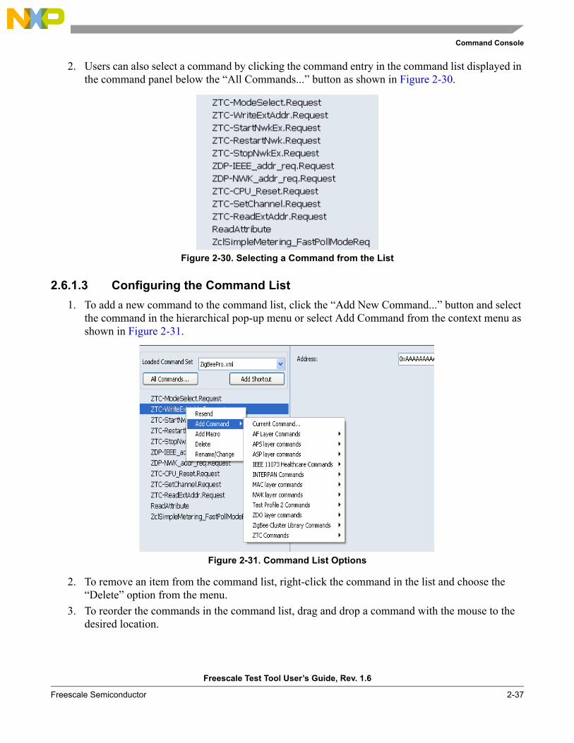
Command Console
Freescale Test Tool User’s Guide, Rev. 1.6
Freescale Semiconductor 2-37
2. Users can also select a command by clicking the command entry in the command list displayed in the command panel below the “All Commands...” button as shown in Figure 2-30.
Figure 2-30. Selecting a Command from the List
2.6.1.3 Configuring the Command List1. To add a new command to the command list, click the “Add New Command...” button and select
the command in the hierarchical pop-up menu or select Add Command from the context menu as shown in Figure 2-31.
Figure 2-31. Command List Options
2. To remove an item from the command list, right-click the command in the list and choose the “Delete” option from the menu.
3. To reorder the commands in the command list, drag and drop a command with the mouse to the desired location.
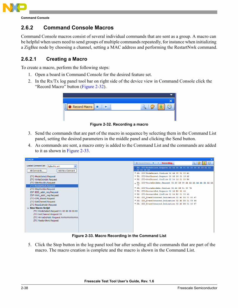
Command Console
Freescale Test Tool User’s Guide, Rev. 1.6
2-38 Freescale Semiconductor
2.6.2 Command Console MacrosCommand Console macros consist of several individual commands that are sent as a group. A macro can be helpful when users need to send groups of multiple commands repeatedly, for instance when initializing a ZigBee node by choosing a channel, setting a MAC address and performing the RestartNwk command.
2.6.2.1 Creating a MacroTo create a macro, perform the following steps:
1. Open a board in Command Console for the desired feature set.2. In the Rx/Tx log panel tool bar on right side of the device view in Command Console click the
“Record Macro” button (Figure 2-32).
Figure 2-32. Recording a macro
3. Send the commands that are part of the macro in sequence by selecting them in the Command List panel, setting the desired parameters in the middle panel and clicking the Send button.
4. As commands are sent, a macro entry is added to the Command List and the commands are added to it as shown in Figure 2-33.
Figure 2-33. Macro Recording in the Command List
5. Click the Stop button in the log panel tool bar after sending all the commands that are part of the macro. The macro creation is complete and the macro is shown in the Command List.
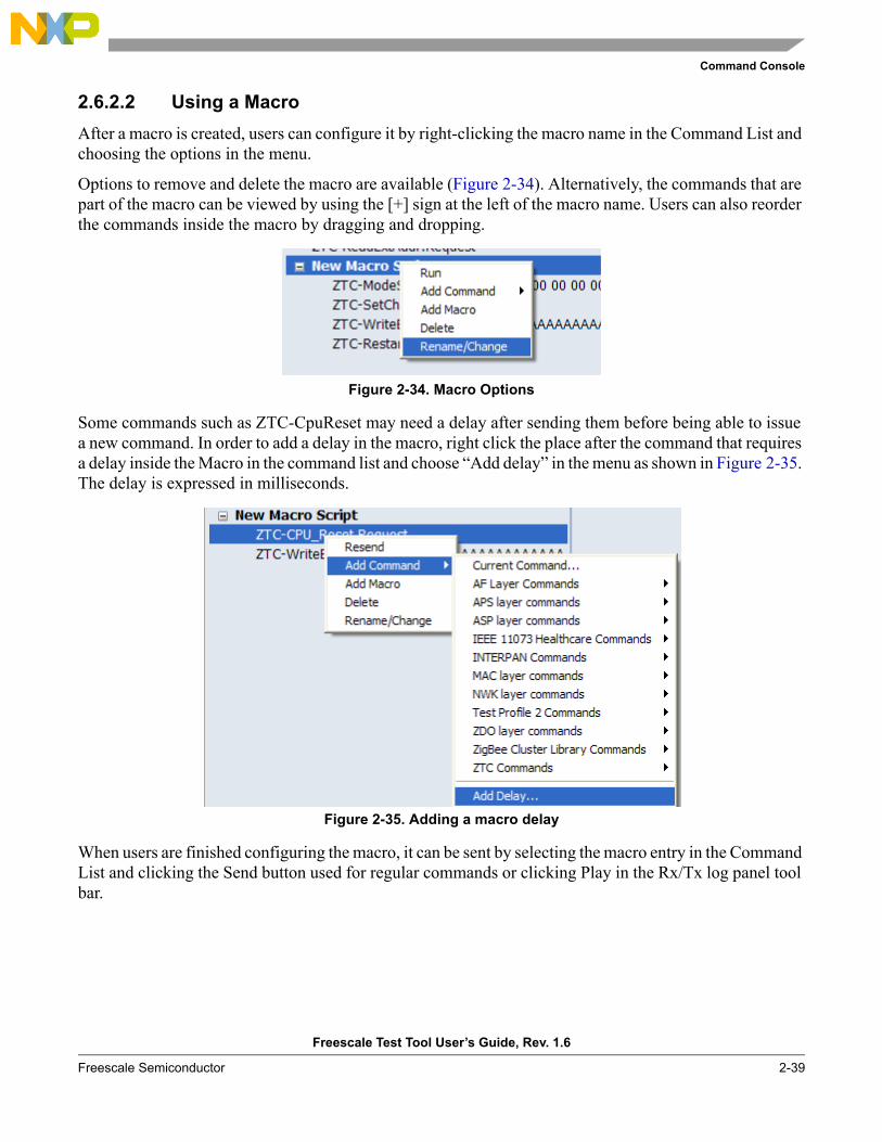
Command Console
Freescale Test Tool User’s Guide, Rev. 1.6
Freescale Semiconductor 2-39
2.6.2.2 Using a MacroAfter a macro is created, users can configure it by right-clicking the macro name in the Command List and choosing the options in the menu.
Options to remove and delete the macro are available (Figure 2-34). Alternatively, the commands that are part of the macro can be viewed by using the [+] sign at the left of the macro name. Users can also reorder the commands inside the macro by dragging and dropping.
Figure 2-34. Macro Options
Some commands such as ZTC-CpuReset may need a delay after sending them before being able to issue a new command. In order to add a delay in the macro, right click the place after the command that requires a delay inside the Macro in the command list and choose “Add delay” in the menu as shown in Figure 2-35. The delay is expressed in milliseconds.
Figure 2-35. Adding a macro delay
When users are finished configuring the macro, it can be sent by selecting the macro entry in the Command List and clicking the Send button used for regular commands or clicking Play in the Rx/Tx log panel tool bar.
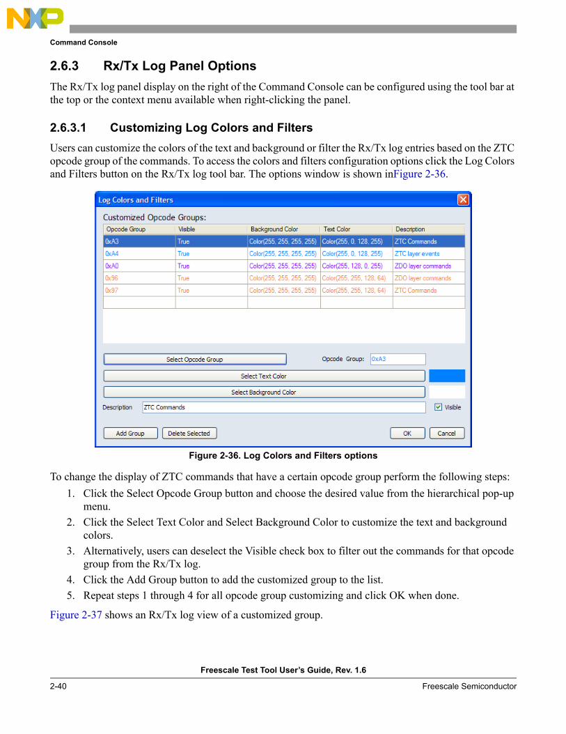
Command Console
Freescale Test Tool User’s Guide, Rev. 1.6
2-40 Freescale Semiconductor
2.6.3 Rx/Tx Log Panel OptionsThe Rx/Tx log panel display on the right of the Command Console can be configured using the tool bar at the top or the context menu available when right-clicking the panel.
2.6.3.1 Customizing Log Colors and FiltersUsers can customize the colors of the text and background or filter the Rx/Tx log entries based on the ZTC opcode group of the commands. To access the colors and filters configuration options click the Log Colors and Filters button on the Rx/Tx log tool bar. The options window is shown inFigure 2-36.
Figure 2-36. Log Colors and Filters options
To change the display of ZTC commands that have a certain opcode group perform the following steps:1. Click the Select Opcode Group button and choose the desired value from the hierarchical pop-up
menu.2. Click the Select Text Color and Select Background Color to customize the text and background
colors.3. Alternatively, users can deselect the Visible check box to filter out the commands for that opcode
group from the Rx/Tx log.4. Click the Add Group button to add the customized group to the list.5. Repeat steps 1 through 4 for all opcode group customizing and click OK when done.
Figure 2-37 shows an Rx/Tx log view of a customized group.
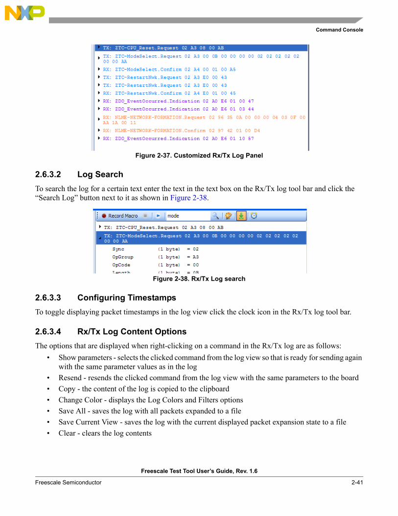
Command Console
Freescale Test Tool User’s Guide, Rev. 1.6
Freescale Semiconductor 2-41
Figure 2-37. Customized Rx/Tx Log Panel
2.6.3.2 Log SearchTo search the log for a certain text enter the text in the text box on the Rx/Tx log tool bar and click the “Search Log” button next to it as shown in Figure 2-38.
Figure 2-38. Rx/Tx Log search
2.6.3.3 Configuring TimestampsTo toggle displaying packet timestamps in the log view click the clock icon in the Rx/Tx log tool bar.
2.6.3.4 Rx/Tx Log Content OptionsThe options that are displayed when right-clicking on a command in the Rx/Tx log are as follows:
• Show parameters - selects the clicked command from the log view so that is ready for sending again with the same parameter values as in the log
• Resend - resends the clicked command from the log view with the same parameters to the board• Copy - the content of the log is copied to the clipboard• Change Color - displays the Log Colors and Filters options• Save All - saves the log with all packets expanded to a file• Save Current View - saves the log with the current displayed packet expansion state to a file• Clear - clears the log contents

Command Console
Freescale Test Tool User’s Guide, Rev. 1.6
2-42 Freescale Semiconductor
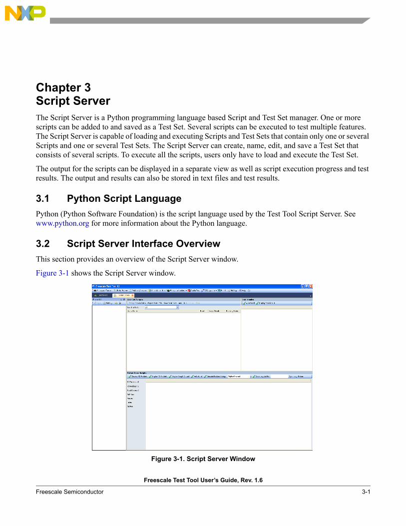
Freescale Test Tool User’s Guide, Rev. 1.6
Freescale Semiconductor 3-1
Chapter 3 Script ServerThe Script Server is a Python programming language based Script and Test Set manager. One or more scripts can be added to and saved as a Test Set. Several scripts can be executed to test multiple features. The Script Server is capable of loading and executing Scripts and Test Sets that contain only one or several Scripts and one or several Test Sets. The Script Server can create, name, edit, and save a Test Set that consists of several scripts. To execute all the scripts, users only have to load and execute the Test Set.
The output for the scripts can be displayed in a separate view as well as script execution progress and test results. The output and results can also be stored in text files and test results.
3.1 Python Script LanguagePython (Python Software Foundation) is the script language used by the Test Tool Script Server. See www.python.org for more information about the Python language.
3.2 Script Server Interface OverviewThis section provides an overview of the Script Server window.
Figure 3-1 shows the Script Server window.
Figure 3-1. Script Server Window
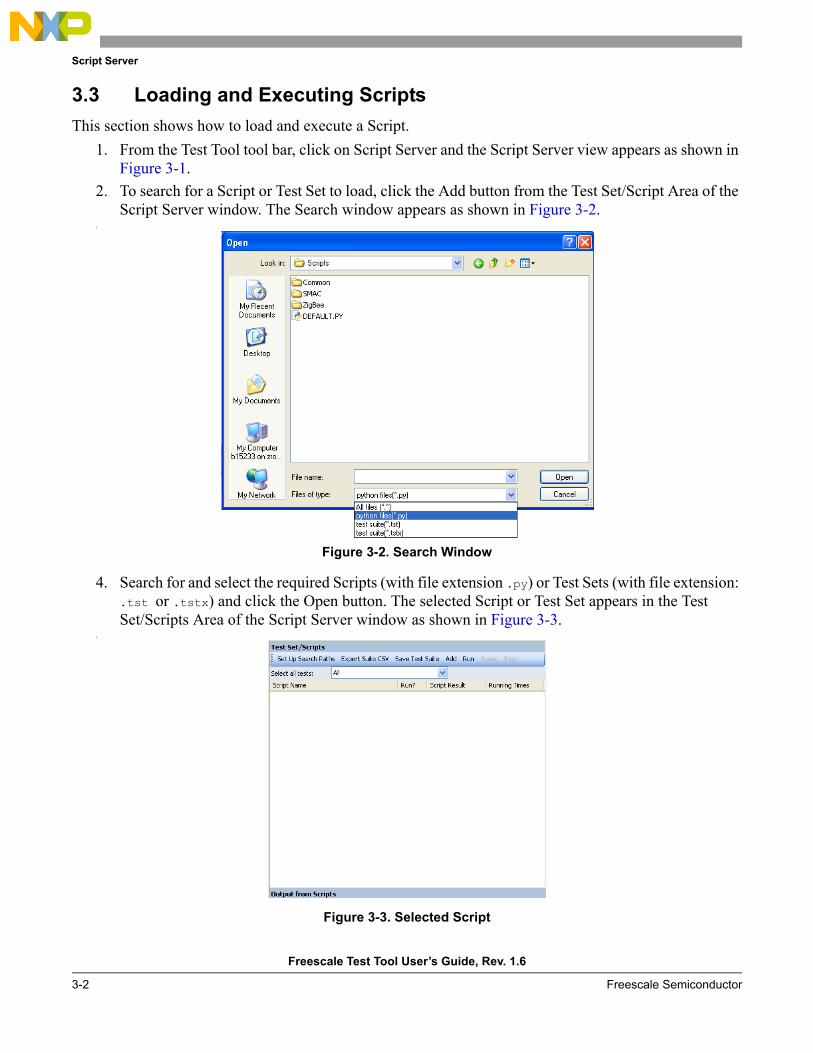
Script Server
Freescale Test Tool User’s Guide, Rev. 1.6
3-2 Freescale Semiconductor
3.3 Loading and Executing ScriptsThis section shows how to load and execute a Script.
1. From the Test Tool tool bar, click on Script Server and the Script Server view appears as shown in Figure 3-1.
2. To search for a Script or Test Set to load, click the Add button from the Test Set/Script Area of the Script Server window. The Search window appears as shown in Figure 3-2.
3.
Figure 3-2. Search Window
4. Search for and select the required Scripts (with file extension .py) or Test Sets (with file extension: .tst or .tstx) and click the Open button. The selected Script or Test Set appears in the Test Set/Scripts Area of the Script Server window as shown in Figure 3-3.
5.
Figure 3-3. Selected Script
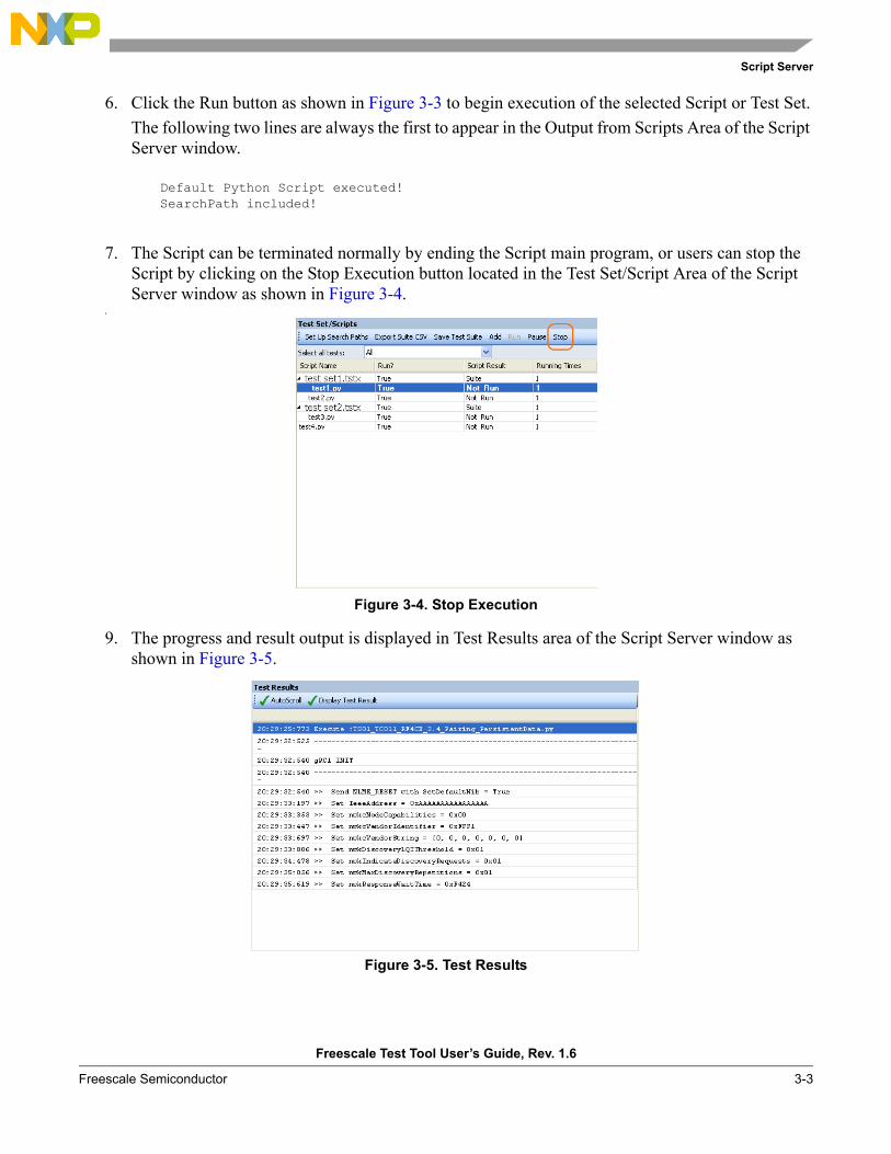
Script Server
Freescale Test Tool User’s Guide, Rev. 1.6
Freescale Semiconductor 3-3
6. Click the Run button as shown in Figure 3-3 to begin execution of the selected Script or Test Set.The following two lines are always the first to appear in the Output from Scripts Area of the Script Server window.
Default Python Script executed!SearchPath included!
7. The Script can be terminated normally by ending the Script main program, or users can stop the Script by clicking on the Stop Execution button located in the Test Set/Script Area of the Script Server window as shown in Figure 3-4.
8.
Figure 3-4. Stop Execution
9. The progress and result output is displayed in Test Results area of the Script Server window as shown in Figure 3-5.
Figure 3-5. Test Results
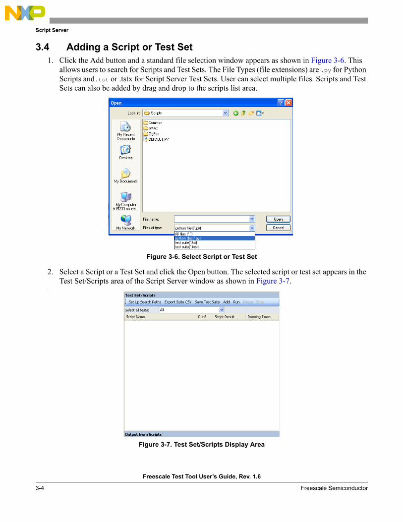
Script Server
Freescale Test Tool User’s Guide, Rev. 1.6
3-4 Freescale Semiconductor
3.4 Adding a Script or Test Set1. Click the Add button and a standard file selection window appears as shown in Figure 3-6. This
allows users to search for Scripts and Test Sets. The File Types (file extensions) are .py for Python Scripts and.tst or .tstx for Script Server Test Sets. User can select multiple files. Scripts and Test Sets can also be added by drag and drop to the scripts list area.
Figure 3-6. Select Script or Test Set
2. Select a Script or a Test Set and click the Open button. The selected script or test set appears in the Test Set/Scripts area of the Script Server window as shown in Figure 3-7.
3.
Figure 3-7. Test Set/Scripts Display Area
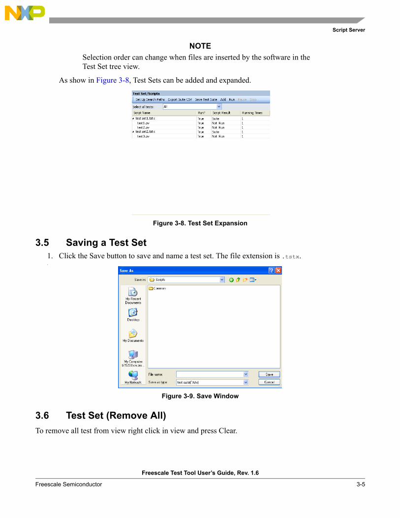
Script Server
Freescale Test Tool User’s Guide, Rev. 1.6
Freescale Semiconductor 3-5
NOTESelection order can change when files are inserted by the software in the Test Set tree view.
As show in Figure 3-8, Test Sets can be added and expanded.
Figure 3-8. Test Set Expansion
3.5 Saving a Test Set1. Click the Save button to save and name a test set. The file extension is .tstx.2.
Figure 3-9. Save Window
3.6 Test Set (Remove All) To remove all test from view right click in view and press Clear.
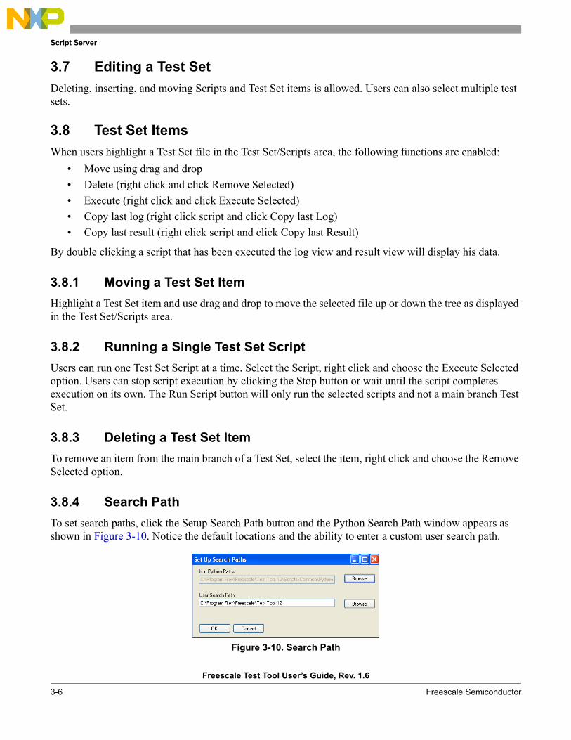
Script Server
Freescale Test Tool User’s Guide, Rev. 1.6
3-6 Freescale Semiconductor
3.7 Editing a Test SetDeleting, inserting, and moving Scripts and Test Set items is allowed. Users can also select multiple test sets.
3.8 Test Set ItemsWhen users highlight a Test Set file in the Test Set/Scripts area, the following functions are enabled:
• Move using drag and drop• Delete (right click and click Remove Selected)• Execute (right click and click Execute Selected)• Copy last log (right click script and click Copy last Log)• Copy last result (right click script and click Copy last Result)
By double clicking a script that has been executed the log view and result view will display his data.
3.8.1 Moving a Test Set ItemHighlight a Test Set item and use drag and drop to move the selected file up or down the tree as displayed in the Test Set/Scripts area.
3.8.2 Running a Single Test Set ScriptUsers can run one Test Set Script at a time. Select the Script, right click and choose the Execute Selected option. Users can stop script execution by clicking the Stop button or wait until the script completes execution on its own. The Run Script button will only run the selected scripts and not a main branch Test Set.
3.8.3 Deleting a Test Set ItemTo remove an item from the main branch of a Test Set, select the item, right click and choose the Remove Selected option.
3.8.4 Search PathTo set search paths, click the Setup Search Path button and the Python Search Path window appears as shown in Figure 3-10. Notice the default locations and the ability to enter a custom user search path.
Figure 3-10. Search Path
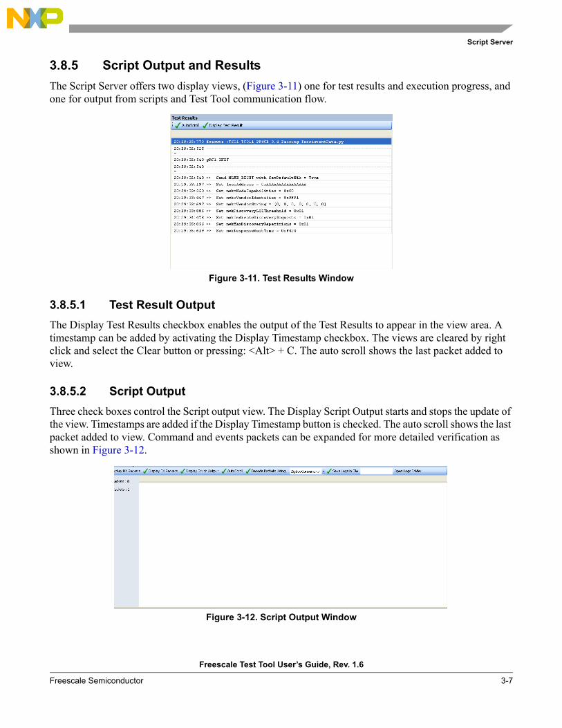
Script Server
Freescale Test Tool User’s Guide, Rev. 1.6
Freescale Semiconductor 3-7
3.8.5 Script Output and ResultsThe Script Server offers two display views, (Figure 3-11) one for test results and execution progress, and one for output from scripts and Test Tool communication flow.
Figure 3-11. Test Results Window
3.8.5.1 Test Result OutputThe Display Test Results checkbox enables the output of the Test Results to appear in the view area. A timestamp can be added by activating the Display Timestamp checkbox. The views are cleared by right click and select the Clear button or pressing: <Alt> + C. The auto scroll shows the last packet added to view.
3.8.5.2 Script OutputThree check boxes control the Script output view. The Display Script Output starts and stops the update of the view. Timestamps are added if the Display Timestamp button is checked. The auto scroll shows the last packet added to view. Command and events packets can be expanded for more detailed verification as shown in Figure 3-12.
Figure 3-12. Script Output Window
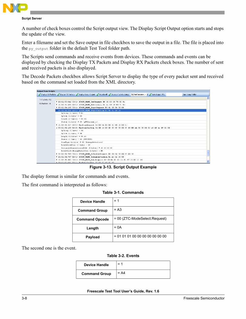
Script Server
Freescale Test Tool User’s Guide, Rev. 1.6
3-8 Freescale Semiconductor
A number of check boxes control the Script output view. The Display Script Output option starts and stops the update of the view.
Enter a filename and set the Save output in file checkbox to save the output in a file. The file is placed into the py_output folder in the default Test Tool folder path.
The Scripts send commands and receive events from devices. These commands and events can be displayed by checking the Display TX Packets and Display RX Packets check boxes. The number of sent and received packets is also displayed.
The Decode Packets checkbox allows Script Server to display the type of every packet sent and received based on the command set loaded from the XML directory.
Figure 3-13. Script Output Example
The display format is similar for commands and events.
The first command is interpreted as follows:
The second one is the event.
Table 3-1. Commands
Device Handle = 1
Command Group = A3
Command Opcode = 00 (ZTC-ModeSelect.Request)
Length = 0A
Payload = 01 01 01 00 00 00 00 00 00 00
Table 3-2. Events
Device Handle = 1
Command Group = A4
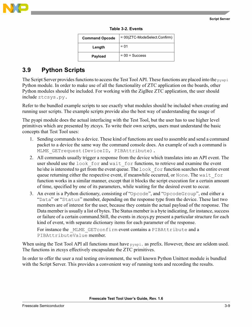
Script Server
Freescale Test Tool User’s Guide, Rev. 1.6
Freescale Semiconductor 3-9
3.9 Python ScriptsThe Script Server provides functions to access the Test Tool API. These functions are placed into the pyapi Python module. In order to make use of all the functionality of ZTC application on the boards, other Python modules should be included. For working with the ZigBee ZTC application, the user should include ztcsys.py.
Refer to the bundled example scripts to see exactly what modules should be included when creating and running user scripts. The example scripts provide also the best way of understanding the usage of
The pyapi module does the actual interfacing with the Test Tool, but the user has to use higher level primitives which are presented by ztcsys. To write their own scripts, users must understand the basic concepts that Test Tool uses:
1. Sending commands to a device. These kind of functions are used to assemble and send a command packet to a device the same way the command console does. An example of such a command is MLME_GETrequest(DeviceID, PIBAttribute).
2. All commands usually trigger a response from the device which translates into an API event. The user should use the look_for and wait_for functions, to retrieve and examine the event he/she is interested to get from the event queue. The look_for function searches the entire event queue returning either the respective event, if meanwhile occurred, or None. The wait_for function works in a similar manner, except that it blocks the script execution for a certain amount of time, specified by one of its parameters, while waiting for the desired event to occur.
3. An event is a Python dictionary, consisting of “Opcode”, and “OpcodeGroup”, end either a “Data” or “Status” member, depending on the response type from the device. These last two members are of interest for the user, because they contain the actual payload of the response. The Data member is usually a list of bytes. The Status member is a byte indicating, for instance, success or failure of a certain command.Still, the events in ztcsys.py present a particular structure for each kind of event, with separate dictionary items for each parameter of the response.For instance the _MLME_GETconfirm event contains a PIBAttribute and a PIBAttributeValue member.
When using the Test Tool API all functions must have pyapi. as prefix. However, these are seldom used. The functions in ztcsys effectively encapsulate the ZTC primitives.
In order to offer the user a real testing environment, the well known Python Unittest module is bundled with the Script Server. This provides a convenient way of running tests and recording the results.
Command Opcode = 00(ZTC-ModeSelect.Confirm)
Length = 01
Payload = 00 = Success
Table 3-2. Events
Script Server
Freescale Test Tool User’s Guide, Rev. 1.6
3-10 Freescale Semiconductor
3.9.1 Communication Between Scripts and DevicesThe devices can be connected by UART/USB or Winsockets. The devices are listed in the Test Tool List of Devices.
To communicate to a device from a Script, the Script must start the device and retrieve a handle.
For example: LocalDeviceHandle = pyapi.StartDevice(DEV_ZIGBEE)
Table 3-3.
StartDevice Starts the communication with the device and returns a handle to be used for communication.
Returns 0 on failure, else a handle to the device.
For example: LocalDevice = pyapi.StartDevice(0)
StopDevice Stops the communication with the device and releases the handle.Parameter unsigned short DeviceIdReturns 0 (false) on failure , else 1 (true)
For example:
pyapi.StopDevice(LocalDevice)SendCommand.
3.9.1.1 SendCommandThe SendCommand sends a command to a device.Parameters unsigned short DevId
unsigned char *pCmdunsigned short Length
Parameter description DevId is the Test Tool API for a device, the handle value is returned calling pyapi.StartDevice.pCmd is a pointer to an array of bytes holding the command.Length is the number of bytes in the command buffer pCmd.
Return value Returns true (1) on success , false (0) on failure.
Script Server
Freescale Test Tool User’s Guide, Rev. 1.6
Freescale Semiconductor 3-11
3.9.1.2 SendToolCommandThe SendToolCommand sends a command to all or one Test Tool API clients – see CallBack.Function RegisterToolCommands. Parameters unsigned short DevId
unsigned char *pCmdunsigned short Length
Parameter description If DevId = 0 the command is send to all internal Test Tool API Clients. If DevId>0 the command is send to the device with the specified handle value. pCmd is a pointer to an array of bytes holding the command. Length is the number of bytes in the command buffer pCmd.
NOTEThe handle value was returned calling pyapi.StartDevice:
Return value Returns true (1) on successFalse (0) on failure.
3.9.1.3 SendToolEventFunction SendToolEvent.Parameters unsigned short DevId
unsigned char *pCmdunsigned short Length
Parameter description DevId = 0. Values above 0 is used by devices or managed by the Test Tool API. pEvent is a pointer to an array of bytes holding the event. Length is the number of bytes in the command buffer pEvent.
Return value Returns true (1) on successFalse (0) on failure.
3.9.2 Callback FunctionsThis group of functions must be used to receive events sent by the Test Tool API. A call can look like the following:
pyapi.RegisterToolEvents(__ToolEvent)
All Events have three parameters: • unsigned short DevId• unsigned char *pData • unsigned short Length.

Script Server
Freescale Test Tool User’s Guide, Rev. 1.6
3-12 Freescale Semiconductor
All Callback Functions takes a Handle (pointer) to a CallBack function (PyObject).
3.9.2.1 Device EventsStart and stop receiving events from a device.RegisterDeviceEvents Use to get events from a device, remote or internal.Parameter Void * pFuncParameter Description pFunc must be a pointer to a callback function.Return Value Returns true (1) on success , false (0) on failure.
DeregisterDeviceEvents Use to stop receiving events from the devices.Parameter Void * pFuncParameter Description pFunc must be a pointer to a callback function.Return Value Returns true (1) on success , false (0) on failure.
3.9.2.2 Tool EventsRegisterToolEvents Use to get Test Tool events, remote or internal.Parameter Void * pFuncParameter Description pFunc must be a pointer to a callback function.Return Value Returns true (1) on success , false (0) on failure.
DeregisterToolEvents Use to stop getting Test Tool events.Parameter Void * pFuncParameter Description pFunc must be a pointer to a callback function.Return Value Returns true (1) on success , false (0) on failure.
3.9.2.3 Tool CommandsRegisterToolCommandsUse to receive Test Tool commands, remote or internal.Parameter Void * pFuncParameter Description pFunc must be a pointer to a callback function.Return Value Returns true (1) on success , false (0) on failure.
DeRegisterToolCommands Use to stop receiving Test Tool commands.Parameter Void * pFuncParameter Description pFunc must be a pointer to a callback function.Return Value Returns true (1) on success , false (0) on failure.
Script Server
Freescale Test Tool User’s Guide, Rev. 1.6
Freescale Semiconductor 3-13
3.9.3 Test Result from Python ScriptTwo functions are used to display output from Scripts in the Test Result view.SetTestResult Sets the result of a ScriptParameter integerResult values PyTR_Failure = 0x00
PyTR_Success = 0x01PyTR_Unknown = 0x02PyTR_NoResult = 0x03above this = Failure
WriteTestResultWriteTestResult Used to print information in text format in the Test Result view.Parameter Char * TextString
3.9.4 Python Script Print OutputThe Python standard print function can be used to display tests in the Script output area of the Script Server window. Error prints are also displayed. Errors in Scripts are displayed with a description of the error, the file, and the line (as an aid for where to look for the error).

Script Server
Freescale Test Tool User’s Guide, Rev. 1.6
3-14 Freescale Semiconductor
Freescale Test Tool User’s Guide, Rev. 1.6
Freescale Semiconductor 4-1
Chapter 4 Firmware LoadersThis chapter describes the two firmware loaders that come with the Test Tool, the HCS08 Firmware Loader and the MC1322x Firmware Loader. They can flash new firmware into Freescale ZigBee evaluation boards and allow users to flash different application code into these boards from Test Tool without the need for other software.
4.1 Introducing the Firmware LoadersThe HCS08 Firmware Loader only operates with Freescale’s HCS08 architecture microcontroller based boards such as the 1321x-SRB, 1321x-NCB, MC1320x-QE128, or MC1323x boards. The HCS08 Firmware Loader only supports the S-record (.S19) files and uses the USB BDM Multilink device to upload the content of the .s19 files into microcontroller’s FLASH.
The MC1322x Firmware Loader only operates with Freescale’s 1322x-NN, 1322x-SN, 1322x-SRB, 1322x-LPB and 1322x-USB development boards, which are based on Freescale’s MC1322x ARM7 based third-generation ZigBee platform which incorporate a complete, low power, 2.4 GHz radio frequency transceiver, 32-bit ARM7 core based MCU, and other features in a single package.
The MC1322x Firmware Loader only supports binary (.bin) files and makes use of the ARM7 microcontroller’s serial communication interface and the embedded bootloader in ROM, so no additional hardware is required, with the exception of the communication cable.
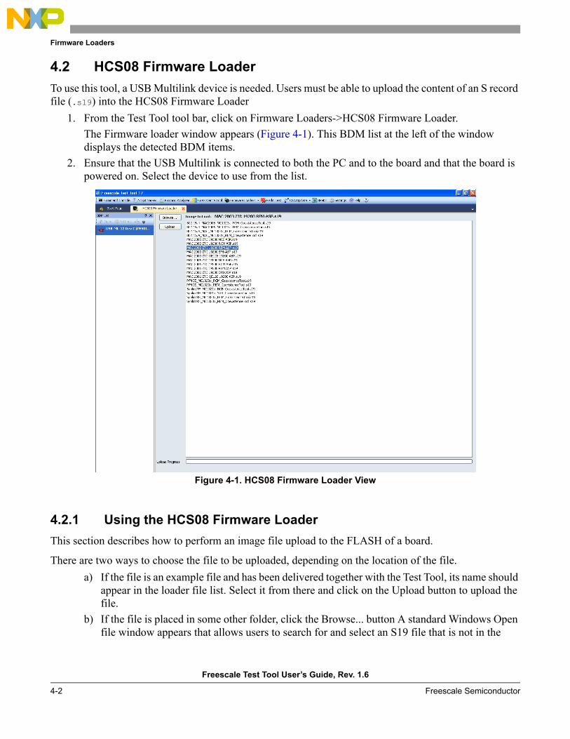
Firmware Loaders
Freescale Test Tool User’s Guide, Rev. 1.6
4-2 Freescale Semiconductor
4.2 HCS08 Firmware LoaderTo use this tool, a USB Multilink device is needed. Users must be able to upload the content of an S record file (.s19) into the HCS08 Firmware Loader
1. From the Test Tool tool bar, click on Firmware Loaders->HCS08 Firmware Loader.The Firmware loader window appears (Figure 4-1). This BDM list at the left of the window displays the detected BDM items.
2. Ensure that the USB Multilink is connected to both the PC and to the board and that the board is powered on. Select the device to use from the list.
Figure 4-1. HCS08 Firmware Loader View
4.2.1 Using the HCS08 Firmware LoaderThis section describes how to perform an image file upload to the FLASH of a board.
There are two ways to choose the file to be uploaded, depending on the location of the file.a) If the file is an example file and has been delivered together with the Test Tool, its name should
appear in the loader file list. Select it from there and click on the Upload button to upload the file.
b) If the file is placed in some other folder, click the Browse... button A standard Windows Open file window appears that allows users to search for and select an S19 file that is not in the
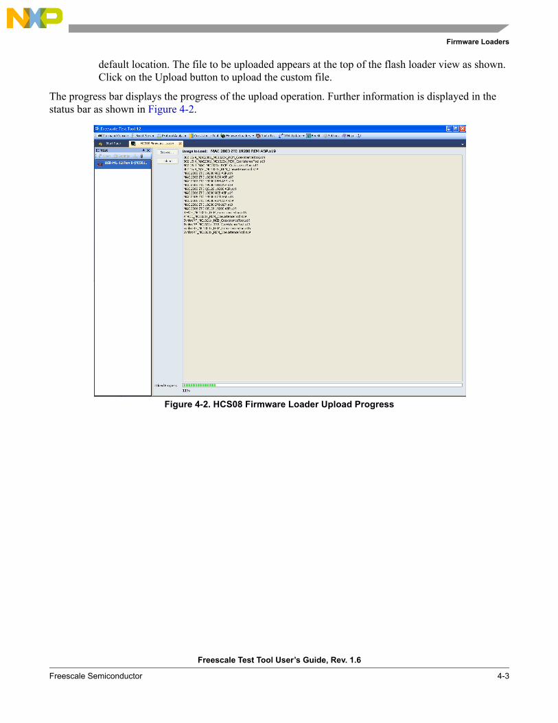
Firmware Loaders
Freescale Test Tool User’s Guide, Rev. 1.6
Freescale Semiconductor 4-3
default location. The file to be uploaded appears at the top of the flash loader view as shown. Click on the Upload button to upload the custom file.
The progress bar displays the progress of the upload operation. Further information is displayed in the status bar as shown in Figure 4-2.
Figure 4-2. HCS08 Firmware Loader Upload Progress
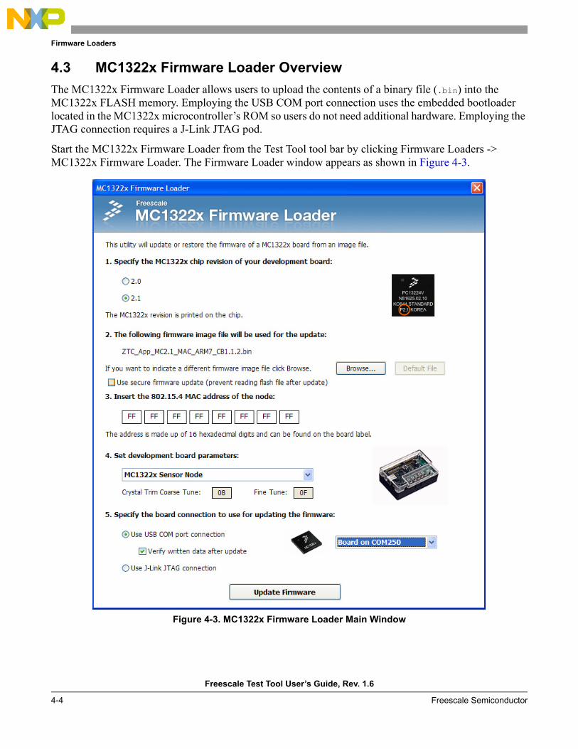
Firmware Loaders
Freescale Test Tool User’s Guide, Rev. 1.6
4-4 Freescale Semiconductor
4.3 MC1322x Firmware Loader OverviewThe MC1322x Firmware Loader allows users to upload the contents of a binary file (.bin) into the MC1322x FLASH memory. Employing the USB COM port connection uses the embedded bootloader located in the MC1322x microcontroller’s ROM so users do not need additional hardware. Employing the JTAG connection requires a J-Link JTAG pod.
Start the MC1322x Firmware Loader from the Test Tool tool bar by clicking Firmware Loaders -> MC1322x Firmware Loader. The Firmware Loader window appears as shown in Figure 4-3.
Figure 4-3. MC1322x Firmware Loader Main Window
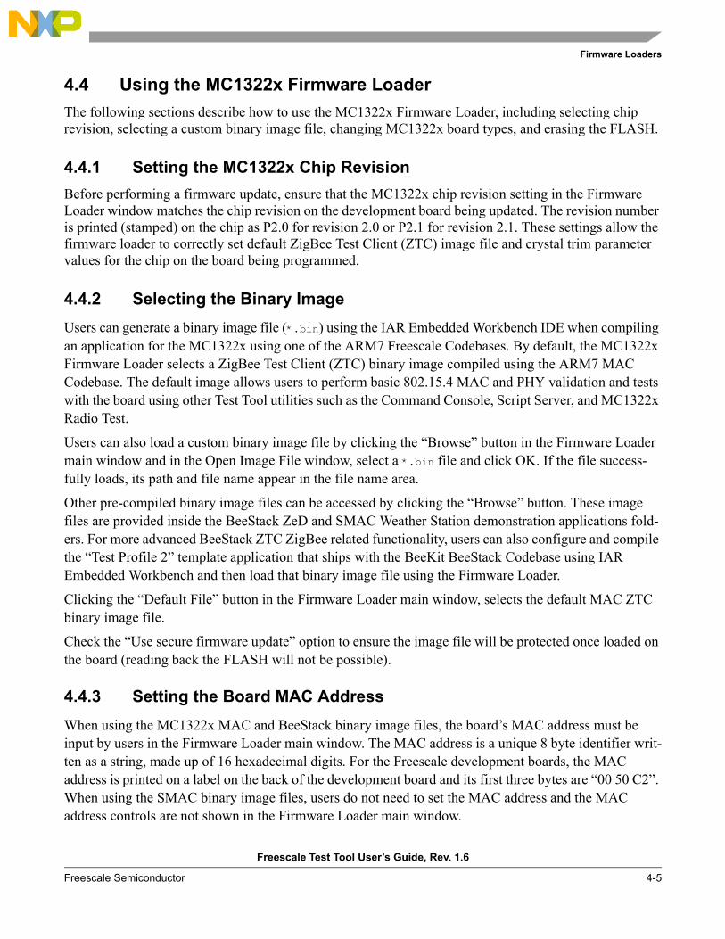
Firmware Loaders
Freescale Test Tool User’s Guide, Rev. 1.6
Freescale Semiconductor 4-5
4.4 Using the MC1322x Firmware LoaderThe following sections describe how to use the MC1322x Firmware Loader, including selecting chip revision, selecting a custom binary image file, changing MC1322x board types, and erasing the FLASH.
4.4.1 Setting the MC1322x Chip RevisionBefore performing a firmware update, ensure that the MC1322x chip revision setting in the Firmware Loader window matches the chip revision on the development board being updated. The revision number is printed (stamped) on the chip as P2.0 for revision 2.0 or P2.1 for revision 2.1. These settings allow the firmware loader to correctly set default ZigBee Test Client (ZTC) image file and crystal trim parameter values for the chip on the board being programmed.
4.4.2 Selecting the Binary ImageUsers can generate a binary image file (*.bin) using the IAR Embedded Workbench IDE when compiling an application for the MC1322x using one of the ARM7 Freescale Codebases. By default, the MC1322x Firmware Loader selects a ZigBee Test Client (ZTC) binary image compiled using the ARM7 MAC Codebase. The default image allows users to perform basic 802.15.4 MAC and PHY validation and tests with the board using other Test Tool utilities such as the Command Console, Script Server, and MC1322x Radio Test.
Users can also load a custom binary image file by clicking the “Browse” button in the Firmware Loader main window and in the Open Image File window, select a *.bin file and click OK. If the file success-fully loads, its path and file name appear in the file name area.
Other pre-compiled binary image files can be accessed by clicking the “Browse” button. These image files are provided inside the BeeStack ZeD and SMAC Weather Station demonstration applications fold-ers. For more advanced BeeStack ZTC ZigBee related functionality, users can also configure and compile the “Test Profile 2” template application that ships with the BeeKit BeeStack Codebase using IAR Embedded Workbench and then load that binary image file using the Firmware Loader.
Clicking the “Default File” button in the Firmware Loader main window, selects the default MAC ZTC binary image file.
Check the “Use secure firmware update” option to ensure the image file will be protected once loaded on the board (reading back the FLASH will not be possible).
4.4.3 Setting the Board MAC AddressWhen using the MC1322x MAC and BeeStack binary image files, the board’s MAC address must be input by users in the Firmware Loader main window. The MAC address is a unique 8 byte identifier writ-ten as a string, made up of 16 hexadecimal digits. For the Freescale development boards, the MAC address is printed on a label on the back of the development board and its first three bytes are “00 50 C2”. When using the SMAC binary image files, users do not need to set the MAC address and the MAC address controls are not shown in the Firmware Loader main window.
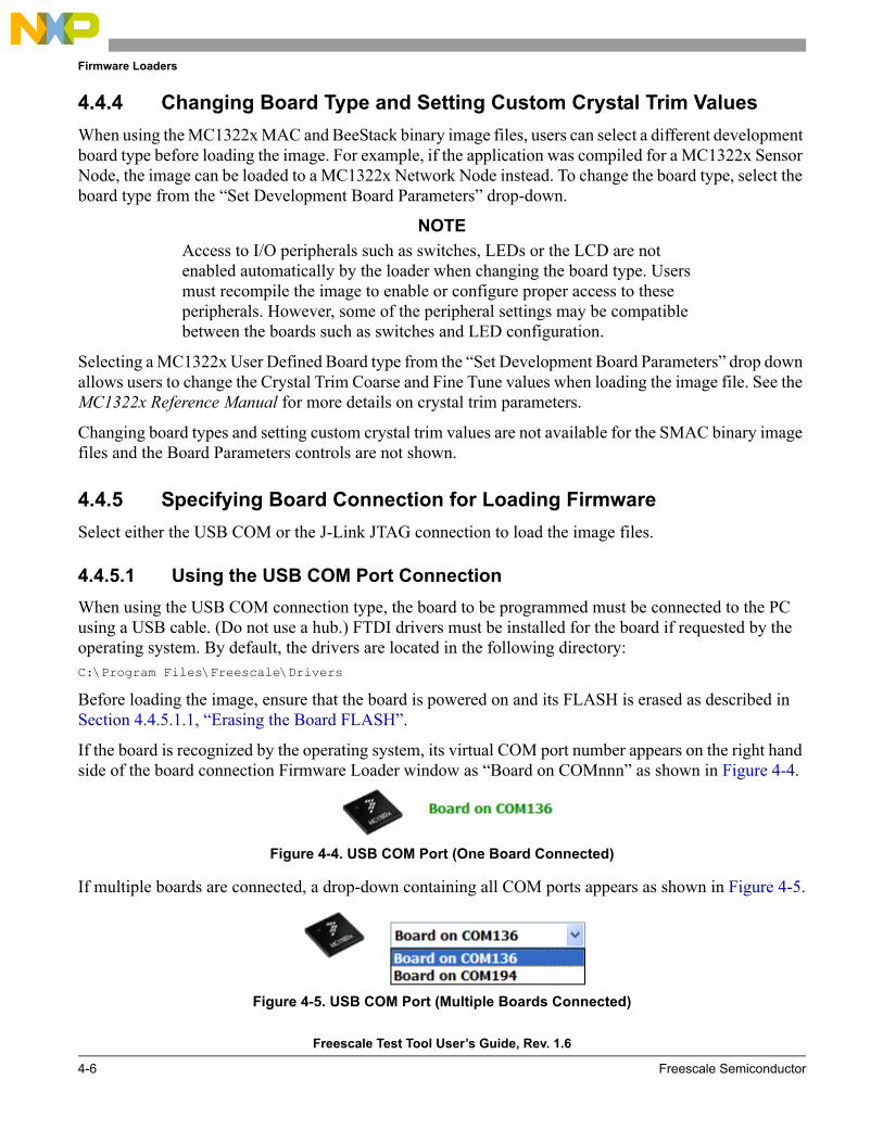
Firmware Loaders
Freescale Test Tool User’s Guide, Rev. 1.6
4-6 Freescale Semiconductor
4.4.4 Changing Board Type and Setting Custom Crystal Trim ValuesWhen using the MC1322x MAC and BeeStack binary image files, users can select a different development board type before loading the image. For example, if the application was compiled for a MC1322x Sensor Node, the image can be loaded to a MC1322x Network Node instead. To change the board type, select the board type from the “Set Development Board Parameters” drop-down.
NOTEAccess to I/O peripherals such as switches, LEDs or the LCD are not enabled automatically by the loader when changing the board type. Users must recompile the image to enable or configure proper access to these peripherals. However, some of the peripheral settings may be compatible between the boards such as switches and LED configuration.
Selecting a MC1322x User Defined Board type from the “Set Development Board Parameters” drop down allows users to change the Crystal Trim Coarse and Fine Tune values when loading the image file. See the MC1322x Reference Manual for more details on crystal trim parameters.
Changing board types and setting custom crystal trim values are not available for the SMAC binary image files and the Board Parameters controls are not shown.
4.4.5 Specifying Board Connection for Loading FirmwareSelect either the USB COM or the J-Link JTAG connection to load the image files.
4.4.5.1 Using the USB COM Port ConnectionWhen using the USB COM connection type, the board to be programmed must be connected to the PC using a USB cable. (Do not use a hub.) FTDI drivers must be installed for the board if requested by the operating system. By default, the drivers are located in the following directory:C:\Program Files\Freescale\Drivers
Before loading the image, ensure that the board is powered on and its FLASH is erased as described in Section 4.4.5.1.1, “Erasing the Board FLASH”.
If the board is recognized by the operating system, its virtual COM port number appears on the right hand side of the board connection Firmware Loader window as “Board on COMnnn” as shown in Figure 4-4.
Figure 4-4. USB COM Port (One Board Connected)
If multiple boards are connected, a drop-down containing all COM ports appears as shown in Figure 4-5.
Figure 4-5. USB COM Port (Multiple Boards Connected)

Firmware Loaders
Freescale Test Tool User’s Guide, Rev. 1.6
Freescale Semiconductor 4-7
Choose the COM port of the board that is going to be programmed or turn off the other boards until only one COM number is shown. If no boards are connected to the system, if they are turned off, or the drivers for the boards are not installed, the “No board detected” message appears as shown in Figure 4-6.
Figure 4-6. USB COM Port (No Board Detected)
Check the “Verify written date after update” option to perform a verification that the data that has been uploaded via the USB COM connection has been correctly written to the board. After updating the firmware, the bootloader program reads the written data and reports if there are differences between what was written and what was read afterwards.
4.4.5.1.1 Erasing the Board FLASH
Before trying to upload a binary image to the board using the USB COM connection, ensure that the FLASH is erased. Otherwise, communication with the board will not be initiated.
To erase the FLASH, perform the following tasks:1. Use 2 (two) jumpers and short together the pin pairs marked VREFH (ADC2_VrefH) and VREFL
(ADC2_VrefL) on the board. These pin pairs are clearly marked on the board.2. Press the Reset Switch on the board and wait 5 seconds.3. Unplug the board from the USB port.4. Remove the two jumpers.5. Plug the board back in the USB port.6. Press the Reset Switch on the board again.
4.4.5.2 Using the J-Link JTAG Port ConnectionWhen using the J-Link JTAG connection, a J-Link JTAG pod must be connected to the PC and the board must be attached to the JTAG pod using the JTAG port connector. When the JTAG pod is connected to the PC, the Firmware Loader message “J-Link is active” appears as shown in Figure 4-7.
Figure 4-7. J-Link JTAG Connected to the PC
The board attached to the JTAG pod must be powered on, but it does not need to be connected to the PC with the USB cable.
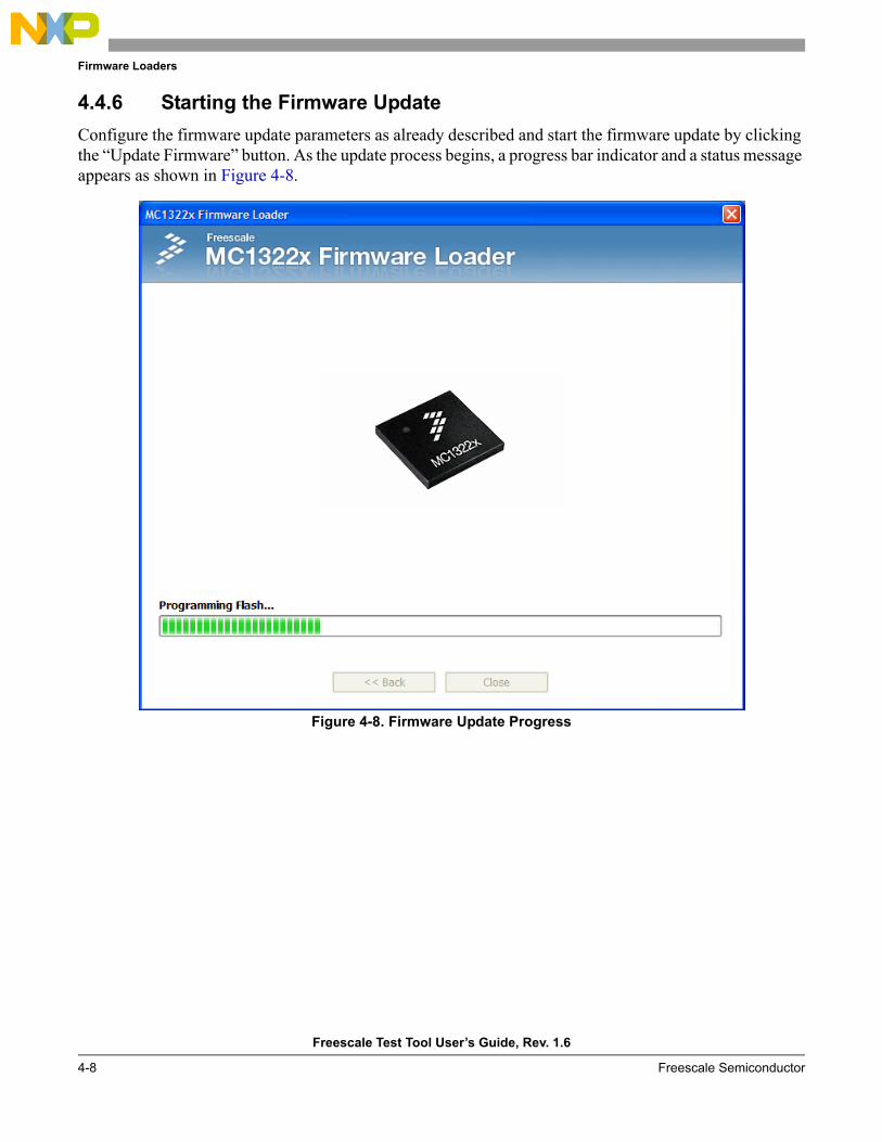
Firmware Loaders
Freescale Test Tool User’s Guide, Rev. 1.6
4-8 Freescale Semiconductor
4.4.6 Starting the Firmware UpdateConfigure the firmware update parameters as already described and start the firmware update by clicking the “Update Firmware” button. As the update process begins, a progress bar indicator and a status message appears as shown in Figure 4-8.
Figure 4-8. Firmware Update Progress
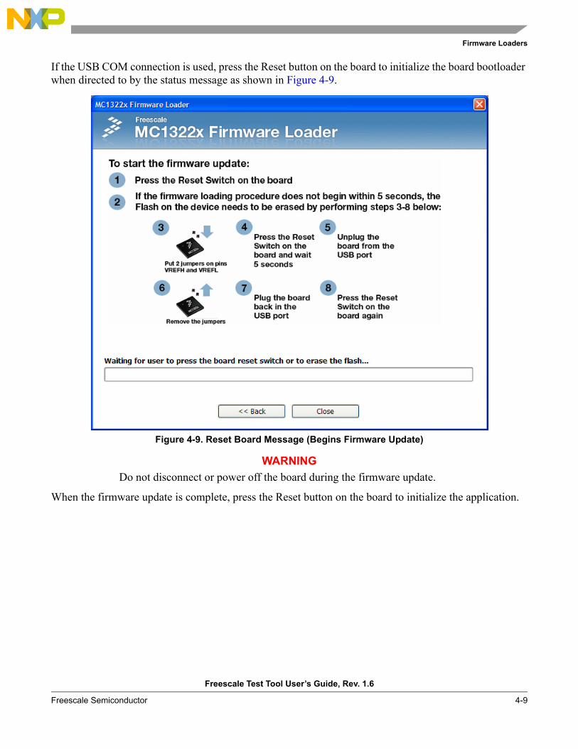
Firmware Loaders
Freescale Test Tool User’s Guide, Rev. 1.6
Freescale Semiconductor 4-9
If the USB COM connection is used, press the Reset button on the board to initialize the board bootloader when directed to by the status message as shown in Figure 4-9.
Figure 4-9. Reset Board Message (Begins Firmware Update)
WARNINGDo not disconnect or power off the board during the firmware update.
When the firmware update is complete, press the Reset button on the board to initialize the application.

Firmware Loaders
Freescale Test Tool User’s Guide, Rev. 1.6
4-10 Freescale Semiconductor
Freescale Test Tool User’s Guide, Rev. 1.6
Freescale Semiconductor 5-1
Chapter 5 Protocol Analyzer The Protocol Analyzer view provides the ability to monitor over the air packet activity for IEEE 802.15.4 based implementations.
5.1 Protocol Stack SupportThe following protocol stacks are decoded:
• IEEE 802.15.4- 2003, MAC• IEEE 802.15.5- 2006, MAC (with predefined key based security support)• Freescale BeeStack Consumer (ZigBee RF4CE) stack (with OTA pair/key seed based security
support)— ZigBee Remote Control Application Profile— Freescale BeeStack Consumer Private Profile
5.2 Supported Hardware Sniffer DevicesTo show over the air packet activity, the Protocol Analyzer must communicate to and use a hardware 802.15.4 sniffer device connected to the PC.
The following Freescale devices are supported:• HCS08 MC1321x Analyzer
The Packet Analyzer supports the following Freescale sniffing hardware:• MC1322x USB Dongle
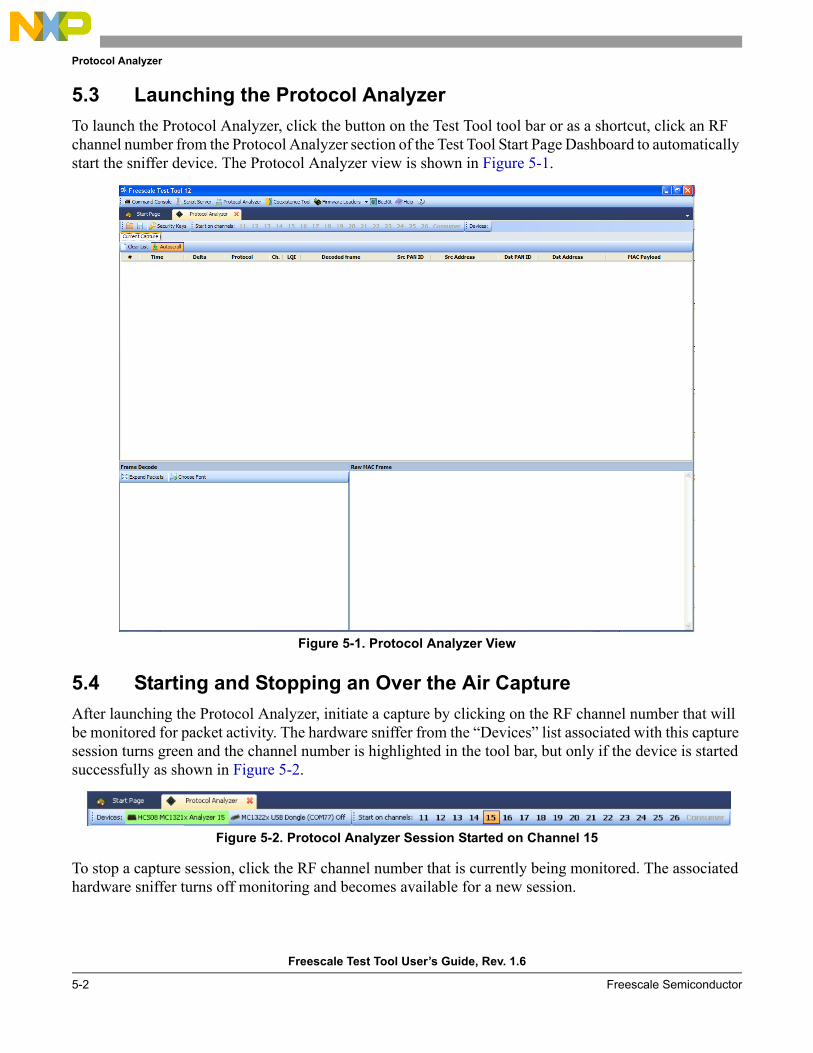
Protocol Analyzer
Freescale Test Tool User’s Guide, Rev. 1.6
5-2 Freescale Semiconductor
5.3 Launching the Protocol AnalyzerTo launch the Protocol Analyzer, click the button on the Test Tool tool bar or as a shortcut, click an RF channel number from the Protocol Analyzer section of the Test Tool Start Page Dashboard to automatically start the sniffer device. The Protocol Analyzer view is shown in Figure 5-1.
Figure 5-1. Protocol Analyzer View
5.4 Starting and Stopping an Over the Air CaptureAfter launching the Protocol Analyzer, initiate a capture by clicking on the RF channel number that will be monitored for packet activity. The hardware sniffer from the “Devices” list associated with this capture session turns green and the channel number is highlighted in the tool bar, but only if the device is started successfully as shown in Figure 5-2.
Figure 5-2. Protocol Analyzer Session Started on Channel 15
To stop a capture session, click the RF channel number that is currently being monitored. The associated hardware sniffer turns off monitoring and becomes available for a new session.
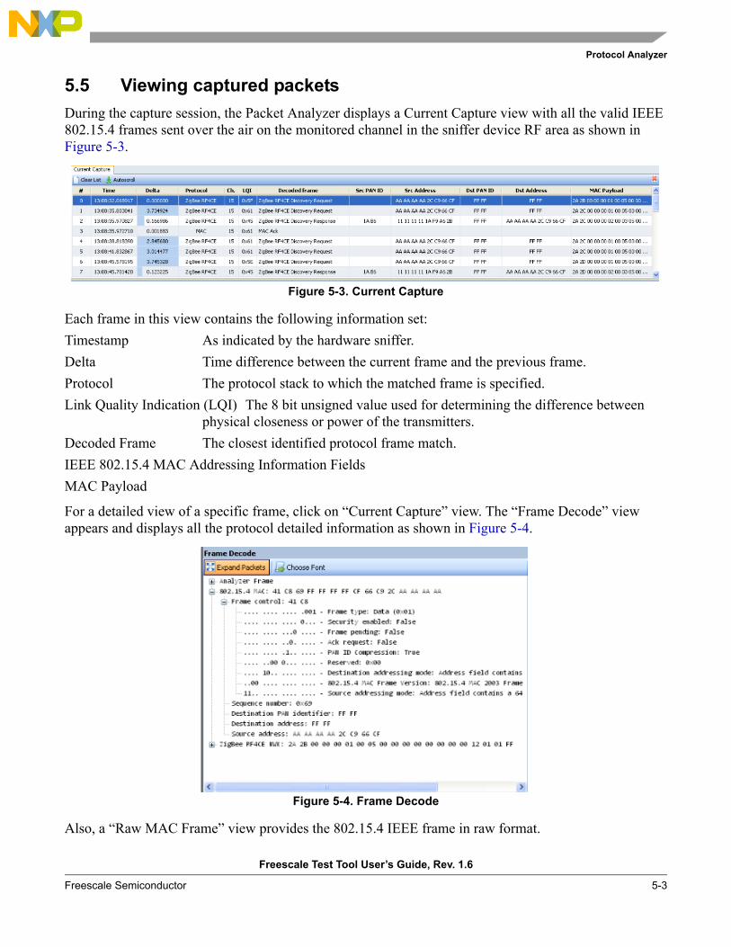
Protocol Analyzer
Freescale Test Tool User’s Guide, Rev. 1.6
Freescale Semiconductor 5-3
5.5 Viewing captured packetsDuring the capture session, the Packet Analyzer displays a Current Capture view with all the valid IEEE 802.15.4 frames sent over the air on the monitored channel in the sniffer device RF area as shown in Figure 5-3.
Figure 5-3. Current Capture
Each frame in this view contains the following information set: Timestamp As indicated by the hardware sniffer.Delta Time difference between the current frame and the previous frame.Protocol The protocol stack to which the matched frame is specified.Link Quality Indication (LQI) The 8 bit unsigned value used for determining the difference between
physical closeness or power of the transmitters.Decoded Frame The closest identified protocol frame match.IEEE 802.15.4 MAC Addressing Information FieldsMAC Payload
For a detailed view of a specific frame, click on “Current Capture” view. The “Frame Decode” view appears and displays all the protocol detailed information as shown in Figure 5-4.
Figure 5-4. Frame Decode
Also, a “Raw MAC Frame” view provides the 802.15.4 IEEE frame in raw format.
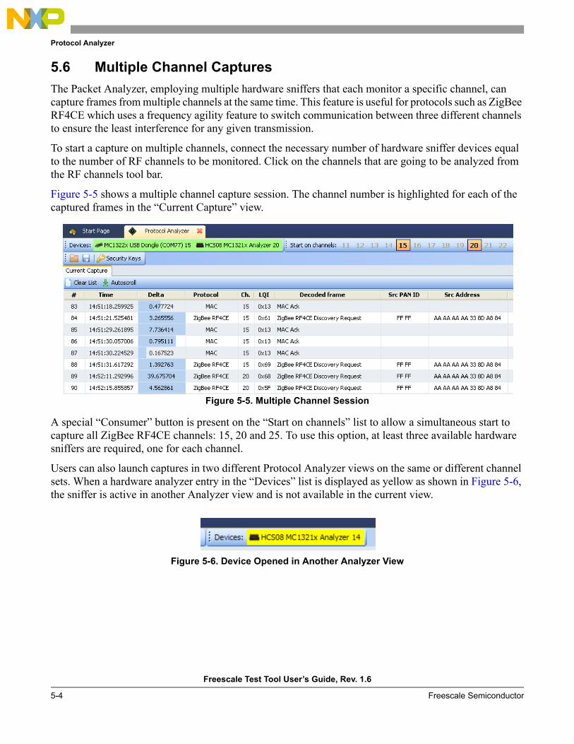
Protocol Analyzer
Freescale Test Tool User’s Guide, Rev. 1.6
5-4 Freescale Semiconductor
5.6 Multiple Channel CapturesThe Packet Analyzer, employing multiple hardware sniffers that each monitor a specific channel, can capture frames from multiple channels at the same time. This feature is useful for protocols such as ZigBee RF4CE which uses a frequency agility feature to switch communication between three different channels to ensure the least interference for any given transmission.
To start a capture on multiple channels, connect the necessary number of hardware sniffer devices equal to the number of RF channels to be monitored. Click on the channels that are going to be analyzed from the RF channels tool bar.
Figure 5-5 shows a multiple channel capture session. The channel number is highlighted for each of the captured frames in the “Current Capture” view.
Figure 5-5. Multiple Channel Session
A special “Consumer” button is present on the “Start on channels” list to allow a simultaneous start to capture all ZigBee RF4CE channels: 15, 20 and 25. To use this option, at least three available hardware sniffers are required, one for each channel.
Users can also launch captures in two different Protocol Analyzer views on the same or different channel sets. When a hardware analyzer entry in the “Devices” list is displayed as yellow as shown in Figure 5-6, the sniffer is active in another Analyzer view and is not available in the current view.
Figure 5-6. Device Opened in Another Analyzer View
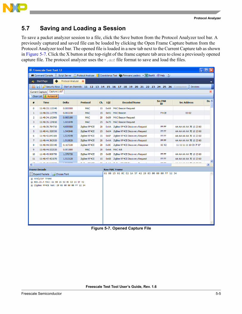
Protocol Analyzer
Freescale Test Tool User’s Guide, Rev. 1.6
Freescale Semiconductor 5-5
5.7 Saving and Loading a SessionTo save a packet analyzer session to a file, click the Save button from the Protocol Analyzer tool bar. A previously captured and saved file can be loaded by clicking the Open Frame Capture button from the Protocol Analyzer tool bar. The opened file is loaded in a new tab next to the Current Capture tab as shown in Figure 5-7. Click the X button at the top-right of the frame capture tab area to close a previously opened capture file. The protocol analyzer uses the *.dcf file format to save and load the files.
Figure 5-7. Opened Capture File
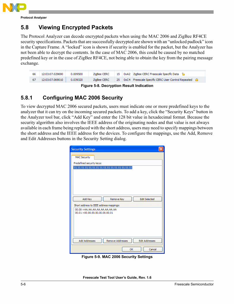
Protocol Analyzer
Freescale Test Tool User’s Guide, Rev. 1.6
5-6 Freescale Semiconductor
5.8 Viewing Encrypted PacketsThe Protocol Analyzer can decode encrypted packets when using the MAC 2006 and ZigBee RF4CE security specifications. Packets that are successfully decrypted are shown with an “unlocked padlock” icon in the Capture Frame. A “locked” icon is shown if security is enabled for the packet, but the Analyzer has not been able to decrypt the contents. In the case of MAC 2006, this could be caused by no matched predefined key or in the case of ZigBee RF4CE, not being able to obtain the key from the pairing message exchange.
Figure 5-8. Decryption Result Indication
5.8.1 Configuring MAC 2006 SecurityTo view decrypted MAC 2006 secured packets, users must indicate one or more predefined keys to the analyzer that it can try on the incoming secured packets. To add a key, click the “Security Keys” button in the Analyzer tool bar, click “Add Key” and enter the 128 bit value in hexadecimal format. Because the security algorithm also involves the IEEE address of the originating nodes and that value is not always available in each frame being replaced with the short address, users may need to specify mappings between the short address and the IEEE address for the devices. To configure the mappings, use the Add, Remove and Edit Addresses buttons in the Security Setting dialog.
Figure 5-9. MAC 2006 Security Settings
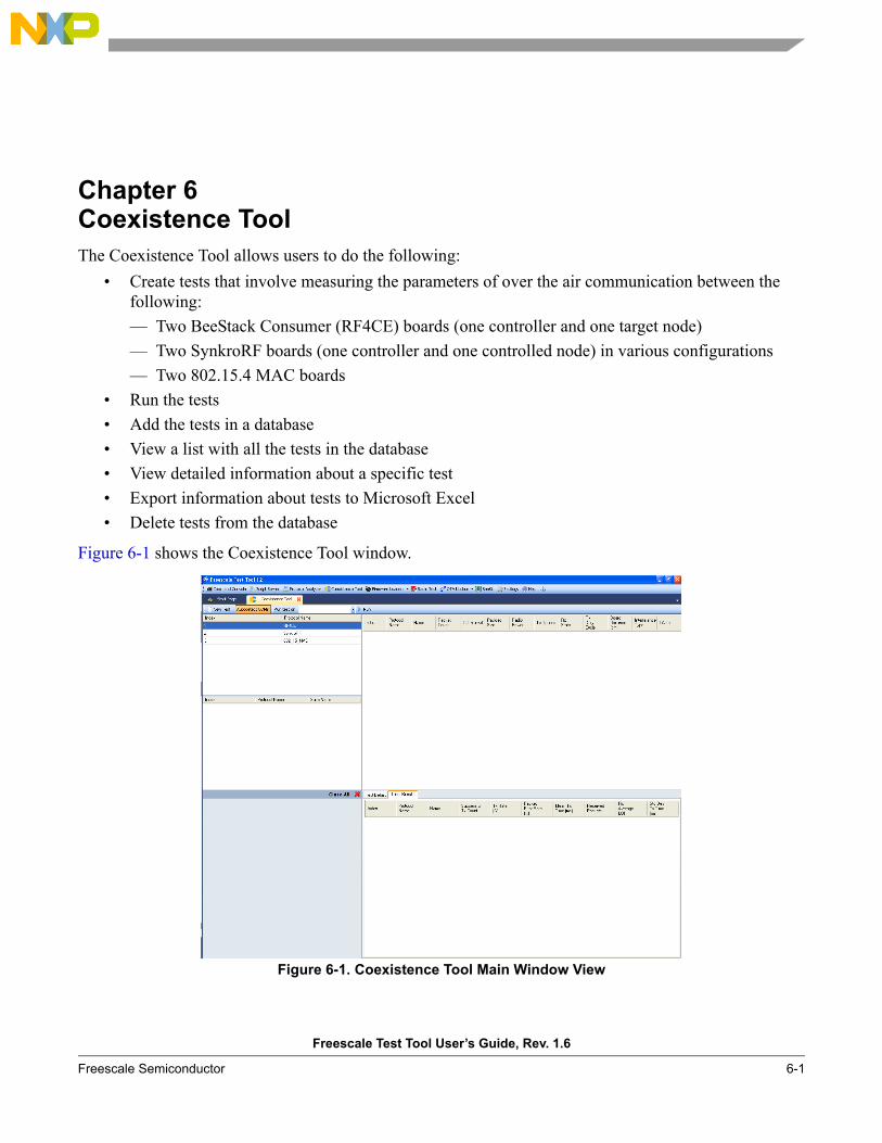
Freescale Test Tool User’s Guide, Rev. 1.6
Freescale Semiconductor 6-1
Chapter 6 Coexistence ToolThe Coexistence Tool allows users to do the following:
• Create tests that involve measuring the parameters of over the air communication between the following:— Two BeeStack Consumer (RF4CE) boards (one controller and one target node)— Two SynkroRF boards (one controller and one controlled node) in various configurations— Two 802.15.4 MAC boards
• Run the tests• Add the tests in a database• View a list with all the tests in the database• View detailed information about a specific test• Export information about tests to Microsoft Excel• Delete tests from the database
Figure 6-1 shows the Coexistence Tool window.
Figure 6-1. Coexistence Tool Main Window View
Coexistence Tool
Freescale Test Tool User’s Guide, Rev. 1.6
6-2 Freescale Semiconductor
6.1 Creating a Test SetupThere are different binary image files available for SynkroRF and used in the 1321x-SRB/1323x-NCB targets:
SynkroRF_MC1321x_NCB_CoexistenceTool.s19SynkroRF_MC1321x_SRB_CoexistenceTool.s19
There are also two different binary files available for BeeStack Consumer, SynkroRF and 802.15.4 MAC and used on the 1323x-REM/1323x-RCM targets:
802.15.4_MAC_MC1323x_RCM_CoexistenceTool.s19802.15.4_MAC_MC1323x_REM_CoexistenceTool.s19802.15.4_MAC2006_MC1323x_RCM_CoexistenceTool.s19802.15.4_MAC2006_MC1323x_REM_CoexistenceTool.s19RF4CE_MC1323x_RCM_CoexistenceTool.s19RF4CE_MC1323x_REM_CoexistenceTool.s19SynkroRF_MC1323x_RCM_CoexistenceTool.s19SynkroRF_MC1323x_REM_CoexistenceTool.s19
The binary files are located in in the Images sub-folder of the Test Tool application folder and can be loaded using the HCS08 Firmware Loader. Running tests between two boards requires running the same network stack.
To run the Coexistence Tool tests, perform the following steps1. Load two of the delivered embedded binary images into two evaluation boards. 2. Using a USB cable, connect and power on the board to be used as the controller to the PC.3. Power on the second board.4. Start The Coexistence Tool.5. Select a test to run or create a new one.6. On the PC, select the serial communications port that corresponds to the board connected to the PC
with the USB cable from Step 2. Clicking the Autodetect button forces the Coexistence Tool to search for coexistence embedded applications on all COM ports and filters the results list in the drop down menu according to these search results.
7. Start the test.
The four LEDs on the boards indicate the following status values:• LED1
— On – a test is running— Off – no test is running on the board
• LED2— For SynkroRF applications
– On – Synkro mechanisms for avoiding interferences (LLTx, Fragmentation) are active – Off – Synkro mechanisms for avoiding interferences (LLTx, Fragmentation) are inactive
— For RF4CE applications– This LED is not used
• LED3 and LED4
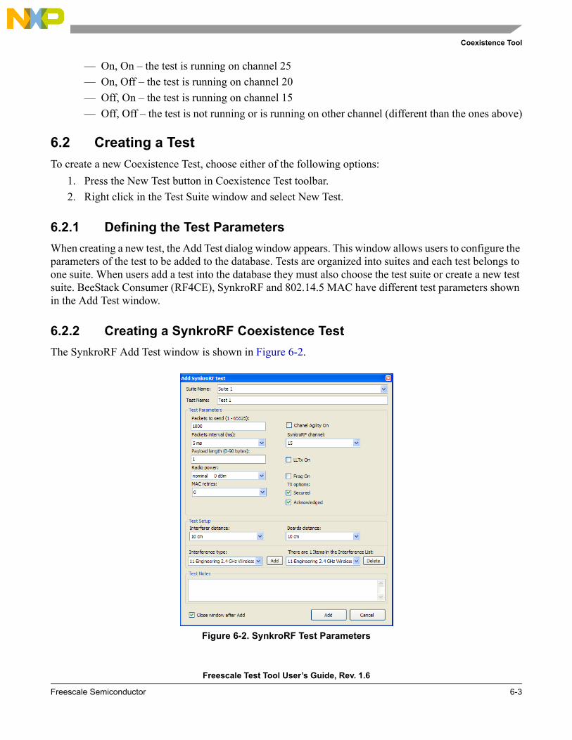
Coexistence Tool
Freescale Test Tool User’s Guide, Rev. 1.6
Freescale Semiconductor 6-3
— On, On – the test is running on channel 25— On, Off – the test is running on channel 20— Off, On – the test is running on channel 15— Off, Off – the test is not running or is running on other channel (different than the ones above)
6.2 Creating a Test To create a new Coexistence Test, choose either of the following options:
1. Press the New Test button in Coexistence Test toolbar.2. Right click in the Test Suite window and select New Test.
6.2.1 Defining the Test Parameters When creating a new test, the Add Test dialog window appears. This window allows users to configure the parameters of the test to be added to the database. Tests are organized into suites and each test belongs to one suite. When users add a test into the database they must also choose the test suite or create a new test suite. BeeStack Consumer (RF4CE), SynkroRF and 802.14.5 MAC have different test parameters shown in the Add Test window.
6.2.2 Creating a SynkroRF Coexistence TestThe SynkroRF Add Test window is shown in Figure 6-2.
Figure 6-2. SynkroRF Test Parameters
Coexistence Tool
Freescale Test Tool User’s Guide, Rev. 1.6
6-4 Freescale Semiconductor
The following SynkroRF test parameters can be configured:Packets to send Number of packets that will be sent from the transmitter node to the receiver node.Packets Interval Time interval between the end of a packet transmission and the start of the next
one.Payload Length Number of bytes in the payload of transmitted packets.Radio Power Transmission power of the transmitter device.MAC Retries Specifies the maximum number of retries performed by the MAC layer for a
packet sent with ACK which has not been acknowledged.Channel Agility On Specifies if the CA mechanism of SynkroRF is enabled. When disabled, the user
should choose one of the 16 IEEE 802.15.4 radio channels from the SynkroRF channel list as the default SynkroRF channel. When CA is enabled, SynkroRF will use channels 15, 20 and 25.
LLTx On Specifies if the Low Latency mechanism for avoiding interferences is enabled. If LLTx is disabled, fragmentation will not be available.
Frag On Specifies if the Fragmentation mechanism for avoiding interferences is enabled.
The Transmit Options are defined as follows:Secured Whether to use secured transmissionAcknowledged Whether to use acknowledged transmissionInterferer distance Distance between the transmitter board and the source of interference
Boards distance Distance between the two boards, transmitter and receiverInterference type Source of interferences. The list displays a limited number of interference sources.
Users can add one or more interference sources to the interference listTest Notes Allows users to enter a short description for the test
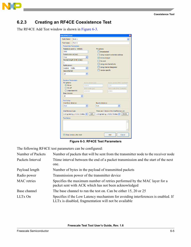
Coexistence Tool
Freescale Test Tool User’s Guide, Rev. 1.6
Freescale Semiconductor 6-5
6.2.3 Creating an RF4CE Coexistence TestThe RF4CE Add Test window is shown in Figure 6-3.
Figure 6-3. RF4CE Test Parameters
The following RF4CE test parameters can be configured:Number of Packets Number of packets that will be sent from the transmitter node to the receiver nodePackets Interval Ttime interval between the end of a packet transmission and the start of the next
one.Payload length Number of bytes in the payload of transmitted packetsRadio power Transmission power of the transmitter deviceMAC retries Specifies the maximum number of retries performed by the MAC layer for a
packet sent with ACK which has not been acknowledgedBase channel The base channel to run the test on. Can be either 15, 20 or 25 LLTx On Specifies if the Low Latency mechanism for avoiding interferences is enabled. If
LLTx is disabled, fragmentation will not be available
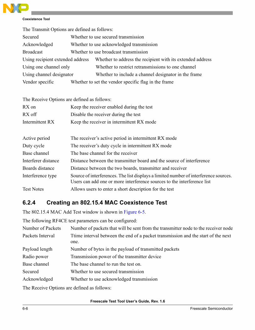
Coexistence Tool
Freescale Test Tool User’s Guide, Rev. 1.6
6-6 Freescale Semiconductor
The Transmit Options are defined as follows:Secured Whether to use secured transmissionAcknowledged Whether to use acknowledged transmissionBroadcast Whether to use broadcast transmissionUsing recipient extended address Whether to address the recipient with its extended addressUsing one channel only Whether to restrict retransmissions to one channelUsing channel designator Whether to include a channel designator in the frameVendor specific Whether to set the vendor specific flag in the frame
The Receive Options are defined as follows:RX on Keep the receiver enabled during the testRX off Disable the receiver during the testIntermittent RX Keep the receiver in intermittent RX mode
Active period The receiver’s active period in intermittent RX modeDuty cycle The receiver’s duty cycle in intermittent RX modeBase channel The base channel for the receiver Interferer distance Distance between the transmitter board and the source of interferenceBoards distance Distance between the two boards, transmitter and receiverInterference type Source of interferences. The list displays a limited number of interference sources.
Users can add one or more interference sources to the interference listTest Notes Allows users to enter a short description for the test
6.2.4 Creating an 802.15.4 MAC Coexistence TestThe 802.15.4 MAC Add Test window is shown in Figure 6-5.
The following RF4CE test parameters can be configured:Number of Packets Number of packets that will be sent from the transmitter node to the receiver nodePackets Interval Ttime interval between the end of a packet transmission and the start of the next
one.Payload length Number of bytes in the payload of transmitted packetsRadio power Transmission power of the transmitter deviceBase channel The base channel to run the test on.Secured Whether to use secured transmissionAcknowledged Whether to use acknowledged transmission
The Receive Options are defined as follows:
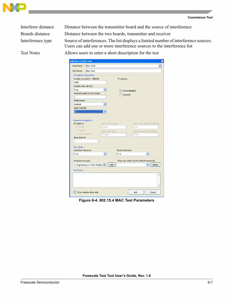
Coexistence Tool
Freescale Test Tool User’s Guide, Rev. 1.6
Freescale Semiconductor 6-7
Interferer distance Distance between the transmitter board and the source of interferenceBoards distance Distance between the two boards, transmitter and receiverInterference type Source of interferences. The list displays a limited number of interference sources.
Users can add one or more interference sources to the interference listTest Notes Allows users to enter a short description for the test
Figure 6-4. 802.15.4 MAC Test Parameters
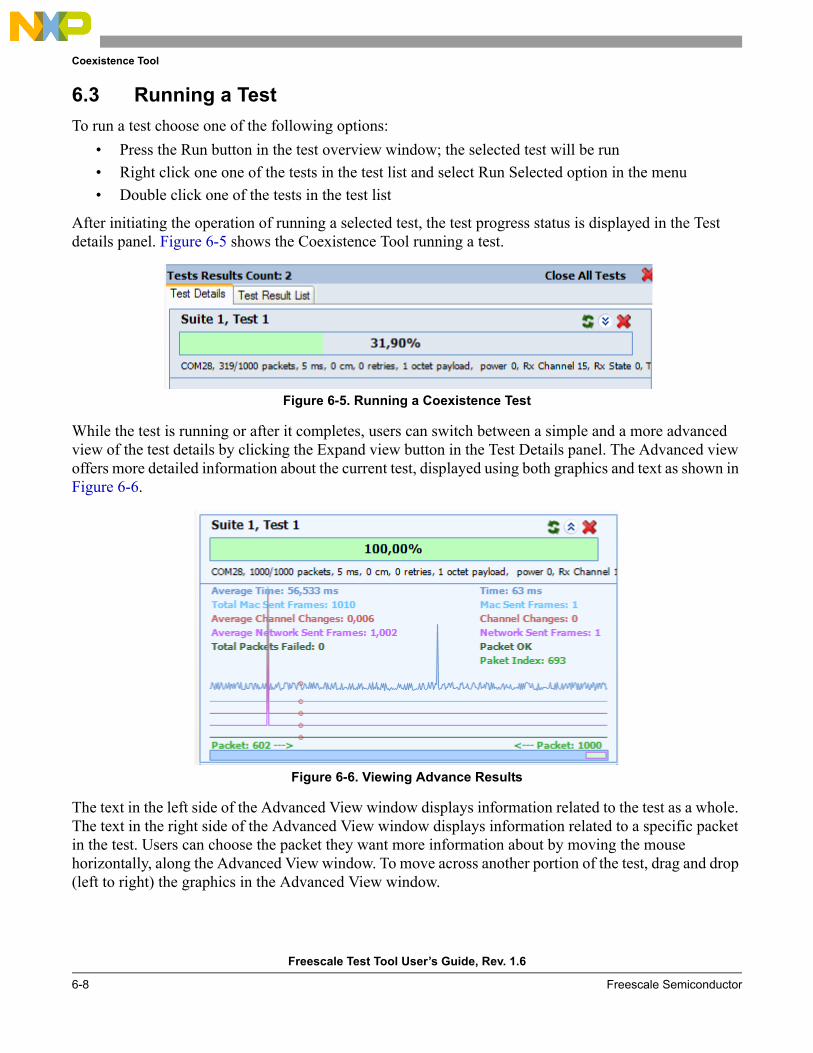
Coexistence Tool
Freescale Test Tool User’s Guide, Rev. 1.6
6-8 Freescale Semiconductor
6.3 Running a TestTo run a test choose one of the following options:
• Press the Run button in the test overview window; the selected test will be run• Right click one one of the tests in the test list and select Run Selected option in the menu • Double click one of the tests in the test list
After initiating the operation of running a selected test, the test progress status is displayed in the Test details panel. Figure 6-5 shows the Coexistence Tool running a test.
Figure 6-5. Running a Coexistence Test
While the test is running or after it completes, users can switch between a simple and a more advanced view of the test details by clicking the Expand view button in the Test Details panel. The Advanced view offers more detailed information about the current test, displayed using both graphics and text as shown in Figure 6-6.
Figure 6-6. Viewing Advance Results
The text in the left side of the Advanced View window displays information related to the test as a whole. The text in the right side of the Advanced View window displays information related to a specific packet in the test. Users can choose the packet they want more information about by moving the mouse horizontally, along the Advanced View window. To move across another portion of the test, drag and drop (left to right) the graphics in the Advanced View window.

Coexistence Tool
Freescale Test Tool User’s Guide, Rev. 1.6
Freescale Semiconductor 6-9
6.4 Viewing Test ResultsAfter running a test, the test results are displayed in the Test Result List panel. Users can choose to run the same test multiple times. All the results of the runs are listed in the Test Result List panel as shown in Figure 6-7.
Figure 6-7. Viewing Test Results
The values displayed in the test result list have the following meaning:Successful Tx Count Number of packets successfully sent.Success Tx Rate Percentage of successfully sent packets from total number of packets indicated to
be sent.Packet Error Rate Percentage of transmitter packet errors (computed as 1 - Success Tx Rate).Received Packets Number of packets successfully received as reported by the receiver.Mean Packet TX Time (msec) Mean duration of each packet transmission.Standard Deviation of Packet Tx Time Statistical deviation for packet transmission duration.

Coexistence Tool
Freescale Test Tool User’s Guide, Rev. 1.6
6-10 Freescale Semiconductor

Freescale Test Tool User’s Guide, Rev. 1.6
Freescale Semiconductor 7-1
Chapter 7 Radio TestThe Radio Test application exercises the lower level Platform and Radio commands on a single node or between two nodes. The Radio Test application accomplishes the following:
1. Test the radio2. Sets up various related parameters (e.g. crystal trim)3. Performs Packet Error Rate (PER) estimation
NOTEThe PER value must be less than 1% to comply with the 802.15.4 Standard. This should be achieved by using packets with a PSDU payload of 20 bytes. The PER test along with the ZTC MAC application, uses MAC frames with a combined header and footer length of 11 bytes. To achieve a 20 byte PSDU payload, create an MSDU of 9 bytes should to validate minimum specification compliance.
7.1 Radio Test Hardware and Software ConsiderationsTwo boards are required to perform the PER test and at least one of those boards must be programmed with a ZigBee Test Client (ZTC) application with ASP support enabled. Also, both boards must be connected to the same Test Tool instance. See Chapter 4, “Firmware Loaders”, for information on how to program the boards.
Freescale recommends that both boards employ the same type of transceiver, that is, both boards should be either HCS08 or MC1322x ARM7 based. However, because the PER test uses MAC commands (which are architecture independent), a board pairing based on different architectures is possible.
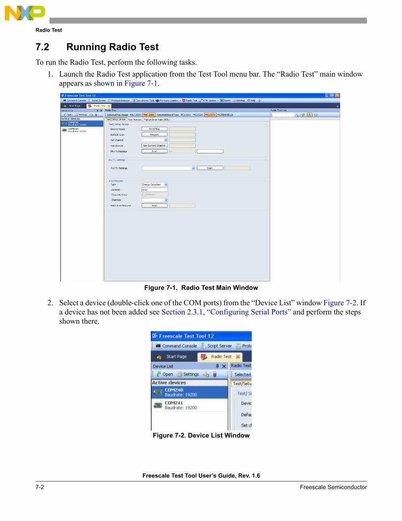
Radio Test
Freescale Test Tool User’s Guide, Rev. 1.6
7-2 Freescale Semiconductor
7.2 Running Radio TestTo run the Radio Test, perform the following tasks.
1. Launch the Radio Test application from the Test Tool menu bar. The “Radio Test” main window appears as shown in Figure 7-1.
Figure 7-1. Radio Test Main Window
2. Select a device (double-click one of the COM ports) from the “Device List” window Figure 7-2. If a device has not been added see Section 2.3.1, “Configuring Serial Ports” and perform the steps shown there.
Figure 7-2. Device List Window
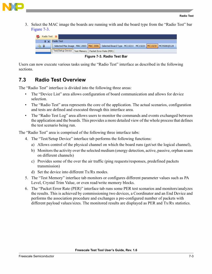
Radio Test
Freescale Test Tool User’s Guide, Rev. 1.6
Freescale Semiconductor 7-3
3. Select the MAC image the boards are running with and the board type from the “Radio Test” bar Figure 7-3.
Figure 7-3. Radio Test Bar
Users can now execute various tasks using the “Radio Test” interface as described in the following sections.
7.3 Radio Test OverviewThe “Radio Test” interface is divided into the following three areas:
• The “Device List” area allows configuration of board communication and allows for device selection.
• The “Radio Test” area represents the core of the application. The actual scenarios, configuration and tests are defined and executed through this interface area.
• The “Radio Test Log” area allows users to monitor the commands and events exchanged between the application and the boards. This provides a more detailed view of the whole process that defines the test scenario being run.
The “Radio Test” area is comprised of the following three interface tabs:4. The “Test/Setup Device” interface tab performs the following functions:
a) Allows control of the physical channel on which the board runs (get/set the logical channel), b) Monitors the activity over the selected medium (energy detection, active, passive, orphan scans
on different channels)c) Provides some of the over the air traffic (ping requests/responses, predefined packets
transmission)d) Set the device into different Tx/Rx modes.
5. The “Test Memory” interface tab monitors or configures different parameter values such as PA Level, Crystal Trim Value, or even read/write memory blocks.
6. The “Packet Error Rate (PER)” interface tab runs some PER test scenarios and monitors/analyzes the results. This is achieved by commissioning two devices, a Coordinator and an End Device and performs the association procedure and exchanges a pre-configured number of packets with different payload values/sizes. The monitored results are displayed as PER and Tx/Rx statistics.
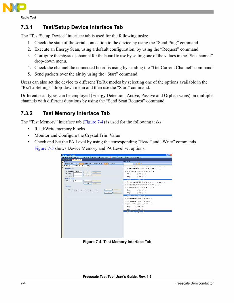
Radio Test
Freescale Test Tool User’s Guide, Rev. 1.6
7-4 Freescale Semiconductor
7.3.1 Test/Setup Device Interface TabThe “Test/Setup Device” interface tab is used for the following tasks:
1. Check the state of the serial connection to the device by using the “Send Ping” command.2. Execute an Energy Scan, using a default configuration, by using the “Request” command.3. Configure the physical channel for the board to use by setting one of the values in the “Set channel”
drop-down menu.4. Check the channel the connected board is using by sending the “Get Current Channel” command5. Send packets over the air by using the “Start” command.
Users can also set the device to different Tx/Rx modes by selecting one of the options available in the “Rx/Tx Settings” drop-down menu and then use the “Start” command.
Different scan types can be employed (Energy Detection, Active, Passive and Orphan scans) on multiple channels with different durations by using the “Send Scan Request” command.
7.3.2 Test Memory Interface TabThe “Test Memory” interface tab (Figure 7-4) is used for the following tasks:
• Read/Write memory blocks• Monitor and Configure the Crystal Trim Value• Check and Set the PA Level by using the corresponding “Read” and “Write” commands
Figure 7-5 shows Device Memory and PA Level set options.
Figure 7-4. Test Memory Interface Tab
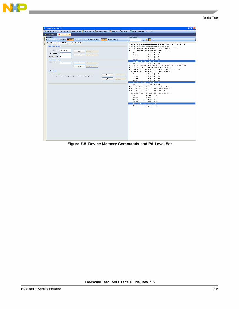
Radio Test
Freescale Test Tool User’s Guide, Rev. 1.6
Freescale Semiconductor 7-5
Figure 7-5. Device Memory Commands and PA Level Set
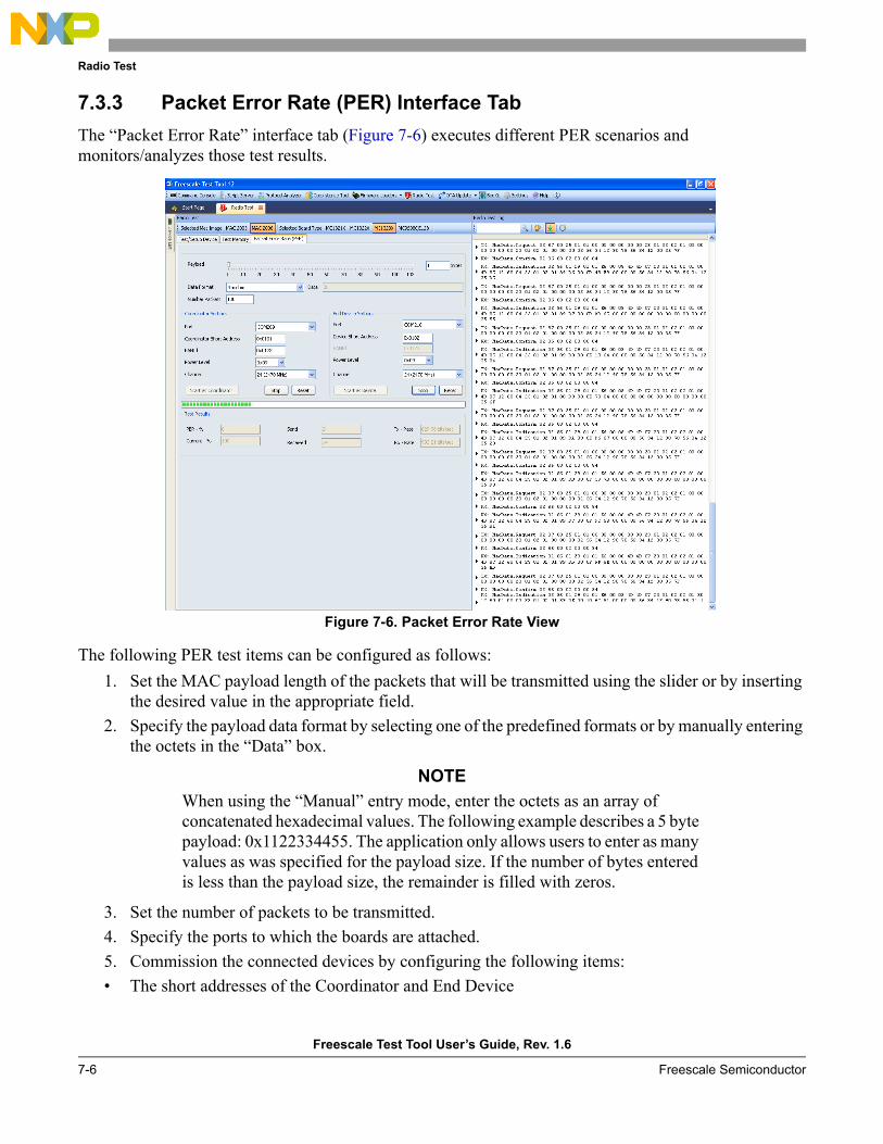
Radio Test
Freescale Test Tool User’s Guide, Rev. 1.6
7-6 Freescale Semiconductor
7.3.3 Packet Error Rate (PER) Interface TabThe “Packet Error Rate” interface tab (Figure 7-6) executes different PER scenarios and monitors/analyzes those test results.
Figure 7-6. Packet Error Rate View
The following PER test items can be configured as follows:1. Set the MAC payload length of the packets that will be transmitted using the slider or by inserting
the desired value in the appropriate field.2. Specify the payload data format by selecting one of the predefined formats or by manually entering
the octets in the “Data” box.
NOTEWhen using the “Manual” entry mode, enter the octets as an array of concatenated hexadecimal values. The following example describes a 5 byte payload: 0x1122334455. The application only allows users to enter as many values as was specified for the payload size. If the number of bytes entered is less than the payload size, the remainder is filled with zeros.
3. Set the number of packets to be transmitted.4. Specify the ports to which the boards are attached.5. Commission the connected devices by configuring the following items:• The short addresses of the Coordinator and End Device
Radio Test
Freescale Test Tool User’s Guide, Rev. 1.6
Freescale Semiconductor 7-7
• The PAN ID of the network to be created• The PWR Level of the devices• The Channel to be used by the devices to communicate6. Press the “Start as Coordinator” button to initialize the first board as Coordinator and start the
network.7. Press the “Start as Device” button to initialize the second board as an End Device and associate it
to the already started Coordinator.
After these steps are executed, the data transmission between the test devices will start. Devices can be reset or stopped by using the appropriate buttons. During PER test execution, the following statistics can be monitored:
• PER - %• Current - %• Sent• Received• Tx – Rate• Rx – Rate

Radio Test
Freescale Test Tool User’s Guide, Rev. 1.6
7-8 Freescale Semiconductor