Embed Size (px)
Citation preview
User Guide
FreeSpeak II User Guide
Part Number: 399G169 Rev D
Date: June 15, 2018

User Guide| FreeSpeak II Base
Document referenceFreeSpeak II Base User Guide
399G169 Rev D
Legal disclaimers
Copyright © 2018 HME Clear-Com LtdHME Clear-Com Ltd
All rights reserved
Clear-Com, the Clear-Com logo, and Clear-Com Concert are trademarks or registeredtrademarks of HM Electronics, Inc.
The software described in this document is furnished under a license agreement and may be usedonly in accordance with the terms of the agreement.
The product described in this document is distributed under licenses restricting its use, copying,distribution, and decompilation / reverse engineering. No part of this document may bereproduced in any form by any means without prior written authorization of Clear-Com, an HMECompany.
Clear-Com Offices are located in California, USA; Cambridge, UK; Dubai, UAE; Montreal,Canada; and Beijing, China. Specific addresses and contact information can be found on Clear-Com’s corporate website: www.clearcom.com
Clear-Com contacts:
Americas and Asia-Pacific Headquarters
California, United States
Tel: +1 510 337 6600
Email: [email protected]
Europe, Middle East, and Africa Headquarters
Cambridge, United Kingdom
Tel: +44 1223 815000
Email: [email protected]
China Office
Beijing Representative Office
Beijing, P.R. China
Tel: +8610 65811360/65815577
Page 2
User Guide| FreeSpeak II Base
Table of contents
1 What is FreeSpeak II? 1
1.1 FreeSpeak II Base 1.9 GHz/2.4 GHz 1
1.2 2-wire, 4-wire and wireless intercom 1
1.3 Flexible configuration 2
1.4 Live set-up and control 2
1.5 System capacity 3
2 Using the Base Station 5
2.1 About the Base Station 5
2.2 Base Station controls 5
2.3 What is a Keyset? 6
2.4 Key behavior 8
2.5 FreeSpeak II Base rear connectors 10
2.6 Pinouts 11
2.7 Powering your system 13
2.8 Networking/IP Issues 15
2.9 Using the Event Log 17
2.10 FreeSpeak II Base Station menu 'at-a-glance' guide 18
2.11 Save system settings 20
3 Using the transceivers 23
3.1 Transceiver capacity (how many beltpacks?) 24
3.2 IP rating (international protection marking) 24
3.3 Transceiver connectors 24
3.4 FreeSpeak II Base 1.9 GHz/2.4 GHz 25
3.5 Transceiver placement 25
3.6 Install transceivers 30
3.7 Site survey 30
3.8 Interpreting the Site Survey screen 31
3.9 How to put a beltpack into Site Survey mode 32
3.10 Standalone site survey 32
3.11 Radio frequency (RF) issues 34
3.12 Using a transceiver with a fiber connection 35
3.13 Transceiver sync compensation (cable compensation) 36
4 Using the FreeSpeak II Basesplitter (FSII-SPL) 39
4.1 Configuration using a splitter with Cat 5/6 RJ45 connection 39
Page 3

User Guide| FreeSpeak II Base
4.2 Configuration using a splitter with fiber connection 40
4.3 Splitter (FSII-SPL) rear connectors 41
4.4 Splitter (FSII-SPL) front panel 42
4.5 Using a transceiver with a fiber connection 42
4.6 Splitter software version (FSII-SPL) 44
5 Registering beltpacks 46
5.1 Registering beltpacks 47
5.2 Registering beltpacks using USB cable 47
5.3 Register beltpacks over-the-air (OTA) 49
5.4 Unregister beltpacks 52
6 Using beltpacks 55
6.1 Beltpack settings 56
6.2 Volume Operation 60
6.3 Menu Key Operation 62
6.4 Master volume low level limiter (beltpacks) 64
6.5 Set the audio RF filter 65
6.6 Configurable eavesdropping 66
6.7 AA Battery Type: Alkaline /NiMh 67
6.8 Accessing beltpack Admin menu 68
7 Using Roles 70
7.1 About FreeSpeak II Base II Roles 70
7.2 Default Role settings 70
7.3 Changing Channels on beltpacks 71
7.4 Change beltpack settings 75
7.5 How to create Roles for beltpacks 75
7.6 Save Settings 76
7.7 Fixed Roles 79
8 Accessing the Core Configuration Manager (CCM) 83
8.1 Core Configuration Manager (CCM) Walk-through 83
9 Configuring audio routes in FreeSpeak II Base 89
9.1 Channels 89
9.2 Groups 89
9.3 Channel or Group? 90
9.4 Group 92
9.5 Example Group set-up 93
Page 4

User Guide| FreeSpeak II Base
9.6 Example audio assignment 95
9.7 Assign Channels to beltpack keys (A, B, C, D, Reply) 97
9.8 Change Channel settings on the Base Station 101
9.9 Configure a one-to-one connection 104
9.10 Example point-to-point audio assignment 104
10 Interconnecting intercom systems 105
10.1 How do I connect to other intercom devices? 105
10.2 Connecting 2-wire equipment 105
10.3 Connecting to 4-wire equipment 105
10.4 Port Function 106
11 Using General Purpose inputs and outputs (GPIOs) 108
11.1 How to configure a GPI when using FSII Base II 108
11.2 How to configure a GPO when using FSII Base II 113
11.3 Test GPIOs 115
11.4 Control Events 116
12 Upgrading your devices 119
12.1 How to upgrade your devices 119
13 Specifications 122
13.1 Base Station 122
13.2 FreeSpeak II Beltpack 123
13.3 FreeSpeak II Transceiver 124
13.4 FreeSpeak II Splitter 125
13.5 Transmission Method 125
13.6 Notice about Specifications 126
14 Regulatory compliance 127
14.1 FCC Notice 127
14.2 FCC/IC/EC RF Exposure Warning 127
14.3 Industry Canada Compliance Statement 128
14.4 Korean Notice 128
14.5 KCC 2.4Ghz warning 128
14.6 European Union (CE mark) 128
14.7 Waste Electrical and Electronic Equipment (WEEE) 129
Page 5

User Guide| FreeSpeak II Base
Important Safety Instructionsl Intended Audience: Professional, Technical and Qualified Personnel
l Read these instructions.
l Keep these instructions.
l Heed all warnings.
l Follow all instructions.
l Do not use this apparatus near water.
l Clean only with dry cloth.
l Install in accordance with the manufacturer’s instructions.
l Do not install near any heat sources such as radiators, heat registers, stoves, or otherapparatus (including amplifiers) that produce heat.
l Do not defeat the safety purpose of the polarized or grounding-type plug. A polarized plughas two blades and a third grounding prong. The wide blade or the third prong is providedfor your safety. If the provided plug does not fit into your outlet, consult an electrician forreplacement of the obsolete outlet.
l Protect the power cord from being walked on or pinched particularly at plugs, conveniencereceptacles, and the point where they exit from the apparatus.
l Only use attachments/accessories specified by the manufacturer.
l Unplug this apparatus during lightning storms or when unused for long periods of time.
l Refer all servicing to qualified service personnel. Servicing is required when the apparatushas been damaged in any way such as; power-cord supply or plug is damaged, liquid hasbeen spilled, objects have fallen into the apparatus, the apparatus has been exposed toheavy rain, the apparatus does not operate normally.
l Caution: Shielded Cable Requirement
l Shielded Cable is required for ALL LQ SERIES GPIO Port connectivity. Shielded Cablemust be used to assure compliance with domestic and international emissions standards.Customers, Installers and or qualified Personnel failing to use shielded cables may causeradio interference in which case the user may be required to take adequate measures.
Page 6

User Guide| FreeSpeak II Base
1 What is FreeSpeak II?The FreeSpeak II wireless intercom system includes wired and wireless beltpacks thatcommunicate using a cellular network of transceivers (1.9 and 2.4 GHz).
1.1 FreeSpeak II Base 1.9 GHz/2.4 GHz
1.2 2-wire, 4-wire and wireless intercom
These different devices communicate seamlessly.
Page 1

User Guide| FreeSpeak II Base
1.3 Flexible configuration
Pre-configured beltpack Roles allow both rapid set-up and flexible configuration.
l Use simple default set-up; all beltpacks on Channel 1 and 2
l or, customize the set-up to suit your needs.
l System has either 25 (FSII-BASE-II) or 5 (FSII-BASE-II-5) beltpack Roles. FSII-BASE-II-5 offers a license to upgrade to 25 beltpacks if required.
See Using Roles on page 70.
1.4 Live set-up and control
Use the front panels of the Base Station, or the browser-based Core Configuration Manager(CCM).
Press Menu button on the Base Station to access controls:
FreeSpeak II Base Station menu 'at-a-glance' guide on page 18
The browser-based Core Configuration Manager (CCM) is accessed via device IP address.
Page 2

User Guide| FreeSpeak II Base
For more information, seeAccessing the Core Configuration Manager (CCM) on page 83
1.5 System capacity
l Up to 25 wireless beltpacks,10 transceivers per base
l FSII-BASE-II: 25 beltpack capacity
l FSII-BASE-II-5: 5 beltpack capacity. To upgrade to 25 beltpacks you need to obtain alicence from your Clear-Com dealer.
l 12 Partyline Channels
l 12 Group set-ups
Page 3

User Guide| FreeSpeak II Base
l Beltpack to beltpack connection (point-to-point)
l Completely scalable and configurable
l Unrivalled audio quality
l Up to four GPO and two GPI controls
Page 4

User Guide| FreeSpeak II Base
2 Using the Base Station
2.1 About the Base Station
The FreeSpeak II Base Station routes communication to and from wireless beltpacks. Itprovides a control point for audio and allows the user to configure the system, either from thefront panel menus or using the online configuration manager.
l Press Menu button to configure your audio set up from the Base.
See Accessing the Core Configuration Manager (CCM) on page 83 for details about onlineconfiguration.
2.2 Base Station controls
Label Connector function
AUSB port. Use when registering beltpacks to the Base Station. Also use whenupgrading device or saving/restoring system settings. See Registering beltpackson page 47, Save system settings on page 20 or Upgrading your devices onpage 119.
B Base headset connector (4-pin XLR female).
C Menu button. Push to enter menu mode and control system settings. Push againto exit menu mode, or leave to time-out.
Page 5

User Guide| FreeSpeak II Base
Label Connector function
D Mode button. Use to view transceiver performance in base menu screens. Togglebetween diagnostic view and normal keyset view.
E Push to toggle headset microphone on and off.
Keyset
A Keyset is a set of controls associated with an audio assignment. On the Base, aKeyset is made up of a viewing screen and three controls (a rotary and two pushbuttons). The viewing screen shows a Channel and any associated messages.The rotary controls volume to that Channel, and the push buttons control Call andTalk to the Channel. The viewing screens are also used to display menu and modeinformation.
F Stage Announce. Allows the Base operator to talk on the Stage Announce output.Push and hold to talk.
G All Talk. Allows the Base operator to talk to all wired and wireless beltpacks (2-Wire and 4-Wire). Push and hold to talk.
H Remote Mic Kill (RMK). Allows Base operator to remotely unlatch all beltpack talkkeys, wireless and wired.
IStatus LED 1 = Transceiver warning light. If green, all transceivers are online.Status LED 2 = Beltpack warning light. If green all BPs have sufficient batterypower. If either light is amber (or red), you can press the mode button to check theissue in the diagnostics screens.
JControls overall volume to the Base headset. This includes Channels, programfeed and any other available audio. Turn rotary to adjust volume, push to turnheadset sound on and off.
K Program feed to Base headset volume and control. Turn rotary to adjust volume,push to turn feed on and off. (Does not affect program feed in Channels).
2.3 What is a Keyset?
A Keyset is a set of controls associated with an audio assignment. The default configuration of theBase Station has three Partyline audio assignments, and a Reply assignment. Beltpacks have twoPartyline audio assignments, two call assignments, and one reply assignment by default.
2.3.1 Main Station KeysetsThe Keysets on a Base Station is made up of 4 viewing screens, each with an associated rotarycontroller, a Call key and a Talk key. These controls display and regulate the audio routes
Page 6

User Guide| FreeSpeak II Base
associated with the Base. As well as controlling audio assignments, the viewing screens displaymenu options and wireless diagnostics.
2.3.2 Beltpack KeysetsThe Keyset on a beltpack has one screen and two sets of controls, to the left and right of thescreen. The main assignments are on keys A & B and subsidiary assignments are on C & D.Additionally, the Reply key can be over-ridden with an audio assignment. The default set-up for abeltpack puts Channel 1 on keys A and C, and Channel 2 on keys B and D.
Page 7

User Guide| FreeSpeak II Base
2.4 Key behavior
Keys can be set to different talk and listen states.
Key behavior options Resulting audio behavior
Talk-only Press key to talk. Key only controls talk.
Listen-only Press key to listen. Key only controls listen.
Talk and Listen Press key to talk and listen.
Dual Talk and ListenPress key to talk and listen. Listen latches on or offaccording to preference (quick tap to latch). Usercontrols listen state.
Force Listen Permanent listen.
Talk and Force Listen Permanent listen, push key to talk.
Force Talk and Force Listen Permanent listen and talk.
Page 8

User Guide| FreeSpeak II Base
2.4.1 Set key behaviorKey behavior can be set from the CCM or the Base Station.
Page 9
User Guide| FreeSpeak II Base
Note: Key behavior is modified by key latch state. When key is set to latch, latch is activated by a quicktap on the key.
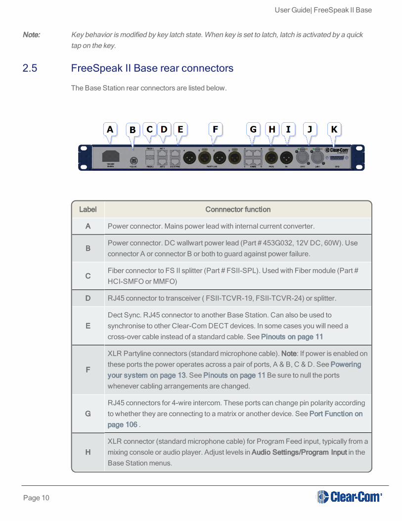
2.5 FreeSpeak II Base rear connectors
The Base Station rear connectors are listed below.
Label Connnector function
A Power connector. Mains power lead with internal current converter.
BPower connector. DC wallwart power lead (Part # 453G032, 12V DC, 60W). Useconnector A or connector B or both to guard against power failure.
CFiber connector to FS II splitter (Part # FSII-SPL). Used with Fiber module (Part #HCI-SMFO or MMFO)
D RJ45 connector to transceiver ( FSII-TCVR-19, FSII-TCVR-24) or splitter.
EDect Sync. RJ45 connector to another Base Station. Can also be used tosynchronise to other Clear-Com DECT devices. In some cases you will need across-over cable instead of a standard cable. See Pinouts on page 11
F
XLR Partyline connectors (standard microphone cable). Note: If power is enabled onthese ports the power operates across a pair of ports, A & B, C & D. See Poweringyour system on page 13. See Pinouts on page 11 Be sure to null the portswhenever cabling arrangements are changed.
GRJ45 connectors for 4-wire intercom. These ports can change pin polarity accordingto whether they are connecting to a matrix or another device. See Port Function onpage 106 .
HXLR connector (standard microphone cable) for Program Feed input, typically from amixing console or audio player. Adjust levels in Audio Settings/Program Input in theBase Station menus.
Page 10

User Guide| FreeSpeak II Base
Label Connnector function
I XLR connector (standard microphone cable) for Stage Announce output.
J2 x RJ45 ports. These can be used for network connection or for daisy-chainingdevices. Note: The ports share an IP address, so only one network connection ispossible (either port can be used).
K GPIO connector. See Pinouts on page 11.
Note: For connection between the Base and transceiver/splitter and digital audio feeds, Clear-Comrecommends shielded Cat 5/6 cable of no less than 24 AWG. Use of other cable can result inshorter cable runs and other performance problems.
2.6 Pinouts
2.6.1 DECT SYNC (connector E)
Sync In Sync Out
Pin 1 DECTSYNC + DECTSYNC +
Pin 2 DECTSYNC - DECTSYNC -
Pin 3 8 KHZ+ 8 KHZ+
Pin 6 8 KHZ- 8 KHZ-
2.6.2 Partyline (connectors F)
Pin Description
Pin 1 Ground (shield)
Pin 2 Power
Pin 3 Audio
Page 11

User Guide| FreeSpeak II Base
2.6.3 4-wire intercom (connectors G)See Port Function on page 106
2.6.4 GPIO/DB15 connector (K)
Pin Description
Pin 1 Relay 1 COM
Pin 2 Relay 1 NC
Pin 3 Relay 1 NO
Pin 4 Relay 2 COM
Page 12

User Guide| FreeSpeak II Base
Pin Description
Pin 5 Relay 2 NC
Pin 6 Relay 2 NO
Pin 7 Input 1 (Ground to activate)
Pin 8 GND
Pin 9 Relay 3 COM
Pin 10 Relay 3 NC
Pin 11 Relay 3 NO
Pin 12 Relay 4 COM
Pin 13 RELAY 4 NC
Pin 14 RELAY 4 NO
Pin 15 Input 2 (Ground to activate)
2.7 Powering your system
The powering requirements for your FreeSpeak II devices are detailed below.
2.7.1 Powering the FreeSpeak II BaseThere are two power supplies, used according to preference:
l Mains power lead ( internal power converter)
l DC connector. External AC/DC DIN4 power adapter.
Use one power connector or both to guard against one failing.
2.7.2 Powering wireless beltpacksBeltpacks are usually powered by Li-ion battery. A drop-in battery charger is supplied.
Battery power status is viewed from:
l Base Station menu screens
l Beltpack menu screens
l Core Configuration Manager (CCM).
For more information see:
Page 13

User Guide| FreeSpeak II Base
Battery Charger Quick Start Guide (PDF available from HME Clear-Com Ltd website).
Note: You can also power beltpacks using standard AA batteries for convenience. In situations where Li-ion batteries are prohibited, you can also use nickel metal hydride batteries (NiMN) but will need toset battery type so battery life diagnostics are accurate. See AA Battery Type: Alkaline /NiMh onpage 67.
2.7.3 Power 2-wire beltpacks from the Partyline2-wire Partyline beltpacks can take power from the Partyline:
l FreeSpeak base power : 60 watts supply = 250 mA to Partyline
l Approximately10 beltpacks per pair of ports (depending on your set up), max 20 beltpacksper base.
To enable power to the Partyline go to Ports, 2-wire in the CCM or in Base front menu screens.
2.7.4 Powering the transceiversl Directly (DC in power connector) or
l From the FreeSpeak II Base or splitter
Direct power to transceiver is recommended. Direct power will increase how far transceiverscan be positioned from the Base
Transceiver powered locally:
l Shielded Cat 5/6 24 AWG cable up to 800 m (2,625 feet) from base or splitter.
l Shielded Cat 5/6 26 AWG cable up to 400 m (1,312 feet) from base or splitter.
Transceiver powered from Base Station (1 transceiver only):
l Shielded Cat 5/6 24 AWG cable, up to 100 m ( 328 feet) from base or splitter.
l Shielded Cat 5/6 26 AWG cable, up to 50 m (164 feet) from base or splitter.
Note: Using heavier gauge cable will increase available distance. Clear-Com recommends using 24AWG cable.
For more information see:
l Using the transceivers on page 23
l Site survey on page 30
2.7.5 Powering the Transceiver SplitterThe splitter MUST be powered locally.
Page 14

User Guide| FreeSpeak II Base
2.7.6 Recommended powering and cable lengths for a SystemThe Base Station can power 1 transceiver. More than one transceiver requires direct powersupplied to the transceiver.
The figures in this table are based on the use of 24AWG Cat5/6 cable
Capacity (distance and no. ofdevices)
Base to transceiver. No PSU at transceiver.1 transceiver only. 100 meters (328feet).
Base to transceiver. PSU at transceivers.2 transceivers. 800 meters (2625feet).
Base to splitter. Splitter must have PSU. 800 meters (2625 feet).
Splitter to transceiver. Transceivers powered by splitter,no PSU at transceiver.
5 transceivers per splitter. 100meters (328 feet).
Splitter to transceiver. PSU supplied to transceivers.5 transceivers per splitter. 800meters (2625 feet).
The figures in this table are based on the use of 26AWG Cat5/6 cable
Capacity (distance and no. ofdevices)
Base to transceiver. No PSU at transceiver.1 transceiver only. 50 meters (164feet).
Base to transceiver. PSU at transceivers.2 transceivers. 400 meters (1312feet).
Base to splitter. Splitter must have PSU. 400 meters (1312 feet).
Splitter to transceiver. Transceivers powered by splitter,no PSU at transceiver.
5 transceivers per splitter. 50 meters(164 feet).
Splitter to transceiver. PSU supplied to transceivers.5 transceivers per splitter. 400meters (1312 feet).
Note: Distance between Base and transceivers can be increased by connecting via Fiber.
2.8 Networking/IP Issues
Configure your IP network to work optimally with your FreeSpeak II devices.
Page 15

User Guide| FreeSpeak II Base
2.8.1 Dynamic host configuration protocol (DHCP)The FreeSpeak II Base is set to DHCP by default. For fast set-up, DHCP is the best option to useas the Base Station can be immediately connected to any network which provides DHCP. Mostnetworks allocate IP addresses using DHCP. The addresses provided are dynamic and willchange from time to time.
2.8.2 Static IP configurationIf your intercom installation becomes permanent, obtain a static IP address to avoid the Base IPaddress from changing periodically.
2.8.3 Netmask or subnetThe netmask or subnet divides the network into sectors for more efficient routing and is requiredwhen allocating a static IP address to a Base Station. Your network administrator should providedetails.
2.8.4 GatewayThis setting is optional. It is required if your system navigates across subnets (as might be the casewhen accessing the CCM across networks, or linking systems). If not explicitly stated, Gatewaywill revert to the device IP address.
2.8.5 Set static IP details for Base StationSet static IP address in the CCM.
Set static IP address from the Base Station menu screens.
Page 16

User Guide| FreeSpeak II Base
1. Disable DHCP
2. Enter static IP address
3. Edit subnet and gateway details as required.
Find the IP address in the front menu screens of your device.
Note: If you are having trouble connecting to the CCM for your Base Station, one possibility is an IPclash (two devices attempting to use the same IP address).
2.9 Using the Event Log
The Event Log enables you to examine a list of entries that the Base Station automatically creates.This checks the status of your system, and helps to diagnose and solve any issues.
Page 17

User Guide| FreeSpeak II Base
To access the Event Log, go to Device > Event Log. The Event Log window displays:
2.10 FreeSpeak II Base Station menu 'at-a-glance' guide
List item Description
2.10.1 Audio Settings:l Headset
l Program input
l Stage announce output
2.10.2 Station settings:l Program audio on Base station Keysets (1-4)
l Display settings
l Make Base headset a Group Member (listen to group announcements)
Page 18

User Guide| FreeSpeak II Base
l TCVR Port
2.10.3 Channelsl Change Channel name (label)
2.10.4 Groupsl Change Group name (label)
2.10.5 4-wire audiol Program audio for 4-wire (Ports 1-4)
2.10.6 2-wire audio, A&B, C&D.l Program audio for 2-wire (Ports A&B, C&D)
2.10.7 Key Assignl Select each beltpack (Role) and program/edit audio on keys (A,B,C,D)
2.10.8 Beltpacksl Change beltpack Role
l Unregister beltpacks
l Check beltpack software version
l Fix beltpack Role
2.10.9 Rolesl Create, clone and delete Roles
l Edit Role settings, e.g. change channel, alter volume, set menu access etc.
2.10.10 Transceiversl Change transceiver name (label)
l Set cable compensation if required
2.10.11 Networkingl Station id (name)
l DHCP or Static IP (see Networking/IP Issues on page 15 for more information)
Page 19

User Guide| FreeSpeak II Base
l Base station IP address
2.10.12 Administrationl Beltpacks: start over-the-air registration
l Software: View version and upgrade
l License: View license and upgrade
l Reset to factory settings and reboot
l Save and restore settings
l Change menu access pin code
l Set AA battery type
2.11 Save system settings
You can back up your system to a USB or directory. We advise that you backup your systemconfiguration. Saving settings will save Role, Base Station and transceiver configuration.
Page 20

User Guide| FreeSpeak II Base
How to save settings from the CCM :
How to save settings from the Base Station menus
Page 21

User Guide| FreeSpeak II Base
Page 22
User Guide| FreeSpeak II Base
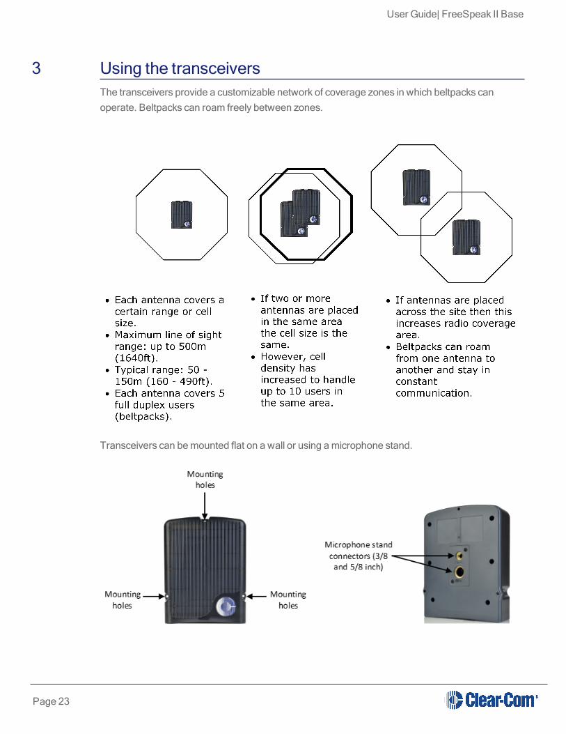
3 Using the transceiversThe transceivers provide a customizable network of coverage zones in which beltpacks canoperate. Beltpacks can roam freely between zones.
Transceivers can be mounted flat on a wall or using a microphone stand.
Page 23

User Guide| FreeSpeak II Base
3.1 Transceiver capacity (how many beltpacks?)
Clear-com recommends a conservative approach to transceiver capacity, to ensure coverage andallow for system losses.
1.9 GHz : 3 - 4 beltpacks per transceiver
2.4 GHz: 2 - 3 beltpacks per transceiver.
3.2 IP rating (international protection marking)
The transceiver has an IP rating of 65 so it can be mouted outside and will be resistant to weatherconditions.
3.3 Transceiver connectors
Page 24

User Guide| FreeSpeak II Base
3.4 FreeSpeak II Base 1.9 GHz/2.4 GHz
The two sets of equipment can be used separately or together.
Which frequency you use affects how many beltpacks can be used in any one radio frequency(RF) cell (the range of one transceiver).
Each transceiver is designed to handle 5 beltpacks in the 1.9 GHz range and 4 beltpacks in the 2.4GHz range, simultaneously and in good conditions. If interference or propagation problems occurin an area it may be practical to install one less beltpack for each transceiver.
For most working systems, Clear-Com uses a ratio of 3 - 4 (1.9 GHz) or 2-3 (2.4 GHz) users pertransceiver. This is due to system losses.
3.5 Transceiver placement
Each FreeSpeak II Base has capacity for 25 beltpacks and up to 10 transceivers (using twosplitters). You need to place transceivers to create a custom coverage zone to suit yourrequirements, taking into account the physical environment and beltpack user needs.
Page 25

User Guide| FreeSpeak II Base
l Example set up.
3.5.1 Things to take into accountl Consider both capacity and coverage. How many beltpack users are there and what are
their movements? Ensure that you have enough capacity where users congregate, as wellas allowing for coverage area.
l What are the individual characteristics of your site? Radio waves can be reflected bymetallic objects, and reduced by some objects, including the human body (for instance, alarge audience can affect transmission).
l What conduit (cabling) is already available on site? Are there power points? Splitters mustbe powered locally, and Clear-Com recommends powering transceivers locally.
l As a general rule, transceivers should be placed 8 – 10 feet high (2.5 – 3 meters high).
Page 26

User Guide| FreeSpeak II Base
l When co-locating transceivers for extra beltpack capacity in one area, do not put thedevices too close to each other. They should be placed between 3 and 20 feet (1 - 7 meters)apart .
l FS II transceivers can be placed at any orientation in confined areas. However, in largervenues or outdoors, aim the transceiver to the front of the required coverage area.
3.5.2 Transceiver capacity (how many beltpacks?)Clear-com recommends a conservative approach to transceiver capacity, to ensure coverage andallow for system losses.
1.9 GHz : 3 - 4 beltpacks per transceiver
2.4 GHz: 2 - 3 beltpacks per transceiver.
3.5.3 Transceiver coverage (how far?)Transceivers provide circular (omnidirectional) coverage.
In ideal conditions, a transceiver range can go up to 500 meters (1640 feet). However, an averagerange, taking into account objects and conditions that impede radio waves, is between 50 - 150meters (164 - 490 feet).
Page 27

User Guide| FreeSpeak II Base
3.5.4 Possible distance from Base Station to transceiverThe Base Station can power 1 transceiver to a distance of 100 meters (328 feet). More than onetransceiver and/or greater distances will need direct power supplied to the transceiver.
The figures in this table are based on the use of 24AWG Cat5/6 cable
Capacity (distance and no. ofdevices)
Base to transceiver. No PSU at transceiver.1 transceiver only. 100 meters (328feet).
Base to transceiver. PSU at transceivers.2 transceivers. 800 meters (2625feet).
Base to splitter. Splitter must have PSU. 800 meters (2625 feet).
Splitter to transceiver. Transceivers powered by splitter,no PSU at transceiver.
5 transceivers per splitter. 100meters (328 feet).
Page 28

User Guide| FreeSpeak II Base
The figures in this table are based on the use of 24AWG Cat5/6 cable
Capacity (distance and no. ofdevices)
Splitter to transceiver. PSU supplied to transceivers.5 transceivers per splitter. 800meters (2625 feet).
The figures in this table are based on the use of 26AWG Cat5/6 cable
Capacity (distance and no. ofdevices)
Base to transceiver. No PSU at transceiver.1 transceiver only. 50 meters (164feet).
Base to transceiver. PSU at transceivers.2 transceivers. 400 meters (1312feet).
Base to splitter. Splitter must have PSU. 400 meters (1312 feet).
Splitter to transceiver. Transceivers powered by splitter,no PSU at transceiver.
5 transceivers per splitter. 50 meters(164 feet).
Splitter to transceiver. PSU supplied to transceivers.5 transceivers per splitter. 400meters (1312 feet).
Note: Connecting devices over Fiber will increase potential distances from Base to transceiver. SeeInstall Fiber Module.
It is advisable to place transceivers temporarily until coverage has been tested. Once transceivershave been temporarily placed, test the coverage zone by putting a beltpack in Site Survey modeand walking through the area monitoring signal strength.
Page 29

User Guide| FreeSpeak II Base
l Conduct a Site survey on page 30.
3.6 Install transceivers
When installing transceivers, please give careful thought to transceiver placement, taking intoaccount the capacity (how many beltpacks) and coverage area that is needed. Also, take note ofradio frequency issues covered in this guide. Refer to the section on transceiver placement in thisguide for more information.
3.7 Site survey
A site survey involves temporary placement of transceivers while testing coverage (area coveredby radio frequency) and capacity (how many beltpacks can be supported) by the system.
After placing the transceiver(s) in a temporary way, a beltpack user walks through all the areaswhere beltpack users will typically be moving, noting any areas of weak signal, dropout, ordisconnection of the system.
For extensive or complicated systems it is helpful to draw a map of the area with transceiverplacement and corresponding RF cells. For a smaller system, just testing one transceiver inStandalone mode may be sufficient.
To test coverage areas, put the beltpack into Site Survey mode. For more information, see:
l How to put a beltpack into Site Survey mode on page 32
l Interpreting the Site Survey screen on page 31
l Standalone site survey on page 32
3.7.1 Transceiver coverage zoneTransceiver coverage zone = area where
l RSSI => 30
l Link Quality => 3
for all beltpacks.
Adjust transceiver placement to get the best coverage. Coverage zones should be overlapped.Example coverage zones are shown below.
Page 30

User Guide| FreeSpeak II Base
3.8 Interpreting the Site Survey screen
The four numbers on this screen represent, from left to right:
l Transceiver
l RSSI (Received Signal Strength Indication)
l FER (Frame Error Rate)
l Link Quality (this figure is a calculation based on RSSI and FER).
Page 31

User Guide| FreeSpeak II Base
Note: You can press the Mode button on the front of the Base Station to check transceiver performanceat any time.
3.9 How to put a beltpack into Site Survey mode
The beltpack must have advanced menu access (set menu access in Roles/Beltpack Role/MenuAccess from Base Station menus or the CCM).
1. Press and hold the menu button on the beltpack for 2 seconds to enter menu mode.
2. Navigate to Site Survey in the Master menu using rotary controllers to scroll through menuoptions. Site survey is at the bottom of the Master menu.
3. Press D key to select Site Survey. Use C key to go back or cancel.
3.10 Standalone site survey
You might need to scope a site (check the range and performance of a transceiver) withoutconnecting to a Base Station. To do this a beltpack and transceiver can be connected inStandalone mode.
Make sure you have to hand:
l A powered beltpack
l A transceiver
l A DC in XLR (male) power connector for the transceiver
l Access to a power socket.
Page 32

User Guide| FreeSpeak II Base
1. Connect power to the transceiver and at the same time press the black Mode button on thebase of the transceiver. This puts the transceiver in standalone mode, and opens it for pairingto a beltpack.
The amber LED flashes continously to show that the transceiver is open for pairing with abeltpack in standalone mode.
2. Holding the beltpack, press the Menu key (2 second press) and navigate to System Connectusing the right hand rotary controller on the beltpack.
3. Press button D to see local systems available for connection.
In menu mode the D key on the beltpack operates as SELECT and the C key exits the menu leveland cancels the selection.
4. Scroll through available systems using the right hand rotary controller.
5. When you have found the transceiver to pair to (it will be showing a 'P' to indicate that it is openfor pairing) press button D to select the transceiver and connect the beltpack to it.
Page 33

User Guide| FreeSpeak II Base
6. When the beltpack is sucessfully connected to the transceiver, navigate to Site Survey in thebeltpack menu and monitor the range and performance of the transceiver. See Interpret theSite Survey Screen below.
3.11 Radio frequency (RF) issues
Use system diagnostics and the site survey screen to interpret RSSI, FER and Link Quality.
As a general rule:
l Recieved Signal Strength Indicator (RSSI) => 30.
l Frame Error Rate (FER) should be as close to 0 as possible
l Link Quality should be => 3.
3.11.1 High frame error rate (FER)You may have a situation where RSSI is high, but FER is also high, giving a low overall LinkQuality. Potential causes of this kind of interference are:
l There is another RF device in the area. This can be tested using a band monitor orspectrum analyser.
l There are reflective surfaces in the area causing Long Delay Spread Multipath interference.This kind of interference is improved by careful transceiver placing, to avoid signal reflection.You may need advice from your Clear-Com representative in this situation.
3.11.2 National radio carrier frequenciesThe carrier frequencies allocated for a radio space vary according to location. This affects theamount of beltpacks that can be supported in one RF cell.
LocationNumber of carrier
frequenciesMaximum beltpacks in one RF
cell
United States 5 25 beltpacks
European Union andelsewhere
10 50 beltpacks
See also:
Interpreting the Site Survey screen on page 31
Page 34

User Guide| FreeSpeak II Base
3.12 Using a transceiver with a fiber connection
You may wish to connect a FreeSpeak II Base to a splitter (FSII-SPL) using Fiber. In this case,you need to install Fiber modules to the Base and the splitter.
l Modules are available for single mode Fiber cable (HLI-SMFO) and multi-mode Fiber cable(HLI-MMFO)
l Modules are supplied as a pair, one for the Base Station and one for the splitter.
l Modules can be hot patched, no need to power off devices.
3.12.1 Install Fiber modules (parts # HLI-SMFO, HLI-MMFO)Install Base Station Fiber module.
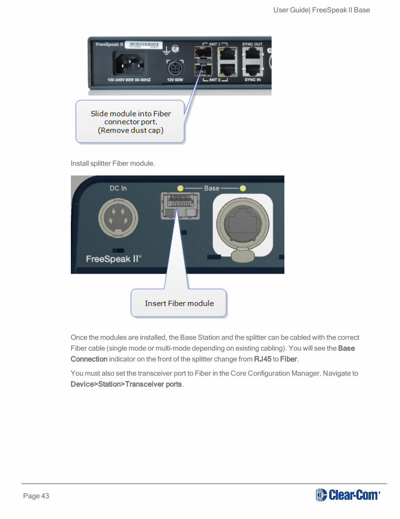
Install splitter Fiber module.
Page 35

User Guide| FreeSpeak II Base
Once the modules are installed, the Base Station and the splitter can be cabled with the correctFiber cable (single mode or multi-mode depending on existing cabling). You will see the BaseConnection indicator on the front of the splitter change from RJ45 to Fiber.
You must also set the transceiver port to Fiber in the Core Configuration Manager. Navigate toDevice>Station>Transceiver ports.
3.13 Transceiver sync compensation (cable compensation)
You must set transceiver sync compensation if the total cable length between transceivers isgreater than 500m / 1640 feet.
3.13.1 About transceiver sync compensationCable length needs to be calculated when the distance in total cable length between transceiversis greater than 500m/1640 feet. This is to prevent the DECT signals between transceivers frombecoming out of synchronization. If the transceivers are not synchronized, beltpack handover willnot happen effectively.
Page 36

User Guide| FreeSpeak II Base
Setting transceiver sync compensation is particularly important if you have overlapping transceivercoverage zones (RF cells) or the beltpacks need to move between coverage zones.
Example
Transceiver 1: total cable length = 100m / 328 feet.
Transceiver 2: total cable length = 850m / 2788 feet.
In this case, transceiver cable length should be set.
Set transceiver sync offset in the CCM:
Page 37

User Guide| FreeSpeak II Base
Set transceiver sync offset from the Base menus:
Page 38

User Guide| FreeSpeak II Base
4 Using the FreeSpeak II Basesplitter (FSII-SPL)The FreeSpeak II Base transceiver splitter is a device that connects up to five transceivers to aFreeSpeak Base (both FreeSpeak I and FreeSpeak II, 1.9 and 2.4 systems) or an Eclipse matrix.Using the splitter, audio can be routed from the Base to transceivers either via Cat5/6 Ethernetcable (RJ45) or a Fiber connection.
4.1 Configuration using a splitter with Cat 5/6 RJ45 connection
Page 39

User Guide| FreeSpeak II Base
4.2 Configuration using a splitter with fiber connection
The transceiver connections are switched between RJ45 and Fiber routing using dip switches setinside the splitter.
Page 40

User Guide| FreeSpeak II Base
Note: When using Fiber, you must install Fiber modules. See link below.
Note: When using the splitter with third party routing devices, transceiver synchronisation data is notpassed. In this case, you need to set the splitter to 'local synch' mode. This is done by setting thesplitter dip-switch no. 6 to OFF.
For more information, see:
l Install Fiber modules (parts # HLI-SMFO, HLI-MMFO) on page 42
l Printable Splitter Quick Start Guide.pdf
4.3 Splitter (FSII-SPL) rear connectors
Show me:
See also:
Splitter (FSII-SPL) front panel on page 42
Using the FreeSpeak II Basesplitter (FSII-SPL) on page 39
Page 41

User Guide| FreeSpeak II Base
4.4 Splitter (FSII-SPL) front panel
See also:
Splitter (FSII-SPL) rear connectors on page 41
Using the FreeSpeak II Basesplitter (FSII-SPL) on page 39
4.5 Using a transceiver with a fiber connection
You may wish to connect a FreeSpeak II Base to a splitter (FSII-SPL) using Fiber. In this case,you need to install Fiber modules to the Base and the splitter.
l Modules are available for single mode Fiber cable (HLI-SMFO) and multi-mode Fiber cable(HLI-MMFO)
l Modules are supplied as a pair, one for the Base Station and one for the splitter.
l Modules can be hot patched, no need to power off devices.
4.5.1 Install Fiber modules (parts # HLI-SMFO, HLI-MMFO)Install Base Station Fiber module.
Page 42
User Guide| FreeSpeak II Base
Install splitter Fiber module.
Once the modules are installed, the Base Station and the splitter can be cabled with the correctFiber cable (single mode or multi-mode depending on existing cabling). You will see the BaseConnection indicator on the front of the splitter change from RJ45 to Fiber.
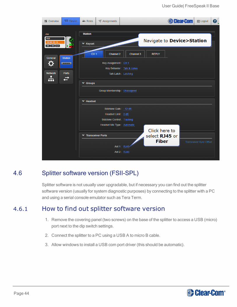
You must also set the transceiver port to Fiber in the Core Configuration Manager. Navigate toDevice>Station>Transceiver ports.
Page 43
User Guide| FreeSpeak II Base
4.6 Splitter software version (FSII-SPL)
Splitter software is not usually user upgradable, but if necessary you can find out the splittersoftware version (usually for system diagnostic purposes) by connecting to the splitter with a PCand using a serial console emulator such as Tera Term.
4.6.1 How to find out splitter software version1. Remove the covering panel (two screws) on the base of the splitter to access a USB (micro)
port next to the dip switch settings.
2. Connect the splitter to a PC using a USB A to micro B cable.
3. Allow windows to install a USB com port driver (this should be automatic).
Page 44

User Guide| FreeSpeak II Base
4. Using a serial console emulator (such as Tera Term), input serial console settings.
5. Open the serial console. Press the space bar and the splitter will output its software versionas shown.
Page 45

User Guide| FreeSpeak II Base
5 Registering beltpacksWireless beltpacks must be registered to your Base Station before you can use them with thetransceivers.
Roles must be available for beltpacks before you register them. Your system arrives with defaultRoles which can be used, or you can create your own.
There are two ways of registering beltpacks:
l Registering beltpacks using USB cable on page 47
l Register beltpacks over-the-air (OTA) on page 49.
Registering by USB cable is the quickest and easiest way.
Page 46

User Guide| FreeSpeak II Base
5.1 Registering beltpacks
Wireless beltpacks must be registered to your Base Station before you can use them with thetransceivers.
Roles must be available for beltpacks before you register them. Your system arrives with defaultRoles which can be used, or you can create your own.
There are two ways of registering beltpacks:
l Registering beltpacks using USB cable on page 47
l Register beltpacks over-the-air (OTA) on page 49.
Registering by USB cable is the quickest and easiest way.
5.2 Registering beltpacks using USB cable
You must have a USB A to micro USB B cable and the beltpacks to hand before you start.
1. Connect a beltpack to the Base Station using a USB A to micro USB B cable.
The beltpack can be powered on either before or after connection.
Page 47

User Guide| FreeSpeak II Base
The Base Station will show 'Beltpack is now registered' in the front menu screens.
2. Select an available Role from the beltpack screen.
Page 48

User Guide| FreeSpeak II Base
The beltpack is now registered and ready for use.
Note: A Role can be fixed to a beltpack. If you fix a Role to a beltpack, the beltpack automatically selectsthe Role on powering.
See also:
l Using Roles on page 70
l Unregister beltpacks on page 52
5.3 Register beltpacks over-the-air (OTA)
You can register beltpacks over-the-air from the CCM or the Base Station.
5.3.1 Start registration from the Base StationPress the MENU button on the base and navigate to: Administration>Beltpacks>Over TheAir>Start OTA. Press the rotary controller to start registration.
Page 49

User Guide| FreeSpeak II Base
5.3.2 Start registration from the CCMConnect to the CCM in a browser and navigate to Device>General>Wireless. Click the OTAbutton.
Note: Registration mode has a two minute inactive time-out. This is so several beltpacks can beregistered sequentially without the user having to re-enable registration mode.
5.3.3 Connect to systemNote: System = FreeSpeak II Base name.
On the beltpack to be registered, hold the menu key for two seconds to enter MENU options.Scroll to SYSTEM CONNECT using the rotary controllers and select it using key D. In menumode the D key on the beltpack operates as SELECT and the C key exits the menu level andcancels the selection.
Page 50

User Guide| FreeSpeak II Base
Note: On a new system there will be no previous connections at this point. However, if the beltpack iscurrently connected to an active system, a confirmation screen will appear. Select Yes to connectto a new system or No to remain connected to the current system.
Available systems and previously registered systems will be visible on the beltpack menu screen.
To connect the beltpack to the system, the system must be visible (V) and in registration (pairing)mode. If the system is not in registration mode (P visible), registration should be re-started (Step1).
Connect the beltpack to the system using key D.
5.3.4 Enter pairing codeEnter the four digit pairing code for the system using both rotary controllers and the menu selectkey (D). The default code is 0000.
Note: The O.T.A. pin code is available from the Base Station menus and the CCM. SeeAdministration/Beltpacks on the Base Station, Device/General/Wireless in the CCM.
Page 51
User Guide| FreeSpeak II Base
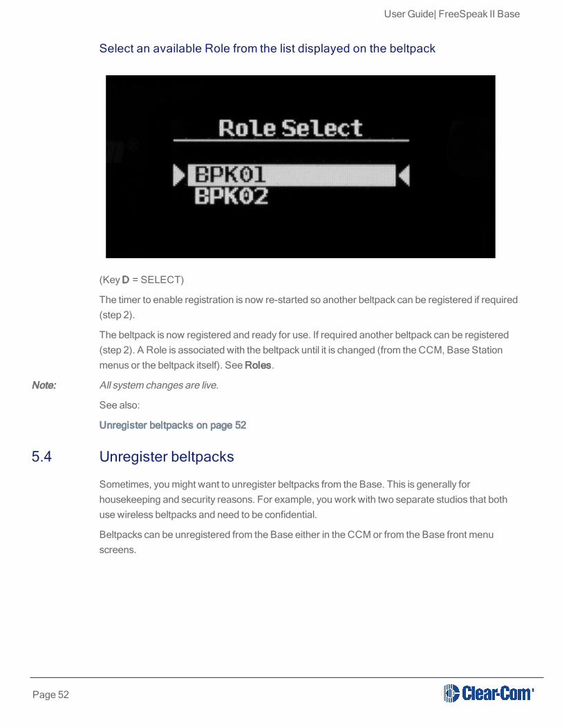
Select an available Role from the list displayed on the beltpack
(Key D = SELECT)
The timer to enable registration is now re-started so another beltpack can be registered if required(step 2).
The beltpack is now registered and ready for use. If required another beltpack can be registered(step 2). A Role is associated with the beltpack until it is changed (from the CCM, Base Stationmenus or the beltpack itself). See Roles.
Note: All system changes are live.
See also:
Unregister beltpacks on page 52
5.4 Unregister beltpacks
Sometimes, you might want to unregister beltpacks from the Base. This is generally forhousekeeping and security reasons. For example, you work with two separate studios that bothuse wireless beltpacks and need to be confidential.
Beltpacks can be unregistered from the Base either in the CCM or from the Base front menuscreens.
Page 52

User Guide| FreeSpeak II Base
5.4.1 Unregister beltpacks in the CCM
Page 53

User Guide| FreeSpeak II Base
5.4.2 Unregister beltpacks from the Base menu screens
Page 54

User Guide| FreeSpeak II Base
6 Using beltpacks
l Beltpacks are always configured using a Role. See Using Roles on page 70.
l Before they can be used, wireless beltpacks must be registered to the Base Station. This isdone either via USB or over-the-air (OTA). See Registering beltpacks on page 47.
l See Configuring audio routes in FreeSpeak II Base on page 89.
l See Unregister beltpacks on page 52
l See Powering your system on page 13
l See Beltpack settings on page 56
Page 55

User Guide| FreeSpeak II Base
6.1 Beltpack settings
Note: The default settings are shown in bold.
6.1.1 Keyset (audio assignment)This table shows what can be programmed to each FSII-Base beltpack key
Key A Key B Key C Key D Reply
KeyAssignment
Channel 1 Channel 1 - 12
Groups 1 - 12
Role 1 - XX (where XX is thenumber of Roles available)
Ports: PRGM, SA, Headset, 2WPartyline 1 - 4 , 4W digital partyline1 - 4
Channel 2 Channel 1- 12
Groups 1 - 12
Role 1 - XX (whereXX is the number ofRoles available)
Ports: PRGM, SA,Headset, 2WPartyline 1 - 4 , 4Wdigital partyline 1 - 4
Call Channel 1Channel 1 - 12
Groups 1 - 12
Role 1 - XX(where XX is thenumber of Rolesavailable)
Ports: PRGM,SA, Headset, 2WPartyline 1 - 4 ,4W digitalpartyline 1 - 4
Call Channel 2Channel 1 - 24
Groups 1 - 12
Role 1 - XX(where XX is thenumber of Rolesavailable)
Ports: PRGM,SA, Headset, 2WPartyline 1 - 4 ,4W digitalpartyline 1 - 4
Reply Channel 1 - 12
Groups 1 - 12
Role 1 - XX (whereXX is the number ofRoles available)
Ports: PRGM, SA,Headset, 2WPartyline 1 - 4 , 4Wdigital partyline 1 - 4
KeyBehavior
Talk only, Listen only,Talk andListen, Dual Talk and Listen,ForcedListen,Talk and Forced Listen
Talk only, Listenonly,Talk and Listen,Dual Talk andListen,ForcedListen,Talk andForced Listen
Varies,according to howkey has beenprogrammed
Varies,according to howkey has beenprogrammed
Talk only Listenonly,Talk and Listen,Dual Talk andListen,Forced Listen,Talk and ForcedListen
Page 56

User Guide| FreeSpeak II Base
This table shows what can be programmed to each FSII-Base beltpack key
Talk Latch Latching/Disabled Latching/DisabledLatching/Disabled
Latching/Disabled
Latching/Disabled
6.1.2 General settingsDescription Enter description for Role (optional)
Display brightness Very low - Very high
Dimmed tallies Enabled/Disabled
Latch Disabled Enabled/Disabled
Reply Auto-Clear 1 - 60 secs (10 sec)
Display Dim timeout 5 - 120 secs (30 sec)
Display Off timeout 5 - 120 secs (30 sec)
Listen Again timeout Off, 1 -240 mins (240 mins)
Listen Again record Off, 1 - 15 secs (15 secs)
6.1.3 Gain and level optionsType of Gain Range
Input Gain 15 dB tto -70 dB (0 dB)
Output Gain 15 dB to -70 dB (0 dB)
Line-In Volume 6 dB to -15 dB (0 dB)
Page 57

User Guide| FreeSpeak II Base
Type of Gain Range
Master Volume -o.4 dB to -69.9 dB (0 dB)
Min Master Volume Off, -24.9 dB, -11.0 dB, - 6.0 dB
6.1.4 HeadsetHeadset setting Range
Headset Limit 8 dB to -12 dB (0 dB)
Sidetone Level 0 dB to -24.9 dB (0 dB)
Mic Echo Cancellation Disabled/Enabled
6.1.5 Menu accessLevel/mode Settings
Menu Access Level Advanced/Normal/Basic/None
Display Mode Intercom Mode/Partyline Mode
Master Volume Mode Talk Keys/Master Volume
6.1.6 Alarm optionsAlarm type
Battery Alarm Mode Vibrate & Audible/Vibrate Only/Audible Only/Off
Low Battery Threshold 0% to 100% (10%)
Call Alert Mode Vibrate & Audible/Vibrate Only/Audible Only/Off
Page 58
User Guide| FreeSpeak II Base
Alarm type
Out Of Range Alarm Audio Only/Off
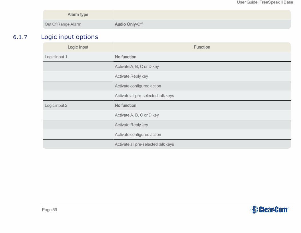
6.1.7 Logic input optionsLogic input Function
Logic input 1 No function
Activate A, B, C or D key
Activate Reply key
Activate configured action
Activate all pre-selected talk keys
Logic input 2 No function
Activate A, B, C or D key
Activate Reply key
Activate configured action
Activate all pre-selected talk keys
Page 59

User Guide| FreeSpeak II Base
6.2 Volume Operation
Volume operation on beltpacks can be set according to user preference. Control volume operationvia the beltpack's Role.
Volume Operation mode
MasterVolume
Rotary controllers adjust volume on all 5 beltpack keys
Talk KeysLeft rotary controller adjusts volume on A & B, right rotary controller adjustsvolume on C & D.
Page 60

User Guide| FreeSpeak II Base
6.2.1 How to control Volume Operation on beltpacks
Set Volume Operation from the Base station
Set Volume Operation in the CCM
Note: Volume Operation can also be set from the beltpack menu. Press and hold the menu button on thebeltpack to access menu options.
Page 61

User Guide| FreeSpeak II Base
6.2.2 Volume control on keys A & B, and D & CIn addition to the Volume Operation control feature, you can set the beltpack menu button toadjust how the volume controls work.
A quick tap on the menu button can perform two different functions.
Menu Key Operation (quick tap)
Menu KeyOperation mode1 (default)
trigger Listen Again
Menu KeyOperation mode2
Toggle rotary control volume adjust between A & B, and C & D. A beep willsound when controllers are switched. Toggle to C & D has a 10 secondinactive timeout.
To use this function, navigate to Menu Key Operation in Roles.
Set Menu Key Operation from the Base station.
6.3 Menu Key Operation
The menu button on beltpacks has several functions.
l A two second press allows the user to enter menu mode.
l A quick tap on the button can be configured in two different ways by setting 'menu keyoperation' in Roles. This quick tap functionality is called 'Menu Key Operation'.
Menu Key Operation has two settings:
l Trigger Listen Again (replays the last call to the beltpack).
l Switch volume control (A & B, C & D). This is the default setting.
Toggle beltpack rotary volume controls between A & B and C & D
Page 62

User Guide| FreeSpeak II Base
This feature allows the user to toggle rotary volume control between keys A & B, and C & D usinga quick tap of the menu button. This is helpful if you have different audio sources assigned to eachkey.
This mode has a 5 second inactive time-out, after which time to rotary controllers will revert tocontrolling volume on keys A & B. To re-activate this mode in order to adjust C & D, use anotherquick tap of the menu key. To switch quickly between A & B and C & D, tap the menu key to toggle.
6.3.1 Set Menu Key OperationThis feature can be set under Roles in the CCM, from the Base Station front menus and from thebeltpack itself (advanced menu options).
Set menu key operation in the CCM
Page 63

User Guide| FreeSpeak II Base
Set menu key operation from the Base Station menus
l Set menu key operation from the beltpack: Menu>Settings>Menu Key Oper.The beltpackmust have advanced menu options enabled (Roles>Select Role>Menu access).
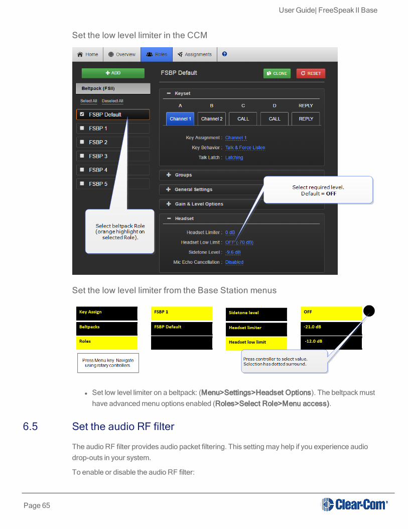
6.4 Master volume low level limiter (beltpacks)
This feature sets a low level limit in order to prevent beltpacks from being turned down so low theycannot be heard.
How this feature is used depends on your preferred working practice: it is possible to turn thevolume on the beltpack down so low that all audio is inaudible. This can cause confusion amongthe unwary, although some users may want to turn the volume down completely on occasion.
Values: , -6, -12, -21, -70 OFF. Default value = -70 OFF. If OFF, audio can be turned down so lowit cannot be heard at all.
6.4.1 Set beltpack low level limitThe low level limiter feature is set in Roles, from the CCM, The Base Station menus or from thebeltpack itself.
Page 64
User Guide| FreeSpeak II Base
Set the low level limiter in the CCM
Set the low level limiter from the Base Station menus
l Set low level limiter on a beltpack: (Menu>Settings>Headset Options). The beltpack musthave advanced menu options enabled (Roles>Select Role>Menu access).
6.5 Set the audio RF filter
The audio RF filter provides audio packet filtering. This setting may help if you experience audiodrop-outs in your system.
To enable or disable the audio RF filter:
Page 65

User Guide| FreeSpeak II Base
1. Navigate to Device > Wireless > Audio RF Filter.
2. Select Enabled or Disabled.
6.6 Configurable eavesdropping
Releases of FreeSpeak before FreeSpeak II Base left the beltpack mic permanently open,meaning that audio coming from the beltpack could be listeneed to even if the user had no activetalk routes. This feature can now be configured as required for each beltpack/Role in your wirelesssystem.
The default for FreeSpeak II Base and above is Eavesdropping disabled. However, earlierversions will revert to Eavesdropping enabled, the headset mic will remain open.
Page 66

User Guide| FreeSpeak II Base
6.6.1 How to set Eavesdropping function on beltpacksSet eavesdropping function in the CCM
Set eavesdropping function from the Base Station menus
6.7 AA Battery Type: Alkaline /NiMh
FreeSpeak II wireless beltpacks are supplied with Li-ion batteries and battery charger. However,in some cases you may wish to use AA batteries. Alkaline batteries can be used as a quick, easilyavailable replacement. NiMH batteries can be used in environments (for instance, highatmospheric/hyperbaric) where Li-ion batteries are prohibited.
Page 67

User Guide| FreeSpeak II Base
When using AA batteries of either kind, it is helpful to set battery type so that battery capacity canbe monitored accurately. NiMH batteries and alkaline batteries have different discharge patternsand setting this option will allow for that.
Default AA battery type = Alkaline.
6.7.1 How to set AA Battery Type
Set AA battery type from the Base station menus
Set AA battery type from the CCM
6.8 Accessing beltpack Admin menu
To access the beltpack Admin menu:
1. Press and hold the Menu button on the beltpack for two seconds.
2. Navigate to Settings > Admin options.
Page 68

User Guide| FreeSpeak II Base
3. Enter the pin code: 1111
The Admin menu appears.
Page 69

User Guide| FreeSpeak II Base
7 Using Roles
7.1 About FreeSpeak II Base II Roles
Use Roles to program beltpack keys with audio and related settings.
A Role is a pre-configured setting, designed to enable rapid system set-up. You will alwaysprogram audio and related settings for each beltpack via it's Role. Your FreeSpeak II Base arriveswith default Roles for all your beltpacks (5 or 25 beltpacks according to product and licence).
In FreeSpeak II Base each beltpack has its own Role, and you must have enough Roles beforeyou power beltpacks on. Use the pre-defined Roles, edit the pre-defined Roles, clone existingRoles or create new ones as required.
A Role cannot be used twice in FreeSpeak II Base II.
The default Role (which can be edited) uses Channel 1 and 2. Roles also contain settings such asvolume, key latching, menu access, Talk and Listen behavior (key behavior) and alerts.
Note: While the purpose of Roles is always to enable fast set-up, how Roles work is influenced byunderlying system architecture. This means that they work slightly different across Clear-Comproducts. Refer to your system documentation for guidance.
7.2 Default Role settings
Page 70

User Guide| FreeSpeak II Base
Your FreeSpeak II Base system arrives with default Roles which can be used 'as is'. The defaultsetting puts all beltpacks and the Base headset into Channel 1 and 2, where they talk and listenin a conference or Partyline set up. Simply register the beltpacks to the Base and select the nextavailable Role when you power the beltpack on.
To use pre-defined Roles, simply select the next available Role for your beltpack when it powersup.
Note: Beltpacks must be registered to the Base before a Role can be selected.
Note: The default Role can be changed to suit your requirements. It can also be reset to factorysettings.
See also:
Beltpack settings on page 56.
Registering beltpacks on page 47
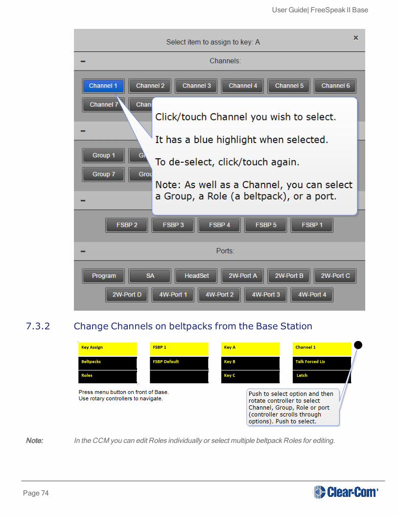
7.3 Changing Channels on beltpacks
To change the Channel on a beltpack, edit the Keyset of that beltpack. This is the same basicprocess from both the CCM and the Base Station. You must:
Page 71

User Guide| FreeSpeak II Base
l Select the Role (the beltpack configuration map)
l Select the key to change
l Change the audio assignment on the key.
Page 72

User Guide| FreeSpeak II Base
7.3.1 Change Channels on beltpacks in the CCM
Page 73
User Guide| FreeSpeak II Base
7.3.2 Change Channels on beltpacks from the Base Station
Note: In the CCM you can edit Roles individually or select multiple beltpack Roles for editing.
Page 74

User Guide| FreeSpeak II Base
7.4 Change beltpack settings
You can change of the available settings either in the online configuration manager (CCM) orfrom the Base menu screens (navigate to Roles in the first menu screen). To see what can bechanged, see Beltpack settings on page 56 or explore the Roles page in the CCM. Each pagein the CCM has context sensitive help: press ? in the navigation bar.
Note: In the CCM you can edit Roles individually or select multiple beltpack Roles for editing.
Changes you make from the CCM or the Base Station front menu screens are live.
7.5 How to create Roles for beltpacks
You can work with the default Roles, or create new ones. Roles can be deleted.
7.5.1 Create Roles in the CCM
You can now use the drop-down menus to edit the settings for the new Role. For a list ofconfigurable settings, see Beltpack settings on page 56.
Page 75

User Guide| FreeSpeak II Base
7.5.2 Create Roles from the Base Station menus
To use the Roles you create, simply select the Role from your beltpack when it is powered up.You cannot select a Role twice.
Note: Beltpacks must be registered to the Base before a Role can be selected.
You can now use the Base Station menus to edit the settings for the new Role. For a list ofconfigurable settings, see FreeSpeak II Base Station menu 'at-a-glance' guide on page 18.
7.6 Save Settings
You can save your Role configuration to a USB or directory. We advise that you do this. Saving
Page 76

User Guide| FreeSpeak II Base
settings will save Role, Base Station and transceiver configuration.
Page 77

User Guide| FreeSpeak II Base
7.6.1 How to save settings from the CCM
Page 78

User Guide| FreeSpeak II Base
7.6.2 How to save settings from the Base Station menus
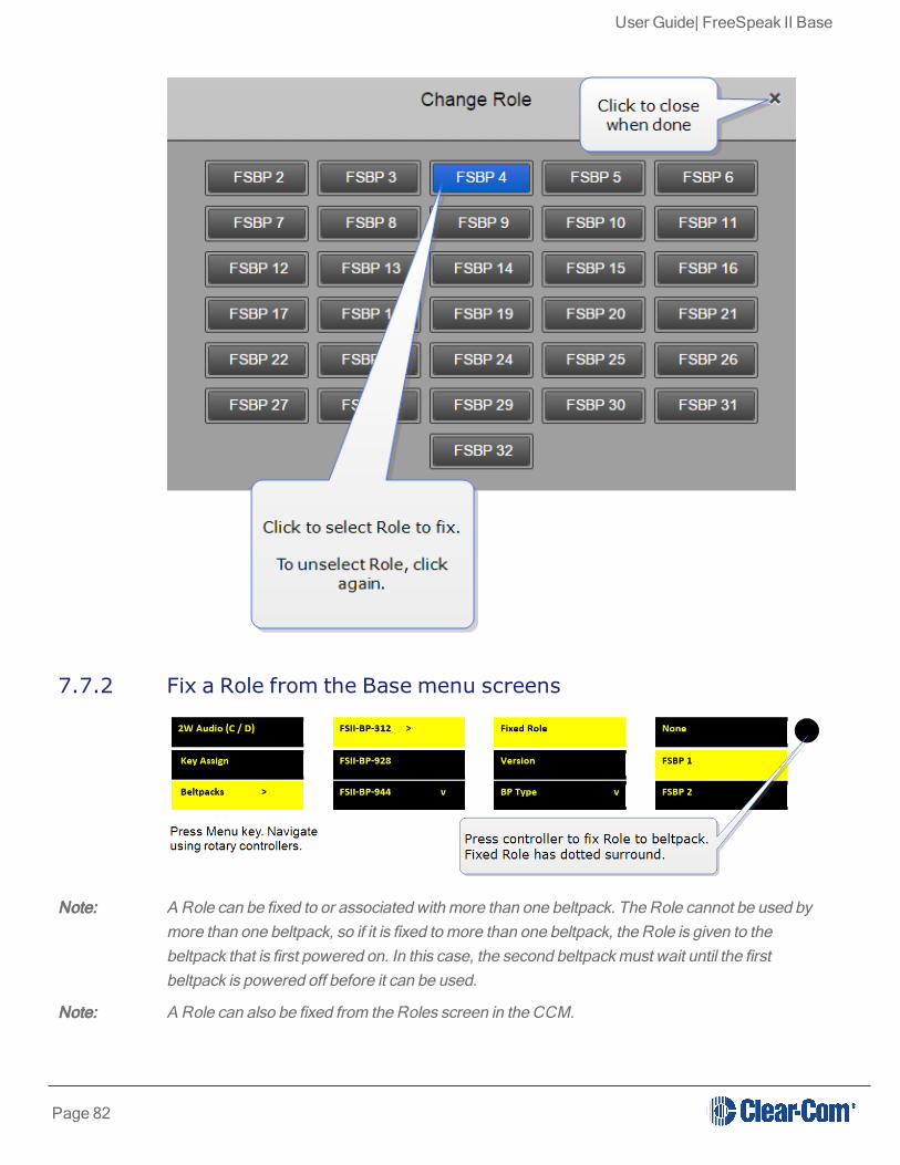
7.7 Fixed Roles
A fixed Role fixes a Role to a beltpack. This means that the beltpack user does not have to selecta Role when they power up the device, as a Role is selected automatically.
A Role can be:
l Not associated with a beltpack. In this case, the user can select any available Role.
l Fixed to a beltpack. In this case, the user has no choice but to use the fixed Role.
l Associated with a beltpack but not fixed. The user will be offered the associated Rolewhen powering on the beltpack but does not have to take it.
For a beltpack to have a fixed Role, it must be already registered to the base. The Role is fixed tothe beltpack, either from the CCM or the Base menu screens.
Page 79

User Guide| FreeSpeak II Base
7.7.1 Fix a Role from the CCM
Page 80

User Guide| FreeSpeak II Base
Page 81
User Guide| FreeSpeak II Base
7.7.2 Fix a Role from the Base menu screens
Note: A Role can be fixed to or associated with more than one beltpack. The Role cannot be used bymore than one beltpack, so if it is fixed to more than one beltpack, the Role is given to thebeltpack that is first powered on. In this case, the second beltpack must wait until the firstbeltpack is powered off before it can be used.
Note: A Role can also be fixed from the Roles screen in the CCM.
Page 82
User Guide| FreeSpeak II Base
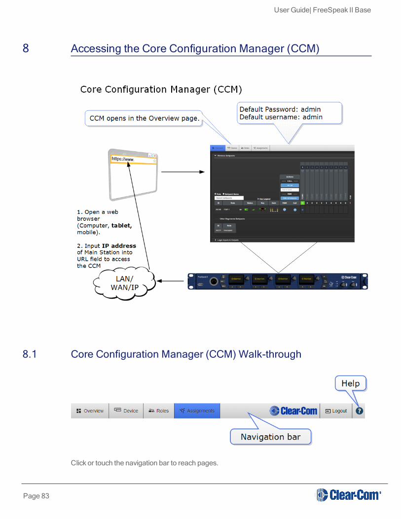
8 Accessing the Core Configuration Manager (CCM)
8.1 Core Configuration Manager (CCM) Walk-through
Click or touch the navigation bar to reach pages.
Page 83

User Guide| FreeSpeak II Base
For context sensitive help, click/touch the help button (?).
8.1.1 Overview PageThis screen is the diagnostics screen for your FreeSpeak II Base system. It gives a live overview oftransceivers and beltpacks in your system.
Click on any device in this page to access information and configuration options. Click on blue textfields to edit.
Note: All system changes are live.
l Transceivers 1 - 5: transceiver port 1 on Base Station
l Transceivers 6 - 10: transceiver port 2 on Base Station
8.1.2 Device pageThe Device page is where you find configuration options specific to your Base Station.
Page 84

User Guide| FreeSpeak II Base
8.1.3 Roles PageThe Roles page is where you assign audio to beltpacks and configure a beltpack's settings.
Roles are pre-configurations: default audio routes and settings that are applied to your devicewhen it is first powered up (a Role is selected by the beltpack user). The default Role can be editedand/or reset to default. Individual Roles can be edited, deleted, cloned and created.
In FreeSpeak II Base a Role is attached to a specific beltpack in a one-to-one relationship. Thedefault Role puts Channel 1 and 2 on beltpack keys A and B, with C and D set as call keys. TheReply key can be re-assigned to a Channel as required.
Page 85

User Guide| FreeSpeak II Base
On the Roles page you can edit, create, clone and delete Roles.
All Roles can be edited as required.
You can save your Roles to a USB stick or directory for convenience (advised).
Page 86

User Guide| FreeSpeak II Base
8.1.4 Assignments PageOn this page you see audio assignment in Channels. This screen is a live representation of anyonetalking or listening in up to 24 Channels. You can toggle between Roles view and Hostname view.Hostname view can be used to show individual beltpack hardware.
Page 87

User Guide| FreeSpeak II Base
See also:
Accessing the Core Configuration Manager (CCM) on page 83
What is a Keyset? on page 6
Configuring audio routes in FreeSpeak II Base on page 89
Page 88

User Guide| FreeSpeak II Base
9 Configuring audio routes in FreeSpeak II BaseThere are many ways to configure FreeSpeak II to route audio.
9.1 Channels
In FreeSpeak II Base, audio routes can be made between beltpacks and external interfaces byputting all members (audio feeds and beltpacks) in a Channel together. In this way, beltpacks,audio and the controller all communicate with each other. A Channel operates as a Partyline orconference.
You can see all active sources in a Channel or Group in the Assignments page.
Note: Channels are set to 'Talk and Forced Listen' by default. See Key behavior on page 8 for moreinformation.
9.2 Groups
Audio can also be configured into Groups. Groups are programed in a similar way to Channels;
Page 89

User Guide| FreeSpeak II Base
simply assign the audio sources to the Group (Group Members) and then program a key to talk tothe Group. Ports, the Base headset, and beltpacks can all become Group members. Once aGroup member, users will be able to hear announcements to the Group, and reply using the Replykey.
Note: You can see all members of a Group at a glance in the Assignments page of the CCM. Navigate toAssignments and click the Group tab. Beltpacks will not be visible in the Group until they areonline.
9.3 Channel or Group?
Both Channels and Groups are essentially digital containers for digital audio sources, allowingcommunication between members.
9.3.1 ChannelA Channel operates as an intercom Partyline or conference. All members can talk to and listen toall other members, as long as they have keys to do so.
Page 90

User Guide| FreeSpeak II Base
Page 91

User Guide| FreeSpeak II Base
Note: The default key behavior setting for a member of a Channel is Talk and Forced Listen. See Keybehavior on page 8 for more information.
You can see Channel members in the Assignments page of the CCM. Navigate to Assignments.
9.4 Group
A Group configuration enables an announcement or broadcast to a number of memberssimultaneously.
Page 92

User Guide| FreeSpeak II Base
A group member can reply directly to the announcer using the Reply key. The other groupmembers will not hear this.
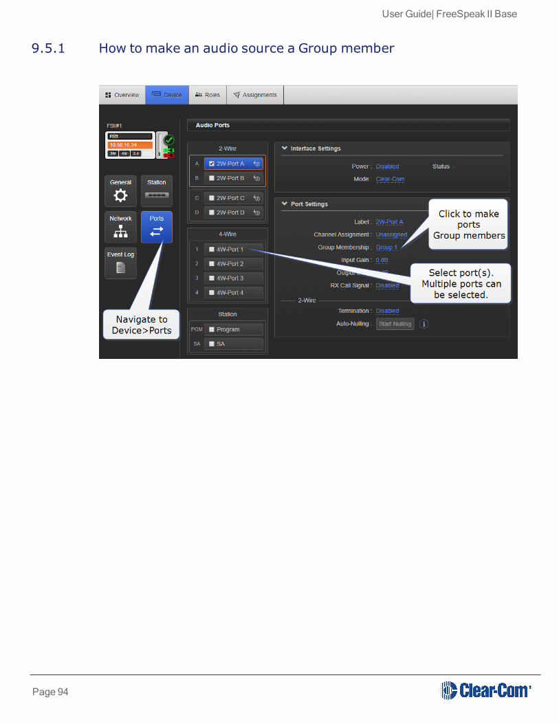
9.5 Example Group set-up
To set up a Group you must first put the members in the Group. Ports, Beltpacks and the Baseheadset can all become members of a Group. When the members of the Group are assigned, youmust program a key to talk to the Group members.
Page 93
User Guide| FreeSpeak II Base
9.5.1 How to make an audio source a Group member
Page 94

User Guide| FreeSpeak II Base
9.5.2 How to program a Talk key to the Group
Note: The default key behavior setting for a talk key to a Group is 'Talk Only'. See Key behavior onpage 8 for more information.
You can see Group members in the Assignments page of the CCM. Navigate to Assignmentsand click/touch the Groups tab. Beltpacks will only be visible in the Group when they are online.
9.6 Example audio assignment
Follow steps 1. to 3. to connect audio from external devices to the Base Station, populateChannels and and set up communication with beltpacks.
1. Connect 2-Wire or 4-Wire audio devices to interfaces/ports.
Page 95

User Guide| FreeSpeak II Base
2. Assign interfaces/ports to Channels.
Setting audio on interfaces/ports can be done from the CCM or the Base Station:
a. Port assignment in the CCM.
Page 96

User Guide| FreeSpeak II Base
b. Port assignment from the Base Station menu screens
Note: You can also assign a port to a Channel or Group in the Assignments page of the CCM.
9.7 Assign Channels to beltpack keys (A, B, C, D, Reply)
Audio assignment for beltpacks is always done with a Role. A Role is a pre-defined beltpackconfiguration map. You select a Role for a beltpack when it is first powered on. The Role abeltpack is using can be changed from the Base station, the CCM or the beltpack itself.
In the first case, it is easiest to use the default Role. This puts Channel 1 and Channel 2 on to thebeltpack keys. See Default Role settings on page 70 for how to do this.
Page 97

User Guide| FreeSpeak II Base
To change the Channel on a beltpack you need to edit the Role that beltpack is using. Find thebeltpack Role name at the bottom of the beltpack screen:
Page 98

User Guide| FreeSpeak II Base
9.7.1 How to edit beltpack Role in the CCM
Page 99

User Guide| FreeSpeak II Base
9.7.2 How to edit beltpack Role from the Base Station menu screens
Note: You can assign audio to keys C, D and Reply. To return the status of these keys to Call andReply, you must deselect or unassign the audio assignment. A selected assignment turns blue
Page 100

User Guide| FreeSpeak II Base
in the CCM. Click on a blue assignment again to deselect it. From the Base Station menuscreens go to Key Assign/Role/Key/Unassigned.
See also:
Registering beltpacks
Roles
9.8 Change Channel settings on the Base Station
The Base Station default setting has Channels 1 - 3 on the first three Keysets. The 4th Keyset isa Reply key.
The Base Station default setting can be edited.
Page 101

User Guide| FreeSpeak II Base
9.8.1 Change Base Station key assignment from the CCM
Page 102
User Guide| FreeSpeak II Base
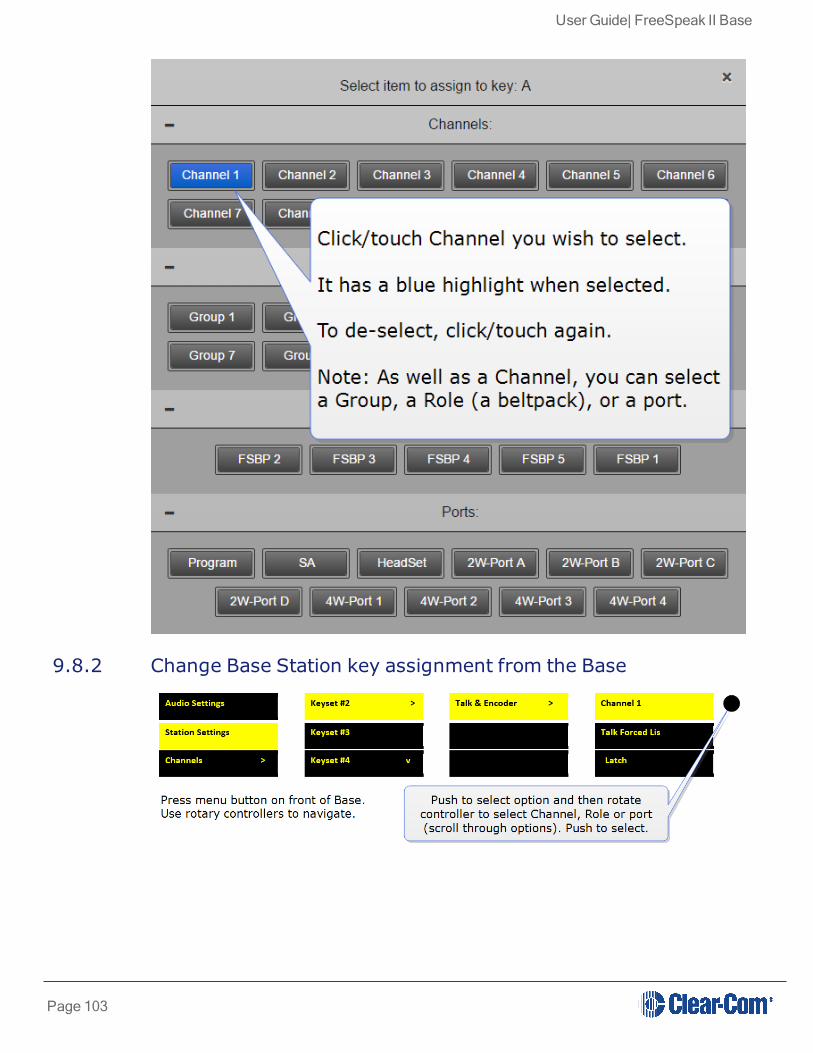
9.8.2 Change Base Station key assignment from the Base
Page 103

User Guide| FreeSpeak II Base
9.9 Configure a one-to-one connection
As well as into Channels, audio can be configured in a point-to-point relationship (for instance, onebeltpack to another in a private communication).
9.10 Example point-to-point audio assignment
When selecting an audio source for any key, (in this example key C on a beltpack), instead ofselecting a Channel, select a beltpack Role or port.
This creates a point-to-point connection. A similar effect could be achieved by putting twobeltpacks into a Channel of their own.
Page 104

User Guide| FreeSpeak II Base
10 Interconnecting intercom systemsYou can connect FreeSpeak II Base to a range of intercom systems.
l Clear-Com Encore and RTS (2-wire cabled partyline systems)
l DX210 (2-wire/4-wire systems)
l Eclipse (digital matrix systems)
l HelixNet (digital partyline)
l Two-way radio systems
l FreeSpeak II Base can be connected to another FreeSpeak II Base station in order to shareChannels between two Bases, increasing the range of your system.
10.1 How do I connect to other intercom devices?
When connecting FreeSpeak II Base to other intercom devices, the general process is the same,though there are details that change according to device type. As a general guideline you need to:
1. Configure the relevant interface (port) settings (see below)
2. Connect the device with CAT5 or microphone cable
3. Adjust audio levels as required
10.2 Connecting 2-wire equipment
When connecting 2-wire equipment the following functions should be taken into consideration:
l Auto-null. Every time equipment is changed on a 2-wire interface (port) you should runauto-null.
l Enable/disable the partyline power. Do this in Ports/2-Wire. Default setting: Disabled.
l Enable/disable Line termination. The line should only be terminated once on interconnecteddevices, do not terminate on more than one piece of equipment. Default setting: Disabled.
These functions can be set either in the 2-wire port settings page of the Core ConfigurationManager (CCM) or from the front panel screens on the Base Station.
10.3 Connecting to 4-wire equipment
When connecting to 4-wire equipment the following need to be taken into account:
Page 105

User Guide| FreeSpeak II Base
l To minimise noise, use screened (shielded) cable when connecting 4-wire ports.
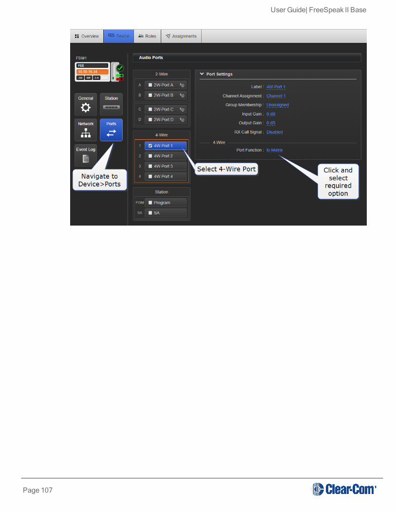
l Pin-out configuration (mode) can be set on all FreeSpeak II Base 4-wire interfaces. This is asoftware switch that switches the configuration of the pins on the RJ45 etherCONconnectors, according to the device you are connecting to. Default setting: To Matrix. SeePort Function.
10.4 Port Function
Clear-Com products are designed so matrices can connect directly to panels/Base Station/mainstation using a straight-through CAT 5/6 (Ethernet) cable. The pin assignments (inputs andoutputs) on these devices are complementary. Previously, a crossover cable was necessary whenconnecting Bases to other Bases. It is no longer necessary to use a crossover cable as there isnow a Port Function toggle which changes pinouts as required. This is function is found in portoptions and can be set from the CCM or the Base Station front panel menus.
10.4.1 Pin Assignments
Port Function pin assignments
Pin To Panel/Base Station To Matrix
1 Data in + Data out +
2 Data in - Data out -
3 Audio in + Audio out +
4 Audio out + Audio in +
5 Audio out - Audio in -
6 Audio in - Audio out -
7 Data out + Data in +
8 Data out - Data in -
When connecting one FreeSpeak II Base to another FreeSpeak II Base, one device must beset To Matrix and the other To Panel.
10.4.2 How do I set Port Function (pin polarity)?Set Port Function in the CCM
Page 106
User Guide| FreeSpeak II Base
Page 107

User Guide| FreeSpeak II Base
11 Using General Purpose inputs and outputs (GPIOs)FSII Base II v.2 and above offers six fully configurable GPIOs, increasing the range and possibleuses of controls and relays.
Earlier versions have limited GPIO functionality (an output fires on Stage Announce only).
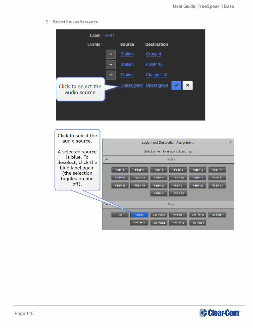
l 2 x GPIs. These can be used, for example, to allow the station operator to open an audioroute to a Channel using a foot switch, or to route a program feed to a Channel, Group orbeltpack when an on-air light comes on. Each input control can be used to generate up to 10different audio routes.
l 4 x GPOs. The most common uses for output relays are to turn on an on-air light, connect toa radio and send an input to an external audio console. Each GPO can be used to generateup to 10 different actions.
Relays and GPIOs are configured in the General page of the Core Configuration Manager(CCM).
11.1 How to configure a GPI when using FSII Base II
1. In the CCM, navigate to Device>General.
Page 108

User Guide| FreeSpeak II Base
Page 109
User Guide| FreeSpeak II Base
2. Select the audio source.
Page 110

User Guide| FreeSpeak II Base
3. Select the audio destination
4. Name the GPI
Page 111

User Guide| FreeSpeak II Base
In this example, an audio connection will be created between the Base Station headset andthe destinations (Channel, beltpack, and port) whenever Footswitch generates an input.
The GPI trigger can be seen in the Overview page of the CCM.
Page 112

User Guide| FreeSpeak II Base
Note: Each GPI can be used to generate up to 10 different audio routes.
11.2 How to configure a GPO when using FSII Base II
1. In the CCM navigate to Device>General.
Page 113
User Guide| FreeSpeak II Base
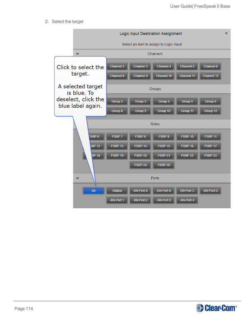
2. Select the target
Page 114

User Guide| FreeSpeak II Base
3. Select the behavior that triggers the GPO.
In this example, where the target is set to Stage Announce, and the behavior is set to Talk , anoutput trigger is sent whenever the Stage Announce button on the Base is pressed. This replicatesexisting functionality, but the GPOs can be set to any configuration you require. You can set up to10 actions on each GPO.
The GPO can be seen in the Overview page of the CCM.
Note: Each GPO can be used to generate up to 10 different actions.
11.3 Test GPIOs
The configuration of the GPIOs can be tested (without connecting an external device) in theOverview page of the CCM.
Page 115

User Guide| FreeSpeak II Base
For more information, see:
GPIO/DB15 connector (K) on page 12
11.4 Control Events
When using FreeSpeak II, Control Events are used to trigger an event on an action (usually acrosspoint).
For example, the system can be configured to send a call signal to turn on an FOR22 radio when abeltpack talks in a channel.
To use Control Events you must select a source and a destination and then set the type of actionyou want to happen when the source contacts the destination.
Possiblesource type
Possibledestination type
Action type Details
l Channel
l Group
l Beltpack
l Port
l Channel
l Group
l Beltpack
l Port
l GPO. There are 4 GPOs tochose from.
l Call. A call signal is sentautomatically from thedestination.
l Chose from 1– 4.
l No furtheractionrequired.
Page 116

User Guide| FreeSpeak II Base
Possiblesource type
Possibledestination type
Action type Details
l Xpt.l Set new
source anddestination.
11.4.1 Control Events, example configurationsTo set Control Events, in the CCM navigate to Device>General>Control Events. Set the source,destination and action type as required.
1. Configure trigger for an FOR22 radio (example)
Source DestinationAction
typeAction details
Channel1
2-wire or 4-wire port
CallNo configuration necessary. A call signal is automatically sentfrom the port and this activates the FOR22.
2. Turn on an on-air light when the Base Station user talks to Channel 2 (example)
Page 117

User Guide| FreeSpeak II Base
Source Destination Action type Action details
Station Channel 2 GPO GPO2 fires when Station talks to Channel 2
Page 118

User Guide| FreeSpeak II Base
12 Upgrading your devicesTo upgrade your devices, you will need to import the upgrade file provided by Clear-Com into theunit. The Base, the beltpacks and the transceivers can all be upgraded from the Coreconfiguration Manager (CCM). The prcedure is the same for each device type. The Base can beupgraded via USB from the Base Station menus.
Device type File type (where xxxx = revision no.)
Base Station FSII_xxxxx.gz
Beltpack PP_xxxxx.FWW
Transceiver RFP_xxxx.FWW
12.1 How to upgrade your devices
You can upgrade your devices from the CCM or from the Base Station.
Page 119

User Guide| FreeSpeak II Base
12.1.1 From the CCM
Page 120

User Guide| FreeSpeak II Base
12.1.2 From the Base Station menus
Note: The Base Station only can be upgraded from the Base Station menus. Transceivers and beltpacksmust be upgraded using the CCM
See also:
Accessing the Core Configuration Manager (CCM) on page 83
Note: The FSII splitter is not user upgradable. Contact HME Clear-Com Ltd if you need moreinformation.
Page 121

User Guide| FreeSpeak II Base
13 Specifications
13.1 Base Station
Specification ValueBase Station tobeltpack frequencyresponse
100 - 7.1 Hz
Number of FS IIbeltpacks per BaseStation
5 (FS-BASE-II-5) or 25 (FS-BASE-II), depending on model
Number oftransceivers (FS-TA) supported byBase Station
2 direct or 10 via transceiver splitters
Number oftransceiver ports
2 x RJ45 & 2 x Fiber (2 active at any time)
Programming port 2 x LAN
GPIO port
DB15:
l 4 x relay outputs, normally open and normally closed wiring
l 2 x GPI
Partyline: A,B,C,Dl XLR-3F, ON/OFF termination control.
l Power ON/OFF (A/B, C/D paired)
4 -wire 4 X RJ45 for 4-wire
Program inputXLR-3F, transformer isolated, line-level input, indpendent Program Inputlevel control via rotary encoder
Stage Announceoutput
XLR-3M, transformer isolated, line-level output with dedicated front panelTalk key
Front panelheadset
4-pin (or 5-pin male connector depending on model. Automatic mic detect
4 x programmable l 128 x 64 OLED
Page 122
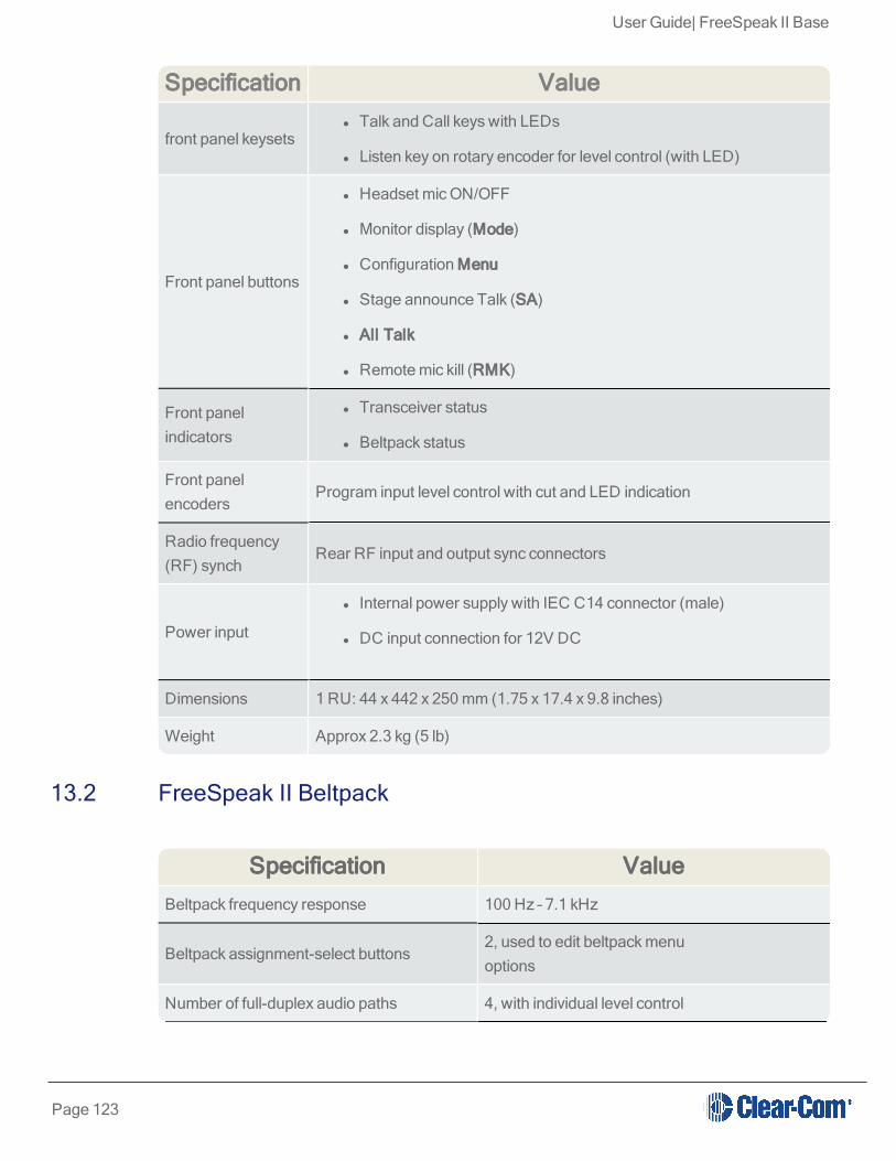
User Guide| FreeSpeak II Base
Specification Value
front panel keysetsl Talk and Call keys with LEDs
l Listen key on rotary encoder for level control (with LED)
Front panel buttons
l Headset mic ON/OFF
l Monitor display (Mode)
l Configuration Menu
l Stage announce Talk (SA)
l All Talk
l Remote mic kill (RMK)
Front panelindicators
l Transceiver status
l Beltpack status
Front panelencoders
Program input level control with cut and LED indication
Radio frequency(RF) synch
Rear RF input and output sync connectors
Power input
l Internal power supply with IEC C14 connector (male)
l DC input connection for 12V DC
Dimensions 1 RU: 44 x 442 x 250 mm (1.75 x 17.4 x 9.8 inches)
Weight Approx 2.3 kg (5 lb)
13.2 FreeSpeak II Beltpack
Specification ValueBeltpack frequency response 100 Hz – 7.1 kHz
Beltpack assignment-select buttons2, used to edit beltpack menuoptions
Number of full-duplex audio paths 4, with individual level control
Page 123

User Guide| FreeSpeak II Base
Specification ValueLevel/Talk controls 2 top-mounted rotary encoders
Headset connector XLR-4M, Clear-Com standard
Headphone impedance 2 ohm to 2000 ohm
Microphone type Dynamic or electret, selectable in beltpack menu
Input level -70 to -40 dBu
Electret headphone voltage 2.3V
Microphone and headset limiters Selectable in beltpack menu
Powering Li-Ion Battery, 3 AA alkaline cells
Battery charging In unit, via supplied 5 way AC60 charger
Battery life Approximately 18 hours
Range from single FSII-TCVR-19transceiver
500 m from transceiver/transceiver in line-of-sight conditions; 50 m indoors; use multipletransceivers for larger, custom coverage areas.
Approx. dimensions 38 x 130 x 100 mm (dwh) (1.5 x 5 x 3.75 inches)
Weight (with batteries) Approx. 400g (9 oz)
13.3 FreeSpeak II Transceiver
Specification Value
Beltpacks supported per transceiverl FSII 1.9 GHz devices:5 in one cellular zone
l FSII 2.4 GHz devices:4 in one cellular zone
Transceiver transmission range Up to 500 m (1475 ft), line of sight
Maximum distance, matrix to transceiver viamatrix port
l 800 m (2625 ft.) using shielded 24 AWGcable.
l 400 m (1312 ft) using shielded 26 AWG
Local Powering Via 24VDC power supply
Mounting 3 fixing holes
Dimensions 50 x 140 x 175 mm (dwh)
Page 124

User Guide| FreeSpeak II Base
Specification Value(2.0 x 5.5 x 6.9 inches)
Weight Approx. 460g (16.1 oz)
13.4 FreeSpeak II Splitter
Specification ValueNumber of transceivers supported 10
Number of splitters per Base Station 2
Connection between Base Station andsplitter
4-pair shielded CAT5 cable with RJ-45
Connection between splitter and transceiver 4-pair shielded CAT5 cable with RJ-45
Powering of splitterLocally powered via external powersupply
13.5 Transmission Method
Specification Value
Method of RF operationDECT and ISM standards, using two DECTbandsper beltpack
Modulation GFSK
Frequencies of operation
l FSII 1.9 GHz1880–1900 MHz (Europe),1920 – 1930 MHz (North America)
l FSII 2.4 GHz2400–2480 MHz (Europe and NorthAmerica)
Maximum RF output
l 250 mW burst, average level 2 - 4 mW(Europe)
l 100 mW burst, average level 2 - 4 mW(US)
Page 125

User Guide| FreeSpeak II Base
Specification Value
Theory of Operation
Dynamic allocation of frequencies and handoff ofbeltpacks among the transceiver/transceivers upto their individual limit of 5 connected beltpacks ata time; each beltpack is assigned a “virtual port”within the matrix.
13.6 Notice about Specifications
While Clear-Com makes every attempt to maintain the accuracy of the information contained in itsproduct manuals, that information is subject to change without notice. Performance specificationsincluded in this manual are design-center specifications and are included for customer guidanceand to facilitate system installation. Actual operating performance may vary.
Page 126

User Guide| FreeSpeak II Base
14 Regulatory complianceApplicant Name: Clear-Com LLC
Applicant Address: 1301 Marina Village Pkwy, Suite 105, Alameda CA 94501, United States
Manufacturer Name: Clear-Com LLC
Manufacturer Address: 1301 Marina Village Pkwy, Suite 105, Alameda CA 94501, United States
Country of Origin: USA
Brand: Clear-Com
Caution: All products are compliant with regulatory requirements detailed in this document whenthe user follows all installation instructions and operating conditions per Clear-Com specifications
Caution: Use of accessories and peripherals other than those recommended by Clear-Com mayvoid the product's compliance as well as the user's authority to operate the equipment.
14.1 FCC Notice
This device complies with Part 15 of the FCC rules. Operation is subject to the following twoconditions: (1) This device may not cause harmful interference, and (2) This device must acceptany interference received, including interference that may cause undesired operation.
NOTE: This equipment has been tested and found to comply with the limits for a Class A digitaldevice, pursuant to Part 15 of the FCC rules. These limits are designed to provide reasonableprotection against harmful interference when the equipment is operated in a commercialenvironment. This equipment generates, uses and can radiate radio frequency energy and, if notinstalled and used in accordance with the instruction manual, may cause harmful interference toradio communication. Operation of this equipment in a residential area is likely to cause harmfulinterference, in which case the user will be required to correct the interference at his own expense.
Changes or modifications not expressly approved by Clear-Com, LLC, an HM Electronics, Inc.company could void the user’s authority to operate this equipment.
14.2 FCC/IC/EC RF Exposure Warning
- This product complies with FCC/IC/EC radiation exposure limits set forth for an uncontrolledenvironment.
- This product may not be co-located or operated in conjunction with any other transceiver ortransmitter.
Page 127

User Guide| FreeSpeak II Base
- The beltpack has been tested to comply with FCC/IC/EC RF Exposure requirements in body-worn position. Use of third party clips or holsters with the beltpack may not ensure compliance withFCC/IC/EC RF exposure requirements and should be avoided.
- To comply with FCC/IC/EC RF exposure requirements, the Antenna/Transceiver unit must beinstalled and operated at least 20 cm (8 inches) from any person.
14.3 Industry Canada Compliance Statement
This Class[A] digital device complies with Canadian ICES-003.
Avis de conformité à la réglementation d'Industrie Canada
Cet appareil est conforme aux CNR d’Industrie Canada applicables aux appareils radio exemptsde licence. L’exploitation est soumise aux deux conditions suivantes:
(1) cet appareil ne doit pas provoquer d’interféence, et
(2) cet appareil doit accepter toute interféence radioéectrique subie, mêe si l’interféence estsusceptible d’en compromettre le fonctionnement.
Cet éetteur exempt de licence est éuipéd’une antenne intéré. Cet éetteur exempt de licence n’estpas autoriséàfonctionner avec une autre antenne.
Cet appareil numérique de la class[*] est conforme à la norme NMB-003 du Canada.
14.4 Korean Notice
A급기기 (업무용방송통신기자재)
이기기는업무용(A급)으로전자파적합기기로
서판매자또는사용자는이점을주의하시기
바라며 ,가정외의지역에서사용하는것을목
적으로합니다 .
14.5 KCC 2.4Ghz warning
해당무선설비는전파혼신가능성이있으므로인명안전과관련된서비스는할수없음
14.6 European Union (CE mark)
The CE marking indicates compliance with the following directives and standards, wheneverapplicable to the product in question.
Directives:
- Radio Equipment Directive 2014/53/EU
Page 128

User Guide| FreeSpeak II Base
- Electromagnetic Compatibility Directive 2014/30/EU
- Low Voltage Directive 2014/35/EU
- RoHS Directive 2011/65/EU
Standards:
- EN55022/EN55032
- EN55024
- IEC/EN60950-1
- EN300328
- EN301406
- EN301489
- EN50581
Warning:
This is a Class A product. In a domestic environment this product may cause radio interference inwhich case the user may be required to take adequate measures.
14.7 Waste Electrical and Electronic Equipment (WEEE)
The European Union (EU) WEEE Directive (2012/19/EU) places an obligation on producers(manufacturers, distributors and/or retailers) to take-back electronic products at the end of theiruseful life. The WEEE Directive covers most Clear-Com products being sold into the EU as ofAugust 13, 2005. Manufacturers, distributors and retailers are obliged to finance the costs ofrecovery from municipal collection points, reuse, and recycling of specified percentages per theWEEE requirements.
Instructions for Disposal of WEEE by Users in the European Union
The symbol shown below is on the product or on its packaging which indicates that this productwas put on the market after August 13, 2005 and must not be disposed of with other waste.Instead, it is the user’s responsibility to dispose of the user’s waste equipment by handing it over toa designated collection point for the recycling of WEEE. The separate collection and recycling ofwaste equipment at the time of disposal will help to conserve natural resources and ensure that itis recycled in a manner that protects human health and the environment. For more informationabout where you can drop off your waste equipment for recycling, please contact your localauthority, your household waste disposal service or the seller from whom you purchased theproduct.
Page 129

User Guide| FreeSpeak II Base
Page 130


![Rachmaninov 3rd Piano Concerto [First Movement] · PDF file53-g e5 = 5 !5 = 5 5 5 5 5 4 5 5 =5 5 = 5e5 5 5 5 5 5 5 5e5 5 5!55 5 5 5 5 5e5 5 5 5 5 5 5! 5 $3e55 5 5: 5 5 5 55 5e 55 5](https://img.pdfslide.net/doc/110x75/5a78944a7f8b9a1f128d15db/rachmaninov-3rd-piano-concerto-first-movement-53-g-e5-5-5-5-5-5-5-5-4-5.jpg)