Embed Size (px)
Citation preview
freeView Power 80 8-port Power Management over IP
USER’S MANUAL
P/N: KPM-008M Rev. 1.2

Copyright and Trademark Information
This document contains proprietary information that is protected by copyright. All rights reserved. No part of this document may be photocopied, reproduced, or translated into another language without express prior to written consent of Freedom9 Inc.
© 2006 Freedom9 Inc., freeView Power and the freedom9 company logo are trademarks or registered trademarks of Freedom9 Inc. All rights reserved. Windows is a trademark or registered trademark of Microsoft Corporation. Other trademarks or registered trademarks are the property of their respective holders.

freeView Power 80 User Manual
1
TABLE OF CONTENTS 1 GENERAL INFORMATION..................................................................................................................2
1.1 OVERVIEW ......................................................................................................................................2 1.2 SAFETY INSTRUCTIONS....................................................................................................................2 1.3 PACKAGE CONTENTS.......................................................................................................................2 1.4 FEATURES ......................................................................................................................................3
2 INSTALLATION....................................................................................................................................4 2.1 INSTALLATION TIPS ..........................................................................................................................4 2.2 NETWORK DIAGRAM........................................................................................................................4 2.3 MOUNTING IN A RACK ......................................................................................................................4 2.4 EXTERNAL COMPONENTS ................................................................................................................5 2.5 OPTIONAL MODULES .......................................................................................................................6
3 DAISY CHAINING................................................................................................................................8 3.1 DAISY CHAINING .............................................................................................................................8
4 MANAGING THE DEVICE.................................................................................................................10 4.1 SNMPIV ......................................................................................................................................10
4.1.1 INSTALLING THE SOFTWARE .................................................................................................10 4.1.2 USING THE SOFTWARE ........................................................................................................10
4.2 WEB INTERFACE............................................................................................................................13 4.2.1 MAIN MENU.........................................................................................................................13 4.2.2 SYSTEM STATUS..................................................................................................................15 4.2.3 RPM STATUS ......................................................................................................................16 4.2.4 NETWORK ...........................................................................................................................17 4.2.5 SNMP................................................................................................................................19 4.2.6 EMAIL .................................................................................................................................21 4.2.7 PPP ...................................................................................................................................22 4.2.8 WEB/TELNET ......................................................................................................................23 4.2.9 SYSTEM TIME......................................................................................................................23 4.2.10 RPM SETTING ....................................................................................................................24 4.2.11 RPM ACTION ......................................................................................................................26 4.2.12 RPM SCHEDULE .................................................................................................................27 4.2.13 SAVE/RESTORE SETTINGS ...................................................................................................28 4.2.14 EVENT LOG.........................................................................................................................28 4.2.15 SAVE EVENT LOG ................................................................................................................29
4.3 TELNET.........................................................................................................................................29 4.4 TELEPHONE ACCESS .....................................................................................................................31
4.4.1 LOGGING IN.........................................................................................................................32 4.4.2 MANAGING POWER PORTS ..................................................................................................32 4.4.3 CHANGING THE PASSWORD..................................................................................................33 4.4.4 RECOVERING THE PASSWORD..............................................................................................33 4.4.5 TELEPHONE PASS-THROUGH................................................................................................33
5 SPECIFICATIONS..............................................................................................................................34 5.1 PRODUCT SPECIFICATIONS ............................................................................................................34

2
1 General Information
1.1 Overview The freeView Power 80 allows you to remotely control the AC power for up to eight devices including servers, routers, modems and telephone networks. With the ability to stack up to 16 units together, up to 128 devices can be controlled from a single interface.
The freeView Power 80 supports several methods to log in remotely. The main method is to access the unit via IP over the LAN or the internet. This method provides the user with a web-based interface that is fast and easy to use. An alternative is to connect a modem to the unit’s RS-232 port and access the device via dial-up modem. This method will also allow the user to control the unit using a web interface. The last method can be used if a computer is not available to access the freeView Power 80. Using the built-in telephone ports, the network administrator can access the device by dialing into it from a touch-tone telephone and control it using commands entered through the phone.
1.2 Safety Instructions If one of the following situations arises, the equipment should be checked by service personnel.
• The power cord is damaged.
• Liquid has leaked into the equipment.
• The equipment has been exposed to excessive moisture.
• The equipment does not work properly and you can not get it to work after reading this manual.
• The equipment has been dropped and damaged.
• The equipment shows obvious signs of damage.
1.3 Package Contents The complete freeView Power 80 package consists of:
• freeView Power 80 unit
• AC Power Cord
• RJ-11 Daisy Chain Cable
• Eight (8) RJ-11 to RS-232 Cables
• Screws and Mounting Brackets
• User Manual and Management Software CD
Ensure that the unit was not damaged during shipping. If you encounter a problem, please contact your dealer.
Read this manual thoroughly, and follow the installation and operation procedures carefully to prevent any damage to the product and/or any of the devices connected to it.

freeView Power 80 User Manual
3
1.4 Features The following are the main features for the freeView Power 80:
• Turn any AC powered device on or off via IP network and phone.
• Support turning on or off connected equipment manually using push buttons on the device.
• Integrated 10/100BASE-T Ethernet port for connection to a TCP/IP network.
• IP Address filtering prevent unauthorized computers from accessing the web interface through the network.
• Supports NMS to control RPM through MIB. User also can use MIB to develop their application interface.
• Download data and events log list to server.
• Daisy Chain expandable up to 16 units.
• When events occur, RPM can notify user by email and trap according to the pre-set conditions.
• Allows users to configure the sequence in which power is turned on or off for each outlet. This helps avoid in-rushes at start-up, which can cause overloaded circuits and dropped loads. Sequencing also allows users to predetermine which piece of equipment is turned on first so other equipment dependant on that unit will function properly.
• Customize and schedule to turn on or off the connected equipment.

4
2 Installation
2.1 Installation Tips When installing the freeView Power 80, keep the following points in mind:
• Install the unit in a cool and dry place. Refer to the specifications for details on permissible temperature and humidity ranges.
• Install the unit in a location free from electromagnetic interference, vibrations, dust, and direct exposure to sunlight.
• Leave at least 4” (10 cm) of space at the front and rear of the unit for ventilation.
• Install the unit on a strong, sturdy surface that can support its weight, or in an EIA standard-size rack.
2.2 Network Diagram Figure 1 shows an example of how to install the freeView Power 80 in a network.
Figure 1 – Sample Network Diagram
2.3 Mounting in a Rack The freeView Power 80 can be mounted in an EIA standard-size, 19-inch rack, which can be placed in a wiring closet along with other equipment. Attach the one mounting bracket to each side of the unit, and secure them with the screws provided.
Once the brackets are attached, align the holes in the bracket with those in the rack, and use the screws provided to install the unit into the rack.

freeView Power 80 User Manual
5
2.4 External Components The following diagrams show the front and rear panels of the freeView Power 80 (Figures 2 and 3).
Figure 2 – Front Panel
Figure 3 – Rear Panel
Phone Control Port Connecting the freeView Power 80 to an analog telephone port will allow the device to be controlled by dialing the telephone number associated with the phone port. The second telephone port is used to connect an analog telephone to so calls can still be made out using that line.
Daisy Chain Link Port Up to 8 units can be stacked together using the provided RJ-11 daisy chain cables.
Daisy Chain LED (Yellow) For units that are stacked together, the Daisy Chain LED indicates the ID of the current unit. The master unit will have all LEDs off.
Power LED (Red) The LED will be on when the receptacle is receiving power.
The LED will be off when the receptacle is not receiving power.
The LED will flash when there is a problem with the receptacle.

6
Manual Switches The manual switches (A through H) are associated to the corresponding outlets in the back of the unit. Pressing and holding the button for three seconds will toggle the state between remote management (through the web and telnet interfaces) and local management. If a port is set to local management, pressing the button will turn the port on or off.
Remote Control LED (Green) The LED will be on when the receptacle is configured for remote management.
The LED will be off when the receptacle is configured for local management.
Circuit Breaker In the event of a power surge or other disruption in the power being supplied to the device, the circuit breaker will trip, causing the unit and all devices plugged into the unit to be turned off. If this happens, turn off the unit and check the circuit to ensure that it is free of any shorts or other problems which may cause another power surge before pressing the circuit breaker button and turning the unit back on.
Communication Ports The freeView Power 80 can instruct computers connected to the communication ports to shut down before power is cut off to the device.
2.5 Optional Modules The freeView Power 80 includes a freeView Power M1 module (Figure 4) which supports IP access to the unit. The freeView Power 80 also supports the freeView Power M2 module which supports IP access, modem access, and environment monitoring (Figure 5).
Figure 4 – freeView Power M1
Figure 5 – freeView Power M2
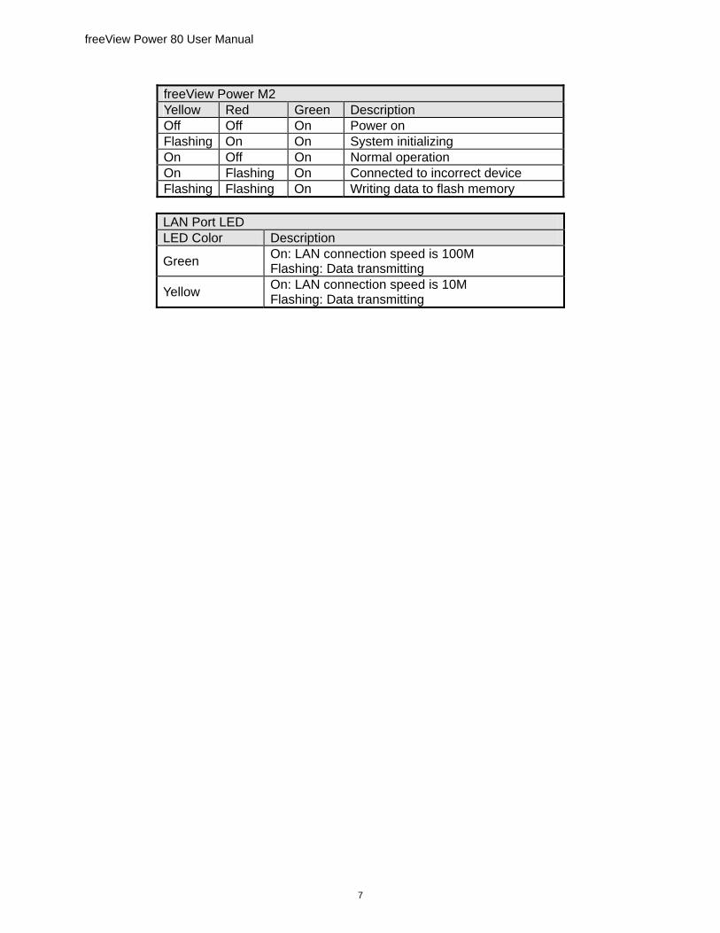
The following tables describe the functions of the LEDs on both modules.
freeView Power M1 LED Color Condition Description Green Power state On: Normal power
Red Connection state with device Flashing: Connected to incorrect device
freeView Power 80 User Manual
7
freeView Power M2 Yellow Red Green Description Off Off On Power on Flashing On On System initializing On Off On Normal operation On Flashing On Connected to incorrect device Flashing Flashing On Writing data to flash memory
LAN Port LED LED Color Description
Green On: LAN connection speed is 100M Flashing: Data transmitting
Yellow On: LAN connection speed is 10M Flashing: Data transmitting
8
3 Daisy Chaining
3.1 Daisy Chaining Up to sixteen units of the freeView Power 80 can be daisy chained to provide up to 128 managed power outlets. Each unit in the chain must be assigned a unique identification number. The default ID is 0. The following procedure explains how to daisy chain multiple units together:
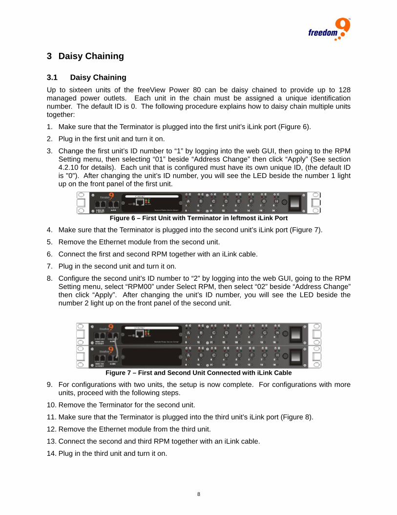
1. Make sure that the Terminator is plugged into the first unit’s iLink port (Figure 6).
2. Plug in the first unit and turn it on.
3. Change the first unit’s ID number to “1” by logging into the web GUI, then going to the RPM Setting menu, then selecting “01” beside “Address Change” then click “Apply” (See section 4.2.10 for details). Each unit that is configured must have its own unique ID, (the default ID is "0"). After changing the unit’s ID number, you will see the LED beside the number 1 light up on the front panel of the first unit.
Figure 6 – First Unit with Terminator in leftmost iLink Port
4. Make sure that the Terminator is plugged into the second unit’s iLink port (Figure 7).
5. Remove the Ethernet module from the second unit.
6. Connect the first and second RPM together with an iLink cable.
7. Plug in the second unit and turn it on.
8. Configure the second unit’s ID number to “2” by logging into the web GUI, going to the RPM Setting menu, select “RPM00” under Select RPM, then select “02” beside “Address Change” then click “Apply”. After changing the unit’s ID number, you will see the LED beside the number 2 light up on the front panel of the second unit.
Figure 7 – First and Second Unit Connected with iLink Cable
9. For configurations with two units, the setup is now complete. For configurations with more units, proceed with the following steps.
10. Remove the Terminator for the second unit.
11. Make sure that the Terminator is plugged into the third unit’s iLink port (Figure 8).
12. Remove the Ethernet module from the third unit.
13. Connect the second and third RPM together with an iLink cable.
14. Plug in the third unit and turn it on.

freeView Power 80 User Manual
9
15. Configure the third unit’s ID number to “3” by logging into the web GUI, going to the RPM Setting menu, select “RPM00” under Select RPM, then select “03” beside “Address Change” then click “Apply”. After changing the unit’s ID number, you will see the LED beside the number 3 light up on the front panel of the third unit.
Figure 8 - First Three Units Connected with iLink Cable
For configurations with more than three units, repeat steps 10-15 for the remaining units.

10
4 Managing the Device
4.1 SNMPIV The included SNMPIV software allows you to perform maintenance on the device even if you do not know the IP address of the unit. The SNMPIV software also includes a standard MIB which allows the unit to be monitored with third-party network management software.
4.1.1 Installing the Software To install the software, follow these steps:
1. Insert the CD included in the box in your CD-ROM drive.
2. Open Windows Explorer and browse to the CD-ROM drive.
3. Double-click on the file “SNMP Utility.exe”.
4. Follow the instructions displayed on the screen to install the software.
5. After completing the installation, the software can be started by going to Start Menu All Programs SNMP Utility SNMP Utility (Figure 9).
Figure 9 – Windows Start Menu
4.1.2 Using the Software The menu is located on the left side of the window. The table on the right side of the window shows all freeView Power 80 devices on the network (Figure 10).
Figure 10 – SNMP Utility
Network Selection When the software first starts, it will prompt you to select the network interface to use. To change the network interface to use, click “Network Selection” to display a list of available network interfaces (Figure 11), and select the one to use. All devices must be on the same network as the computer in order to be detected by the software.

freeView Power 80 User Manual
11
Figure 11 – Network Selection
Network Selection By default, the software will automatically select a network interface card to use (wired or wireless). To change the network interface to use, click “Network Selection” to display a list of available network interfaces (Figure 11), and select the one to use. All devices must be on the same network as the computer in order to be detected by the software.
Configure The “Configure” button allows you to configure a freeView Power 80 unit selected from the list on the right side of the window. The first tab to be displayed is the “IP Address” tab (Figure 12). On this tab, you can set the IP address of the device dynamically using DHCP, given through BOOTP, or statically by manually entering the information in the window.
Figure 12 – IP Address Tab
After setting the IP address of the device, you can access the web interface or telnet interface of the unit from any computer on the same network as the device.
The second tab is the “Advanced” tab (Figure 13). This tab allows you to set a password for accessing the freeView Power 80 device from the SNMPIV software (this does not affect the

12
web or telnet interface passwords). To set a password, enter the password into the “New password” field, and enter it again in the “Confirm password” field, and click “OK”. Remember to keep a record of this password, as it cannot be recovered if lost.
Figure 13 – Advanced Tab
On this tab, you can also set the ports used by the device for HTTP (web) and telnet access. You can also disable web and/or telnet access altogether by unchecking the boxes next to the applicable interface. If you change a port from the default port, you will have to enter the full IP address and port in order to access to the device. For example, if you change the HTTP port from 80 to 81, you must enter “http://192.168.0.5:81” to access the web interface of the device.
Download Firmware
The software offers a convenient method of upgrading the firmware on a device. To upgrade the firmware on a device, select the device from the list, and click “Download Firmware”. In the new window (Figure 14), enter the path and name of the firmware file or click “…” to browse for the file. The file should end in “.bin”. Click “Start”. During the upgrade, the freeView Power 80’s Red and Yellow LED will flash alternately. After the upgrade has been completed, the unit will reboot automatically.
Note: In the event the firmware upgrade is interrupted (e.g. due to a power failure), the unit will revert to the old firmware version. Performing the upgrade again will load the new firmware onto the unit.
Figure 14 – Firmware Download

freeView Power 80 User Manual
13
Refresh Click the “Refresh” button to search the network for freeView Power 80 devices.
4.2 Web Interface To access the web interface of the freeView Power 80, follow these steps:
1. Open a web browser (Internet Explorer 6.0 or higher is recommended).
2. Enter the IP address of the unit into the address bar (e.g. “http://192.168.0.5”)
3. On the login screen, enter the user name and password (Figure 15). By default, both fields are blank. It is recommended that you change the user name and password as soon as possible for security reasons.
Figure 15 – Login Window
4.2.1 Main Menu The main menu consists of four categories (Figure 16).

14
Figure 16 – Main Menu
Information: Provides information for the connected devices.
Configuration: Allows for configuration of the network and devices settings.
Log Information: Displays the log of events that occurred on the device.
Device selection: Not currently used.
Each category consists of different pages which are described in detail in the following sections.

freeView Power 80 User Manual
15
4.2.2 System Status The System Status page (Figure 17) displays the details of the system along with current network configuration settings.
Figure 17 – System Status Page
Firmware Version: Current version of firmware on the unit.
Device Number: Unique identifier for the unit.
System Name: The name given to the unit for identification purposes – used with SNMP.
System Contact: The name of the person to contact in case there are problems with the unit – used with SNMP.
Location: The location of the unit – used with SNMP.
System Time: The local time on the device.
Uptime: The amount of time the unit has been running.
MAC Address: The MAC address of the unit.
The remaining items will be explained in the following sections.
16
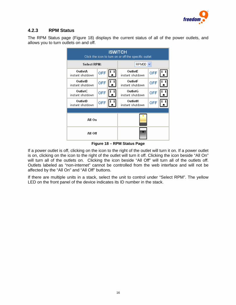
4.2.3 RPM Status The RPM Status page (Figure 18) displays the current status of all of the power outlets, and allows you to turn outlets on and off.
Figure 18 – RPM Status Page
If a power outlet is off, clicking on the icon to the right of the outlet will turn it on. If a power outlet is on, clicking on the icon to the right of the outlet will turn it off. Clicking the icon beside “All On” will turn all of the outlets on. Clicking the icon beside “All Off” will turn all of the outlets off. Outlets labeled as “non-internet” cannot be controlled from the web interface and will not be affected by the “All On” and “All Off” buttons.
If there are multiple units in a stack, select the unit to control under “Select RPM”. The yellow LED on the front panel of the device indicates its ID number in the stack.
freeView Power 80 User Manual
17
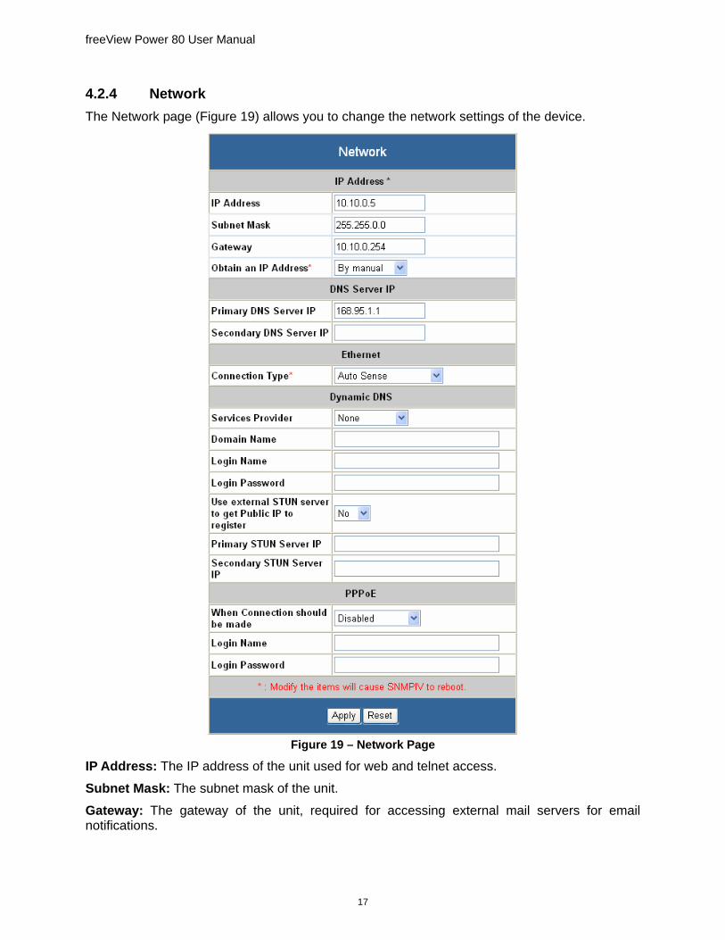
4.2.4 Network The Network page (Figure 19) allows you to change the network settings of the device.
Figure 19 – Network Page
IP Address: The IP address of the unit used for web and telnet access.
Subnet Mask: The subnet mask of the unit.
Gateway: The gateway of the unit, required for accessing external mail servers for email notifications.

18
Obtain an IP Address: Select whether the unit uses the IP address entered manually in the fields above, or obtains an IP address from a DHCP server.
Primary DNS Server: The primary DNS server used for name resolution.
Secondary DNS Server: The backup DNS server used for name resolution in the event the primary DNS server is unavailable.
Connection Type: Determine the connection speed and duplex of the Ethernet port (Auso Sense, 10Mbps Half-Duplex, 10Mbps Full-Duplex, 100Mbps Half-Duplex, 100Mbps Full-Duplex). The recommended settings is “Auto Sense”.
Services Provider: The dynamic DNS service provider used (None, 3322.org, dhs.org, dyndns.org, myddns.com).
Domain Name: Your registered DDNS domain name.
Login Name: The DDNS account login name.
Login Password: The DDNS account login password.
Use External STUN server to get Public IP to register: Set whether a STUN server should be used to retrieve the public IP address of the device.
Primary STUN Server IP: If a STUN server is used, this is the primary IP address of the STUN server.
Secondary STUN Server IP: If a STUN server is used, this is the secondary IP address of the STUN server in the event the primary server is unavailable. When Connection should be made: Determine when the unit should connect to a PPPoE internet connection (Disabled, Connect Always).
Login Name: The login name for the PPPoE account.
Login Password: The login password for the PPPoE account.

freeView Power 80 User Manual
19
4.2.5 SNMP The SNMP page (Figure 20) allows you to manage the SNMP access rights to the device. By default, read/write access is allowed from any computer on the network. It is recommended to change this as soon as possible for security purposes.
Figure 20 – SNMP Page
System Name: The name given to the unit for identification purposes which will be displayed on the SNMP client.
System Contact: The name of the person to contact in case there are problems with the unit which will be displayed on the SNMP client.
Location: The location of the unit which will be displayed on the SNMP client.
Manager IP Address: Restricts access to the unit via SNMP from the specified IP address range. * is used as a wildcard.
Community: The SNMP community name that the device belongs to. Only SNMP clients with

20
the same community name can connect to the device.
Permission: The permissions granted to users connecting using this interface (No Access, Read, Read/Write).
Description: A brief description of the connecting users for the administrator’s reference.
Receiver IP Address: The IP address of the computer that should receive trap events.
Community: The SNMP community name that the device belongs to. Only SNMP clients with the same community name can receive the trap event.
Severity: Set the level of trap events to accept:
• Information: Receive all traps.
• Warning: Receive only “warning” and “severe” traps.
• Severe: Receive only “severe” traps.
Acceptance: Set whether or not to turn the traps on.
Description: A brief description of the trap recipient for the administrator’s reference.
Events: Clicking this button opens up a window where you can select exactly which traps to send (Figure 21). The events listed under “ENV Events” require a freeView Power M2 module to be installed in the device.
Figure 21 – SNMP Events

freeView Power 80 User Manual
21
4.2.6 Email The Email page (Figure 22) allows you to set up email addresses to receive event notifications and daily reports from the freeView Power 80.
Figure 22 – Email Page
Email Server: The SMTP server to use to send out emails.
Sender’s Email Address: The email address to use in the “From” field for outgoing emails.
Email Server Requires Authentication: Set whether the SMTP server requires authentication or not.
Account Name: The account name to log into the SMTP server if required.
Password: The password to log into the SMTP server if required.
Send Email When Event Occurs: Turns on email notifications on system events.
Email Address (Event Log): The email address to send the events to.

22
Events Selection: Clicking this button opens up a window where you can select exactly which traps to send (Figure 21). The events listed under “ENV Events” require a freeView Power M2 module to be installed in the device.
Email Address (Daily Report): The email address to send the daily report to.
Send Email for Daily Report: Set to “YES” to turn on daily report emails and enter a time in hh:mm:ss format for emails to be sent every day.
4.2.7 PPP The PPP Page (Figure 23) allows you to configure modem access for the freeView Power 80. Modem access requires a freeView Power M2 module be installed in the device.
Figure 23 – PPP Page
Login Name: The login name to use when logging into the device through the modem.
Login Password: The login password to use when logging into the device through the modem.
PPP Server IP: The IP address of the PPP server.
Login IP: The IP address used to log in to the device.
Modem Script: The script used to initialize the modem.
freeView Power 80 User Manual
23
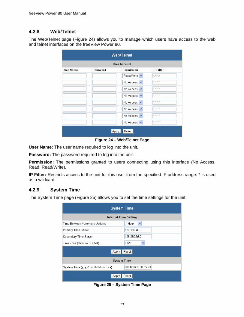
4.2.8 Web/Telnet The Web/Telnet page (Figure 24) allows you to manage which users have access to the web and telnet interfaces on the freeView Power 80.
Figure 24 – Web/Telnet Page
User Name: The user name required to log into the unit.
Password: The password required to log into the unit.
Permission: The permissions granted to users connecting using this interface (No Access, Read, Read/Write).
IP Filter: Restricts access to the unit for this user from the specified IP address range. * is used as a wildcard.
4.2.9 System Time The System Time page (Figure 25) allows you to set the time settings for the unit.
Figure 25 – System Time Page
24
Time Between Automatic Updates: Set the frequency the unit retrieves the current time from the time server (NO, 1 Hour, 3 Hours, 12 Hours, 1 Day, 10 Days, 30 Days).
Primary Time Server: The IP address of the primary NTP server to retrieve the time from.
Secondary Time Server: The IP address of the secondary NTP server to retrieve the time from in the event the primary NTP server is unavailable.
Time Zone: The current time zone relative to GMT.
System Time: To set the time manually, enter it here in “yyyy/mm/dd hh:mm:ss” format.
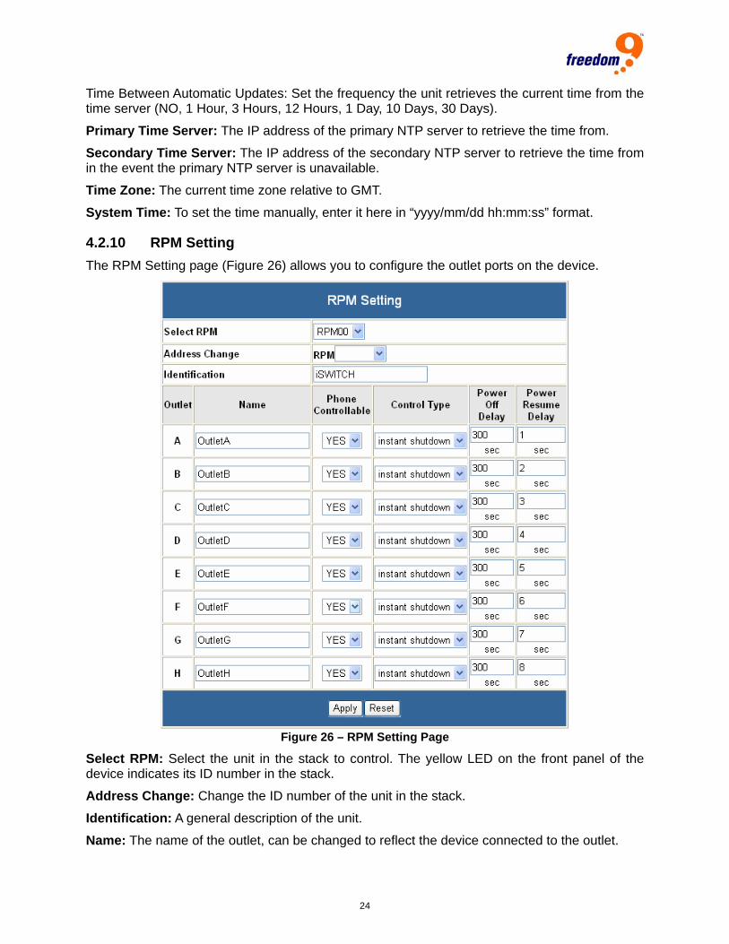
4.2.10 RPM Setting The RPM Setting page (Figure 26) allows you to configure the outlet ports on the device.
Figure 26 – RPM Setting Page
Select RPM: Select the unit in the stack to control. The yellow LED on the front panel of the device indicates its ID number in the stack.
Address Change: Change the ID number of the unit in the stack.
Identification: A general description of the unit.
Name: The name of the outlet, can be changed to reflect the device connected to the outlet.
freeView Power 80 User Manual
25
Phone Controllabe: Set whether the port can be configured through the telephone port.
Control Type: Set the method the freeView Power 80 uses to turn off the outlet.
• Safe shutdown: Turn off the port after the amount of time specified in the Power Off Delay field.
• Safe reboot: Turn off the port after the amount of time specified in the Power Off Delay field. Then turn the port back on after the amount of time specified in the Power Resume Delay field.
• Instant shutdown: Turn off the port immediately.
Power Off Delay: The amount of time to wait before turning the port off in seconds. Applies only when the Control Type is set to Safe Shutdown or Safe Reboot.
Power Resume Delay: The amount of time to wait before turning the port on in seconds. This is used to prevent a surge in power from all devices turning on at the same time. Applies only when the unit initially powers on and if “All On” is selected in the RPM Status page.
When either Safe Shutdown or Safe Reboot is selected, the freeView Power 80 will send a shutdown signal through the RS-232 connectors to the computer attached to the corresponding port as soon as the shutdown command is sent.
To activate support of the shutdown command on the computer, the operating system must be running Windows 2000/XP/2003. To enable safe shutdown, perform the following steps:
1. Go to Control Panel Power Options.
2. Select the UPS tab.
3. Choose to add a UPS then click Select. 4. Choose Generic as the manufacturer.
5. Click Custom under model type, and then select the COM port that the unit is connected to.
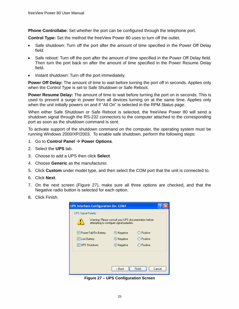
6. Click Next. 7. On the next screen (Figure 27), make sure all three options are checked, and that the
Negative radio button is selected for each option.
8. Click Finish.
Figure 27 – UPS Configuration Screen

26
For more details, refer to the documentation included with your operating system. To allow sufficient time for a graceful system shutdown, it is recommended that the Power Off Delay time be set to at least 120 seconds.
4.2.11 RPM Action The RPM Action page (Figure 28) lists the actions currently defined on the freeView Power 80 and allows you to create new ones or modify and delete existing ones.
Figure 28 – RPM Action Page
The table on the page displays existing actions. An action is taken based on a condition being triggered. The action can be to turn a specific outlet on or off, and the conditions are based on the status of the UPS (currently not available) or of the environment sensor (requires the freeView Power M2 module). The “Edit” button allows you to edit an existing action, and the “Delete” button allows you to delete an existing action. Clicking “New” will open the New RPM Action window (Figure 29) which allows you to create a new action.
Figure 29 – New RPM Action Window
Events Select: Select the condition that will trigger the action.
• UPS Load Overrun: The load on the UPS is too high (currently not used).
• UPS Communication Lost: The connection to the UPS has been lost (currently not used).
• AC Power Failed: The AC power coming into the UPS is unavailable (currently not used).
• UPS Battery Low: The UPS battery is low on power (currently not used).
• Environmental Temperature Overrun: The environment sensor is reporting a temperature level above the maximum allowable temperature level (requires freeView Power M2 module).
• Environmental Temperature Underrun: The environment sensor is reporting a temperature level below the minimum allowable temperature level (requires freeView Power M2 module).

freeView Power 80 User Manual
27
• Environmental Humidity Overrun: The environment sensor is reporting a humidity level above the maximum allowable humidity level (requires freeView Power M2 module).
• Environmental Humidity Underrun: The environment sensor is reporting a humidity level below the minimum allowable humidity level (requires freeView Power M2 module).
Events Action: Set whether the action should be performed when the trigger is activated (Occur) or deactivated (Remove).
RPM: Select the unit in the stack on which to take action.
Outlet: Select the outlet in the unit on which to take action.
Outlet Action: Set whether the outlet should be turned on or off, and if the action should be delayed for a number of seconds.
4.2.12 RPM Schedule The RPM Schedule page (Figure 30) lists the schedules currently defined on the freeView Power 80 and allows you to create new ones or modify and delete existing ones.
Figure 30 – RPM Schedule Page
The table on the page displays existing schedules. A schedule can be set to turn an outlet on or off at a specific time. The “Edit” button allows you to edit an existing action, and the “Delete” button allows you to delete an existing action. Clicking “New” will open the New RPM Schedule window (Figure 31) which allows you to create a new schedule.
Figure 31 – New RPM Schedule Window

28
RPM: Select the unit in the stack on which to take action.
Outlet: Select the outlet in the unit on which to take action.
Outlet Action: Set whether the outlet should be turned on or off.
Date: The date to activate the event. Can be set to a single date in “yyyy/mm/dd” format or occur on a daily or weekly basis.
Time: The time in “hh:mm” format to activate the event.
4.2.13 Save/Restore Settings The Save/Restore Settings page (Figure 32) allows you to back up the system settings to a your local hard drive, restore system settings from a back up file, or reset the device to factory defaults.
Figure 32 – Save/Restore Settings Page
Save current configuration: Click the “Save” button to save a config.bin file to your local hard drive as a back up of the current system configuration. This file can also be uploaded to other freeView Power 80 units to copy the settings to the other unit.
Restore previous configuration: Click “Browse…” and select the config.bin system configuration backup file that was previously saved to your hard drive. Then click the “Restore” button to upload the configuration file.
Reset to factory default: Resets all settings back to the factory defaults.
4.2.14 Event Log The Event Log page (Figure 33) displays the events that have occurred on the unit.

freeView Power 80 User Manual
29
Figure 33 – Event Log Page
The possible events for the freeView Power 80 are:
• RPM Connection Lost: One of the freeView Power 80 units in the stack is unavailable.
• Outlet On: A specific outlet has been turned on.
• Outlet Off: A specific outlet has been turned off.
• Outlet Reboot: A specific outlet has been rebooted.
• Outlet Fault: A specific outlet is defective.
With the freeView Power M2 module, the following events can occur:
• Environmental Temperature Overrun: The environment sensor reported a temperature level above the maximum allowable temperature level.
• Environmental Temperature Underrun: The environment sensor reported a temperature level below the minimum allowable temperature level.
• Environmental Humidity Overrun: The environment sensor reported a humidity level above the maximum allowable humidity level.
• Environmental Humidity Underrun: The environment sensor reported a humidity level below the minimum allowable humidity level.
4.2.15 Save Event Log Clicking on the Save Event Log link will allow you to download the current event log to your computer in comma delimited format.
4.3 Telnet To connect to the freeView Power 80 using Telnet, follow these steps:
1. In Windows, click the Start Menu, then click “Run…” (Figure 34)
2. Type in “telnet <ip address>” where <ip address> is the IP address of the freeView Power 80.

30
Figure 34 – Starting Telnet
3. Once the Telnet connection has been made, the screen shown in Figure 35 will be displayed.
Figure 35 – Telnet Connection
4. Enter the user name and password (Figure 36). The default value for both user name and password is nothing. It is highly recommended that these be changed as quickly as possible for security purposes.
Figure 36 – Logging In
5. The main menu shown in Figure 37 will be displayed.
Figure 37 – Main Menu
The following section provides details on the menu options.
Set IP Address Sets the IP address, Gateway address, and Subnet Mask of the unit.

freeView Power 80 User Manual
31
Set SNMP MIB System Sets the MIB system group parameters.
Set SNMP Access Control Sets the Manager IP, Community, and Access Permissions for SNMP access.
Set SNMP Trap Notification Sets the IP address of computer which will receive the SNMP trap events.
Set UPS Properties Not used at this time.
Set UPS Devices Connected Not used at this time.
Set System Time & Time Server Sets the time, date, and time servers.
Set Web and Telnet User Account Used to manage the users which have access to the device, including user names, passwords, and access levels.
Set E-mail Sets the email settings for log events and notifications.
Reset Configuration to Default Changes all settings back to their default values.
Set Environment Group Not used at this time.
Save & Reboot Saves the settings made during the current session and restarts the device.
Exit Without Saving Exits the Telnet session without saving any of the changes.
4.4 Telephone Access The freeView Power 80 can be managed by connecting the unit to a standard analog telephone line and dialing the telephone number associated with the unit.
Note: Telephone access must be enabled in the web interface for the port that is to be managed via telephone.

32
4.4.1 Logging In To manage the freeView Power 80 using a touch tone telephone, the unit must be connected to a live telephone line.
Dial the phone number of the freeView Power 80.
After three rings, the unit will answer with two short beeps.
Enter your dial-in password followed by the “#” key. (The default password is 123456789)
If the password is correct, you will hear two short beeps. If the password is incorrect, you will hear one long beep.
Once logged in, you can issue instructions to the unit. If you are inactive for 180 seconds, the unit will automatically log you out.
4.4.2 Managing Power Ports Each outlet can be turned on, turned off, and reset using special number combinations representing different instructions. The instructions are either 4 or 8 numbers, and follow the pattern described below.
Instruction format: AABC# or AABCDDDD#
AA – The unique ID of the unit between 00 and 16. Single digit IDs must be entered as two digits (e.g. enter “05” instead of “5”). If there is no daisy chain present, any number is accepted.
B – The power outlet number on the unit (1 through 8). Pressing 9 affects all of the outlets.
C – The action to perform. Available actions are: 0 to turn an outlet off, 1 to turn an outlet on, and 2 to reset an outlet.
DDDD – The delay in minutes before performing the action (this is optional). The longest delay is 9999 minutes, or 166.65 hours.
After entering the command, press the “#” key to perform the action. You can press “*” to cancel the instruction at any time.
Examples:
• 0150# will turn off Outlet 5 on Unit 1
• 1271# will turn on Outlet 7 on Unit 12
• 0022# will reset Outlet 2 on Unit 0
• 03400060# will turn off Outlet 4 on Unit 3 in 60 minutes
• 06210720# will turn on Outlet 2 on Unit 6 in 720 minutes (12 hours)
• 14122880# will reset Outlet 1 on Unit 14 in 2880 minutes (48 hours, or 2 days)
• 0290# will turn off all of the Outlets on Unit 2.
• 0491# will turn on all of the Outlets on Unit 4.
• 1192# will reset all of the Outlets on Unit 11 after 8 seconds.
Enter “000#” to disconnect from the freeView Power 80.

freeView Power 80 User Manual
33
4.4.3 Changing the Password To change the password, follow these steps:
• Enter the command “888#” after logging in.
• You will hear long beeps indicating that the device is ready to change your password.
• Enter a new password using the following pattern: 888XXXXXXXXXX#. The password (XXXXXXXXXX) must be between 7 and 10 numbers. Enter “888” first, and then enter the new password, and press the “#” key when finished.
• You will hear two short beeps confirming the unit received your entry.
• Reenter the password using the same format as above to confirm the password.
• You will hear four short beeps confirming that the password has been changed.
4.4.4 Recovering the Password If you forget the password for the device, follow these steps to reset the password to the default (123456789).
Dial the phone number of the freeView Power 80.
After three rings, the unit will answer with two short beeps.
Press and hold the “A” and “H” buttons on the freeView Power 80 simultaneously within 20 seconds.
When the “A” and “H” LEDs start blinking, release the two buttons.
You will hear four beeps on the telephone, and the password will have been reset to default.
4.4.5 Telephone Pass-through An analog telephone can be connected to the second telephone port on the unit, and can be used as a standard telephone for inbound and outbound calls as long as the freeView Power 80 is not using the line. For inbound calls, the freeView Power 80 will automatically answer the call after three rings.

34
5 Specifications
5.1 Product Specifications freeView Power 80 Programmable Power Outlets 8 Power Output 125V AC; 15A; 50~60 Hz (max) Power Source Input Ports 1 Power Source Input 125V AC; 15A; 50~60 Hz (max) Circuit Breakers 1 Push Switch 10/100 Ethernet Ports 1 RS-485 Chain Out Ports 1 RS-485 Chain In Ports 1 Telephone Ports 2 Power Requirements DC 12V, 2.5A Temperature Range 32°F - 104°F (0°C - 40°C) Humidity 0% - 95% RH Dimensions (W x H x D) 17.3” x 5.7” x 1.8” (440 x 145 x 44.5 mm)