Embed Size (px)
Citation preview
HELMER SCIENTIFIC14400 Bergen BoulevardNoblesville, IN 46060 USA
PH +1.317.773.9073FAX +1.317.773.9082USA and Canada 800.743.5637
0086
ISO 13485:2003 CERTIFIED360139-D/D
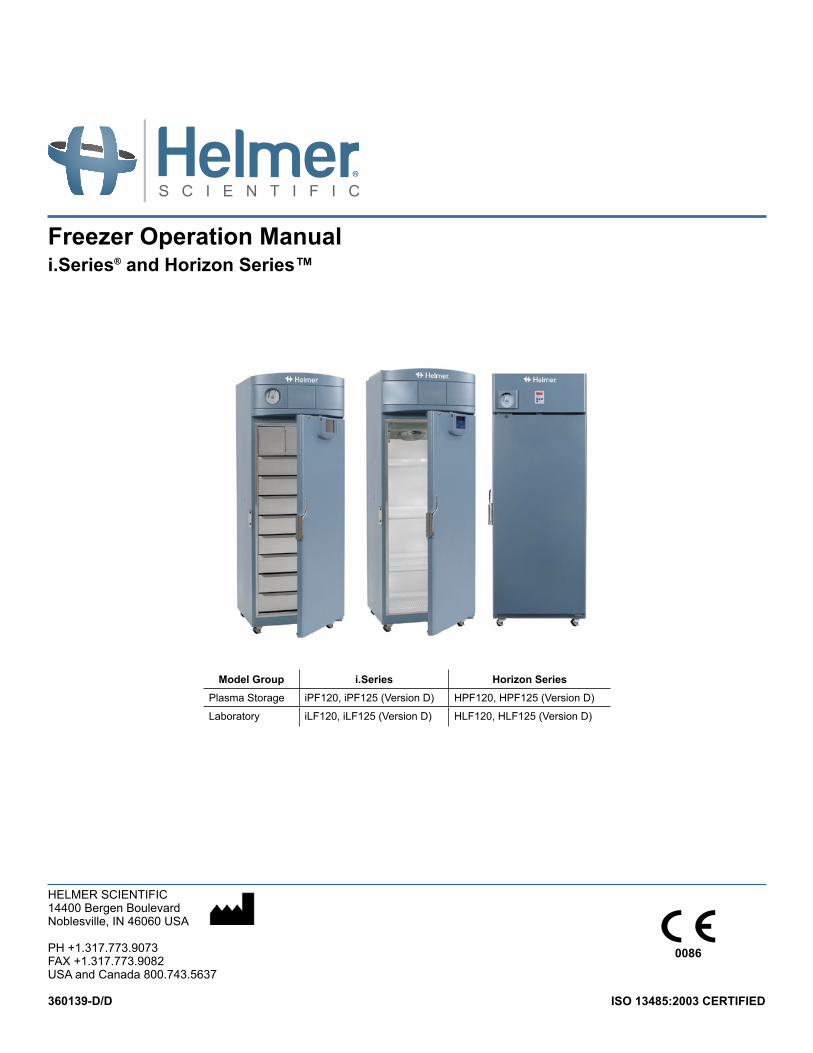
Model Group i.Series Horizon SeriesPlasma Storage iPF120, iPF125 (Version D) HPF120, HPF125 (Version D)
Laboratory iLF120, iLF125 (Version D) HLF120, HLF125 (Version D)
Freezer Operation Manuali.Series® and Horizon Series™
360139-D/D i
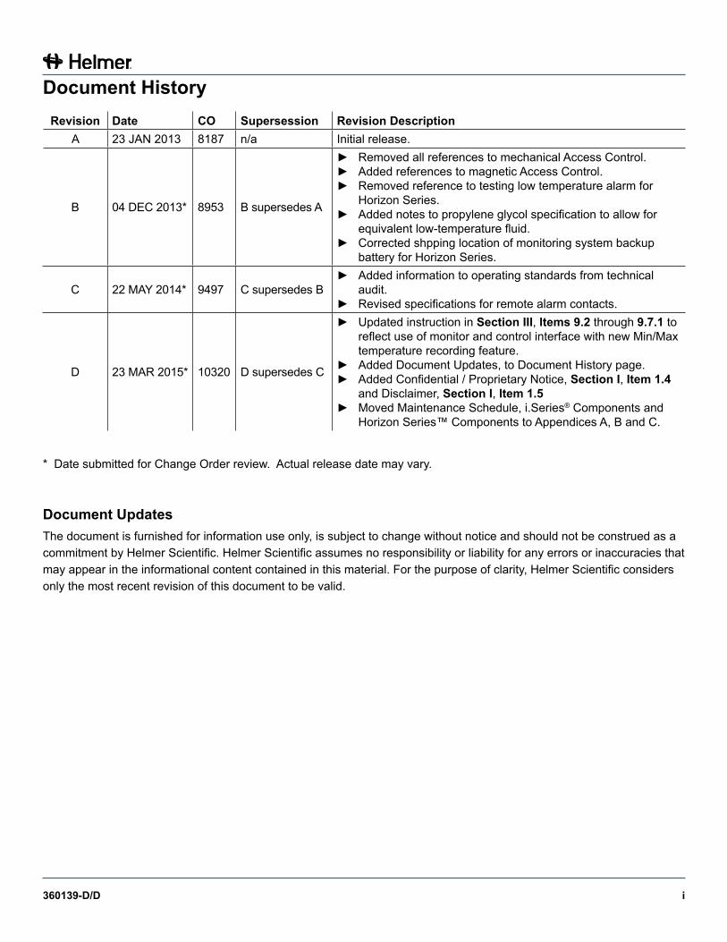
Document HistoryRevision Date CO Supersession Revision Description
A 23 JAN 2013 8187 n/a Initial release.
B 04 DEC 2013* 8953 B supersedes A
► Removed all references to mechanical Access Control.► Added references to magnetic Access Control.► Removed reference to testing low temperature alarm for
Horizon Series.► Added notes to propylene glycol specification to allow for
equivalent low-temperature fluid.► Corrected shpping location of monitoring system backup
battery for Horizon Series.
C 22 MAY 2014* 9497 C supersedes B► Added information to operating standards from technical
audit.► Revised specifications for remote alarm contacts.
D 23 MAR 2015* 10320 D supersedes C
► Updated instruction in Section III, Items 9.2 through 9.7.1 to reflect use of monitor and control interface with new Min/Max temperature recording feature.
► Added Document Updates, to Document History page.► Added Confidential / Proprietary Notice, Section I, Item 1.4
and Disclaimer, Section I, Item 1.5► Moved Maintenance Schedule, i.Series® Components and
Horizon Series™ Components to Appendices A, B and C.
* Date submitted for Change Order review. Actual release date may vary.
Document UpdatesThe document is furnished for information use only, is subject to change without notice and should not be construed as a commitment by Helmer Scientific. Helmer Scientific assumes no responsibility or liability for any errors or inaccuracies that may appear in the informational content contained in this material. For the purpose of clarity, Helmer Scientific considers only the most recent revision of this document to be valid.
360139-D/D ii
Contents
Section I: General Information . . . . . . . . . . . . . . . . . . . . . . . . . . . . . . . . . . . . . . . . 41 About this Manual . . . . . . . . . . . . . . . . . . . . . . . . . . . . . . . . . . . . . . . . . . . . . . . . . . . . . . . . . . 4
1.1 Intended Audience. . . . . . . . . . . . . . . . . . . . . . . . . . . . . . . . . . . . . . . . . . . . . . . . . . . . . . . . . . . . . . . . . . . . . . 41.2 Model References . . . . . . . . . . . . . . . . . . . . . . . . . . . . . . . . . . . . . . . . . . . . . . . . . . . . . . . . . . . . . . . . . . . . . . 41.3 Copyright and Trademark . . . . . . . . . . . . . . . . . . . . . . . . . . . . . . . . . . . . . . . . . . . . . . . . . . . . . . . . . . . . . . . . 41.4 Confidential / Proprietary Notices . . . . . . . . . . . . . . . . . . . . . . . . . . . . . . . . . . . . . . . . . . . . . . . . . . . . . . . . . . 41.5 Disclaimer . . . . . . . . . . . . . . . . . . . . . . . . . . . . . . . . . . . . . . . . . . . . . . . . . . . . . . . . . . . . . . . . . . . . . . . . . . . . 4
2 Safety . . . . . . . . . . . . . . . . . . . . . . . . . . . . . . . . . . . . . . . . . . . . . . . . . . . . . . . . . . . . . . . . . . . . 52.1 Labels . . . . . . . . . . . . . . . . . . . . . . . . . . . . . . . . . . . . . . . . . . . . . . . . . . . . . . . . . . . . . . . . . . . . . . . . . . . . . . . 52.2 Avoiding Injury . . . . . . . . . . . . . . . . . . . . . . . . . . . . . . . . . . . . . . . . . . . . . . . . . . . . . . . . . . . . . . . . . . . . . . . . . 5
3 General Recommendations. . . . . . . . . . . . . . . . . . . . . . . . . . . . . . . . . . . . . . . . . . . . . . . . . . . 53.1 Intended Use . . . . . . . . . . . . . . . . . . . . . . . . . . . . . . . . . . . . . . . . . . . . . . . . . . . . . . . . . . . . . . . . . . . . . . . . . . 53.2 General Use . . . . . . . . . . . . . . . . . . . . . . . . . . . . . . . . . . . . . . . . . . . . . . . . . . . . . . . . . . . . . . . . . . . . . . . . . . 53.3 Initial Loading . . . . . . . . . . . . . . . . . . . . . . . . . . . . . . . . . . . . . . . . . . . . . . . . . . . . . . . . . . . . . . . . . . . . . . . . . 5
4 Operating Standards . . . . . . . . . . . . . . . . . . . . . . . . . . . . . . . . . . . . . . . . . . . . . . . . . . . . . . . . 64.1 Electrical Specifications. . . . . . . . . . . . . . . . . . . . . . . . . . . . . . . . . . . . . . . . . . . . . . . . . . . . . . . . . . . . . . . . . . 64.2 Dimensions . . . . . . . . . . . . . . . . . . . . . . . . . . . . . . . . . . . . . . . . . . . . . . . . . . . . . . . . . . . . . . . . . . . . . . . . . . . 6
4.2.1 Weight . . . . . . . . . . . . . . . . . . . . . . . . . . . . . . . . . . . . . . . . . . . . . . . . . . . . . . . . . . . . . . . . . . . . . . . . 64.2.2 Size . . . . . . . . . . . . . . . . . . . . . . . . . . . . . . . . . . . . . . . . . . . . . . . . . . . . . . . . . . . . . . . . . . . . . . . . . . 7
5 Regulatory Compliance . . . . . . . . . . . . . . . . . . . . . . . . . . . . . . . . . . . . . . . . . . . . . . . . . . . . . . 86 Installation . . . . . . . . . . . . . . . . . . . . . . . . . . . . . . . . . . . . . . . . . . . . . . . . . . . . . . . . . . . . . . . . 8
6.1 Location Requirements . . . . . . . . . . . . . . . . . . . . . . . . . . . . . . . . . . . . . . . . . . . . . . . . . . . . . . . . . . . . . . . . . . 86.1.1 Placement . . . . . . . . . . . . . . . . . . . . . . . . . . . . . . . . . . . . . . . . . . . . . . . . . . . . . . . . . . . . . . . . . . . . . 8
6.2 Temperature Probes . . . . . . . . . . . . . . . . . . . . . . . . . . . . . . . . . . . . . . . . . . . . . . . . . . . . . . . . . . . . . . . . . . . . 96.3 Chart Recorder . . . . . . . . . . . . . . . . . . . . . . . . . . . . . . . . . . . . . . . . . . . . . . . . . . . . . . . . . . . . . . . . . . . . . . . . 9
6.3.1 Install and Change Chart Paper . . . . . . . . . . . . . . . . . . . . . . . . . . . . . . . . . . . . . . . . . . . . . . . . . . . . 10
Section II: i.Series® Models . . . . . . . . . . . . . . . . . . . . . . . . . . . . . . . . . . . . . . . . . . 117 Operation . . . . . . . . . . . . . . . . . . . . . . . . . . . . . . . . . . . . . . . . . . . . . . . . . . . . . . . . . . . . . . . . 11
7.1 Initial Start Up . . . . . . . . . . . . . . . . . . . . . . . . . . . . . . . . . . . . . . . . . . . . . . . . . . . . . . . . . . . . . . . . . . . . . . . . 117.2 Change Temperature Setpoint . . . . . . . . . . . . . . . . . . . . . . . . . . . . . . . . . . . . . . . . . . . . . . . . . . . . . . . . . . . 117.3 Set Alarm Parameters . . . . . . . . . . . . . . . . . . . . . . . . . . . . . . . . . . . . . . . . . . . . . . . . . . . . . . . . . . . . . . . . . . 127.4 Normal Operation . . . . . . . . . . . . . . . . . . . . . . . . . . . . . . . . . . . . . . . . . . . . . . . . . . . . . . . . . . . . . . . . . . . . . 127.5 Active Alarms . . . . . . . . . . . . . . . . . . . . . . . . . . . . . . . . . . . . . . . . . . . . . . . . . . . . . . . . . . . . . . . . . . . . . . . . . 127.6 Mute and Disable Active Alarms . . . . . . . . . . . . . . . . . . . . . . . . . . . . . . . . . . . . . . . . . . . . . . . . . . . . . . . . . . 137.7 Access Control (Optional) . . . . . . . . . . . . . . . . . . . . . . . . . . . . . . . . . . . . . . . . . . . . . . . . . . . . . . . . . . . . . . . 13
7.7.1 Setup . . . . . . . . . . . . . . . . . . . . . . . . . . . . . . . . . . . . . . . . . . . . . . . . . . . . . . . . . . . . . . . . . . . . . . . . 137.7.2 Open Freezer with Access Control . . . . . . . . . . . . . . . . . . . . . . . . . . . . . . . . . . . . . . . . . . . . . . . . . . 14
8 i.C ³® Icon Reference Guide . . . . . . . . . . . . . . . . . . . . . . . . . . . . . . . . . . . . . . . . . . . . . . . . . . 14
Section III: Horizon Series™ Models . . . . . . . . . . . . . . . . . . . . . . . . . . . . . . . . . . 159 Operation . . . . . . . . . . . . . . . . . . . . . . . . . . . . . . . . . . . . . . . . . . . . . . . . . . . . . . . . . . . . . . . . 15
9.1 Initial Start Up . . . . . . . . . . . . . . . . . . . . . . . . . . . . . . . . . . . . . . . . . . . . . . . . . . . . . . . . . . . . . . . . . . . . . . . . 15
360139-D/D iii
9.2 Monitor and Control Interface . . . . . . . . . . . . . . . . . . . . . . . . . . . . . . . . . . . . . . . . . . . . . . . . . . . . . . . . . . . . 159.3 Display Minimum and Maximum Monitor Temperature Recordings . . . . . . . . . . . . . . . . . . . . . . . . . . . . . . . 159.4 Change Freezer Temperature Setpoint . . . . . . . . . . . . . . . . . . . . . . . . . . . . . . . . . . . . . . . . . . . . . . . . . . . . . 169.5 Table of Parameters . . . . . . . . . . . . . . . . . . . . . . . . . . . . . . . . . . . . . . . . . . . . . . . . . . . . . . . . . . . . . . . . . . . 17
9.5.1 Setting Parameter Values . . . . . . . . . . . . . . . . . . . . . . . . . . . . . . . . . . . . . . . . . . . . . . . . . . . . . . . . . 179.5.2 Set Temperature Units . . . . . . . . . . . . . . . . . . . . . . . . . . . . . . . . . . . . . . . . . . . . . . . . . . . . . . . . . . . 17
9.6 Temperature Calibration Offsets . . . . . . . . . . . . . . . . . . . . . . . . . . . . . . . . . . . . . . . . . . . . . . . . . . . . . . . . . . 179.6.1 Monitor Offset . . . . . . . . . . . . . . . . . . . . . . . . . . . . . . . . . . . . . . . . . . . . . . . . . . . . . . . . . . . . . . . . . . 179.6.2 Control Sensor Offset . . . . . . . . . . . . . . . . . . . . . . . . . . . . . . . . . . . . . . . . . . . . . . . . . . . . . . . . . . . . 189.6.3 Hysteresis . . . . . . . . . . . . . . . . . . . . . . . . . . . . . . . . . . . . . . . . . . . . . . . . . . . . . . . . . . . . . . . . . . . . . 18
9.7 Temperature Alarm Setpoints . . . . . . . . . . . . . . . . . . . . . . . . . . . . . . . . . . . . . . . . . . . . . . . . . . . . . . . . . . . . 189.7.1 Change Temperature Alarm Setpoint . . . . . . . . . . . . . . . . . . . . . . . . . . . . . . . . . . . . . . . . . . . . . . . . 18
9.8 Active Alarms . . . . . . . . . . . . . . . . . . . . . . . . . . . . . . . . . . . . . . . . . . . . . . . . . . . . . . . . . . . . . . . . . . . . . . . . . 189.8.1 Mute and Disable Audible Alarms . . . . . . . . . . . . . . . . . . . . . . . . . . . . . . . . . . . . . . . . . . . . . . . . . . . 19
9.9 Access Control (Optional) . . . . . . . . . . . . . . . . . . . . . . . . . . . . . . . . . . . . . . . . . . . . . . . . . . . . . . . . . . . . . . . 199.9.1 Setup . . . . . . . . . . . . . . . . . . . . . . . . . . . . . . . . . . . . . . . . . . . . . . . . . . . . . . . . . . . . . . . . . . . . . . . . 199.9.2 Add User Code . . . . . . . . . . . . . . . . . . . . . . . . . . . . . . . . . . . . . . . . . . . . . . . . . . . . . . . . . . . . . . . . . 199.9.3 Delete User Code . . . . . . . . . . . . . . . . . . . . . . . . . . . . . . . . . . . . . . . . . . . . . . . . . . . . . . . . . . . . . . . 199.9.4 Open Freezer with Access Control . . . . . . . . . . . . . . . . . . . . . . . . . . . . . . . . . . . . . . . . . . . . . . . . . . 19
Appendix A: Maintenance Schedule . . . . . . . . . . . . . . . . . . . . . . . . . . . . . . . . . . 20
Appendix B: i.Series® Components . . . . . . . . . . . . . . . . . . . . . . . . . . . . . . . . . . 21
Appendix C: Horizon Series™ Components . . . . . . . . . . . . . . . . . . . . . . . . . . . 24

360139-D/D 4
General Information
Section I: General Information
1 About this Manual
1.1 Intended AudienceThis manual is intended for use by end users of the freezer and authorized service technicians.
1.2 Model ReferencesGeneric references are used throughout this manual to group models that contain similar features. For example, “125 models” refers to all models of that size (iPF125, HPF125, iLF125, HLF125). This manual covers all upright freezers, which may be identified singly, by their size, or by their respective “Series.”
1.3 Copyright and TrademarkHelmer®, i.Series®, i.C³®, Horizon Series™, and Rel.i™ are registered trademarks or trademarks of Helmer, Inc. in the United States of America. Copyright © 2015 Helmer, Inc. All other trademarks and registered trademarks are the property of their respective owners.
Helmer, Inc., doing business as (DBA) Helmer Scientific and Helmer.
1.4 Confidential/ProprietaryNoticesUse of any portion(s) of this document to copy, translate, disassemble or decompile, or create or attempt to create by reverse engineering or otherwise the information from Helmer Scientific products is expressly prohibited.
1.5 DisclaimerThis manual is intended as a guide to provide the operator with necessary instructions on the proper use and maintenance of certain Helmer Scientific products.
Any failure to follow the instructions as described could result in impaired product function, injury to the operator or others, or void applicable product warranties. Helmer Scientific accepts no responsibility for liability resulting from improper use or maintenance of its products.
The screenshots and component images appearing in this guide are provided for illustrative purposes only, and may vary slightly from the actual software screens and/or product components.
360139-D/D 5
General Information
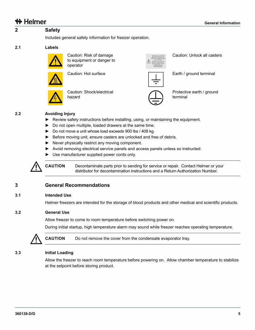
2 SafetyIncludes general safety information for freezer operation.
2.1 Labels
Caution: Risk of damage to equipment or danger to operator
Caution: Unlock all casters
Caution: Hot surface Earth / ground terminal
Caution: Shock/electrical hazard
Protective earth / ground terminal
2.2 Avoiding Injury► Review safety instructions before installing, using, or maintaining the equipment.► Do not open multiple, loaded drawers at the same time.► Do not move a unit whose load exceeds 900 lbs / 408 kg.► Before moving unit, ensure casters are unlocked and free of debris.► Never physically restrict any moving component.► Avoid removing electrical service panels and access panels unless so instructed.► Use manufacturer supplied power cords only.
! CAUTION Decontaminate parts prior to sending for service or repair. Contact Helmer or your distributor for decontamination instructions and a Return Authorization Number.
3 General Recommendations
3.1 Intended UseHelmer freezers are intended for the storage of blood products and other medical and scientific products.
3.2 General UseAllow freezer to come to room temperature before switching power on.
During initial startup, high temperature alarm may sound while freezer reaches operating temperature.
! CAUTION Do not remove the cover from the condensate evaporator tray.
3.3 Initial LoadingAllow the freezer to reach room temperature before powering on. Allow chamber temperature to stabilize at the setpoint before storing product.
360139-D/D 6
General Information
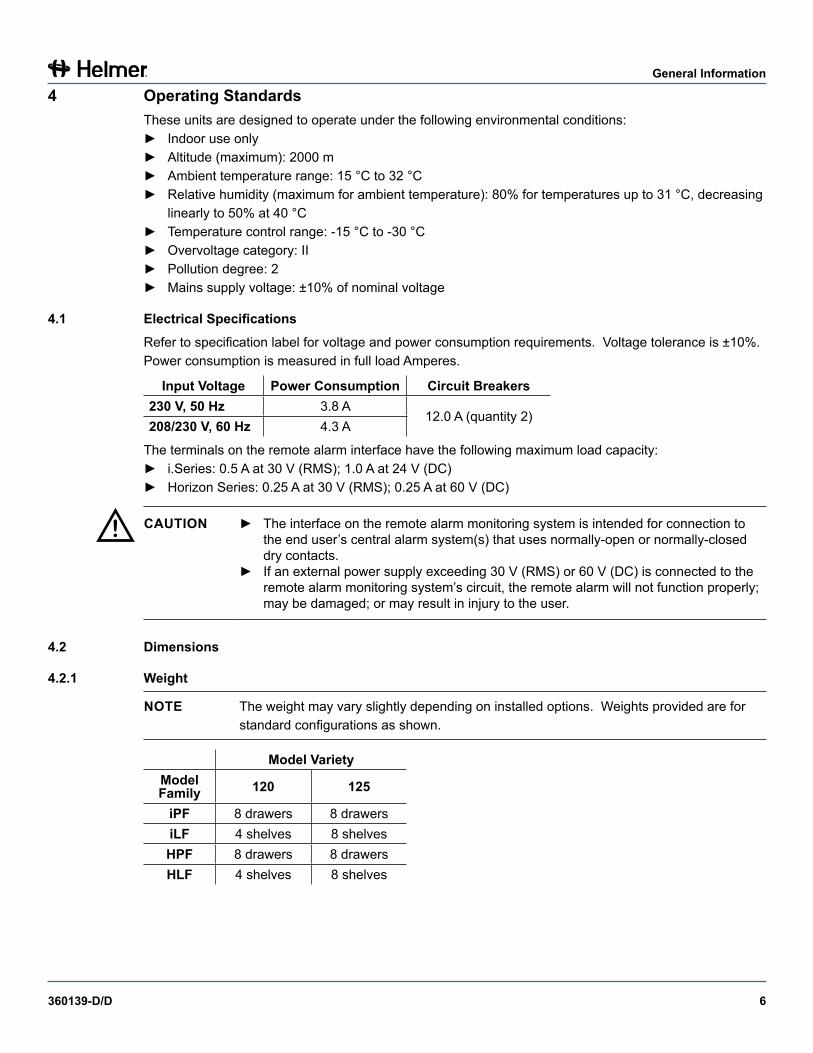
4 Operating StandardsThese units are designed to operate under the following environmental conditions:► Indoor use only► Altitude (maximum): 2000 m► Ambient temperature range: 15 °C to 32 °C► Relative humidity (maximum for ambient temperature): 80% for temperatures up to 31 °C, decreasing
linearly to 50% at 40 °C► Temperature control range: -15 °C to -30 °C► Overvoltage category: II► Pollution degree: 2► Mains supply voltage: ±10% of nominal voltage
4.1 ElectricalSpecificationsRefer to specification label for voltage and power consumption requirements. Voltage tolerance is ±10%. Power consumption is measured in full load Amperes.
Input Voltage PowerConsumption Circuit Breakers230 V, 50 Hz 3.8 A
12.0 A (quantity 2)208/230 V, 60 Hz 4.3 A
The terminals on the remote alarm interface have the following maximum load capacity:► i.Series: 0.5 A at 30 V (RMS); 1.0 A at 24 V (DC)► Horizon Series: 0.25 A at 30 V (RMS); 0.25 A at 60 V (DC)
! CAUTION ► The interface on the remote alarm monitoring system is intended for connection to the end user’s central alarm system(s) that uses normally-open or normally-closed dry contacts.
► If an external power supply exceeding 30 V (RMS) or 60 V (DC) is connected to the remote alarm monitoring system’s circuit, the remote alarm will not function properly; may be damaged; or may result in injury to the user.
4.2 Dimensions
4.2.1 Weight
NOTE The weight may vary slightly depending on installed options. Weights provided are for standard configurations as shown.
Model VarietyModel Family 120 125
iPF 8 drawers 8 drawersiLF 4 shelves 8 shelvesHPF 8 drawers 8 drawersHLF 4 shelves 8 shelves
360139-D/D 7
General Information
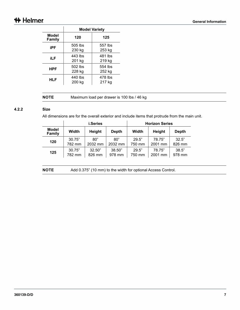
Model VarietyModel Family 120 125
iPF 505 lbs 230 kg
557 lbs 253 kg
iLF 443 lbs 201 kg
481 lbs 219 kg
HPF 502 lbs 228 kg
554 lbs 252 kg
HLF 440 lbs 200 kg
478 lbs 217 kg
NOTE Maximum load per drawer is 100 lbs / 46 kg
4.2.2 SizeAll dimensions are for the overall exterior and include items that protrude from the main unit.
i.Series Horizon SeriesModel Family Width Height Depth Width Height Depth
120 30.75” 782 mm
80” 2032 mm
80” 2032 mm
29.5” 750 mm
78.75” 2001 mm
32.5” 826 mm
125 30.75” 782 mm
32.50” 826 mm
38.50” 978 mm
29.5” 750 mm
78.75” 2001 mm
38.5” 978 mm
NOTE Add 0.375” (10 mm) to the width for optional Access Control.
360139-D/D 8
General Information
5 Regulatory ComplianceThis device complies with the requirements of directive 93/42/EEC concerning Medical Devices, as amended by 2007/47/EC.
0086Sound level is less than 70 dB(A).
EC REPEmergo EuropeMolenstraat 152513 BHThe Hague, Netherlands
WEEE ComplianceThe WEEE (waste electrical and electronic equipment) symbol (right) indicates compliance with European Union Directive WEEE 2002/96/EC and applicable provisions. The directive sets requirements for the labeling and disposal of certain products in affected countries.
When disposing of this product in countries affected by this directive:► Do not dispose of this product as unsorted municipal waste.► Collect this product separately.► Use the collection and return systems available locally.
For more information on the return, recovery, or recycling of this product, contact your local distributor.
6 Installation
6.1 Location Requirements► Has a grounded outlet meeting the electrical requirements listed on the product specification label.► Is clear of direct sunlight, high temperature sources, and heating and air conditioning vents.► Minimum 8” (203 mm) above, and minimum 3” (76 mm) behind.► Meets limits specified for ambient temperature and relative humidity.
6.1.1 Placement
! CAUTION ► Do not use the water evaporation tray, located on the rear of the freezer, as a handle. The tray may be hot.
► To prevent tipping, ensure the casters are unlocked, leveling feet (if installed) are lifted, and the doors are closed before moving the freezer.
1 Ensure all casters are unlocked and doors are closed.2 Roll freezer into place and lock casters.3 Ensure freezer is level.
NOTE Helmer recommends the use of leveling feet.
360139-D/D 9
General Information
6.2 TemperatureProbesFor each probe bottle, use:► 4 oz. (120 mL) of product simulation solution (1:1 ratio of water to propylene glycol or equivalent low-
temperature fluid).
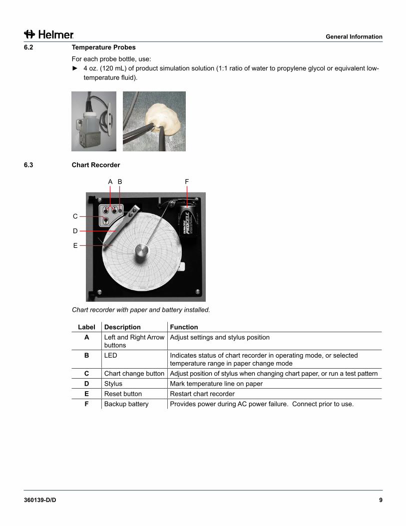
6.3 Chart Recorder
A B F
C
D
E
Chart recorder with paper and battery installed.
Label Description FunctionA Left and Right Arrow
buttonsAdjust settings and stylus position
B LED Indicates status of chart recorder in operating mode, or selected temperature range in paper change mode
C Chart change button Adjust position of stylus when changing chart paper, or run a test patternD Stylus Mark temperature line on paperE Reset button Restart chart recorderF Backup battery Provides power during AC power failure. Connect prior to use.
360139-D/D 10
General Information
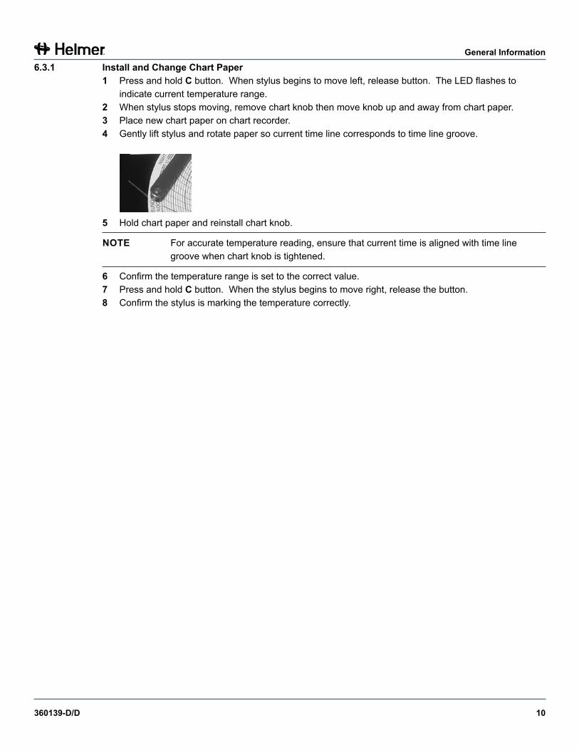
6.3.1 InstallandChangeChartPaper1 Press and hold C button. When stylus begins to move left, release button. The LED flashes to
indicate current temperature range.2 When stylus stops moving, remove chart knob then move knob up and away from chart paper.3 Place new chart paper on chart recorder.4 Gently lift stylus and rotate paper so current time line corresponds to time line groove.
5 Hold chart paper and reinstall chart knob.
NOTE For accurate temperature reading, ensure that current time is aligned with time line groove when chart knob is tightened.
6 Confirm the temperature range is set to the correct value.7 Press and hold C button. When the stylus begins to move right, release the button.8 Confirm the stylus is marking the temperature correctly.
360139-D/D 11
i.Series® Models
Section II: i.Series® Models
7 Operation
7.1 Initial Start Up1 Plug the power cord into a grounded outlet that meets the electrical requirements on the product
specification label.2 Switch AC ON/OFF switch ON.3 Switch backup battery switch ON.
NOTE ► For models equipped with the optional Access Control, the backup battery is switched on with a key switch.
► The i.C³ monitoring and control system will take approximately two minutes to boot up.
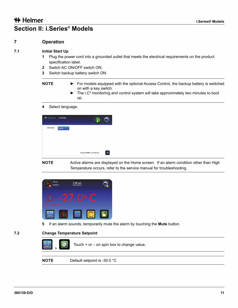
4 Select language.
NOTE Active alarms are displayed on the Home screen. If an alarm condition other than High Temperature occurs, refer to the service manual for troubleshooting.
5 If an alarm sounds, temporarily mute the alarm by touching the Mute button.
7.2 Change Temperature Setpoint
> Touch + or – on spin box to change value.
NOTE Default setpoint is -30.0 °C
360139-D/D 12
i.Series® Models
7.3 SetAlarmParameters
> > Alarm Settings
Control the conditions and timing of alarm condition indicators displayed on the i.C³ Home screen. Touch + or – on spin box to set each parameter.
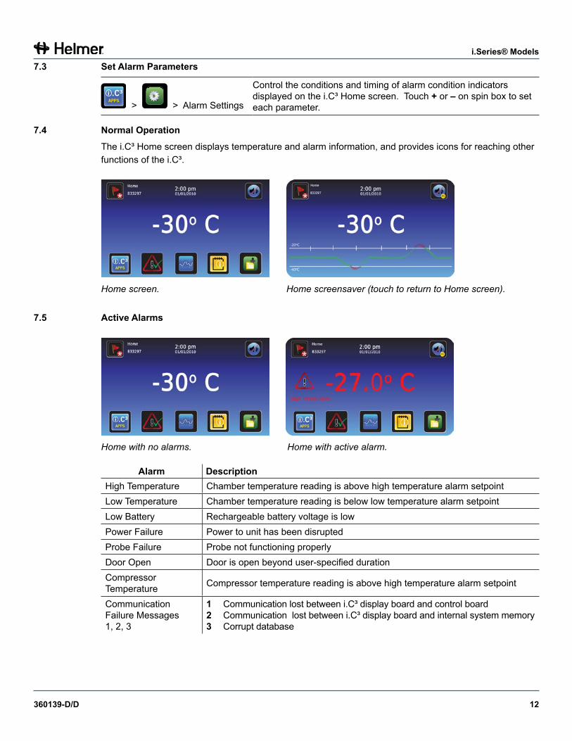
7.4 NormalOperationThe i.C³ Home screen displays temperature and alarm information, and provides icons for reaching other functions of the i.C³.
Home screen. Home screensaver (touch to return to Home screen).
7.5 Active Alarms
Home with no alarms. Home with active alarm.
Alarm DescriptionHigh Temperature Chamber temperature reading is above high temperature alarm setpointLow Temperature Chamber temperature reading is below low temperature alarm setpointLow Battery Rechargeable battery voltage is lowPower Failure Power to unit has been disruptedProbe Failure Probe not functioning properlyDoor Open Door is open beyond user-specified durationCompressor Temperature Compressor temperature reading is above high temperature alarm setpoint
Communication Failure Messages 1, 2, 3
1 Communication lost between i.C³ display board and control board2 Communication lost between i.C³ display board and internal system memory3 Corrupt database
360139-D/D 13
i.Series® Models
7.6 Mute and Disable Active AlarmsAudible alarms may be muted by touching the Mute button to set delay.
:15
Unmuted Muted
7.7 Access Control (Optional)Allows user-specific secure access to the freezer.
NOTE ► During a power failure, the optional Access Control lock will remain locked until battery power is depleted or until the backup battery key switch is switched OFF.
► Switching the backup battery key switch OFF will disable the monitoring system.► During a power failure, switch the battery backup switch OFF and use the mechanical
door key to provide secure storage for freezer contents.
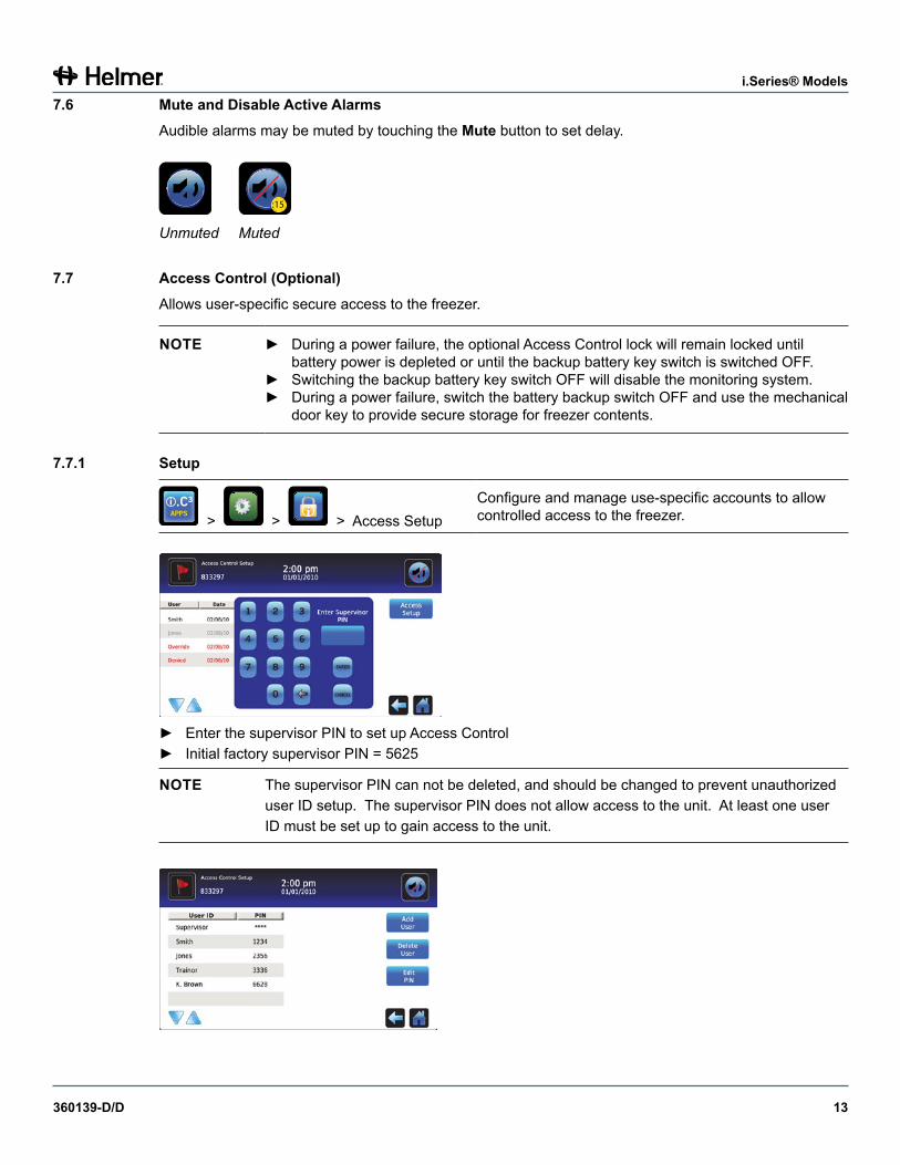
7.7.1 Setup
> > > Access SetupConfigure and manage use-specific accounts to allow controlled access to the freezer.
► Enter the supervisor PIN to set up Access Control► Initial factory supervisor PIN = 5625
NOTE The supervisor PIN can not be deleted, and should be changed to prevent unauthorized user ID setup. The supervisor PIN does not allow access to the unit. At least one user ID must be set up to gain access to the unit.
360139-D/D 14
i.Series® Models
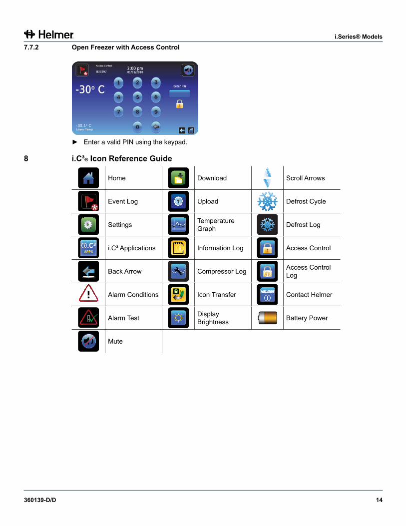
7.7.2 OpenFreezerwithAccessControl
► Enter a valid PIN using the keypad.
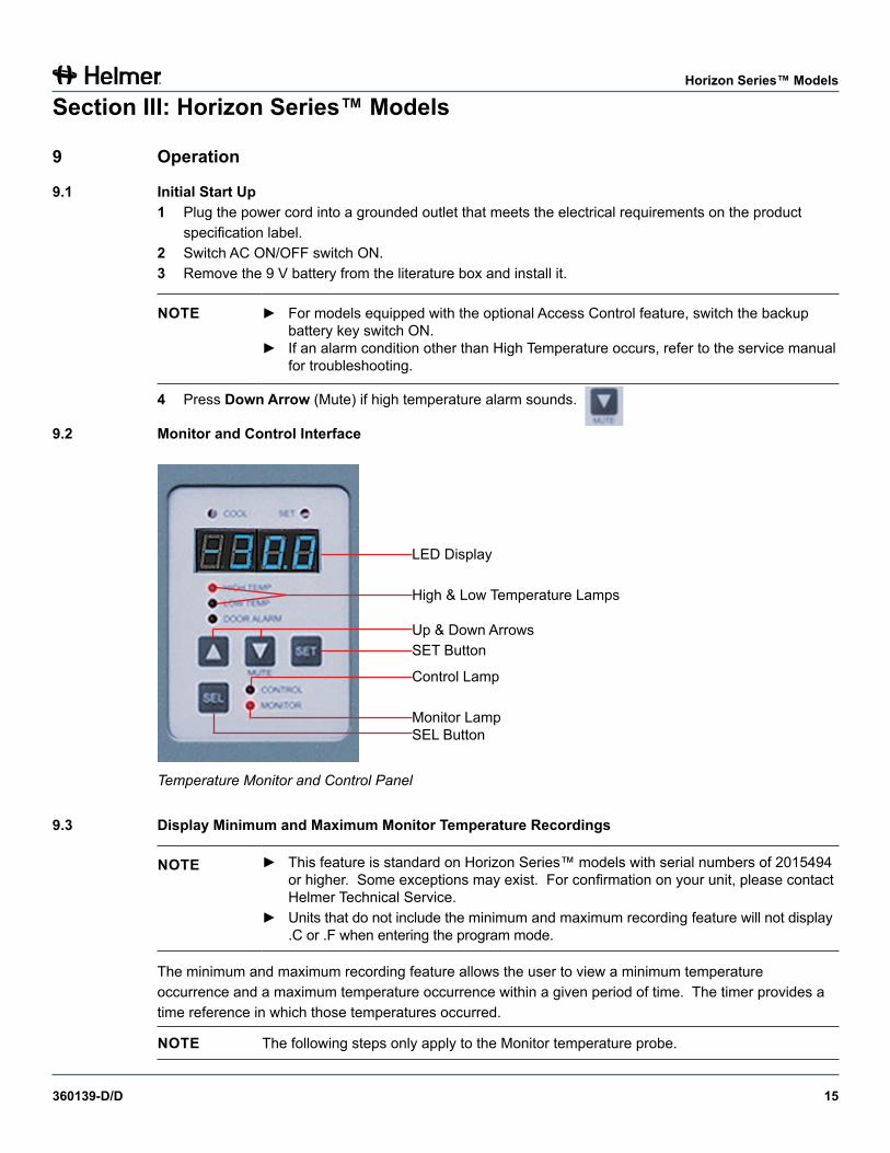
8 i.C ³® Icon Reference Guide
Home Download Scroll Arrows
Event Log Upload Defrost Cycle
Settings Temperature Graph Defrost Log
i.C³ Applications Information Log Access Control
Back Arrow Compressor Log Access Control Log
Alarm Conditions Icon Transfer Contact Helmer
Alarm Test Display Brightness Battery Power
Mute
360139-D/D 15
Horizon Series™ Models
Section III: Horizon Series™ Models
9 Operation
9.1 Initial Start Up1 Plug the power cord into a grounded outlet that meets the electrical requirements on the product
specification label.2 Switch AC ON/OFF switch ON.3 Remove the 9 V battery from the literature box and install it.
NOTE ► For models equipped with the optional Access Control feature, switch the backup battery key switch ON.
► If an alarm condition other than High Temperature occurs, refer to the service manual for troubleshooting.
4 Press DownArrow (Mute) if high temperature alarm sounds.
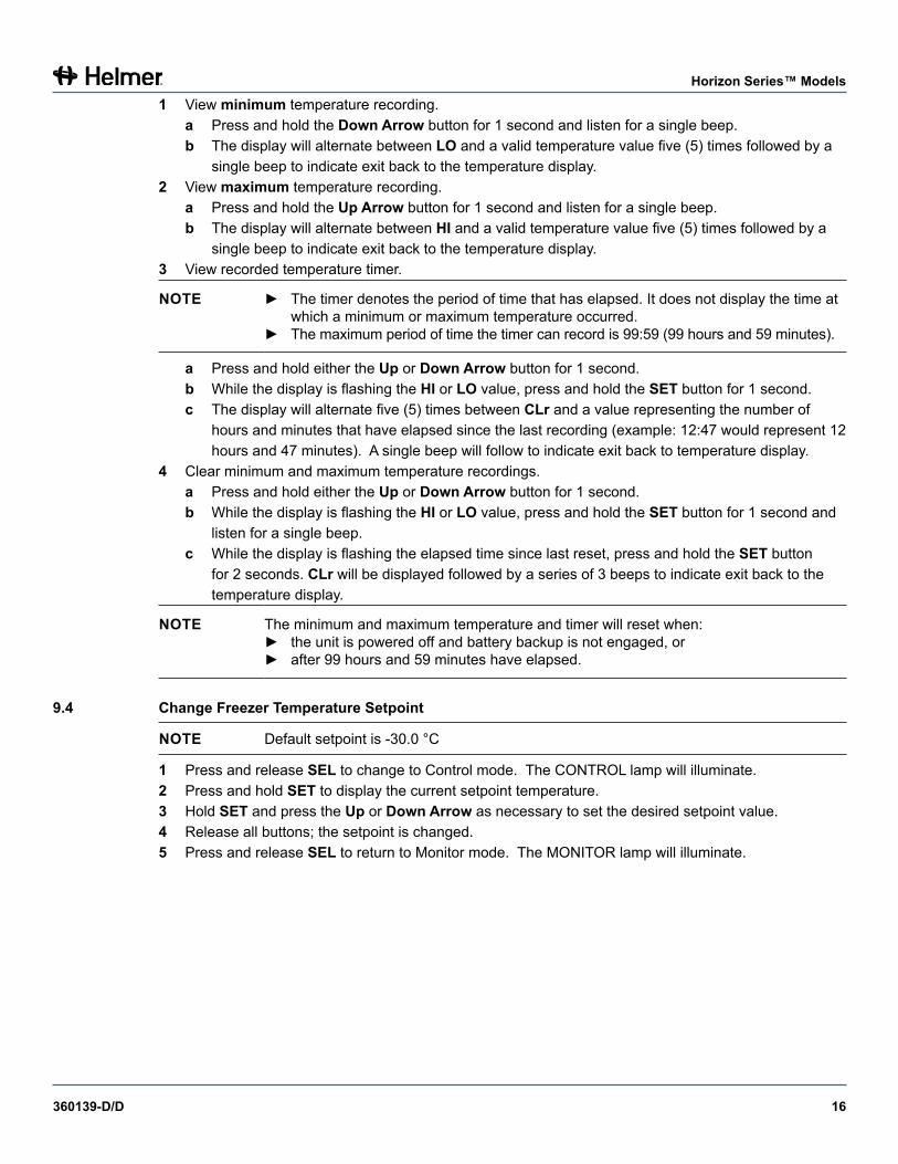
9.2 Monitor and Control Interface
Temperature Monitor and Control Panel
9.3 Display Minimum and Maximum Monitor Temperature Recordings
NOTE ► This feature is standard on Horizon Series™ models with serial numbers of 2015494 or higher. Some exceptions may exist. For confirmation on your unit, please contact Helmer Technical Service.
► Units that do not include the minimum and maximum recording feature will not display .C or .F when entering the program mode.
The minimum and maximum recording feature allows the user to view a minimum temperature occurrence and a maximum temperature occurrence within a given period of time. The timer provides a time reference in which those temperatures occurred.
NOTE The following steps only apply to the Monitor temperature probe.
LED Display
High & Low Temperature Lamps
Up & Down ArrowsSET Button
Control Lamp
Monitor LampSEL Button
360139-D/D 16
Horizon Series™ Models
1 View minimum temperature recording.a Press and hold the DownArrow button for 1 second and listen for a single beep.b The display will alternate between LO and a valid temperature value five (5) times followed by a
single beep to indicate exit back to the temperature display. 2 View maximum temperature recording.
a Press and hold the UpArrow button for 1 second and listen for a single beep.b The display will alternate between HI and a valid temperature value five (5) times followed by a
single beep to indicate exit back to the temperature display.3 View recorded temperature timer.
NOTE ► The timer denotes the period of time that has elapsed. It does not display the time at which a minimum or maximum temperature occurred.
► The maximum period of time the timer can record is 99:59 (99 hours and 59 minutes).
a Press and hold either the Up or DownArrow button for 1 second.b While the display is flashing the HI or LO value, press and hold the SET button for 1 second.c The display will alternate five (5) times between CLr and a value representing the number of
hours and minutes that have elapsed since the last recording (example: 12:47 would represent 12 hours and 47 minutes). A single beep will follow to indicate exit back to temperature display.
4 Clear minimum and maximum temperature recordings.a Press and hold either the Up or DownArrow button for 1 second.b While the display is flashing the HI or LO value, press and hold the SET button for 1 second and
listen for a single beep.c While the display is flashing the elapsed time since last reset, press and hold the SET button
for 2 seconds. CLr will be displayed followed by a series of 3 beeps to indicate exit back to the temperature display.
NOTE The minimum and maximum temperature and timer will reset when:► the unit is powered off and battery backup is not engaged, or► after 99 hours and 59 minutes have elapsed.
9.4 Change Freezer Temperature Setpoint
NOTE Default setpoint is -30.0 °C
1 Press and release SEL to change to Control mode. The CONTROL lamp will illuminate.2 Press and hold SET to display the current setpoint temperature.3 Hold SET and press the Up or DownArrow as necessary to set the desired setpoint value.4 Release all buttons; the setpoint is changed.5 Press and release SEL to return to Monitor mode. The MONITOR lamp will illuminate.
360139-D/D 17
Horizon Series™ Models
9.5 TableofParameters
Parameter Visual Indicator Range DefaultCelsius or Fahrenheit None .C, .F .CHigh Temperature MONITOR Lamp &
HIGH Lamp-40.0 to 40.0 (°C) -40 to 104 (°F)
-20.0°C
Low Temperature MONITOR Lamp & LOW Lamp
-40.0 to 40.0 (°C) -40 to 104 (°F)
-40.0°C
Monitor Offset MONITOR Lamp -10.0 to 10.0 (°C) -18 to 18 (°F)
Varies
Control Offset CONTROL Lamp -10.0 to 10.0 (°C) -18 to 18 (°F)
Varies
Hysteresis CONTROL Lamp 0.5 to 2.5 (°C) 1 to 5 (°F)
2.0°C
9.5.1 SettingParameterValues1 Press and hold the Up and DownArrows simultaneously for 3 seconds to enter program mode. 2 The LED Display will show .C or .F to indicate Celsius or Fahrenheit.3 Press and release SEL button to scroll through the parameters.4 Once the desired parameter is selected, press and hold the SET button while pressing the Up or
DownArrow to select the desired value.5 Release SET button. The new setting is saved.6 Press and hold the Up and DownArrows simultaneously for 3 seconds to exit program mode.
NOTE Contact Helmer Technical Service for setting Hysteresis values.
9.5.2 Set Temperature Units
NOTE If temperature units are changed, the temperature setpoints, offsets and alarm settings must be recalibrated.
1 Press and hold the Up and DownArrows simultaneously for 3 seconds to enter program mode.2 The LED Display will show .C or .F to indicate Celsius or Fahrenheit.3 Press and hold the SET button while pressing the Up or DownArrow to select the desired
temperature unit.4 Release SET button. The new setting is saved.5 Press and hold the Up and DownArrows simultaneously for 3 seconds to exit program mode.
9.6 Temperature Calibration OffsetsTemperature calibration offsets indicate an acceptable margin of error between the actual temperature value and the desired temperature value.
9.6.1 Monitor Offset► Adjust if temperature displayed on the monitor does not match measured chamber temperature.► Value is factory-set to match a calibrated reference thermometer.► Refer to the service manual for instructions in changing the Monitor Offset.
360139-D/D 18
Horizon Series™ Models
9.6.2 Control Sensor Offset► Value is factory-set to match a calibrated reference thermometer.► Varies for each freezer.
NOTICE Control Sensor Offset is factory-preset and should not be changed. Contact Helmer Technical Service for instructions regarding changing the Control Sensor Offset.
9.6.3 Hysteresis► Allowable temperature variance on each side of the freezer setpoint.
NOTICE Hysteresis is factory-preset and should not be changed. Contact Helmer Technical Service for instructions regarding changing the Hysteresis value.
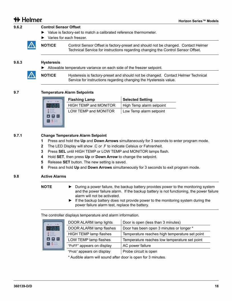
9.7 Temperature Alarm Setpoints
Flashing Lamp Selected SettingHIGH TEMP and MONITOR High Temp alarm setpointLOW TEMP and MONITOR Low Temp alarm setpoint
9.7.1 Change Temperature Alarm Setpoint1 Press and hold the Up and DownArrows simultaneously for 3 seconds to enter program mode.2 The LED Display will show .C or .F to indicate Celsius or Fahrenheit.3 Press SEL until HIGH TEMP or LOW TEMP and MONITOR lamps flash.4 Hold SET, then press Up or DownArrow to change the setpoint.5 Release SET button. The new setting is saved.6 Press and hold Up and DownArrows simultaneously for 3 seconds to exit program mode.
9.8 Active Alarms
NOTE ► During a power failure, the backup battery provides power to the monitoring system and the power failure alarm. If the backup battery is not functioning, the power failure alarm will not be activated.
► If the backup battery does not provide power to the monitoring system during the power failure alarm test, replace the battery.
The controller displays temperature and alarm information.
DOOR ALARM lamp lights Door is open (less than 3 minutes)DOOR ALARM lamp flashes Door has been open 3 minutes or longer *HIGH TEMP lamp flashes Temperature reaches high temperature set pointLOW TEMP lamp flashes Temperature reaches low temperature set point“PoFF” appears on display AC power failure“Prob” appears on display Probe circuit is open* Audible alarm will sound after door is open for 3 minutes.
360139-D/D 19
Horizon Series™ Models
9.8.1 Mute and Disable Audible Alarms► Muting audible alarms does not disable alarm lamps or signals sent through the remote alarm interface.► Press DownArrow (Mute) to mute audible alarms.► To disable all audible alarms, insert the key in the Alarm Disable switch and turn.
9.9 Access Control (Optional)Allows user-specific secure access to the freezer.
NOTE ► During a power failure, the backup battery continues to provide power to the optional Access Control lock (if equipped). If the backup battery is not functioning, the optional Access Control lock will not secure the door.
► During a power failure, the optional Access Control lock will remain locked until battery power is depleted or until the backup battery key switch is switched OFF.
► During an extended power failure, switch the battery backup switch OFF and use the mechanical door key to provide secure storage for freezer contents.
9.9.1 SetupThe Access Control keypad was programmed at the factory with a master code (0000). The master code is used to program the keypad and enter user codes. The master code also releases the door lock.
NOTE The master code cannot be deleted, and should be changed to prevent unauthorized user code setup.
Enter unique user codes for up to 100 users. Each user code is stored with a specific record location number. Keep a log of the location numbers and user codes with users’ names.
9.9.2 Add User Code► Enter the master code► Press 1 to initiate user code programming function► Enter the location number (00 - 99)► Enter the user code (4 - 9 digit number)► Press * to save changes and return to normal operation
9.9.3 Delete User Code► Enter the master code► Press 1 to initiate user code programming function► Enter the location number (00 - 99)► Press * to save changes
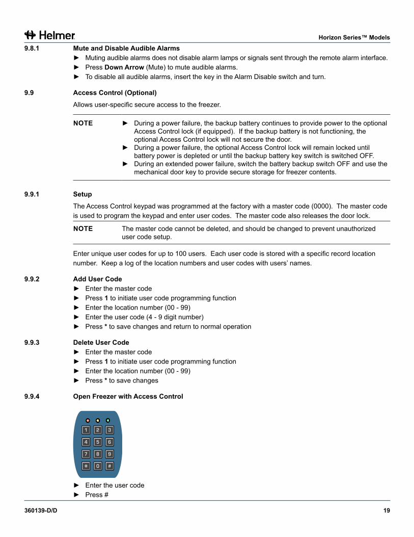
9.9.4 OpenFreezerwithAccessControl
321
654
987
#0
► Enter the user code► Press #
360139-D/D 20
Appendix A
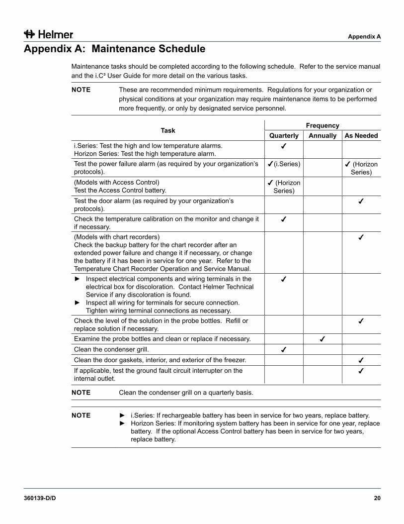
Appendix A: Maintenance ScheduleMaintenance tasks should be completed according to the following schedule. Refer to the service manual and the i.C³ User Guide for more detail on the various tasks.
NOTE These are recommended minimum requirements. Regulations for your organization or physical conditions at your organization may require maintenance items to be performed more frequently, or only by designated service personnel.
TaskFrequency
Quarterly Annually AsNeededi.Series: Test the high and low temperature alarms.Horizon Series: Test the high temperature alarm.
Test the power failure alarm (as required by your organization’s protocols).
(i.Series) (Horizon Series)
(Models with Access Control)Test the Access Control battery.
(Horizon Series)
Test the door alarm (as required by your organization’s protocols).
Check the temperature calibration on the monitor and change it if necessary.
(Models with chart recorders)Check the backup battery for the chart recorder after an extended power failure and change it if necessary, or change the battery if it has been in service for one year. Refer to the Temperature Chart Recorder Operation and Service Manual.
► Inspect electrical components and wiring terminals in the electrical box for discoloration. Contact Helmer Technical Service if any discoloration is found.
► Inspect all wiring for terminals for secure connection. Tighten wiring terminal connections as necessary.
Check the level of the solution in the probe bottles. Refill or replace solution if necessary.
Examine the probe bottles and clean or replace if necessary.
Clean the condenser grill.
Clean the door gaskets, interior, and exterior of the freezer.
If applicable, test the ground fault circuit interrupter on the internal outlet.
NOTE Clean the condenser grill on a quarterly basis.
NOTE ► i.Series: If rechargeable battery has been in service for two years, replace battery.► Horizon Series: If monitoring system battery has been in service for one year, replace
battery. If the optional Access Control battery has been in service for two years, replace battery.

360139-D/D 21
Appendix B
Appendix B: i.Series® Components
Front and Chamber
A
B
CD
E
F
GH
I
J
KL
M
Chamber and front features (iPF120 model shown).
Label DescriptionA Chart recorder (standard on plasma storage models, optional on
laboratory models)B Door lockC i.C³ controlD USB portE Door handle with lockF CasterG ShelfH Standard for adjusting storage componentsI Roll out basketJ Unit cooler with fan guardK Upper probe bottleL Cold-Shield door (plasma storage models with eight drawers)M Drawer
Not shown
Drawer/basket slideLower probe bottle
360139-D/D 22
Appendix B
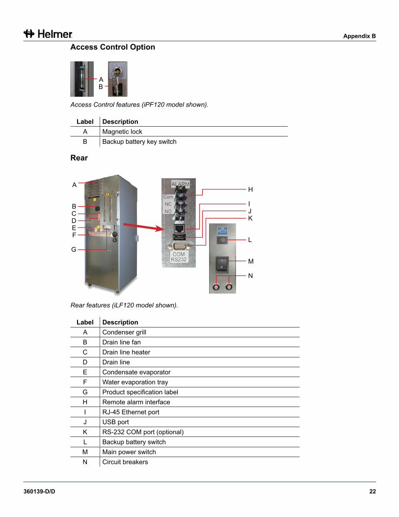
Access Control Option
AB
Access Control features (iPF120 model shown).
Label DescriptionA Magnetic lockB Backup battery key switch
Rear
H
IJK
L
M
N
A
BCDEF
G
Rear features (iLF120 model shown).
Label DescriptionA Condenser grillB Drain line fanC Drain line heaterD Drain lineE Condensate evaporatorF Water evaporation trayG Product specification labelH Remote alarm interfaceI RJ-45 Ethernet portJ USB portK RS-232 COM port (optional)L Backup battery switchM Main power switchN Circuit breakers
360139-D/D 23
Appendix B
Top
A B C D
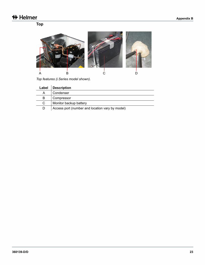
Top features (i.Series model shown).
Label DescriptionA CondenserB CompressorC Monitor backup batteryD Access port (number and location vary by model)
360139-D/D 24
Appendix C
Appendix C: Horizon Series™ Components
Front and Chamber
A
BC
D
E
F
GH
I
J
KL
M
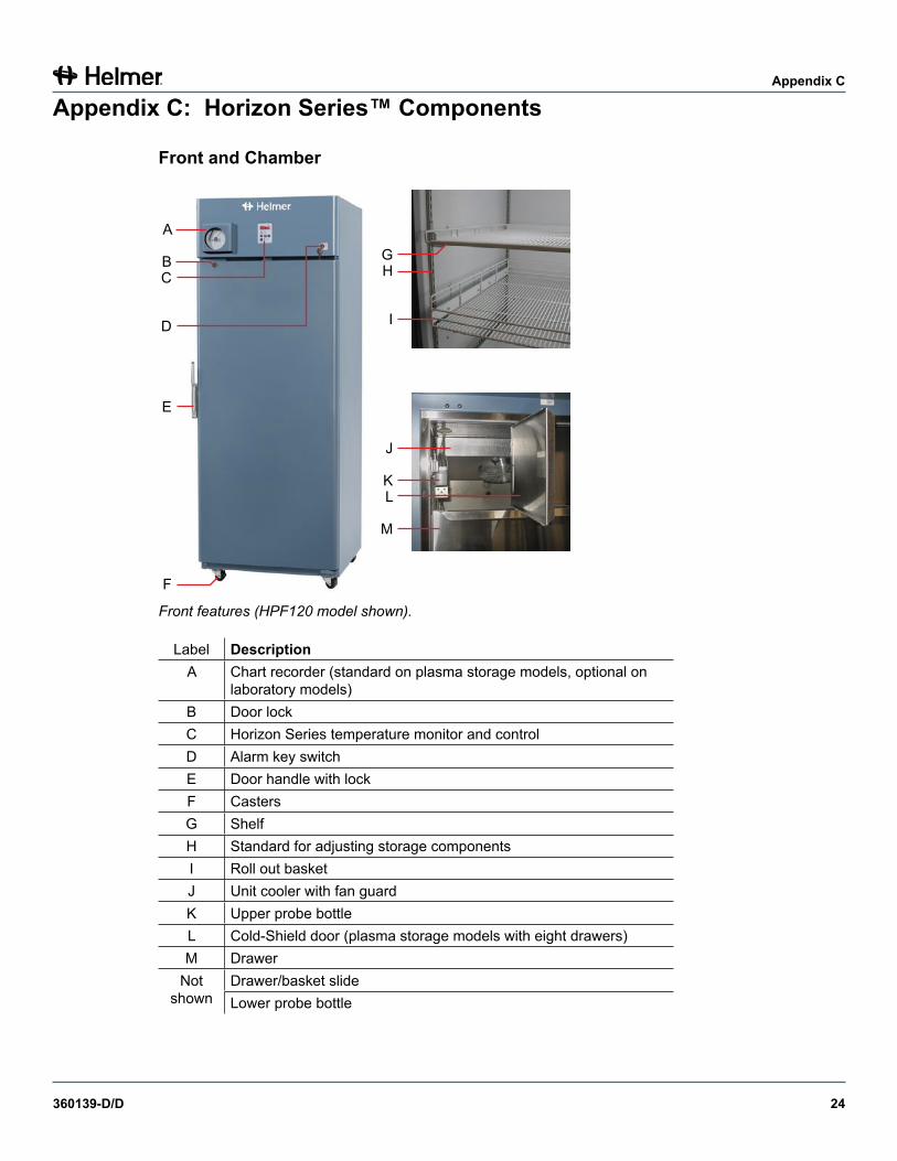
Front features (HPF120 model shown).
Label DescriptionA Chart recorder (standard on plasma storage models, optional on
laboratory models)B Door lockC Horizon Series temperature monitor and controlD Alarm key switchE Door handle with lockF CastersG ShelfH Standard for adjusting storage componentsI Roll out basketJ Unit cooler with fan guardK Upper probe bottleL Cold-Shield door (plasma storage models with eight drawers)M Drawer
Not shown
Drawer/basket slideLower probe bottle
360139-D/D 25
Appendix C
Access Control Option
AB
CD
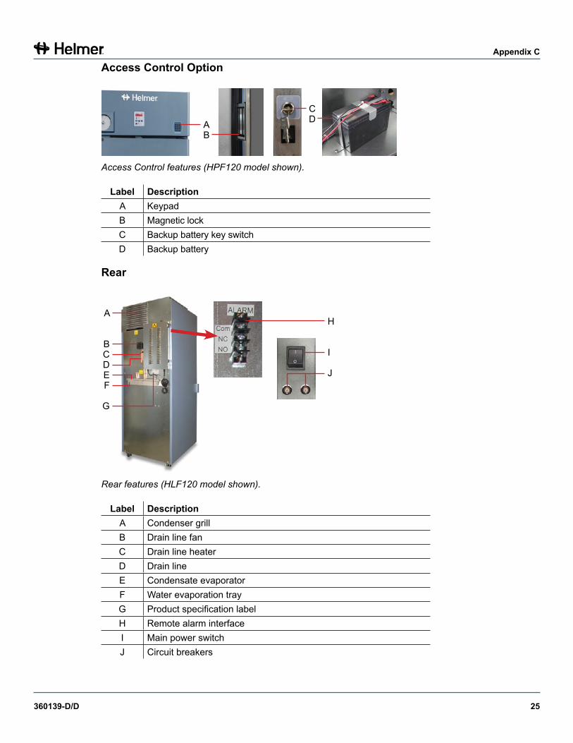
Access Control features (HPF120 model shown).
Label DescriptionA KeypadB Magnetic lockC Backup battery key switchD Backup battery
Rear
H
I
J
A
BCDEF
G
Rear features (HLF120 model shown).
Label DescriptionA Condenser grillB Drain line fanC Drain line heaterD Drain lineE Condensate evaporatorF Water evaporation trayG Product specification labelH Remote alarm interfaceI Main power switchJ Circuit breakers
360139-D/D 26
Appendix C
Top
A B C D
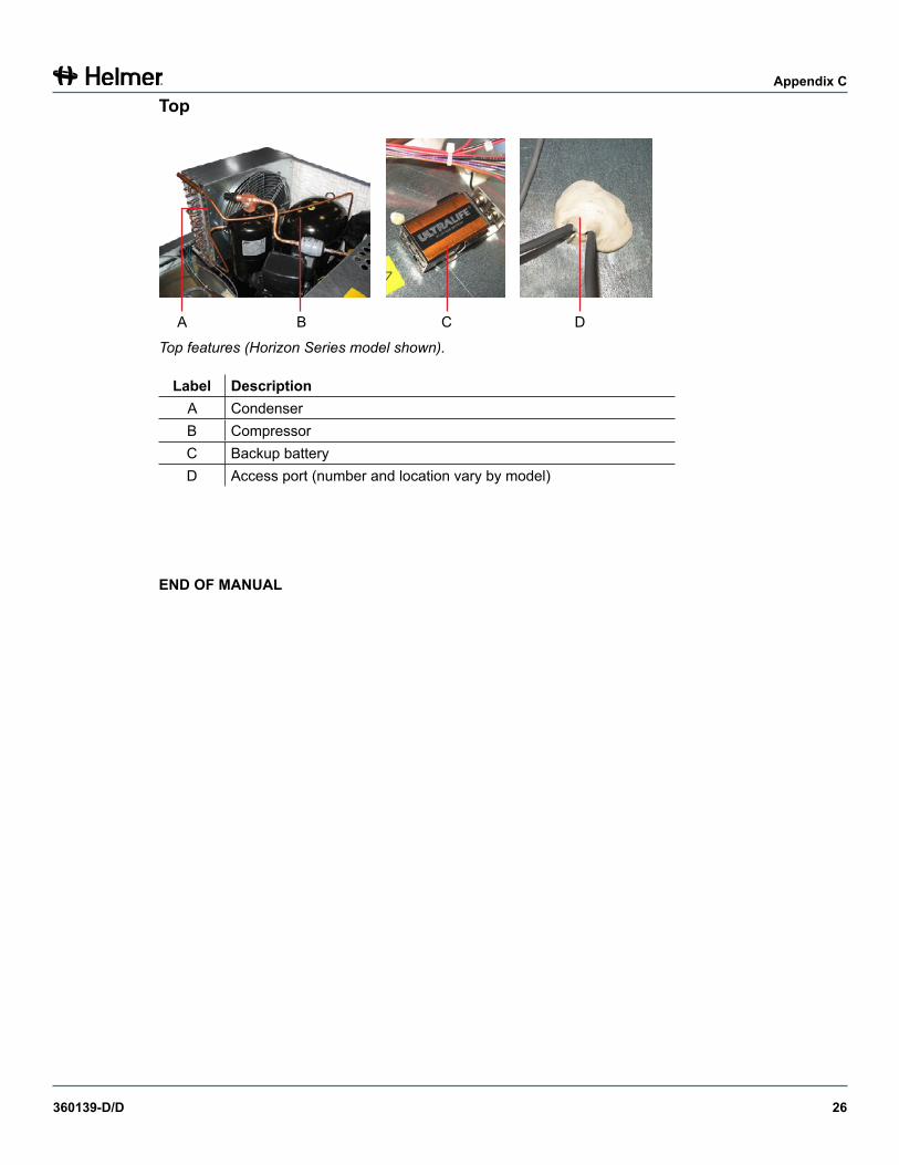
Top features (Horizon Series model shown).
Label DescriptionA CondenserB CompressorC Backup batteryD Access port (number and location vary by model)
ENDOFMANUAL


HELMER SCIENTIFIC14400 Bergen BoulevardNoblesville, IN 46060 USA
PH +1.317.773.9073FAX +1.317.773.9082www.helmerinc.com