Embed Size (px)
Citation preview
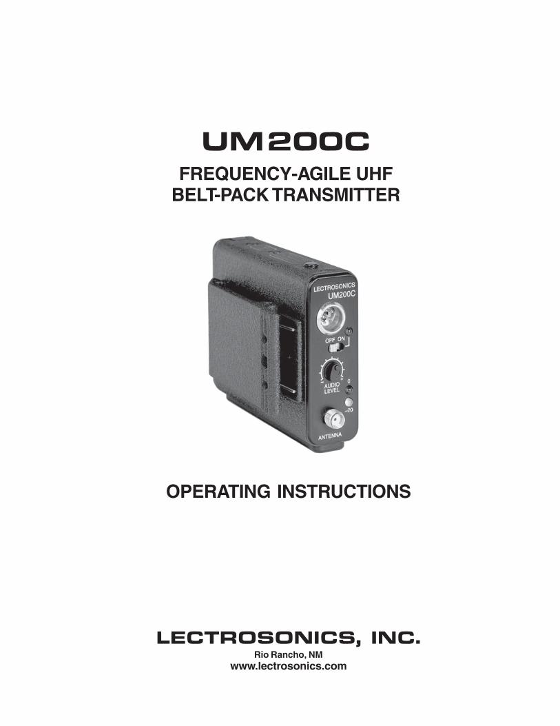
UM200C FREQUENCY-AGILE UHF
BELT-PACK TRANSMITTER
OPERATING INSTRUCTIONS
LECTROSONICS INC Rio Rancho NM
wwwlectrosonicscom
UM200C
TABLE OF CONTENTS
INTRODUCTION 3
GENERAL TECHNICAL DESCRIPTION 4
CONTROLS AND FUNCTIONS 6
BATTERY INSTALLATION 8
OPERATING INSTRUCTIONS 8
OPERATING NOTES 9
ADJUSTING THE TRANSMITTER FREQUENCY 9
MICROPHONE CORD TERMINATION 10
5-PIN INPUT JACK WIRING 11
TROUBLESHOOTING 14
SPECIFICATIONS AND FEATURES 15
SERVICE AND REPAIR 16
RETURNING UNITS FOR REPAIR 16
WARRANTY Back cover
The UM200C transmitter is FCC type accepted under Part 74 470-608MHz and 614-802MHz
LECTROSONICS INC 2
Frequency Agile UHF Belt-Pack Transmitter
INTRODUCTION
Thank you for selecting the Lectrosonics UM200C frequency agile belt-pack transshymitter The UM200C combines over 80 years of engineering experience with the very latest components in a design that addresses the most demanding professional applications
The design of the UM200C was the direct result of numerous conversations with users staging and touring companies and dealers across the US The specific concerns and needs brought up in these conversations led directly to the developshyment of the operational features offered on the UM200C Two hundred fifty six frequencies are user selectable in 100kHz steps to alleviate interference problems in travelling venues and the low frequency roll-off is user adjustable to adapt to varying acoustic environments and preferences
The UM200C is a rugged machined aluminum package with a removable spring loaded belt clip The input section provides a correct input tap for virtually any microphone or line level audio source 5 Volts of bias voltage is available to power electret mics with either positive or negative bias Level indicating LEDs are provided on the control panel to make level settings quick and accurate without having to view the receiver The battery compartment accepts any 9 Volt alkaline battery and makes a positive connection via self-adjusting contacts The antenna is a detachshyable locking 14 wavelength flexible bronze cable that connects to a 50 Ohm SMA port on the transmitter
Only the UM200C transmitter is covered in this manual Companion receivers are covered in separate manuals The UM200C will operate with any 200 Series Lecshytrosonics receiver in the same frequency group
Rio Rancho NM ndash USA 3
UM200C
GENERAL TECHNICAL DESCRIPTION
The UM200C transmitters are comprised of a number of functional sub-systems as shown in the block diagram below
GENERAL The 200 system uses 75kHz wide deviation for an extremely high signal to noise ratioThe transmitter circuits are all regulated to allow full output power from the beginning (9 Volts) to the end (65 Volts) of battery life The input amplishyfier uses a Motorola 33078 op amp for ultra low noise operation It is gain controlled with a wide range input compresshysor which cleanly limits input signal peaks over 30dB above full modulation
DUAL BAND COMPANDOR Traditionally compandors have been a source of distortion in wireless microphone systems The basic problem with conventional systems is that the attack and decay times are always a compromise If the time constants are fast high frequency transients will not be distorted but this will cause low frequency distortion If the time constants are slower low frequency audio distortion will be low but high frequency transients will then be distorted The 200 system introduces an entirely new approach to solving this basic problem called ldquodual-band compandingrdquo
There are actually two separate compandors in the 200 system one for high frequencies and one for low frequencies A crossover network separates the frequency bands at 1kHz with a 6dB per octave slope followed by separate high and low frequency compandors The attack and release times in the high frequency compandor are fast enough to keep high frequency transient distortion at a low level and the low frequency compandor uses slower time constants reducing low frequency distortion to well below that of a conventional compandor
Vref
BASS
TREBLE
LP FILTER
HP FILTER
SET LED
LIMIT LED
COMPANDOR
Vreg
Vreg
+5VDC
+36VDC
SHUNT LIMITER
INPUT AMP
AUDIO LEVEL
LP FILTER
PEAK AUDIO INDICATOR amp
LIMITER DRIVER
PILOT TONE OSC
5 4 3 2 1
MIC JACK
+5V BIAS SUPPLY LF
ROLL-OFF
COMPANDED AUDIO TO XMTR
COMPANDED AUDIO
PHASE LOCKED LOOP
FREQ SWITCHES
DIVIDER
LOW PASS FILTER
PRESCALER
BUFFER
PWR DELAY
+9VDC
PWR LED
VOLTAGE CONTROLLED OSCILLATOR
50 CIRCULATOR ISOLATOR
lt--See 5-Pin Input Jack Wiring for details
TRANSMITTER
UM200C Block Diagram
LECTROSONICS INC 4
Frequency Agile UHF Belt-Pack Transmitter
NO PRE-EMPHASISDE-EMPHASIS The signal to noise ratio of the 200 system is high enough to preclude the need for conventional pre-emphasis (HF boost) in the transmitter and de-emphasis (HF roll off) in the receiver Pre-emphasis and de-emphasis in an FM radio system usually provides about a 10dB improvement in the signal to noise ratio of the system but the high frequency boost in the transmitter must be removed in a purely complementary manner or else the frequency response of the original audio signal will be altered
Pre-emphasis can also cause distortion in the receiver As this signal is passed through the IF filters in the receiver distortion can be produced most noticeable at full modulation De-emphasis cannot be applied until the signal is converted into audio so there is no way around this problem short of eliminating pre-emphasis altogether Neither of these problems occur in the 200 system The dual-band compandor in the 200 Series system essentially provides a dynamic pre-emphasisde-emphasis function with extremely low distortion
PILOT TONE SQUELCH The 200 system utilizes an ultrasonic tone modulation of the carrier to operate the receiver squelch This ldquopilot tonerdquo consists of a 32kHz signal mixed with the audio signal following the microphone preamp just after the compandor to control the audio output muting of the receiver The pilot tone is filtered out of the audio signal immediately after the detector in the receiver so that it does not influence the compandor or various gain stages The basic benefit of the pilot tone squelch system is that the receiver will remain muted until it receives the pilot tone from the matching transmitter even if a strong RF signal is present on the carrier frequency of the system This is extremely important in applications that include an automatic microphone mixer
WIDE-BAND DEVIATION plusmn75kHz deviation improves the capture ratio signal to noise ratio and AM rejection of a wireless system dramatically compared to the more commonly used plusmn15kHz deviation
LONG BATTERY LIFE High efficiency circuits throughout the design allow over 45 hours of operation using a single 9 Volt alkaline battery (A 9V lithium battery will provide over 14 hours of operation) The battery compartment is a unique mechanical design which automatically adjusts to fit any brand of battery The battery contacts are spring loaded to prevent ldquorattlerdquo as the unit is handled
FREQUENCY AGILITY The transmitter section uses a synthesized frequency selectable main oscillator The frequency is extremely stable over a wide temperature range and over time
Two rotary switches located on the side panel of the unit provide 256 frequencies in 100kHz steps over a 255MHz range This alleviates carrier interference problems in mobile or travelling applications
ANTENNA At UHF frequencies where wavelengths and antennas are shorter than at VHF frequencies a resonant length wire is preferred over using the microphone cable as the antenna The antenna on the UM200C consists of a flexible 14 wavelength bronze cable detachable via an SMA connector The impedance of this connector is 50 Ohms
Rio Rancho NM ndash USA 5
UM200C
CONTROLS AND FUNCTIONS
ANTENNA
OFF ON
ndash20
0
LECTROSONICS
LEVEL AUDIO
UM200C
ADJUST
FREQUENCY 16M 100K
0
1 2
3 4 5
6 789
A B C D
E F
0
1 2
3 4 5
6 789
A B C D
E F
LF ROLL OFF 35 150
75 Hz
FREQUENCY ADJUST
LF ROLL-OFF
INPUT JACK The input on the UM200C accommodates virtually every lavalier hand-held or shotgun microphone available Line level signals can also be accommodated Use a Switchcraft TA5F connector on the cord See the separate sheet titled ldquoTransmitter 5-Pin Input Jack Wiringrdquo regarding the correct connections for various microphones and other sources
ONOFF SWITCH Turns the battery power on and off Even when the switch is turned off or on abruptly the pilot tone muting system prevents ldquothumpsrdquo or transients from occurring
ldquoONrdquo LAMP Glows brightly when the battery is good and the ONOFF switch is ON A weak or dim lamp means that the battery is weak When the light goes out there is about 15 to 30 minutes of operation left If the lamp fails to light the battery should be replaced
The ldquoONrdquo lamp is connected to a precision battery test circuit that continuously monitors battery voltage The LED is at full brightness with a new 9 Volt alkaline battery As the battery voltage drops during use the LED brightness will also decrease After about 45 hours of operation the battery voltage will be about 65 Volts and the LED will be completely out
FREQUENCY ADJUST These two rotary switches adjust the center frequency of the carrier The 16M is a coarse adjustment and the 100K is the fine adjustment Each transmitter is factory aligned at the center of its operating range The default position of the frequency select switches is in the center of the transmitterrsquos range
0 1 2
3 4 5
6 789
A B C D
E F 0 1
2 3 4 5
6 789
A B C D
E F
LECTROSONICS INC 6
Frequency Agile UHF Belt-Pack Transmitter
Since the internal circuits are all tightly regulated and the RF output stage has a separate discrete regulator the transmitter will continue to operate to a battery voltage of 65 Volts From 65 Volts to 6 Volts the transmitter will still operate but with degraded performance Please note that a weak battery will sometimes light the POWER LED immediately after turn on but will soon discharge to the point where the LED will go out just like a flashlight with ldquodeadrdquo batteries
The combination of an accurate battery condition indicator and regulation of all internal circuits provides much longer battery life as well as consistent performance over the life of the battery
MODULATION LEDS Indicate the proper setting of the MIC LEVEL control
ldquo-20rdquo LED -- Flickers or glows when sufficient audio is present
ldquo0rdquo LED -- Lights up when the input level is high enough to cause limiting The input limiter has a very high overload threshold (over 30 dB) Generally speaking some limiting is desirable in normal operation to improve the signal to noise ratio of the system The limiting action is not audible and does not create distorshytion A highly trained ear would hear only the compression of the peaks in the audio signal which is desirshyable with most tape recorders and many sound reinforcement systems
AUDIO LEVEL Used to adjust the audio input level for the proper modulation
ANTENNA The flexible wire antenna supplied with the transmitter is cut to 14 wavelength of the center of the frequency block (the frequency range) of the transmitter It is removable via an SMA connector The SMA connector is a 50 Ohm RF port which can also be connected directly to test equipment Replacement antennas are available in pre-cut lengths for specific frequency blocks or as a kit with instructions to cut the antenna for any frequency block
ADJUSTABLE LOW FREQUENCY ROLL-OFF A 18dB per octave low frequency roll-off is provided in the audio section with the -3dB point adjustable from 35Hz to 150Hz The actual roll-off frequency will vary somewhat according to the low frequency response of the mic capsule being used
The low frequency roll-off control is used to prevent undesirable subsonic (or very low frequency) audio often proshyduced by air conditioning systems automobile traffic and other sources from causing the compandor to mistrack Excessive low frequency content in the audio input can cause ldquopumping and breathingrdquo of background noise or modulation of the program audio in recording applications In sound reinforcement systems excessive low frequency content can cause excessive power amplifier drain or even damage to loudspeaker systems By rotating the control clockwise the hinge point of the roll-off is increased to reduce the level of low frequencies In controlled situations such as a motion picture production set indoors where environmental noise is minimal the control can be rotated counter-clockwise to permit low frequency audio to be captured
THE BELT CLIP The belt clip may be removed for special applications by removing one screw
USE ONLY THE SCREW THAT IS SUPPLIED
The circuitry is tightly packed into this unit A longer screw will permanently damage the transmitter Use only Lectrosonics PN28528 which is a Phillips head 4-40 x 316 FL100 screw
Rio Rancho NM ndash USA 7
UM200C
BATTERY INSTALLATION
The transmitter is powered by a standard alkaline or lithium 9 Volt battery It is important that you use ONLY an ALKALINE or LITHIUM battery for longest life Standard zinc-carbon batteries marked ldquoheavy-dutyrdquo or ldquolongshylastingrdquo are not adequate Ni-cad rechargeable batteries will only provide 15 hours of operation or less and will run down quite abruptly Alkaline batteries provide over 45 hours of operation Lithium batteries can be used to provide up to 14 hours Care should be taken not to leave a fully discharged lithium battery in the transmitter as swelling of the battery can make it difficult to remove from the compartment The battery status circuitry is designed for the voltage drop over the life of alkaline batteries
To open the battery compartment press outward on the cover door in the direction of the arrow as shown in the drawing Only firm sliding pressure is needed to open and close the battery door Swing the door open and take note of the polarity marked inside showing the location of the positive (+) and negative (-) terminals You can see the large and small contact holes inside the battery compartment with the door open
Swing the door openPress outward on the
battery door in this direction
Insert the battery correctly and close the cover by pressing the door closed and across reversing the opening proceshydure illustrated above If the battery is inserted incorrectly the door will not close Do not force the door closed
OPERATING INSTRUCTIONS
1) Install a fresh battery according to the instructions above
2) Insert the microphone plug into the input jack aligning the pins be sure that the connector locks in
3) Attach the antenna to the SMA connector on the top of the transmitter
4) Mute the sound system
5) Turn the transmitter power switch to the ldquoONrdquo position
6) Position the microphone in the location you will use in actual operation
LECTROSONICS INC 8
Frequency Agile UHF Belt-Pack Transmitter
7) While speaking or singing at the same voice level that will actually be used observe the MODULATION LEDs Adjust the AUDIO LEVEL control knob until the LEDs begin to light Start at a low setting where neither LED lights as you speak Gradually turn the gain up until one LED lights then the other
The -20 LED lights when the audio level is about 12dB below full modulation The ldquo0rdquo LED lights when the limiter begins to operate There is over 30dB of limiting range without overload above the ldquo0rdquo LED so it is desirable that the it lights up occasionally during use
8) Once the gain has been adjusted the audio system audio can be turned on to make level adjustments Set the power switch to the ON position and adjust the receiver andor sound system level as required Please note there will be a delay between the moment the switch is thrown and the time when audio will actually appear at the receiver output This intentional delay eliminates turn on thumps and is controlled by the pilot tone squelch control
OPERATING NOTES
The AUDIO LEVEL control knob should not be used to control the volume of your sound system or recorder levels This gain adjustment matches the transmitter gain with the userrsquos voice level and microphone positioning
If the audio level is too high mdash both LEDs will light frequently or stay lit This condition may reduce the dynamic range of the audio signal
If the audio level is too low mdash neither LED will light or the -20 LED will light dimly This condition may cause hiss and noise in the audio or pumping and breating in the background noise
The first LED turns on 12dB below full deviation The ldquo0rdquo LED turns on at full deviation and indicates that the input shunt compressor is operating The input limiter will handle peaks over 30dB above full modulation regardless of the gain control setting The limiter uses a true absolute value circuit to detect both positive and negative peaks The attack time is 5 milliseconds and the release time is 200 milliseconds Occasional limiting is desirable indicating that the gain is correctly set and the transmitter is fully modulated for optimum signal to noise ratio
Different voices will usually require different settings of the AUDIO LEVEL control so check this adjustment as each new person uses the system If several different people will be using the transmitter and there is not time to make the adjustment for each individual adjust it for the loudest voice
ADJUSTING THE TRANSMITTER FREQUENCY If you are experiencing interference from another signal on your frequency you may want to change the operating frequency of your system The left switch changes the operating frequency by 16 MHz per step and the right switch changes it 100 kHz per step If you are experiencing interference change the operating frequency in 100 kHz steps to find a clear channel If it is not possible to find a clear channel using the 100 kHz switch return it to its original position and change the 16 MHz switch by one click then try the 100 kHz switch again
To gain access to these switches slide the access door sideways with a fingernail
Note With the UDR200A receiver these switches also appear on the front panel of the receiver Normally you should set the transmitter switches to match the receiver switch settings
0 1 2
3 4 5
6 789
A B C D
E F 0 1
2 3 4 5
6 789
A B C D
E F
With the UDR200B receiver the front panel LED character display will indicate the correct transmitter switch settings
Rio Rancho NM ndash USA 9
UM200C
MICROPHONE CORD TERMINATION
1
2 3
45
VIEW FROM SOLDER SIDE OF PINS
03
015 Heatshrink Tubing
TA5F Connector Assembly
Mic Cord Stripping Instructions
Caution Do not allow the shield wire to touch any metal part of the connector shell The shield wire is the antenna on VHF models and poor operating range will result
Shield Wire
Crimp Tabs
Rubber InsulationCrimp
TabsRubber Insulation
NoteThis termination is required on VHF transmitters and will still work fine on UHF transmitters
LECTROSONICS INC 10
Frequency Agile UHF Belt-Pack Transmitter
5-PIN INPUT JACK WIRING
The wiring diagrams shown on the next page represent the basic wiring necessary for the most common types of microphones and other audio inputs Some microphones may require extra jumpers or a slight variation on the diashygrams shown
Caution - When wiring the connector do not use the connector body for any electrical connections A common mistake is to use the connector body as an audio ground The connector body is
already used as an RF ground on VHF models and no other use is permitted
Itrsquos virtually impossible to keep completely up to date on changes that other manufacturers make to their products It is possible that you may encounter a microphone that differs from these instructions If this occurs please call our toll-free number listed on page 13 of this instruction manual Our service department can answer your questions regarding microphone compatibility
When used on a wireless transmitter the microphone element is in the proximity of the RF coming from the transmitter The nature of electret microphones makes them sensitive to RF which can cause problems with the microphone transmitter compatibility If the electret microphone is not designed properly for use with wireless transmitters it may be necessary to install a chip capacitor in the mic capsule or connector to block the RF from entering the electret capsule This modification is shown on the next page
FB
10k
1k5
100 4
3
2
1
+
POS BIAS (OR GND)
MIC
SOURCE LOAD
LINE IN
NEG GND (OR BIAS) +
1k
10uF330pF
330pF
330pF
330pF
4 3
21 5
LECTROSONICS 5V Mic Bias
To Mic Amp
Input Jack Input Circuit
VHF transmitters use the shield of the microphone cord as the antenna The UM200C uses a 14 wave flexible wire to radiate the RF signal There is really not much difference between these two approaches with respect to the effect of the RF on the microphone capsule Even in transmitters that utilize a ldquodangling wirerdquo the microphone is still part of the ldquoground planerdquo and is therefore still in the antenna circuit
PIN 1 Shield (ground) for positive biased electret lavalier microphones Bias voltage source for negative biased electret lavalier microphones Shield (ground) for dynamic microphones and line level inputs
PIN 2 Shield (ground) for negative biased electret lavalier microphones Bias voltage source for positive biased electret lavalier microphones
PIN 3 Low impedance microphone level input for dynamic microphones Also accepts hand-held electret microshyphones provided the microphone has its own built-in battery
PIN 4 1K Ohm source load for non-Lectrosonics electret microphones Use in conjunction with other pins to provide attenuation of high level input signals
PIN 5 High impedance line level input for tape decks mixer outputs musical instruments etc
Rio Rancho NM ndash USA 11
UM200C
RF BYPASSING 2 WIRE MIC 3 WIRE MIC
Some mics require RF protection to keep the radio signal from affecting the capsule even though the transmitter input circuitry is already RF bypassed (see schematic diagram)
If the mic is wired as directed and you are having difficulty with squealing high noise or poor frequency response RF is likely to be the cause
The best RF protection is accomplished by installing RF bypass capacitors at the mic capsule If this is not possible or if you are still having problems capacitors can be installed on the mic wires inside the TA5F connector housing
Install the capacitors as follows Use 330 pF capacitors Capacitors are available from Lectrosonics Please specify the part number for the desired lead style
Leaded capacitors PN 15117 Leadless capacitors PN SCC330P
All Lectrosonics lavalier mics are already bypassed and do not need any additional capacitors installed for proper operation
BODY GROUND Caution - When wiring the connector do not use the connector body for any electrical connections A common mistake is to use the connector body as an audio ground The connector body is already used as an RF ground on VHF models and no other use is permitted
LINE LEVEL SIGNALS The normal hookup for line level signals is Signal Hot to pin 5 Signal Gnd to pin 1 pin 4 jumped to pin 1 and pin 3 jumped to pin 1 This gives a 40dB attenuator that allows signal levels much higher than 3V to be applied without limiting
If more headroom is needed insert a 100k resistor in series with pin 5 Put this resistor inside the TA5F connector to minimize noise pickup
If lower than normal line levels (less than 1V) are expected use this hookup Signal Hot to pin 5 Signal Gnd to pin 1 and pin 4 jumpered to pin 1 This provides a 20dB attenuator allowing signals as high as 3V to be applied without limiting
WIRING HOOKUPS FOR DIFFERENT SOURCES
CAPSULE CAPSULE
SHIELD
AUDIO
SHIELD
AUDIO
BIAS TA5F
CONNECTOR TA5F
CONNECTOR
Preferred locations for bypass capacitors
Alternate locations for bypass capacitors
PIN
123
4 5
PIN SHIELD 11
AUDIO 22
2 WIRE ELECTRET MIC3 WIRE ELECTRET MIC 3
POSITIVE BIAS 3
NEGATIVE BIAS
1 23
4 5
44 TA5F 5
TA5F 5 PLUGPLUG
SHIELD
AUDIO
BIAS
SLEEVEPIN PINSHIELD SHIELD 1
TIP
1 2 2AUDIOAUDIO2 WIRE ELECTRET MIC 3 3POSITIVE BIAS 4
123
4 5
LINE LEVEL
1 23
4 5
4TA5F TA5FRCA or 14 PLUG 5 PLUG 5 PLUG(See notes on lsquoLINE LEVEL SIGNALSrdquo above)
3
12 PINPIN PIN
Dynamic LO Z mic or electret with manufacturers power supply
SHIELD 1 11 2 22
3 33
1 23
4 5
44
123
4 5
DYNAMIC TA5FTA5F MIC LEVEL 55 PLUGPLUG
SHIELD
BIAS
AUDIO 3 WIRE ELECTRET MIC
NEGATIVE BIAS
LECTROSONICS INC 12
Frequency Agile UHF Belt-Pack Transmitter
TROUBLESHOOTING
Before going through the following chart be sure that you have a good battery in the transmitter It is important that you follow these steps in the sequence listed
SYMPTOM POSSIBLE CAUSE
TRANSMITTER BATTERY LED OFF 1) Battery is inserted backwards 2) Battery is dead
NO TRANSMITTER MODULATION LEDs 1) Gain control turned all the way down 2) Battery is in backwards Check power LED 3) Mic capsule is damaged or malfunctioning 4) Mic cable damaged or mis-wired
RECEIVER RF LAMP OFF 1) Transmitter not turned on 2) Transmitter battery is dead 3) Receiver antenna missing or improperly positioned 4) Transmitter and receiver not on same frequency Check
switchesdisplay on transmitter and receiver 5) Operating range is too great 6) Transmitter antenna not connected
NO SOUND (OR LOW SOUND LEVEL) RECEIVER MOD LEVEL LEDs ARE ON 1) Receiver output level set too low
2) Receiver output is disconnected cable is defective or mis-wired
3) Sound system or recorder input is turned down
DISTORTED SOUND 1) Transmitter gain (audio level) is far too high Check mod level lamps on transmitter and receiver as it is being used (refer to pages 89 for details on gain adjustment)
2) Receiver output may be mis-matched with the sound system or recorder input Adjust output level on receiver to the correct level for the recorder mixer or sound system
3) Excessive wind noise or breath ldquopopsrdquo Re-position microphone andor use a larger windscreen
4) Transmitter is not set to same frequency as receiver Check that frequency select switches on receiver and transmitter match
HISS AND NOISE -- AUDIBLE DROPOUTS 1) Transmitter gain (audio level) far too low 2) Receiver antenna missing or obstructed 3) Transmitter antenna missing 4) Operating range too great
EXCESSIVE FEEDBACK 1) Transmitter gain (audio level) too high Check gain adjustment andor reduce receiver output level
2) Transmitter too close to speaker system 3) Mic is too far from userrsquos mouth
Rio Rancho NM ndash USA 13
UM200C
SPECIFICATIONS AND FEATURES
Operating frequencies 537600 to 607900 MHz 614100 to 767900 MHz
Frequency selection 256 frequencies in 100kHz steps
RF Power output 100 mW (nominal)
Pilot tone 32764 kHz (plusmn 2Hz) 5kHz deviation
Frequency stability plusmn 0002
Deviation plusmn 75 kHz (max)
Spurious radiation 90 dB below carrier
Equivalent input noise ndash126 dBV
Input level Nominal 2 mV to 300 mV before limiting Greater than 50V maximum with limiting
Input impedance Taps provided for 500 1k 10k Ohm
Input compressor Soft compressor gt30 dB range
Gain control range 43 dB semi-log rotary control
Modulation indicators Dual LEDs indicate modulation level 12dB below limiting and at the onset of limiting
Low frequency roll-off adjustment ndash18dBoctave 35Hz to 150Hz
Controls 2 position ldquoOFF-ONrdquo slide switch for noiseless turn onturn off operation Front panel knob adjusts audio gain Recessed control on side panel
adjusts low frequency rolloff Rotary switches on side panel adjust transmitter frequency
Audio Input Jack Switchcraft 5 pin locking (TA5F)
Antenna Detachable flexible wire supplied 50 Ohm port allows connection to test equipment
Battery Precision compartment auto-adjusts to accept any known alkaline 9 Volt battery (Wersquove tried 125 different ones)
Battery Life 45 hours (alkaline) 14 hours (lithium)
Weight 63 ozs including battery
Dimensions 31 x 24 x 75 inches
Emission Designator 180KF3E
Specifications subject to change without notice
LECTROSONICS INC 14
Frequency Agile UHF Belt-Pack Transmitter
SERVICE AND REPAIR
If your system malfunctions you should attempt to correct or isolate the trouble before concluding that the equipment needs repair Make sure you have followed the setup procedure and operating instructions Check out the interconshynecting cords and then go through the TROUBLESHOOTING section in the manual
We strongly recommend that you do not try to repair the equipment yourself and do not have the local repair shop attempt anything other than the simplest repair If the repair is more complicated than a broken wire or loose connecshytion send the unit to the factory for repair and service Donrsquot attempt to adjust any controls inside the units Once set at the factory the various controls and trimmers do not drift with age or vibration and never require readjustment There are no adjustments inside that will make a malfunctioning unit start working
LECTROSONICS service department is equipped and staffed to quickly repair your equipment In-warranty repairs are made at no charge in accordance with the terms of the warranty Out-of-warranty repairs are charged at a modest flat rate plus parts and shipping Since it takes almost as much time and effort to determine what is wrong as it does to make the repair there is a charge for an exact quotation We will be happy to quote approximate charges by phone for out-of-warranty repairs
RETURNING UNITS FOR REPAIR You will save yourself time and trouble if you will follow the steps below
A DO NOT return equipment to the factory for repair without first contacting us by letter or by phone We need to know the nature of the problem the model number and the serial number of the equipment We also need a phone number where you can be reached 8 am to 4 pm (Mountain Standard Time)
B After receiving your request we will issue you a return authorization number (RA) This number will help speed your repair through our receiving and repair departments The return authorization number must be clearly shown on the outside of the shipping container
C Pack the equipment carefully and ship to us shipping costs prepaid If necessary we can provide you with the proper packing materials UPS is usually the best way to ship the units Heavy units should be ldquodouble-boxedrdquo for safe transport
D We also strongly recommend that you insure the equipment since we cannot be responsible for loss of or damage to equipment that you ship Of course we insure the equipment when we ship it back to you
Mailing address Shipping address Lectrosonics Inc Lectrosonics Inc PO Box 15900 581 Laser Rd Rio Rancho NM 87174 Rio Rancho NM 87124 USA USA
Telephones Regular (505) 892-4501 Toll Free (800) 821-1121 FAX (505) 892-6243
World Wide Web httpwwwlectrosonicscom Email saleslectrosonicscom
Rio Rancho NM ndash USA 15
LIMITED ONE YEAR WARRANTY
The equipment is warranted for one year from date of purchase against defects in materials or workmanship provided it was purchased from an authorized dealer This warranty does not cover equipment which has been abused or damaged by careless handling or shipping This warranty does not apply to used or demonstrator equipment
Should any defect develop Lectrosonics Inc will at our option repair or replace any defective parts without charge for either parts or labor If Lectrosonics Inc cannot correct the defect in your equipment it will be replaced at no charge with a similar new item Lectrosonics Inc will pay for the cost of returning your equipment to you
This warranty applies only to items returned to Lectrosonics Inc or an authorized dealer shipping costs prepaid within one year from the date of purchase
This Limited Warranty is governed by the laws of the State of New Mexico It states the entire liablility of Lectrosonics Inc and the entire remedy of the purchaser for any breach of warranty as outlined above NEITHER LECTROSONICS INC NOR ANYONE INVOLVED IN THE PRODUCTION OR DELIVERY OF THE EQUIPMENT SHALL BE LIABLE FOR ANY INDIRECT SPECIAL PUNITIVE CONSEQUENTIAL OR INCIDENTAL DAMAGES ARISING OUT OF THE USE OR INABILITY TO USE THIS EQUIPMENT EVEN IF LECTROSONICS INC HAS BEEN ADVISED OF THE POSSIBILITY OF SUCH DAMAGES IN NO EVENT SHALL THE LIABILITY OF LECTROSONICS INC EXCEED THE PURCHASE PRICE OF ANY DEFECTIVE EQUIPMENT
This warranty gives you specific legal rights You may have additional legal rights which vary from state to state
LIMITED ONE YEAR WARRANTY
LECTROSONICS INC
581 LASER ROAD RIO RANCHO NM 87124 USA wwwlectrosonicscom
November 5 2003
UM200C
TABLE OF CONTENTS
INTRODUCTION 3
GENERAL TECHNICAL DESCRIPTION 4
CONTROLS AND FUNCTIONS 6
BATTERY INSTALLATION 8
OPERATING INSTRUCTIONS 8
OPERATING NOTES 9
ADJUSTING THE TRANSMITTER FREQUENCY 9
MICROPHONE CORD TERMINATION 10
5-PIN INPUT JACK WIRING 11
TROUBLESHOOTING 14
SPECIFICATIONS AND FEATURES 15
SERVICE AND REPAIR 16
RETURNING UNITS FOR REPAIR 16
WARRANTY Back cover
The UM200C transmitter is FCC type accepted under Part 74 470-608MHz and 614-802MHz
LECTROSONICS INC 2
Frequency Agile UHF Belt-Pack Transmitter
INTRODUCTION
Thank you for selecting the Lectrosonics UM200C frequency agile belt-pack transshymitter The UM200C combines over 80 years of engineering experience with the very latest components in a design that addresses the most demanding professional applications
The design of the UM200C was the direct result of numerous conversations with users staging and touring companies and dealers across the US The specific concerns and needs brought up in these conversations led directly to the developshyment of the operational features offered on the UM200C Two hundred fifty six frequencies are user selectable in 100kHz steps to alleviate interference problems in travelling venues and the low frequency roll-off is user adjustable to adapt to varying acoustic environments and preferences
The UM200C is a rugged machined aluminum package with a removable spring loaded belt clip The input section provides a correct input tap for virtually any microphone or line level audio source 5 Volts of bias voltage is available to power electret mics with either positive or negative bias Level indicating LEDs are provided on the control panel to make level settings quick and accurate without having to view the receiver The battery compartment accepts any 9 Volt alkaline battery and makes a positive connection via self-adjusting contacts The antenna is a detachshyable locking 14 wavelength flexible bronze cable that connects to a 50 Ohm SMA port on the transmitter
Only the UM200C transmitter is covered in this manual Companion receivers are covered in separate manuals The UM200C will operate with any 200 Series Lecshytrosonics receiver in the same frequency group
Rio Rancho NM ndash USA 3
UM200C
GENERAL TECHNICAL DESCRIPTION
The UM200C transmitters are comprised of a number of functional sub-systems as shown in the block diagram below
GENERAL The 200 system uses 75kHz wide deviation for an extremely high signal to noise ratioThe transmitter circuits are all regulated to allow full output power from the beginning (9 Volts) to the end (65 Volts) of battery life The input amplishyfier uses a Motorola 33078 op amp for ultra low noise operation It is gain controlled with a wide range input compresshysor which cleanly limits input signal peaks over 30dB above full modulation
DUAL BAND COMPANDOR Traditionally compandors have been a source of distortion in wireless microphone systems The basic problem with conventional systems is that the attack and decay times are always a compromise If the time constants are fast high frequency transients will not be distorted but this will cause low frequency distortion If the time constants are slower low frequency audio distortion will be low but high frequency transients will then be distorted The 200 system introduces an entirely new approach to solving this basic problem called ldquodual-band compandingrdquo
There are actually two separate compandors in the 200 system one for high frequencies and one for low frequencies A crossover network separates the frequency bands at 1kHz with a 6dB per octave slope followed by separate high and low frequency compandors The attack and release times in the high frequency compandor are fast enough to keep high frequency transient distortion at a low level and the low frequency compandor uses slower time constants reducing low frequency distortion to well below that of a conventional compandor
Vref
BASS
TREBLE
LP FILTER
HP FILTER
SET LED
LIMIT LED
COMPANDOR
Vreg
Vreg
+5VDC
+36VDC
SHUNT LIMITER
INPUT AMP
AUDIO LEVEL
LP FILTER
PEAK AUDIO INDICATOR amp
LIMITER DRIVER
PILOT TONE OSC
5 4 3 2 1
MIC JACK
+5V BIAS SUPPLY LF
ROLL-OFF
COMPANDED AUDIO TO XMTR
COMPANDED AUDIO
PHASE LOCKED LOOP
FREQ SWITCHES
DIVIDER
LOW PASS FILTER
PRESCALER
BUFFER
PWR DELAY
+9VDC
PWR LED
VOLTAGE CONTROLLED OSCILLATOR
50 CIRCULATOR ISOLATOR
lt--See 5-Pin Input Jack Wiring for details
TRANSMITTER
UM200C Block Diagram
LECTROSONICS INC 4
Frequency Agile UHF Belt-Pack Transmitter
NO PRE-EMPHASISDE-EMPHASIS The signal to noise ratio of the 200 system is high enough to preclude the need for conventional pre-emphasis (HF boost) in the transmitter and de-emphasis (HF roll off) in the receiver Pre-emphasis and de-emphasis in an FM radio system usually provides about a 10dB improvement in the signal to noise ratio of the system but the high frequency boost in the transmitter must be removed in a purely complementary manner or else the frequency response of the original audio signal will be altered
Pre-emphasis can also cause distortion in the receiver As this signal is passed through the IF filters in the receiver distortion can be produced most noticeable at full modulation De-emphasis cannot be applied until the signal is converted into audio so there is no way around this problem short of eliminating pre-emphasis altogether Neither of these problems occur in the 200 system The dual-band compandor in the 200 Series system essentially provides a dynamic pre-emphasisde-emphasis function with extremely low distortion
PILOT TONE SQUELCH The 200 system utilizes an ultrasonic tone modulation of the carrier to operate the receiver squelch This ldquopilot tonerdquo consists of a 32kHz signal mixed with the audio signal following the microphone preamp just after the compandor to control the audio output muting of the receiver The pilot tone is filtered out of the audio signal immediately after the detector in the receiver so that it does not influence the compandor or various gain stages The basic benefit of the pilot tone squelch system is that the receiver will remain muted until it receives the pilot tone from the matching transmitter even if a strong RF signal is present on the carrier frequency of the system This is extremely important in applications that include an automatic microphone mixer
WIDE-BAND DEVIATION plusmn75kHz deviation improves the capture ratio signal to noise ratio and AM rejection of a wireless system dramatically compared to the more commonly used plusmn15kHz deviation
LONG BATTERY LIFE High efficiency circuits throughout the design allow over 45 hours of operation using a single 9 Volt alkaline battery (A 9V lithium battery will provide over 14 hours of operation) The battery compartment is a unique mechanical design which automatically adjusts to fit any brand of battery The battery contacts are spring loaded to prevent ldquorattlerdquo as the unit is handled
FREQUENCY AGILITY The transmitter section uses a synthesized frequency selectable main oscillator The frequency is extremely stable over a wide temperature range and over time
Two rotary switches located on the side panel of the unit provide 256 frequencies in 100kHz steps over a 255MHz range This alleviates carrier interference problems in mobile or travelling applications
ANTENNA At UHF frequencies where wavelengths and antennas are shorter than at VHF frequencies a resonant length wire is preferred over using the microphone cable as the antenna The antenna on the UM200C consists of a flexible 14 wavelength bronze cable detachable via an SMA connector The impedance of this connector is 50 Ohms
Rio Rancho NM ndash USA 5
UM200C
CONTROLS AND FUNCTIONS
ANTENNA
OFF ON
ndash20
0
LECTROSONICS
LEVEL AUDIO
UM200C
ADJUST
FREQUENCY 16M 100K
0
1 2
3 4 5
6 789
A B C D
E F
0
1 2
3 4 5
6 789
A B C D
E F
LF ROLL OFF 35 150
75 Hz
FREQUENCY ADJUST
LF ROLL-OFF
INPUT JACK The input on the UM200C accommodates virtually every lavalier hand-held or shotgun microphone available Line level signals can also be accommodated Use a Switchcraft TA5F connector on the cord See the separate sheet titled ldquoTransmitter 5-Pin Input Jack Wiringrdquo regarding the correct connections for various microphones and other sources
ONOFF SWITCH Turns the battery power on and off Even when the switch is turned off or on abruptly the pilot tone muting system prevents ldquothumpsrdquo or transients from occurring
ldquoONrdquo LAMP Glows brightly when the battery is good and the ONOFF switch is ON A weak or dim lamp means that the battery is weak When the light goes out there is about 15 to 30 minutes of operation left If the lamp fails to light the battery should be replaced
The ldquoONrdquo lamp is connected to a precision battery test circuit that continuously monitors battery voltage The LED is at full brightness with a new 9 Volt alkaline battery As the battery voltage drops during use the LED brightness will also decrease After about 45 hours of operation the battery voltage will be about 65 Volts and the LED will be completely out
FREQUENCY ADJUST These two rotary switches adjust the center frequency of the carrier The 16M is a coarse adjustment and the 100K is the fine adjustment Each transmitter is factory aligned at the center of its operating range The default position of the frequency select switches is in the center of the transmitterrsquos range
0 1 2
3 4 5
6 789
A B C D
E F 0 1
2 3 4 5
6 789
A B C D
E F
LECTROSONICS INC 6
Frequency Agile UHF Belt-Pack Transmitter
Since the internal circuits are all tightly regulated and the RF output stage has a separate discrete regulator the transmitter will continue to operate to a battery voltage of 65 Volts From 65 Volts to 6 Volts the transmitter will still operate but with degraded performance Please note that a weak battery will sometimes light the POWER LED immediately after turn on but will soon discharge to the point where the LED will go out just like a flashlight with ldquodeadrdquo batteries
The combination of an accurate battery condition indicator and regulation of all internal circuits provides much longer battery life as well as consistent performance over the life of the battery
MODULATION LEDS Indicate the proper setting of the MIC LEVEL control
ldquo-20rdquo LED -- Flickers or glows when sufficient audio is present
ldquo0rdquo LED -- Lights up when the input level is high enough to cause limiting The input limiter has a very high overload threshold (over 30 dB) Generally speaking some limiting is desirable in normal operation to improve the signal to noise ratio of the system The limiting action is not audible and does not create distorshytion A highly trained ear would hear only the compression of the peaks in the audio signal which is desirshyable with most tape recorders and many sound reinforcement systems
AUDIO LEVEL Used to adjust the audio input level for the proper modulation
ANTENNA The flexible wire antenna supplied with the transmitter is cut to 14 wavelength of the center of the frequency block (the frequency range) of the transmitter It is removable via an SMA connector The SMA connector is a 50 Ohm RF port which can also be connected directly to test equipment Replacement antennas are available in pre-cut lengths for specific frequency blocks or as a kit with instructions to cut the antenna for any frequency block
ADJUSTABLE LOW FREQUENCY ROLL-OFF A 18dB per octave low frequency roll-off is provided in the audio section with the -3dB point adjustable from 35Hz to 150Hz The actual roll-off frequency will vary somewhat according to the low frequency response of the mic capsule being used
The low frequency roll-off control is used to prevent undesirable subsonic (or very low frequency) audio often proshyduced by air conditioning systems automobile traffic and other sources from causing the compandor to mistrack Excessive low frequency content in the audio input can cause ldquopumping and breathingrdquo of background noise or modulation of the program audio in recording applications In sound reinforcement systems excessive low frequency content can cause excessive power amplifier drain or even damage to loudspeaker systems By rotating the control clockwise the hinge point of the roll-off is increased to reduce the level of low frequencies In controlled situations such as a motion picture production set indoors where environmental noise is minimal the control can be rotated counter-clockwise to permit low frequency audio to be captured
THE BELT CLIP The belt clip may be removed for special applications by removing one screw
USE ONLY THE SCREW THAT IS SUPPLIED
The circuitry is tightly packed into this unit A longer screw will permanently damage the transmitter Use only Lectrosonics PN28528 which is a Phillips head 4-40 x 316 FL100 screw
Rio Rancho NM ndash USA 7
UM200C
BATTERY INSTALLATION
The transmitter is powered by a standard alkaline or lithium 9 Volt battery It is important that you use ONLY an ALKALINE or LITHIUM battery for longest life Standard zinc-carbon batteries marked ldquoheavy-dutyrdquo or ldquolongshylastingrdquo are not adequate Ni-cad rechargeable batteries will only provide 15 hours of operation or less and will run down quite abruptly Alkaline batteries provide over 45 hours of operation Lithium batteries can be used to provide up to 14 hours Care should be taken not to leave a fully discharged lithium battery in the transmitter as swelling of the battery can make it difficult to remove from the compartment The battery status circuitry is designed for the voltage drop over the life of alkaline batteries
To open the battery compartment press outward on the cover door in the direction of the arrow as shown in the drawing Only firm sliding pressure is needed to open and close the battery door Swing the door open and take note of the polarity marked inside showing the location of the positive (+) and negative (-) terminals You can see the large and small contact holes inside the battery compartment with the door open
Swing the door openPress outward on the
battery door in this direction
Insert the battery correctly and close the cover by pressing the door closed and across reversing the opening proceshydure illustrated above If the battery is inserted incorrectly the door will not close Do not force the door closed
OPERATING INSTRUCTIONS
1) Install a fresh battery according to the instructions above
2) Insert the microphone plug into the input jack aligning the pins be sure that the connector locks in
3) Attach the antenna to the SMA connector on the top of the transmitter
4) Mute the sound system
5) Turn the transmitter power switch to the ldquoONrdquo position
6) Position the microphone in the location you will use in actual operation
LECTROSONICS INC 8
Frequency Agile UHF Belt-Pack Transmitter
7) While speaking or singing at the same voice level that will actually be used observe the MODULATION LEDs Adjust the AUDIO LEVEL control knob until the LEDs begin to light Start at a low setting where neither LED lights as you speak Gradually turn the gain up until one LED lights then the other
The -20 LED lights when the audio level is about 12dB below full modulation The ldquo0rdquo LED lights when the limiter begins to operate There is over 30dB of limiting range without overload above the ldquo0rdquo LED so it is desirable that the it lights up occasionally during use
8) Once the gain has been adjusted the audio system audio can be turned on to make level adjustments Set the power switch to the ON position and adjust the receiver andor sound system level as required Please note there will be a delay between the moment the switch is thrown and the time when audio will actually appear at the receiver output This intentional delay eliminates turn on thumps and is controlled by the pilot tone squelch control
OPERATING NOTES
The AUDIO LEVEL control knob should not be used to control the volume of your sound system or recorder levels This gain adjustment matches the transmitter gain with the userrsquos voice level and microphone positioning
If the audio level is too high mdash both LEDs will light frequently or stay lit This condition may reduce the dynamic range of the audio signal
If the audio level is too low mdash neither LED will light or the -20 LED will light dimly This condition may cause hiss and noise in the audio or pumping and breating in the background noise
The first LED turns on 12dB below full deviation The ldquo0rdquo LED turns on at full deviation and indicates that the input shunt compressor is operating The input limiter will handle peaks over 30dB above full modulation regardless of the gain control setting The limiter uses a true absolute value circuit to detect both positive and negative peaks The attack time is 5 milliseconds and the release time is 200 milliseconds Occasional limiting is desirable indicating that the gain is correctly set and the transmitter is fully modulated for optimum signal to noise ratio
Different voices will usually require different settings of the AUDIO LEVEL control so check this adjustment as each new person uses the system If several different people will be using the transmitter and there is not time to make the adjustment for each individual adjust it for the loudest voice
ADJUSTING THE TRANSMITTER FREQUENCY If you are experiencing interference from another signal on your frequency you may want to change the operating frequency of your system The left switch changes the operating frequency by 16 MHz per step and the right switch changes it 100 kHz per step If you are experiencing interference change the operating frequency in 100 kHz steps to find a clear channel If it is not possible to find a clear channel using the 100 kHz switch return it to its original position and change the 16 MHz switch by one click then try the 100 kHz switch again
To gain access to these switches slide the access door sideways with a fingernail
Note With the UDR200A receiver these switches also appear on the front panel of the receiver Normally you should set the transmitter switches to match the receiver switch settings
0 1 2
3 4 5
6 789
A B C D
E F 0 1
2 3 4 5
6 789
A B C D
E F
With the UDR200B receiver the front panel LED character display will indicate the correct transmitter switch settings
Rio Rancho NM ndash USA 9
UM200C
MICROPHONE CORD TERMINATION
1
2 3
45
VIEW FROM SOLDER SIDE OF PINS
03
015 Heatshrink Tubing
TA5F Connector Assembly
Mic Cord Stripping Instructions
Caution Do not allow the shield wire to touch any metal part of the connector shell The shield wire is the antenna on VHF models and poor operating range will result
Shield Wire
Crimp Tabs
Rubber InsulationCrimp
TabsRubber Insulation
NoteThis termination is required on VHF transmitters and will still work fine on UHF transmitters
LECTROSONICS INC 10
Frequency Agile UHF Belt-Pack Transmitter
5-PIN INPUT JACK WIRING
The wiring diagrams shown on the next page represent the basic wiring necessary for the most common types of microphones and other audio inputs Some microphones may require extra jumpers or a slight variation on the diashygrams shown
Caution - When wiring the connector do not use the connector body for any electrical connections A common mistake is to use the connector body as an audio ground The connector body is
already used as an RF ground on VHF models and no other use is permitted
Itrsquos virtually impossible to keep completely up to date on changes that other manufacturers make to their products It is possible that you may encounter a microphone that differs from these instructions If this occurs please call our toll-free number listed on page 13 of this instruction manual Our service department can answer your questions regarding microphone compatibility
When used on a wireless transmitter the microphone element is in the proximity of the RF coming from the transmitter The nature of electret microphones makes them sensitive to RF which can cause problems with the microphone transmitter compatibility If the electret microphone is not designed properly for use with wireless transmitters it may be necessary to install a chip capacitor in the mic capsule or connector to block the RF from entering the electret capsule This modification is shown on the next page
FB
10k
1k5
100 4
3
2
1
+
POS BIAS (OR GND)
MIC
SOURCE LOAD
LINE IN
NEG GND (OR BIAS) +
1k
10uF330pF
330pF
330pF
330pF
4 3
21 5
LECTROSONICS 5V Mic Bias
To Mic Amp
Input Jack Input Circuit
VHF transmitters use the shield of the microphone cord as the antenna The UM200C uses a 14 wave flexible wire to radiate the RF signal There is really not much difference between these two approaches with respect to the effect of the RF on the microphone capsule Even in transmitters that utilize a ldquodangling wirerdquo the microphone is still part of the ldquoground planerdquo and is therefore still in the antenna circuit
PIN 1 Shield (ground) for positive biased electret lavalier microphones Bias voltage source for negative biased electret lavalier microphones Shield (ground) for dynamic microphones and line level inputs
PIN 2 Shield (ground) for negative biased electret lavalier microphones Bias voltage source for positive biased electret lavalier microphones
PIN 3 Low impedance microphone level input for dynamic microphones Also accepts hand-held electret microshyphones provided the microphone has its own built-in battery
PIN 4 1K Ohm source load for non-Lectrosonics electret microphones Use in conjunction with other pins to provide attenuation of high level input signals
PIN 5 High impedance line level input for tape decks mixer outputs musical instruments etc
Rio Rancho NM ndash USA 11
UM200C
RF BYPASSING 2 WIRE MIC 3 WIRE MIC
Some mics require RF protection to keep the radio signal from affecting the capsule even though the transmitter input circuitry is already RF bypassed (see schematic diagram)
If the mic is wired as directed and you are having difficulty with squealing high noise or poor frequency response RF is likely to be the cause
The best RF protection is accomplished by installing RF bypass capacitors at the mic capsule If this is not possible or if you are still having problems capacitors can be installed on the mic wires inside the TA5F connector housing
Install the capacitors as follows Use 330 pF capacitors Capacitors are available from Lectrosonics Please specify the part number for the desired lead style
Leaded capacitors PN 15117 Leadless capacitors PN SCC330P
All Lectrosonics lavalier mics are already bypassed and do not need any additional capacitors installed for proper operation
BODY GROUND Caution - When wiring the connector do not use the connector body for any electrical connections A common mistake is to use the connector body as an audio ground The connector body is already used as an RF ground on VHF models and no other use is permitted
LINE LEVEL SIGNALS The normal hookup for line level signals is Signal Hot to pin 5 Signal Gnd to pin 1 pin 4 jumped to pin 1 and pin 3 jumped to pin 1 This gives a 40dB attenuator that allows signal levels much higher than 3V to be applied without limiting
If more headroom is needed insert a 100k resistor in series with pin 5 Put this resistor inside the TA5F connector to minimize noise pickup
If lower than normal line levels (less than 1V) are expected use this hookup Signal Hot to pin 5 Signal Gnd to pin 1 and pin 4 jumpered to pin 1 This provides a 20dB attenuator allowing signals as high as 3V to be applied without limiting
WIRING HOOKUPS FOR DIFFERENT SOURCES
CAPSULE CAPSULE
SHIELD
AUDIO
SHIELD
AUDIO
BIAS TA5F
CONNECTOR TA5F
CONNECTOR
Preferred locations for bypass capacitors
Alternate locations for bypass capacitors
PIN
123
4 5
PIN SHIELD 11
AUDIO 22
2 WIRE ELECTRET MIC3 WIRE ELECTRET MIC 3
POSITIVE BIAS 3
NEGATIVE BIAS
1 23
4 5
44 TA5F 5
TA5F 5 PLUGPLUG
SHIELD
AUDIO
BIAS
SLEEVEPIN PINSHIELD SHIELD 1
TIP
1 2 2AUDIOAUDIO2 WIRE ELECTRET MIC 3 3POSITIVE BIAS 4
123
4 5
LINE LEVEL
1 23
4 5
4TA5F TA5FRCA or 14 PLUG 5 PLUG 5 PLUG(See notes on lsquoLINE LEVEL SIGNALSrdquo above)
3
12 PINPIN PIN
Dynamic LO Z mic or electret with manufacturers power supply
SHIELD 1 11 2 22
3 33
1 23
4 5
44
123
4 5
DYNAMIC TA5FTA5F MIC LEVEL 55 PLUGPLUG
SHIELD
BIAS
AUDIO 3 WIRE ELECTRET MIC
NEGATIVE BIAS
LECTROSONICS INC 12
Frequency Agile UHF Belt-Pack Transmitter
TROUBLESHOOTING
Before going through the following chart be sure that you have a good battery in the transmitter It is important that you follow these steps in the sequence listed
SYMPTOM POSSIBLE CAUSE
TRANSMITTER BATTERY LED OFF 1) Battery is inserted backwards 2) Battery is dead
NO TRANSMITTER MODULATION LEDs 1) Gain control turned all the way down 2) Battery is in backwards Check power LED 3) Mic capsule is damaged or malfunctioning 4) Mic cable damaged or mis-wired
RECEIVER RF LAMP OFF 1) Transmitter not turned on 2) Transmitter battery is dead 3) Receiver antenna missing or improperly positioned 4) Transmitter and receiver not on same frequency Check
switchesdisplay on transmitter and receiver 5) Operating range is too great 6) Transmitter antenna not connected
NO SOUND (OR LOW SOUND LEVEL) RECEIVER MOD LEVEL LEDs ARE ON 1) Receiver output level set too low
2) Receiver output is disconnected cable is defective or mis-wired
3) Sound system or recorder input is turned down
DISTORTED SOUND 1) Transmitter gain (audio level) is far too high Check mod level lamps on transmitter and receiver as it is being used (refer to pages 89 for details on gain adjustment)
2) Receiver output may be mis-matched with the sound system or recorder input Adjust output level on receiver to the correct level for the recorder mixer or sound system
3) Excessive wind noise or breath ldquopopsrdquo Re-position microphone andor use a larger windscreen
4) Transmitter is not set to same frequency as receiver Check that frequency select switches on receiver and transmitter match
HISS AND NOISE -- AUDIBLE DROPOUTS 1) Transmitter gain (audio level) far too low 2) Receiver antenna missing or obstructed 3) Transmitter antenna missing 4) Operating range too great
EXCESSIVE FEEDBACK 1) Transmitter gain (audio level) too high Check gain adjustment andor reduce receiver output level
2) Transmitter too close to speaker system 3) Mic is too far from userrsquos mouth
Rio Rancho NM ndash USA 13
UM200C
SPECIFICATIONS AND FEATURES
Operating frequencies 537600 to 607900 MHz 614100 to 767900 MHz
Frequency selection 256 frequencies in 100kHz steps
RF Power output 100 mW (nominal)
Pilot tone 32764 kHz (plusmn 2Hz) 5kHz deviation
Frequency stability plusmn 0002
Deviation plusmn 75 kHz (max)
Spurious radiation 90 dB below carrier
Equivalent input noise ndash126 dBV
Input level Nominal 2 mV to 300 mV before limiting Greater than 50V maximum with limiting
Input impedance Taps provided for 500 1k 10k Ohm
Input compressor Soft compressor gt30 dB range
Gain control range 43 dB semi-log rotary control
Modulation indicators Dual LEDs indicate modulation level 12dB below limiting and at the onset of limiting
Low frequency roll-off adjustment ndash18dBoctave 35Hz to 150Hz
Controls 2 position ldquoOFF-ONrdquo slide switch for noiseless turn onturn off operation Front panel knob adjusts audio gain Recessed control on side panel
adjusts low frequency rolloff Rotary switches on side panel adjust transmitter frequency
Audio Input Jack Switchcraft 5 pin locking (TA5F)
Antenna Detachable flexible wire supplied 50 Ohm port allows connection to test equipment
Battery Precision compartment auto-adjusts to accept any known alkaline 9 Volt battery (Wersquove tried 125 different ones)
Battery Life 45 hours (alkaline) 14 hours (lithium)
Weight 63 ozs including battery
Dimensions 31 x 24 x 75 inches
Emission Designator 180KF3E
Specifications subject to change without notice
LECTROSONICS INC 14
Frequency Agile UHF Belt-Pack Transmitter
SERVICE AND REPAIR
If your system malfunctions you should attempt to correct or isolate the trouble before concluding that the equipment needs repair Make sure you have followed the setup procedure and operating instructions Check out the interconshynecting cords and then go through the TROUBLESHOOTING section in the manual
We strongly recommend that you do not try to repair the equipment yourself and do not have the local repair shop attempt anything other than the simplest repair If the repair is more complicated than a broken wire or loose connecshytion send the unit to the factory for repair and service Donrsquot attempt to adjust any controls inside the units Once set at the factory the various controls and trimmers do not drift with age or vibration and never require readjustment There are no adjustments inside that will make a malfunctioning unit start working
LECTROSONICS service department is equipped and staffed to quickly repair your equipment In-warranty repairs are made at no charge in accordance with the terms of the warranty Out-of-warranty repairs are charged at a modest flat rate plus parts and shipping Since it takes almost as much time and effort to determine what is wrong as it does to make the repair there is a charge for an exact quotation We will be happy to quote approximate charges by phone for out-of-warranty repairs
RETURNING UNITS FOR REPAIR You will save yourself time and trouble if you will follow the steps below
A DO NOT return equipment to the factory for repair without first contacting us by letter or by phone We need to know the nature of the problem the model number and the serial number of the equipment We also need a phone number where you can be reached 8 am to 4 pm (Mountain Standard Time)
B After receiving your request we will issue you a return authorization number (RA) This number will help speed your repair through our receiving and repair departments The return authorization number must be clearly shown on the outside of the shipping container
C Pack the equipment carefully and ship to us shipping costs prepaid If necessary we can provide you with the proper packing materials UPS is usually the best way to ship the units Heavy units should be ldquodouble-boxedrdquo for safe transport
D We also strongly recommend that you insure the equipment since we cannot be responsible for loss of or damage to equipment that you ship Of course we insure the equipment when we ship it back to you
Mailing address Shipping address Lectrosonics Inc Lectrosonics Inc PO Box 15900 581 Laser Rd Rio Rancho NM 87174 Rio Rancho NM 87124 USA USA
Telephones Regular (505) 892-4501 Toll Free (800) 821-1121 FAX (505) 892-6243
World Wide Web httpwwwlectrosonicscom Email saleslectrosonicscom
Rio Rancho NM ndash USA 15
LIMITED ONE YEAR WARRANTY
The equipment is warranted for one year from date of purchase against defects in materials or workmanship provided it was purchased from an authorized dealer This warranty does not cover equipment which has been abused or damaged by careless handling or shipping This warranty does not apply to used or demonstrator equipment
Should any defect develop Lectrosonics Inc will at our option repair or replace any defective parts without charge for either parts or labor If Lectrosonics Inc cannot correct the defect in your equipment it will be replaced at no charge with a similar new item Lectrosonics Inc will pay for the cost of returning your equipment to you
This warranty applies only to items returned to Lectrosonics Inc or an authorized dealer shipping costs prepaid within one year from the date of purchase
This Limited Warranty is governed by the laws of the State of New Mexico It states the entire liablility of Lectrosonics Inc and the entire remedy of the purchaser for any breach of warranty as outlined above NEITHER LECTROSONICS INC NOR ANYONE INVOLVED IN THE PRODUCTION OR DELIVERY OF THE EQUIPMENT SHALL BE LIABLE FOR ANY INDIRECT SPECIAL PUNITIVE CONSEQUENTIAL OR INCIDENTAL DAMAGES ARISING OUT OF THE USE OR INABILITY TO USE THIS EQUIPMENT EVEN IF LECTROSONICS INC HAS BEEN ADVISED OF THE POSSIBILITY OF SUCH DAMAGES IN NO EVENT SHALL THE LIABILITY OF LECTROSONICS INC EXCEED THE PURCHASE PRICE OF ANY DEFECTIVE EQUIPMENT
This warranty gives you specific legal rights You may have additional legal rights which vary from state to state
LIMITED ONE YEAR WARRANTY
LECTROSONICS INC
581 LASER ROAD RIO RANCHO NM 87124 USA wwwlectrosonicscom
November 5 2003
Frequency Agile UHF Belt-Pack Transmitter
INTRODUCTION
Thank you for selecting the Lectrosonics UM200C frequency agile belt-pack transshymitter The UM200C combines over 80 years of engineering experience with the very latest components in a design that addresses the most demanding professional applications
The design of the UM200C was the direct result of numerous conversations with users staging and touring companies and dealers across the US The specific concerns and needs brought up in these conversations led directly to the developshyment of the operational features offered on the UM200C Two hundred fifty six frequencies are user selectable in 100kHz steps to alleviate interference problems in travelling venues and the low frequency roll-off is user adjustable to adapt to varying acoustic environments and preferences
The UM200C is a rugged machined aluminum package with a removable spring loaded belt clip The input section provides a correct input tap for virtually any microphone or line level audio source 5 Volts of bias voltage is available to power electret mics with either positive or negative bias Level indicating LEDs are provided on the control panel to make level settings quick and accurate without having to view the receiver The battery compartment accepts any 9 Volt alkaline battery and makes a positive connection via self-adjusting contacts The antenna is a detachshyable locking 14 wavelength flexible bronze cable that connects to a 50 Ohm SMA port on the transmitter
Only the UM200C transmitter is covered in this manual Companion receivers are covered in separate manuals The UM200C will operate with any 200 Series Lecshytrosonics receiver in the same frequency group
Rio Rancho NM ndash USA 3
UM200C
GENERAL TECHNICAL DESCRIPTION
The UM200C transmitters are comprised of a number of functional sub-systems as shown in the block diagram below
GENERAL The 200 system uses 75kHz wide deviation for an extremely high signal to noise ratioThe transmitter circuits are all regulated to allow full output power from the beginning (9 Volts) to the end (65 Volts) of battery life The input amplishyfier uses a Motorola 33078 op amp for ultra low noise operation It is gain controlled with a wide range input compresshysor which cleanly limits input signal peaks over 30dB above full modulation
DUAL BAND COMPANDOR Traditionally compandors have been a source of distortion in wireless microphone systems The basic problem with conventional systems is that the attack and decay times are always a compromise If the time constants are fast high frequency transients will not be distorted but this will cause low frequency distortion If the time constants are slower low frequency audio distortion will be low but high frequency transients will then be distorted The 200 system introduces an entirely new approach to solving this basic problem called ldquodual-band compandingrdquo
There are actually two separate compandors in the 200 system one for high frequencies and one for low frequencies A crossover network separates the frequency bands at 1kHz with a 6dB per octave slope followed by separate high and low frequency compandors The attack and release times in the high frequency compandor are fast enough to keep high frequency transient distortion at a low level and the low frequency compandor uses slower time constants reducing low frequency distortion to well below that of a conventional compandor
Vref
BASS
TREBLE
LP FILTER
HP FILTER
SET LED
LIMIT LED
COMPANDOR
Vreg
Vreg
+5VDC
+36VDC
SHUNT LIMITER
INPUT AMP
AUDIO LEVEL
LP FILTER
PEAK AUDIO INDICATOR amp
LIMITER DRIVER
PILOT TONE OSC
5 4 3 2 1
MIC JACK
+5V BIAS SUPPLY LF
ROLL-OFF
COMPANDED AUDIO TO XMTR
COMPANDED AUDIO
PHASE LOCKED LOOP
FREQ SWITCHES
DIVIDER
LOW PASS FILTER
PRESCALER
BUFFER
PWR DELAY
+9VDC
PWR LED
VOLTAGE CONTROLLED OSCILLATOR
50 CIRCULATOR ISOLATOR
lt--See 5-Pin Input Jack Wiring for details
TRANSMITTER
UM200C Block Diagram
LECTROSONICS INC 4
Frequency Agile UHF Belt-Pack Transmitter
NO PRE-EMPHASISDE-EMPHASIS The signal to noise ratio of the 200 system is high enough to preclude the need for conventional pre-emphasis (HF boost) in the transmitter and de-emphasis (HF roll off) in the receiver Pre-emphasis and de-emphasis in an FM radio system usually provides about a 10dB improvement in the signal to noise ratio of the system but the high frequency boost in the transmitter must be removed in a purely complementary manner or else the frequency response of the original audio signal will be altered
Pre-emphasis can also cause distortion in the receiver As this signal is passed through the IF filters in the receiver distortion can be produced most noticeable at full modulation De-emphasis cannot be applied until the signal is converted into audio so there is no way around this problem short of eliminating pre-emphasis altogether Neither of these problems occur in the 200 system The dual-band compandor in the 200 Series system essentially provides a dynamic pre-emphasisde-emphasis function with extremely low distortion
PILOT TONE SQUELCH The 200 system utilizes an ultrasonic tone modulation of the carrier to operate the receiver squelch This ldquopilot tonerdquo consists of a 32kHz signal mixed with the audio signal following the microphone preamp just after the compandor to control the audio output muting of the receiver The pilot tone is filtered out of the audio signal immediately after the detector in the receiver so that it does not influence the compandor or various gain stages The basic benefit of the pilot tone squelch system is that the receiver will remain muted until it receives the pilot tone from the matching transmitter even if a strong RF signal is present on the carrier frequency of the system This is extremely important in applications that include an automatic microphone mixer
WIDE-BAND DEVIATION plusmn75kHz deviation improves the capture ratio signal to noise ratio and AM rejection of a wireless system dramatically compared to the more commonly used plusmn15kHz deviation
LONG BATTERY LIFE High efficiency circuits throughout the design allow over 45 hours of operation using a single 9 Volt alkaline battery (A 9V lithium battery will provide over 14 hours of operation) The battery compartment is a unique mechanical design which automatically adjusts to fit any brand of battery The battery contacts are spring loaded to prevent ldquorattlerdquo as the unit is handled
FREQUENCY AGILITY The transmitter section uses a synthesized frequency selectable main oscillator The frequency is extremely stable over a wide temperature range and over time
Two rotary switches located on the side panel of the unit provide 256 frequencies in 100kHz steps over a 255MHz range This alleviates carrier interference problems in mobile or travelling applications
ANTENNA At UHF frequencies where wavelengths and antennas are shorter than at VHF frequencies a resonant length wire is preferred over using the microphone cable as the antenna The antenna on the UM200C consists of a flexible 14 wavelength bronze cable detachable via an SMA connector The impedance of this connector is 50 Ohms
Rio Rancho NM ndash USA 5
UM200C
CONTROLS AND FUNCTIONS
ANTENNA
OFF ON
ndash20
0
LECTROSONICS
LEVEL AUDIO
UM200C
ADJUST
FREQUENCY 16M 100K
0
1 2
3 4 5
6 789
A B C D
E F
0
1 2
3 4 5
6 789
A B C D
E F
LF ROLL OFF 35 150
75 Hz
FREQUENCY ADJUST
LF ROLL-OFF
INPUT JACK The input on the UM200C accommodates virtually every lavalier hand-held or shotgun microphone available Line level signals can also be accommodated Use a Switchcraft TA5F connector on the cord See the separate sheet titled ldquoTransmitter 5-Pin Input Jack Wiringrdquo regarding the correct connections for various microphones and other sources
ONOFF SWITCH Turns the battery power on and off Even when the switch is turned off or on abruptly the pilot tone muting system prevents ldquothumpsrdquo or transients from occurring
ldquoONrdquo LAMP Glows brightly when the battery is good and the ONOFF switch is ON A weak or dim lamp means that the battery is weak When the light goes out there is about 15 to 30 minutes of operation left If the lamp fails to light the battery should be replaced
The ldquoONrdquo lamp is connected to a precision battery test circuit that continuously monitors battery voltage The LED is at full brightness with a new 9 Volt alkaline battery As the battery voltage drops during use the LED brightness will also decrease After about 45 hours of operation the battery voltage will be about 65 Volts and the LED will be completely out
FREQUENCY ADJUST These two rotary switches adjust the center frequency of the carrier The 16M is a coarse adjustment and the 100K is the fine adjustment Each transmitter is factory aligned at the center of its operating range The default position of the frequency select switches is in the center of the transmitterrsquos range
0 1 2
3 4 5
6 789
A B C D
E F 0 1
2 3 4 5
6 789
A B C D
E F
LECTROSONICS INC 6
Frequency Agile UHF Belt-Pack Transmitter
Since the internal circuits are all tightly regulated and the RF output stage has a separate discrete regulator the transmitter will continue to operate to a battery voltage of 65 Volts From 65 Volts to 6 Volts the transmitter will still operate but with degraded performance Please note that a weak battery will sometimes light the POWER LED immediately after turn on but will soon discharge to the point where the LED will go out just like a flashlight with ldquodeadrdquo batteries
The combination of an accurate battery condition indicator and regulation of all internal circuits provides much longer battery life as well as consistent performance over the life of the battery
MODULATION LEDS Indicate the proper setting of the MIC LEVEL control
ldquo-20rdquo LED -- Flickers or glows when sufficient audio is present
ldquo0rdquo LED -- Lights up when the input level is high enough to cause limiting The input limiter has a very high overload threshold (over 30 dB) Generally speaking some limiting is desirable in normal operation to improve the signal to noise ratio of the system The limiting action is not audible and does not create distorshytion A highly trained ear would hear only the compression of the peaks in the audio signal which is desirshyable with most tape recorders and many sound reinforcement systems
AUDIO LEVEL Used to adjust the audio input level for the proper modulation
ANTENNA The flexible wire antenna supplied with the transmitter is cut to 14 wavelength of the center of the frequency block (the frequency range) of the transmitter It is removable via an SMA connector The SMA connector is a 50 Ohm RF port which can also be connected directly to test equipment Replacement antennas are available in pre-cut lengths for specific frequency blocks or as a kit with instructions to cut the antenna for any frequency block
ADJUSTABLE LOW FREQUENCY ROLL-OFF A 18dB per octave low frequency roll-off is provided in the audio section with the -3dB point adjustable from 35Hz to 150Hz The actual roll-off frequency will vary somewhat according to the low frequency response of the mic capsule being used
The low frequency roll-off control is used to prevent undesirable subsonic (or very low frequency) audio often proshyduced by air conditioning systems automobile traffic and other sources from causing the compandor to mistrack Excessive low frequency content in the audio input can cause ldquopumping and breathingrdquo of background noise or modulation of the program audio in recording applications In sound reinforcement systems excessive low frequency content can cause excessive power amplifier drain or even damage to loudspeaker systems By rotating the control clockwise the hinge point of the roll-off is increased to reduce the level of low frequencies In controlled situations such as a motion picture production set indoors where environmental noise is minimal the control can be rotated counter-clockwise to permit low frequency audio to be captured
THE BELT CLIP The belt clip may be removed for special applications by removing one screw
USE ONLY THE SCREW THAT IS SUPPLIED
The circuitry is tightly packed into this unit A longer screw will permanently damage the transmitter Use only Lectrosonics PN28528 which is a Phillips head 4-40 x 316 FL100 screw
Rio Rancho NM ndash USA 7
UM200C
BATTERY INSTALLATION
The transmitter is powered by a standard alkaline or lithium 9 Volt battery It is important that you use ONLY an ALKALINE or LITHIUM battery for longest life Standard zinc-carbon batteries marked ldquoheavy-dutyrdquo or ldquolongshylastingrdquo are not adequate Ni-cad rechargeable batteries will only provide 15 hours of operation or less and will run down quite abruptly Alkaline batteries provide over 45 hours of operation Lithium batteries can be used to provide up to 14 hours Care should be taken not to leave a fully discharged lithium battery in the transmitter as swelling of the battery can make it difficult to remove from the compartment The battery status circuitry is designed for the voltage drop over the life of alkaline batteries
To open the battery compartment press outward on the cover door in the direction of the arrow as shown in the drawing Only firm sliding pressure is needed to open and close the battery door Swing the door open and take note of the polarity marked inside showing the location of the positive (+) and negative (-) terminals You can see the large and small contact holes inside the battery compartment with the door open
Swing the door openPress outward on the
battery door in this direction
Insert the battery correctly and close the cover by pressing the door closed and across reversing the opening proceshydure illustrated above If the battery is inserted incorrectly the door will not close Do not force the door closed
OPERATING INSTRUCTIONS
1) Install a fresh battery according to the instructions above
2) Insert the microphone plug into the input jack aligning the pins be sure that the connector locks in
3) Attach the antenna to the SMA connector on the top of the transmitter
4) Mute the sound system
5) Turn the transmitter power switch to the ldquoONrdquo position
6) Position the microphone in the location you will use in actual operation
LECTROSONICS INC 8
Frequency Agile UHF Belt-Pack Transmitter
7) While speaking or singing at the same voice level that will actually be used observe the MODULATION LEDs Adjust the AUDIO LEVEL control knob until the LEDs begin to light Start at a low setting where neither LED lights as you speak Gradually turn the gain up until one LED lights then the other
The -20 LED lights when the audio level is about 12dB below full modulation The ldquo0rdquo LED lights when the limiter begins to operate There is over 30dB of limiting range without overload above the ldquo0rdquo LED so it is desirable that the it lights up occasionally during use
8) Once the gain has been adjusted the audio system audio can be turned on to make level adjustments Set the power switch to the ON position and adjust the receiver andor sound system level as required Please note there will be a delay between the moment the switch is thrown and the time when audio will actually appear at the receiver output This intentional delay eliminates turn on thumps and is controlled by the pilot tone squelch control
OPERATING NOTES
The AUDIO LEVEL control knob should not be used to control the volume of your sound system or recorder levels This gain adjustment matches the transmitter gain with the userrsquos voice level and microphone positioning
If the audio level is too high mdash both LEDs will light frequently or stay lit This condition may reduce the dynamic range of the audio signal
If the audio level is too low mdash neither LED will light or the -20 LED will light dimly This condition may cause hiss and noise in the audio or pumping and breating in the background noise
The first LED turns on 12dB below full deviation The ldquo0rdquo LED turns on at full deviation and indicates that the input shunt compressor is operating The input limiter will handle peaks over 30dB above full modulation regardless of the gain control setting The limiter uses a true absolute value circuit to detect both positive and negative peaks The attack time is 5 milliseconds and the release time is 200 milliseconds Occasional limiting is desirable indicating that the gain is correctly set and the transmitter is fully modulated for optimum signal to noise ratio
Different voices will usually require different settings of the AUDIO LEVEL control so check this adjustment as each new person uses the system If several different people will be using the transmitter and there is not time to make the adjustment for each individual adjust it for the loudest voice
ADJUSTING THE TRANSMITTER FREQUENCY If you are experiencing interference from another signal on your frequency you may want to change the operating frequency of your system The left switch changes the operating frequency by 16 MHz per step and the right switch changes it 100 kHz per step If you are experiencing interference change the operating frequency in 100 kHz steps to find a clear channel If it is not possible to find a clear channel using the 100 kHz switch return it to its original position and change the 16 MHz switch by one click then try the 100 kHz switch again
To gain access to these switches slide the access door sideways with a fingernail
Note With the UDR200A receiver these switches also appear on the front panel of the receiver Normally you should set the transmitter switches to match the receiver switch settings
0 1 2
3 4 5
6 789
A B C D
E F 0 1
2 3 4 5
6 789
A B C D
E F
With the UDR200B receiver the front panel LED character display will indicate the correct transmitter switch settings
Rio Rancho NM ndash USA 9
UM200C
MICROPHONE CORD TERMINATION
1
2 3
45
VIEW FROM SOLDER SIDE OF PINS
03
015 Heatshrink Tubing
TA5F Connector Assembly
Mic Cord Stripping Instructions
Caution Do not allow the shield wire to touch any metal part of the connector shell The shield wire is the antenna on VHF models and poor operating range will result
Shield Wire
Crimp Tabs
Rubber InsulationCrimp
TabsRubber Insulation
NoteThis termination is required on VHF transmitters and will still work fine on UHF transmitters
LECTROSONICS INC 10
Frequency Agile UHF Belt-Pack Transmitter
5-PIN INPUT JACK WIRING
The wiring diagrams shown on the next page represent the basic wiring necessary for the most common types of microphones and other audio inputs Some microphones may require extra jumpers or a slight variation on the diashygrams shown
Caution - When wiring the connector do not use the connector body for any electrical connections A common mistake is to use the connector body as an audio ground The connector body is
already used as an RF ground on VHF models and no other use is permitted
Itrsquos virtually impossible to keep completely up to date on changes that other manufacturers make to their products It is possible that you may encounter a microphone that differs from these instructions If this occurs please call our toll-free number listed on page 13 of this instruction manual Our service department can answer your questions regarding microphone compatibility
When used on a wireless transmitter the microphone element is in the proximity of the RF coming from the transmitter The nature of electret microphones makes them sensitive to RF which can cause problems with the microphone transmitter compatibility If the electret microphone is not designed properly for use with wireless transmitters it may be necessary to install a chip capacitor in the mic capsule or connector to block the RF from entering the electret capsule This modification is shown on the next page
FB
10k
1k5
100 4
3
2
1
+
POS BIAS (OR GND)
MIC
SOURCE LOAD
LINE IN
NEG GND (OR BIAS) +
1k
10uF330pF
330pF
330pF
330pF
4 3
21 5
LECTROSONICS 5V Mic Bias
To Mic Amp
Input Jack Input Circuit
VHF transmitters use the shield of the microphone cord as the antenna The UM200C uses a 14 wave flexible wire to radiate the RF signal There is really not much difference between these two approaches with respect to the effect of the RF on the microphone capsule Even in transmitters that utilize a ldquodangling wirerdquo the microphone is still part of the ldquoground planerdquo and is therefore still in the antenna circuit
PIN 1 Shield (ground) for positive biased electret lavalier microphones Bias voltage source for negative biased electret lavalier microphones Shield (ground) for dynamic microphones and line level inputs
PIN 2 Shield (ground) for negative biased electret lavalier microphones Bias voltage source for positive biased electret lavalier microphones
PIN 3 Low impedance microphone level input for dynamic microphones Also accepts hand-held electret microshyphones provided the microphone has its own built-in battery
PIN 4 1K Ohm source load for non-Lectrosonics electret microphones Use in conjunction with other pins to provide attenuation of high level input signals
PIN 5 High impedance line level input for tape decks mixer outputs musical instruments etc
Rio Rancho NM ndash USA 11
UM200C
RF BYPASSING 2 WIRE MIC 3 WIRE MIC
Some mics require RF protection to keep the radio signal from affecting the capsule even though the transmitter input circuitry is already RF bypassed (see schematic diagram)
If the mic is wired as directed and you are having difficulty with squealing high noise or poor frequency response RF is likely to be the cause
The best RF protection is accomplished by installing RF bypass capacitors at the mic capsule If this is not possible or if you are still having problems capacitors can be installed on the mic wires inside the TA5F connector housing
Install the capacitors as follows Use 330 pF capacitors Capacitors are available from Lectrosonics Please specify the part number for the desired lead style
Leaded capacitors PN 15117 Leadless capacitors PN SCC330P
All Lectrosonics lavalier mics are already bypassed and do not need any additional capacitors installed for proper operation
BODY GROUND Caution - When wiring the connector do not use the connector body for any electrical connections A common mistake is to use the connector body as an audio ground The connector body is already used as an RF ground on VHF models and no other use is permitted
LINE LEVEL SIGNALS The normal hookup for line level signals is Signal Hot to pin 5 Signal Gnd to pin 1 pin 4 jumped to pin 1 and pin 3 jumped to pin 1 This gives a 40dB attenuator that allows signal levels much higher than 3V to be applied without limiting
If more headroom is needed insert a 100k resistor in series with pin 5 Put this resistor inside the TA5F connector to minimize noise pickup
If lower than normal line levels (less than 1V) are expected use this hookup Signal Hot to pin 5 Signal Gnd to pin 1 and pin 4 jumpered to pin 1 This provides a 20dB attenuator allowing signals as high as 3V to be applied without limiting
WIRING HOOKUPS FOR DIFFERENT SOURCES
CAPSULE CAPSULE
SHIELD
AUDIO
SHIELD
AUDIO
BIAS TA5F
CONNECTOR TA5F
CONNECTOR
Preferred locations for bypass capacitors
Alternate locations for bypass capacitors
PIN
123
4 5
PIN SHIELD 11
AUDIO 22
2 WIRE ELECTRET MIC3 WIRE ELECTRET MIC 3
POSITIVE BIAS 3
NEGATIVE BIAS
1 23
4 5
44 TA5F 5
TA5F 5 PLUGPLUG
SHIELD
AUDIO
BIAS
SLEEVEPIN PINSHIELD SHIELD 1
TIP
1 2 2AUDIOAUDIO2 WIRE ELECTRET MIC 3 3POSITIVE BIAS 4
123
4 5
LINE LEVEL
1 23
4 5
4TA5F TA5FRCA or 14 PLUG 5 PLUG 5 PLUG(See notes on lsquoLINE LEVEL SIGNALSrdquo above)
3
12 PINPIN PIN
Dynamic LO Z mic or electret with manufacturers power supply
SHIELD 1 11 2 22
3 33
1 23
4 5
44
123
4 5
DYNAMIC TA5FTA5F MIC LEVEL 55 PLUGPLUG
SHIELD
BIAS
AUDIO 3 WIRE ELECTRET MIC
NEGATIVE BIAS
LECTROSONICS INC 12
Frequency Agile UHF Belt-Pack Transmitter
TROUBLESHOOTING
Before going through the following chart be sure that you have a good battery in the transmitter It is important that you follow these steps in the sequence listed
SYMPTOM POSSIBLE CAUSE
TRANSMITTER BATTERY LED OFF 1) Battery is inserted backwards 2) Battery is dead
NO TRANSMITTER MODULATION LEDs 1) Gain control turned all the way down 2) Battery is in backwards Check power LED 3) Mic capsule is damaged or malfunctioning 4) Mic cable damaged or mis-wired
RECEIVER RF LAMP OFF 1) Transmitter not turned on 2) Transmitter battery is dead 3) Receiver antenna missing or improperly positioned 4) Transmitter and receiver not on same frequency Check
switchesdisplay on transmitter and receiver 5) Operating range is too great 6) Transmitter antenna not connected
NO SOUND (OR LOW SOUND LEVEL) RECEIVER MOD LEVEL LEDs ARE ON 1) Receiver output level set too low
2) Receiver output is disconnected cable is defective or mis-wired
3) Sound system or recorder input is turned down
DISTORTED SOUND 1) Transmitter gain (audio level) is far too high Check mod level lamps on transmitter and receiver as it is being used (refer to pages 89 for details on gain adjustment)
2) Receiver output may be mis-matched with the sound system or recorder input Adjust output level on receiver to the correct level for the recorder mixer or sound system
3) Excessive wind noise or breath ldquopopsrdquo Re-position microphone andor use a larger windscreen
4) Transmitter is not set to same frequency as receiver Check that frequency select switches on receiver and transmitter match
HISS AND NOISE -- AUDIBLE DROPOUTS 1) Transmitter gain (audio level) far too low 2) Receiver antenna missing or obstructed 3) Transmitter antenna missing 4) Operating range too great
EXCESSIVE FEEDBACK 1) Transmitter gain (audio level) too high Check gain adjustment andor reduce receiver output level
2) Transmitter too close to speaker system 3) Mic is too far from userrsquos mouth
Rio Rancho NM ndash USA 13
UM200C
SPECIFICATIONS AND FEATURES
Operating frequencies 537600 to 607900 MHz 614100 to 767900 MHz
Frequency selection 256 frequencies in 100kHz steps
RF Power output 100 mW (nominal)
Pilot tone 32764 kHz (plusmn 2Hz) 5kHz deviation
Frequency stability plusmn 0002
Deviation plusmn 75 kHz (max)
Spurious radiation 90 dB below carrier
Equivalent input noise ndash126 dBV
Input level Nominal 2 mV to 300 mV before limiting Greater than 50V maximum with limiting
Input impedance Taps provided for 500 1k 10k Ohm
Input compressor Soft compressor gt30 dB range
Gain control range 43 dB semi-log rotary control
Modulation indicators Dual LEDs indicate modulation level 12dB below limiting and at the onset of limiting
Low frequency roll-off adjustment ndash18dBoctave 35Hz to 150Hz
Controls 2 position ldquoOFF-ONrdquo slide switch for noiseless turn onturn off operation Front panel knob adjusts audio gain Recessed control on side panel
adjusts low frequency rolloff Rotary switches on side panel adjust transmitter frequency
Audio Input Jack Switchcraft 5 pin locking (TA5F)
Antenna Detachable flexible wire supplied 50 Ohm port allows connection to test equipment
Battery Precision compartment auto-adjusts to accept any known alkaline 9 Volt battery (Wersquove tried 125 different ones)
Battery Life 45 hours (alkaline) 14 hours (lithium)
Weight 63 ozs including battery
Dimensions 31 x 24 x 75 inches
Emission Designator 180KF3E
Specifications subject to change without notice
LECTROSONICS INC 14
Frequency Agile UHF Belt-Pack Transmitter
SERVICE AND REPAIR
If your system malfunctions you should attempt to correct or isolate the trouble before concluding that the equipment needs repair Make sure you have followed the setup procedure and operating instructions Check out the interconshynecting cords and then go through the TROUBLESHOOTING section in the manual
We strongly recommend that you do not try to repair the equipment yourself and do not have the local repair shop attempt anything other than the simplest repair If the repair is more complicated than a broken wire or loose connecshytion send the unit to the factory for repair and service Donrsquot attempt to adjust any controls inside the units Once set at the factory the various controls and trimmers do not drift with age or vibration and never require readjustment There are no adjustments inside that will make a malfunctioning unit start working
LECTROSONICS service department is equipped and staffed to quickly repair your equipment In-warranty repairs are made at no charge in accordance with the terms of the warranty Out-of-warranty repairs are charged at a modest flat rate plus parts and shipping Since it takes almost as much time and effort to determine what is wrong as it does to make the repair there is a charge for an exact quotation We will be happy to quote approximate charges by phone for out-of-warranty repairs
RETURNING UNITS FOR REPAIR You will save yourself time and trouble if you will follow the steps below
A DO NOT return equipment to the factory for repair without first contacting us by letter or by phone We need to know the nature of the problem the model number and the serial number of the equipment We also need a phone number where you can be reached 8 am to 4 pm (Mountain Standard Time)
B After receiving your request we will issue you a return authorization number (RA) This number will help speed your repair through our receiving and repair departments The return authorization number must be clearly shown on the outside of the shipping container
C Pack the equipment carefully and ship to us shipping costs prepaid If necessary we can provide you with the proper packing materials UPS is usually the best way to ship the units Heavy units should be ldquodouble-boxedrdquo for safe transport
D We also strongly recommend that you insure the equipment since we cannot be responsible for loss of or damage to equipment that you ship Of course we insure the equipment when we ship it back to you
Mailing address Shipping address Lectrosonics Inc Lectrosonics Inc PO Box 15900 581 Laser Rd Rio Rancho NM 87174 Rio Rancho NM 87124 USA USA
Telephones Regular (505) 892-4501 Toll Free (800) 821-1121 FAX (505) 892-6243
World Wide Web httpwwwlectrosonicscom Email saleslectrosonicscom
Rio Rancho NM ndash USA 15
LIMITED ONE YEAR WARRANTY
The equipment is warranted for one year from date of purchase against defects in materials or workmanship provided it was purchased from an authorized dealer This warranty does not cover equipment which has been abused or damaged by careless handling or shipping This warranty does not apply to used or demonstrator equipment
Should any defect develop Lectrosonics Inc will at our option repair or replace any defective parts without charge for either parts or labor If Lectrosonics Inc cannot correct the defect in your equipment it will be replaced at no charge with a similar new item Lectrosonics Inc will pay for the cost of returning your equipment to you
This warranty applies only to items returned to Lectrosonics Inc or an authorized dealer shipping costs prepaid within one year from the date of purchase
This Limited Warranty is governed by the laws of the State of New Mexico It states the entire liablility of Lectrosonics Inc and the entire remedy of the purchaser for any breach of warranty as outlined above NEITHER LECTROSONICS INC NOR ANYONE INVOLVED IN THE PRODUCTION OR DELIVERY OF THE EQUIPMENT SHALL BE LIABLE FOR ANY INDIRECT SPECIAL PUNITIVE CONSEQUENTIAL OR INCIDENTAL DAMAGES ARISING OUT OF THE USE OR INABILITY TO USE THIS EQUIPMENT EVEN IF LECTROSONICS INC HAS BEEN ADVISED OF THE POSSIBILITY OF SUCH DAMAGES IN NO EVENT SHALL THE LIABILITY OF LECTROSONICS INC EXCEED THE PURCHASE PRICE OF ANY DEFECTIVE EQUIPMENT
This warranty gives you specific legal rights You may have additional legal rights which vary from state to state
LIMITED ONE YEAR WARRANTY
LECTROSONICS INC
581 LASER ROAD RIO RANCHO NM 87124 USA wwwlectrosonicscom
November 5 2003
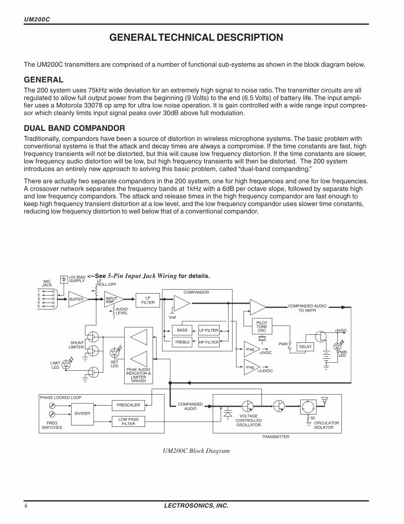
UM200C
GENERAL TECHNICAL DESCRIPTION
The UM200C transmitters are comprised of a number of functional sub-systems as shown in the block diagram below
GENERAL The 200 system uses 75kHz wide deviation for an extremely high signal to noise ratioThe transmitter circuits are all regulated to allow full output power from the beginning (9 Volts) to the end (65 Volts) of battery life The input amplishyfier uses a Motorola 33078 op amp for ultra low noise operation It is gain controlled with a wide range input compresshysor which cleanly limits input signal peaks over 30dB above full modulation
DUAL BAND COMPANDOR Traditionally compandors have been a source of distortion in wireless microphone systems The basic problem with conventional systems is that the attack and decay times are always a compromise If the time constants are fast high frequency transients will not be distorted but this will cause low frequency distortion If the time constants are slower low frequency audio distortion will be low but high frequency transients will then be distorted The 200 system introduces an entirely new approach to solving this basic problem called ldquodual-band compandingrdquo
There are actually two separate compandors in the 200 system one for high frequencies and one for low frequencies A crossover network separates the frequency bands at 1kHz with a 6dB per octave slope followed by separate high and low frequency compandors The attack and release times in the high frequency compandor are fast enough to keep high frequency transient distortion at a low level and the low frequency compandor uses slower time constants reducing low frequency distortion to well below that of a conventional compandor
Vref
BASS
TREBLE
LP FILTER
HP FILTER
SET LED
LIMIT LED
COMPANDOR
Vreg
Vreg
+5VDC
+36VDC
SHUNT LIMITER
INPUT AMP
AUDIO LEVEL
LP FILTER
PEAK AUDIO INDICATOR amp
LIMITER DRIVER
PILOT TONE OSC
5 4 3 2 1
MIC JACK
+5V BIAS SUPPLY LF
ROLL-OFF
COMPANDED AUDIO TO XMTR
COMPANDED AUDIO
PHASE LOCKED LOOP
FREQ SWITCHES
DIVIDER
LOW PASS FILTER
PRESCALER
BUFFER
PWR DELAY
+9VDC
PWR LED
VOLTAGE CONTROLLED OSCILLATOR
50 CIRCULATOR ISOLATOR
lt--See 5-Pin Input Jack Wiring for details
TRANSMITTER
UM200C Block Diagram
LECTROSONICS INC 4
Frequency Agile UHF Belt-Pack Transmitter
NO PRE-EMPHASISDE-EMPHASIS The signal to noise ratio of the 200 system is high enough to preclude the need for conventional pre-emphasis (HF boost) in the transmitter and de-emphasis (HF roll off) in the receiver Pre-emphasis and de-emphasis in an FM radio system usually provides about a 10dB improvement in the signal to noise ratio of the system but the high frequency boost in the transmitter must be removed in a purely complementary manner or else the frequency response of the original audio signal will be altered
Pre-emphasis can also cause distortion in the receiver As this signal is passed through the IF filters in the receiver distortion can be produced most noticeable at full modulation De-emphasis cannot be applied until the signal is converted into audio so there is no way around this problem short of eliminating pre-emphasis altogether Neither of these problems occur in the 200 system The dual-band compandor in the 200 Series system essentially provides a dynamic pre-emphasisde-emphasis function with extremely low distortion
PILOT TONE SQUELCH The 200 system utilizes an ultrasonic tone modulation of the carrier to operate the receiver squelch This ldquopilot tonerdquo consists of a 32kHz signal mixed with the audio signal following the microphone preamp just after the compandor to control the audio output muting of the receiver The pilot tone is filtered out of the audio signal immediately after the detector in the receiver so that it does not influence the compandor or various gain stages The basic benefit of the pilot tone squelch system is that the receiver will remain muted until it receives the pilot tone from the matching transmitter even if a strong RF signal is present on the carrier frequency of the system This is extremely important in applications that include an automatic microphone mixer
WIDE-BAND DEVIATION plusmn75kHz deviation improves the capture ratio signal to noise ratio and AM rejection of a wireless system dramatically compared to the more commonly used plusmn15kHz deviation
LONG BATTERY LIFE High efficiency circuits throughout the design allow over 45 hours of operation using a single 9 Volt alkaline battery (A 9V lithium battery will provide over 14 hours of operation) The battery compartment is a unique mechanical design which automatically adjusts to fit any brand of battery The battery contacts are spring loaded to prevent ldquorattlerdquo as the unit is handled
FREQUENCY AGILITY The transmitter section uses a synthesized frequency selectable main oscillator The frequency is extremely stable over a wide temperature range and over time
Two rotary switches located on the side panel of the unit provide 256 frequencies in 100kHz steps over a 255MHz range This alleviates carrier interference problems in mobile or travelling applications
ANTENNA At UHF frequencies where wavelengths and antennas are shorter than at VHF frequencies a resonant length wire is preferred over using the microphone cable as the antenna The antenna on the UM200C consists of a flexible 14 wavelength bronze cable detachable via an SMA connector The impedance of this connector is 50 Ohms
Rio Rancho NM ndash USA 5
UM200C
CONTROLS AND FUNCTIONS
ANTENNA
OFF ON
ndash20
0
LECTROSONICS
LEVEL AUDIO
UM200C
ADJUST
FREQUENCY 16M 100K
0
1 2
3 4 5
6 789
A B C D
E F
0
1 2
3 4 5
6 789
A B C D
E F
LF ROLL OFF 35 150
75 Hz
FREQUENCY ADJUST
LF ROLL-OFF
INPUT JACK The input on the UM200C accommodates virtually every lavalier hand-held or shotgun microphone available Line level signals can also be accommodated Use a Switchcraft TA5F connector on the cord See the separate sheet titled ldquoTransmitter 5-Pin Input Jack Wiringrdquo regarding the correct connections for various microphones and other sources
ONOFF SWITCH Turns the battery power on and off Even when the switch is turned off or on abruptly the pilot tone muting system prevents ldquothumpsrdquo or transients from occurring
ldquoONrdquo LAMP Glows brightly when the battery is good and the ONOFF switch is ON A weak or dim lamp means that the battery is weak When the light goes out there is about 15 to 30 minutes of operation left If the lamp fails to light the battery should be replaced
The ldquoONrdquo lamp is connected to a precision battery test circuit that continuously monitors battery voltage The LED is at full brightness with a new 9 Volt alkaline battery As the battery voltage drops during use the LED brightness will also decrease After about 45 hours of operation the battery voltage will be about 65 Volts and the LED will be completely out
FREQUENCY ADJUST These two rotary switches adjust the center frequency of the carrier The 16M is a coarse adjustment and the 100K is the fine adjustment Each transmitter is factory aligned at the center of its operating range The default position of the frequency select switches is in the center of the transmitterrsquos range
0 1 2
3 4 5
6 789
A B C D
E F 0 1
2 3 4 5
6 789
A B C D
E F
LECTROSONICS INC 6
Frequency Agile UHF Belt-Pack Transmitter
Since the internal circuits are all tightly regulated and the RF output stage has a separate discrete regulator the transmitter will continue to operate to a battery voltage of 65 Volts From 65 Volts to 6 Volts the transmitter will still operate but with degraded performance Please note that a weak battery will sometimes light the POWER LED immediately after turn on but will soon discharge to the point where the LED will go out just like a flashlight with ldquodeadrdquo batteries
The combination of an accurate battery condition indicator and regulation of all internal circuits provides much longer battery life as well as consistent performance over the life of the battery
MODULATION LEDS Indicate the proper setting of the MIC LEVEL control
ldquo-20rdquo LED -- Flickers or glows when sufficient audio is present
ldquo0rdquo LED -- Lights up when the input level is high enough to cause limiting The input limiter has a very high overload threshold (over 30 dB) Generally speaking some limiting is desirable in normal operation to improve the signal to noise ratio of the system The limiting action is not audible and does not create distorshytion A highly trained ear would hear only the compression of the peaks in the audio signal which is desirshyable with most tape recorders and many sound reinforcement systems
AUDIO LEVEL Used to adjust the audio input level for the proper modulation
ANTENNA The flexible wire antenna supplied with the transmitter is cut to 14 wavelength of the center of the frequency block (the frequency range) of the transmitter It is removable via an SMA connector The SMA connector is a 50 Ohm RF port which can also be connected directly to test equipment Replacement antennas are available in pre-cut lengths for specific frequency blocks or as a kit with instructions to cut the antenna for any frequency block
ADJUSTABLE LOW FREQUENCY ROLL-OFF A 18dB per octave low frequency roll-off is provided in the audio section with the -3dB point adjustable from 35Hz to 150Hz The actual roll-off frequency will vary somewhat according to the low frequency response of the mic capsule being used
The low frequency roll-off control is used to prevent undesirable subsonic (or very low frequency) audio often proshyduced by air conditioning systems automobile traffic and other sources from causing the compandor to mistrack Excessive low frequency content in the audio input can cause ldquopumping and breathingrdquo of background noise or modulation of the program audio in recording applications In sound reinforcement systems excessive low frequency content can cause excessive power amplifier drain or even damage to loudspeaker systems By rotating the control clockwise the hinge point of the roll-off is increased to reduce the level of low frequencies In controlled situations such as a motion picture production set indoors where environmental noise is minimal the control can be rotated counter-clockwise to permit low frequency audio to be captured
THE BELT CLIP The belt clip may be removed for special applications by removing one screw
USE ONLY THE SCREW THAT IS SUPPLIED
The circuitry is tightly packed into this unit A longer screw will permanently damage the transmitter Use only Lectrosonics PN28528 which is a Phillips head 4-40 x 316 FL100 screw
Rio Rancho NM ndash USA 7
UM200C
BATTERY INSTALLATION
The transmitter is powered by a standard alkaline or lithium 9 Volt battery It is important that you use ONLY an ALKALINE or LITHIUM battery for longest life Standard zinc-carbon batteries marked ldquoheavy-dutyrdquo or ldquolongshylastingrdquo are not adequate Ni-cad rechargeable batteries will only provide 15 hours of operation or less and will run down quite abruptly Alkaline batteries provide over 45 hours of operation Lithium batteries can be used to provide up to 14 hours Care should be taken not to leave a fully discharged lithium battery in the transmitter as swelling of the battery can make it difficult to remove from the compartment The battery status circuitry is designed for the voltage drop over the life of alkaline batteries
To open the battery compartment press outward on the cover door in the direction of the arrow as shown in the drawing Only firm sliding pressure is needed to open and close the battery door Swing the door open and take note of the polarity marked inside showing the location of the positive (+) and negative (-) terminals You can see the large and small contact holes inside the battery compartment with the door open
Swing the door openPress outward on the
battery door in this direction
Insert the battery correctly and close the cover by pressing the door closed and across reversing the opening proceshydure illustrated above If the battery is inserted incorrectly the door will not close Do not force the door closed
OPERATING INSTRUCTIONS
1) Install a fresh battery according to the instructions above
2) Insert the microphone plug into the input jack aligning the pins be sure that the connector locks in
3) Attach the antenna to the SMA connector on the top of the transmitter
4) Mute the sound system
5) Turn the transmitter power switch to the ldquoONrdquo position
6) Position the microphone in the location you will use in actual operation
LECTROSONICS INC 8
Frequency Agile UHF Belt-Pack Transmitter
7) While speaking or singing at the same voice level that will actually be used observe the MODULATION LEDs Adjust the AUDIO LEVEL control knob until the LEDs begin to light Start at a low setting where neither LED lights as you speak Gradually turn the gain up until one LED lights then the other
The -20 LED lights when the audio level is about 12dB below full modulation The ldquo0rdquo LED lights when the limiter begins to operate There is over 30dB of limiting range without overload above the ldquo0rdquo LED so it is desirable that the it lights up occasionally during use
8) Once the gain has been adjusted the audio system audio can be turned on to make level adjustments Set the power switch to the ON position and adjust the receiver andor sound system level as required Please note there will be a delay between the moment the switch is thrown and the time when audio will actually appear at the receiver output This intentional delay eliminates turn on thumps and is controlled by the pilot tone squelch control
OPERATING NOTES
The AUDIO LEVEL control knob should not be used to control the volume of your sound system or recorder levels This gain adjustment matches the transmitter gain with the userrsquos voice level and microphone positioning
If the audio level is too high mdash both LEDs will light frequently or stay lit This condition may reduce the dynamic range of the audio signal
If the audio level is too low mdash neither LED will light or the -20 LED will light dimly This condition may cause hiss and noise in the audio or pumping and breating in the background noise
The first LED turns on 12dB below full deviation The ldquo0rdquo LED turns on at full deviation and indicates that the input shunt compressor is operating The input limiter will handle peaks over 30dB above full modulation regardless of the gain control setting The limiter uses a true absolute value circuit to detect both positive and negative peaks The attack time is 5 milliseconds and the release time is 200 milliseconds Occasional limiting is desirable indicating that the gain is correctly set and the transmitter is fully modulated for optimum signal to noise ratio
Different voices will usually require different settings of the AUDIO LEVEL control so check this adjustment as each new person uses the system If several different people will be using the transmitter and there is not time to make the adjustment for each individual adjust it for the loudest voice
ADJUSTING THE TRANSMITTER FREQUENCY If you are experiencing interference from another signal on your frequency you may want to change the operating frequency of your system The left switch changes the operating frequency by 16 MHz per step and the right switch changes it 100 kHz per step If you are experiencing interference change the operating frequency in 100 kHz steps to find a clear channel If it is not possible to find a clear channel using the 100 kHz switch return it to its original position and change the 16 MHz switch by one click then try the 100 kHz switch again
To gain access to these switches slide the access door sideways with a fingernail
Note With the UDR200A receiver these switches also appear on the front panel of the receiver Normally you should set the transmitter switches to match the receiver switch settings
0 1 2
3 4 5
6 789
A B C D
E F 0 1
2 3 4 5
6 789
A B C D
E F
With the UDR200B receiver the front panel LED character display will indicate the correct transmitter switch settings
Rio Rancho NM ndash USA 9
UM200C
MICROPHONE CORD TERMINATION
1
2 3
45
VIEW FROM SOLDER SIDE OF PINS
03
015 Heatshrink Tubing
TA5F Connector Assembly
Mic Cord Stripping Instructions
Caution Do not allow the shield wire to touch any metal part of the connector shell The shield wire is the antenna on VHF models and poor operating range will result
Shield Wire
Crimp Tabs
Rubber InsulationCrimp
TabsRubber Insulation
NoteThis termination is required on VHF transmitters and will still work fine on UHF transmitters
LECTROSONICS INC 10
Frequency Agile UHF Belt-Pack Transmitter
5-PIN INPUT JACK WIRING
The wiring diagrams shown on the next page represent the basic wiring necessary for the most common types of microphones and other audio inputs Some microphones may require extra jumpers or a slight variation on the diashygrams shown
Caution - When wiring the connector do not use the connector body for any electrical connections A common mistake is to use the connector body as an audio ground The connector body is
already used as an RF ground on VHF models and no other use is permitted
Itrsquos virtually impossible to keep completely up to date on changes that other manufacturers make to their products It is possible that you may encounter a microphone that differs from these instructions If this occurs please call our toll-free number listed on page 13 of this instruction manual Our service department can answer your questions regarding microphone compatibility
When used on a wireless transmitter the microphone element is in the proximity of the RF coming from the transmitter The nature of electret microphones makes them sensitive to RF which can cause problems with the microphone transmitter compatibility If the electret microphone is not designed properly for use with wireless transmitters it may be necessary to install a chip capacitor in the mic capsule or connector to block the RF from entering the electret capsule This modification is shown on the next page
FB
10k
1k5
100 4
3
2
1
+
POS BIAS (OR GND)
MIC
SOURCE LOAD
LINE IN
NEG GND (OR BIAS) +
1k
10uF330pF
330pF
330pF
330pF
4 3
21 5
LECTROSONICS 5V Mic Bias
To Mic Amp
Input Jack Input Circuit
VHF transmitters use the shield of the microphone cord as the antenna The UM200C uses a 14 wave flexible wire to radiate the RF signal There is really not much difference between these two approaches with respect to the effect of the RF on the microphone capsule Even in transmitters that utilize a ldquodangling wirerdquo the microphone is still part of the ldquoground planerdquo and is therefore still in the antenna circuit
PIN 1 Shield (ground) for positive biased electret lavalier microphones Bias voltage source for negative biased electret lavalier microphones Shield (ground) for dynamic microphones and line level inputs
PIN 2 Shield (ground) for negative biased electret lavalier microphones Bias voltage source for positive biased electret lavalier microphones
PIN 3 Low impedance microphone level input for dynamic microphones Also accepts hand-held electret microshyphones provided the microphone has its own built-in battery
PIN 4 1K Ohm source load for non-Lectrosonics electret microphones Use in conjunction with other pins to provide attenuation of high level input signals
PIN 5 High impedance line level input for tape decks mixer outputs musical instruments etc
Rio Rancho NM ndash USA 11
UM200C
RF BYPASSING 2 WIRE MIC 3 WIRE MIC
Some mics require RF protection to keep the radio signal from affecting the capsule even though the transmitter input circuitry is already RF bypassed (see schematic diagram)
If the mic is wired as directed and you are having difficulty with squealing high noise or poor frequency response RF is likely to be the cause
The best RF protection is accomplished by installing RF bypass capacitors at the mic capsule If this is not possible or if you are still having problems capacitors can be installed on the mic wires inside the TA5F connector housing
Install the capacitors as follows Use 330 pF capacitors Capacitors are available from Lectrosonics Please specify the part number for the desired lead style
Leaded capacitors PN 15117 Leadless capacitors PN SCC330P
All Lectrosonics lavalier mics are already bypassed and do not need any additional capacitors installed for proper operation
BODY GROUND Caution - When wiring the connector do not use the connector body for any electrical connections A common mistake is to use the connector body as an audio ground The connector body is already used as an RF ground on VHF models and no other use is permitted
LINE LEVEL SIGNALS The normal hookup for line level signals is Signal Hot to pin 5 Signal Gnd to pin 1 pin 4 jumped to pin 1 and pin 3 jumped to pin 1 This gives a 40dB attenuator that allows signal levels much higher than 3V to be applied without limiting
If more headroom is needed insert a 100k resistor in series with pin 5 Put this resistor inside the TA5F connector to minimize noise pickup
If lower than normal line levels (less than 1V) are expected use this hookup Signal Hot to pin 5 Signal Gnd to pin 1 and pin 4 jumpered to pin 1 This provides a 20dB attenuator allowing signals as high as 3V to be applied without limiting
WIRING HOOKUPS FOR DIFFERENT SOURCES
CAPSULE CAPSULE
SHIELD
AUDIO
SHIELD
AUDIO
BIAS TA5F
CONNECTOR TA5F
CONNECTOR
Preferred locations for bypass capacitors
Alternate locations for bypass capacitors
PIN
123
4 5
PIN SHIELD 11
AUDIO 22
2 WIRE ELECTRET MIC3 WIRE ELECTRET MIC 3
POSITIVE BIAS 3
NEGATIVE BIAS
1 23
4 5
44 TA5F 5
TA5F 5 PLUGPLUG
SHIELD
AUDIO
BIAS
SLEEVEPIN PINSHIELD SHIELD 1
TIP
1 2 2AUDIOAUDIO2 WIRE ELECTRET MIC 3 3POSITIVE BIAS 4
123
4 5
LINE LEVEL
1 23
4 5
4TA5F TA5FRCA or 14 PLUG 5 PLUG 5 PLUG(See notes on lsquoLINE LEVEL SIGNALSrdquo above)
3
12 PINPIN PIN
Dynamic LO Z mic or electret with manufacturers power supply
SHIELD 1 11 2 22
3 33
1 23
4 5
44
123
4 5
DYNAMIC TA5FTA5F MIC LEVEL 55 PLUGPLUG
SHIELD
BIAS
AUDIO 3 WIRE ELECTRET MIC
NEGATIVE BIAS
LECTROSONICS INC 12
Frequency Agile UHF Belt-Pack Transmitter
TROUBLESHOOTING
Before going through the following chart be sure that you have a good battery in the transmitter It is important that you follow these steps in the sequence listed
SYMPTOM POSSIBLE CAUSE
TRANSMITTER BATTERY LED OFF 1) Battery is inserted backwards 2) Battery is dead
NO TRANSMITTER MODULATION LEDs 1) Gain control turned all the way down 2) Battery is in backwards Check power LED 3) Mic capsule is damaged or malfunctioning 4) Mic cable damaged or mis-wired
RECEIVER RF LAMP OFF 1) Transmitter not turned on 2) Transmitter battery is dead 3) Receiver antenna missing or improperly positioned 4) Transmitter and receiver not on same frequency Check
switchesdisplay on transmitter and receiver 5) Operating range is too great 6) Transmitter antenna not connected
NO SOUND (OR LOW SOUND LEVEL) RECEIVER MOD LEVEL LEDs ARE ON 1) Receiver output level set too low
2) Receiver output is disconnected cable is defective or mis-wired
3) Sound system or recorder input is turned down
DISTORTED SOUND 1) Transmitter gain (audio level) is far too high Check mod level lamps on transmitter and receiver as it is being used (refer to pages 89 for details on gain adjustment)
2) Receiver output may be mis-matched with the sound system or recorder input Adjust output level on receiver to the correct level for the recorder mixer or sound system
3) Excessive wind noise or breath ldquopopsrdquo Re-position microphone andor use a larger windscreen
4) Transmitter is not set to same frequency as receiver Check that frequency select switches on receiver and transmitter match
HISS AND NOISE -- AUDIBLE DROPOUTS 1) Transmitter gain (audio level) far too low 2) Receiver antenna missing or obstructed 3) Transmitter antenna missing 4) Operating range too great
EXCESSIVE FEEDBACK 1) Transmitter gain (audio level) too high Check gain adjustment andor reduce receiver output level
2) Transmitter too close to speaker system 3) Mic is too far from userrsquos mouth
Rio Rancho NM ndash USA 13
UM200C
SPECIFICATIONS AND FEATURES
Operating frequencies 537600 to 607900 MHz 614100 to 767900 MHz
Frequency selection 256 frequencies in 100kHz steps
RF Power output 100 mW (nominal)
Pilot tone 32764 kHz (plusmn 2Hz) 5kHz deviation
Frequency stability plusmn 0002
Deviation plusmn 75 kHz (max)
Spurious radiation 90 dB below carrier
Equivalent input noise ndash126 dBV
Input level Nominal 2 mV to 300 mV before limiting Greater than 50V maximum with limiting
Input impedance Taps provided for 500 1k 10k Ohm
Input compressor Soft compressor gt30 dB range
Gain control range 43 dB semi-log rotary control
Modulation indicators Dual LEDs indicate modulation level 12dB below limiting and at the onset of limiting
Low frequency roll-off adjustment ndash18dBoctave 35Hz to 150Hz
Controls 2 position ldquoOFF-ONrdquo slide switch for noiseless turn onturn off operation Front panel knob adjusts audio gain Recessed control on side panel
adjusts low frequency rolloff Rotary switches on side panel adjust transmitter frequency
Audio Input Jack Switchcraft 5 pin locking (TA5F)
Antenna Detachable flexible wire supplied 50 Ohm port allows connection to test equipment
Battery Precision compartment auto-adjusts to accept any known alkaline 9 Volt battery (Wersquove tried 125 different ones)
Battery Life 45 hours (alkaline) 14 hours (lithium)
Weight 63 ozs including battery
Dimensions 31 x 24 x 75 inches
Emission Designator 180KF3E
Specifications subject to change without notice
LECTROSONICS INC 14
Frequency Agile UHF Belt-Pack Transmitter
SERVICE AND REPAIR
If your system malfunctions you should attempt to correct or isolate the trouble before concluding that the equipment needs repair Make sure you have followed the setup procedure and operating instructions Check out the interconshynecting cords and then go through the TROUBLESHOOTING section in the manual
We strongly recommend that you do not try to repair the equipment yourself and do not have the local repair shop attempt anything other than the simplest repair If the repair is more complicated than a broken wire or loose connecshytion send the unit to the factory for repair and service Donrsquot attempt to adjust any controls inside the units Once set at the factory the various controls and trimmers do not drift with age or vibration and never require readjustment There are no adjustments inside that will make a malfunctioning unit start working
LECTROSONICS service department is equipped and staffed to quickly repair your equipment In-warranty repairs are made at no charge in accordance with the terms of the warranty Out-of-warranty repairs are charged at a modest flat rate plus parts and shipping Since it takes almost as much time and effort to determine what is wrong as it does to make the repair there is a charge for an exact quotation We will be happy to quote approximate charges by phone for out-of-warranty repairs
RETURNING UNITS FOR REPAIR You will save yourself time and trouble if you will follow the steps below
A DO NOT return equipment to the factory for repair without first contacting us by letter or by phone We need to know the nature of the problem the model number and the serial number of the equipment We also need a phone number where you can be reached 8 am to 4 pm (Mountain Standard Time)
B After receiving your request we will issue you a return authorization number (RA) This number will help speed your repair through our receiving and repair departments The return authorization number must be clearly shown on the outside of the shipping container
C Pack the equipment carefully and ship to us shipping costs prepaid If necessary we can provide you with the proper packing materials UPS is usually the best way to ship the units Heavy units should be ldquodouble-boxedrdquo for safe transport
D We also strongly recommend that you insure the equipment since we cannot be responsible for loss of or damage to equipment that you ship Of course we insure the equipment when we ship it back to you
Mailing address Shipping address Lectrosonics Inc Lectrosonics Inc PO Box 15900 581 Laser Rd Rio Rancho NM 87174 Rio Rancho NM 87124 USA USA
Telephones Regular (505) 892-4501 Toll Free (800) 821-1121 FAX (505) 892-6243
World Wide Web httpwwwlectrosonicscom Email saleslectrosonicscom
Rio Rancho NM ndash USA 15
LIMITED ONE YEAR WARRANTY
The equipment is warranted for one year from date of purchase against defects in materials or workmanship provided it was purchased from an authorized dealer This warranty does not cover equipment which has been abused or damaged by careless handling or shipping This warranty does not apply to used or demonstrator equipment
Should any defect develop Lectrosonics Inc will at our option repair or replace any defective parts without charge for either parts or labor If Lectrosonics Inc cannot correct the defect in your equipment it will be replaced at no charge with a similar new item Lectrosonics Inc will pay for the cost of returning your equipment to you
This warranty applies only to items returned to Lectrosonics Inc or an authorized dealer shipping costs prepaid within one year from the date of purchase
This Limited Warranty is governed by the laws of the State of New Mexico It states the entire liablility of Lectrosonics Inc and the entire remedy of the purchaser for any breach of warranty as outlined above NEITHER LECTROSONICS INC NOR ANYONE INVOLVED IN THE PRODUCTION OR DELIVERY OF THE EQUIPMENT SHALL BE LIABLE FOR ANY INDIRECT SPECIAL PUNITIVE CONSEQUENTIAL OR INCIDENTAL DAMAGES ARISING OUT OF THE USE OR INABILITY TO USE THIS EQUIPMENT EVEN IF LECTROSONICS INC HAS BEEN ADVISED OF THE POSSIBILITY OF SUCH DAMAGES IN NO EVENT SHALL THE LIABILITY OF LECTROSONICS INC EXCEED THE PURCHASE PRICE OF ANY DEFECTIVE EQUIPMENT
This warranty gives you specific legal rights You may have additional legal rights which vary from state to state
LIMITED ONE YEAR WARRANTY
LECTROSONICS INC
581 LASER ROAD RIO RANCHO NM 87124 USA wwwlectrosonicscom
November 5 2003
Frequency Agile UHF Belt-Pack Transmitter
NO PRE-EMPHASISDE-EMPHASIS The signal to noise ratio of the 200 system is high enough to preclude the need for conventional pre-emphasis (HF boost) in the transmitter and de-emphasis (HF roll off) in the receiver Pre-emphasis and de-emphasis in an FM radio system usually provides about a 10dB improvement in the signal to noise ratio of the system but the high frequency boost in the transmitter must be removed in a purely complementary manner or else the frequency response of the original audio signal will be altered
Pre-emphasis can also cause distortion in the receiver As this signal is passed through the IF filters in the receiver distortion can be produced most noticeable at full modulation De-emphasis cannot be applied until the signal is converted into audio so there is no way around this problem short of eliminating pre-emphasis altogether Neither of these problems occur in the 200 system The dual-band compandor in the 200 Series system essentially provides a dynamic pre-emphasisde-emphasis function with extremely low distortion
PILOT TONE SQUELCH The 200 system utilizes an ultrasonic tone modulation of the carrier to operate the receiver squelch This ldquopilot tonerdquo consists of a 32kHz signal mixed with the audio signal following the microphone preamp just after the compandor to control the audio output muting of the receiver The pilot tone is filtered out of the audio signal immediately after the detector in the receiver so that it does not influence the compandor or various gain stages The basic benefit of the pilot tone squelch system is that the receiver will remain muted until it receives the pilot tone from the matching transmitter even if a strong RF signal is present on the carrier frequency of the system This is extremely important in applications that include an automatic microphone mixer
WIDE-BAND DEVIATION plusmn75kHz deviation improves the capture ratio signal to noise ratio and AM rejection of a wireless system dramatically compared to the more commonly used plusmn15kHz deviation
LONG BATTERY LIFE High efficiency circuits throughout the design allow over 45 hours of operation using a single 9 Volt alkaline battery (A 9V lithium battery will provide over 14 hours of operation) The battery compartment is a unique mechanical design which automatically adjusts to fit any brand of battery The battery contacts are spring loaded to prevent ldquorattlerdquo as the unit is handled
FREQUENCY AGILITY The transmitter section uses a synthesized frequency selectable main oscillator The frequency is extremely stable over a wide temperature range and over time
Two rotary switches located on the side panel of the unit provide 256 frequencies in 100kHz steps over a 255MHz range This alleviates carrier interference problems in mobile or travelling applications
ANTENNA At UHF frequencies where wavelengths and antennas are shorter than at VHF frequencies a resonant length wire is preferred over using the microphone cable as the antenna The antenna on the UM200C consists of a flexible 14 wavelength bronze cable detachable via an SMA connector The impedance of this connector is 50 Ohms
Rio Rancho NM ndash USA 5
UM200C
CONTROLS AND FUNCTIONS
ANTENNA
OFF ON
ndash20
0
LECTROSONICS
LEVEL AUDIO
UM200C
ADJUST
FREQUENCY 16M 100K
0
1 2
3 4 5
6 789
A B C D
E F
0
1 2
3 4 5
6 789
A B C D
E F
LF ROLL OFF 35 150
75 Hz
FREQUENCY ADJUST
LF ROLL-OFF
INPUT JACK The input on the UM200C accommodates virtually every lavalier hand-held or shotgun microphone available Line level signals can also be accommodated Use a Switchcraft TA5F connector on the cord See the separate sheet titled ldquoTransmitter 5-Pin Input Jack Wiringrdquo regarding the correct connections for various microphones and other sources
ONOFF SWITCH Turns the battery power on and off Even when the switch is turned off or on abruptly the pilot tone muting system prevents ldquothumpsrdquo or transients from occurring
ldquoONrdquo LAMP Glows brightly when the battery is good and the ONOFF switch is ON A weak or dim lamp means that the battery is weak When the light goes out there is about 15 to 30 minutes of operation left If the lamp fails to light the battery should be replaced
The ldquoONrdquo lamp is connected to a precision battery test circuit that continuously monitors battery voltage The LED is at full brightness with a new 9 Volt alkaline battery As the battery voltage drops during use the LED brightness will also decrease After about 45 hours of operation the battery voltage will be about 65 Volts and the LED will be completely out
FREQUENCY ADJUST These two rotary switches adjust the center frequency of the carrier The 16M is a coarse adjustment and the 100K is the fine adjustment Each transmitter is factory aligned at the center of its operating range The default position of the frequency select switches is in the center of the transmitterrsquos range
0 1 2
3 4 5
6 789
A B C D
E F 0 1
2 3 4 5
6 789
A B C D
E F
LECTROSONICS INC 6
Frequency Agile UHF Belt-Pack Transmitter
Since the internal circuits are all tightly regulated and the RF output stage has a separate discrete regulator the transmitter will continue to operate to a battery voltage of 65 Volts From 65 Volts to 6 Volts the transmitter will still operate but with degraded performance Please note that a weak battery will sometimes light the POWER LED immediately after turn on but will soon discharge to the point where the LED will go out just like a flashlight with ldquodeadrdquo batteries
The combination of an accurate battery condition indicator and regulation of all internal circuits provides much longer battery life as well as consistent performance over the life of the battery
MODULATION LEDS Indicate the proper setting of the MIC LEVEL control
ldquo-20rdquo LED -- Flickers or glows when sufficient audio is present
ldquo0rdquo LED -- Lights up when the input level is high enough to cause limiting The input limiter has a very high overload threshold (over 30 dB) Generally speaking some limiting is desirable in normal operation to improve the signal to noise ratio of the system The limiting action is not audible and does not create distorshytion A highly trained ear would hear only the compression of the peaks in the audio signal which is desirshyable with most tape recorders and many sound reinforcement systems
AUDIO LEVEL Used to adjust the audio input level for the proper modulation
ANTENNA The flexible wire antenna supplied with the transmitter is cut to 14 wavelength of the center of the frequency block (the frequency range) of the transmitter It is removable via an SMA connector The SMA connector is a 50 Ohm RF port which can also be connected directly to test equipment Replacement antennas are available in pre-cut lengths for specific frequency blocks or as a kit with instructions to cut the antenna for any frequency block
ADJUSTABLE LOW FREQUENCY ROLL-OFF A 18dB per octave low frequency roll-off is provided in the audio section with the -3dB point adjustable from 35Hz to 150Hz The actual roll-off frequency will vary somewhat according to the low frequency response of the mic capsule being used
The low frequency roll-off control is used to prevent undesirable subsonic (or very low frequency) audio often proshyduced by air conditioning systems automobile traffic and other sources from causing the compandor to mistrack Excessive low frequency content in the audio input can cause ldquopumping and breathingrdquo of background noise or modulation of the program audio in recording applications In sound reinforcement systems excessive low frequency content can cause excessive power amplifier drain or even damage to loudspeaker systems By rotating the control clockwise the hinge point of the roll-off is increased to reduce the level of low frequencies In controlled situations such as a motion picture production set indoors where environmental noise is minimal the control can be rotated counter-clockwise to permit low frequency audio to be captured
THE BELT CLIP The belt clip may be removed for special applications by removing one screw
USE ONLY THE SCREW THAT IS SUPPLIED
The circuitry is tightly packed into this unit A longer screw will permanently damage the transmitter Use only Lectrosonics PN28528 which is a Phillips head 4-40 x 316 FL100 screw
Rio Rancho NM ndash USA 7
UM200C
BATTERY INSTALLATION
The transmitter is powered by a standard alkaline or lithium 9 Volt battery It is important that you use ONLY an ALKALINE or LITHIUM battery for longest life Standard zinc-carbon batteries marked ldquoheavy-dutyrdquo or ldquolongshylastingrdquo are not adequate Ni-cad rechargeable batteries will only provide 15 hours of operation or less and will run down quite abruptly Alkaline batteries provide over 45 hours of operation Lithium batteries can be used to provide up to 14 hours Care should be taken not to leave a fully discharged lithium battery in the transmitter as swelling of the battery can make it difficult to remove from the compartment The battery status circuitry is designed for the voltage drop over the life of alkaline batteries
To open the battery compartment press outward on the cover door in the direction of the arrow as shown in the drawing Only firm sliding pressure is needed to open and close the battery door Swing the door open and take note of the polarity marked inside showing the location of the positive (+) and negative (-) terminals You can see the large and small contact holes inside the battery compartment with the door open
Swing the door openPress outward on the
battery door in this direction
Insert the battery correctly and close the cover by pressing the door closed and across reversing the opening proceshydure illustrated above If the battery is inserted incorrectly the door will not close Do not force the door closed
OPERATING INSTRUCTIONS
1) Install a fresh battery according to the instructions above
2) Insert the microphone plug into the input jack aligning the pins be sure that the connector locks in
3) Attach the antenna to the SMA connector on the top of the transmitter
4) Mute the sound system
5) Turn the transmitter power switch to the ldquoONrdquo position
6) Position the microphone in the location you will use in actual operation
LECTROSONICS INC 8
Frequency Agile UHF Belt-Pack Transmitter
7) While speaking or singing at the same voice level that will actually be used observe the MODULATION LEDs Adjust the AUDIO LEVEL control knob until the LEDs begin to light Start at a low setting where neither LED lights as you speak Gradually turn the gain up until one LED lights then the other
The -20 LED lights when the audio level is about 12dB below full modulation The ldquo0rdquo LED lights when the limiter begins to operate There is over 30dB of limiting range without overload above the ldquo0rdquo LED so it is desirable that the it lights up occasionally during use
8) Once the gain has been adjusted the audio system audio can be turned on to make level adjustments Set the power switch to the ON position and adjust the receiver andor sound system level as required Please note there will be a delay between the moment the switch is thrown and the time when audio will actually appear at the receiver output This intentional delay eliminates turn on thumps and is controlled by the pilot tone squelch control
OPERATING NOTES
The AUDIO LEVEL control knob should not be used to control the volume of your sound system or recorder levels This gain adjustment matches the transmitter gain with the userrsquos voice level and microphone positioning
If the audio level is too high mdash both LEDs will light frequently or stay lit This condition may reduce the dynamic range of the audio signal
If the audio level is too low mdash neither LED will light or the -20 LED will light dimly This condition may cause hiss and noise in the audio or pumping and breating in the background noise
The first LED turns on 12dB below full deviation The ldquo0rdquo LED turns on at full deviation and indicates that the input shunt compressor is operating The input limiter will handle peaks over 30dB above full modulation regardless of the gain control setting The limiter uses a true absolute value circuit to detect both positive and negative peaks The attack time is 5 milliseconds and the release time is 200 milliseconds Occasional limiting is desirable indicating that the gain is correctly set and the transmitter is fully modulated for optimum signal to noise ratio
Different voices will usually require different settings of the AUDIO LEVEL control so check this adjustment as each new person uses the system If several different people will be using the transmitter and there is not time to make the adjustment for each individual adjust it for the loudest voice
ADJUSTING THE TRANSMITTER FREQUENCY If you are experiencing interference from another signal on your frequency you may want to change the operating frequency of your system The left switch changes the operating frequency by 16 MHz per step and the right switch changes it 100 kHz per step If you are experiencing interference change the operating frequency in 100 kHz steps to find a clear channel If it is not possible to find a clear channel using the 100 kHz switch return it to its original position and change the 16 MHz switch by one click then try the 100 kHz switch again
To gain access to these switches slide the access door sideways with a fingernail
Note With the UDR200A receiver these switches also appear on the front panel of the receiver Normally you should set the transmitter switches to match the receiver switch settings
0 1 2
3 4 5
6 789
A B C D
E F 0 1
2 3 4 5
6 789
A B C D
E F
With the UDR200B receiver the front panel LED character display will indicate the correct transmitter switch settings
Rio Rancho NM ndash USA 9
UM200C
MICROPHONE CORD TERMINATION
1
2 3
45
VIEW FROM SOLDER SIDE OF PINS
03
015 Heatshrink Tubing
TA5F Connector Assembly
Mic Cord Stripping Instructions
Caution Do not allow the shield wire to touch any metal part of the connector shell The shield wire is the antenna on VHF models and poor operating range will result
Shield Wire
Crimp Tabs
Rubber InsulationCrimp
TabsRubber Insulation
NoteThis termination is required on VHF transmitters and will still work fine on UHF transmitters
LECTROSONICS INC 10
Frequency Agile UHF Belt-Pack Transmitter
5-PIN INPUT JACK WIRING
The wiring diagrams shown on the next page represent the basic wiring necessary for the most common types of microphones and other audio inputs Some microphones may require extra jumpers or a slight variation on the diashygrams shown
Caution - When wiring the connector do not use the connector body for any electrical connections A common mistake is to use the connector body as an audio ground The connector body is
already used as an RF ground on VHF models and no other use is permitted
Itrsquos virtually impossible to keep completely up to date on changes that other manufacturers make to their products It is possible that you may encounter a microphone that differs from these instructions If this occurs please call our toll-free number listed on page 13 of this instruction manual Our service department can answer your questions regarding microphone compatibility
When used on a wireless transmitter the microphone element is in the proximity of the RF coming from the transmitter The nature of electret microphones makes them sensitive to RF which can cause problems with the microphone transmitter compatibility If the electret microphone is not designed properly for use with wireless transmitters it may be necessary to install a chip capacitor in the mic capsule or connector to block the RF from entering the electret capsule This modification is shown on the next page
FB
10k
1k5
100 4
3
2
1
+
POS BIAS (OR GND)
MIC
SOURCE LOAD
LINE IN
NEG GND (OR BIAS) +
1k
10uF330pF
330pF
330pF
330pF
4 3
21 5
LECTROSONICS 5V Mic Bias
To Mic Amp
Input Jack Input Circuit
VHF transmitters use the shield of the microphone cord as the antenna The UM200C uses a 14 wave flexible wire to radiate the RF signal There is really not much difference between these two approaches with respect to the effect of the RF on the microphone capsule Even in transmitters that utilize a ldquodangling wirerdquo the microphone is still part of the ldquoground planerdquo and is therefore still in the antenna circuit
PIN 1 Shield (ground) for positive biased electret lavalier microphones Bias voltage source for negative biased electret lavalier microphones Shield (ground) for dynamic microphones and line level inputs
PIN 2 Shield (ground) for negative biased electret lavalier microphones Bias voltage source for positive biased electret lavalier microphones
PIN 3 Low impedance microphone level input for dynamic microphones Also accepts hand-held electret microshyphones provided the microphone has its own built-in battery
PIN 4 1K Ohm source load for non-Lectrosonics electret microphones Use in conjunction with other pins to provide attenuation of high level input signals
PIN 5 High impedance line level input for tape decks mixer outputs musical instruments etc
Rio Rancho NM ndash USA 11
UM200C
RF BYPASSING 2 WIRE MIC 3 WIRE MIC
Some mics require RF protection to keep the radio signal from affecting the capsule even though the transmitter input circuitry is already RF bypassed (see schematic diagram)
If the mic is wired as directed and you are having difficulty with squealing high noise or poor frequency response RF is likely to be the cause
The best RF protection is accomplished by installing RF bypass capacitors at the mic capsule If this is not possible or if you are still having problems capacitors can be installed on the mic wires inside the TA5F connector housing
Install the capacitors as follows Use 330 pF capacitors Capacitors are available from Lectrosonics Please specify the part number for the desired lead style
Leaded capacitors PN 15117 Leadless capacitors PN SCC330P
All Lectrosonics lavalier mics are already bypassed and do not need any additional capacitors installed for proper operation
BODY GROUND Caution - When wiring the connector do not use the connector body for any electrical connections A common mistake is to use the connector body as an audio ground The connector body is already used as an RF ground on VHF models and no other use is permitted
LINE LEVEL SIGNALS The normal hookup for line level signals is Signal Hot to pin 5 Signal Gnd to pin 1 pin 4 jumped to pin 1 and pin 3 jumped to pin 1 This gives a 40dB attenuator that allows signal levels much higher than 3V to be applied without limiting
If more headroom is needed insert a 100k resistor in series with pin 5 Put this resistor inside the TA5F connector to minimize noise pickup
If lower than normal line levels (less than 1V) are expected use this hookup Signal Hot to pin 5 Signal Gnd to pin 1 and pin 4 jumpered to pin 1 This provides a 20dB attenuator allowing signals as high as 3V to be applied without limiting
WIRING HOOKUPS FOR DIFFERENT SOURCES
CAPSULE CAPSULE
SHIELD
AUDIO
SHIELD
AUDIO
BIAS TA5F
CONNECTOR TA5F
CONNECTOR
Preferred locations for bypass capacitors
Alternate locations for bypass capacitors
PIN
123
4 5
PIN SHIELD 11
AUDIO 22
2 WIRE ELECTRET MIC3 WIRE ELECTRET MIC 3
POSITIVE BIAS 3
NEGATIVE BIAS
1 23
4 5
44 TA5F 5
TA5F 5 PLUGPLUG
SHIELD
AUDIO
BIAS
SLEEVEPIN PINSHIELD SHIELD 1
TIP
1 2 2AUDIOAUDIO2 WIRE ELECTRET MIC 3 3POSITIVE BIAS 4
123
4 5
LINE LEVEL
1 23
4 5
4TA5F TA5FRCA or 14 PLUG 5 PLUG 5 PLUG(See notes on lsquoLINE LEVEL SIGNALSrdquo above)
3
12 PINPIN PIN
Dynamic LO Z mic or electret with manufacturers power supply
SHIELD 1 11 2 22
3 33
1 23
4 5
44
123
4 5
DYNAMIC TA5FTA5F MIC LEVEL 55 PLUGPLUG
SHIELD
BIAS
AUDIO 3 WIRE ELECTRET MIC
NEGATIVE BIAS
LECTROSONICS INC 12
Frequency Agile UHF Belt-Pack Transmitter
TROUBLESHOOTING
Before going through the following chart be sure that you have a good battery in the transmitter It is important that you follow these steps in the sequence listed
SYMPTOM POSSIBLE CAUSE
TRANSMITTER BATTERY LED OFF 1) Battery is inserted backwards 2) Battery is dead
NO TRANSMITTER MODULATION LEDs 1) Gain control turned all the way down 2) Battery is in backwards Check power LED 3) Mic capsule is damaged or malfunctioning 4) Mic cable damaged or mis-wired
RECEIVER RF LAMP OFF 1) Transmitter not turned on 2) Transmitter battery is dead 3) Receiver antenna missing or improperly positioned 4) Transmitter and receiver not on same frequency Check
switchesdisplay on transmitter and receiver 5) Operating range is too great 6) Transmitter antenna not connected
NO SOUND (OR LOW SOUND LEVEL) RECEIVER MOD LEVEL LEDs ARE ON 1) Receiver output level set too low
2) Receiver output is disconnected cable is defective or mis-wired
3) Sound system or recorder input is turned down
DISTORTED SOUND 1) Transmitter gain (audio level) is far too high Check mod level lamps on transmitter and receiver as it is being used (refer to pages 89 for details on gain adjustment)
2) Receiver output may be mis-matched with the sound system or recorder input Adjust output level on receiver to the correct level for the recorder mixer or sound system
3) Excessive wind noise or breath ldquopopsrdquo Re-position microphone andor use a larger windscreen
4) Transmitter is not set to same frequency as receiver Check that frequency select switches on receiver and transmitter match
HISS AND NOISE -- AUDIBLE DROPOUTS 1) Transmitter gain (audio level) far too low 2) Receiver antenna missing or obstructed 3) Transmitter antenna missing 4) Operating range too great
EXCESSIVE FEEDBACK 1) Transmitter gain (audio level) too high Check gain adjustment andor reduce receiver output level
2) Transmitter too close to speaker system 3) Mic is too far from userrsquos mouth
Rio Rancho NM ndash USA 13
UM200C
SPECIFICATIONS AND FEATURES
Operating frequencies 537600 to 607900 MHz 614100 to 767900 MHz
Frequency selection 256 frequencies in 100kHz steps
RF Power output 100 mW (nominal)
Pilot tone 32764 kHz (plusmn 2Hz) 5kHz deviation
Frequency stability plusmn 0002
Deviation plusmn 75 kHz (max)
Spurious radiation 90 dB below carrier
Equivalent input noise ndash126 dBV
Input level Nominal 2 mV to 300 mV before limiting Greater than 50V maximum with limiting
Input impedance Taps provided for 500 1k 10k Ohm
Input compressor Soft compressor gt30 dB range
Gain control range 43 dB semi-log rotary control
Modulation indicators Dual LEDs indicate modulation level 12dB below limiting and at the onset of limiting
Low frequency roll-off adjustment ndash18dBoctave 35Hz to 150Hz
Controls 2 position ldquoOFF-ONrdquo slide switch for noiseless turn onturn off operation Front panel knob adjusts audio gain Recessed control on side panel
adjusts low frequency rolloff Rotary switches on side panel adjust transmitter frequency
Audio Input Jack Switchcraft 5 pin locking (TA5F)
Antenna Detachable flexible wire supplied 50 Ohm port allows connection to test equipment
Battery Precision compartment auto-adjusts to accept any known alkaline 9 Volt battery (Wersquove tried 125 different ones)
Battery Life 45 hours (alkaline) 14 hours (lithium)
Weight 63 ozs including battery
Dimensions 31 x 24 x 75 inches
Emission Designator 180KF3E
Specifications subject to change without notice
LECTROSONICS INC 14
Frequency Agile UHF Belt-Pack Transmitter
SERVICE AND REPAIR
If your system malfunctions you should attempt to correct or isolate the trouble before concluding that the equipment needs repair Make sure you have followed the setup procedure and operating instructions Check out the interconshynecting cords and then go through the TROUBLESHOOTING section in the manual
We strongly recommend that you do not try to repair the equipment yourself and do not have the local repair shop attempt anything other than the simplest repair If the repair is more complicated than a broken wire or loose connecshytion send the unit to the factory for repair and service Donrsquot attempt to adjust any controls inside the units Once set at the factory the various controls and trimmers do not drift with age or vibration and never require readjustment There are no adjustments inside that will make a malfunctioning unit start working
LECTROSONICS service department is equipped and staffed to quickly repair your equipment In-warranty repairs are made at no charge in accordance with the terms of the warranty Out-of-warranty repairs are charged at a modest flat rate plus parts and shipping Since it takes almost as much time and effort to determine what is wrong as it does to make the repair there is a charge for an exact quotation We will be happy to quote approximate charges by phone for out-of-warranty repairs
RETURNING UNITS FOR REPAIR You will save yourself time and trouble if you will follow the steps below
A DO NOT return equipment to the factory for repair without first contacting us by letter or by phone We need to know the nature of the problem the model number and the serial number of the equipment We also need a phone number where you can be reached 8 am to 4 pm (Mountain Standard Time)
B After receiving your request we will issue you a return authorization number (RA) This number will help speed your repair through our receiving and repair departments The return authorization number must be clearly shown on the outside of the shipping container
C Pack the equipment carefully and ship to us shipping costs prepaid If necessary we can provide you with the proper packing materials UPS is usually the best way to ship the units Heavy units should be ldquodouble-boxedrdquo for safe transport
D We also strongly recommend that you insure the equipment since we cannot be responsible for loss of or damage to equipment that you ship Of course we insure the equipment when we ship it back to you
Mailing address Shipping address Lectrosonics Inc Lectrosonics Inc PO Box 15900 581 Laser Rd Rio Rancho NM 87174 Rio Rancho NM 87124 USA USA
Telephones Regular (505) 892-4501 Toll Free (800) 821-1121 FAX (505) 892-6243
World Wide Web httpwwwlectrosonicscom Email saleslectrosonicscom
Rio Rancho NM ndash USA 15
LIMITED ONE YEAR WARRANTY
The equipment is warranted for one year from date of purchase against defects in materials or workmanship provided it was purchased from an authorized dealer This warranty does not cover equipment which has been abused or damaged by careless handling or shipping This warranty does not apply to used or demonstrator equipment
Should any defect develop Lectrosonics Inc will at our option repair or replace any defective parts without charge for either parts or labor If Lectrosonics Inc cannot correct the defect in your equipment it will be replaced at no charge with a similar new item Lectrosonics Inc will pay for the cost of returning your equipment to you
This warranty applies only to items returned to Lectrosonics Inc or an authorized dealer shipping costs prepaid within one year from the date of purchase
This Limited Warranty is governed by the laws of the State of New Mexico It states the entire liablility of Lectrosonics Inc and the entire remedy of the purchaser for any breach of warranty as outlined above NEITHER LECTROSONICS INC NOR ANYONE INVOLVED IN THE PRODUCTION OR DELIVERY OF THE EQUIPMENT SHALL BE LIABLE FOR ANY INDIRECT SPECIAL PUNITIVE CONSEQUENTIAL OR INCIDENTAL DAMAGES ARISING OUT OF THE USE OR INABILITY TO USE THIS EQUIPMENT EVEN IF LECTROSONICS INC HAS BEEN ADVISED OF THE POSSIBILITY OF SUCH DAMAGES IN NO EVENT SHALL THE LIABILITY OF LECTROSONICS INC EXCEED THE PURCHASE PRICE OF ANY DEFECTIVE EQUIPMENT
This warranty gives you specific legal rights You may have additional legal rights which vary from state to state
LIMITED ONE YEAR WARRANTY
LECTROSONICS INC
581 LASER ROAD RIO RANCHO NM 87124 USA wwwlectrosonicscom
November 5 2003
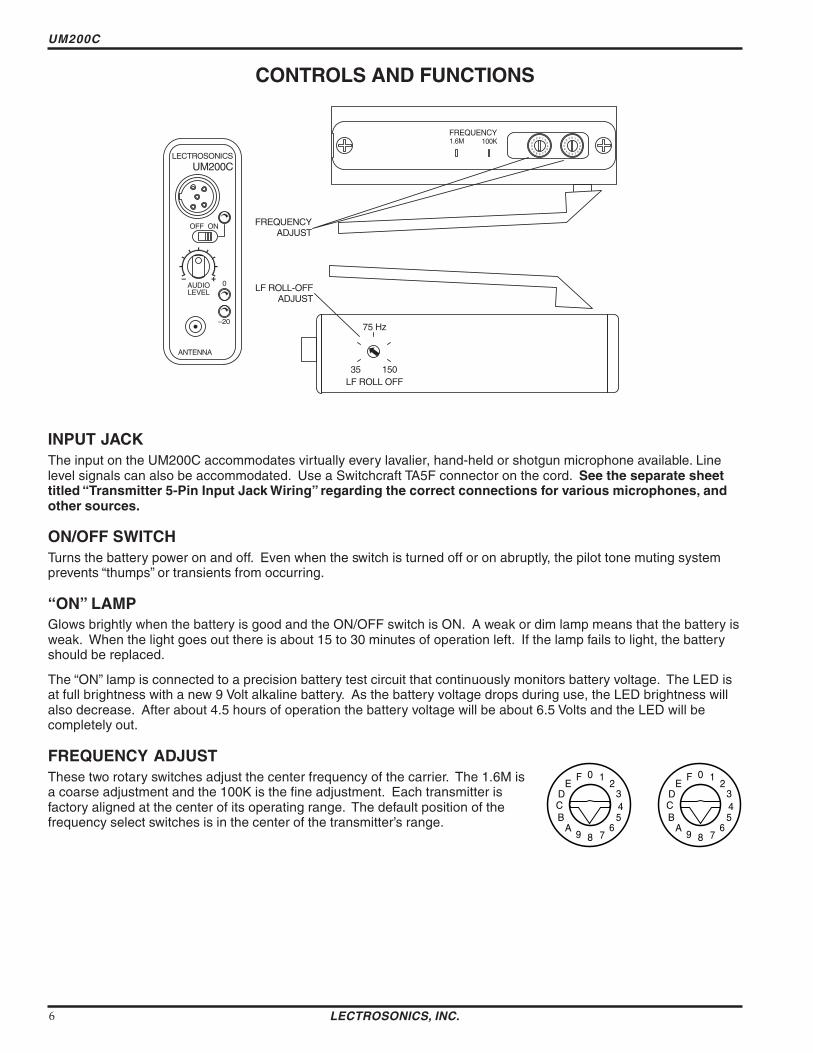
UM200C
CONTROLS AND FUNCTIONS
ANTENNA
OFF ON
ndash20
0
LECTROSONICS
LEVEL AUDIO
UM200C
ADJUST
FREQUENCY 16M 100K
0
1 2
3 4 5
6 789
A B C D
E F
0
1 2
3 4 5
6 789
A B C D
E F
LF ROLL OFF 35 150
75 Hz
FREQUENCY ADJUST
LF ROLL-OFF
INPUT JACK The input on the UM200C accommodates virtually every lavalier hand-held or shotgun microphone available Line level signals can also be accommodated Use a Switchcraft TA5F connector on the cord See the separate sheet titled ldquoTransmitter 5-Pin Input Jack Wiringrdquo regarding the correct connections for various microphones and other sources
ONOFF SWITCH Turns the battery power on and off Even when the switch is turned off or on abruptly the pilot tone muting system prevents ldquothumpsrdquo or transients from occurring
ldquoONrdquo LAMP Glows brightly when the battery is good and the ONOFF switch is ON A weak or dim lamp means that the battery is weak When the light goes out there is about 15 to 30 minutes of operation left If the lamp fails to light the battery should be replaced
The ldquoONrdquo lamp is connected to a precision battery test circuit that continuously monitors battery voltage The LED is at full brightness with a new 9 Volt alkaline battery As the battery voltage drops during use the LED brightness will also decrease After about 45 hours of operation the battery voltage will be about 65 Volts and the LED will be completely out
FREQUENCY ADJUST These two rotary switches adjust the center frequency of the carrier The 16M is a coarse adjustment and the 100K is the fine adjustment Each transmitter is factory aligned at the center of its operating range The default position of the frequency select switches is in the center of the transmitterrsquos range
0 1 2
3 4 5
6 789
A B C D
E F 0 1
2 3 4 5
6 789
A B C D
E F
LECTROSONICS INC 6
Frequency Agile UHF Belt-Pack Transmitter
Since the internal circuits are all tightly regulated and the RF output stage has a separate discrete regulator the transmitter will continue to operate to a battery voltage of 65 Volts From 65 Volts to 6 Volts the transmitter will still operate but with degraded performance Please note that a weak battery will sometimes light the POWER LED immediately after turn on but will soon discharge to the point where the LED will go out just like a flashlight with ldquodeadrdquo batteries
The combination of an accurate battery condition indicator and regulation of all internal circuits provides much longer battery life as well as consistent performance over the life of the battery
MODULATION LEDS Indicate the proper setting of the MIC LEVEL control
ldquo-20rdquo LED -- Flickers or glows when sufficient audio is present
ldquo0rdquo LED -- Lights up when the input level is high enough to cause limiting The input limiter has a very high overload threshold (over 30 dB) Generally speaking some limiting is desirable in normal operation to improve the signal to noise ratio of the system The limiting action is not audible and does not create distorshytion A highly trained ear would hear only the compression of the peaks in the audio signal which is desirshyable with most tape recorders and many sound reinforcement systems
AUDIO LEVEL Used to adjust the audio input level for the proper modulation
ANTENNA The flexible wire antenna supplied with the transmitter is cut to 14 wavelength of the center of the frequency block (the frequency range) of the transmitter It is removable via an SMA connector The SMA connector is a 50 Ohm RF port which can also be connected directly to test equipment Replacement antennas are available in pre-cut lengths for specific frequency blocks or as a kit with instructions to cut the antenna for any frequency block
ADJUSTABLE LOW FREQUENCY ROLL-OFF A 18dB per octave low frequency roll-off is provided in the audio section with the -3dB point adjustable from 35Hz to 150Hz The actual roll-off frequency will vary somewhat according to the low frequency response of the mic capsule being used
The low frequency roll-off control is used to prevent undesirable subsonic (or very low frequency) audio often proshyduced by air conditioning systems automobile traffic and other sources from causing the compandor to mistrack Excessive low frequency content in the audio input can cause ldquopumping and breathingrdquo of background noise or modulation of the program audio in recording applications In sound reinforcement systems excessive low frequency content can cause excessive power amplifier drain or even damage to loudspeaker systems By rotating the control clockwise the hinge point of the roll-off is increased to reduce the level of low frequencies In controlled situations such as a motion picture production set indoors where environmental noise is minimal the control can be rotated counter-clockwise to permit low frequency audio to be captured
THE BELT CLIP The belt clip may be removed for special applications by removing one screw
USE ONLY THE SCREW THAT IS SUPPLIED
The circuitry is tightly packed into this unit A longer screw will permanently damage the transmitter Use only Lectrosonics PN28528 which is a Phillips head 4-40 x 316 FL100 screw
Rio Rancho NM ndash USA 7
UM200C
BATTERY INSTALLATION
The transmitter is powered by a standard alkaline or lithium 9 Volt battery It is important that you use ONLY an ALKALINE or LITHIUM battery for longest life Standard zinc-carbon batteries marked ldquoheavy-dutyrdquo or ldquolongshylastingrdquo are not adequate Ni-cad rechargeable batteries will only provide 15 hours of operation or less and will run down quite abruptly Alkaline batteries provide over 45 hours of operation Lithium batteries can be used to provide up to 14 hours Care should be taken not to leave a fully discharged lithium battery in the transmitter as swelling of the battery can make it difficult to remove from the compartment The battery status circuitry is designed for the voltage drop over the life of alkaline batteries
To open the battery compartment press outward on the cover door in the direction of the arrow as shown in the drawing Only firm sliding pressure is needed to open and close the battery door Swing the door open and take note of the polarity marked inside showing the location of the positive (+) and negative (-) terminals You can see the large and small contact holes inside the battery compartment with the door open
Swing the door openPress outward on the
battery door in this direction
Insert the battery correctly and close the cover by pressing the door closed and across reversing the opening proceshydure illustrated above If the battery is inserted incorrectly the door will not close Do not force the door closed
OPERATING INSTRUCTIONS
1) Install a fresh battery according to the instructions above
2) Insert the microphone plug into the input jack aligning the pins be sure that the connector locks in
3) Attach the antenna to the SMA connector on the top of the transmitter
4) Mute the sound system
5) Turn the transmitter power switch to the ldquoONrdquo position
6) Position the microphone in the location you will use in actual operation
LECTROSONICS INC 8
Frequency Agile UHF Belt-Pack Transmitter
7) While speaking or singing at the same voice level that will actually be used observe the MODULATION LEDs Adjust the AUDIO LEVEL control knob until the LEDs begin to light Start at a low setting where neither LED lights as you speak Gradually turn the gain up until one LED lights then the other
The -20 LED lights when the audio level is about 12dB below full modulation The ldquo0rdquo LED lights when the limiter begins to operate There is over 30dB of limiting range without overload above the ldquo0rdquo LED so it is desirable that the it lights up occasionally during use
8) Once the gain has been adjusted the audio system audio can be turned on to make level adjustments Set the power switch to the ON position and adjust the receiver andor sound system level as required Please note there will be a delay between the moment the switch is thrown and the time when audio will actually appear at the receiver output This intentional delay eliminates turn on thumps and is controlled by the pilot tone squelch control
OPERATING NOTES
The AUDIO LEVEL control knob should not be used to control the volume of your sound system or recorder levels This gain adjustment matches the transmitter gain with the userrsquos voice level and microphone positioning
If the audio level is too high mdash both LEDs will light frequently or stay lit This condition may reduce the dynamic range of the audio signal
If the audio level is too low mdash neither LED will light or the -20 LED will light dimly This condition may cause hiss and noise in the audio or pumping and breating in the background noise
The first LED turns on 12dB below full deviation The ldquo0rdquo LED turns on at full deviation and indicates that the input shunt compressor is operating The input limiter will handle peaks over 30dB above full modulation regardless of the gain control setting The limiter uses a true absolute value circuit to detect both positive and negative peaks The attack time is 5 milliseconds and the release time is 200 milliseconds Occasional limiting is desirable indicating that the gain is correctly set and the transmitter is fully modulated for optimum signal to noise ratio
Different voices will usually require different settings of the AUDIO LEVEL control so check this adjustment as each new person uses the system If several different people will be using the transmitter and there is not time to make the adjustment for each individual adjust it for the loudest voice
ADJUSTING THE TRANSMITTER FREQUENCY If you are experiencing interference from another signal on your frequency you may want to change the operating frequency of your system The left switch changes the operating frequency by 16 MHz per step and the right switch changes it 100 kHz per step If you are experiencing interference change the operating frequency in 100 kHz steps to find a clear channel If it is not possible to find a clear channel using the 100 kHz switch return it to its original position and change the 16 MHz switch by one click then try the 100 kHz switch again
To gain access to these switches slide the access door sideways with a fingernail
Note With the UDR200A receiver these switches also appear on the front panel of the receiver Normally you should set the transmitter switches to match the receiver switch settings
0 1 2
3 4 5
6 789
A B C D
E F 0 1
2 3 4 5
6 789
A B C D
E F
With the UDR200B receiver the front panel LED character display will indicate the correct transmitter switch settings
Rio Rancho NM ndash USA 9
UM200C
MICROPHONE CORD TERMINATION
1
2 3
45
VIEW FROM SOLDER SIDE OF PINS
03
015 Heatshrink Tubing
TA5F Connector Assembly
Mic Cord Stripping Instructions
Caution Do not allow the shield wire to touch any metal part of the connector shell The shield wire is the antenna on VHF models and poor operating range will result
Shield Wire
Crimp Tabs
Rubber InsulationCrimp
TabsRubber Insulation
NoteThis termination is required on VHF transmitters and will still work fine on UHF transmitters
LECTROSONICS INC 10
Frequency Agile UHF Belt-Pack Transmitter
5-PIN INPUT JACK WIRING
The wiring diagrams shown on the next page represent the basic wiring necessary for the most common types of microphones and other audio inputs Some microphones may require extra jumpers or a slight variation on the diashygrams shown
Caution - When wiring the connector do not use the connector body for any electrical connections A common mistake is to use the connector body as an audio ground The connector body is
already used as an RF ground on VHF models and no other use is permitted
Itrsquos virtually impossible to keep completely up to date on changes that other manufacturers make to their products It is possible that you may encounter a microphone that differs from these instructions If this occurs please call our toll-free number listed on page 13 of this instruction manual Our service department can answer your questions regarding microphone compatibility
When used on a wireless transmitter the microphone element is in the proximity of the RF coming from the transmitter The nature of electret microphones makes them sensitive to RF which can cause problems with the microphone transmitter compatibility If the electret microphone is not designed properly for use with wireless transmitters it may be necessary to install a chip capacitor in the mic capsule or connector to block the RF from entering the electret capsule This modification is shown on the next page
FB
10k
1k5
100 4
3
2
1
+
POS BIAS (OR GND)
MIC
SOURCE LOAD
LINE IN
NEG GND (OR BIAS) +
1k
10uF330pF
330pF
330pF
330pF
4 3
21 5
LECTROSONICS 5V Mic Bias
To Mic Amp
Input Jack Input Circuit
VHF transmitters use the shield of the microphone cord as the antenna The UM200C uses a 14 wave flexible wire to radiate the RF signal There is really not much difference between these two approaches with respect to the effect of the RF on the microphone capsule Even in transmitters that utilize a ldquodangling wirerdquo the microphone is still part of the ldquoground planerdquo and is therefore still in the antenna circuit
PIN 1 Shield (ground) for positive biased electret lavalier microphones Bias voltage source for negative biased electret lavalier microphones Shield (ground) for dynamic microphones and line level inputs
PIN 2 Shield (ground) for negative biased electret lavalier microphones Bias voltage source for positive biased electret lavalier microphones
PIN 3 Low impedance microphone level input for dynamic microphones Also accepts hand-held electret microshyphones provided the microphone has its own built-in battery
PIN 4 1K Ohm source load for non-Lectrosonics electret microphones Use in conjunction with other pins to provide attenuation of high level input signals
PIN 5 High impedance line level input for tape decks mixer outputs musical instruments etc
Rio Rancho NM ndash USA 11
UM200C
RF BYPASSING 2 WIRE MIC 3 WIRE MIC
Some mics require RF protection to keep the radio signal from affecting the capsule even though the transmitter input circuitry is already RF bypassed (see schematic diagram)
If the mic is wired as directed and you are having difficulty with squealing high noise or poor frequency response RF is likely to be the cause
The best RF protection is accomplished by installing RF bypass capacitors at the mic capsule If this is not possible or if you are still having problems capacitors can be installed on the mic wires inside the TA5F connector housing
Install the capacitors as follows Use 330 pF capacitors Capacitors are available from Lectrosonics Please specify the part number for the desired lead style
Leaded capacitors PN 15117 Leadless capacitors PN SCC330P
All Lectrosonics lavalier mics are already bypassed and do not need any additional capacitors installed for proper operation
BODY GROUND Caution - When wiring the connector do not use the connector body for any electrical connections A common mistake is to use the connector body as an audio ground The connector body is already used as an RF ground on VHF models and no other use is permitted
LINE LEVEL SIGNALS The normal hookup for line level signals is Signal Hot to pin 5 Signal Gnd to pin 1 pin 4 jumped to pin 1 and pin 3 jumped to pin 1 This gives a 40dB attenuator that allows signal levels much higher than 3V to be applied without limiting
If more headroom is needed insert a 100k resistor in series with pin 5 Put this resistor inside the TA5F connector to minimize noise pickup
If lower than normal line levels (less than 1V) are expected use this hookup Signal Hot to pin 5 Signal Gnd to pin 1 and pin 4 jumpered to pin 1 This provides a 20dB attenuator allowing signals as high as 3V to be applied without limiting
WIRING HOOKUPS FOR DIFFERENT SOURCES
CAPSULE CAPSULE
SHIELD
AUDIO
SHIELD
AUDIO
BIAS TA5F
CONNECTOR TA5F
CONNECTOR
Preferred locations for bypass capacitors
Alternate locations for bypass capacitors
PIN
123
4 5
PIN SHIELD 11
AUDIO 22
2 WIRE ELECTRET MIC3 WIRE ELECTRET MIC 3
POSITIVE BIAS 3
NEGATIVE BIAS
1 23
4 5
44 TA5F 5
TA5F 5 PLUGPLUG
SHIELD
AUDIO
BIAS
SLEEVEPIN PINSHIELD SHIELD 1
TIP
1 2 2AUDIOAUDIO2 WIRE ELECTRET MIC 3 3POSITIVE BIAS 4
123
4 5
LINE LEVEL
1 23
4 5
4TA5F TA5FRCA or 14 PLUG 5 PLUG 5 PLUG(See notes on lsquoLINE LEVEL SIGNALSrdquo above)
3
12 PINPIN PIN
Dynamic LO Z mic or electret with manufacturers power supply
SHIELD 1 11 2 22
3 33
1 23
4 5
44
123
4 5
DYNAMIC TA5FTA5F MIC LEVEL 55 PLUGPLUG
SHIELD
BIAS
AUDIO 3 WIRE ELECTRET MIC
NEGATIVE BIAS
LECTROSONICS INC 12
Frequency Agile UHF Belt-Pack Transmitter
TROUBLESHOOTING
Before going through the following chart be sure that you have a good battery in the transmitter It is important that you follow these steps in the sequence listed
SYMPTOM POSSIBLE CAUSE
TRANSMITTER BATTERY LED OFF 1) Battery is inserted backwards 2) Battery is dead
NO TRANSMITTER MODULATION LEDs 1) Gain control turned all the way down 2) Battery is in backwards Check power LED 3) Mic capsule is damaged or malfunctioning 4) Mic cable damaged or mis-wired
RECEIVER RF LAMP OFF 1) Transmitter not turned on 2) Transmitter battery is dead 3) Receiver antenna missing or improperly positioned 4) Transmitter and receiver not on same frequency Check
switchesdisplay on transmitter and receiver 5) Operating range is too great 6) Transmitter antenna not connected
NO SOUND (OR LOW SOUND LEVEL) RECEIVER MOD LEVEL LEDs ARE ON 1) Receiver output level set too low
2) Receiver output is disconnected cable is defective or mis-wired
3) Sound system or recorder input is turned down
DISTORTED SOUND 1) Transmitter gain (audio level) is far too high Check mod level lamps on transmitter and receiver as it is being used (refer to pages 89 for details on gain adjustment)
2) Receiver output may be mis-matched with the sound system or recorder input Adjust output level on receiver to the correct level for the recorder mixer or sound system
3) Excessive wind noise or breath ldquopopsrdquo Re-position microphone andor use a larger windscreen
4) Transmitter is not set to same frequency as receiver Check that frequency select switches on receiver and transmitter match
HISS AND NOISE -- AUDIBLE DROPOUTS 1) Transmitter gain (audio level) far too low 2) Receiver antenna missing or obstructed 3) Transmitter antenna missing 4) Operating range too great
EXCESSIVE FEEDBACK 1) Transmitter gain (audio level) too high Check gain adjustment andor reduce receiver output level
2) Transmitter too close to speaker system 3) Mic is too far from userrsquos mouth
Rio Rancho NM ndash USA 13
UM200C
SPECIFICATIONS AND FEATURES
Operating frequencies 537600 to 607900 MHz 614100 to 767900 MHz
Frequency selection 256 frequencies in 100kHz steps
RF Power output 100 mW (nominal)
Pilot tone 32764 kHz (plusmn 2Hz) 5kHz deviation
Frequency stability plusmn 0002
Deviation plusmn 75 kHz (max)
Spurious radiation 90 dB below carrier
Equivalent input noise ndash126 dBV
Input level Nominal 2 mV to 300 mV before limiting Greater than 50V maximum with limiting
Input impedance Taps provided for 500 1k 10k Ohm
Input compressor Soft compressor gt30 dB range
Gain control range 43 dB semi-log rotary control
Modulation indicators Dual LEDs indicate modulation level 12dB below limiting and at the onset of limiting
Low frequency roll-off adjustment ndash18dBoctave 35Hz to 150Hz
Controls 2 position ldquoOFF-ONrdquo slide switch for noiseless turn onturn off operation Front panel knob adjusts audio gain Recessed control on side panel
adjusts low frequency rolloff Rotary switches on side panel adjust transmitter frequency
Audio Input Jack Switchcraft 5 pin locking (TA5F)
Antenna Detachable flexible wire supplied 50 Ohm port allows connection to test equipment
Battery Precision compartment auto-adjusts to accept any known alkaline 9 Volt battery (Wersquove tried 125 different ones)
Battery Life 45 hours (alkaline) 14 hours (lithium)
Weight 63 ozs including battery
Dimensions 31 x 24 x 75 inches
Emission Designator 180KF3E
Specifications subject to change without notice
LECTROSONICS INC 14
Frequency Agile UHF Belt-Pack Transmitter
SERVICE AND REPAIR
If your system malfunctions you should attempt to correct or isolate the trouble before concluding that the equipment needs repair Make sure you have followed the setup procedure and operating instructions Check out the interconshynecting cords and then go through the TROUBLESHOOTING section in the manual
We strongly recommend that you do not try to repair the equipment yourself and do not have the local repair shop attempt anything other than the simplest repair If the repair is more complicated than a broken wire or loose connecshytion send the unit to the factory for repair and service Donrsquot attempt to adjust any controls inside the units Once set at the factory the various controls and trimmers do not drift with age or vibration and never require readjustment There are no adjustments inside that will make a malfunctioning unit start working
LECTROSONICS service department is equipped and staffed to quickly repair your equipment In-warranty repairs are made at no charge in accordance with the terms of the warranty Out-of-warranty repairs are charged at a modest flat rate plus parts and shipping Since it takes almost as much time and effort to determine what is wrong as it does to make the repair there is a charge for an exact quotation We will be happy to quote approximate charges by phone for out-of-warranty repairs
RETURNING UNITS FOR REPAIR You will save yourself time and trouble if you will follow the steps below
A DO NOT return equipment to the factory for repair without first contacting us by letter or by phone We need to know the nature of the problem the model number and the serial number of the equipment We also need a phone number where you can be reached 8 am to 4 pm (Mountain Standard Time)
B After receiving your request we will issue you a return authorization number (RA) This number will help speed your repair through our receiving and repair departments The return authorization number must be clearly shown on the outside of the shipping container
C Pack the equipment carefully and ship to us shipping costs prepaid If necessary we can provide you with the proper packing materials UPS is usually the best way to ship the units Heavy units should be ldquodouble-boxedrdquo for safe transport
D We also strongly recommend that you insure the equipment since we cannot be responsible for loss of or damage to equipment that you ship Of course we insure the equipment when we ship it back to you
Mailing address Shipping address Lectrosonics Inc Lectrosonics Inc PO Box 15900 581 Laser Rd Rio Rancho NM 87174 Rio Rancho NM 87124 USA USA
Telephones Regular (505) 892-4501 Toll Free (800) 821-1121 FAX (505) 892-6243
World Wide Web httpwwwlectrosonicscom Email saleslectrosonicscom
Rio Rancho NM ndash USA 15
LIMITED ONE YEAR WARRANTY
The equipment is warranted for one year from date of purchase against defects in materials or workmanship provided it was purchased from an authorized dealer This warranty does not cover equipment which has been abused or damaged by careless handling or shipping This warranty does not apply to used or demonstrator equipment
Should any defect develop Lectrosonics Inc will at our option repair or replace any defective parts without charge for either parts or labor If Lectrosonics Inc cannot correct the defect in your equipment it will be replaced at no charge with a similar new item Lectrosonics Inc will pay for the cost of returning your equipment to you
This warranty applies only to items returned to Lectrosonics Inc or an authorized dealer shipping costs prepaid within one year from the date of purchase
This Limited Warranty is governed by the laws of the State of New Mexico It states the entire liablility of Lectrosonics Inc and the entire remedy of the purchaser for any breach of warranty as outlined above NEITHER LECTROSONICS INC NOR ANYONE INVOLVED IN THE PRODUCTION OR DELIVERY OF THE EQUIPMENT SHALL BE LIABLE FOR ANY INDIRECT SPECIAL PUNITIVE CONSEQUENTIAL OR INCIDENTAL DAMAGES ARISING OUT OF THE USE OR INABILITY TO USE THIS EQUIPMENT EVEN IF LECTROSONICS INC HAS BEEN ADVISED OF THE POSSIBILITY OF SUCH DAMAGES IN NO EVENT SHALL THE LIABILITY OF LECTROSONICS INC EXCEED THE PURCHASE PRICE OF ANY DEFECTIVE EQUIPMENT
This warranty gives you specific legal rights You may have additional legal rights which vary from state to state
LIMITED ONE YEAR WARRANTY
LECTROSONICS INC
581 LASER ROAD RIO RANCHO NM 87124 USA wwwlectrosonicscom
November 5 2003
Frequency Agile UHF Belt-Pack Transmitter
Since the internal circuits are all tightly regulated and the RF output stage has a separate discrete regulator the transmitter will continue to operate to a battery voltage of 65 Volts From 65 Volts to 6 Volts the transmitter will still operate but with degraded performance Please note that a weak battery will sometimes light the POWER LED immediately after turn on but will soon discharge to the point where the LED will go out just like a flashlight with ldquodeadrdquo batteries
The combination of an accurate battery condition indicator and regulation of all internal circuits provides much longer battery life as well as consistent performance over the life of the battery
MODULATION LEDS Indicate the proper setting of the MIC LEVEL control
ldquo-20rdquo LED -- Flickers or glows when sufficient audio is present
ldquo0rdquo LED -- Lights up when the input level is high enough to cause limiting The input limiter has a very high overload threshold (over 30 dB) Generally speaking some limiting is desirable in normal operation to improve the signal to noise ratio of the system The limiting action is not audible and does not create distorshytion A highly trained ear would hear only the compression of the peaks in the audio signal which is desirshyable with most tape recorders and many sound reinforcement systems
AUDIO LEVEL Used to adjust the audio input level for the proper modulation
ANTENNA The flexible wire antenna supplied with the transmitter is cut to 14 wavelength of the center of the frequency block (the frequency range) of the transmitter It is removable via an SMA connector The SMA connector is a 50 Ohm RF port which can also be connected directly to test equipment Replacement antennas are available in pre-cut lengths for specific frequency blocks or as a kit with instructions to cut the antenna for any frequency block
ADJUSTABLE LOW FREQUENCY ROLL-OFF A 18dB per octave low frequency roll-off is provided in the audio section with the -3dB point adjustable from 35Hz to 150Hz The actual roll-off frequency will vary somewhat according to the low frequency response of the mic capsule being used
The low frequency roll-off control is used to prevent undesirable subsonic (or very low frequency) audio often proshyduced by air conditioning systems automobile traffic and other sources from causing the compandor to mistrack Excessive low frequency content in the audio input can cause ldquopumping and breathingrdquo of background noise or modulation of the program audio in recording applications In sound reinforcement systems excessive low frequency content can cause excessive power amplifier drain or even damage to loudspeaker systems By rotating the control clockwise the hinge point of the roll-off is increased to reduce the level of low frequencies In controlled situations such as a motion picture production set indoors where environmental noise is minimal the control can be rotated counter-clockwise to permit low frequency audio to be captured
THE BELT CLIP The belt clip may be removed for special applications by removing one screw
USE ONLY THE SCREW THAT IS SUPPLIED
The circuitry is tightly packed into this unit A longer screw will permanently damage the transmitter Use only Lectrosonics PN28528 which is a Phillips head 4-40 x 316 FL100 screw
Rio Rancho NM ndash USA 7
UM200C
BATTERY INSTALLATION
The transmitter is powered by a standard alkaline or lithium 9 Volt battery It is important that you use ONLY an ALKALINE or LITHIUM battery for longest life Standard zinc-carbon batteries marked ldquoheavy-dutyrdquo or ldquolongshylastingrdquo are not adequate Ni-cad rechargeable batteries will only provide 15 hours of operation or less and will run down quite abruptly Alkaline batteries provide over 45 hours of operation Lithium batteries can be used to provide up to 14 hours Care should be taken not to leave a fully discharged lithium battery in the transmitter as swelling of the battery can make it difficult to remove from the compartment The battery status circuitry is designed for the voltage drop over the life of alkaline batteries
To open the battery compartment press outward on the cover door in the direction of the arrow as shown in the drawing Only firm sliding pressure is needed to open and close the battery door Swing the door open and take note of the polarity marked inside showing the location of the positive (+) and negative (-) terminals You can see the large and small contact holes inside the battery compartment with the door open
Swing the door openPress outward on the
battery door in this direction
Insert the battery correctly and close the cover by pressing the door closed and across reversing the opening proceshydure illustrated above If the battery is inserted incorrectly the door will not close Do not force the door closed
OPERATING INSTRUCTIONS
1) Install a fresh battery according to the instructions above
2) Insert the microphone plug into the input jack aligning the pins be sure that the connector locks in
3) Attach the antenna to the SMA connector on the top of the transmitter
4) Mute the sound system
5) Turn the transmitter power switch to the ldquoONrdquo position
6) Position the microphone in the location you will use in actual operation
LECTROSONICS INC 8
Frequency Agile UHF Belt-Pack Transmitter
7) While speaking or singing at the same voice level that will actually be used observe the MODULATION LEDs Adjust the AUDIO LEVEL control knob until the LEDs begin to light Start at a low setting where neither LED lights as you speak Gradually turn the gain up until one LED lights then the other
The -20 LED lights when the audio level is about 12dB below full modulation The ldquo0rdquo LED lights when the limiter begins to operate There is over 30dB of limiting range without overload above the ldquo0rdquo LED so it is desirable that the it lights up occasionally during use
8) Once the gain has been adjusted the audio system audio can be turned on to make level adjustments Set the power switch to the ON position and adjust the receiver andor sound system level as required Please note there will be a delay between the moment the switch is thrown and the time when audio will actually appear at the receiver output This intentional delay eliminates turn on thumps and is controlled by the pilot tone squelch control
OPERATING NOTES
The AUDIO LEVEL control knob should not be used to control the volume of your sound system or recorder levels This gain adjustment matches the transmitter gain with the userrsquos voice level and microphone positioning
If the audio level is too high mdash both LEDs will light frequently or stay lit This condition may reduce the dynamic range of the audio signal
If the audio level is too low mdash neither LED will light or the -20 LED will light dimly This condition may cause hiss and noise in the audio or pumping and breating in the background noise
The first LED turns on 12dB below full deviation The ldquo0rdquo LED turns on at full deviation and indicates that the input shunt compressor is operating The input limiter will handle peaks over 30dB above full modulation regardless of the gain control setting The limiter uses a true absolute value circuit to detect both positive and negative peaks The attack time is 5 milliseconds and the release time is 200 milliseconds Occasional limiting is desirable indicating that the gain is correctly set and the transmitter is fully modulated for optimum signal to noise ratio
Different voices will usually require different settings of the AUDIO LEVEL control so check this adjustment as each new person uses the system If several different people will be using the transmitter and there is not time to make the adjustment for each individual adjust it for the loudest voice
ADJUSTING THE TRANSMITTER FREQUENCY If you are experiencing interference from another signal on your frequency you may want to change the operating frequency of your system The left switch changes the operating frequency by 16 MHz per step and the right switch changes it 100 kHz per step If you are experiencing interference change the operating frequency in 100 kHz steps to find a clear channel If it is not possible to find a clear channel using the 100 kHz switch return it to its original position and change the 16 MHz switch by one click then try the 100 kHz switch again
To gain access to these switches slide the access door sideways with a fingernail
Note With the UDR200A receiver these switches also appear on the front panel of the receiver Normally you should set the transmitter switches to match the receiver switch settings
0 1 2
3 4 5
6 789
A B C D
E F 0 1
2 3 4 5
6 789
A B C D
E F
With the UDR200B receiver the front panel LED character display will indicate the correct transmitter switch settings
Rio Rancho NM ndash USA 9
UM200C
MICROPHONE CORD TERMINATION
1
2 3
45
VIEW FROM SOLDER SIDE OF PINS
03
015 Heatshrink Tubing
TA5F Connector Assembly
Mic Cord Stripping Instructions
Caution Do not allow the shield wire to touch any metal part of the connector shell The shield wire is the antenna on VHF models and poor operating range will result
Shield Wire
Crimp Tabs
Rubber InsulationCrimp
TabsRubber Insulation
NoteThis termination is required on VHF transmitters and will still work fine on UHF transmitters
LECTROSONICS INC 10
Frequency Agile UHF Belt-Pack Transmitter
5-PIN INPUT JACK WIRING
The wiring diagrams shown on the next page represent the basic wiring necessary for the most common types of microphones and other audio inputs Some microphones may require extra jumpers or a slight variation on the diashygrams shown
Caution - When wiring the connector do not use the connector body for any electrical connections A common mistake is to use the connector body as an audio ground The connector body is
already used as an RF ground on VHF models and no other use is permitted
Itrsquos virtually impossible to keep completely up to date on changes that other manufacturers make to their products It is possible that you may encounter a microphone that differs from these instructions If this occurs please call our toll-free number listed on page 13 of this instruction manual Our service department can answer your questions regarding microphone compatibility
When used on a wireless transmitter the microphone element is in the proximity of the RF coming from the transmitter The nature of electret microphones makes them sensitive to RF which can cause problems with the microphone transmitter compatibility If the electret microphone is not designed properly for use with wireless transmitters it may be necessary to install a chip capacitor in the mic capsule or connector to block the RF from entering the electret capsule This modification is shown on the next page
FB
10k
1k5
100 4
3
2
1
+
POS BIAS (OR GND)
MIC
SOURCE LOAD
LINE IN
NEG GND (OR BIAS) +
1k
10uF330pF
330pF
330pF
330pF
4 3
21 5
LECTROSONICS 5V Mic Bias
To Mic Amp
Input Jack Input Circuit
VHF transmitters use the shield of the microphone cord as the antenna The UM200C uses a 14 wave flexible wire to radiate the RF signal There is really not much difference between these two approaches with respect to the effect of the RF on the microphone capsule Even in transmitters that utilize a ldquodangling wirerdquo the microphone is still part of the ldquoground planerdquo and is therefore still in the antenna circuit
PIN 1 Shield (ground) for positive biased electret lavalier microphones Bias voltage source for negative biased electret lavalier microphones Shield (ground) for dynamic microphones and line level inputs
PIN 2 Shield (ground) for negative biased electret lavalier microphones Bias voltage source for positive biased electret lavalier microphones
PIN 3 Low impedance microphone level input for dynamic microphones Also accepts hand-held electret microshyphones provided the microphone has its own built-in battery
PIN 4 1K Ohm source load for non-Lectrosonics electret microphones Use in conjunction with other pins to provide attenuation of high level input signals
PIN 5 High impedance line level input for tape decks mixer outputs musical instruments etc
Rio Rancho NM ndash USA 11
UM200C
RF BYPASSING 2 WIRE MIC 3 WIRE MIC
Some mics require RF protection to keep the radio signal from affecting the capsule even though the transmitter input circuitry is already RF bypassed (see schematic diagram)
If the mic is wired as directed and you are having difficulty with squealing high noise or poor frequency response RF is likely to be the cause
The best RF protection is accomplished by installing RF bypass capacitors at the mic capsule If this is not possible or if you are still having problems capacitors can be installed on the mic wires inside the TA5F connector housing
Install the capacitors as follows Use 330 pF capacitors Capacitors are available from Lectrosonics Please specify the part number for the desired lead style
Leaded capacitors PN 15117 Leadless capacitors PN SCC330P
All Lectrosonics lavalier mics are already bypassed and do not need any additional capacitors installed for proper operation
BODY GROUND Caution - When wiring the connector do not use the connector body for any electrical connections A common mistake is to use the connector body as an audio ground The connector body is already used as an RF ground on VHF models and no other use is permitted
LINE LEVEL SIGNALS The normal hookup for line level signals is Signal Hot to pin 5 Signal Gnd to pin 1 pin 4 jumped to pin 1 and pin 3 jumped to pin 1 This gives a 40dB attenuator that allows signal levels much higher than 3V to be applied without limiting
If more headroom is needed insert a 100k resistor in series with pin 5 Put this resistor inside the TA5F connector to minimize noise pickup
If lower than normal line levels (less than 1V) are expected use this hookup Signal Hot to pin 5 Signal Gnd to pin 1 and pin 4 jumpered to pin 1 This provides a 20dB attenuator allowing signals as high as 3V to be applied without limiting
WIRING HOOKUPS FOR DIFFERENT SOURCES
CAPSULE CAPSULE
SHIELD
AUDIO
SHIELD
AUDIO
BIAS TA5F
CONNECTOR TA5F
CONNECTOR
Preferred locations for bypass capacitors
Alternate locations for bypass capacitors
PIN
123
4 5
PIN SHIELD 11
AUDIO 22
2 WIRE ELECTRET MIC3 WIRE ELECTRET MIC 3
POSITIVE BIAS 3
NEGATIVE BIAS
1 23
4 5
44 TA5F 5
TA5F 5 PLUGPLUG
SHIELD
AUDIO
BIAS
SLEEVEPIN PINSHIELD SHIELD 1
TIP
1 2 2AUDIOAUDIO2 WIRE ELECTRET MIC 3 3POSITIVE BIAS 4
123
4 5
LINE LEVEL
1 23
4 5
4TA5F TA5FRCA or 14 PLUG 5 PLUG 5 PLUG(See notes on lsquoLINE LEVEL SIGNALSrdquo above)
3
12 PINPIN PIN
Dynamic LO Z mic or electret with manufacturers power supply
SHIELD 1 11 2 22
3 33
1 23
4 5
44
123
4 5
DYNAMIC TA5FTA5F MIC LEVEL 55 PLUGPLUG
SHIELD
BIAS
AUDIO 3 WIRE ELECTRET MIC
NEGATIVE BIAS
LECTROSONICS INC 12
Frequency Agile UHF Belt-Pack Transmitter
TROUBLESHOOTING
Before going through the following chart be sure that you have a good battery in the transmitter It is important that you follow these steps in the sequence listed
SYMPTOM POSSIBLE CAUSE
TRANSMITTER BATTERY LED OFF 1) Battery is inserted backwards 2) Battery is dead
NO TRANSMITTER MODULATION LEDs 1) Gain control turned all the way down 2) Battery is in backwards Check power LED 3) Mic capsule is damaged or malfunctioning 4) Mic cable damaged or mis-wired
RECEIVER RF LAMP OFF 1) Transmitter not turned on 2) Transmitter battery is dead 3) Receiver antenna missing or improperly positioned 4) Transmitter and receiver not on same frequency Check
switchesdisplay on transmitter and receiver 5) Operating range is too great 6) Transmitter antenna not connected
NO SOUND (OR LOW SOUND LEVEL) RECEIVER MOD LEVEL LEDs ARE ON 1) Receiver output level set too low
2) Receiver output is disconnected cable is defective or mis-wired
3) Sound system or recorder input is turned down
DISTORTED SOUND 1) Transmitter gain (audio level) is far too high Check mod level lamps on transmitter and receiver as it is being used (refer to pages 89 for details on gain adjustment)
2) Receiver output may be mis-matched with the sound system or recorder input Adjust output level on receiver to the correct level for the recorder mixer or sound system
3) Excessive wind noise or breath ldquopopsrdquo Re-position microphone andor use a larger windscreen
4) Transmitter is not set to same frequency as receiver Check that frequency select switches on receiver and transmitter match
HISS AND NOISE -- AUDIBLE DROPOUTS 1) Transmitter gain (audio level) far too low 2) Receiver antenna missing or obstructed 3) Transmitter antenna missing 4) Operating range too great
EXCESSIVE FEEDBACK 1) Transmitter gain (audio level) too high Check gain adjustment andor reduce receiver output level
2) Transmitter too close to speaker system 3) Mic is too far from userrsquos mouth
Rio Rancho NM ndash USA 13
UM200C
SPECIFICATIONS AND FEATURES
Operating frequencies 537600 to 607900 MHz 614100 to 767900 MHz
Frequency selection 256 frequencies in 100kHz steps
RF Power output 100 mW (nominal)
Pilot tone 32764 kHz (plusmn 2Hz) 5kHz deviation
Frequency stability plusmn 0002
Deviation plusmn 75 kHz (max)
Spurious radiation 90 dB below carrier
Equivalent input noise ndash126 dBV
Input level Nominal 2 mV to 300 mV before limiting Greater than 50V maximum with limiting
Input impedance Taps provided for 500 1k 10k Ohm
Input compressor Soft compressor gt30 dB range
Gain control range 43 dB semi-log rotary control
Modulation indicators Dual LEDs indicate modulation level 12dB below limiting and at the onset of limiting
Low frequency roll-off adjustment ndash18dBoctave 35Hz to 150Hz
Controls 2 position ldquoOFF-ONrdquo slide switch for noiseless turn onturn off operation Front panel knob adjusts audio gain Recessed control on side panel
adjusts low frequency rolloff Rotary switches on side panel adjust transmitter frequency
Audio Input Jack Switchcraft 5 pin locking (TA5F)
Antenna Detachable flexible wire supplied 50 Ohm port allows connection to test equipment
Battery Precision compartment auto-adjusts to accept any known alkaline 9 Volt battery (Wersquove tried 125 different ones)
Battery Life 45 hours (alkaline) 14 hours (lithium)
Weight 63 ozs including battery
Dimensions 31 x 24 x 75 inches
Emission Designator 180KF3E
Specifications subject to change without notice
LECTROSONICS INC 14
Frequency Agile UHF Belt-Pack Transmitter
SERVICE AND REPAIR
If your system malfunctions you should attempt to correct or isolate the trouble before concluding that the equipment needs repair Make sure you have followed the setup procedure and operating instructions Check out the interconshynecting cords and then go through the TROUBLESHOOTING section in the manual
We strongly recommend that you do not try to repair the equipment yourself and do not have the local repair shop attempt anything other than the simplest repair If the repair is more complicated than a broken wire or loose connecshytion send the unit to the factory for repair and service Donrsquot attempt to adjust any controls inside the units Once set at the factory the various controls and trimmers do not drift with age or vibration and never require readjustment There are no adjustments inside that will make a malfunctioning unit start working
LECTROSONICS service department is equipped and staffed to quickly repair your equipment In-warranty repairs are made at no charge in accordance with the terms of the warranty Out-of-warranty repairs are charged at a modest flat rate plus parts and shipping Since it takes almost as much time and effort to determine what is wrong as it does to make the repair there is a charge for an exact quotation We will be happy to quote approximate charges by phone for out-of-warranty repairs
RETURNING UNITS FOR REPAIR You will save yourself time and trouble if you will follow the steps below
A DO NOT return equipment to the factory for repair without first contacting us by letter or by phone We need to know the nature of the problem the model number and the serial number of the equipment We also need a phone number where you can be reached 8 am to 4 pm (Mountain Standard Time)
B After receiving your request we will issue you a return authorization number (RA) This number will help speed your repair through our receiving and repair departments The return authorization number must be clearly shown on the outside of the shipping container
C Pack the equipment carefully and ship to us shipping costs prepaid If necessary we can provide you with the proper packing materials UPS is usually the best way to ship the units Heavy units should be ldquodouble-boxedrdquo for safe transport
D We also strongly recommend that you insure the equipment since we cannot be responsible for loss of or damage to equipment that you ship Of course we insure the equipment when we ship it back to you
Mailing address Shipping address Lectrosonics Inc Lectrosonics Inc PO Box 15900 581 Laser Rd Rio Rancho NM 87174 Rio Rancho NM 87124 USA USA
Telephones Regular (505) 892-4501 Toll Free (800) 821-1121 FAX (505) 892-6243
World Wide Web httpwwwlectrosonicscom Email saleslectrosonicscom
Rio Rancho NM ndash USA 15
LIMITED ONE YEAR WARRANTY
The equipment is warranted for one year from date of purchase against defects in materials or workmanship provided it was purchased from an authorized dealer This warranty does not cover equipment which has been abused or damaged by careless handling or shipping This warranty does not apply to used or demonstrator equipment
Should any defect develop Lectrosonics Inc will at our option repair or replace any defective parts without charge for either parts or labor If Lectrosonics Inc cannot correct the defect in your equipment it will be replaced at no charge with a similar new item Lectrosonics Inc will pay for the cost of returning your equipment to you
This warranty applies only to items returned to Lectrosonics Inc or an authorized dealer shipping costs prepaid within one year from the date of purchase
This Limited Warranty is governed by the laws of the State of New Mexico It states the entire liablility of Lectrosonics Inc and the entire remedy of the purchaser for any breach of warranty as outlined above NEITHER LECTROSONICS INC NOR ANYONE INVOLVED IN THE PRODUCTION OR DELIVERY OF THE EQUIPMENT SHALL BE LIABLE FOR ANY INDIRECT SPECIAL PUNITIVE CONSEQUENTIAL OR INCIDENTAL DAMAGES ARISING OUT OF THE USE OR INABILITY TO USE THIS EQUIPMENT EVEN IF LECTROSONICS INC HAS BEEN ADVISED OF THE POSSIBILITY OF SUCH DAMAGES IN NO EVENT SHALL THE LIABILITY OF LECTROSONICS INC EXCEED THE PURCHASE PRICE OF ANY DEFECTIVE EQUIPMENT
This warranty gives you specific legal rights You may have additional legal rights which vary from state to state
LIMITED ONE YEAR WARRANTY
LECTROSONICS INC
581 LASER ROAD RIO RANCHO NM 87124 USA wwwlectrosonicscom
November 5 2003
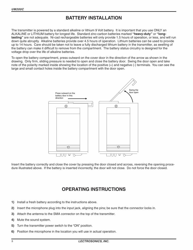
UM200C
BATTERY INSTALLATION
The transmitter is powered by a standard alkaline or lithium 9 Volt battery It is important that you use ONLY an ALKALINE or LITHIUM battery for longest life Standard zinc-carbon batteries marked ldquoheavy-dutyrdquo or ldquolongshylastingrdquo are not adequate Ni-cad rechargeable batteries will only provide 15 hours of operation or less and will run down quite abruptly Alkaline batteries provide over 45 hours of operation Lithium batteries can be used to provide up to 14 hours Care should be taken not to leave a fully discharged lithium battery in the transmitter as swelling of the battery can make it difficult to remove from the compartment The battery status circuitry is designed for the voltage drop over the life of alkaline batteries
To open the battery compartment press outward on the cover door in the direction of the arrow as shown in the drawing Only firm sliding pressure is needed to open and close the battery door Swing the door open and take note of the polarity marked inside showing the location of the positive (+) and negative (-) terminals You can see the large and small contact holes inside the battery compartment with the door open
Swing the door openPress outward on the
battery door in this direction
Insert the battery correctly and close the cover by pressing the door closed and across reversing the opening proceshydure illustrated above If the battery is inserted incorrectly the door will not close Do not force the door closed
OPERATING INSTRUCTIONS
1) Install a fresh battery according to the instructions above
2) Insert the microphone plug into the input jack aligning the pins be sure that the connector locks in
3) Attach the antenna to the SMA connector on the top of the transmitter
4) Mute the sound system
5) Turn the transmitter power switch to the ldquoONrdquo position
6) Position the microphone in the location you will use in actual operation
LECTROSONICS INC 8
Frequency Agile UHF Belt-Pack Transmitter
7) While speaking or singing at the same voice level that will actually be used observe the MODULATION LEDs Adjust the AUDIO LEVEL control knob until the LEDs begin to light Start at a low setting where neither LED lights as you speak Gradually turn the gain up until one LED lights then the other
The -20 LED lights when the audio level is about 12dB below full modulation The ldquo0rdquo LED lights when the limiter begins to operate There is over 30dB of limiting range without overload above the ldquo0rdquo LED so it is desirable that the it lights up occasionally during use
8) Once the gain has been adjusted the audio system audio can be turned on to make level adjustments Set the power switch to the ON position and adjust the receiver andor sound system level as required Please note there will be a delay between the moment the switch is thrown and the time when audio will actually appear at the receiver output This intentional delay eliminates turn on thumps and is controlled by the pilot tone squelch control
OPERATING NOTES
The AUDIO LEVEL control knob should not be used to control the volume of your sound system or recorder levels This gain adjustment matches the transmitter gain with the userrsquos voice level and microphone positioning
If the audio level is too high mdash both LEDs will light frequently or stay lit This condition may reduce the dynamic range of the audio signal
If the audio level is too low mdash neither LED will light or the -20 LED will light dimly This condition may cause hiss and noise in the audio or pumping and breating in the background noise
The first LED turns on 12dB below full deviation The ldquo0rdquo LED turns on at full deviation and indicates that the input shunt compressor is operating The input limiter will handle peaks over 30dB above full modulation regardless of the gain control setting The limiter uses a true absolute value circuit to detect both positive and negative peaks The attack time is 5 milliseconds and the release time is 200 milliseconds Occasional limiting is desirable indicating that the gain is correctly set and the transmitter is fully modulated for optimum signal to noise ratio
Different voices will usually require different settings of the AUDIO LEVEL control so check this adjustment as each new person uses the system If several different people will be using the transmitter and there is not time to make the adjustment for each individual adjust it for the loudest voice
ADJUSTING THE TRANSMITTER FREQUENCY If you are experiencing interference from another signal on your frequency you may want to change the operating frequency of your system The left switch changes the operating frequency by 16 MHz per step and the right switch changes it 100 kHz per step If you are experiencing interference change the operating frequency in 100 kHz steps to find a clear channel If it is not possible to find a clear channel using the 100 kHz switch return it to its original position and change the 16 MHz switch by one click then try the 100 kHz switch again
To gain access to these switches slide the access door sideways with a fingernail
Note With the UDR200A receiver these switches also appear on the front panel of the receiver Normally you should set the transmitter switches to match the receiver switch settings
0 1 2
3 4 5
6 789
A B C D
E F 0 1
2 3 4 5
6 789
A B C D
E F
With the UDR200B receiver the front panel LED character display will indicate the correct transmitter switch settings
Rio Rancho NM ndash USA 9
UM200C
MICROPHONE CORD TERMINATION
1
2 3
45
VIEW FROM SOLDER SIDE OF PINS
03
015 Heatshrink Tubing
TA5F Connector Assembly
Mic Cord Stripping Instructions
Caution Do not allow the shield wire to touch any metal part of the connector shell The shield wire is the antenna on VHF models and poor operating range will result
Shield Wire
Crimp Tabs
Rubber InsulationCrimp
TabsRubber Insulation
NoteThis termination is required on VHF transmitters and will still work fine on UHF transmitters
LECTROSONICS INC 10
Frequency Agile UHF Belt-Pack Transmitter
5-PIN INPUT JACK WIRING
The wiring diagrams shown on the next page represent the basic wiring necessary for the most common types of microphones and other audio inputs Some microphones may require extra jumpers or a slight variation on the diashygrams shown
Caution - When wiring the connector do not use the connector body for any electrical connections A common mistake is to use the connector body as an audio ground The connector body is
already used as an RF ground on VHF models and no other use is permitted
Itrsquos virtually impossible to keep completely up to date on changes that other manufacturers make to their products It is possible that you may encounter a microphone that differs from these instructions If this occurs please call our toll-free number listed on page 13 of this instruction manual Our service department can answer your questions regarding microphone compatibility
When used on a wireless transmitter the microphone element is in the proximity of the RF coming from the transmitter The nature of electret microphones makes them sensitive to RF which can cause problems with the microphone transmitter compatibility If the electret microphone is not designed properly for use with wireless transmitters it may be necessary to install a chip capacitor in the mic capsule or connector to block the RF from entering the electret capsule This modification is shown on the next page
FB
10k
1k5
100 4
3
2
1
+
POS BIAS (OR GND)
MIC
SOURCE LOAD
LINE IN
NEG GND (OR BIAS) +
1k
10uF330pF
330pF
330pF
330pF
4 3
21 5
LECTROSONICS 5V Mic Bias
To Mic Amp
Input Jack Input Circuit
VHF transmitters use the shield of the microphone cord as the antenna The UM200C uses a 14 wave flexible wire to radiate the RF signal There is really not much difference between these two approaches with respect to the effect of the RF on the microphone capsule Even in transmitters that utilize a ldquodangling wirerdquo the microphone is still part of the ldquoground planerdquo and is therefore still in the antenna circuit
PIN 1 Shield (ground) for positive biased electret lavalier microphones Bias voltage source for negative biased electret lavalier microphones Shield (ground) for dynamic microphones and line level inputs
PIN 2 Shield (ground) for negative biased electret lavalier microphones Bias voltage source for positive biased electret lavalier microphones
PIN 3 Low impedance microphone level input for dynamic microphones Also accepts hand-held electret microshyphones provided the microphone has its own built-in battery
PIN 4 1K Ohm source load for non-Lectrosonics electret microphones Use in conjunction with other pins to provide attenuation of high level input signals
PIN 5 High impedance line level input for tape decks mixer outputs musical instruments etc
Rio Rancho NM ndash USA 11
UM200C
RF BYPASSING 2 WIRE MIC 3 WIRE MIC
Some mics require RF protection to keep the radio signal from affecting the capsule even though the transmitter input circuitry is already RF bypassed (see schematic diagram)
If the mic is wired as directed and you are having difficulty with squealing high noise or poor frequency response RF is likely to be the cause
The best RF protection is accomplished by installing RF bypass capacitors at the mic capsule If this is not possible or if you are still having problems capacitors can be installed on the mic wires inside the TA5F connector housing
Install the capacitors as follows Use 330 pF capacitors Capacitors are available from Lectrosonics Please specify the part number for the desired lead style
Leaded capacitors PN 15117 Leadless capacitors PN SCC330P
All Lectrosonics lavalier mics are already bypassed and do not need any additional capacitors installed for proper operation
BODY GROUND Caution - When wiring the connector do not use the connector body for any electrical connections A common mistake is to use the connector body as an audio ground The connector body is already used as an RF ground on VHF models and no other use is permitted
LINE LEVEL SIGNALS The normal hookup for line level signals is Signal Hot to pin 5 Signal Gnd to pin 1 pin 4 jumped to pin 1 and pin 3 jumped to pin 1 This gives a 40dB attenuator that allows signal levels much higher than 3V to be applied without limiting
If more headroom is needed insert a 100k resistor in series with pin 5 Put this resistor inside the TA5F connector to minimize noise pickup
If lower than normal line levels (less than 1V) are expected use this hookup Signal Hot to pin 5 Signal Gnd to pin 1 and pin 4 jumpered to pin 1 This provides a 20dB attenuator allowing signals as high as 3V to be applied without limiting
WIRING HOOKUPS FOR DIFFERENT SOURCES
CAPSULE CAPSULE
SHIELD
AUDIO
SHIELD
AUDIO
BIAS TA5F
CONNECTOR TA5F
CONNECTOR
Preferred locations for bypass capacitors
Alternate locations for bypass capacitors
PIN
123
4 5
PIN SHIELD 11
AUDIO 22
2 WIRE ELECTRET MIC3 WIRE ELECTRET MIC 3
POSITIVE BIAS 3
NEGATIVE BIAS
1 23
4 5
44 TA5F 5
TA5F 5 PLUGPLUG
SHIELD
AUDIO
BIAS
SLEEVEPIN PINSHIELD SHIELD 1
TIP
1 2 2AUDIOAUDIO2 WIRE ELECTRET MIC 3 3POSITIVE BIAS 4
123
4 5
LINE LEVEL
1 23
4 5
4TA5F TA5FRCA or 14 PLUG 5 PLUG 5 PLUG(See notes on lsquoLINE LEVEL SIGNALSrdquo above)
3
12 PINPIN PIN
Dynamic LO Z mic or electret with manufacturers power supply
SHIELD 1 11 2 22
3 33
1 23
4 5
44
123
4 5
DYNAMIC TA5FTA5F MIC LEVEL 55 PLUGPLUG
SHIELD
BIAS
AUDIO 3 WIRE ELECTRET MIC
NEGATIVE BIAS
LECTROSONICS INC 12
Frequency Agile UHF Belt-Pack Transmitter
TROUBLESHOOTING
Before going through the following chart be sure that you have a good battery in the transmitter It is important that you follow these steps in the sequence listed
SYMPTOM POSSIBLE CAUSE
TRANSMITTER BATTERY LED OFF 1) Battery is inserted backwards 2) Battery is dead
NO TRANSMITTER MODULATION LEDs 1) Gain control turned all the way down 2) Battery is in backwards Check power LED 3) Mic capsule is damaged or malfunctioning 4) Mic cable damaged or mis-wired
RECEIVER RF LAMP OFF 1) Transmitter not turned on 2) Transmitter battery is dead 3) Receiver antenna missing or improperly positioned 4) Transmitter and receiver not on same frequency Check
switchesdisplay on transmitter and receiver 5) Operating range is too great 6) Transmitter antenna not connected
NO SOUND (OR LOW SOUND LEVEL) RECEIVER MOD LEVEL LEDs ARE ON 1) Receiver output level set too low
2) Receiver output is disconnected cable is defective or mis-wired
3) Sound system or recorder input is turned down
DISTORTED SOUND 1) Transmitter gain (audio level) is far too high Check mod level lamps on transmitter and receiver as it is being used (refer to pages 89 for details on gain adjustment)
2) Receiver output may be mis-matched with the sound system or recorder input Adjust output level on receiver to the correct level for the recorder mixer or sound system
3) Excessive wind noise or breath ldquopopsrdquo Re-position microphone andor use a larger windscreen
4) Transmitter is not set to same frequency as receiver Check that frequency select switches on receiver and transmitter match
HISS AND NOISE -- AUDIBLE DROPOUTS 1) Transmitter gain (audio level) far too low 2) Receiver antenna missing or obstructed 3) Transmitter antenna missing 4) Operating range too great
EXCESSIVE FEEDBACK 1) Transmitter gain (audio level) too high Check gain adjustment andor reduce receiver output level
2) Transmitter too close to speaker system 3) Mic is too far from userrsquos mouth
Rio Rancho NM ndash USA 13
UM200C
SPECIFICATIONS AND FEATURES
Operating frequencies 537600 to 607900 MHz 614100 to 767900 MHz
Frequency selection 256 frequencies in 100kHz steps
RF Power output 100 mW (nominal)
Pilot tone 32764 kHz (plusmn 2Hz) 5kHz deviation
Frequency stability plusmn 0002
Deviation plusmn 75 kHz (max)
Spurious radiation 90 dB below carrier
Equivalent input noise ndash126 dBV
Input level Nominal 2 mV to 300 mV before limiting Greater than 50V maximum with limiting
Input impedance Taps provided for 500 1k 10k Ohm
Input compressor Soft compressor gt30 dB range
Gain control range 43 dB semi-log rotary control
Modulation indicators Dual LEDs indicate modulation level 12dB below limiting and at the onset of limiting
Low frequency roll-off adjustment ndash18dBoctave 35Hz to 150Hz
Controls 2 position ldquoOFF-ONrdquo slide switch for noiseless turn onturn off operation Front panel knob adjusts audio gain Recessed control on side panel
adjusts low frequency rolloff Rotary switches on side panel adjust transmitter frequency
Audio Input Jack Switchcraft 5 pin locking (TA5F)
Antenna Detachable flexible wire supplied 50 Ohm port allows connection to test equipment
Battery Precision compartment auto-adjusts to accept any known alkaline 9 Volt battery (Wersquove tried 125 different ones)
Battery Life 45 hours (alkaline) 14 hours (lithium)
Weight 63 ozs including battery
Dimensions 31 x 24 x 75 inches
Emission Designator 180KF3E
Specifications subject to change without notice
LECTROSONICS INC 14
Frequency Agile UHF Belt-Pack Transmitter
SERVICE AND REPAIR
If your system malfunctions you should attempt to correct or isolate the trouble before concluding that the equipment needs repair Make sure you have followed the setup procedure and operating instructions Check out the interconshynecting cords and then go through the TROUBLESHOOTING section in the manual
We strongly recommend that you do not try to repair the equipment yourself and do not have the local repair shop attempt anything other than the simplest repair If the repair is more complicated than a broken wire or loose connecshytion send the unit to the factory for repair and service Donrsquot attempt to adjust any controls inside the units Once set at the factory the various controls and trimmers do not drift with age or vibration and never require readjustment There are no adjustments inside that will make a malfunctioning unit start working
LECTROSONICS service department is equipped and staffed to quickly repair your equipment In-warranty repairs are made at no charge in accordance with the terms of the warranty Out-of-warranty repairs are charged at a modest flat rate plus parts and shipping Since it takes almost as much time and effort to determine what is wrong as it does to make the repair there is a charge for an exact quotation We will be happy to quote approximate charges by phone for out-of-warranty repairs
RETURNING UNITS FOR REPAIR You will save yourself time and trouble if you will follow the steps below
A DO NOT return equipment to the factory for repair without first contacting us by letter or by phone We need to know the nature of the problem the model number and the serial number of the equipment We also need a phone number where you can be reached 8 am to 4 pm (Mountain Standard Time)
B After receiving your request we will issue you a return authorization number (RA) This number will help speed your repair through our receiving and repair departments The return authorization number must be clearly shown on the outside of the shipping container
C Pack the equipment carefully and ship to us shipping costs prepaid If necessary we can provide you with the proper packing materials UPS is usually the best way to ship the units Heavy units should be ldquodouble-boxedrdquo for safe transport
D We also strongly recommend that you insure the equipment since we cannot be responsible for loss of or damage to equipment that you ship Of course we insure the equipment when we ship it back to you
Mailing address Shipping address Lectrosonics Inc Lectrosonics Inc PO Box 15900 581 Laser Rd Rio Rancho NM 87174 Rio Rancho NM 87124 USA USA
Telephones Regular (505) 892-4501 Toll Free (800) 821-1121 FAX (505) 892-6243
World Wide Web httpwwwlectrosonicscom Email saleslectrosonicscom
Rio Rancho NM ndash USA 15
LIMITED ONE YEAR WARRANTY
The equipment is warranted for one year from date of purchase against defects in materials or workmanship provided it was purchased from an authorized dealer This warranty does not cover equipment which has been abused or damaged by careless handling or shipping This warranty does not apply to used or demonstrator equipment
Should any defect develop Lectrosonics Inc will at our option repair or replace any defective parts without charge for either parts or labor If Lectrosonics Inc cannot correct the defect in your equipment it will be replaced at no charge with a similar new item Lectrosonics Inc will pay for the cost of returning your equipment to you
This warranty applies only to items returned to Lectrosonics Inc or an authorized dealer shipping costs prepaid within one year from the date of purchase
This Limited Warranty is governed by the laws of the State of New Mexico It states the entire liablility of Lectrosonics Inc and the entire remedy of the purchaser for any breach of warranty as outlined above NEITHER LECTROSONICS INC NOR ANYONE INVOLVED IN THE PRODUCTION OR DELIVERY OF THE EQUIPMENT SHALL BE LIABLE FOR ANY INDIRECT SPECIAL PUNITIVE CONSEQUENTIAL OR INCIDENTAL DAMAGES ARISING OUT OF THE USE OR INABILITY TO USE THIS EQUIPMENT EVEN IF LECTROSONICS INC HAS BEEN ADVISED OF THE POSSIBILITY OF SUCH DAMAGES IN NO EVENT SHALL THE LIABILITY OF LECTROSONICS INC EXCEED THE PURCHASE PRICE OF ANY DEFECTIVE EQUIPMENT
This warranty gives you specific legal rights You may have additional legal rights which vary from state to state
LIMITED ONE YEAR WARRANTY
LECTROSONICS INC
581 LASER ROAD RIO RANCHO NM 87124 USA wwwlectrosonicscom
November 5 2003
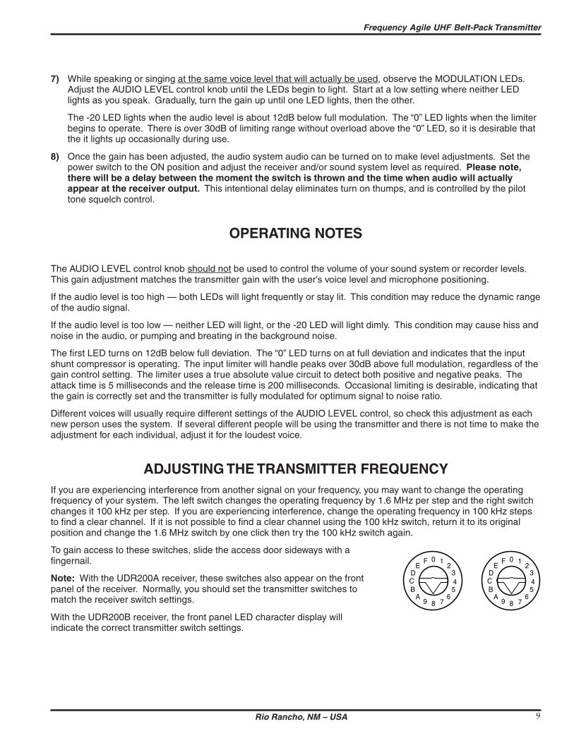
Frequency Agile UHF Belt-Pack Transmitter
7) While speaking or singing at the same voice level that will actually be used observe the MODULATION LEDs Adjust the AUDIO LEVEL control knob until the LEDs begin to light Start at a low setting where neither LED lights as you speak Gradually turn the gain up until one LED lights then the other
The -20 LED lights when the audio level is about 12dB below full modulation The ldquo0rdquo LED lights when the limiter begins to operate There is over 30dB of limiting range without overload above the ldquo0rdquo LED so it is desirable that the it lights up occasionally during use
8) Once the gain has been adjusted the audio system audio can be turned on to make level adjustments Set the power switch to the ON position and adjust the receiver andor sound system level as required Please note there will be a delay between the moment the switch is thrown and the time when audio will actually appear at the receiver output This intentional delay eliminates turn on thumps and is controlled by the pilot tone squelch control
OPERATING NOTES
The AUDIO LEVEL control knob should not be used to control the volume of your sound system or recorder levels This gain adjustment matches the transmitter gain with the userrsquos voice level and microphone positioning
If the audio level is too high mdash both LEDs will light frequently or stay lit This condition may reduce the dynamic range of the audio signal
If the audio level is too low mdash neither LED will light or the -20 LED will light dimly This condition may cause hiss and noise in the audio or pumping and breating in the background noise
The first LED turns on 12dB below full deviation The ldquo0rdquo LED turns on at full deviation and indicates that the input shunt compressor is operating The input limiter will handle peaks over 30dB above full modulation regardless of the gain control setting The limiter uses a true absolute value circuit to detect both positive and negative peaks The attack time is 5 milliseconds and the release time is 200 milliseconds Occasional limiting is desirable indicating that the gain is correctly set and the transmitter is fully modulated for optimum signal to noise ratio
Different voices will usually require different settings of the AUDIO LEVEL control so check this adjustment as each new person uses the system If several different people will be using the transmitter and there is not time to make the adjustment for each individual adjust it for the loudest voice
ADJUSTING THE TRANSMITTER FREQUENCY If you are experiencing interference from another signal on your frequency you may want to change the operating frequency of your system The left switch changes the operating frequency by 16 MHz per step and the right switch changes it 100 kHz per step If you are experiencing interference change the operating frequency in 100 kHz steps to find a clear channel If it is not possible to find a clear channel using the 100 kHz switch return it to its original position and change the 16 MHz switch by one click then try the 100 kHz switch again
To gain access to these switches slide the access door sideways with a fingernail
Note With the UDR200A receiver these switches also appear on the front panel of the receiver Normally you should set the transmitter switches to match the receiver switch settings
0 1 2
3 4 5
6 789
A B C D
E F 0 1
2 3 4 5
6 789
A B C D
E F
With the UDR200B receiver the front panel LED character display will indicate the correct transmitter switch settings
Rio Rancho NM ndash USA 9
UM200C
MICROPHONE CORD TERMINATION
1
2 3
45
VIEW FROM SOLDER SIDE OF PINS
03
015 Heatshrink Tubing
TA5F Connector Assembly
Mic Cord Stripping Instructions
Caution Do not allow the shield wire to touch any metal part of the connector shell The shield wire is the antenna on VHF models and poor operating range will result
Shield Wire
Crimp Tabs
Rubber InsulationCrimp
TabsRubber Insulation
NoteThis termination is required on VHF transmitters and will still work fine on UHF transmitters
LECTROSONICS INC 10
Frequency Agile UHF Belt-Pack Transmitter
5-PIN INPUT JACK WIRING
The wiring diagrams shown on the next page represent the basic wiring necessary for the most common types of microphones and other audio inputs Some microphones may require extra jumpers or a slight variation on the diashygrams shown
Caution - When wiring the connector do not use the connector body for any electrical connections A common mistake is to use the connector body as an audio ground The connector body is
already used as an RF ground on VHF models and no other use is permitted
Itrsquos virtually impossible to keep completely up to date on changes that other manufacturers make to their products It is possible that you may encounter a microphone that differs from these instructions If this occurs please call our toll-free number listed on page 13 of this instruction manual Our service department can answer your questions regarding microphone compatibility
When used on a wireless transmitter the microphone element is in the proximity of the RF coming from the transmitter The nature of electret microphones makes them sensitive to RF which can cause problems with the microphone transmitter compatibility If the electret microphone is not designed properly for use with wireless transmitters it may be necessary to install a chip capacitor in the mic capsule or connector to block the RF from entering the electret capsule This modification is shown on the next page
FB
10k
1k5
100 4
3
2
1
+
POS BIAS (OR GND)
MIC
SOURCE LOAD
LINE IN
NEG GND (OR BIAS) +
1k
10uF330pF
330pF
330pF
330pF
4 3
21 5
LECTROSONICS 5V Mic Bias
To Mic Amp
Input Jack Input Circuit
VHF transmitters use the shield of the microphone cord as the antenna The UM200C uses a 14 wave flexible wire to radiate the RF signal There is really not much difference between these two approaches with respect to the effect of the RF on the microphone capsule Even in transmitters that utilize a ldquodangling wirerdquo the microphone is still part of the ldquoground planerdquo and is therefore still in the antenna circuit
PIN 1 Shield (ground) for positive biased electret lavalier microphones Bias voltage source for negative biased electret lavalier microphones Shield (ground) for dynamic microphones and line level inputs
PIN 2 Shield (ground) for negative biased electret lavalier microphones Bias voltage source for positive biased electret lavalier microphones
PIN 3 Low impedance microphone level input for dynamic microphones Also accepts hand-held electret microshyphones provided the microphone has its own built-in battery
PIN 4 1K Ohm source load for non-Lectrosonics electret microphones Use in conjunction with other pins to provide attenuation of high level input signals
PIN 5 High impedance line level input for tape decks mixer outputs musical instruments etc
Rio Rancho NM ndash USA 11
UM200C
RF BYPASSING 2 WIRE MIC 3 WIRE MIC
Some mics require RF protection to keep the radio signal from affecting the capsule even though the transmitter input circuitry is already RF bypassed (see schematic diagram)
If the mic is wired as directed and you are having difficulty with squealing high noise or poor frequency response RF is likely to be the cause
The best RF protection is accomplished by installing RF bypass capacitors at the mic capsule If this is not possible or if you are still having problems capacitors can be installed on the mic wires inside the TA5F connector housing
Install the capacitors as follows Use 330 pF capacitors Capacitors are available from Lectrosonics Please specify the part number for the desired lead style
Leaded capacitors PN 15117 Leadless capacitors PN SCC330P
All Lectrosonics lavalier mics are already bypassed and do not need any additional capacitors installed for proper operation
BODY GROUND Caution - When wiring the connector do not use the connector body for any electrical connections A common mistake is to use the connector body as an audio ground The connector body is already used as an RF ground on VHF models and no other use is permitted
LINE LEVEL SIGNALS The normal hookup for line level signals is Signal Hot to pin 5 Signal Gnd to pin 1 pin 4 jumped to pin 1 and pin 3 jumped to pin 1 This gives a 40dB attenuator that allows signal levels much higher than 3V to be applied without limiting
If more headroom is needed insert a 100k resistor in series with pin 5 Put this resistor inside the TA5F connector to minimize noise pickup
If lower than normal line levels (less than 1V) are expected use this hookup Signal Hot to pin 5 Signal Gnd to pin 1 and pin 4 jumpered to pin 1 This provides a 20dB attenuator allowing signals as high as 3V to be applied without limiting
WIRING HOOKUPS FOR DIFFERENT SOURCES
CAPSULE CAPSULE
SHIELD
AUDIO
SHIELD
AUDIO
BIAS TA5F
CONNECTOR TA5F
CONNECTOR
Preferred locations for bypass capacitors
Alternate locations for bypass capacitors
PIN
123
4 5
PIN SHIELD 11
AUDIO 22
2 WIRE ELECTRET MIC3 WIRE ELECTRET MIC 3
POSITIVE BIAS 3
NEGATIVE BIAS
1 23
4 5
44 TA5F 5
TA5F 5 PLUGPLUG
SHIELD
AUDIO
BIAS
SLEEVEPIN PINSHIELD SHIELD 1
TIP
1 2 2AUDIOAUDIO2 WIRE ELECTRET MIC 3 3POSITIVE BIAS 4
123
4 5
LINE LEVEL
1 23
4 5
4TA5F TA5FRCA or 14 PLUG 5 PLUG 5 PLUG(See notes on lsquoLINE LEVEL SIGNALSrdquo above)
3
12 PINPIN PIN
Dynamic LO Z mic or electret with manufacturers power supply
SHIELD 1 11 2 22
3 33
1 23
4 5
44
123
4 5
DYNAMIC TA5FTA5F MIC LEVEL 55 PLUGPLUG
SHIELD
BIAS
AUDIO 3 WIRE ELECTRET MIC
NEGATIVE BIAS
LECTROSONICS INC 12
Frequency Agile UHF Belt-Pack Transmitter
TROUBLESHOOTING
Before going through the following chart be sure that you have a good battery in the transmitter It is important that you follow these steps in the sequence listed
SYMPTOM POSSIBLE CAUSE
TRANSMITTER BATTERY LED OFF 1) Battery is inserted backwards 2) Battery is dead
NO TRANSMITTER MODULATION LEDs 1) Gain control turned all the way down 2) Battery is in backwards Check power LED 3) Mic capsule is damaged or malfunctioning 4) Mic cable damaged or mis-wired
RECEIVER RF LAMP OFF 1) Transmitter not turned on 2) Transmitter battery is dead 3) Receiver antenna missing or improperly positioned 4) Transmitter and receiver not on same frequency Check
switchesdisplay on transmitter and receiver 5) Operating range is too great 6) Transmitter antenna not connected
NO SOUND (OR LOW SOUND LEVEL) RECEIVER MOD LEVEL LEDs ARE ON 1) Receiver output level set too low
2) Receiver output is disconnected cable is defective or mis-wired
3) Sound system or recorder input is turned down
DISTORTED SOUND 1) Transmitter gain (audio level) is far too high Check mod level lamps on transmitter and receiver as it is being used (refer to pages 89 for details on gain adjustment)
2) Receiver output may be mis-matched with the sound system or recorder input Adjust output level on receiver to the correct level for the recorder mixer or sound system
3) Excessive wind noise or breath ldquopopsrdquo Re-position microphone andor use a larger windscreen
4) Transmitter is not set to same frequency as receiver Check that frequency select switches on receiver and transmitter match
HISS AND NOISE -- AUDIBLE DROPOUTS 1) Transmitter gain (audio level) far too low 2) Receiver antenna missing or obstructed 3) Transmitter antenna missing 4) Operating range too great
EXCESSIVE FEEDBACK 1) Transmitter gain (audio level) too high Check gain adjustment andor reduce receiver output level
2) Transmitter too close to speaker system 3) Mic is too far from userrsquos mouth
Rio Rancho NM ndash USA 13
UM200C
SPECIFICATIONS AND FEATURES
Operating frequencies 537600 to 607900 MHz 614100 to 767900 MHz
Frequency selection 256 frequencies in 100kHz steps
RF Power output 100 mW (nominal)
Pilot tone 32764 kHz (plusmn 2Hz) 5kHz deviation
Frequency stability plusmn 0002
Deviation plusmn 75 kHz (max)
Spurious radiation 90 dB below carrier
Equivalent input noise ndash126 dBV
Input level Nominal 2 mV to 300 mV before limiting Greater than 50V maximum with limiting
Input impedance Taps provided for 500 1k 10k Ohm
Input compressor Soft compressor gt30 dB range
Gain control range 43 dB semi-log rotary control
Modulation indicators Dual LEDs indicate modulation level 12dB below limiting and at the onset of limiting
Low frequency roll-off adjustment ndash18dBoctave 35Hz to 150Hz
Controls 2 position ldquoOFF-ONrdquo slide switch for noiseless turn onturn off operation Front panel knob adjusts audio gain Recessed control on side panel
adjusts low frequency rolloff Rotary switches on side panel adjust transmitter frequency
Audio Input Jack Switchcraft 5 pin locking (TA5F)
Antenna Detachable flexible wire supplied 50 Ohm port allows connection to test equipment
Battery Precision compartment auto-adjusts to accept any known alkaline 9 Volt battery (Wersquove tried 125 different ones)
Battery Life 45 hours (alkaline) 14 hours (lithium)
Weight 63 ozs including battery
Dimensions 31 x 24 x 75 inches
Emission Designator 180KF3E
Specifications subject to change without notice
LECTROSONICS INC 14
Frequency Agile UHF Belt-Pack Transmitter
SERVICE AND REPAIR
If your system malfunctions you should attempt to correct or isolate the trouble before concluding that the equipment needs repair Make sure you have followed the setup procedure and operating instructions Check out the interconshynecting cords and then go through the TROUBLESHOOTING section in the manual
We strongly recommend that you do not try to repair the equipment yourself and do not have the local repair shop attempt anything other than the simplest repair If the repair is more complicated than a broken wire or loose connecshytion send the unit to the factory for repair and service Donrsquot attempt to adjust any controls inside the units Once set at the factory the various controls and trimmers do not drift with age or vibration and never require readjustment There are no adjustments inside that will make a malfunctioning unit start working
LECTROSONICS service department is equipped and staffed to quickly repair your equipment In-warranty repairs are made at no charge in accordance with the terms of the warranty Out-of-warranty repairs are charged at a modest flat rate plus parts and shipping Since it takes almost as much time and effort to determine what is wrong as it does to make the repair there is a charge for an exact quotation We will be happy to quote approximate charges by phone for out-of-warranty repairs
RETURNING UNITS FOR REPAIR You will save yourself time and trouble if you will follow the steps below
A DO NOT return equipment to the factory for repair without first contacting us by letter or by phone We need to know the nature of the problem the model number and the serial number of the equipment We also need a phone number where you can be reached 8 am to 4 pm (Mountain Standard Time)
B After receiving your request we will issue you a return authorization number (RA) This number will help speed your repair through our receiving and repair departments The return authorization number must be clearly shown on the outside of the shipping container
C Pack the equipment carefully and ship to us shipping costs prepaid If necessary we can provide you with the proper packing materials UPS is usually the best way to ship the units Heavy units should be ldquodouble-boxedrdquo for safe transport
D We also strongly recommend that you insure the equipment since we cannot be responsible for loss of or damage to equipment that you ship Of course we insure the equipment when we ship it back to you
Mailing address Shipping address Lectrosonics Inc Lectrosonics Inc PO Box 15900 581 Laser Rd Rio Rancho NM 87174 Rio Rancho NM 87124 USA USA
Telephones Regular (505) 892-4501 Toll Free (800) 821-1121 FAX (505) 892-6243
World Wide Web httpwwwlectrosonicscom Email saleslectrosonicscom
Rio Rancho NM ndash USA 15
LIMITED ONE YEAR WARRANTY
The equipment is warranted for one year from date of purchase against defects in materials or workmanship provided it was purchased from an authorized dealer This warranty does not cover equipment which has been abused or damaged by careless handling or shipping This warranty does not apply to used or demonstrator equipment
Should any defect develop Lectrosonics Inc will at our option repair or replace any defective parts without charge for either parts or labor If Lectrosonics Inc cannot correct the defect in your equipment it will be replaced at no charge with a similar new item Lectrosonics Inc will pay for the cost of returning your equipment to you
This warranty applies only to items returned to Lectrosonics Inc or an authorized dealer shipping costs prepaid within one year from the date of purchase
This Limited Warranty is governed by the laws of the State of New Mexico It states the entire liablility of Lectrosonics Inc and the entire remedy of the purchaser for any breach of warranty as outlined above NEITHER LECTROSONICS INC NOR ANYONE INVOLVED IN THE PRODUCTION OR DELIVERY OF THE EQUIPMENT SHALL BE LIABLE FOR ANY INDIRECT SPECIAL PUNITIVE CONSEQUENTIAL OR INCIDENTAL DAMAGES ARISING OUT OF THE USE OR INABILITY TO USE THIS EQUIPMENT EVEN IF LECTROSONICS INC HAS BEEN ADVISED OF THE POSSIBILITY OF SUCH DAMAGES IN NO EVENT SHALL THE LIABILITY OF LECTROSONICS INC EXCEED THE PURCHASE PRICE OF ANY DEFECTIVE EQUIPMENT
This warranty gives you specific legal rights You may have additional legal rights which vary from state to state
LIMITED ONE YEAR WARRANTY
LECTROSONICS INC
581 LASER ROAD RIO RANCHO NM 87124 USA wwwlectrosonicscom
November 5 2003
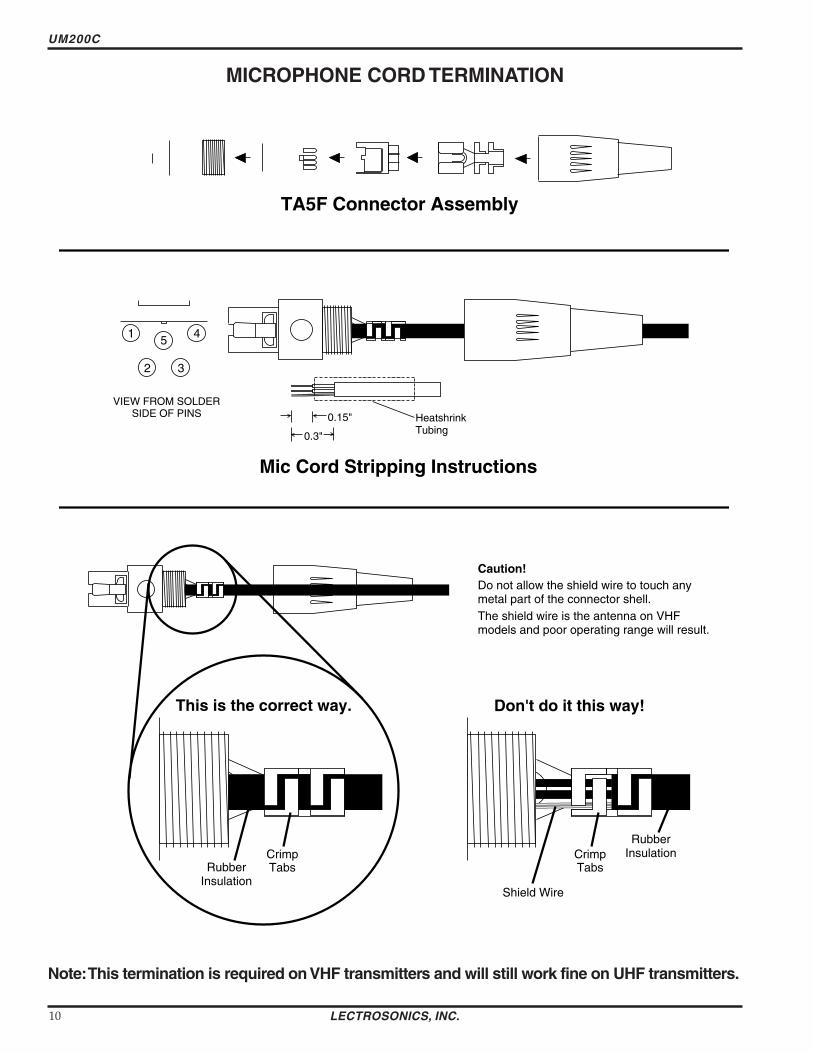
UM200C
MICROPHONE CORD TERMINATION
1
2 3
45
VIEW FROM SOLDER SIDE OF PINS
03
015 Heatshrink Tubing
TA5F Connector Assembly
Mic Cord Stripping Instructions
Caution Do not allow the shield wire to touch any metal part of the connector shell The shield wire is the antenna on VHF models and poor operating range will result
Shield Wire
Crimp Tabs
Rubber InsulationCrimp
TabsRubber Insulation
NoteThis termination is required on VHF transmitters and will still work fine on UHF transmitters
LECTROSONICS INC 10
Frequency Agile UHF Belt-Pack Transmitter
5-PIN INPUT JACK WIRING
The wiring diagrams shown on the next page represent the basic wiring necessary for the most common types of microphones and other audio inputs Some microphones may require extra jumpers or a slight variation on the diashygrams shown
Caution - When wiring the connector do not use the connector body for any electrical connections A common mistake is to use the connector body as an audio ground The connector body is
already used as an RF ground on VHF models and no other use is permitted
Itrsquos virtually impossible to keep completely up to date on changes that other manufacturers make to their products It is possible that you may encounter a microphone that differs from these instructions If this occurs please call our toll-free number listed on page 13 of this instruction manual Our service department can answer your questions regarding microphone compatibility
When used on a wireless transmitter the microphone element is in the proximity of the RF coming from the transmitter The nature of electret microphones makes them sensitive to RF which can cause problems with the microphone transmitter compatibility If the electret microphone is not designed properly for use with wireless transmitters it may be necessary to install a chip capacitor in the mic capsule or connector to block the RF from entering the electret capsule This modification is shown on the next page
FB
10k
1k5
100 4
3
2
1
+
POS BIAS (OR GND)
MIC
SOURCE LOAD
LINE IN
NEG GND (OR BIAS) +
1k
10uF330pF
330pF
330pF
330pF
4 3
21 5
LECTROSONICS 5V Mic Bias
To Mic Amp
Input Jack Input Circuit
VHF transmitters use the shield of the microphone cord as the antenna The UM200C uses a 14 wave flexible wire to radiate the RF signal There is really not much difference between these two approaches with respect to the effect of the RF on the microphone capsule Even in transmitters that utilize a ldquodangling wirerdquo the microphone is still part of the ldquoground planerdquo and is therefore still in the antenna circuit
PIN 1 Shield (ground) for positive biased electret lavalier microphones Bias voltage source for negative biased electret lavalier microphones Shield (ground) for dynamic microphones and line level inputs
PIN 2 Shield (ground) for negative biased electret lavalier microphones Bias voltage source for positive biased electret lavalier microphones
PIN 3 Low impedance microphone level input for dynamic microphones Also accepts hand-held electret microshyphones provided the microphone has its own built-in battery
PIN 4 1K Ohm source load for non-Lectrosonics electret microphones Use in conjunction with other pins to provide attenuation of high level input signals
PIN 5 High impedance line level input for tape decks mixer outputs musical instruments etc
Rio Rancho NM ndash USA 11
UM200C
RF BYPASSING 2 WIRE MIC 3 WIRE MIC
Some mics require RF protection to keep the radio signal from affecting the capsule even though the transmitter input circuitry is already RF bypassed (see schematic diagram)
If the mic is wired as directed and you are having difficulty with squealing high noise or poor frequency response RF is likely to be the cause
The best RF protection is accomplished by installing RF bypass capacitors at the mic capsule If this is not possible or if you are still having problems capacitors can be installed on the mic wires inside the TA5F connector housing
Install the capacitors as follows Use 330 pF capacitors Capacitors are available from Lectrosonics Please specify the part number for the desired lead style
Leaded capacitors PN 15117 Leadless capacitors PN SCC330P
All Lectrosonics lavalier mics are already bypassed and do not need any additional capacitors installed for proper operation
BODY GROUND Caution - When wiring the connector do not use the connector body for any electrical connections A common mistake is to use the connector body as an audio ground The connector body is already used as an RF ground on VHF models and no other use is permitted
LINE LEVEL SIGNALS The normal hookup for line level signals is Signal Hot to pin 5 Signal Gnd to pin 1 pin 4 jumped to pin 1 and pin 3 jumped to pin 1 This gives a 40dB attenuator that allows signal levels much higher than 3V to be applied without limiting
If more headroom is needed insert a 100k resistor in series with pin 5 Put this resistor inside the TA5F connector to minimize noise pickup
If lower than normal line levels (less than 1V) are expected use this hookup Signal Hot to pin 5 Signal Gnd to pin 1 and pin 4 jumpered to pin 1 This provides a 20dB attenuator allowing signals as high as 3V to be applied without limiting
WIRING HOOKUPS FOR DIFFERENT SOURCES
CAPSULE CAPSULE
SHIELD
AUDIO
SHIELD
AUDIO
BIAS TA5F
CONNECTOR TA5F
CONNECTOR
Preferred locations for bypass capacitors
Alternate locations for bypass capacitors
PIN
123
4 5
PIN SHIELD 11
AUDIO 22
2 WIRE ELECTRET MIC3 WIRE ELECTRET MIC 3
POSITIVE BIAS 3
NEGATIVE BIAS
1 23
4 5
44 TA5F 5
TA5F 5 PLUGPLUG
SHIELD
AUDIO
BIAS
SLEEVEPIN PINSHIELD SHIELD 1
TIP
1 2 2AUDIOAUDIO2 WIRE ELECTRET MIC 3 3POSITIVE BIAS 4
123
4 5
LINE LEVEL
1 23
4 5
4TA5F TA5FRCA or 14 PLUG 5 PLUG 5 PLUG(See notes on lsquoLINE LEVEL SIGNALSrdquo above)
3
12 PINPIN PIN
Dynamic LO Z mic or electret with manufacturers power supply
SHIELD 1 11 2 22
3 33
1 23
4 5
44
123
4 5
DYNAMIC TA5FTA5F MIC LEVEL 55 PLUGPLUG
SHIELD
BIAS
AUDIO 3 WIRE ELECTRET MIC
NEGATIVE BIAS
LECTROSONICS INC 12
Frequency Agile UHF Belt-Pack Transmitter
TROUBLESHOOTING
Before going through the following chart be sure that you have a good battery in the transmitter It is important that you follow these steps in the sequence listed
SYMPTOM POSSIBLE CAUSE
TRANSMITTER BATTERY LED OFF 1) Battery is inserted backwards 2) Battery is dead
NO TRANSMITTER MODULATION LEDs 1) Gain control turned all the way down 2) Battery is in backwards Check power LED 3) Mic capsule is damaged or malfunctioning 4) Mic cable damaged or mis-wired
RECEIVER RF LAMP OFF 1) Transmitter not turned on 2) Transmitter battery is dead 3) Receiver antenna missing or improperly positioned 4) Transmitter and receiver not on same frequency Check
switchesdisplay on transmitter and receiver 5) Operating range is too great 6) Transmitter antenna not connected
NO SOUND (OR LOW SOUND LEVEL) RECEIVER MOD LEVEL LEDs ARE ON 1) Receiver output level set too low
2) Receiver output is disconnected cable is defective or mis-wired
3) Sound system or recorder input is turned down
DISTORTED SOUND 1) Transmitter gain (audio level) is far too high Check mod level lamps on transmitter and receiver as it is being used (refer to pages 89 for details on gain adjustment)
2) Receiver output may be mis-matched with the sound system or recorder input Adjust output level on receiver to the correct level for the recorder mixer or sound system
3) Excessive wind noise or breath ldquopopsrdquo Re-position microphone andor use a larger windscreen
4) Transmitter is not set to same frequency as receiver Check that frequency select switches on receiver and transmitter match
HISS AND NOISE -- AUDIBLE DROPOUTS 1) Transmitter gain (audio level) far too low 2) Receiver antenna missing or obstructed 3) Transmitter antenna missing 4) Operating range too great
EXCESSIVE FEEDBACK 1) Transmitter gain (audio level) too high Check gain adjustment andor reduce receiver output level
2) Transmitter too close to speaker system 3) Mic is too far from userrsquos mouth
Rio Rancho NM ndash USA 13
UM200C
SPECIFICATIONS AND FEATURES
Operating frequencies 537600 to 607900 MHz 614100 to 767900 MHz
Frequency selection 256 frequencies in 100kHz steps
RF Power output 100 mW (nominal)
Pilot tone 32764 kHz (plusmn 2Hz) 5kHz deviation
Frequency stability plusmn 0002
Deviation plusmn 75 kHz (max)
Spurious radiation 90 dB below carrier
Equivalent input noise ndash126 dBV
Input level Nominal 2 mV to 300 mV before limiting Greater than 50V maximum with limiting
Input impedance Taps provided for 500 1k 10k Ohm
Input compressor Soft compressor gt30 dB range
Gain control range 43 dB semi-log rotary control
Modulation indicators Dual LEDs indicate modulation level 12dB below limiting and at the onset of limiting
Low frequency roll-off adjustment ndash18dBoctave 35Hz to 150Hz
Controls 2 position ldquoOFF-ONrdquo slide switch for noiseless turn onturn off operation Front panel knob adjusts audio gain Recessed control on side panel
adjusts low frequency rolloff Rotary switches on side panel adjust transmitter frequency
Audio Input Jack Switchcraft 5 pin locking (TA5F)
Antenna Detachable flexible wire supplied 50 Ohm port allows connection to test equipment
Battery Precision compartment auto-adjusts to accept any known alkaline 9 Volt battery (Wersquove tried 125 different ones)
Battery Life 45 hours (alkaline) 14 hours (lithium)
Weight 63 ozs including battery
Dimensions 31 x 24 x 75 inches
Emission Designator 180KF3E
Specifications subject to change without notice
LECTROSONICS INC 14
Frequency Agile UHF Belt-Pack Transmitter
SERVICE AND REPAIR
If your system malfunctions you should attempt to correct or isolate the trouble before concluding that the equipment needs repair Make sure you have followed the setup procedure and operating instructions Check out the interconshynecting cords and then go through the TROUBLESHOOTING section in the manual
We strongly recommend that you do not try to repair the equipment yourself and do not have the local repair shop attempt anything other than the simplest repair If the repair is more complicated than a broken wire or loose connecshytion send the unit to the factory for repair and service Donrsquot attempt to adjust any controls inside the units Once set at the factory the various controls and trimmers do not drift with age or vibration and never require readjustment There are no adjustments inside that will make a malfunctioning unit start working
LECTROSONICS service department is equipped and staffed to quickly repair your equipment In-warranty repairs are made at no charge in accordance with the terms of the warranty Out-of-warranty repairs are charged at a modest flat rate plus parts and shipping Since it takes almost as much time and effort to determine what is wrong as it does to make the repair there is a charge for an exact quotation We will be happy to quote approximate charges by phone for out-of-warranty repairs
RETURNING UNITS FOR REPAIR You will save yourself time and trouble if you will follow the steps below
A DO NOT return equipment to the factory for repair without first contacting us by letter or by phone We need to know the nature of the problem the model number and the serial number of the equipment We also need a phone number where you can be reached 8 am to 4 pm (Mountain Standard Time)
B After receiving your request we will issue you a return authorization number (RA) This number will help speed your repair through our receiving and repair departments The return authorization number must be clearly shown on the outside of the shipping container
C Pack the equipment carefully and ship to us shipping costs prepaid If necessary we can provide you with the proper packing materials UPS is usually the best way to ship the units Heavy units should be ldquodouble-boxedrdquo for safe transport
D We also strongly recommend that you insure the equipment since we cannot be responsible for loss of or damage to equipment that you ship Of course we insure the equipment when we ship it back to you
Mailing address Shipping address Lectrosonics Inc Lectrosonics Inc PO Box 15900 581 Laser Rd Rio Rancho NM 87174 Rio Rancho NM 87124 USA USA
Telephones Regular (505) 892-4501 Toll Free (800) 821-1121 FAX (505) 892-6243
World Wide Web httpwwwlectrosonicscom Email saleslectrosonicscom
Rio Rancho NM ndash USA 15
LIMITED ONE YEAR WARRANTY
The equipment is warranted for one year from date of purchase against defects in materials or workmanship provided it was purchased from an authorized dealer This warranty does not cover equipment which has been abused or damaged by careless handling or shipping This warranty does not apply to used or demonstrator equipment
Should any defect develop Lectrosonics Inc will at our option repair or replace any defective parts without charge for either parts or labor If Lectrosonics Inc cannot correct the defect in your equipment it will be replaced at no charge with a similar new item Lectrosonics Inc will pay for the cost of returning your equipment to you
This warranty applies only to items returned to Lectrosonics Inc or an authorized dealer shipping costs prepaid within one year from the date of purchase
This Limited Warranty is governed by the laws of the State of New Mexico It states the entire liablility of Lectrosonics Inc and the entire remedy of the purchaser for any breach of warranty as outlined above NEITHER LECTROSONICS INC NOR ANYONE INVOLVED IN THE PRODUCTION OR DELIVERY OF THE EQUIPMENT SHALL BE LIABLE FOR ANY INDIRECT SPECIAL PUNITIVE CONSEQUENTIAL OR INCIDENTAL DAMAGES ARISING OUT OF THE USE OR INABILITY TO USE THIS EQUIPMENT EVEN IF LECTROSONICS INC HAS BEEN ADVISED OF THE POSSIBILITY OF SUCH DAMAGES IN NO EVENT SHALL THE LIABILITY OF LECTROSONICS INC EXCEED THE PURCHASE PRICE OF ANY DEFECTIVE EQUIPMENT
This warranty gives you specific legal rights You may have additional legal rights which vary from state to state
LIMITED ONE YEAR WARRANTY
LECTROSONICS INC
581 LASER ROAD RIO RANCHO NM 87124 USA wwwlectrosonicscom
November 5 2003
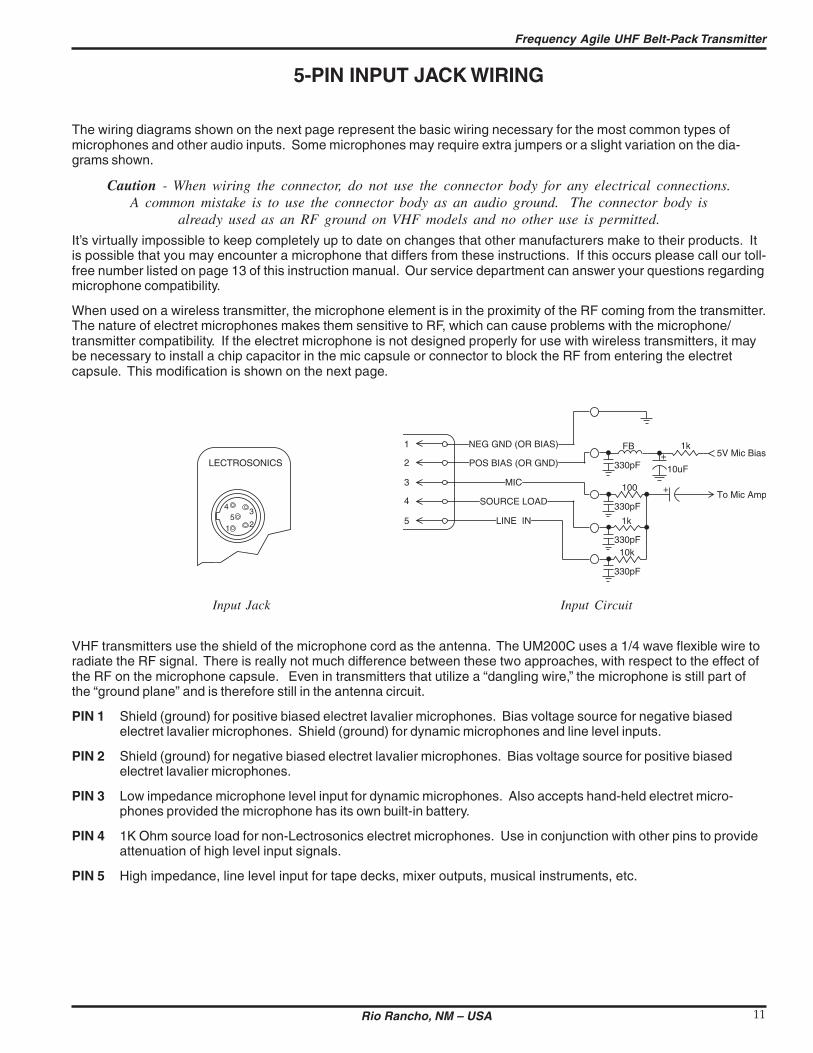
Frequency Agile UHF Belt-Pack Transmitter
5-PIN INPUT JACK WIRING
The wiring diagrams shown on the next page represent the basic wiring necessary for the most common types of microphones and other audio inputs Some microphones may require extra jumpers or a slight variation on the diashygrams shown
Caution - When wiring the connector do not use the connector body for any electrical connections A common mistake is to use the connector body as an audio ground The connector body is
already used as an RF ground on VHF models and no other use is permitted
Itrsquos virtually impossible to keep completely up to date on changes that other manufacturers make to their products It is possible that you may encounter a microphone that differs from these instructions If this occurs please call our toll-free number listed on page 13 of this instruction manual Our service department can answer your questions regarding microphone compatibility
When used on a wireless transmitter the microphone element is in the proximity of the RF coming from the transmitter The nature of electret microphones makes them sensitive to RF which can cause problems with the microphone transmitter compatibility If the electret microphone is not designed properly for use with wireless transmitters it may be necessary to install a chip capacitor in the mic capsule or connector to block the RF from entering the electret capsule This modification is shown on the next page
FB
10k
1k5
100 4
3
2
1
+
POS BIAS (OR GND)
MIC
SOURCE LOAD
LINE IN
NEG GND (OR BIAS) +
1k
10uF330pF
330pF
330pF
330pF
4 3
21 5
LECTROSONICS 5V Mic Bias
To Mic Amp
Input Jack Input Circuit
VHF transmitters use the shield of the microphone cord as the antenna The UM200C uses a 14 wave flexible wire to radiate the RF signal There is really not much difference between these two approaches with respect to the effect of the RF on the microphone capsule Even in transmitters that utilize a ldquodangling wirerdquo the microphone is still part of the ldquoground planerdquo and is therefore still in the antenna circuit
PIN 1 Shield (ground) for positive biased electret lavalier microphones Bias voltage source for negative biased electret lavalier microphones Shield (ground) for dynamic microphones and line level inputs
PIN 2 Shield (ground) for negative biased electret lavalier microphones Bias voltage source for positive biased electret lavalier microphones
PIN 3 Low impedance microphone level input for dynamic microphones Also accepts hand-held electret microshyphones provided the microphone has its own built-in battery
PIN 4 1K Ohm source load for non-Lectrosonics electret microphones Use in conjunction with other pins to provide attenuation of high level input signals
PIN 5 High impedance line level input for tape decks mixer outputs musical instruments etc
Rio Rancho NM ndash USA 11
UM200C
RF BYPASSING 2 WIRE MIC 3 WIRE MIC
Some mics require RF protection to keep the radio signal from affecting the capsule even though the transmitter input circuitry is already RF bypassed (see schematic diagram)
If the mic is wired as directed and you are having difficulty with squealing high noise or poor frequency response RF is likely to be the cause
The best RF protection is accomplished by installing RF bypass capacitors at the mic capsule If this is not possible or if you are still having problems capacitors can be installed on the mic wires inside the TA5F connector housing
Install the capacitors as follows Use 330 pF capacitors Capacitors are available from Lectrosonics Please specify the part number for the desired lead style
Leaded capacitors PN 15117 Leadless capacitors PN SCC330P
All Lectrosonics lavalier mics are already bypassed and do not need any additional capacitors installed for proper operation
BODY GROUND Caution - When wiring the connector do not use the connector body for any electrical connections A common mistake is to use the connector body as an audio ground The connector body is already used as an RF ground on VHF models and no other use is permitted
LINE LEVEL SIGNALS The normal hookup for line level signals is Signal Hot to pin 5 Signal Gnd to pin 1 pin 4 jumped to pin 1 and pin 3 jumped to pin 1 This gives a 40dB attenuator that allows signal levels much higher than 3V to be applied without limiting
If more headroom is needed insert a 100k resistor in series with pin 5 Put this resistor inside the TA5F connector to minimize noise pickup
If lower than normal line levels (less than 1V) are expected use this hookup Signal Hot to pin 5 Signal Gnd to pin 1 and pin 4 jumpered to pin 1 This provides a 20dB attenuator allowing signals as high as 3V to be applied without limiting
WIRING HOOKUPS FOR DIFFERENT SOURCES
CAPSULE CAPSULE
SHIELD
AUDIO
SHIELD
AUDIO
BIAS TA5F
CONNECTOR TA5F
CONNECTOR
Preferred locations for bypass capacitors
Alternate locations for bypass capacitors
PIN
123
4 5
PIN SHIELD 11
AUDIO 22
2 WIRE ELECTRET MIC3 WIRE ELECTRET MIC 3
POSITIVE BIAS 3
NEGATIVE BIAS
1 23
4 5
44 TA5F 5
TA5F 5 PLUGPLUG
SHIELD
AUDIO
BIAS
SLEEVEPIN PINSHIELD SHIELD 1
TIP
1 2 2AUDIOAUDIO2 WIRE ELECTRET MIC 3 3POSITIVE BIAS 4
123
4 5
LINE LEVEL
1 23
4 5
4TA5F TA5FRCA or 14 PLUG 5 PLUG 5 PLUG(See notes on lsquoLINE LEVEL SIGNALSrdquo above)
3
12 PINPIN PIN
Dynamic LO Z mic or electret with manufacturers power supply
SHIELD 1 11 2 22
3 33
1 23
4 5
44
123
4 5
DYNAMIC TA5FTA5F MIC LEVEL 55 PLUGPLUG
SHIELD
BIAS
AUDIO 3 WIRE ELECTRET MIC
NEGATIVE BIAS
LECTROSONICS INC 12
Frequency Agile UHF Belt-Pack Transmitter
TROUBLESHOOTING
Before going through the following chart be sure that you have a good battery in the transmitter It is important that you follow these steps in the sequence listed
SYMPTOM POSSIBLE CAUSE
TRANSMITTER BATTERY LED OFF 1) Battery is inserted backwards 2) Battery is dead
NO TRANSMITTER MODULATION LEDs 1) Gain control turned all the way down 2) Battery is in backwards Check power LED 3) Mic capsule is damaged or malfunctioning 4) Mic cable damaged or mis-wired
RECEIVER RF LAMP OFF 1) Transmitter not turned on 2) Transmitter battery is dead 3) Receiver antenna missing or improperly positioned 4) Transmitter and receiver not on same frequency Check
switchesdisplay on transmitter and receiver 5) Operating range is too great 6) Transmitter antenna not connected
NO SOUND (OR LOW SOUND LEVEL) RECEIVER MOD LEVEL LEDs ARE ON 1) Receiver output level set too low
2) Receiver output is disconnected cable is defective or mis-wired
3) Sound system or recorder input is turned down
DISTORTED SOUND 1) Transmitter gain (audio level) is far too high Check mod level lamps on transmitter and receiver as it is being used (refer to pages 89 for details on gain adjustment)
2) Receiver output may be mis-matched with the sound system or recorder input Adjust output level on receiver to the correct level for the recorder mixer or sound system
3) Excessive wind noise or breath ldquopopsrdquo Re-position microphone andor use a larger windscreen
4) Transmitter is not set to same frequency as receiver Check that frequency select switches on receiver and transmitter match
HISS AND NOISE -- AUDIBLE DROPOUTS 1) Transmitter gain (audio level) far too low 2) Receiver antenna missing or obstructed 3) Transmitter antenna missing 4) Operating range too great
EXCESSIVE FEEDBACK 1) Transmitter gain (audio level) too high Check gain adjustment andor reduce receiver output level
2) Transmitter too close to speaker system 3) Mic is too far from userrsquos mouth
Rio Rancho NM ndash USA 13
UM200C
SPECIFICATIONS AND FEATURES
Operating frequencies 537600 to 607900 MHz 614100 to 767900 MHz
Frequency selection 256 frequencies in 100kHz steps
RF Power output 100 mW (nominal)
Pilot tone 32764 kHz (plusmn 2Hz) 5kHz deviation
Frequency stability plusmn 0002
Deviation plusmn 75 kHz (max)
Spurious radiation 90 dB below carrier
Equivalent input noise ndash126 dBV
Input level Nominal 2 mV to 300 mV before limiting Greater than 50V maximum with limiting
Input impedance Taps provided for 500 1k 10k Ohm
Input compressor Soft compressor gt30 dB range
Gain control range 43 dB semi-log rotary control
Modulation indicators Dual LEDs indicate modulation level 12dB below limiting and at the onset of limiting
Low frequency roll-off adjustment ndash18dBoctave 35Hz to 150Hz
Controls 2 position ldquoOFF-ONrdquo slide switch for noiseless turn onturn off operation Front panel knob adjusts audio gain Recessed control on side panel
adjusts low frequency rolloff Rotary switches on side panel adjust transmitter frequency
Audio Input Jack Switchcraft 5 pin locking (TA5F)
Antenna Detachable flexible wire supplied 50 Ohm port allows connection to test equipment
Battery Precision compartment auto-adjusts to accept any known alkaline 9 Volt battery (Wersquove tried 125 different ones)
Battery Life 45 hours (alkaline) 14 hours (lithium)
Weight 63 ozs including battery
Dimensions 31 x 24 x 75 inches
Emission Designator 180KF3E
Specifications subject to change without notice
LECTROSONICS INC 14
Frequency Agile UHF Belt-Pack Transmitter
SERVICE AND REPAIR
If your system malfunctions you should attempt to correct or isolate the trouble before concluding that the equipment needs repair Make sure you have followed the setup procedure and operating instructions Check out the interconshynecting cords and then go through the TROUBLESHOOTING section in the manual
We strongly recommend that you do not try to repair the equipment yourself and do not have the local repair shop attempt anything other than the simplest repair If the repair is more complicated than a broken wire or loose connecshytion send the unit to the factory for repair and service Donrsquot attempt to adjust any controls inside the units Once set at the factory the various controls and trimmers do not drift with age or vibration and never require readjustment There are no adjustments inside that will make a malfunctioning unit start working
LECTROSONICS service department is equipped and staffed to quickly repair your equipment In-warranty repairs are made at no charge in accordance with the terms of the warranty Out-of-warranty repairs are charged at a modest flat rate plus parts and shipping Since it takes almost as much time and effort to determine what is wrong as it does to make the repair there is a charge for an exact quotation We will be happy to quote approximate charges by phone for out-of-warranty repairs
RETURNING UNITS FOR REPAIR You will save yourself time and trouble if you will follow the steps below
A DO NOT return equipment to the factory for repair without first contacting us by letter or by phone We need to know the nature of the problem the model number and the serial number of the equipment We also need a phone number where you can be reached 8 am to 4 pm (Mountain Standard Time)
B After receiving your request we will issue you a return authorization number (RA) This number will help speed your repair through our receiving and repair departments The return authorization number must be clearly shown on the outside of the shipping container
C Pack the equipment carefully and ship to us shipping costs prepaid If necessary we can provide you with the proper packing materials UPS is usually the best way to ship the units Heavy units should be ldquodouble-boxedrdquo for safe transport
D We also strongly recommend that you insure the equipment since we cannot be responsible for loss of or damage to equipment that you ship Of course we insure the equipment when we ship it back to you
Mailing address Shipping address Lectrosonics Inc Lectrosonics Inc PO Box 15900 581 Laser Rd Rio Rancho NM 87174 Rio Rancho NM 87124 USA USA
Telephones Regular (505) 892-4501 Toll Free (800) 821-1121 FAX (505) 892-6243
World Wide Web httpwwwlectrosonicscom Email saleslectrosonicscom
Rio Rancho NM ndash USA 15
LIMITED ONE YEAR WARRANTY
The equipment is warranted for one year from date of purchase against defects in materials or workmanship provided it was purchased from an authorized dealer This warranty does not cover equipment which has been abused or damaged by careless handling or shipping This warranty does not apply to used or demonstrator equipment
Should any defect develop Lectrosonics Inc will at our option repair or replace any defective parts without charge for either parts or labor If Lectrosonics Inc cannot correct the defect in your equipment it will be replaced at no charge with a similar new item Lectrosonics Inc will pay for the cost of returning your equipment to you
This warranty applies only to items returned to Lectrosonics Inc or an authorized dealer shipping costs prepaid within one year from the date of purchase
This Limited Warranty is governed by the laws of the State of New Mexico It states the entire liablility of Lectrosonics Inc and the entire remedy of the purchaser for any breach of warranty as outlined above NEITHER LECTROSONICS INC NOR ANYONE INVOLVED IN THE PRODUCTION OR DELIVERY OF THE EQUIPMENT SHALL BE LIABLE FOR ANY INDIRECT SPECIAL PUNITIVE CONSEQUENTIAL OR INCIDENTAL DAMAGES ARISING OUT OF THE USE OR INABILITY TO USE THIS EQUIPMENT EVEN IF LECTROSONICS INC HAS BEEN ADVISED OF THE POSSIBILITY OF SUCH DAMAGES IN NO EVENT SHALL THE LIABILITY OF LECTROSONICS INC EXCEED THE PURCHASE PRICE OF ANY DEFECTIVE EQUIPMENT
This warranty gives you specific legal rights You may have additional legal rights which vary from state to state
LIMITED ONE YEAR WARRANTY
LECTROSONICS INC
581 LASER ROAD RIO RANCHO NM 87124 USA wwwlectrosonicscom
November 5 2003
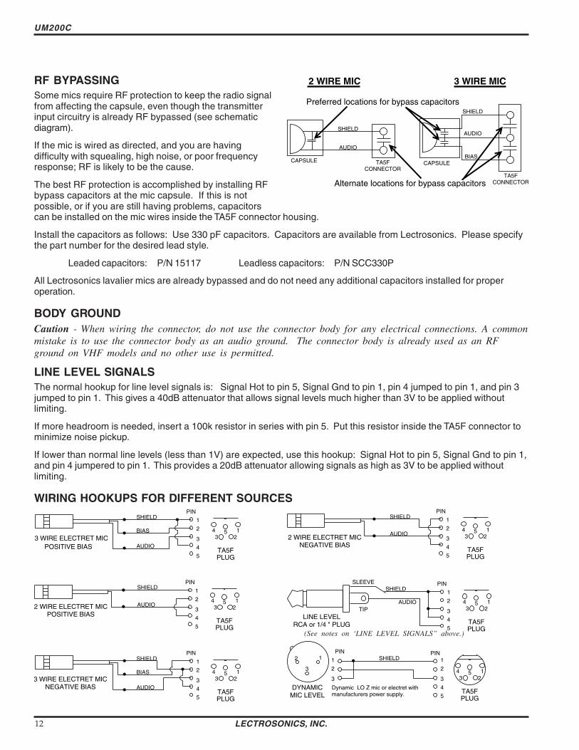
UM200C
RF BYPASSING 2 WIRE MIC 3 WIRE MIC
Some mics require RF protection to keep the radio signal from affecting the capsule even though the transmitter input circuitry is already RF bypassed (see schematic diagram)
If the mic is wired as directed and you are having difficulty with squealing high noise or poor frequency response RF is likely to be the cause
The best RF protection is accomplished by installing RF bypass capacitors at the mic capsule If this is not possible or if you are still having problems capacitors can be installed on the mic wires inside the TA5F connector housing
Install the capacitors as follows Use 330 pF capacitors Capacitors are available from Lectrosonics Please specify the part number for the desired lead style
Leaded capacitors PN 15117 Leadless capacitors PN SCC330P
All Lectrosonics lavalier mics are already bypassed and do not need any additional capacitors installed for proper operation
BODY GROUND Caution - When wiring the connector do not use the connector body for any electrical connections A common mistake is to use the connector body as an audio ground The connector body is already used as an RF ground on VHF models and no other use is permitted
LINE LEVEL SIGNALS The normal hookup for line level signals is Signal Hot to pin 5 Signal Gnd to pin 1 pin 4 jumped to pin 1 and pin 3 jumped to pin 1 This gives a 40dB attenuator that allows signal levels much higher than 3V to be applied without limiting
If more headroom is needed insert a 100k resistor in series with pin 5 Put this resistor inside the TA5F connector to minimize noise pickup
If lower than normal line levels (less than 1V) are expected use this hookup Signal Hot to pin 5 Signal Gnd to pin 1 and pin 4 jumpered to pin 1 This provides a 20dB attenuator allowing signals as high as 3V to be applied without limiting
WIRING HOOKUPS FOR DIFFERENT SOURCES
CAPSULE CAPSULE
SHIELD
AUDIO
SHIELD
AUDIO
BIAS TA5F
CONNECTOR TA5F
CONNECTOR
Preferred locations for bypass capacitors
Alternate locations for bypass capacitors
PIN
123
4 5
PIN SHIELD 11
AUDIO 22
2 WIRE ELECTRET MIC3 WIRE ELECTRET MIC 3
POSITIVE BIAS 3
NEGATIVE BIAS
1 23
4 5
44 TA5F 5
TA5F 5 PLUGPLUG
SHIELD
AUDIO
BIAS
SLEEVEPIN PINSHIELD SHIELD 1
TIP
1 2 2AUDIOAUDIO2 WIRE ELECTRET MIC 3 3POSITIVE BIAS 4
123
4 5
LINE LEVEL
1 23
4 5
4TA5F TA5FRCA or 14 PLUG 5 PLUG 5 PLUG(See notes on lsquoLINE LEVEL SIGNALSrdquo above)
3
12 PINPIN PIN
Dynamic LO Z mic or electret with manufacturers power supply
SHIELD 1 11 2 22
3 33
1 23
4 5
44
123
4 5
DYNAMIC TA5FTA5F MIC LEVEL 55 PLUGPLUG
SHIELD
BIAS
AUDIO 3 WIRE ELECTRET MIC
NEGATIVE BIAS
LECTROSONICS INC 12
Frequency Agile UHF Belt-Pack Transmitter
TROUBLESHOOTING
Before going through the following chart be sure that you have a good battery in the transmitter It is important that you follow these steps in the sequence listed
SYMPTOM POSSIBLE CAUSE
TRANSMITTER BATTERY LED OFF 1) Battery is inserted backwards 2) Battery is dead
NO TRANSMITTER MODULATION LEDs 1) Gain control turned all the way down 2) Battery is in backwards Check power LED 3) Mic capsule is damaged or malfunctioning 4) Mic cable damaged or mis-wired
RECEIVER RF LAMP OFF 1) Transmitter not turned on 2) Transmitter battery is dead 3) Receiver antenna missing or improperly positioned 4) Transmitter and receiver not on same frequency Check
switchesdisplay on transmitter and receiver 5) Operating range is too great 6) Transmitter antenna not connected
NO SOUND (OR LOW SOUND LEVEL) RECEIVER MOD LEVEL LEDs ARE ON 1) Receiver output level set too low
2) Receiver output is disconnected cable is defective or mis-wired
3) Sound system or recorder input is turned down
DISTORTED SOUND 1) Transmitter gain (audio level) is far too high Check mod level lamps on transmitter and receiver as it is being used (refer to pages 89 for details on gain adjustment)
2) Receiver output may be mis-matched with the sound system or recorder input Adjust output level on receiver to the correct level for the recorder mixer or sound system
3) Excessive wind noise or breath ldquopopsrdquo Re-position microphone andor use a larger windscreen
4) Transmitter is not set to same frequency as receiver Check that frequency select switches on receiver and transmitter match
HISS AND NOISE -- AUDIBLE DROPOUTS 1) Transmitter gain (audio level) far too low 2) Receiver antenna missing or obstructed 3) Transmitter antenna missing 4) Operating range too great
EXCESSIVE FEEDBACK 1) Transmitter gain (audio level) too high Check gain adjustment andor reduce receiver output level
2) Transmitter too close to speaker system 3) Mic is too far from userrsquos mouth
Rio Rancho NM ndash USA 13
UM200C
SPECIFICATIONS AND FEATURES
Operating frequencies 537600 to 607900 MHz 614100 to 767900 MHz
Frequency selection 256 frequencies in 100kHz steps
RF Power output 100 mW (nominal)
Pilot tone 32764 kHz (plusmn 2Hz) 5kHz deviation
Frequency stability plusmn 0002
Deviation plusmn 75 kHz (max)
Spurious radiation 90 dB below carrier
Equivalent input noise ndash126 dBV
Input level Nominal 2 mV to 300 mV before limiting Greater than 50V maximum with limiting
Input impedance Taps provided for 500 1k 10k Ohm
Input compressor Soft compressor gt30 dB range
Gain control range 43 dB semi-log rotary control
Modulation indicators Dual LEDs indicate modulation level 12dB below limiting and at the onset of limiting
Low frequency roll-off adjustment ndash18dBoctave 35Hz to 150Hz
Controls 2 position ldquoOFF-ONrdquo slide switch for noiseless turn onturn off operation Front panel knob adjusts audio gain Recessed control on side panel
adjusts low frequency rolloff Rotary switches on side panel adjust transmitter frequency
Audio Input Jack Switchcraft 5 pin locking (TA5F)
Antenna Detachable flexible wire supplied 50 Ohm port allows connection to test equipment
Battery Precision compartment auto-adjusts to accept any known alkaline 9 Volt battery (Wersquove tried 125 different ones)
Battery Life 45 hours (alkaline) 14 hours (lithium)
Weight 63 ozs including battery
Dimensions 31 x 24 x 75 inches
Emission Designator 180KF3E
Specifications subject to change without notice
LECTROSONICS INC 14
Frequency Agile UHF Belt-Pack Transmitter
SERVICE AND REPAIR
If your system malfunctions you should attempt to correct or isolate the trouble before concluding that the equipment needs repair Make sure you have followed the setup procedure and operating instructions Check out the interconshynecting cords and then go through the TROUBLESHOOTING section in the manual
We strongly recommend that you do not try to repair the equipment yourself and do not have the local repair shop attempt anything other than the simplest repair If the repair is more complicated than a broken wire or loose connecshytion send the unit to the factory for repair and service Donrsquot attempt to adjust any controls inside the units Once set at the factory the various controls and trimmers do not drift with age or vibration and never require readjustment There are no adjustments inside that will make a malfunctioning unit start working
LECTROSONICS service department is equipped and staffed to quickly repair your equipment In-warranty repairs are made at no charge in accordance with the terms of the warranty Out-of-warranty repairs are charged at a modest flat rate plus parts and shipping Since it takes almost as much time and effort to determine what is wrong as it does to make the repair there is a charge for an exact quotation We will be happy to quote approximate charges by phone for out-of-warranty repairs
RETURNING UNITS FOR REPAIR You will save yourself time and trouble if you will follow the steps below
A DO NOT return equipment to the factory for repair without first contacting us by letter or by phone We need to know the nature of the problem the model number and the serial number of the equipment We also need a phone number where you can be reached 8 am to 4 pm (Mountain Standard Time)
B After receiving your request we will issue you a return authorization number (RA) This number will help speed your repair through our receiving and repair departments The return authorization number must be clearly shown on the outside of the shipping container
C Pack the equipment carefully and ship to us shipping costs prepaid If necessary we can provide you with the proper packing materials UPS is usually the best way to ship the units Heavy units should be ldquodouble-boxedrdquo for safe transport
D We also strongly recommend that you insure the equipment since we cannot be responsible for loss of or damage to equipment that you ship Of course we insure the equipment when we ship it back to you
Mailing address Shipping address Lectrosonics Inc Lectrosonics Inc PO Box 15900 581 Laser Rd Rio Rancho NM 87174 Rio Rancho NM 87124 USA USA
Telephones Regular (505) 892-4501 Toll Free (800) 821-1121 FAX (505) 892-6243
World Wide Web httpwwwlectrosonicscom Email saleslectrosonicscom
Rio Rancho NM ndash USA 15
LIMITED ONE YEAR WARRANTY
The equipment is warranted for one year from date of purchase against defects in materials or workmanship provided it was purchased from an authorized dealer This warranty does not cover equipment which has been abused or damaged by careless handling or shipping This warranty does not apply to used or demonstrator equipment
Should any defect develop Lectrosonics Inc will at our option repair or replace any defective parts without charge for either parts or labor If Lectrosonics Inc cannot correct the defect in your equipment it will be replaced at no charge with a similar new item Lectrosonics Inc will pay for the cost of returning your equipment to you
This warranty applies only to items returned to Lectrosonics Inc or an authorized dealer shipping costs prepaid within one year from the date of purchase
This Limited Warranty is governed by the laws of the State of New Mexico It states the entire liablility of Lectrosonics Inc and the entire remedy of the purchaser for any breach of warranty as outlined above NEITHER LECTROSONICS INC NOR ANYONE INVOLVED IN THE PRODUCTION OR DELIVERY OF THE EQUIPMENT SHALL BE LIABLE FOR ANY INDIRECT SPECIAL PUNITIVE CONSEQUENTIAL OR INCIDENTAL DAMAGES ARISING OUT OF THE USE OR INABILITY TO USE THIS EQUIPMENT EVEN IF LECTROSONICS INC HAS BEEN ADVISED OF THE POSSIBILITY OF SUCH DAMAGES IN NO EVENT SHALL THE LIABILITY OF LECTROSONICS INC EXCEED THE PURCHASE PRICE OF ANY DEFECTIVE EQUIPMENT
This warranty gives you specific legal rights You may have additional legal rights which vary from state to state
LIMITED ONE YEAR WARRANTY
LECTROSONICS INC
581 LASER ROAD RIO RANCHO NM 87124 USA wwwlectrosonicscom
November 5 2003
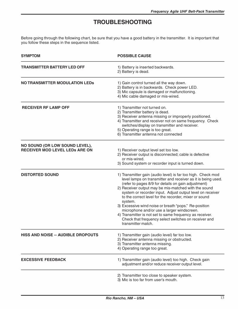
Frequency Agile UHF Belt-Pack Transmitter
TROUBLESHOOTING
Before going through the following chart be sure that you have a good battery in the transmitter It is important that you follow these steps in the sequence listed
SYMPTOM POSSIBLE CAUSE
TRANSMITTER BATTERY LED OFF 1) Battery is inserted backwards 2) Battery is dead
NO TRANSMITTER MODULATION LEDs 1) Gain control turned all the way down 2) Battery is in backwards Check power LED 3) Mic capsule is damaged or malfunctioning 4) Mic cable damaged or mis-wired
RECEIVER RF LAMP OFF 1) Transmitter not turned on 2) Transmitter battery is dead 3) Receiver antenna missing or improperly positioned 4) Transmitter and receiver not on same frequency Check
switchesdisplay on transmitter and receiver 5) Operating range is too great 6) Transmitter antenna not connected
NO SOUND (OR LOW SOUND LEVEL) RECEIVER MOD LEVEL LEDs ARE ON 1) Receiver output level set too low
2) Receiver output is disconnected cable is defective or mis-wired
3) Sound system or recorder input is turned down
DISTORTED SOUND 1) Transmitter gain (audio level) is far too high Check mod level lamps on transmitter and receiver as it is being used (refer to pages 89 for details on gain adjustment)
2) Receiver output may be mis-matched with the sound system or recorder input Adjust output level on receiver to the correct level for the recorder mixer or sound system
3) Excessive wind noise or breath ldquopopsrdquo Re-position microphone andor use a larger windscreen
4) Transmitter is not set to same frequency as receiver Check that frequency select switches on receiver and transmitter match
HISS AND NOISE -- AUDIBLE DROPOUTS 1) Transmitter gain (audio level) far too low 2) Receiver antenna missing or obstructed 3) Transmitter antenna missing 4) Operating range too great
EXCESSIVE FEEDBACK 1) Transmitter gain (audio level) too high Check gain adjustment andor reduce receiver output level
2) Transmitter too close to speaker system 3) Mic is too far from userrsquos mouth
Rio Rancho NM ndash USA 13
UM200C
SPECIFICATIONS AND FEATURES
Operating frequencies 537600 to 607900 MHz 614100 to 767900 MHz
Frequency selection 256 frequencies in 100kHz steps
RF Power output 100 mW (nominal)
Pilot tone 32764 kHz (plusmn 2Hz) 5kHz deviation
Frequency stability plusmn 0002
Deviation plusmn 75 kHz (max)
Spurious radiation 90 dB below carrier
Equivalent input noise ndash126 dBV
Input level Nominal 2 mV to 300 mV before limiting Greater than 50V maximum with limiting
Input impedance Taps provided for 500 1k 10k Ohm
Input compressor Soft compressor gt30 dB range
Gain control range 43 dB semi-log rotary control
Modulation indicators Dual LEDs indicate modulation level 12dB below limiting and at the onset of limiting
Low frequency roll-off adjustment ndash18dBoctave 35Hz to 150Hz
Controls 2 position ldquoOFF-ONrdquo slide switch for noiseless turn onturn off operation Front panel knob adjusts audio gain Recessed control on side panel
adjusts low frequency rolloff Rotary switches on side panel adjust transmitter frequency
Audio Input Jack Switchcraft 5 pin locking (TA5F)
Antenna Detachable flexible wire supplied 50 Ohm port allows connection to test equipment
Battery Precision compartment auto-adjusts to accept any known alkaline 9 Volt battery (Wersquove tried 125 different ones)
Battery Life 45 hours (alkaline) 14 hours (lithium)
Weight 63 ozs including battery
Dimensions 31 x 24 x 75 inches
Emission Designator 180KF3E
Specifications subject to change without notice
LECTROSONICS INC 14
Frequency Agile UHF Belt-Pack Transmitter
SERVICE AND REPAIR
If your system malfunctions you should attempt to correct or isolate the trouble before concluding that the equipment needs repair Make sure you have followed the setup procedure and operating instructions Check out the interconshynecting cords and then go through the TROUBLESHOOTING section in the manual
We strongly recommend that you do not try to repair the equipment yourself and do not have the local repair shop attempt anything other than the simplest repair If the repair is more complicated than a broken wire or loose connecshytion send the unit to the factory for repair and service Donrsquot attempt to adjust any controls inside the units Once set at the factory the various controls and trimmers do not drift with age or vibration and never require readjustment There are no adjustments inside that will make a malfunctioning unit start working
LECTROSONICS service department is equipped and staffed to quickly repair your equipment In-warranty repairs are made at no charge in accordance with the terms of the warranty Out-of-warranty repairs are charged at a modest flat rate plus parts and shipping Since it takes almost as much time and effort to determine what is wrong as it does to make the repair there is a charge for an exact quotation We will be happy to quote approximate charges by phone for out-of-warranty repairs
RETURNING UNITS FOR REPAIR You will save yourself time and trouble if you will follow the steps below
A DO NOT return equipment to the factory for repair without first contacting us by letter or by phone We need to know the nature of the problem the model number and the serial number of the equipment We also need a phone number where you can be reached 8 am to 4 pm (Mountain Standard Time)
B After receiving your request we will issue you a return authorization number (RA) This number will help speed your repair through our receiving and repair departments The return authorization number must be clearly shown on the outside of the shipping container
C Pack the equipment carefully and ship to us shipping costs prepaid If necessary we can provide you with the proper packing materials UPS is usually the best way to ship the units Heavy units should be ldquodouble-boxedrdquo for safe transport
D We also strongly recommend that you insure the equipment since we cannot be responsible for loss of or damage to equipment that you ship Of course we insure the equipment when we ship it back to you
Mailing address Shipping address Lectrosonics Inc Lectrosonics Inc PO Box 15900 581 Laser Rd Rio Rancho NM 87174 Rio Rancho NM 87124 USA USA
Telephones Regular (505) 892-4501 Toll Free (800) 821-1121 FAX (505) 892-6243
World Wide Web httpwwwlectrosonicscom Email saleslectrosonicscom
Rio Rancho NM ndash USA 15
LIMITED ONE YEAR WARRANTY
The equipment is warranted for one year from date of purchase against defects in materials or workmanship provided it was purchased from an authorized dealer This warranty does not cover equipment which has been abused or damaged by careless handling or shipping This warranty does not apply to used or demonstrator equipment
Should any defect develop Lectrosonics Inc will at our option repair or replace any defective parts without charge for either parts or labor If Lectrosonics Inc cannot correct the defect in your equipment it will be replaced at no charge with a similar new item Lectrosonics Inc will pay for the cost of returning your equipment to you
This warranty applies only to items returned to Lectrosonics Inc or an authorized dealer shipping costs prepaid within one year from the date of purchase
This Limited Warranty is governed by the laws of the State of New Mexico It states the entire liablility of Lectrosonics Inc and the entire remedy of the purchaser for any breach of warranty as outlined above NEITHER LECTROSONICS INC NOR ANYONE INVOLVED IN THE PRODUCTION OR DELIVERY OF THE EQUIPMENT SHALL BE LIABLE FOR ANY INDIRECT SPECIAL PUNITIVE CONSEQUENTIAL OR INCIDENTAL DAMAGES ARISING OUT OF THE USE OR INABILITY TO USE THIS EQUIPMENT EVEN IF LECTROSONICS INC HAS BEEN ADVISED OF THE POSSIBILITY OF SUCH DAMAGES IN NO EVENT SHALL THE LIABILITY OF LECTROSONICS INC EXCEED THE PURCHASE PRICE OF ANY DEFECTIVE EQUIPMENT
This warranty gives you specific legal rights You may have additional legal rights which vary from state to state
LIMITED ONE YEAR WARRANTY
LECTROSONICS INC
581 LASER ROAD RIO RANCHO NM 87124 USA wwwlectrosonicscom
November 5 2003
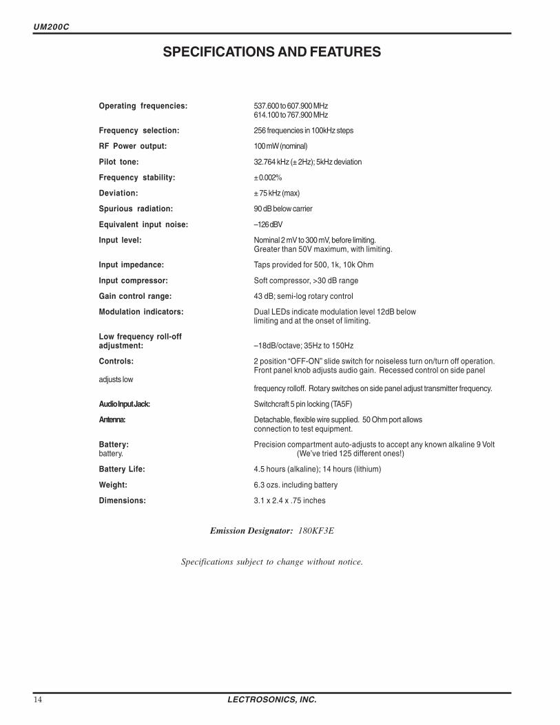
LIMITED ONE YEAR WARRANTY
The equipment is warranted for one year from date of purchase against defects in materials or workmanship provided it was purchased from an authorized dealer This warranty does not cover equipment which has been abused or damaged by careless handling or shipping This warranty does not apply to used or demonstrator equipment
Should any defect develop Lectrosonics Inc will at our option repair or replace any defective parts without charge for either parts or labor If Lectrosonics Inc cannot correct the defect in your equipment it will be replaced at no charge with a similar new item Lectrosonics Inc will pay for the cost of returning your equipment to you
This warranty applies only to items returned to Lectrosonics Inc or an authorized dealer shipping costs prepaid within one year from the date of purchase
This Limited Warranty is governed by the laws of the State of New Mexico It states the entire liablility of Lectrosonics Inc and the entire remedy of the purchaser for any breach of warranty as outlined above NEITHER LECTROSONICS INC NOR ANYONE INVOLVED IN THE PRODUCTION OR DELIVERY OF THE EQUIPMENT SHALL BE LIABLE FOR ANY INDIRECT SPECIAL PUNITIVE CONSEQUENTIAL OR INCIDENTAL DAMAGES ARISING OUT OF THE USE OR INABILITY TO USE THIS EQUIPMENT EVEN IF LECTROSONICS INC HAS BEEN ADVISED OF THE POSSIBILITY OF SUCH DAMAGES IN NO EVENT SHALL THE LIABILITY OF LECTROSONICS INC EXCEED THE PURCHASE PRICE OF ANY DEFECTIVE EQUIPMENT
This warranty gives you specific legal rights You may have additional legal rights which vary from state to state
LIMITED ONE YEAR WARRANTY
LECTROSONICS INC
581 LASER ROAD RIO RANCHO NM 87124 USA wwwlectrosonicscom
November 5 2003