Embed Size (px)
Citation preview

1
Frequency Response of a Circuit
Z. Aliyazicioglu
Electrical and Computer Engineering DepartmentCal Poly Pomona
ECE307
ECE 307-4 2
The Laplace TransformFrequency Response of a Circuit
Analysis of a circuit with varying frequency of a sinusoidal sources is called the frequency response of a circuit
Some Preliminaries
, Frequency selection in the circuits are called filters because of their ability to filter out certain input signals on the basis of frequency
FilterFilterInput signal Output signal

2
ECE 307-4 3
Frequency Response of a Circuit
We remember that the transfer function is the output voltage to the input voltage of a circuit in s-domain is.
0( )( )( )i
V sH sV s
=
0( )( )( )i
V jH jV j
ωωω
=
Using sinusoidal source, the transfer function will be the magnitude and phase of output voltage to the magnitude and phase of input voltage of a circuit .
In this case we will use (jω) instead of s .
Some Preliminaries
ECE 307-4 4
Frequency Response of a Circuit
Using transfer function of circuit, we plot a frequency response of the circuit for both amplitude and phasewith changing source frequency
One graph of |H(jω)| versus frequency jω. It is called the Magnitude plot.One graph of θ(jω) versus frequency ω. It is called the Phase Angle plot
Frequency Response
Passband
ωc
ω
|H(jω)|
Stopband
ωc
ωθ(jω)
θ(jωc)
ωc : Cutoff frequency

3
ECE 307-4 5
Frequency Response of a Circuit
A Low-Pass filter passes signals at frequencies lower than the cutoff frequency from the input to the output
Filter
A High-Pass filter passes signals at frequencies higher than the cutoff frequency from the input to the output
Passbandω
|H(jω)|
Stopband
ωcθ(jω)
θ(jωc)
ωc Cutoff frequency
Passbandω
|H(jω)|
Stopband
ωcθ(jω)
θ(jωc)
Ideal Low-Pass Filter Ideal High-Pass Filter
00
ECE 307-4 6
Passband
Frequency Response of a CircuitFilter
A Band-reject filter passes signals outside the band defined by two cutoff frequencies from the input to the output
Passbandω
|H(jω)|
Stopband
ωc2θ(jω)θ(jωc1)
ωc Cutoff frequency
Passband
ω
|H(jω)|
Stopband
θ(jω)
θ(jωc1)
Ideal Band-Pass Filter Ideal Band-Reject Filter
Stopband
ωc1
θ(jωc1)
ωc2ωc1θ(jωc1)
0
A Band-Pass filter passes signals within the band defined by two cutoff frequencies from the input to the output

4
ECE 307-4 7
Frequency Response of a Circuit
ω = max1( )2cH j H
The transfer function magnitude is decreased by the factor 1/√2 from its maximum value is called cutoff frequency
Cutoff Frequency
|Hmax | is the maximum magnitude of the transfer function
ECE 307-4 8
Frequency Response of a Circuit
A Serial RL CircuitLow-Pass Filter
( )
RLH s RsL
=+
0( )( )i
V s RV s sL R
=+
( )
RLH j RjL
ωω
=+
To find frequency response, substitute s=jω in equation
22
( )
RLH jRL
ω
ω
= +
1( ) tan LjRωθ ω − = −
Phase ResponseMagnitude Response
RVi(s)
-
+
sL1 2
Vo(s)
5
ECE 307-4 9
Frequency Response of a Circuit
When ω=0
22
( 0) 1
0
RLH jRL
= = +
1 0( 0) tan 0LjR
θ − = − =
To find Cutoff Frequency
When ω=∞
22
( ) 0
RLH jRL
∞ = = ∞ +
1( ) tan 90LjR
θ − ∞ ∞ = − = −
22
1( )2c
c
RLH jRL
ω
ω
= = +
cRL
ω =
A Serial RL Circuit
Result
ECE 307-4 10
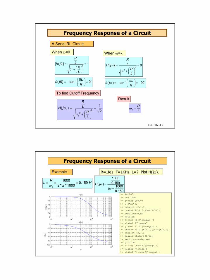
Frequency Response of a Circuit
Example
1000 0.1592 * *1000c
RL Hω π
= = =
R=1KΩ F=1KHz. L=? Plot H(jω). 10000.159( ) 1000
0.159
H jj
ωω
=+
>> R=1000;>> L=0.159;>> f=0:25:10000;>> w=2*pi*f;>> subplot (2,1,1)>> h=abs((R/L)./(j*w+(R/L)));>> semilogx(w,h)>> grid on>> title('|H(j\omega)|')>> xlabel ('\omega')>> ylabel ('|H(j\omega)|')>> theta=angle((R/L)./(j*w+(R/L)));>> subplot (2,1,2)>> degree=theta*180/pi;>> semilogx(w,degree)>> grid on>> title('\theta(j\omega)')>> xlabel('\omega')>> ylabel('\theta(j\omega)')

6
ECE 307-4 11
Frequency Response of a Circuit
Example
/( )/
R LH ss R L
=+
R=1KΩ F=1KHz. L=? Plot H(jω).
>> syms s
>> n=[0 1000/0.159];
>> d=[1 1000/0.159];
>> g=tf(n,d)
Transfer function:
6289
--------
s + 6289
>> bode (g)
>> grid on
Matlab
ECE 307-4 12
Frequency Response of a Circuit
V11Vac0Vdc
L1
0.159H1 2
R1
1k
VV
0
Fr e q u e n c y
1 0 0 Hz 3 0 0 Hz 1 . 0 KHz 3 . 0 KHz 1 0 KHz 3 0 KHz 1 0 0 KHzV( L1 : 2 ) V( V1 : +)
0 V
0 . 5 V
1 . 0 V
Example
fc=1KHz

7
ECE 307-4 13
Frequency Response of a Circuit
A Serial RC CircuitLow-Pass Filter
1
( ) 1RCH s
sRC
=+
0
1( )
1( )i
V s sCV s R
sC
=+
1
( ) 1RCH j
jRC
ωω
=+
To find frequency response, substitute s=jω in equation
22
1
( )1
RCH j
RC
ω
ω
= +
( )1( ) tanj RCθ ω ω−= −
Phase ResponseMagnitude Response
-Vo(s)+
R
1/sCVi(s)
ECE 307-4 14
Frequency Response of a Circuit
When ω=0
22
1
( 0) 110
RCH j
RC
= = +
( )1( 0) tan 0 0j RCθ −= − =
To find Cutoff Frequency
When ω=∞
22
1
( ) 01
RCH j
RC
∞ = = ∞ +
( )1( ) tan 90j RCθ −∞ = − ∞ = −
22
11( )21
c
c
RCH j
RC
ω
ω
= = +
1c RC
ω =
A Serial RC Circuit
Result

8
ECE 307-4 15
Frequency Response of a Circuit
Example A series RC low-pass filter cutoff frequency is 8KHz. R=10KΩ Find the capacitor value
1c RC
ω =1c
CRω
= 1 1.992 * * 8000 10000
C nFxπ
= =
Example A series RL low-pass filter cutoff frequency is 2KHz. R=5KΩ Find the inductor value. Find |H(jω)| at 50 KHz?
cRL
ω =c
RLω
=5000 2.52000
L H= =
50 2 22 2
50002.5( ) 0.0635
5000(2 * * 50000)2.5
KHz
RLH jRL
ω
ω π
= = = + +
ECE 307-4 16
Frequency Response of a Circuit
Example A series RC low-pass filter cutoff frequency is 8KHz. R=10KΩ, C=1.99 nF
r=10000;c=19.9*10^-9;
f=0:25:100000;w=2*pi*f;h=abs((1/(r*c))./(j*w+1/(r*c)));subplot (2,1,1)semilogx(w,h)grid ontitle('|H(j\omega)')xlabel ('\omega')ylabel ('|H(j\omega)')theta=angle((1/(r*c))./(j*w+1/(r*c)));subplot (2,1,2)degree=theta*180/pi;semilogx (w, degree)grid ontitle('\theta(j\omega)')xlabel('\omega')ylabel('\theta(j\omega)')

9
ECE 307-4 17
Frequency Response of a Circuit
V
R1
10k
C1
1.99n
0
V
V11Vac0Vdc
Fr e q u e n c y
1 0 0 Hz 1 . 0 KHz 1 0 KHz 1 0 0 KHz 1 . 0 MHzV( R1 : 1 ) V( V1 : +)
0 V
0 . 5 V
1 . 0 V
Example
fc=8KHz =1( )2cH f
ECE 307-4 18
Frequency Response of a Circuit
A Serial RC CircuitHigh-Pass Filter
( ) 1sH s
sRC
=+
0( )1( )i
V s RV s R
sC
=+
( ) 1jH j
jRC
ωωω
=+
To find frequency response, substitute s=jω in equation
22
( )1
H j
RC
ωω
ω
= +
( )1( ) 90 tanj RCθ ω ω−= −
Phase ResponseMagnitude Response
1/sC
Vi(s)-
R Vo(s)+

10
ECE 307-4 19
Frequency Response of a Circuit
When ω=0
22
0( 0) 010
H j
RC
= = +
1 0( 0) 90 tan 90jRC
θ − = − =
To find Cutoff Frequency
When ω=∞
22
( ) 11
H j
RC
∞∞ = =
∞ +
1( ) 90 tan 0jRC
θ − ∞ ∞ = − =
22
1( )21
cc
c
H j
RC
ωω
ω
= = +
1c RC
ω =
A Serial RC Circuit
Result
ECE 307-4 20
Frequency Response of a Circuit
A Serial RL CircuitHigh-Pass Filter
( ) sH s RsL
=+
0( )( )i
V s sLV s sL R
=+
( ) jH j RjL
ωωω
=+
To find frequency response, substitute s=jω in equation
22
( )H jRL
ωω
ω
= +
1( ) 90 tan LjRωθ ω − = −
Phase ResponseMagnitude Response
Vi(s) sL
1
2 -Vo(s)
+
R

11
ECE 307-4 21
Frequency Response of a Circuit
When ω=0
22
0( 0) 0
0
H jRL
= = +
1 0( 0) 90 tan 90LjR
θ − = − =
To find Cutoff Frequency
When ω=∞
22
( ) 1H jRL
∞∞ = =
∞ +
1( ) 90 tan 0LjR
θ − ∞ ∞ = − =
22
1( )2
cc
c
H jRL
ωω
ω
= = +
cRL
ω =
A Serial RL Circuit
Result
ECE 307-4 22
Frequency Response of a Circuit
Example Define R and L values for a high pass filter with a cutoff frequency of 10KHz. Find |H(jω)|at 5 KHz
Let
We can’t calculate R and L values independently. We can select R or L values then define the other
1R K= Ω
c
RLω
= 1000 15.92 * *10000
L mHπ
= =
5 2 22 2
2 * * 5000( ) 0.44691000(2 * * 5000)
0.0159
KHzH jRL
ω πω
ω π
= = = + +
cRL
ω =
Result

12
ECE 307-4 23
Frequency Response of a Circuit
Example A RL high pass filter with a cutoff frequency of 10KHz. 1R K= Ω 1000 15.9
2 * *10000L mH
π= =
R=1000;L=15.9*10^-3;
f=0:25:70000;w=2*pi*f;h=abs((j*w)./(j*w+R/L));subplot (2,1,1)semilogx(w,h)grid ontitle('|H(j\omega)')xlabel ('\omega')ylabel ('|H(j\omega)')theta=angle((j*w)./(j*w+R/L));subplot (2,1,2)plot (w, theta)degree=theta*180/pi;semilogx (f, degree)grid ontitle('\theta(j\omega)')xlabel('\omega')ylabel('\theta(j\omega)')
ECE 307-4 24
Frequency Response of a Circuit
V11Vac0Vdc
V
L2
15.9mH
1
2
R1
1K V
0
Fr e q u e n c y
1 0 0 Hz 1 . 0 KHz 1 0 KHz 1 0 0 KHz 1 . 0 MHzV( R1 : 2 ) V( V1 : +)
0 V
0 . 5 V
1 . 0 V
fc=8KHz
Example
=1( )2cH f

13
ECE 307-4 25
Frequency Response of a Circuit
L2
15.9mH
1
2
V11Vac0Vdc
VPVP
0
R1
1K
Plotting phase: Take the probe Phase of Voltage, which is under Pspice, Markers, and Advanced. Marked the node you want to see phase
Fr e q u e n c y
1 0 0 Hz 1 . 0 KHz 1 0 KHz 1 0 0 KHz 1 . 0 MHzVP( V1 : +) VP( R1 : 2 )
0 d
5 0 d
1 0 0 d
fc=8KHz =( ) 45cH f
ECE 307-4 26
Frequency Response of a Circuit
Example Let’s place load resister in parallel to inductor in RL high-pass filter shown in the figure a. Find the transfer functionb. Rs=RL=1KΩ, find L value for cutoff frequency at
10KHz.
cRKL
ω =
0( )( )
L
L
Li
L
R sLV s R sL
R sLV s RR sL
+=
++
( )
L
L
L
L
R sR R KsH s R R Rs s KR R L L
+= =
+ ++
L
L
RKR R
=+
where 1 0.51 1
K = =+
10.5 7.952 * *10c
RL K mHω π
= = =
Result
-
Vo(s)
R
+sL
1
2
Vi(s) RL

14
ECE 307-4 27
Frequency Response of a Circuit
Example Rs=RL=1KΩ, L=7.95 mH High-pass filter cutoff frequency at 10KHz.
( ) j KH j Rj KL
ωωω
=+
R=1000;RL=1000;L=7.95*10^-3;K=RL/(R+RL)
f=0:25:70000;w=2*pi*f;h=abs((j*w*K)./(j*w+K*R/L));subplot (2,1,1)semilogx(w,h)grid ontitle('|H(j\omega)')xlabel ('\omega')ylabel ('|H(j\omega)')theta=angle((j*w*K)./(j*w+K*R/L));subplot (2,1,2)plot (w, theta)degree=theta*180/pi;semilogx (f, degree)grid ontitle('\theta(j\omega)')xlabel('\omega')ylabel('\theta(j\omega)')grid on