Embed Size (px)
Citation preview
Freshman Design Team 24 Drexel University tDEC Program
Philadelphia, PA 19104
May 14, 2004
Dr. Bahram Nabet University Crossings 130 Drexel University Philadelphia, PA 19104 Dear Dr. Bahram Nabet,
We are pleased to submit to you the final report by Team 24. We feel that this report adequately reflects the work we have put into it and hope that you will find it both informative and enjoyable.
With the allotted time for the Freshman Design Project, we have completed our project to the best of our ability. We have used the skills that we have developed throughout the tDEC curriculum to complete our project. Our team has successfully worked together researching how to help people with disabilities navigate more safely. With this research we were able to create a professional proposal and develop a working prototype of our design. Our final design, BackAssist, is a product that is able to accurately detect not only objects but stairs as well.
Team 24 gratefully thanks you for your time. Please feel free to contact us with comments or questions about our project, BackAssist.
Sincerely,
Isabelle Harroch Daniel Lofaro
Kevin Lynch Alexander Silverman
Stephanie Toth
A FINAL REPORT
DESIGN TEAM NO. 24 SUBMITTED TO Dr. Bahram Nabet Dr. Michael O’Shea Lisa Farley
AND THE TDEC 132 PROJECT DESIGN FACULTY OF DREXEL UNIVERSITY
ENTITLED: BackAssist: A Proximity Sensor for Wheelchairs TEAM MEMBERS/HUM SECTION/INSTRUCTOR
Team Members
Humanties Section
Humanities Advisor
Isabelle Harroch 300 Farley Daniel Lofaro 008 O’Shea Kevin Lynch 009 McCann
Alexander Silverman 015 Watts Stephanie Toth 016 Finegan
Submitted in partial fulfillment of the requirements for the Engineering Design and Laboratory, TDEC 132, Design Project
Submitted on May 14, 2004
Table of Contents Table of Figures ................................................................................................................... i Abstract ............................................................................................................................... ii Executive Summary ........................................................................................................... iii Introduction......................................................................................................................... 1
Problem Background .............................................................................................. 1 Problem Statement .................................................................................................. 2 Criteria .................................................................................................................... 3 Constraints .............................................................................................................. 3
Survey of Literature ............................................................................................................ 4 The Solution........................................................................................................................ 5
The Prototype.......................................................................................................... 5 Work Done Towards Solution ................................................................................ 5 Layout of the BackAsssist ...................................................................................... 6 Visual Display......................................................................................................... 7
Discussions and Conclusions.............................................................................................. 8 Validity and Errors.................................................................................................. 8 Costs and Benefits................................................................................................... 9
Future Work ...................................................................................................................... 10 References......................................................................................................................... 11
Works Cited .......................................................................................................... 11 Works Consulted................................................................................................... 12
Acknowledgements........................................................................................................... 13 Appendixes ....................................................................................................................... 14
Appendix A – Budget ........................................................................................... 15 Appendix B - Components.................................................................................... 18 Appendix C – Basic Stamp 2SX Microprocessor................................................. 19 Appendix D – Devantech SRF04 Ultrasonic Range Sensor................................. 20 Appendix E - BackAssist Prototype ..................................................................... 21 Appendix F – CAD Drawings............................................................................... 22 Appendix G – BackAssist Prototype Schematics ................................................. 24 Appendix H – BackAssist Final Schematic .......................................................... 25 Appendix I – BackAssist Flow Charts.................................................................. 26
Detecting Objects...................................................................................... 26 Detecting Stairs......................................................................................... 27
Appendix J – BackAssist Prototype Source Code ................................................ 28 Appendix L – Qualifications................................................................................. 33
i
Table of Figures Figure 1: MAid traversing a train concourse in Ulm, Germany (Prassler 44).................... 2 Figure 2. Functionality of a generic sonar sensor (Lee 2) .................................................. 4 Figure 3: Alignment of sensors on a wheelchair ................................................................ 7 Figure 4: Top panel of visual display ................................................................................. 8 Figure 5: BS 2SX Microprocessor (Parallax) ................................................................... 19 Figure 6: BS2SX OEM Module (Parallax)....................................................................... 19 Figure 7: Timing diagram for the SRF04 (Robot Electronics) ......................................... 20 Figure 8: Connections for the SRF04 (Robot Electronics)............................................... 20 Figure 9: Beam Pattern for the SRF04 (Acroname) ......................................................... 20 Figure 10: A photograph of the BackAssist prototype ..................................................... 21 Figure 11: Sensor Front .................................................................................................... 22 Figure 12: Sensor Side ...................................................................................................... 22 Figure 13: Visual Display Top.......................................................................................... 23 Figure 14: Visual Display, Bottom ................................................................................... 23 Figure 15: Visual Display Side ......................................................................................... 23 Figure 16: BackAssist Prototype Schematics ................................................................... 24 Figure 17: BackAssist Schematics.................................................................................... 25 Figure 18: Flow chart for detecting objects ...................................................................... 26 Figure 19: Flow chart for detecting stairs ......................................................................... 27
ii
Abstract The BackAssist is a device that monitors the area behind a wheelchair for any
obstructions or a sudden change in elevation of the terrain. The design utilizes the Basic
Stamp 2SX (BS2SX) microprocessor to control four ultrasonic sensors and a visual
output that relays warnings to the operator. Two sensors are placed in the back above
each of the rear wheels on the wheelchair at an elevation of 0.6m and at an angle of 55°
to the horizontal. Two more ultrasonic sensors are placed above the other sensors at an
adjustable height with an angle of 35° to the back of the wheelchair.The BackAssist is
able to sense an object that is between 92cm to 3cm from the rear of the wheelchair. It is
also able to detect a sudden change in elevation of 7cm or greater by use of a custom
program that uses derivatives to look for sudden changes in the terrain.
iii
Executive Summary Every year, 1 out of 200 people become disabled and have to rely on a wheelchair
to get around. Unfortunately, wheelchair users are still limited by narrow passageways,
tight corners, and various obstacles that are not always visible to them. Many people who
rely on a wheelchair cannot see what is behind them. When a person in a wheelchair is
turning around or simply moving backwards, there are many obstacles that they have to
encounter. Such hazards that could cause potential injury are tables, chairs, other people,
and, most dangerously, flights of stairs. This serious problem demands a solution that will
help disabled people avoid hazards.
Our solution to this problem is a product called "BackAssist." The BackAssist is
able to detect an object in the path of the wheelchair 100% of the time. It is the perfect
device for detecting not only objects behind a wheelchair but also dangerous flights of
stairs. Its sensors will provide a warning through lights that are simple to understand. The
BackAssist is an accessory that can easily be attached to the arm of a wheelchair.
The BackAssist is also cost effective. A short term production run of 1000 units,
would cost $152,000. This includes component costs, development time, and
manufacturing costs. Including a 50% overhead, the total cost would increase to
$230,000. The BackAssist will be sold for $250.00 per unit, yielding a minimum profit of
$20,000. Assuming there is no additional overhead, the total profit would be $90,000.
What separates the BackAssist from other wheelchair safety devices is that the
BackAssist is the only product on the market that detects stairs behind a wheelchair. The
product is cost effective to produce and gives an accurate reading that is simple to
understand.
1
Introduction
Problem Background Each year, thousands of people are forced to use wheelchairs due to illnesses and
accidents. Current scientific studies state that 1 out of every 200 Americans suffers from
mobility or activity handicaps. At present, an estimated 1.8 million Americans depend
upon wheelchairs (Haseltine 1). To help alleviate some of the difficulties people with
disabilities face, a wide variety of wheelchairs and accessories have been created. Even
with an increase of assistive technology, people in wheelchairs still have difficulties
navigating through narrow and crowded areas. Not only do these issues cause daily life to
become burdensome, they also constitute a danger to the safety and welfare of the
wheelchair operator.
Wheelchairs provide an important degree of independence for those they assist.
However, this degree of independence can be limited if the wheelchair is required to
traverse obstacles which are not always visible, such as tight corners, sidewalks, or stairs.
Because of these dangerous conditions people with disabilities face every day, engineers
have been working on projects with the sole purpose of ensuring the safety of wheelchair
operators by increasing the stability and control of wheelchairs. Currently, there are a
variety of methods of control for wheelchair operation such as simple joysticks, breath
controls, or head position controls. In addition to a variety of control systems, there are
some innovations which improve other aspects of wheelchairs. For example, Degonda-
Rehab S.A., a Swiss wheelchair manufacturer, was awarded a U.S. patent for their
wheelchair design that incorporated small wheels that helped with stability and mobility.
In addition to stabilizing wheels, it possesses wheels that allow the chair to climb curbs
and other objects. (Degonda 1). In an issue of Innovations, the quarterly magazine of the
Industrial Designers Society of America, several innovations for wheelchairs are
described such as anti-tipping devices, voice controlled wheelchairs, stair climbing
wheelchairs, and many more (Hannah 1).
At present, there are some designs, such as the Power Rolls IV, that can be
considered successful past improvements to the wheelchair. The Power Rolls IV by
Invacare Corporation was the first to introduce dynamic braking, regenerative braking,
2
and self-correcting steering to maintain constant speed and direction on uneven surfaces
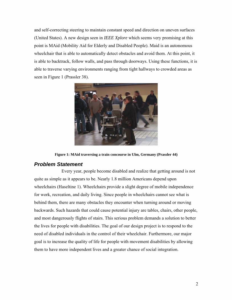
(United States). A new design seen in IEEE Xplore which seems very promising at this
point is MAid (Mobility Aid for Elderly and Disabled People). Maid is an autonomous
wheelchair that is able to automatically detect obstacles and avoid them. At this point, it
is able to backtrack, follow walls, and pass through doorways. Using these functions, it is
able to traverse varying environments ranging from tight hallways to crowded areas as
seen in Figure 1 (Prassler 38).
Figure 1: MAid traversing a train concourse in Ulm, Germany (Prassler 44)
Problem Statement Every year, people become disabled and realize that getting around is not
quite as simple as it appears to be. Nearly 1.8 million Americans depend upon
wheelchairs (Haseltine 1). Wheelchairs provide a slight degree of mobile independence
for work, recreation, and daily living. Since people in wheelchairs cannot see what is
behind them, there are many obstacles they encounter when turning around or moving
backwards. Such hazards that could cause potential injury are tables, chairs, other people,
and most dangerously flights of stairs. This serious problem demands a solution to better
the lives for people with disabilities. The goal of our design project is to respond to the
need of disabled individuals in the control of their wheelchair. Furthermore, our major
goal is to increase the quality of life for people with movement disabilities by allowing
them to have more independent lives and a greater chance of social integration.
3
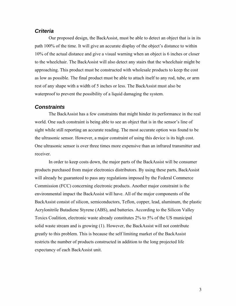
Criteria Our proposed design, the BackAssist, must be able to detect an object that is in its
path 100% of the time. It will give an accurate display of the object’s distance to within
10% of the actual distance and give a visual warning when an object is 6 inches or closer
to the wheelchair. The BackAssist will also detect any stairs that the wheelchair might be
approaching. This product must be constructed with wholesale products to keep the cost
as low as possible. The final product must be able to attach itself to any rod, tube, or arm
rest of any shape with a width of 5 inches or less. The BackAssist must also be
waterproof to prevent the possibility of a liquid damaging the system.
Constraints The BackAssist has a few constraints that might hinder its performance in the real
world. One such constraint is being able to see an object that is in the sensor’s line of
sight while still reporting an accurate reading. The most accurate option was found to be
the ultrasonic sensor. However, a major constraint of using this device is its high cost.
One ultrasonic sensor is over three times more expensive than an infrared transmitter and
receiver.
In order to keep costs down, the major parts of the BackAssist will be consumer
products purchased from major electronics distributors. By using these parts, BackAssist
will already be guaranteed to pass any regulations imposed by the Federal Commerce
Commission (FCC) concerning electronic products. Another major constraint is the
environmental impact the BackAssist will have. All of the major components of the
BackAssist consist of silicon, semiconductors, Teflon, copper, lead, aluminum, the plastic
Acrylonitrile Butadiene Styrene (ABS), and batteries. According to the Silicon Valley
Toxics Coalition, electronic waste already constitutes 2% to 5% of the US municipal
solid waste stream and is growing (1). However, the BackAssist will not contribute
greatly to this problem. This is because the self limiting market of the BackAssist
restricts the number of products constructed in addition to the long projected life
expectancy of each BackAssist unit.
4
Survey of Literature One of the many difficulties users of wheelchairs must face is the navigation of
narrow or cluttered areas. Recently, there has much activity regarding the research and
design of new innovations to help wheelchair users. Disability World and Adaptive
Environments are two non-profit organizations dedicated to enhancing the quality of life
for people of all ages and disabilities. These organizations list many innovations such as
new high-powered wheelchairs and accessories. These new high-powered wheelchairs
ensure an accurate stability of the wheelchair.
One of the prominent developers in versatile microprocessors is Parallax Inc. The
company produces a variety of processors designed for both consumer and industrial use.
Currently their most popular line of processors is the Basic Stamp 2SX, also know as the
BS2SX. The BS2SX is used because of its relatively high processing power with a range
of clock speeds from 20 MHz to 50 MHz. The microprocessor can also withstand
temperatures ranging from -40ºC to 85ºC (Parallax, Inc. 1). It has been used in the past by
NASA to monitor and record the growth rate of bacteria in zero gravity (Droter 1). In
addition, the BS2SX is also able to control a variety of 5 volts components such as
sensors, motors, and more. (See Appendix C for more information.)
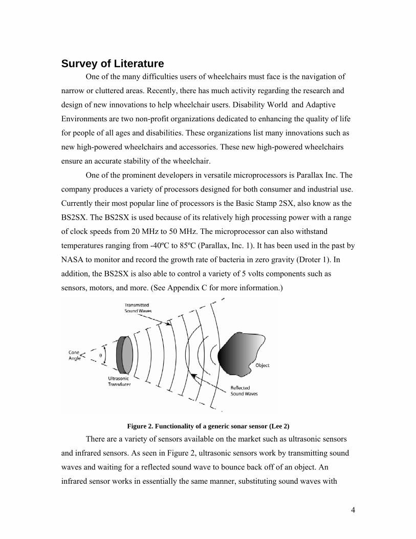
Figure 2. Functionality of a generic sonar sensor (Lee 2)
There are a variety of sensors available on the market such as ultrasonic sensors
and infrared sensors. As seen in Figure 2, ultrasonic sensors work by transmitting sound
waves and waiting for a reflected sound wave to bounce back off of an object. An
infrared sensor works in essentially the same manner, substituting sound waves with
5
infrared light. The Devantech SRF04 Ultrasonic Range Finder is one example of an
ultrasonic sensor. It has a separate transmitter and receiver allowing for accurate
detection at small distances. Using a specific frequency of 40 kHz to reduce false echoes,
the SRF04 is able to offer precise ranging information from roughly 3 centimeters to 3
meters. Because the sensor requires only a minimal voltage of 5 volts, it works well with
the BS2SX microprocessor (Lee 2). (See appendix D for more information.)
The Solution
The Prototype Throughout the design process, our team had gone through several different
designs until the final solution of what is essentially a warning device was decided upon.
We had to decide how we would detect objects and sudden drops in the terrain, how the
system would respond to these hazards, and how this would be communicated to the user.
By going through the design process and making these decisions, a prototype was
created. The prototype succeeded in meeting all of the criteria the BackAssist would have
to meet while still following the constraints. (See Appendix E for more information on
the prototype.)
Work Done Towards Solution In order to build this prototype and come up with a design for the final solution,
several steps had to be taken. The first task that had to be completed is a safe method of
determining the locations of objects and sudden drops. An obvious solution to this
problem was to use mirrors mounted on the wheelchair. However, mirrors can distort a
person’s sense of distance, as stated on side view mirrors of automobiles. Furthermore,
mirrors cannot reflect everything behind the wheelchair, leaving viewers with a blind
spot. In order to fully understand what is surrounding the wheelchair, a more
technological solution was decided upon—wave transmitters and receivers.
To detect objects around the wheelchair, two types of sensors under consideration
were ultrasonic sensors and infrared sensors. Infrared sensors emit infrared light that is
reflected off of objects and is able to be picked up by the receiver. However, infrared,
like visible light, is absorbed by black objects, leaving no signal to be sent back to the
6
receiver. An ultrasonic sensor, on the other hand, does not have this problem. Using this
information, we decided to use ultrasonic sensors because of their reliability over infrared
sensors in certain situations.
The next stage of our design project involved taking the results obtained by the
sensors and determining what to do with them. The original design for the BackAssist
called for an active response system to essentially decide what is hazardous to a person
with disabilities and what is not. There are many advantages to an active system like this.
For example, it is easier on the wheelchair operator because it can judge relative
distances and velocities of objects more accurately than the user can in nearly all
conditions. However, this active system can make mistakes that could be harmful to the
operator. For example, the system could malfunction, leading users to a dangerous
location. It could also interpret false readings, therefore creating jerking motions. Another
problem with this system is that, after time, the user would begin to rely too heavily on
the machine’s judgment and ignore the surroundings. Because of these negative aspects
of the active system, a passive system was decided to be safer for wheelchair operators. A
passive system presents users with all of the information received by the sensors and
allows them to make the decision of how to interpret that information.
A passive system relies on a way to convey information to users. Two possible
solutions to providing this information is an audible warning or a visual display. The
visual display was chosen over the audible warning because it would not be as irritating
to the user or others nearby. Furthermore, sound is more difficult to detect than light
because it can be confused for other beeping devices such as other vehicles, cell phones,
or even watches.
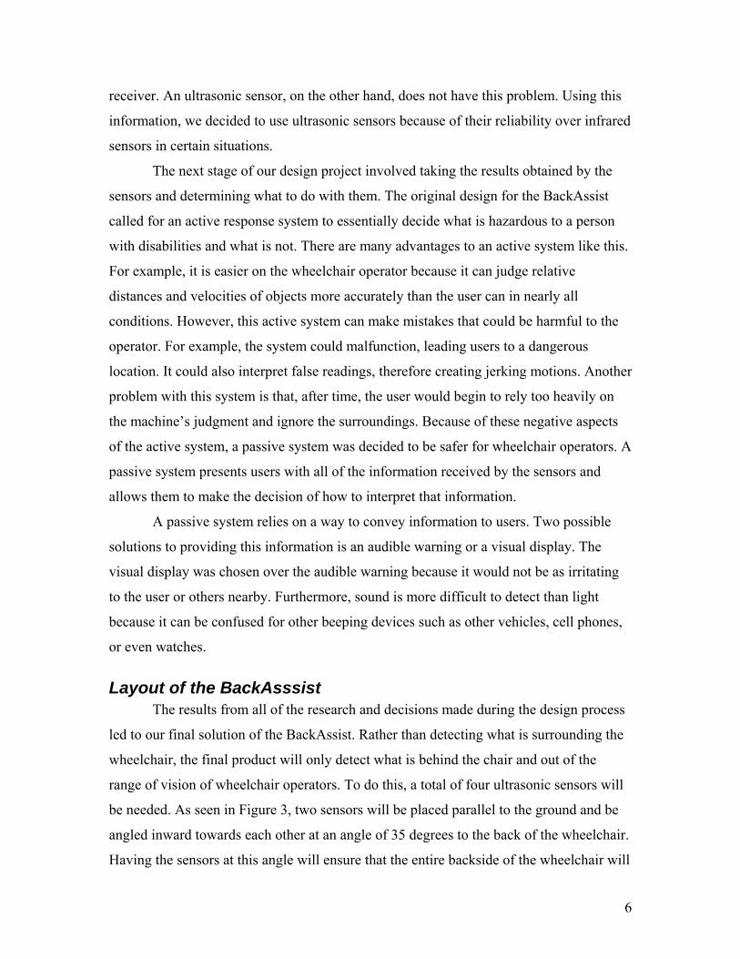
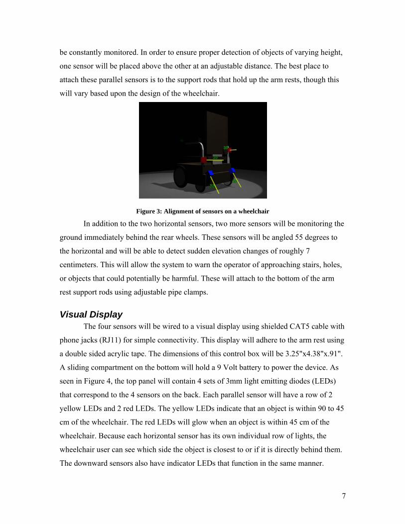
Layout of the BackAsssist The results from all of the research and decisions made during the design process
led to our final solution of the BackAssist. Rather than detecting what is surrounding the
wheelchair, the final product will only detect what is behind the chair and out of the
range of vision of wheelchair operators. To do this, a total of four ultrasonic sensors will
be needed. As seen in Figure 3, two sensors will be placed parallel to the ground and be
angled inward towards each other at an angle of 35 degrees to the back of the wheelchair.
Having the sensors at this angle will ensure that the entire backside of the wheelchair will
7
be constantly monitored. In order to ensure proper detection of objects of varying height,
one sensor will be placed above the other at an adjustable distance. The best place to
attach these parallel sensors is to the support rods that hold up the arm rests, though this
will vary based upon the design of the wheelchair.
Figure 3: Alignment of sensors on a wheelchair
In addition to the two horizontal sensors, two more sensors will be monitoring the
ground immediately behind the rear wheels. These sensors will be angled 55 degrees to
the horizontal and will be able to detect sudden elevation changes of roughly 7
centimeters. This will allow the system to warn the operator of approaching stairs, holes,
or objects that could potentially be harmful. These will attach to the bottom of the arm
rest support rods using adjustable pipe clamps.
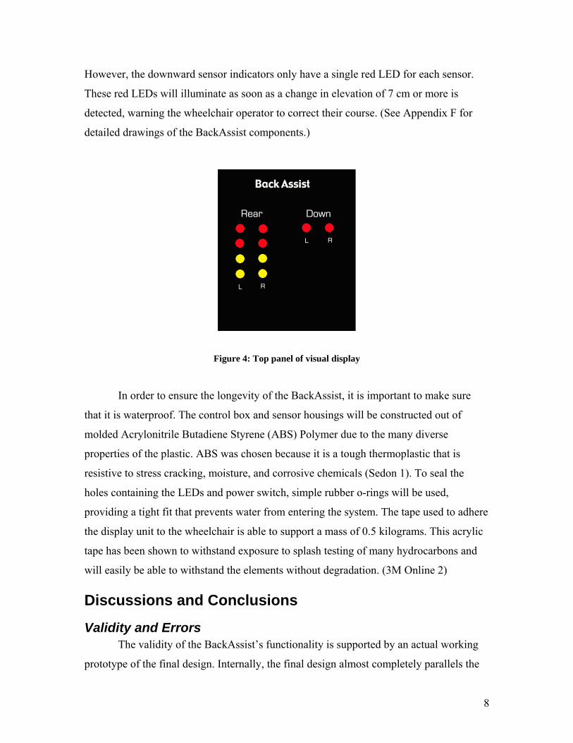
Visual Display The four sensors will be wired to a visual display using shielded CAT5 cable with
phone jacks (RJ11) for simple connectivity. This display will adhere to the arm rest using
a double sided acrylic tape. The dimensions of this control box will be 3.25"x4.38"x.91".
A sliding compartment on the bottom will hold a 9 Volt battery to power the device. As
seen in Figure 4, the top panel will contain 4 sets of 3mm light emitting diodes (LEDs)
that correspond to the 4 sensors on the back. Each parallel sensor will have a row of 2
yellow LEDs and 2 red LEDs. The yellow LEDs indicate that an object is within 90 to 45
cm of the wheelchair. The red LEDs will glow when an object is within 45 cm of the
wheelchair. Because each horizontal sensor has its own individual row of lights, the
wheelchair user can see which side the object is closest to or if it is directly behind them.
The downward sensors also have indicator LEDs that function in the same manner.
8
However, the downward sensor indicators only have a single red LED for each sensor.
These red LEDs will illuminate as soon as a change in elevation of 7 cm or more is
detected, warning the wheelchair operator to correct their course. (See Appendix F for
detailed drawings of the BackAssist components.)
Figure 4: Top panel of visual display
In order to ensure the longevity of the BackAssist, it is important to make sure
that it is waterproof. The control box and sensor housings will be constructed out of
molded Acrylonitrile Butadiene Styrene (ABS) Polymer due to the many diverse
properties of the plastic. ABS was chosen because it is a tough thermoplastic that is
resistive to stress cracking, moisture, and corrosive chemicals (Sedon 1). To seal the
holes containing the LEDs and power switch, simple rubber o-rings will be used,
providing a tight fit that prevents water from entering the system. The tape used to adhere
the display unit to the wheelchair is able to support a mass of 0.5 kilograms. This acrylic
tape has been shown to withstand exposure to splash testing of many hydrocarbons and
will easily be able to withstand the elements without degradation. (3M Online 2)
Discussions and Conclusions
Validity and Errors The validity of the BackAssist’s functionality is supported by an actual working
prototype of the final design. Internally, the final design almost completely parallels the
9
prototype and ensures that the BackAssist will function as described. Furthermore,
documentation of tests performed on the components of the final design, specifically the
ultrasonic sensor and the microprocessor, shows that the BackAssist’s design is able to
function as described. Though the design is valid, there are still flaws present. An
important error to be aware of is due to the nature of the ultrasonic sensor and its inability
to sense objects on the ground accurately at an angle of less than 45° to the horizontal.
However, the positioning of the sensors on the wheelchair is assumed to be the most
effective and efficient in warning the operator of dangers and will eliminate the potential
of false readings from the sensor.
Costs and Benefits In order to produce the BackAssist, several costs must be taken into consideration.
Many factors influence the final cost of producing the BackAssist such as the cost of all
materials used, the cost of materials and employees needed for production, and the cost of
development. Assuming a first production run of 1000 units, the total cost of all materials
is $152,000 based off of price quotes from major electronics distributors. The production
of the BackAssist requires 1 supervisor and 5 employees to prepare the microprocessor,
solder the project, assemble the device, wire the system and test the quality of each unit.
The yearly salary for each electronics assembler is $33,000 and $34,500 for the
supervisor (salary.com). Estimating the total production time to be 650 man-hours, the
total cost of employees will be $10,700. The development cost with 5 engineers salaried
at $55,000 per year performing 300 man-hours is calculated to be $9,500. The total cost
of production, including 50% overhead, will be $230,000. With an estimated selling price
of $250 per unit, the total profit made will range from $20,000 to a maximum of $90,000
if no overhead is needed. (See Appendix A for more information.)
To justify the cost of the BackAssist the benefits of the system must be evaluated.
The BackAssist is a safety device that in the most extreme of cases has the potential to
save lives. More often, for many people with disabilities the device will prevent the pains
and frustrations involved with turning around to see where objects are located. However,
when evaluating the physical benefits of the product, other unfavorable factors must still
be taken into consideration. The possible over reliance or ignorance of the device can
become a major problem and could result in injuries due to the operator’s neglect of the
10
surrounding area. As long as the operator remains aware of nearby hazards and the fact
that the BackAssist was designed to only be a warning device, the benefits clearly
outweigh the costs.
Future Work The BackAssist is a versatile device that holds much promise for the future of
mobility and wheelchairs. However, like with most innovations, there is always room for
improvement. Improvements for the BackAssist could include a more customized layout,
a more powerful and accurate design, and a cheaper manufacturing method. One
possibility of a better layout is to design a way to realign the layout of the sensors to
better serve every individual. Along with this customization, a better display would be
required, such as a customizable liquid crystal display. Also, the addition of an audible
warning system could be useful for individuals who have poor vision. To improve the
effectiveness of the BackAssist while cutting costs, a less expensive yet powerful
microprocessor could be used, such as those made by Motorola or Texas Instruments.
There could also be a way to design the control system solely with simple logic circuits.
Likewise, designing an effective and weather resistant custom range sensor could cut
down costs significantly. Lastly, producing the BackAssist with an automated production
line can decrease time and production costs of the BackAssist considerably. Another
version of the BackAssist could be based off of an active response system and function
similar to MAid.
11
References
Works Cited
3M Online. “3M Double Coated Vinyl Foam Tapes” December 2000. 3M. 3 Mar. 2004 <http://rocky.digikey.com/WebLib/3M/Web%20Data/4408%204416,%204432%20Foam%20Tapes.pdf>.
Acroname, Inc. “Devantech SRF04 Ranger.” 10 Apr. 2004 <http://www.acroname.com/robotics/parts/R93-SRF04.html>.
Adapted Environments Human Centered Design. 10 May 2004. Adaptive Environments. 10 May 2004 <http://www.adaptiveEnvironments.org>.
Degonda, et al. Wheelchair for transporting or assisting the displacement of at least one user, particularly for handicapped person. Degonda-Rehab S.A., assignee. Patent 5,964,473. 12 Oct. 1999.
Disability World. Issue no. 22 Jan.-Mar. 2004. 10 Mar. 2004 <http://www.disabilityworld.org>.
Droter, Matt. “Space Shuttle G-200 Biological Experiment.”
Hannah, Bruce. "Tall Tales, Humanized Design." Innovations. 16 No. 3 (1997): 18.
Haseltine Systems Corporation. “Haseltine Systems Data.” 12 May 2004 <http://www.haseltine.com/data.html>.
Lee, Keunsuk. “Application of the Devantech SRF04 Ultrasonic Range Finder.” 15 Nov. 2002. Michigan State Univ. Dept. of ECE. 3 Mar. 2004 <http://www.msu.edu/~leekuens/ultrasound/ultrasound_application_note.pdf>.
MatWeb. “Overview – Acrylonitrile Butadiene Styrene (ABS), Molded.” 26 Mar. 2004 <http://www.matweb.com/search/SpecificMaterial.asp?bassum=O1100>.
Prassler, E.; Scholz, J; Fiorini, P. “A Robotics Wheelchair for Crowded Public Environment.” IEEE 8.1 (2001): pp. 38-45. 29 Dec. 2003 <http://ieeexplore.ieee.org/iel5/100/19982/00924358.pdf>.
Parallax Inc. “Space Shuttle G-200 Biological Experiment.” 9 Mar. 2004 <http://www.parallax.com/html_pages/resources/custapps/app_space.asp>
Parallax, Inc. “Basic Stamp 2SX Interpreter Chip.” 22 Apr. 2004 <http://www.parallax.com/detail.asp?product_id=PBASIC2SX-28/SS>.
Parallax, Inc. “Basic Stamp 2SX OEM Module.”22 Apr. 2004 <http://www.parallax.com/detail.asp?product_id=27294>.
12
Parallax, Inc. “Stamp Specifications.” 23 Mar. 2004 <http://www.parallax.com/dl/docs/prod/stamps/stampscomparison.pdf>.
Robot Electronics. “Air Ultrasonic Ceramic Transducers.” 5 Mar. 2004 <http://www.robotelectronics.co.uk/datasheets/t400s16.pdf>.
Salary.com. Home page. 18 Feb. 2004 <http://www.salary.com>.
Seddon, Duncan. “Resin Portrait: ABS.” Plastics News Industry. 27 Mar. 2004 <http://www.plasticsnews.net/downloads/abs.pdf>.
Silicon Valley Toxics Coalition. “Poison PCs/Toxic TVs.” 12 May 2004 <http://www.svtc.org/cleancc/pubs/pctvexecsum.htm>.
United States. Office of Technology Assessment. Health Technology Case Study 30 The Market for Wheelchairs Innovations and Federal Policy. Washington: OTA, 1984.
Works Consulted
Digi-Key Corporation. 12 Mar. 2004 <http://www.digikey.com>.
Express PCB. 12 Mar. 2004 <http://www.expresspcb.com>.
Kaye, Kang, and LaPlante. US Department of Education.
“Wheelchair Use in the United States.” Disability Statistics Abstract. Washington: GPO, 2002. 28 Jan 2004 <http://dsc.ucsf.edu/pdf/abstract23.pdf>.
Mouser, Electronics. 20 Feb. 2004 <http://www.mouser.com>.
13
Acknowledgements We would like to thank Jon Bowen, Class of 2008, for his help in creating a three
dimensional video that shows a wheelchair with the exact positioning of the sensors and
control box. Special thanks also goes out to Nathan Friend, Class of 2008, for his
technological resources and help in making this project as original as it can be.
We would also like to thank our humanities advisors, Dr. Michael O’Shea and
Lisa Farley for their help in making our proposal, presentation, and final report into the
professional works that they have become.
Finally, we would like to give a special thanks to our technical advisor, Dr.
Bahram Nabet, for his expertise and guidance in designing our BackAssist. He opened
our minds and taught us how to think more like engineers.
14
Appendixes Appendix B - Components................................................................................................ 18 Appendix C – Basic Stamp 2SX Microprocessor............................................................. 19 Appendix D – Devantech SRF04 Ultrasonic Range Sensor............................................. 20 Appendix E - BackAssist Prototype ................................................................................. 21 Appendix F – CAD Drawings........................................................................................... 22 Appendix G – BackAssist Prototype Schematics ............................................................. 24 Appendix H – BackAssist Final Schematic ...................................................................... 25 Appendix I – BackAssist Flow Charts.............................................................................. 26
Detecting Objects.................................................................................................. 26 Detecting Stairs..................................................................................................... 27
Appendix J – BackAssist Prototype Source Code ............................................................ 28 Appendix L – Qualifications............................................................................................. 33
15
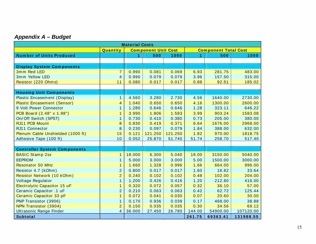
Appendix A – Budget Material Costs
Quantity Component Unit Cost Component Total Cost Number of Units Produced 1 500 1000 1 500 1000 Display System Components 3mm Red LED 7 0.990 0.081 0.069 6.93 281.75 483.00 3mm Yellow LED 4 0.990 0.079 0.079 3.96 157.50 315.00 Resistor (220 Ohms) 11 0.080 0.017 0.017 0.88 92.51 185.02 Housing Unit Components Plastic Encasement (Display) 1 4.560 3.280 2.730 4.56 1640.00 2730.00 Plastic Encasement (Sensor) 4 1.040 0.650 0.650 4.16 1300.00 2600.00 9 Volt Power Connector 1 1.280 0.646 0.646 1.28 323.11 646.22 PCB Board (2.48" x 1.98") 1 3.990 1.806 1.583 3.99 903.24 1583.08 On/Off Switch (SPST) 1 0.730 0.410 0.380 0.73 205.00 380.00 RJ11 PCB Mount 8 0.830 0.419 0.371 6.64 1676.00 2968.00 RJ11 Connector 8 0.230 0.097 0.079 1.84 388.00 632.00 Plenum Cable Unshielded (1000 ft) 15 0.121 121.250 121.250 1.82 970.00 1818.75 Adhesive Tape (100 ft) 10 0.052 25.870 51.740 51.74 258.70 517.40 Controller System Components BASIC Stamp 2sx 1 18.000 6.300 5.040 18.00 3150.00 5040.00 EEPROM 1 5.000 3.000 3.000 5.00 1500.00 3000.00 Resonator 50 MHz 1 1.660 1.328 0.996 1.66 664.00 996.00 Resistor 4.7 (kOhm) 2 0.800 0.017 0.017 1.60 16.82 33.64 Resistor Network (10 kOhm) 2 0.240 0.102 0.102 0.48 102.00 204.00 Voltage Regulator 1 1.200 0.426 0.416 1.20 212.80 416.00 Electrolytic Capacitor 15 uF 1 0.320 0.072 0.057 0.32 36.10 57.00 Ceramic Capacitor .1 uF 2 0.210 0.063 0.063 0.42 62.72 125.44 Ceramic Capacitor 33 pF 1 0.072 0.041 0.030 0.07 20.60 30.00 PNP Transistor (3906) 1 0.170 0.936 0.039 0.17 468.00 38.88 NPN Transistor (3904) 2 0.150 0.035 0.035 0.30 34.56 69.12 Ultrasonic Range Finder 4 36.000 27.450 26.780 144.00 54900.00 107120.00 Subtotal 261.75 69363.41 131988.55
16
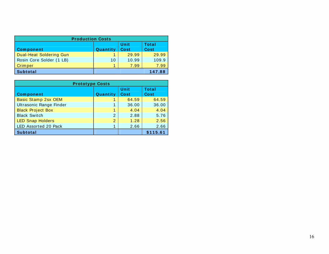
Production Costs
Component Quantity Unit Cost
Total Cost
Dual-Heat Soldering Gun 1 29.99 29.99 Rosin Core Solder (1 LB) 10 10.99 109.9 Crimper 1 7.99 7.99 Subtotal 147.88
Prototype Costs
Component Quantity Unit Cost
Total Cost
Basic Stamp 2sx OEM 1 64.59 64.59 Ultrasonic Range Finder 1 36.00 36.00 Black Project Box 1 4.04 4.04 Black Switch 2 2.88 5.76 LED Snap Holders 2 1.28 2.56 LED Assorted 20 Pack 1 2.66 2.66 Subtotal $115.61
17
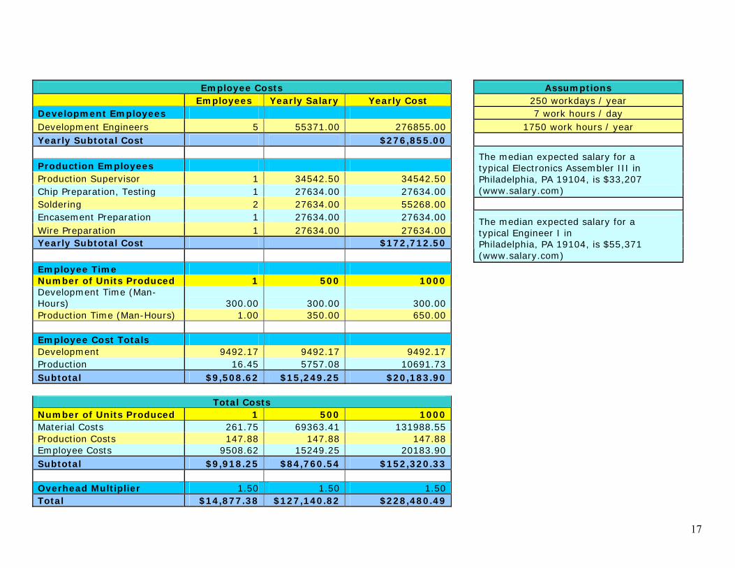
Employee Costs Assumptions
Employees Yearly Salary Yearly Cost 250 workdays / year Development Employees 7 work hours / day Development Engineers 5 55371.00 276855.00 1750 work hours / year Yearly Subtotal Cost $276,855.00 Production Employees Production Supervisor 1 34542.50 34542.50 Chip Preparation, Testing 1 27634.00 27634.00
The median expected salary for a typical Electronics Assembler III in Philadelphia, PA 19104, is $33,207 (www.salary.com)
Soldering 2 27634.00 55268.00 Encasement Preparation 1 27634.00 27634.00 Wire Preparation 1 27634.00 27634.00 Yearly Subtotal Cost $172,712.50
The median expected salary for a typical Engineer I in Philadelphia, PA 19104, is $55,371 (www.salary.com)
Employee Time Number of Units Produced 1 500 1000 Development Time (Man-Hours) 300.00 300.00 300.00 Production Time (Man-Hours) 1.00 350.00 650.00 Employee Cost Totals Development 9492.17 9492.17 9492.17 Production 16.45 5757.08 10691.73 Subtotal $9,508.62 $15,249.25 $20,183.90
Total Costs Number of Units Produced 1 500 1000 Material Costs 261.75 69363.41 131988.55 Production Costs 147.88 147.88 147.88 Employee Costs 9508.62 15249.25 20183.90 Subtotal $9,918.25 $84,760.54 $152,320.33 Overhead Multiplier 1.50 1.50 1.50 Total $14,877.38 $127,140.82 $228,480.49

18
Appendix B - Components Parallax (http://www.parallax.com) Product Name Parallax Stock # 1.) BASIC Stamp 2SX interpreter chip (SS) PBASIC2SX-28/SS 2.) 16K-byte EEPROM (Stamp 2SX Stamp 2P-DIP) 602-00013 3.) 50 MHz Resonator 250-05060 Acroname (http://www.acroname.com) Product Name Acroname Part # 4.) Devantech SRF04 R93-SRF04 Mouser (http://www.mouser.com) Product Name Mouser Part # 5.) Kobiconn Modular Jack PCB 4P-4C 154-UL6442 6.) Kobiconn Modular Plug 6P-4C 154-UL6234 7.) Eagle Plastic Devices Modular Crimping Tool 382-8100 8.) Serpac ABS Black Box 3.25"x4.38"x.91" 635-231-B Digi-Key (http://www.digikey.com) Product Name Digi-Key Part # 9.) General Cable Unshielded Plenum Cable C3105-1000-ND 10.) Keystone Electronics Plastic 9V Battery Holder 1294K-ND 11.) Lumex Inc. Red Diffused 3mm LED T1 Radial 67-1071-ND 12.) Lumex Inc. Yellow Diffused 3mm LED T1 Radial 67-1072-ND 13.) Fairchild Semiconductor IC Transistor NPN 3904 2N3904D26ZCT-ND 14.) Fairchild Semiconductor IC Transistor PNP 3906 2N3906D26ZCT-ND 15.) National Semiconductor IC 5V Voltage Regulator LM2940CS-5.0-ND 16.) BC Components Ceramic Capacitor 33pF 100V 1332PH-ND 17.) Kemet Ceramic Capacitor .1uF 100V 399-2150-ND 18.) BC Components Electrolytic Capacitor 15uF 63V 4067PHCT-ND 19.) Hammond Mfg. ABS Black Box 1.97"x1.38"x0.67" HM375-ND 20.) 3M Double Coated Vinyl Foam Tape 1/16" 1000ft. 3M44161B-ND 21.) Cherry Switch Black SPST Rocker Switch CH758-ND 22.) CTS Corporation Resistor Network 8 Pin 4 Res. 10KΩ 770-83-R10K-ND 23.) Panasonic 1/10W 5% 4.7KΩ Resistor P4.7KGCT-ND 24.) Panasonic 1/10W 5% 220Ω Resistor P220GCT-ND Express PCB (http://www.expresspcb.com) Product Name 25.) ExpressPCB 10 Day Production 2.5"x2.5"
19
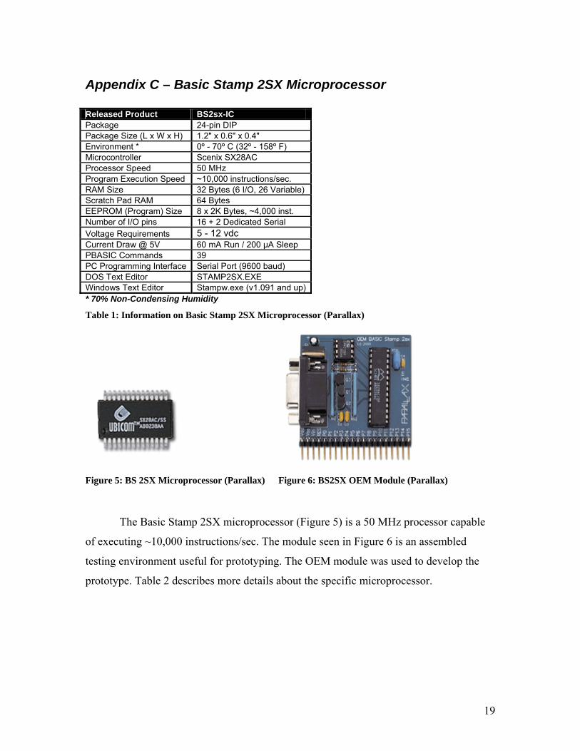
Appendix C – Basic Stamp 2SX Microprocessor Released Product BS2sx-IC Package 24-pin DIP Package Size (L x W x H) 1.2" x 0.6" x 0.4" Environment * 0º - 70º C (32º - 158º F) Microcontroller Scenix SX28AC Processor Speed 50 MHz Program Execution Speed ~10,000 instructions/sec. RAM Size 32 Bytes (6 I/O, 26 Variable) Scratch Pad RAM 64 Bytes EEPROM (Program) Size 8 x 2K Bytes, ~4,000 inst. Number of I/O pins 16 + 2 Dedicated Serial Voltage Requirements 5 - 12 vdc Current Draw @ 5V 60 mA Run / 200 µA Sleep PBASIC Commands 39 PC Programming Interface Serial Port (9600 baud) DOS Text Editor STAMP2SX.EXE Windows Text Editor Stampw.exe (v1.091 and up)* 70% Non-Condensing Humidity
Table 1: Information on Basic Stamp 2SX Microprocessor (Parallax)
Figure 5: BS 2SX Microprocessor (Parallax)
Figure 6: BS2SX OEM Module (Parallax)
The Basic Stamp 2SX microprocessor (Figure 5) is a 50 MHz processor capable
of executing ~10,000 instructions/sec. The module seen in Figure 6 is an assembled
testing environment useful for prototyping. The OEM module was used to develop the
prototype. Table 2 describes more details about the specific microprocessor.
20
Appendix D – Devantech SRF04 Ultrasonic Range Sensor
Figure 7: Timing diagram for the SRF04 (Robot Electronics)
Figure 8: Connections for the SRF04
(Robot Electronics)
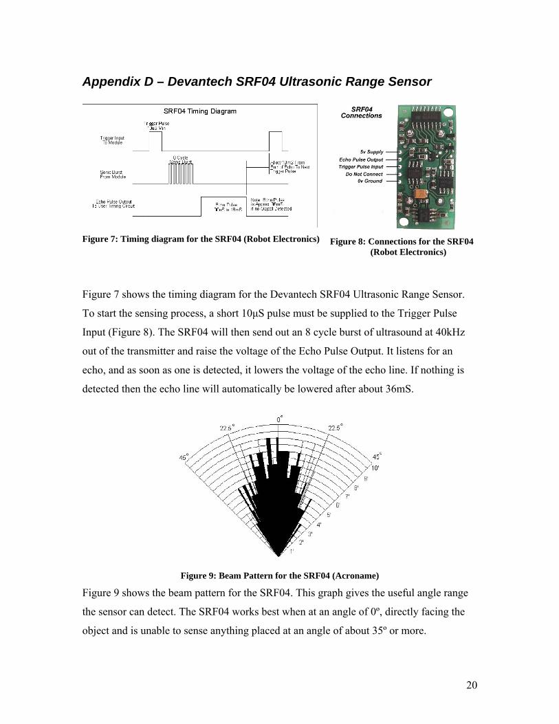
Figure 7 shows the timing diagram for the Devantech SRF04 Ultrasonic Range Sensor.
To start the sensing process, a short 10µS pulse must be supplied to the Trigger Pulse
Input (Figure 8). The SRF04 will then send out an 8 cycle burst of ultrasound at 40kHz
out of the transmitter and raise the voltage of the Echo Pulse Output. It listens for an
echo, and as soon as one is detected, it lowers the voltage of the echo line. If nothing is
detected then the echo line will automatically be lowered after about 36mS.
Figure 9: Beam Pattern for the SRF04 (Acroname)
Figure 9 shows the beam pattern for the SRF04. This graph gives the useful angle range
the sensor can detect. The SRF04 works best when at an angle of 0º, directly facing the
object and is unable to sense anything placed at an angle of about 35º or more.
21
Appendix E - BackAssist Prototype
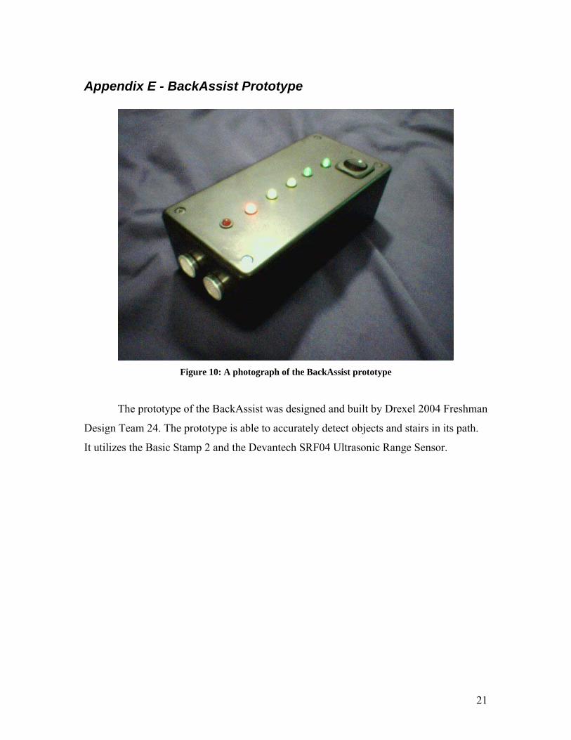
Figure 10: A photograph of the BackAssist prototype
The prototype of the BackAssist was designed and built by Drexel 2004 Freshman
Design Team 24. The prototype is able to accurately detect objects and stairs in its path.
It utilizes the Basic Stamp 2 and the Devantech SRF04 Ultrasonic Range Sensor.
22
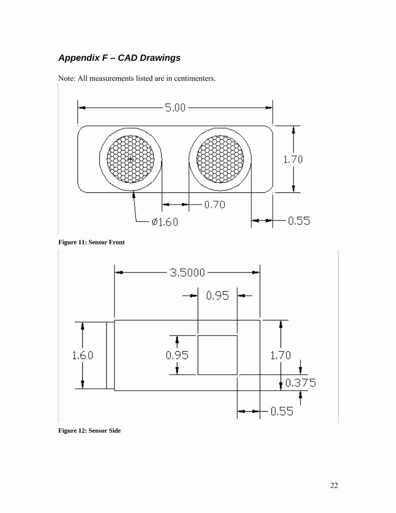
Appendix F – CAD Drawings Note: All measurements listed are in centimenters.
Figure 11: Sensor Front
Figure 12: Sensor Side
23
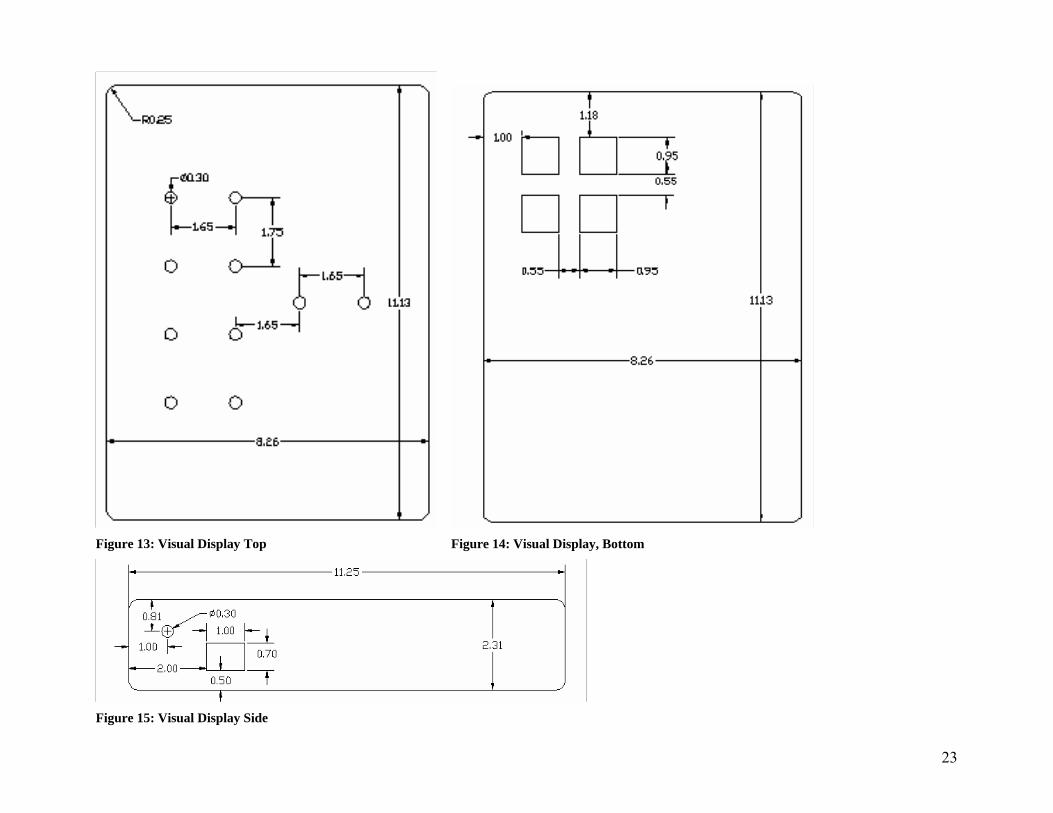
Figure 13: Visual Display Top Figure 14: Visual Display, Bottom
Figure 15: Visual Display Side
24
Appendix G – BackAssist Prototype Schematics
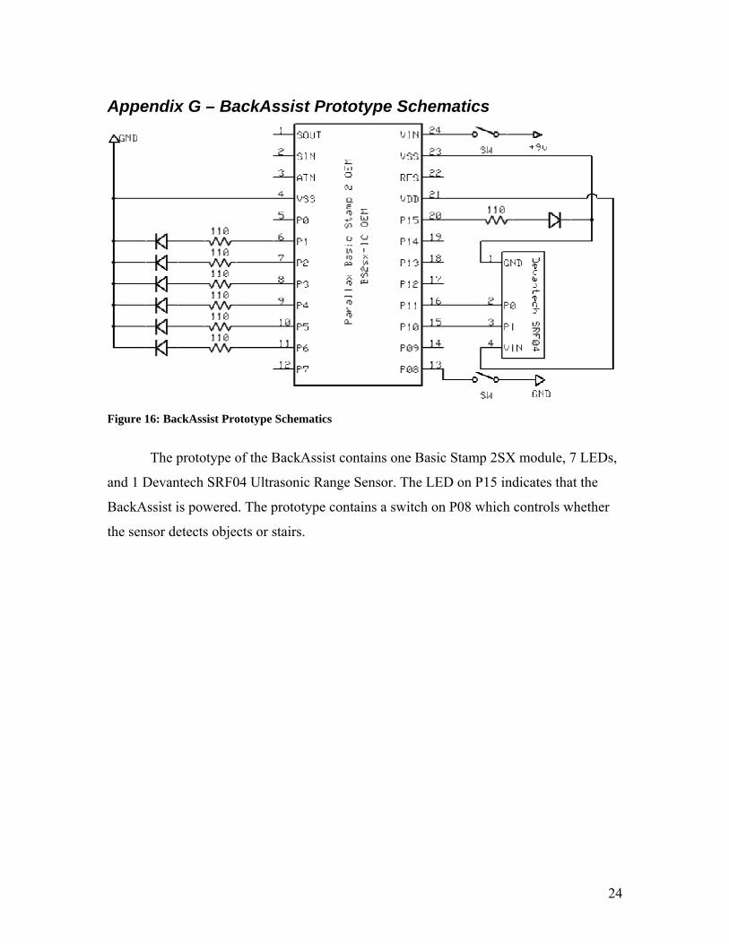
Figure 16: BackAssist Prototype Schematics
The prototype of the BackAssist contains one Basic Stamp 2SX module, 7 LEDs,
and 1 Devantech SRF04 Ultrasonic Range Sensor. The LED on P15 indicates that the
BackAssist is powered. The prototype contains a switch on P08 which controls whether
the sensor detects objects or stairs.
25
Appendix H – BackAssist Final Schematic
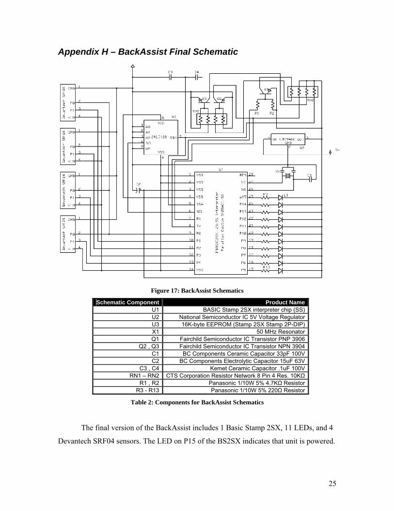
Figure 17: BackAssist Schematics
Schematic Component Product Name U1 BASIC Stamp 2SX interpreter chip (SS) U2 National Semiconductor IC 5V Voltage Regulator U3 16K-byte EEPROM (Stamp 2SX Stamp 2P-DIP) X1 50 MHz Resonator Q1 Fairchild Semiconductor IC Transistor PNP 3906
Q2 , Q3 Fairchild Semiconductor IC Transistor NPN 3904 C1 BC Components Ceramic Capacitor 33pF 100V C2 BC Components Electrolytic Capacitor 15uF 63V
C3 , C4 Kemet Ceramic Capacitor .1uF 100V RN1 – RN2 CTS Corporation Resistor Network 8 Pin 4 Res. 10KΩ
R1 , R2 Panasonic 1/10W 5% 4.7KΩ Resistor R3 - R13 Panasonic 1/10W 5% 220Ω Resistor
Table 2: Components for BackAssist Schematics
The final version of the BackAssist includes 1 Basic Stamp 2SX, 11 LEDs, and 4
Devantech SRF04 sensors. The LED on P15 of the BS2SX indicates that unit is powered.
26
Appendix I – BackAssist Flow Charts
Detecting Objects
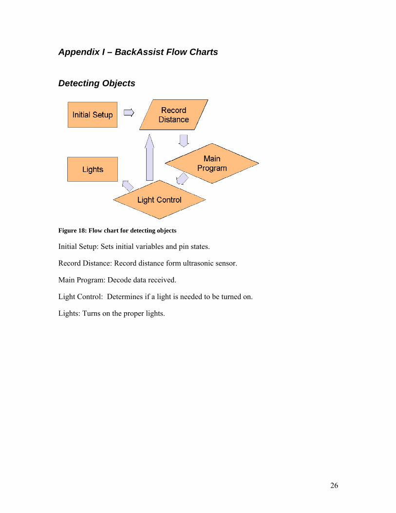
Figure 18: Flow chart for detecting objects
Initial Setup: Sets initial variables and pin states.
Record Distance: Record distance form ultrasonic sensor.
Main Program: Decode data received.
Light Control: Determines if a light is needed to be turned on.
Lights: Turns on the proper lights.
27
Detecting Stairs
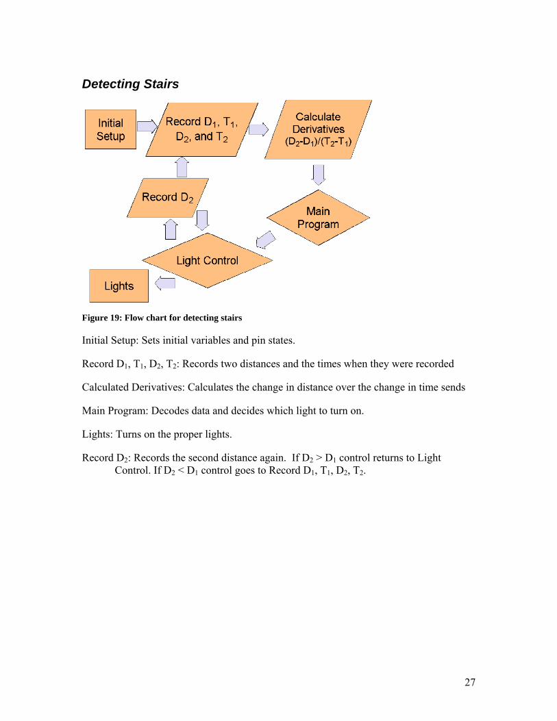
Figure 19: Flow chart for detecting stairs
Initial Setup: Sets initial variables and pin states.
Record D1, T1, D2, T2: Records two distances and the times when they were recorded
Calculated Derivatives: Calculates the change in distance over the change in time sends
Main Program: Decodes data and decides which light to turn on.
Lights: Turns on the proper lights.
Record D2: Records the second distance again. If D2 > D1 control returns to Light Control. If D2 < D1 control goes to Record D1, T1, D2, T2.
28
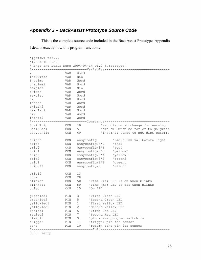
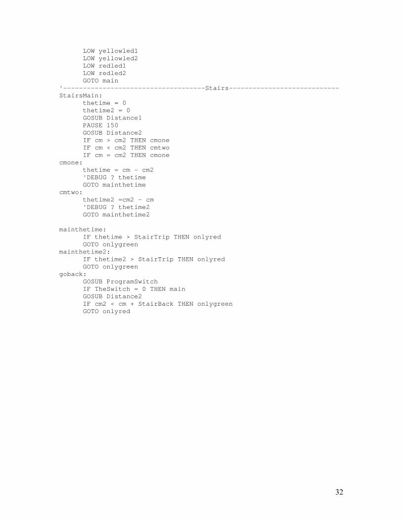
Appendix J – BackAssist Prototype Source Code
This is the complete source code included in the BackAssist Prototype. Appendix
I details exactly how this program functions.
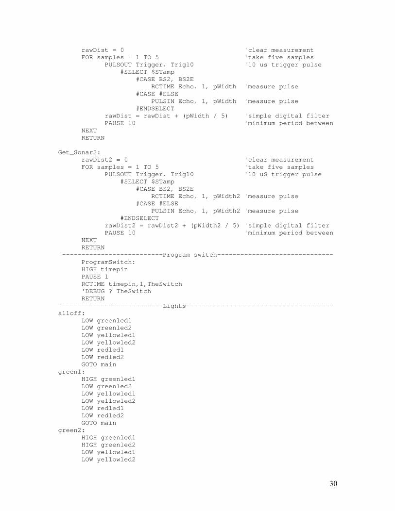
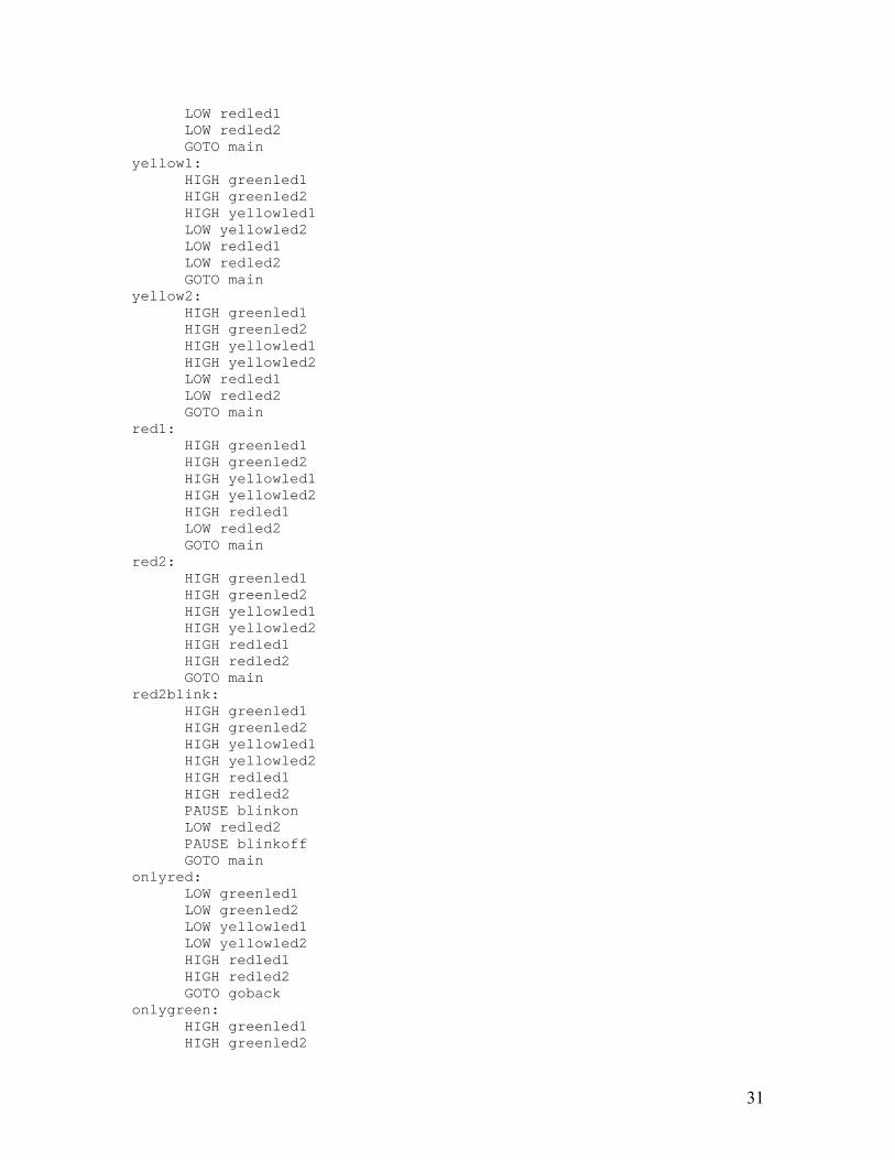
'$STAMP BS2sx '$PBASIC 2.5 'Range and Stair Demo 2004-04-14 v1.0 [Prototype] '----------------------------Variables--------------------------------- x VAR Word TheSwitch VAR Nib Thetime VAR Word thetime2 VAR Word samples VAR Nib pwidth VAR Word rawdist VAR Word cm VAR Word inches VAR Word pwidth2 VAR Word rawdist2 VAR Word cm2 VAR Word inches2 VAR Word '----------------------------Constants--------------------------------- StairTrip CON 10 'amt dist must change for warning StairBack CON 5 'amt cm2 must be for cm to go green easyconfig CON 60 'internal const to set dist cutoffs trip6b CON easyconfig 'red2blink val before light trip6 CON easyconfig/8*7 'red2 trip5 CON easyconfig/8*6 'red1 trip4 CON easyconfig/8*5 'yellow2 trip3 CON easyconfig/8*4 'yellow1 trip2 CON easyconfig/8*3 'green2 trip1 CON easyconfig/8*2 'green1 tripoff CON easyconfig/8 'alloff trig10 CON 13 tocm CON 78 blinkon CON 50 'Time (ms) LED is on when blinks blinkoff CON 50 'Time (ms) LED is off when blinks onled CON 15 'On LED greenled1 PIN 3 'First Green LED greenled2 PIN 5 'Second Green LED yellowled1 PIN 1 'First Yellow LED yellowled2 PIN 2 'Second Yellow LED redled1 PIN 6 'First Red LED redled2 PIN 7 'Second Red LED timepin PIN 9 'pin where program switch is trigger PIN 11 'trigger pin for sensor echo PIN 10 'return echo pin for sensor '-------------------------------Init----------------------------------- GOSUB setup
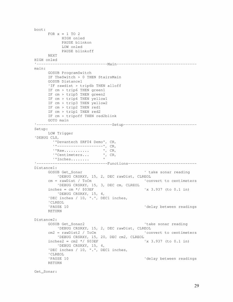
29
boot: FOR x = 1 TO 2
HIGH onled PAUSE blinkon LOW onled PAUSE blinkoff
NEXT HIGH onled '-------------------------------Main----------------------------------- main:
GOSUB ProgramSwitch IF TheSwitch > 0 THEN StairsMain GOSUB Distance1 'IF rawdist > trip6b THEN alloff IF cm > trip6 THEN green1 IF cm > trip5 THEN green2 IF cm > trip4 THEN yellow1 IF cm > trip3 THEN yellow2 IF cm > trip2 THEN red1 IF cm > trip1 THEN red2 IF cm > tripoff THEN red2blink GOTO main
'---------------------------------Setup-------------------------------- Setup: LOW Trigger 'DEBUG CLS, '"Devantech SRF04 Demo", CR, '"--------------------", CR, '"Raw........... ", CR, '"Centimeters... ", CR, '"Inches........ " '-------------------------------Functions------------------------------ Distance1:
GOSUB Get_Sonar ' take sonar reading 'DEBUG CRSRXY, 15, 2, DEC rawDist, CLREOL cm = rawDist / ToCm 'convert to centimeters 'DEBUG CRSRXY, 15, 3, DEC cm, CLREOL inches = cm */ $03EF 'x 3.937 (to 0.1 in) 'DEBUG CRSRXY, 15, 4, 'DEC inches / 10, ".", DEC1 inches, 'CLREOL 'PAUSE 10 'delay between readings RETURN
Distance2:
GOSUB Get_Sonar2 'take sonar reading 'DEBUG CRSRXY, 15, 2, DEC rawDist, CLREOL cm2 = rawDist2 / ToCm 'convert to centimeters 'DEBUG CRSRXY, 15, 20, DEC cm2, CLREOL inches2 = cm2 */ $03EF 'x 3.937 (to 0.1 in) 'DEBUG CRSRXY, 15, 4, 'DEC inches / 10, ".", DEC1 inches, 'CLREOL 'PAUSE 10 'delay between readings RETURN
Get_Sonar:
30
rawDist = 0 'clear measurement FOR samples = 1 TO 5 'take five samples
PULSOUT Trigger, Trig10 '10 us trigger pulse #SELECT $STamp #CASE BS2, BS2E RCTIME Echo, 1, pWidth 'measure pulse #CASE #ELSE PULSIN Echo, 1, pWidth 'measure pulse #ENDSELECT rawDist = rawDist + (pWidth / 5) 'simple digital filter PAUSE 10 'minimum period between
NEXT RETURN
Get_Sonar2:
rawDist2 = 0 'clear measurement FOR samples = 1 TO 5 'take five samples
PULSOUT Trigger, Trig10 '10 uS trigger pulse #SELECT $STamp #CASE BS2, BS2E RCTIME Echo, 1, pWidth2 'measure pulse #CASE #ELSE PULSIN Echo, 1, pWidth2 'measure pulse #ENDSELECT rawDist2 = rawDist2 + (pWidth2 / 5) 'simple digital filter PAUSE 10 'minimum period between
NEXT RETURN
'--------------------------Program switch------------------------------ ProgramSwitch: HIGH timepin PAUSE 1 RCTIME timepin,1,TheSwitch 'DEBUG ? TheSwitch RETURN
'--------------------------Lights-------------------------------------- alloff:
LOW greenled1 LOW greenled2 LOW yellowled1 LOW yellowled2 LOW redled1 LOW redled2 GOTO main
green1: HIGH greenled1 LOW greenled2 LOW yellowled1 LOW yellowled2 LOW redled1 LOW redled2 GOTO main
green2: HIGH greenled1 HIGH greenled2 LOW yellowled1 LOW yellowled2
31
LOW redled1 LOW redled2 GOTO main
yellow1: HIGH greenled1 HIGH greenled2 HIGH yellowled1 LOW yellowled2 LOW redled1 LOW redled2 GOTO main
yellow2: HIGH greenled1 HIGH greenled2 HIGH yellowled1 HIGH yellowled2 LOW redled1 LOW redled2 GOTO main
red1: HIGH greenled1 HIGH greenled2 HIGH yellowled1 HIGH yellowled2 HIGH redled1 LOW redled2 GOTO main
red2: HIGH greenled1 HIGH greenled2 HIGH yellowled1 HIGH yellowled2 HIGH redled1 HIGH redled2 GOTO main
red2blink: HIGH greenled1 HIGH greenled2 HIGH yellowled1 HIGH yellowled2 HIGH redled1 HIGH redled2 PAUSE blinkon LOW redled2 PAUSE blinkoff GOTO main
onlyred: LOW greenled1 LOW greenled2 LOW yellowled1 LOW yellowled2 HIGH redled1 HIGH redled2 GOTO goback
onlygreen: HIGH greenled1 HIGH greenled2
32
LOW yellowled1 LOW yellowled2 LOW redled1 LOW redled2 GOTO main
'------------------------------------Stairs---------------------------- StairsMain:
thetime = 0 thetime2 = 0 GOSUB Distance1 PAUSE 150 GOSUB Distance2 IF cm > cm2 THEN cmone IF cm < cm2 THEN cmtwo IF cm = cm2 THEN cmone
cmone: thetime = cm - cm2 'DEBUG ? thetime GOTO mainthetime
cmtwo: thetime2 =cm2 - cm 'DEBUG ? thetime2 GOTO mainthetime2
mainthetime:
IF thetime > StairTrip THEN onlyred GOTO onlygreen
mainthetime2: IF thetime2 > StairTrip THEN onlyred GOTO onlygreen
goback: GOSUB ProgramSwitch IF TheSwitch = 0 THEN main GOSUB Distance2 IF cm2 < cm + StairBack THEN onlygreen GOTO onlyred

33
Appendix L – Qualifications
Each member of Team 24 brings useful skills to the team. Isabelle Harroch is
talented in obtaining useful research. Daniel M. Lofaro is familiar with the electronic
circuits and microprocessors that are used in the BackAssist. Kevin Lynch is adept at
presenting technical data in both written and visual ways. Alexander Silverman is
talented at finalizing and presenting solutions as well as testing designs. Stephanie Toth
has good organizational and secretarial skills.
34
Isabelle Harroch [email protected] ———————————————————————————————————— Honors and Awads
Scientific French-Based Baccalaureate(total point above average) AJ Drexel Scholar, 2003-present
Education Drexel University, Philadelphia, PA Bachelor of science in Biomedical engineering, Graduation-June 2007 Cumultive GPA: N/A Relevant coursework
Physics Fundamentals of engineering I,II Mathematics Fundamentals of Engineering I,II Chemistry, Biology Fundamentals of Engineering I,II Engineering Design Lab I,II Freshman Design Project: Participated as part of a design team
Computer Skills
Hardware: IBM, Mcintosh computers, Gateway and Dell laptops Operating System: Microsoft 2000 professional, Windows Software: Microsoft Word 2000, Microsoft Excel, Maple, Autocad,labview,Internet Explorer,ICQ, MSN, Adobe Photoshop,Adobe Illustrator, Quart Express
Language Skills
Fluent in French(native language) French educated until high school graduation(June 2003) Studies in the English language:september 2003-present(Drexel University)
Experimentation Skills
Relevant courses in Biology: Genetic course(ENH high school,September-December,2002,Morocco) Geology course(ENH high school,January-March,2003) Immune system course(ENH high school,April-June,2003) Participated to a team project concerning nutrition and alimentation Biology experimentation lab and Biology computer lab(ENH,September-December,2002)
Job Experience Val D'Anfa Clinic,Inc, Casablanca, Morocco Nursery assistant in the emergencies, June to August,2001
• Attended meeting aimed to coordinate multiple emergencies be ,to learned how to be well-organised and efficient. • took care of ill children and organised recreation programs • received clients'phone calls and created new folders • participated to the nursery duties(brough meals,medications,...to the patients • attended surgeries and consultations
35
Daniel M Lofaro [email protected]
Kelly Hall 303B 1163 Norsam Rd 203 N 34th St Gladwyne, PA 19035 Philadelphia, PA 19104 610-519-0992 610-505-4445 ——————————————————————————————————————— Education Drexel University, Philadelphia, PA Bachelor of Science in Engineering, Anticipated Graduation - June 2008 Electrical and Computer Engineering, GPA (3.38) Relevant Coursework Introduction to The Art of Engineering Part I, II & III
Math Foundations of Engineering Part I, II & III Physics Foundations of Engineering Part I, II & III Humanities for Engineers Part I, II & III Chemistry/Biology Foundations of Engineering Part I, II & III Introduction to Electrical and Computer Engineering (Temple University)
Computer Experience • Hardware: PC, Mac Networks: LAN, WLAN, TCP/IP • Operating System: Windows XP/2000/NT/9x, Mac OS 10.x/9.x/8.6, Unix (GenToo) • Software: AutoCAD 200x, Microsoft Word/ Excel/ PowerPoint/ Project, LabView6.1, Maple9 • Languages: Java, PBasic, HTML
Work Experience Drexel University, Philadelphia, PA Team Captain, October 2003 to May 2004
• Topic: Assistance for wheelchair bound individuals with the process of safely moving in reverse • Work: All steps of the design process. Working prototype of design made by Daniel M. Lofaro • Recognition: Only team to have project presentation showcased by Drexel
Drexel University, Philadelphia, PA K'NEX Vehicle Competition, September 2003
• Purpose: Build self propelled vehicle out of KNEX that can to various tasks • Overall Ranking: 1st place out of over 120 teams
FIRST Robotics, Drexel University Philadelphia, PA Volunteer, March 2004 • Setup and dismantle the playing field • Reset all playable objects after each match
•Maintain field, fix damages
Cabrini College, Radnor, PA Assistant Technical Serviceman, March to July 2003
• Load new PC's with OS, Load new Macs with OS • Re-image old Macs for donation, Dismantle old work stations, Assemble new work stations
Self Employed, Gladwyne, PA 19035 Computer Repair , August 2001 to Present
• Data Recovery, Install Microsoft OS, Windows Recovery, Virus Removal, Hardware Install, Computer Setup, Computer Buyer (For Clients), Technical Support (Phone and At Home), Hardware and Software Tutorial ,Application Setup
Leadership • Band President 2001-03 • Orchestra President 2001-03 • Pep-Band President 2001-03 • Science Olympiad Event Captain 2001-03 • Drexel Freshman Design Project Team Captain
Honors and Awards • Eight gold Science Olympiad metals • Six silver Science Olympiad metals • Nine bronze Science Olympiad metals • Forth in the nation, Science Olympiad 2002-03 • Second in the nation, Science Olympiad 2001-02
Specialties • IEEE member • Experience with Microcontrollers (BS, BS2) • Experienced in soldering • Intermediate electrical circuits • Intermediate AI development • Experienced with DMM and Oscilloscope • Design and build autonomous and RC robots
36
Kevin M Lynch 3301 Race St
Philadelphia, PA 19104 215-571-4542
[email protected] ———————————————————————————————————— Education Drexel University Philadelphia, PA Bachelor of Science in Computer Engineering Anticipated Graduation: June 2008 Cumulative GPA: 4.00 Coursework
Mathematical Foundations of Engineering I, II, III Physical Foundations of Engineering I, II, III Engineering Design Lab I, II, III (Circuits, Instruments, Computers) Fundamentals of Intelligent Systems Fundamentals of Electric Circuits
Skills
Operating Systems: Windows 98/2000/XP, GNU/Linux, MacOS X Software: Microsoft Office 2000/XP (Word, Excel, Access, Powerpoint), National Instruments LabView 6.1, Adobe Photoshop 7.0, Adobe PageMaker 7.0, Autodesk AutoCad 2004, Visual Studio 6 Languages: Java, Perl, PHP, HTML, Visual Basic
Engineering Design Project
Designed and created a sensor system to detect objects behind wheelchairs and warn the operator Presented the design to Drexel professors and industry leaders
Experience Drexel University Philadelphia, PA Undergraduate Research Assistant (to be working Summer 2004)June 2004 to September 2004
Will learn to use Cisco routers and network protocols Will research and experiment with methods to better balance network traffic loads
Red Lobster Delran, NJ Dining Room Attendant March 2002 to September 2002
Maintained an efficient and pleasurable dining atmosphere Trained others to clean and set tables and clean the dining area Assisted customers with concerns and requests
Honors and Awards Member of the Pennoni Honors College, 2003 - Present Riverside High School Valedictorian, 2003
37
Alexander J Silverman 1195 Williams Dr
Shrub Oak, NY 10588 914-528-9138
[email protected] Education Drexel University Philadelphia, PA Bachelor of Engineering Anticipated Graduation - June 2008 Mechanical Engineering Cumulative GPA: 3.4 Honors and Awards
• Rensselaer Polytechnic Institute of Technology Medal • Drexel University Dean’s Scholarship
Skills
Operating Systems: Mac OS 9, X; Microsoft Windows 98, XP Software: AutoCAD, Maple, LABview, Microsoft Word, Excel, PowerPoint Hardware: Apple Macintosh Automotive: Engine tune up and maintenance
Relevant Coursework
Physics I, II, III Calculus I, II, III Chemistry I, II Biology Humanities for Engineering Art of Engineering Computer Laboratories Instruments Laboratories Freshman Design Project: Proximity sensors for wheelchairs
Organizations
The American Society of Mechanical Engineers The Society of Automotive Engineers
Experience Vail Buick, Pontiac, and GMC Truck Bedford Hills, NY Automotive Detailer June 2003 to Present
• Detailed all new and used vehicles before their presentation for marketing to customers. • Shuttled cars between buildings in safe manner to expedite sales. • Assisted with preparation of vehicles sold according to state and federal regulations.
Our Montessori School Yorktown, NY Extended Day Staff September 1999 to Present
• Monitored children to ensure their safety in after school program. • Planned activities to enhance social and educational development. • Spoke to parents to provide feedback on students' progress. • Marketed services and answered inquiries about the school and programs offered.
The Auto Center Chappaqua, NY Shop Helper June to September 2001; June to September 2002
• Performed oil changes, tire changes and balancing, and helped with more in depth automotive services. • Maintained shop in orderly fashion to allow technicians to perform their jobs more efficiently.
38
Stephanie A Toth 1827 W Cedar St
Allentown, PA 18104-4127 610-432-9479
[email protected] ———————————————————————————————————————————————— Education
Drexel University Philadelphia, PA Bachelor of Science, Chemical Engineering Anticipated Graduation - June 2008 Cumulative GPA: 3.66
Honors and Awards
Drexel Scholarship, 2003 National Society of Collegiate Scholars, 2003 William Allen Athletic Booster Club Scholarship, 2003 Women's Society of Engineers Award, 2003 Captain of High School Diving team, 2003-2004 Captain of High School Softball team, 2003-2004
Relevant Coursework The Art of Engineering and Design Calculus I, II, III Chemistry I, II Physics I, II, III Biology I
Fresheman Engineering Design Project • Participated as part of an engineering design team that developed plans to assist people with disabililties • Took position as Secretary of the design team • Researched data, anaylized findings, presented results to faculty and peers • Worked together to develop proposals, reports, and a prototype for the presentation • Met weekly with team to provide status updates and develop deadlines
Computer Skills Hardware: Dell Software: Microsoft Word, Excel, Powerpoint, Internet Explorer, Maple, Auto Cad, Lab View, and Java Operating Systems: Windows 98/2000/XP
Work Experience Bedway's Fresh Fruits Allentown, PA Clerk June, 2000 to May 2003
• Oversaw produce department • Set up displays of merchandise • Closed Store
Vector Whitehall, PA Cutco Sales Representative June, 2003 to Present
• Marketed merchandise to consumers • Conducted weekly meetings to encourage other representatives • Participated in conferences, conference calls, advertising, and monthly competitions for the company
Volunteering Experience Paul L. Dunbar School Philadelphia, PA Mentor January to February, 2004
• Participated in program with the Philadelphia Cares Center • Tutored fifth and sixth graders in Science and Math
Activities • Society of Women Engineers CEO Chairman, 2003 to Present • American Institute of Chemical Engineering; Student Chapter