Embed Size (px)
Citation preview
8/10/2019 Fresnel Zone Consideration During LOS Survey
http://slidepdf.com/reader/full/fresnel-zone-consideration-during-los-survey 1/6
Case Study
Fresnel Zone consideration during LOS survey
Shaharuddin Bin Abdul Karim (S00708396)
Introduction
Over the time, an engineer may only consider a clear line of sight during site survey or LOS
survey to determine a reliable digital microwave transmission. However a question may arise,
is it sufficiently enough to rely much on it?
This article, which meant for engineers who do the LOS survey and it provides another
consideration apart from a clear line of sight.
Fresnel Zone and their effect
Direct wave, which obviously travel in straight line from say, Site A to Site B, is unaffected of
any obstruction if the LOS survey was successfully done. However, it is a rule of thumb to
know that the transmission is not just travel in a virtually straight line, it is also travel via a
bended or deflected curve which due to the obstruction in between the sites. This factor is
caused by multipath propagations and usually the phenomenon of this propagation is regarded
as diffractions, reflections etc
In Fresnel zone theory, there is a series of virtual elliptical shape zone exist between one
transmission end to another. These zones provide a reference for the surveyor to predict the
potential kind of losses for further consideration.
In addition to the zone, these series of zone are regarded with connotations which will be used
further in this article; the smallest zone which converges along the direct wave is called
Fresnel Zone 1 (F1). As the zone increases its radius to a certain extend, it is regarded as F2,
F3, F4 and so on. The Receive Signal Level (RSL) on the other hand, will decrease as the
Fresnel Zone number is increased. Due to its phase differences, the odd number of Fresnel
Zone is associated with the amplification the signal while the even number of it will attenuate it.
At the far end side, it will receive the signals coming from all of these zones via vector sum. In
other words, the final signal is a vector composition of direct wanted signal and reflected
unwanted signals from various layers of the Fresnel Zones. Consequently, one could
experience a fluctuating RSL over a period of time. Therefore, the focus during the LOS survey
is to reduce this significant level of fluctuation which occasionally may lead to drop in
transmission.
1/6
8/10/2019 Fresnel Zone Consideration During LOS Survey
http://slidepdf.com/reader/full/fresnel-zone-consideration-during-los-survey 2/6
Case Study
How to determine Fresnel Zone?
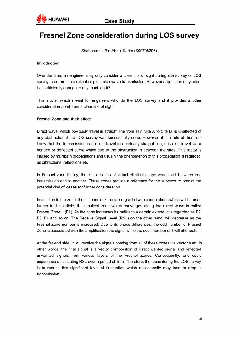
As the understanding of the Fresnel zone blooming, one would understanding that the zone is
actually an invisible curvatures, where the only way to detect the curvature in by the mean of
clearance. Clearance is the different in length between an obstruction to the Fresnel zone’s
curve. It is suggested that an obstruction must not be closer to 60% of the curve radius. In the
other word, at any point of the path between Site A and Site B, an obstruction would only be
acceptable during LOS survey if it would stand clear 60% off the direct wave between the
transmission sites. (see Figure 1)
Figure 1: Clearance (c1) relationship with the Fresnel Zone Radius (r1),
1*6.01 r c ≤
Furthermore, this article provides an excel sheet which act as a calculator to determine the
clearance at any point of the transmission path and at any Fresnel Zone number. Please refer
to the Appendix A for the calculator. (Appendix A - Fresnel Radius calculator.xls)
In this excel spreadsheet, one could enter the Fresnel Zone number, the operating frequency,
the path length between the Site A and Site B, and the obstruction location with respect to the
left-most position (referred as d1 in Figure 1).
Notice that the clearance off the direct wave is rather small on any case of the microwave
transmission parameters such as frequency, path length and obstruction location from TX (or
RX). Therefore, a clear line of sight, without any slight obstruction is expected during the line of
sight findings. Otherwise, another type of loss would come into the equation which is
Knife-Edge diffraction loss, which unfortunately is not covered in this article.
2/6
8/10/2019 Fresnel Zone Consideration During LOS Survey
http://slidepdf.com/reader/full/fresnel-zone-consideration-during-los-survey 3/6
Case Study
Fresnel Zone realization using Pathloss 4.0
One should complete a link between Site A to Site B by using Pathloss 4.0 software. The
essential information that need to be included prior of the Fresnel calculation are, a high
resolution digital map (SRTM or UTM) to define the terrain plain between the two points and a
defined antenna heights which provide a clear line of sight.
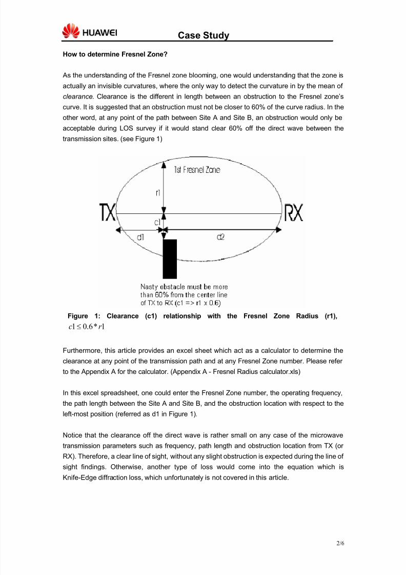
After the information has been keyed into Pathloss 4.0, press Ctrl+R or Module>>Diffraction to
go to Diffraction page. This page contains the terrain profile between the transmission sites
(refer to Figure 2)
Figure 2: Diffraction page in Pathloss 4.0
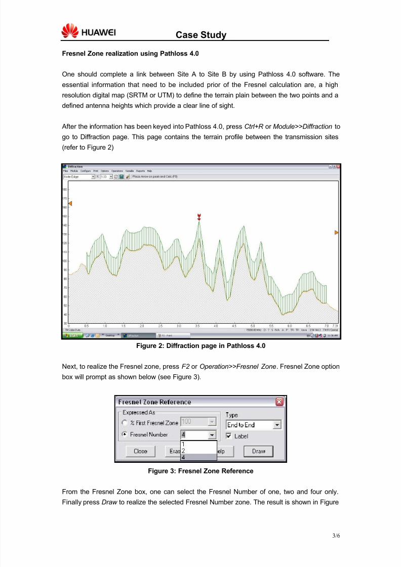
Next, to realize the Fresnel zone, press F2 or Operation>>Fresnel Zone. Fresnel Zone option
box will prompt as shown below (see Figure 3).
Figure 3: Fresnel Zone Reference
From the Fresnel Zone box, one can select the Fresnel Number of one, two and four only.
Finally press Draw to realize the selected Fresnel Number zone. The result is shown in Figure
3/6
8/10/2019 Fresnel Zone Consideration During LOS Survey
http://slidepdf.com/reader/full/fresnel-zone-consideration-during-los-survey 4/6
Case Study
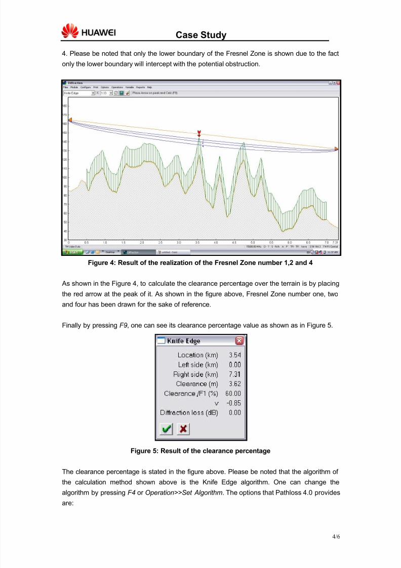
4. Please be noted that only the lower boundary of the Fresnel Zone is shown due to the fact
only the lower boundary will intercept with the potential obstruction.
Figure 4: Result of the realization of the Fresnel Zone number 1,2 and 4
As shown in the Figure 4, to calculate the clearance percentage over the terrain is by placing
the red arrow at the peak of it. As shown in the figure above, Fresnel Zone number one, two
and four has been drawn for the sake of reference.
Finally by pressing F9, one can see its clearance percentage value as shown as in Figure 5.
Figure 5: Result of the clearance percentage
The clearance percentage is stated in the figure above. Please be noted that the algorithm of
the calculation method shown above is the Knife Edge algorithm. One can change the
algorithm by pressing F4 or Operation>>Set Algorithm. The options that Pathloss 4.0 provides
are:
4/6
8/10/2019 Fresnel Zone Consideration During LOS Survey
http://slidepdf.com/reader/full/fresnel-zone-consideration-during-los-survey 5/6
Case Study
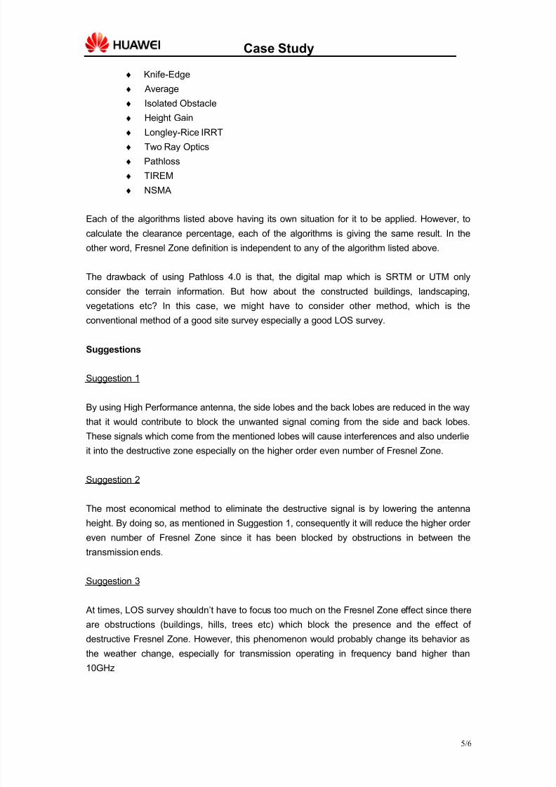
♦ Knife-Edge
♦ Average
♦ Isolated Obstacle
♦ Height Gain
♦ Longley-Rice IRRT
♦ Two Ray Optics
♦ Pathloss
♦ TIREM
♦ NSMA
Each of the algorithms listed above having its own situation for it to be applied. However, to
calculate the clearance percentage, each of the algorithms is giving the same result. In the
other word, Fresnel Zone definition is independent to any of the algorithm listed above.
The drawback of using Pathloss 4.0 is that, the digital map which is SRTM or UTM only
consider the terrain information. But how about the constructed buildings, landscaping,
vegetations etc? In this case, we might have to consider other method, which is the
conventional method of a good site survey especially a good LOS survey.
Suggestions
Suggestion 1
By using High Performance antenna, the side lobes and the back lobes are reduced in the way
that it would contribute to block the unwanted signal coming from the side and back lobes.
These signals which come from the mentioned lobes will cause interferences and also underlie
it into the destructive zone especially on the higher order even number of Fresnel Zone.
Suggestion 2
The most economical method to eliminate the destructive signal is by lowering the antenna
height. By doing so, as mentioned in Suggestion 1, consequently it will reduce the higher order
even number of Fresnel Zone since it has been blocked by obstructions in between the
transmission ends.
Suggestion 3
At times, LOS survey shouldn’t have to focus too much on the Fresnel Zone effect since there
are obstructions (buildings, hills, trees etc) which block the presence and the effect of
destructive Fresnel Zone. However, this phenomenon would probably change its behavior as
the weather change, especially for transmission operating in frequency band higher than
10GHz
5/6
8/10/2019 Fresnel Zone Consideration During LOS Survey
http://slidepdf.com/reader/full/fresnel-zone-consideration-during-los-survey 6/6
Case Study
Conclusion
Despite of the proposals suggested throughout this article, the only practical way so far is
having a rather successful LOS survey. A surveyor must be sensitive enough to notice any of
the potential development such as construction as well as vegetation growth along the path
towards the far end. Otherwise, the link would solely rely merely on the cushioned of Fade
Margin and its Annual Availability. Though it is considered a reliable solution, yet it is still not
good enough to cater the effect the Fresnel Zone as explained in this article.
References
1. “http://www.zytrax.com/tech/wireless/fresnel.htm”, contains ideas and effects of Fresnel
Zone
2. “http://en.wikipedia.org/wiki/Fresnel_zone”, contains ideas, effects of Fresnel Zone and
Clearance
3. “www.pathloss.com/forums”, contains methods to reduce Fresnel Zone effect
4. Digital Microwave Communication Principle Slideshow, Huawei Support Website
5. “The elliptical Fresnel-zone Plate antenna”, van Houten, J.M.; Herben, M.H.A.J, IEEE
journal
6/6