Embed Size (px)
Citation preview
FUJITSU SEMICONDUCTOR
app.book 1 ページ 2001年11月13日 火曜日 午後8時44分
CONTROLLER MANUAL
FR/F2MCFAMILY
SOFTUNE LINKAGE KIT MANUALfor V3

FR/F2MC FAMILY
SOFTUNE LINKAGE KIT MANUALfor V3
FUJITSU LIMITED


i
PREFACE
� Objectives and Intended Readership
This manual describes the functions and operations of the Fujitsu Softune Linkage Kit operating on Windows 95/98/Me,Windows NT and Windows 2000.
This manual is intended for engineers who are developing application programs using the FR family/F2MC-16 family/F2MC-8L family microcontroller.
The linkage kit consists of three kinds of program: linker, librarian and converter.
� Trademarks
Microsoft, MS-DOS, and Windows are registered trademarks of Microsoft Corporation in the U.S.A. and other countries.

ii
� Configuration of this manual
This manual consists of the following two parts:
PART 1 LINKAGE KIT
Explains an outline of the tools included in linkage kit and the common items that apply to all tools.
PART 2 LINKER
Explains the specifications, options, and output lists of a linker.
PART 3 LIBRARIAN
Explains the specifications, options, and output lists of a librarian.
PART 4 OBJECT FORMAT CONVERTERS
Explains the specifications,options,and output lists of a object format converters.
Appendices
Explains the error messages of the linkage kit, Intel HEX, Intel extended HEX format, and Motorola S record format.
iii
2001 FUJITSU LIMITED Printed in Japan
• The contents of this document are subject to change without notice. Customers are advised to consultwith FUJITSU sales representatives before ordering.
• The information and circuit diagrams in this document are presented as examples of semiconductordevice applications, and are not intended to be incorporated in devices for actual use. Also, FUJITSU isunable to assume responsibility for infringement of any patent rights or other rights of third partiesarising from the use of this information or circuit diagrams.
• The products described in this document are designed, developed and manufactured as contemplatedfor general use, including without limitation, ordinary industrial use, general office use, personal use, andhousehold use, but are not designed, developed and manufactured as contemplated (1) for useaccompanying fatal risks or dangers that, unless extremely high safety is secured, could have a seriouseffect to the public, and could lead directly to death, personal injury, severe physical damage or otherloss (i.e., nuclear reaction control in nuclear facility, aircraft flight control, air traffic control, masstransport control, medical life support system, missile launch control in weapon system), or (2) for userequiring extremely high reliability (i.e., submersible repeater and artificial satellite). Please note that Fujitsu will not be liable against you and/or any third party for any claims or damagesarising in connection with above-mentioned uses of the products.
• Any semiconductor devices have an inherent chance of failure. You must protect against injury, damageor loss from such failures by incorporating safety design measures into your facility and equipment suchas redundancy, fire protection, and prevention of over-current levels and other abnormal operatingconditions.
• If any products described in this document represent goods or technologies subject to certainrestrictions on export under the Foreign Exchange and Foreign Trade Law of Japan, the priorauthorization by Japanese government will be required for export of those products from Japan.
iv
READING THIS MANUAL
� Product name abbreviation
In this manual, product names are abbreviated as follows:
Microsoft® Windows® 95 operating system, Microsoft® Windows® 98 operating system andMicrosoft® Windows® Millennium Edition operating system are abbreviated Windows 95/98/Me.
Microsoft® Windows NT® Server network operating system Version 4.0 and Microsoft® WindowsNT® Workstation operating system Version 4.0 are abbreviated Windows NT.
Microsoft® Windows ® 2000 Professional operating system is abbreviated Windows 2000.
v
CONTENTS
PART 1 LINKAGE KIT ..........................................................................................................1
CHAPTER 1 SPECIFICATIONS OF LINKAGE KIT.............................................................31.1 Outline of Linkage Kit...............................................................................................................................41.2 Startup Procedure....................................................................................................................................51.3 Forced Termination..................................................................................................................................71.4 End Code.................................................................................................................................................81.5 Startup Message......................................................................................................................................91.6 End Message.........................................................................................................................................101.7 Help Message........................................................................................................................................111.8 Identifiers ...............................................................................................................................................121.9 Filename Rules......................................................................................................................................131.10 Environment Variables...........................................................................................................................14
1.10.1 TMP (Work directory) .......................................................................................................................151.10.2 FELANG ...........................................................................................................................................161.10.3 FETOOL ...........................................................................................................................................171.10.4 LIB911, LIB907, LIB896 ...................................................................................................................181.10.5 OPT911, OPT907, OPT896 .............................................................................................................191.10.6 OPT ..................................................................................................................................................20
CHAPTER 2 OPTIONS.......................................................................................................212.11 Option ....................................................................................................................................................222.12 Numeric Expression of Option Parameters ...........................................................................................232.13 Notes and Evaluation When Option Is Specified ...................................................................................242.14 Specifying Options that Have Inclusive or Contradictory Relation Each Other .....................................252.15 Example of Specifying Command Lines................................................................................................26
CHAPTER 3 COMMON OPTIONS.....................................................................................273.1 List of Common Options ........................................................................................................................283.2 Details of Common Options...................................................................................................................29
3.2.1 Specifying Suppression of Default Option File (-Xdof) .....................................................................303.2.2 Specifying Reading from Option Files (-f).........................................................................................323.2.3 Specifying Help Message (-help)......................................................................................................343.2.4 Specifying Version Number/Message Output (-V)............................................................................353.2.5 Suppression of Version Number/Message Output (-XV)..................................................................363.2.6 Specifying Display of End Message (-cmsg) ....................................................................................373.2.7 Specifying Suppression to Display End Message (-Xcmsg).............................................................383.2.8 Specifying End Code to 1 When Warning is Issued (-cwno) ............................................................393.2.9 Specifying End Code to 0 When Warning is Issued (-Xcwno)..........................................................40
CHAPTER 4 OPTION FILES..............................................................................................414.1 Option File .............................................................................................................................................424.2 Specification to Continue in the Option File...........................................................................................434.3 Specifying Comment in the Option File .................................................................................................44
vi
4.4 Example of Describing Option File........................................................................................................ 454.5 Default Option File ................................................................................................................................ 46
PART 2 LINKER ................................................................................................................. 49
CHAPTER 5 SPECIFICATIONS OF A LINKER ................................................................ 515.1 Overview of a Linker ............................................................................................................................. 525.2 Functions of a Linker............................................................................................................................. 54
5.2.1 Control on Input-Output Files and Messages .................................................................................. 565.2.2 Control on Combining and Locating Sections.................................................................................. 585.2.3 Control on Searching Libraries ........................................................................................................ 595.2.4 Setting Entry Addresses and Symbol Values .................................................................................. 60
5.3 Types of Sections ................................................................................................................................. 625.4 Combining Sections.............................................................................................................................. 645.5 Locating Sections.................................................................................................................................. 65
5.5.1 Example of Location when the Order of Combining Sections is not Specified ................................ 665.5.2 Example of Location when the Order of Combining Sections is Specified ...................................... 675.5.3 Example of Location when the Section Group is Specified ............................................................. 68
5.6 Automatically Locating Sections ........................................................................................................... 695.6.1 Automatically Locating Sections when -AL 1 is Specified ............................................................... 705.6.2 Automatically Locating Sections when -AL 2 is Specified ............................................................... 72
5.7 Searching Libraries............................................................................................................................... 745.7.1 Example of a Search when there is one Library File (1) .................................................................. 755.7.2 Example of a Search when there is one Library File (2) .................................................................. 765.7.3 Example of a Search when there is one Library File (3) .................................................................. 775.7.4 Example of a Search when there are Multiple Library Files (1) ....................................................... 785.7.5 Example of a Search when there are Multiple Library Files (2) ....................................................... 795.7.6 Processing when Library Files are Individually Specified ................................................................ 80
5.8 ROM and RAM Areas ........................................................................................................................... 815.9 Sections to be Transferred from ROM to RAM..................................................................................... 825.10 CPU Information File............................................................................................................................. 855.11 Mixing of Objects for a F2MC-16 Family Linker.................................................................................... 86
CHAPTER 6 LINKER OPTIONS........................................................................................ 876.1 List of Linker Options ............................................................................................................................ 886.2 Details of Linker Options....................................................................................................................... 91
6.2.1 Output Load Module File Name Specification (-o) ........................................................................... 926.2.2 Debug Information Output Specification (-g) ................................................................................... 936.2.3 Debug Information Delete Specification (-Xg) ................................................................................. 946.2.4 Absolute Format Load Module Output Specification (-a)................................................................. 956.2.5 Relative Format Load Module Output Specification (-r)................................................................... 966.2.6 Map List File Name Specification (-m)............................................................................................. 976.2.7 Map List Output Inhibit Specification (-Xm) ..................................................................................... 986.2.8 Canceling the Omission of Names Displayed in the List (-dt).......................................................... 996.2.9 Output Specification of the Map List File Memory Used Information List (-mmi)........................... 1006.2.10 Specification of the Number of Digits in the List Line (-pw) ........................................................... 1016.2.11 Specification of the Number of Lines on one List Page (-pl).......................................................... 102

vii
6.2.12 Warning Message Output Level Specification (-w).........................................................................1036.2.13 ROM Area Specification (-ro) .........................................................................................................1046.2.14 RAM Area Specification (-ra)..........................................................................................................1056.2.15 Section Allocation Order/Address Specification (-sc) .....................................................................1066.2.16 Section Group Specification (-gr) ...................................................................................................1096.2.17 Pack Link Specification (-pk) ..........................................................................................................1106.2.18 Register Bank Area Specification (-rg) ...........................................................................................1126.2.19 Automatic Allocation Specification (-AL).........................................................................................1146.2.20 Retrieval Library File Specification (-l) ............................................................................................1166.2.21 Library Retrieval Path Specification (-L) .........................................................................................1176.2.22 Library Specification for Each Symbol (-el) ....................................................................................1186.2.23 Library Retrieval Inhibit Specification (-nl) ......................................................................................1196.2.24 Default Library Retrieval Inhibit Specification (-nd) ........................................................................1206.2.25 Entry Address Specification (-e) .....................................................................................................1216.2.26 Dummy Setting of External Symbol Values (-df) ............................................................................1226.2.27 Target CPU Specification (-cpu).....................................................................................................1236.2.28 Inhibiting Check for Presence of Debug Data (-NCI0302LIB) ........................................................1246.2.29 Function that sets automatically internal ROM/RAM area (-set_rora) ............................................1256.2.30 Specifies to prevent the internal ROM/RAM area from being set automatically (-Xset_rora).........1266.2.31 User-specified-area check specification (-check_rora)...................................................................1276.2.32 User-specified-area check suppression specification (-Xcheck_rora)............................................1296.2.33 Section-placed-area check specification (-check_locate)...............................................................1306.2.34 Section-placed-area check suppression specification (-Xcheck_locate)........................................1346.2.35 Check User-unspecified Section (-check_section) .........................................................................1356.2.36 Inhibit check for presence of user-unspecified section (-Xcheck_section) .....................................1376.2.37 Relative Assemble List Input Directory Specification (-alin) ...........................................................1386.2.38 Absolute Assemble List Output Directory Specification (-alout) .....................................................1396.2.39 Absolute Assemble List Output Specification (-als)........................................................................1406.2.40 Absolute Assemble List Output Module Specification (-alsf) ..........................................................1416.2.41 Absolute Assemble List Output Inhibit Specification (-Xals)...........................................................1426.2.42 ROM/RAM and ARRAY List Output Specification (-alr) .................................................................1436.2.43 ROM/RAM and ARRAY List Output Module Specification (-alrf)....................................................1446.2.44 ROM/RAM and ARRAY List Output Inhibit Specification (-Xalr) ....................................................1456.2.45 ROM/RAM and ARRAY List Symbol and Address Display Position Specification (-na,-an) ..........1466.2.46 External Symbol Cross-reference Information List Output Specification (-xl).................................1476.2.47 External Symbol Cross-reference Information List File Name Specification (-xlf) ..........................1486.2.48 External Symbol Cross-reference Information List Output Inhibit Specification (-Xxl)....................1496.2.49 Local Symbol Information List Output Specification (-sl) ................................................................1506.2.50 Local Symbol Information List File Name Specification (-slf) .........................................................1516.2.51 Local Symbol Information List Output Inhibit Specification (-Xsl) ...................................................1526.2.52 Section Detail Map List Output Specification (-ml) .........................................................................1536.2.53 Section Detail Map List Name Specification (-mlf) .........................................................................1546.2.54 Section Detail Map List Output Inhibit Specification (-Xml) ............................................................155
CHAPTER 7 OUTPUT LIST FILE OF THE LINKER........................................................1577.1 Types of List Files Output by the Linker ..............................................................................................1587.2 Link List File.........................................................................................................................................159
7.2.1 Control List .....................................................................................................................................160
viii
7.2.2 Map List ......................................................................................................................................... 1627.2.3 Memory Used Information List ....................................................................................................... 1647.2.4 Symbol List .................................................................................................................................... 168
7.3 Absolute Assemble List File................................................................................................................ 1707.3.1 Header and Information List .......................................................................................................... 1727.3.2 ROM/RAM and ARRAY Lists......................................................................................................... 1747.3.3 Assemble Source List .................................................................................................................... 1767.3.4 Section Information List ................................................................................................................. 1787.3.5 Cross-reference List ...................................................................................................................... 179
7.4 External Symbol Cross-reference Information List File....................................................................... 1807.5 Local Symbol Information List File ...................................................................................................... 1827.6 Section Allocation Detailed Information List File................................................................................. 184
CHAPTER 8 LINKER RESTRICTIONS AND Q&A ......................................................... 1878.1 Linker Restrictions .............................................................................................................................. 1888.2 Q&A for Using the Linker .................................................................................................................... 189
PART 3 LIBRARIAN......................................................................................................... 195
CHAPTER 9 SPECIFICATIONS OF A LIBRARIAN........................................................ 1979.1 Functions of a Librarian ...................................................................................................................... 1999.2 Function Types of a Librarian ............................................................................................................. 2009.3 Creating and Editing a Library File...................................................................................................... 2019.4 Extracting a Module from a Library File .............................................................................................. 2039.5 Deleting Debugging Information of a Library ...................................................................................... 2049.6 Checking and Displaying the Contents of a Library File ..................................................................... 2059.7 Mixing of Objects for an F2MC-16 Family Librarian............................................................................ 206
CHAPTER 10 OPTIONS A LIBRARIAN............................................................................ 20710.1 List of Options of a Librarian............................................................................................................... 20810.2 Details of the Options of a Librarian.................................................................................................... 209
10.2.1 Adding (Registering) a Module (-a)................................................................................................ 21010.2.2 Replacing (Registering) a Module (-r)............................................................................................ 21110.2.3 Deleting a Module (-d) ................................................................................................................... 21210.2.4 Extracting a Module (-x)................................................................................................................. 21310.2.5 Specifying to Output a List File (-m) .............................................................................................. 21410.2.6 Specifying not to Output a List File (-Xm) ...................................................................................... 21510.2.7 Specifying to Output Detailed Information of a List File (-dt) ......................................................... 21610.2.8 Specifying the Number of Lines Per Page of a List (-pl)................................................................ 21710.2.9 Specifying the Number of Columns Per Line of a List (-pw) .......................................................... 21810.2.10 Creating a Backup File (-b)............................................................................................................ 21910.2.11 Inhibiting the Creation of a Backup File (-Xb) ................................................................................ 22010.2.12 Checking the Contents of a Library File (-c) .................................................................................. 22110.2.13 Optimizing the Contents of a File (-O) ........................................................................................... 22210.2.14 Specifying to Output Debugging Information (-g) .......................................................................... 22310.2.15 Specifying not to Output Debugging Information (-Xg) .................................................................. 22410.2.16 Specifying a Target CPU (-cpu)..................................................................................................... 225

ix
CHAPTER 11 LIST FORMATS OF A LIBRARIAN............................................................22711.1 Contents of Information in a List File ...................................................................................................22811.2 List of Module Names ..........................................................................................................................22911.3 Detailed Information of a Module.........................................................................................................23011.4 External Defined and Reference Symbol Information in a Library.......................................................231
CHAPTER 12 RESTRICTIONS AND QUESTIONS AND ANSWERS ON A LIBRARIAN23312.1 Restrictions on a Librarian ...................................................................................................................23412.2 Questions and Answers on Using a Librarian......................................................................................235
PART 4 OBJECT FORMAT CONVERTERS ....................................................................237
CHAPTER 13 SPECIFICATIONS OF AN OBJEJECT FORMAT CONVERTER ..............23913.1 Overview of an Object Format Converter ............................................................................................24013.2 Types of Converters ............................................................................................................................24113.3 Executing an Object Format Converter ...............................................................................................242
CHAPTER 14 COMMON OPTIONS OF AN OBJECT FORMAT CONVERTER ...............24314.1 List of Common Options of an Object Format Converter.....................................................................24414.2 Changing an Output File name (-o) .....................................................................................................24514.3 Padding (-p) .........................................................................................................................................247
CHAPTER 15 THE S FORMAT BINARY CONVERTER ...................................................24915.1 Specification of the S Format Binary Converter...................................................................................250
CHAPTER 16 OPTIONS OF THE S FOREMAT BINARY CONVERTER..........................25316.1 Options of the S Format Binary Converter...........................................................................................25416.2 Details on Options of the S Format Binary Converter..........................................................................255
16.2.1 Specifying the Output Range (-ran)................................................................................................25616.2.2 Specifying the Split Mode (-sp).......................................................................................................25716.2.3 Specifying the Inhibition of the Split Mode (-Xsp)...........................................................................25816.2.4 Specifying to Create a Map List File (-m) .......................................................................................25916.2.5 Specifying not to Create a Map List File (-Xm)...............................................................................261
CHAPTER 17 SPECIFICATIONS OF THE S FORMAT ADJUSTER ................................26317.1 Specifications of the S Format Adjuster...............................................................................................264
CHAPTER 18 OPTIONS OF THE S FORMAT ADJUSTER ..............................................26718.1 List of Options of the S Format Adjuster..............................................................................................26818.2 Details of Options of the S Format Adjuster ........................................................................................269
18.2.1 Specifying the Data Length in an Output Record (-len)..................................................................27018.2.2 Specifying the Output Range (-ran)................................................................................................27118.2.3 Specifying an Output Record (-S1/-S2/-S3) ...................................................................................272
CHAPTER 19 LOAD MODULE CONVERTERS................................................................27519.1 Converting an Absolute Format Load Module into the Motorola S format (f2ms)................................276
x
19.2 Converting an Absolute Format Load Module into the Intel HEX format (f2is) ................................... 27719.3 Converting an Absolute Format Load Module into the Intel extended HEX format (f2es) .................. 278
CHAPTER 20 OTHER CONVERTERS.............................................................................. 27920.1 Converting a Motorola S Format File into the Intel HEX Format (m2is).............................................. 28020.2 Converting a Motorola S Format File into the Intel Extended HEX Format (m2es) ............................ 28120.3 Converting an Intel HEX Format File into the Motorola S Format (i2ms)............................................ 28220.4 Converting an Intel Extended HEX Format File into the Motorola S Format (e2ms) .......................... 283
CHAPTER21 RESTRICTIONS AND QUESTIONS AND ANSWERS ON AN OBJECT FORMAT CONVERTER ............................................................................. 285
21.1 Restrictions on an Object Format Converter....................................................................................... 28621.2 Questions and Answers on Using an Object Format Converter ......................................................... 287
APPENDIXES....................................................................................................................... 289
APPENDIX A ERROR MESSAGES OF THE LINKAGE KIT ......................................................................... 291
APPENDIX B INTEL HEX AND INTEL EXTENDED HEX FORMAT ............................................................. 319
B.1 Common Format.............................................................................................................................. 320B.2 Data Record (Intel HEX, Intel Extended HEX) Type: 00................................................................. 322B.3 End Record (Intel HEX, Intel Extended HEX) Type: 01.................................................................. 323B.4 Extended Address Record (Intel Extended HEX) Type: 02 ........................................................... 324B.5 Start Address Record (Intel Extended HEX) Type: 03..................................................................... 325
APPENDIX C MOTOROLA S RECORD FORMAT........................................................................................ 327
C.1 S0 Type (Header Record)................................................................................................................ 328C.2 S1 Type (Data Record: 2-Byte Address) ......................................................................................... 329C.3 S2 Type (Data Record: 3-Byte Address) ......................................................................................... 330C.4 S3 Type (Data Record: 4-Byte Address) ......................................................................................... 331C.5 S5 Type (Record to Manage the Number of Records) .................................................................... 332C.6 S7 Type (Terminator Record) .......................................................................................................... 333C.7 S8 Type (Terminator Record) .......................................................................................................... 334C.8 S9 Type (Terminator Record) .......................................................................................................... 335
APPENDIX D LIST OF LINKER OPTIONS.................................................................................................... 337
APPENDIX E List of Librarian Options........................................................................................................... 341
APPENDIX F List of Commands and Options of the Object Format Converter............................................. 343
APPENDIX G Specification Differences Depending on the OS ..................................................................... 345
INDEX ............................................................................................................................. 347

1
PART 1 LINKAGE KIT
Provides an outline of the tools included in linkage kit and the common items thatapply to all tools.
CHAPTER 1 SPECTIFICATIONS OF LINKAGE KIT
CHAPTER 2 OPTIONS
CHAPTER 3 COMMON OPTIONS
CHAPTER 4 OPTION FILES

2
MEMO

3
CHAPTER 1 SPECIFICATIONS OF LINKAGE KIT
This chapter outlines the tools included in the linkage kit, how to start up andterminate, and identifiers.
1.1 Outline of Linkage Kit
1.2 Startup Procedure
1.3 Forced Termination
1.4 End Code
1.5 Startup Message
1.6 End Message
1.7 Help Message
1.8 Identifiers
1.9 Filename Rules
1.10 Environment Variables
CHAPTER 1 SPECIFICATIONS OF LINKAGE KIT
4
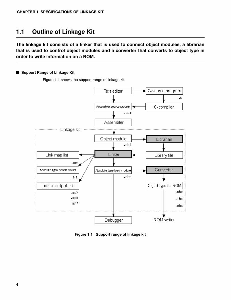
1.1 Outline of Linkage Kit
The linkage kit consists of a linker that is used to connect object modules, a librarianthat is used to control object modules and a converter that converts to object type inorder to write information on a ROM.
� Support Range of Linkage Kit
Figure 1.1 shows the support range of linkage kit.
Figure 1.1 Support range of linkage kit

1.2 Startup Procedure
5
1.2 Startup Procedure
Command line format and procedure for specification to execute the linkage kit (linker,librarian and converter) are described.
� Command line format
To specify the command line (startup command syntax) of the Softune linkage kit,
• Specify the filename and options as many times as required following the commandname.
Below, option is specified after the command name, but the position where option is described can be either before or after the filename. Refer to “Chapter 2 Options for more details”.
❍ Linker
The command name flnk***s differs depending upon the target CPU of the tool to be used.The command names of the respective target CPUs are shown below.
• In the case of FR family: flnk911s
• In the case of F2MC-16 family: flnk907s
• In the case of F2MC-8L family: flnk896s
Specify the object module filename to be input to <filename>.
Insert a space to specify two or more filenames.
A wild card such as *.obj can also be used. Expanding the wild card of filename dependson the OS. Refer to “Appendix G Differences Based on the OS”.
In linker, the target CPU must be specified using the -cpu option. Be sure to specify the -cpu option when executing the link processing.
❍ Librarian
The command name flib***s differs based on the target CPU of the tool to be used. Thecommand names of the respective target CPUs are shown below.
• In the case of FR family: flib911s
• In the case of F2MC-16 family: flib907s
• In the case of F2MC-8L family: flib896s
Specify the library file that is the target of editing, to <filename>.
In librarian, the target CPU must be specified using the -cpu option. Be sure to specify -cpu option when executing the library processing.
flnk***s [ Option ] ... < Filename >
flib***s [ Option ] ... < Filename >
CHAPTER 1 SPECIFICATIONS OF LINKAGE KIT
6
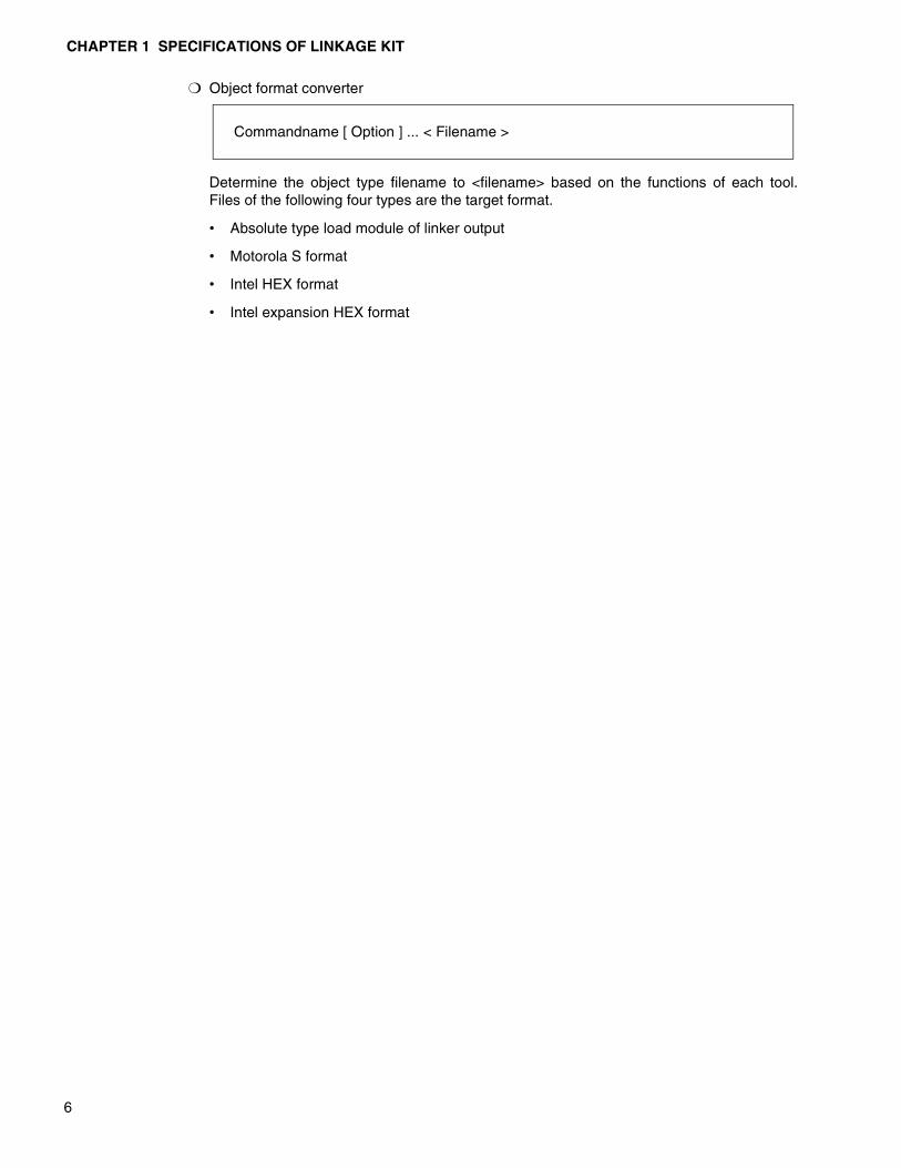
❍ Object format converter
Determine the object type filename to <filename> based on the functions of each tool.Files of the following four types are the target format.
• Absolute type load module of linker output
• Motorola S format
• Intel HEX format
• Intel expansion HEX format
Commandname [ Option ] ... < Filename >

1.3 Forced Termination
7
1.3 Forced Termination
When you want to suspend executing a program in the middle, press the CTRL key andthe C key at the same time. (Hereafter referred to as “Press CTR-C” .) Pressing CTRL-Cwill suspend a program.
� Forced termination
When a program processing is suspended by CTRL-C, the output result file cannot be created correctly. The work file that linkage kit uses during execution is cleared.

CHAPTER 1 SPECIFICATIONS OF LINKAGE KIT
8
1.4 End Code
Each tool of linkage kit returns the end status of its processing to OS as the end code.
� End code value and end status
Each linkage kit tool returns the end status of the processing (whether the processing has ended normally or an error has occurred ) to the OS as the end code. Table 1.4 shows the relation between the end codes and end status of processing.
Table 1.4 End codes and end status of processing
End code End status of processing
0 When ended normally or when an error of warning level occurs.
1 When an error of warning level occurs with the -cwno option specified
2 When an error occurs making it impossible to achieve the correct output result
3 When a fatal error occurs making it impossi-ble to continue processing
1.5 Startup Message
9
1.5 Startup Message
Linkage kit shows the startup message with the -V option. In the default processing,the startup message is not displayed.
� Startup message and the -V option
Linkage kit shows a message when errors are detected during processing but does not send a message when starting up in the default processing. If you want a message to be displayed during startup, use the -V option.
When you want to disable the -V option, specify the -XV option after the -V option. Refer to “3.2.4 Version number/Specifying message output (-V)” and “3.2.5 Version number/Suppression message output (-XV)” for more details.
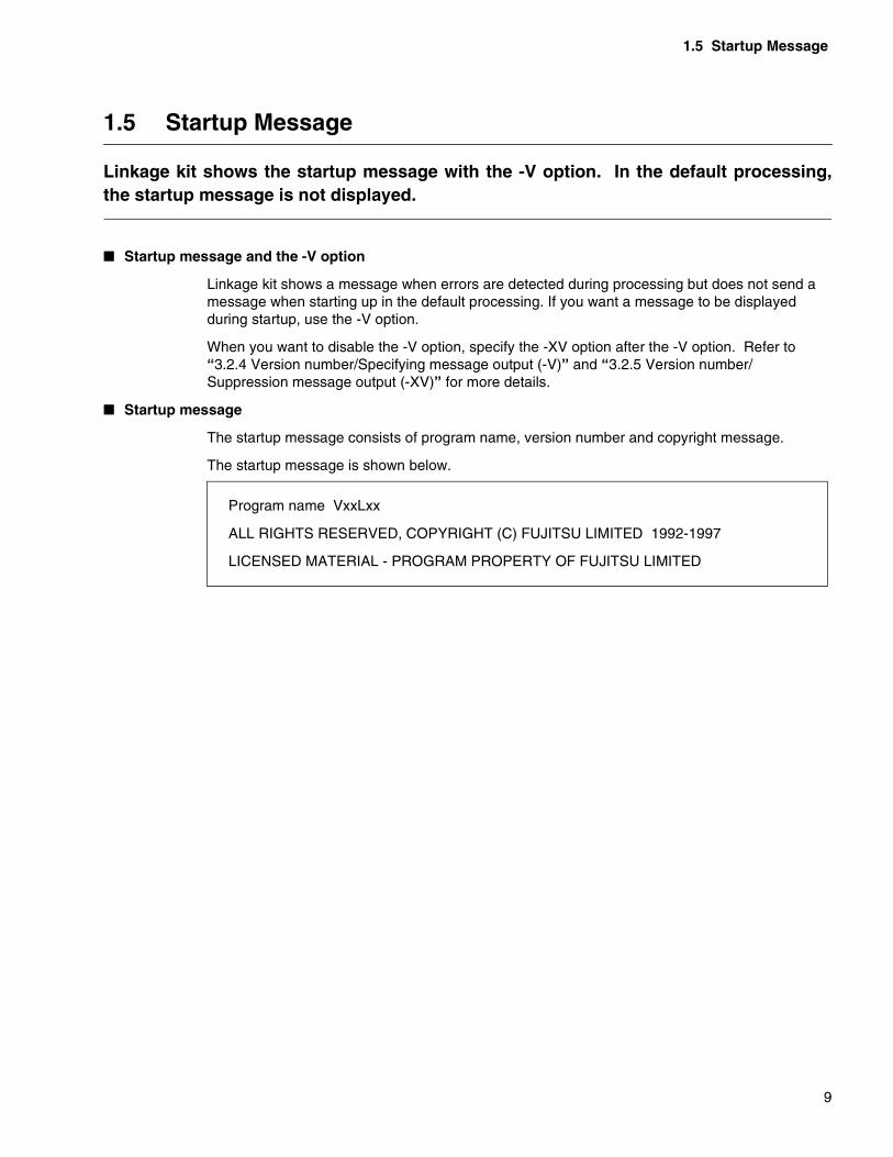
� Startup message
The startup message consists of program name, version number and copyright message.
The startup message is shown below.
Program name VxxLxx
ALL RIGHTS RESERVED, COPYRIGHT (C) FUJITSU LIMITED 1992-1997
LICENSED MATERIAL - PROGRAM PROPERTY OF FUJITSU LIMITED

CHAPTER 1 SPECIFICATIONS OF LINKAGE KIT
10
1.6 End Message
Linkage kit shows end message using the -cmsg option. The end message is notshown in the default processing.
� End message and -cmsg option
Linkage kit shows a message when errors are detected during processing, but no message appears to indicate the end in the default processing. If you want a message to appear at the end of processing, use the -cmsg option.
When you want to disable the -cmsg option, specify the -Xcmsg option after the -cmsg option. Refer to “3.2.6 Specifying display of end message (-cmsg)” and “3.2.7 Specifying suppression of end message display (-Xcmsg)”.
� End message
The end message shows tool names and errors.
Examples of the end message are shown below.
When errors do not occur
When errors occur
Program name COMPLITED FOUND NO ERROR
Program name COMPLITED FOUND ERROR

1.7 Help Message
11
1.7 Help Message
The following two kinds of messages are shown as help messages. • Command line description format• List of options at startup
� Help message
When nothing is specified other than the command name at startup, or when the -help option is specified at startup, program ends while showing the description format of command line and the list of startup options. Refer to “3.2.3 Help message display (-help)” for more details.
❍ Example of help message
The below figure shows an example of help message in the case of linker (English).
[Description of example]
*1: Command line syntax (startup procedure) is displayed.
*2: List of options and simple description.
This message can be shown in Japanese depending on the setting of the Environment variableFELANG (Refer to “1.10.2 FELANG”.)
usage : flnk911s [-option...] object [object...]
----------
options :-------- linker mode option --------
-------- library option --------set library file name
-r : -a :
-l filename [, ...] : -nl : -nd :
*1
*2
relocatable linking modeabsolute linking mode (default)
not search library filenot search default library file
...
CHAPTER 1 SPECIFICATIONS OF LINKAGE KIT
12
1.8 Identifiers
Linkage kit can handle the following seven kinds of identifiers. • Filename• Module name • Option name• Section name • Group name • ROM/RAM area name• Symbol name
� Types of characters consisting of identifiers
The following characters can be used as identifiers.
• Alphabetical letters
• Numbers
• Underscore (_)
Numbers cannot be used at the top of letters.
At the same, types of characters that can be used for the filename depends on the OS being used. The module name that is created from the filename also depends on the OS being used.
� Indicating identifiers
English uppercase and lowercase are indicated.
� Limiting the number of letters for identifiers
The number of letters for an identifier cannot exceed 255 letters (255 bytes). A character string exceeding this length is rolled off at 255 bytes.
� Displaying identifier name when outputting list
All identifier names up to 255 characters are not always displayed in the various list files that linkage kit creates.
Some of the longer identifier names only have the top 20 characters or so output and the remaining characters are not displayed.
Number of characters that can be displayed in one line increases or decreases depending on the setting of page width of a list. The format of easy viewing can be selected.
An option is also available to display the identifier name using multiple lines.

1.9 Filename Rules
13
1.9 Filename Rules
Filename of the input/output files complies with the limited use of characters that areset for the OS. There are cases in which the number of characters and code system must be taken intoaccount because the filename is also set in the object modules.
� Number of characters for the filename
The filename of the input/output files complies with the limited use of characters that are set for the OS.
� Character code of the filename
The source filenames of the C language and assembler are not only set as the source filename information in object module, but also set as module names.
The module name can be in English letters, numbers and the underscore symbol (_) only as described in “1.8 Identifier”. Therefore, the filenames that use Chinese characters or spaces must be modified specifying module name at the time of assembling.
❍ Filename and characters that can be used for the filename
(Windows 95/98/Me, Windows NT and Windows 2000 Version)
Alphabetical letters, numbers, Japanese kana characters, shift-JIS kanji code andsymbols except for the following:
\ / : ; , ∗ ? " < > |
When specifying a filename that includes spaces, enclose the filename with doublequotations (").
When specifying a director's name including spaces as the environment variable, do notenclose the filename with double quotations (").
CHAPTER 1 SPECIFICATIONS OF LINKAGE KIT
14
1.10 Environment Variables
Linkage kit support the following six kinds of environment variable.• TMP• FELANG• FETOOL• LIB911, LIB907, LIB896• OPT911, OPT907, OPT896• OPT
� TMP (Work directory)
TMP specifies work directory. Refer to “1.10.1 TMP (work directory)” for more details.
� FELANG
FELANG selects and specifies the message language. Refer to “1.10.2 FELANG” for more details.
� FETOOL
FETOOL specifies the directory in which the development tool is installed. Refer to “1.10.3 FETOOL” for more details.
� LIB911, LIB907, LIB896 (Library search directory)
LIB911, LIB907, and LIB896 specify the directory in which library is stored. Refer to “1.10.4 LIB911,LIB907, LIB896” for more details.
� OPT911, OPT907, OPT896 (Default option file storage directory)
OPT911, OPT907, OPT896 specify directory in which default option files of linker and librarian are stored. Refer to “1.10.5 OPT911,OPT907, OPT896” for more details.
� OPT (Default option file storage directory)
OPT specifies a directory in which the default option file of the object tool is stored. Refer to “1.10.6 OPT” for more details.
1.10 Environment Variables
15
1.10.1 TMP (Work directory)
TMP (work directory) specifies the work directory that the linkage kit uses duringexecution.The section below gives the description format, an explanation and an example ofspecification.
� TMP (work directory)
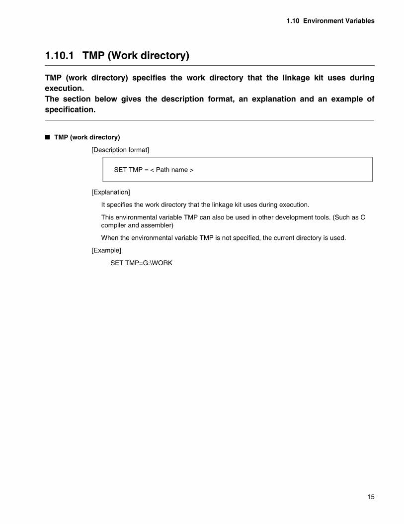
[Description format]
[Explanation]
It specifies the work directory that the linkage kit uses during execution.
This environmental variable TMP can also be used in other development tools. (Such as C compiler and assembler)
When the environmental variable TMP is not specified, the current directory is used.
[Example]
SET TMP=G:\WORK
SET TMP = < Path name >
CHAPTER 1 SPECIFICATIONS OF LINKAGE KIT
16
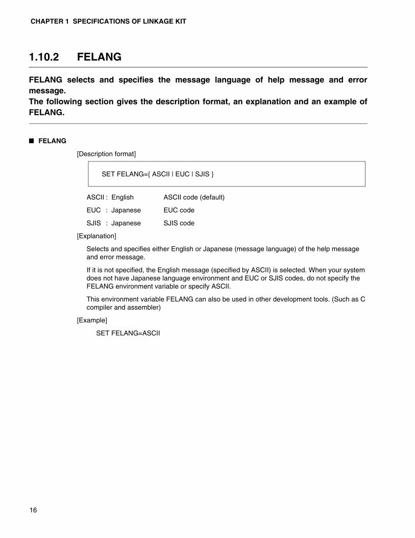
1.10.2 FELANG
FELANG selects and specifies the message language of help message and errormessage.The following section gives the description format, an explanation and an example ofFELANG.
� FELANG
[Description format]
ASCII : English ASCII code (default)
EUC : Japanese EUC code
SJIS : Japanese SJIS code
[Explanation]
Selects and specifies either English or Japanese (message language) of the help message and error message.
If it is not specified, the English message (specified by ASCII) is selected. When your system does not have Japanese language environment and EUC or SJIS codes, do not specify the FELANG environment variable or specify ASCII.
This environment variable FELANG can also be used in other development tools. (Such as C compiler and assembler)
[Example]
SET FELANG=ASCII
SET FELANG={ ASCII | EUC | SJIS }
1.10 Environment Variables
17
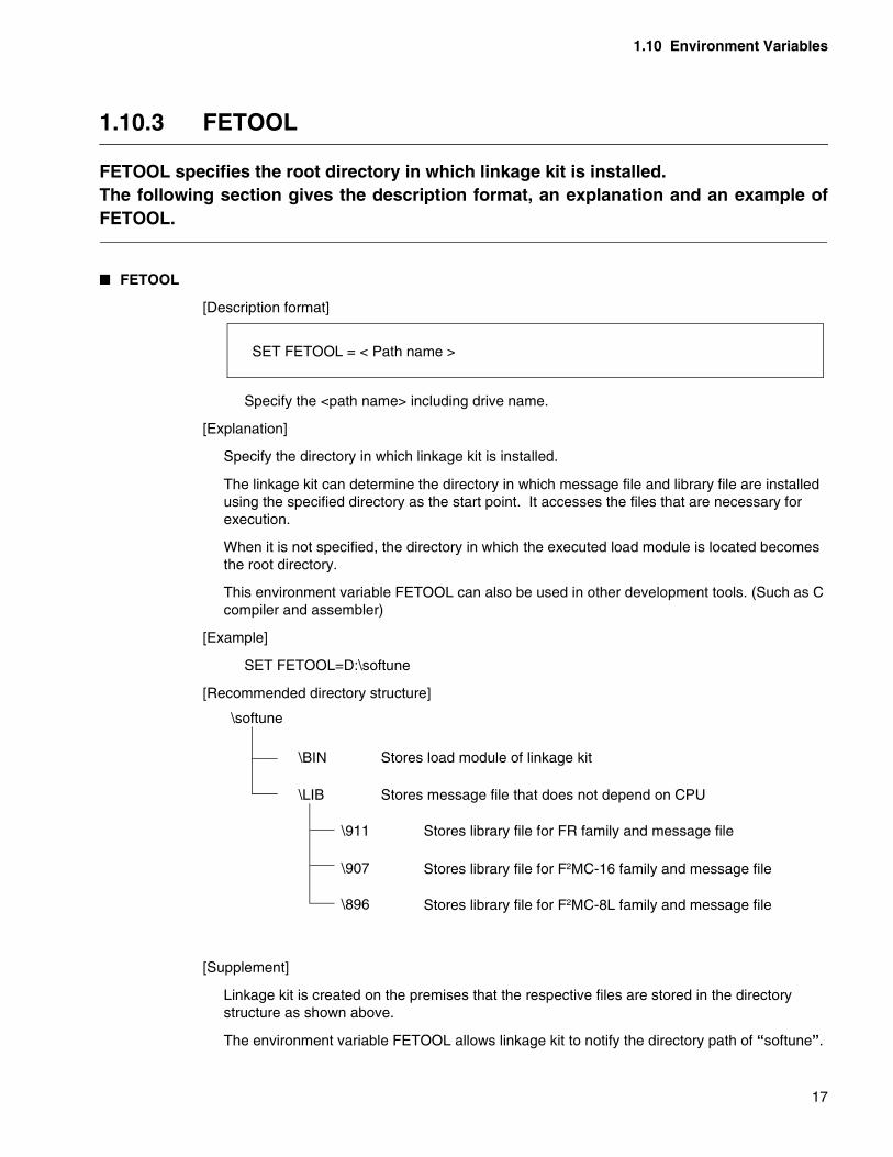
1.10.3 FETOOL
FETOOL specifies the root directory in which linkage kit is installed.The following section gives the description format, an explanation and an example ofFETOOL.
� FETOOL
[Description format]
Specify the <path name> including drive name.
[Explanation]
Specify the directory in which linkage kit is installed.
The linkage kit can determine the directory in which message file and library file are installed using the specified directory as the start point. It accesses the files that are necessary for execution.
When it is not specified, the directory in which the executed load module is located becomes the root directory.
This environment variable FETOOL can also be used in other development tools. (Such as C compiler and assembler)
[Example]
SET FETOOL=D:\softune
[Recommended directory structure]
[Supplement]
Linkage kit is created on the premises that the respective files are stored in the directory structure as shown above.
The environment variable FETOOL allows linkage kit to notify the directory path of “softune”.
SET FETOOL = < Path name >
\softune
\BIN
\LIB
Stores load module of linkage kit
Stores message file that does not depend on CPU
\911
\907
\896
Stores library file for FR family and message file
Stores library file for F2MC-16 family and message file
Stores library file for F2MC-8L family and message file
CHAPTER 1 SPECIFICATIONS OF LINKAGE KIT
18
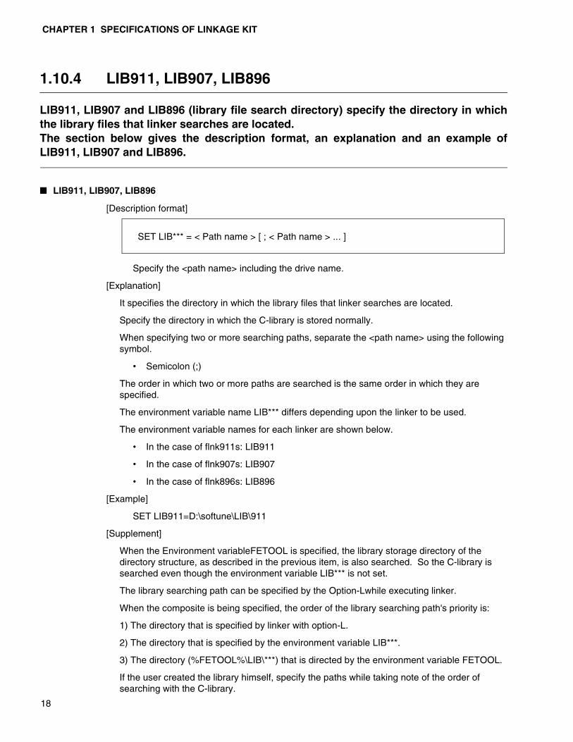
1.10.4 LIB911, LIB907, LIB896
LIB911, LIB907 and LIB896 (library file search directory) specify the directory in whichthe library files that linker searches are located.The section below gives the description format, an explanation and an example ofLIB911, LIB907 and LIB896.
� LIB911, LIB907, LIB896
[Description format]
Specify the <path name> including the drive name.
[Explanation]
It specifies the directory in which the library files that linker searches are located.
Specify the directory in which the C-library is stored normally.
When specifying two or more searching paths, separate the <path name> using the following symbol.
• Semicolon (;)
The order in which two or more paths are searched is the same order in which they are specified.
The environment variable name LIB*** differs depending upon the linker to be used.
The environment variable names for each linker are shown below.
• In the case of flnk911s: LIB911
• In the case of flnk907s: LIB907
• In the case of flnk896s: LIB896
[Example]
SET LIB911=D:\softune\LIB\911
[Supplement]
When the Environment variableFETOOL is specified, the library storage directory of the directory structure, as described in the previous item, is also searched. So the C-library is searched even though the environment variable LIB*** is not set.
The library searching path can be specified by the Option-Lwhile executing linker.
When the composite is being specified, the order of the library searching path's priority is:
1) The directory that is specified by linker with option-L.
2) The directory that is specified by the environment variable LIB***.
3) The directory (%FETOOL%\LIB\***) that is directed by the environment variable FETOOL.
If the user created the library himself, specify the paths while taking note of the order of searching with the C-library.
SET LIB*** = < Path name > [ ; < Path name > ... ]

1.10 Environment Variables
19
1.10.5 OPT911, OPT907, OPT896
OPT911, OPT907 and OPT896 (default option file storage directory) specifies thedirectory in which the default option files of linker and librarian are stored.The description format, an explanation and an example of OPT911, OPT907 andOPT896 are given below.
� OPT911, OPT907, OPT896
[Description format]
Specify the <path name> including the drive name.
[Explanation]
It specifies the directory in which the default option files that linker and librarian uses are stored.
The environment variable name OPT*** differs depending upon the target CPU. The environment variable names for target CPU are shown below.
• In the case of FR family : OPT911
• In the case of F2MC-16 family : OPT907
• In the case of F2MC-8L family : OPT896
This environment variable can be omitted.
When it is omitted, the default option files in the development environment directory are referred to.
The default option files in the development environment directory are shown below.
❍ Linker
• %FETOOL%LIB\911\FLNK911.OPT (In the case of FR family)
• %FETOOL%LIB\907\FLNK907.OPT (In the case of F2MC-16 family)
• %FETOOL%LIB\896\FLNK896.OPT (In the case of F2MC-8L family)
❍ Librarian
• %FETOOL%LIB\911\FLIB911.OPT (In the case of FR family)
• %FETOOL%LIB\907\FLIB907.OPT (In the case of F2MC-16 family)
• %FETOOL%LIB\896\FLIB896.OPT (In the case of F2MC-8L family)
[Example]
SET OPT911=D:\softune\LIB\911
SET OPT*** = < Path name >
CHAPTER 1 SPECIFICATIONS OF LINKAGE KIT
20
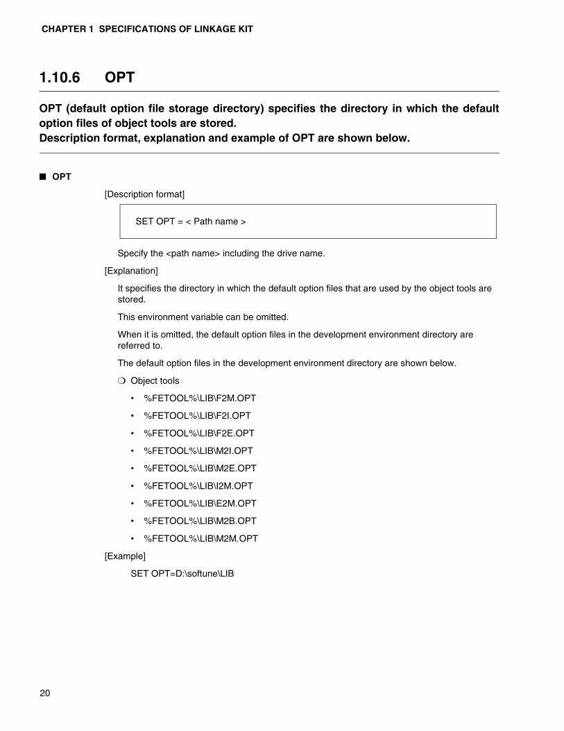
1.10.6 OPT
OPT (default option file storage directory) specifies the directory in which the defaultoption files of object tools are stored. Description format, explanation and example of OPT are shown below.
� OPT
[Description format]
Specify the <path name> including the drive name.
[Explanation]
It specifies the directory in which the default option files that are used by the object tools are stored.
This environment variable can be omitted.
When it is omitted, the default option files in the development environment directory are referred to.
The default option files in the development environment directory are shown below.
❍ Object tools
• %FETOOL%\LIB\F2M.OPT
• %FETOOL%\LIB\F2I.OPT
• %FETOOL%\LIB\F2E.OPT
• %FETOOL%\LIB\M2I.OPT
• %FETOOL%\LIB\M2E.OPT
• %FETOOL%\LIB\I2M.OPT
• %FETOOL%\LIB\E2M.OPT
• %FETOOL%\LIB\M2B.OPT
• %FETOOL%\LIB\M2M.OPT
[Example]
SET OPT=D:\softune\LIB
SET OPT = < Path name >

21
CHAPTER 2 OPTIONS
This section describes options of the linkage kit.
2.1 Option
2.2 Numeric Expression of Option Parameters
2.3 Notes and Evaluation When Option Is Specified
2.4 Specifying Options that Have the Inclusive or Contradictory Relation Each Other
2.5 Example of Specifying Command Lines

CHAPTER 2 OPTIONS
22
2.11 Option
An option consists of an option name and parameter. This section gives a synopsis ofan option and how to specify an option.
� Synopsis of option
The following section is a synopsis of an option.
Add a hyphen (-) to the top of the option name.
Insert a space to separate the option name from the parameter.
Whether the parameter is used or not used and the format of the parameter is defined in each option. Refer to the description of the respective options.
Pay attention to the following points when specifying an option.
• Large letters and small letters of alphanumeric letters must be distinguished whenspecifying option name.
• When a parameter needs an option, the parameters cannot be omitted entirely.
• When specifying two or more options, they cannot be specified as a group. Forexample, -a and -V as -aV is not acceptable.
• Spaces cannot be used in between hyphens and the option name.
� Parameter
Parameters are used to specify a filename or module name, which become the target of operation of an option. Two or more options are usually separated using a comma (,). However, symbols other than the comma (,) are also used when specifying sophisticated parameters. Refer to the description of each option for more details.
[Example]
-a
gets.obj,puts.obj,getc.obj,putc.obj
-sc CODE=0xC1000,DATA=0x1000
- Optionname [Parameter] ...

2.12 Numeric Expression of Option Parameters
23
2.12 Numeric Expression of Option Parameters
Decimal numbers and hexadecimal numbers can be used for the numeric expression ofoption parameters.
� Numeric Expression Of Option Parameters
When the numeric value of an option parameter starts with (0x), the numeral is recognized as a hexadecimal number. The other numerals are recognized as decimal numbers. Both large and small letters can be used for a to f of the hexadecimal notation.
[Example]
0x100... Hexadecimal notation (= 256)
100... Decimal notation (= 0x64)
0xff and 0xFF are the same.

CHAPTER 2 OPTIONS
24
2.13 Notes and Evaluation When Option Is Specified
When specifying options, some options need duplicated specification and some needsequence to specify them. In the linkage kit, the options are evaluated according to rules.
� Notes And Evaluation When Specified Option
The precautions and rules of evaluation when specifying options are described below.
❍ Options that require no parametersSpecifying only once is enough. Duplicated specifications have no meaning.
[Example]
-V : Specifying the message output
Duplicated specification like -V -V has no meaning and is error-free.
❍ Options that require parameters
When duplicated specification is required, there are different methods of evaluation asshown below.
• Only the last specification is effective.
• The order in which the specifications appear has specific intent, and all specificationsare effective.
• The order in which the specifications appear is irrelevant, and all specifications areeffective.
[ex. Only the last option which is specified is valid]
-o file.abs :Specifying the output file
When options are specified two or more times like -o file.abs -o file.rel, the specification that is entered last becomes effective. (In this case, file.rel becomes effective.)
[ex. Order of specifying options has meaning and all specifications are effective]
-l lib1.lib -l lib2.lib : Specifying the library retrieval (linker)
When options are specified in order, such as -l lib2.lib -l lib1.lib , order of retrieving library is inverted.
[ex. Order of specifying options has no meaning, yet all specifications are effective]
-sc code=0x1000 -sc data=0x200 : Specifying location of sections (linker)
When options are specified in order, such as -sc data=0x200 -sc code=0x1000 , all options are effective because the location of sections are individually independent.

2.14 Specifying Options that Have Inclusive or Contradictory Relation Each Other
25
2.14 Specifying Options that Have Inclusive or Contradictory Relation Each Other
When an option has an inclusive relation with other options, specifying an option ofhigher order becomes effective. When an option has a contradictory relation withother options, the option that is specified later becomes effective.
� Example of specifying an option that has an inclusive relation with other options
[Example]
Xm -pw 80 : Specifying suppression of outputting list and specifying page width
Since the option -pw is effective only in specifying output of list, this option itself has nomeaning when the option -Xm (suppression of outputting list) is specified. These optionshave no meaning even though the order is inverted, for example -pw 80 -Xm .
� Example of specifying an option that has a contradictory relation with other options
When an option that has a contradictory relation with other options is specified, the option that is specified later becomes effective.
[Example 1]
a -r
Specifying absolute format output and specifying relative format output (linker) -r becomes effective.
[Example 2]
-m mapfile -Xm
Specifying a name of list file and suppression of list output -m are canceled so that list output is not executed.
CHAPTER 2 OPTIONS
26
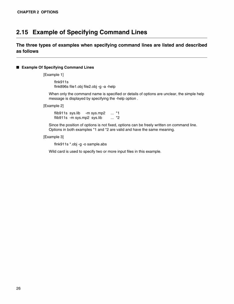
2.15 Example of Specifying Command Lines
The three types of examples when specifying command lines are listed and describedas follows
� Example Of Specifying Command Lines
[Example 1]
flnk911sflnk896s file1.obj file2.obj -g -a -help
When only the command name is specified or details of options are unclear, the simple help message is displayed by specifying the -help option .
[Example 2]
flib911s sys.lib -m sys.mp2 ... *1flib911s -m sys.mp2 sys.lib ... *2
Since the position of options is not fixed, options can be freely written on command line. Options in both examples *1 and *2 are valid and have the same meaning.
[Example 3]
flnk911s *.obj -g -o sample.abs
Wild card is used to specify two or more input files in this example.

27
CHAPTER 3 COMMON OPTIONS
Linkage kit has common options that can be used in any tools. These options are alsoprepared in C compiler and assembler.The options that are unique in this tool are also described in the respectiveparagraphs.
3.1 List of Common Options
3.2 Details of Common Options
CHAPTER 3 COMMON OPTIONS
28
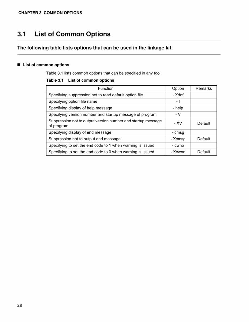
3.1 List of Common Options
The following table lists options that can be used in the linkage kit.
� List of common options
Table 3.1 lists common options that can be specified in any tool.
Table 3.1 List of common options
Function Option Remarks
Specifying suppression not to read default option file - XdofSpecifying option file name - fSpecifying display of help message - helpSpecifying version number and startup message of program - VSuppression not to output version number and startup message of program - XV Default
Specifying display of end message - cmsgSuppression not to output end message - Xcmsg Default
Specifying to set the end code to 1 when warning is issued - cwnoSpecifying to set the end code to 0 when warning is issued - Xcwno Default
3.2 Details of Common Options
29
3.2 Details of Common Options
The following section describes the common options that can be used in the linkagekit.
� -Xdof option
The -Xdof option cancels reading of the default option file. Refer to “3.2.1 Specifying Suppression of Default Option Files (-Xdof)” for more details.
� -f option
The -f option starts reading option from the file in which option is described. Refer to “3.2.2 Specifying Reading from Option File (-f)” for more details.
� -help option
The -help option displays the help message. Refer to “3.2.3 Specifying Help Message (-help)” for more details.
� -V option
The -V option outputs a message at program startup. This message is not displayed when the default processing is executed. Refer to “3.2.4 Specifying Version Number/Message Output (-V)” for more details.
� -XV option
The -XV option suppresses output of message during startup. Refer to “3.2.5 Suppression of Version Number/Message Output (-XV)” for more details.
� -cmsg option
The -cmsg option displays the end message of the program. Refer to “3.2.6 Specifying Display of End Message (-cmsg)” for more details.
� -Xcmsg option
The -Xcmsg option suppresses display of the end message. Refer to “3.2.7 Specifying Suppression to Display End Message (-Xcmsg)” for more details.
� -cwno option
When a warning is issued in this program, 1 is returned to OS as the end code. Refer to “3.2.8 Specifying End Code to 1 When Warning is Issued (-cwno)” for more details.
� -Xcwno option
When a warning is issued in this program, 0 is returned to OS as the end code. Refer to “3.2.9 Specifying End Code to 1 When Warning is Issued (-Xcmno)” for more details.
CHAPTER 3 COMMON OPTIONS
30
3.2.1 Specifying Suppression of Default Option File (-Xdof)
It cancels reading of default option file. When this option is not specified, default option file is always read.
� Specifying Suppression of Default Option File (-Xdof)
[Synopsis]
[Parameter]
None
[Description]
It cancels reading of default option file.
When this option is not specified, default option file is always read.
Refer to “4.5 Default Option File” for the option file.
[Note]
This option is valid when specified in the command line.
[Example]
flnk911s test.obj -Xdof
-Xdof

MEMO
31
CHAPTER 3 COMMON OPTIONS
32
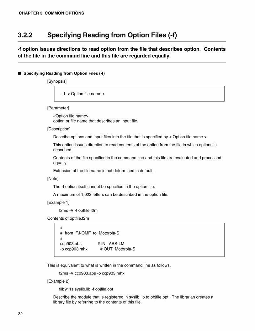
3.2.2 Specifying Reading from Option Files (-f)
-f option issues directions to read option from the file that describes option. Contentsof the file in the command line and this file are regarded equally.
� Specifying Reading from Option Files (-f)
[Synopsis]
[Parameter]
<Option file name>option or file name that describes an input file.
[Description]
Describe options and input files into the file that is specified by < Option file name >.
This option issues direction to read contents of the option from the file in which options is described.
Contents of the file specified in the command line and this file are evaluated and processed equally.
Extension of the file name is not determined in default.
[Note]
The -f option itself cannot be specified in the option file.
A maximum of 1,023 letters can be described in the option file.
[Example 1]
f2ms -V -f optfile.f2m
Contents of optfile.f2m
This is equivalent to what is written in the command line as follows.
f2ms -V ccp903.abs -o ccp903.mhx
[Example 2]
flib911s syslib.lib -f objfile.opt
Describe the module that is registered in syslib.lib to objfile.opt. The librarian creates a library file by referring to the contents of this file.
- f < Option file name >
## from FJ-OMF to Motorola-S#ccp903.abs # IN ABS-LM-o ccp903.mhx # OUT Motorola-S
3.2 Details of Common Options
33
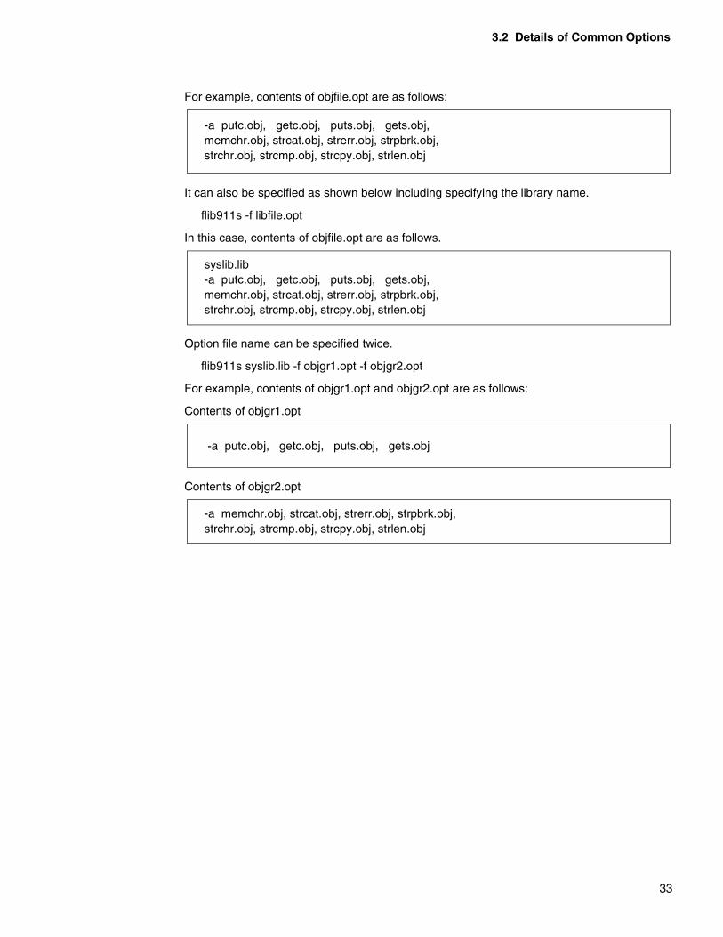
For example, contents of objfile.opt are as follows:
It can also be specified as shown below including specifying the library name.
flib911s -f libfile.opt
In this case, contents of objfile.opt are as follows.
Option file name can be specified twice.
flib911s syslib.lib -f objgr1.opt -f objgr2.opt
For example, contents of objgr1.opt and objgr2.opt are as follows:
Contents of objgr1.opt
Contents of objgr2.opt
-a putc.obj, getc.obj, puts.obj, gets.obj,memchr.obj, strcat.obj, strerr.obj, strpbrk.obj,strchr.obj, strcmp.obj, strcpy.obj, strlen.obj
syslib.lib-a putc.obj, getc.obj, puts.obj, gets.obj,memchr.obj, strcat.obj, strerr.obj, strpbrk.obj,strchr.obj, strcmp.obj, strcpy.obj, strlen.obj
-a putc.obj, getc.obj, puts.obj, gets.obj
-a memchr.obj, strcat.obj, strerr.obj, strpbrk.obj,strchr.obj, strcmp.obj, strcpy.obj, strlen.obj

CHAPTER 3 COMMON OPTIONS
34
3.2.3 Specifying Help Message (-help)
-help option issues directions to display the help message without executing theprogram. Format to specify the command line and option outline are displayed as helpmessage.
� Specifying Help Message (-help)
[Synopsis]
[Parameter]
None
[Description]
-help option briefly displays the format to specify the command line and list of options.
Help message is output to the standard output (stdout).
When the command name only is specified, the same help message is output.
When input file name and other options are specified, the help message only is displayed without executing programs when this option is specified.
- help
3.2 Details of Common Options
35
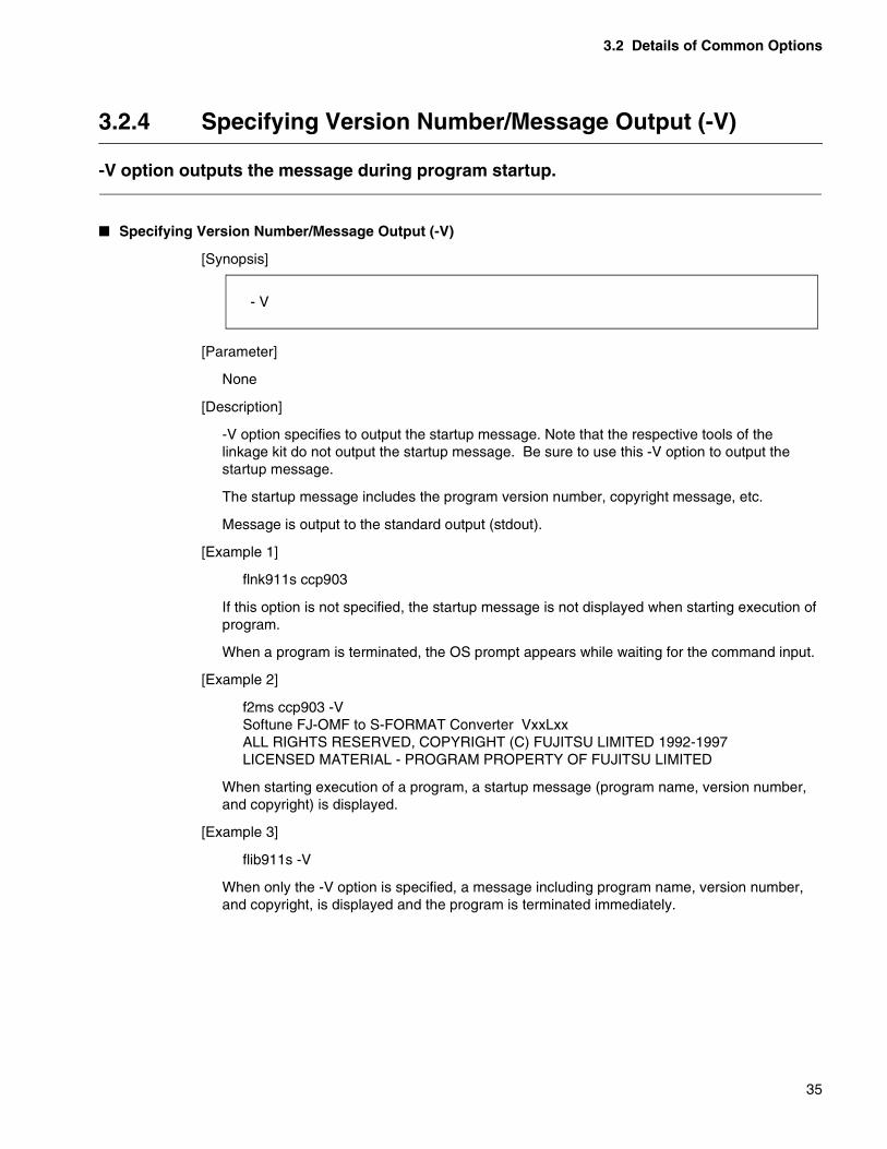
3.2.4 Specifying Version Number/Message Output (-V)
-V option outputs the message during program startup.
� Specifying Version Number/Message Output (-V)
[Synopsis]
[Parameter]
None
[Description]
-V option specifies to output the startup message. Note that the respective tools of the linkage kit do not output the startup message. Be sure to use this -V option to output the startup message.
The startup message includes the program version number, copyright message, etc.
Message is output to the standard output (stdout).
[Example 1]
flnk911s ccp903
If this option is not specified, the startup message is not displayed when starting execution of program.
When a program is terminated, the OS prompt appears while waiting for the command input.
[Example 2]
f2ms ccp903 -VSoftune FJ-OMF to S-FORMAT Converter VxxLxxALL RIGHTS RESERVED, COPYRIGHT (C) FUJITSU LIMITED 1992-1997LICENSED MATERIAL - PROGRAM PROPERTY OF FUJITSU LIMITED
When starting execution of a program, a startup message (program name, version number, and copyright) is displayed.
[Example 3]
flib911s -V
When only the -V option is specified, a message including program name, version number, and copyright, is displayed and the program is terminated immediately.
- V

CHAPTER 3 COMMON OPTIONS
36
3.2.5 Suppression of Version Number/Message Output (-XV)
-XV option disables the -V option. This prevents the startup message of a programfrom being output.
� Suppression of Version Number/Message Output (-XV)
[Synopsis]
[Parameter]
None
[Description]
Since the respective tools of the linkage kit do not output the startup message in default setting, specify the -V option to show the startup message.
-XV option is set to disable the -V setting.
[Example 1]
flnk911s ccp903flnk911s ccp903 -XV
The startup message is not output when starting execution of program in default setting.
The two options specified as above have the same meaning.
[Example 2]
f2ms -f lkit.opt ccp903 -XV
When a program is being executed using option files, sometimes setting of an option file might need to be changed temporarily.
When lkit.opt has -V option in it, contents of lkit.opt remain unchanged. However, -XV can be specified in order to cancel the -V option.
- XV

3.2 Details of Common Options
37
3.2.6 Specifying Display of End Message (-cmsg)
It displays the end message of the program.
� Specifying Display of End Message (-cmsg)
[Synopsis]
[Parameter]
Note
[Description]
It displays the end message of a program.
The linkage kit does not display the end message of a program in default setting.
[Example 1]
flnk911s ccp903
If this option is not specified, no message is output at the end of the program.
At the end of the program, the OS prompt appears waiting for input of next command.
[Example 2]
f2ms ccp903 -cmsgF2MS COMPLITED FOUND NO ERROR
At the end of the program, the end message (program name and presence or absence of errors) is displayed.
- cmsg
CHAPTER 3 COMMON OPTIONS
38
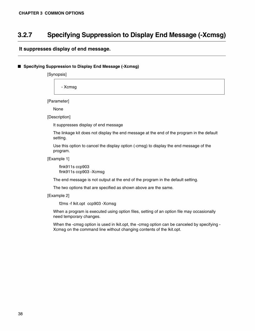
3.2.7 Specifying Suppression to Display End Message (-Xcmsg)
It suppresses display of end message.
� Specifying Suppression to Display End Message (-Xcmsg)
[Synopsis]
[Parameter]
None
[Description]
It suppresses display of end message
The linkage kit does not display the end message at the end of the program in the default setting.
Use this option to cancel the display option (-cmsg) to display the end message of the program.
[Example 1]
flnk911s ccp903flnk911s ccp903 -Xcmsg
The end message is not output at the end of the program in the default setting.
The two options that are specified as shown above are the same.
[Example 2]
f2ms -f lkit.opt ccp903 -Xcmsg
When a program is executed using option files, setting of an option file may occasionally need temporary changes.
When the -cmsg option is used in lkit.opt, the -cmsg option can be canceled by specifying -Xcmsg on the command line without changing contents of the lkit.opt.
- Xcmsg
3.2 Details of Common Options
39
3.2.8 Specifying End Code to 1 When Warning is Issued (-cwno)
It sets the end code to 1 when a warning is issued while the program is being executed.
� Specifying End Code to 1 When Warning is Issued (-cwno)
[Synopsis]
[Parameter]
None
[Description]
The end code is set to 1 when a warning is issued while the program is being executed.
Softune linkage kit sets the end code of 0 when a warning is issued.
[Example 1]
flnk911s ccp903 -cwno
When a warning is issued during execution of program, the end code to OS is 1.
[Example 2]
flnk911s ccp903
When a warning is issued during execution of program, the end code to OS remains 0.
- cwno
CHAPTER 3 COMMON OPTIONS
40
3.2.9 Specifying End Code to 0 When Warning is Issued (-Xcwno)
It sets the end code to 0 when warning is issued while the program is being executed.
� Specifying End Code to 0 When Warning is Issued (-Xcwno)
[Synopsis]
[Parameter]
None
[Description]
It returns the end code to 0, that is the default value, when warning only is issued during execution of program.
Softune linkage kit sets the end code to 0 when warning only is issued.
Use this option to cancel the option (-cwno) that sets the end code to 1 when warning is issued.
[Example 1]
flnk911s ccp903flnk911s ccp903 -Xcwno
When warning only is issued during execution of program, the end code is 0 in the default setting.
The two settings as specified above are the same.
[Example 2]
f2ms -f lkit.opt ccp903 -Xcwno
When a program is executed using option files, setting of an option file may occasionally need temporary changes.
When the -cwno option is used in lkit.opt, the -cwno option can be canceled by specifying -Xcwno on the command line without changing contents of the lkit.opt.
- Xcwno
41
CHAPTER 4 OPTION FILES
This section describes option files.
4.1 Option File
4.2 Specification to Continue in the Option File
4.3 Specifying Comment in the Option File
4.4 Example of Describing Option File
4.5 Default Option File

CHAPTER 4 OPTION FILES
42
4.1 Option File
In option files, file names and options required for processing could have been inputearlier in order to simplify input into command line every time.
� Option File
Option file is the file in which input file name and options that are input from the command line are described.
Syntax for description remains the same as that on the command line.
However, the following two items are added in option file.
• Comment statement can be described.
• Line feed is possible at any desired separating point.
Starts a comment statement with the comment symbol (#) and ends with line feed.
Comment statement and line feed symbol are handled equally as a space on command line.
� Execution by Specifying Option File
Since the number of characters to be input into command line is limited when specification alone is used, specification becomes impossible if there are too many file names and options to be specified. Also, it can decrease efficiency and affect operation due to input errors.
When process becomes formalized or when there are too many options and file names to be specified, the contents that are described in the file can be treated equally as the specification on the command line in order to save inputting work. Input the necessary file names and options into option file using text editor and execute it using the -f option.
[Example]
flib911s -f optfile
Content of option file “optfile”
The format of the statement in option line is the same as the one in command line. In the above example, options are written separately for each line. However, they can be written in one line.
The number of characters should be limited to 1023 bytes for one line.
This example describes not only options but also the library file (prg.lib)that is a target of editing.
As described above, all specifications that can be described in command line(excluding -f option and -Xdof option) can be described using the same format.
prg.lib-a main.obj-a send.obj,receive.obj,exchange.obj-a account.obj-m prg.mp2
prg.lib -a main.obj ..... -a account.obj -m prg.mp2
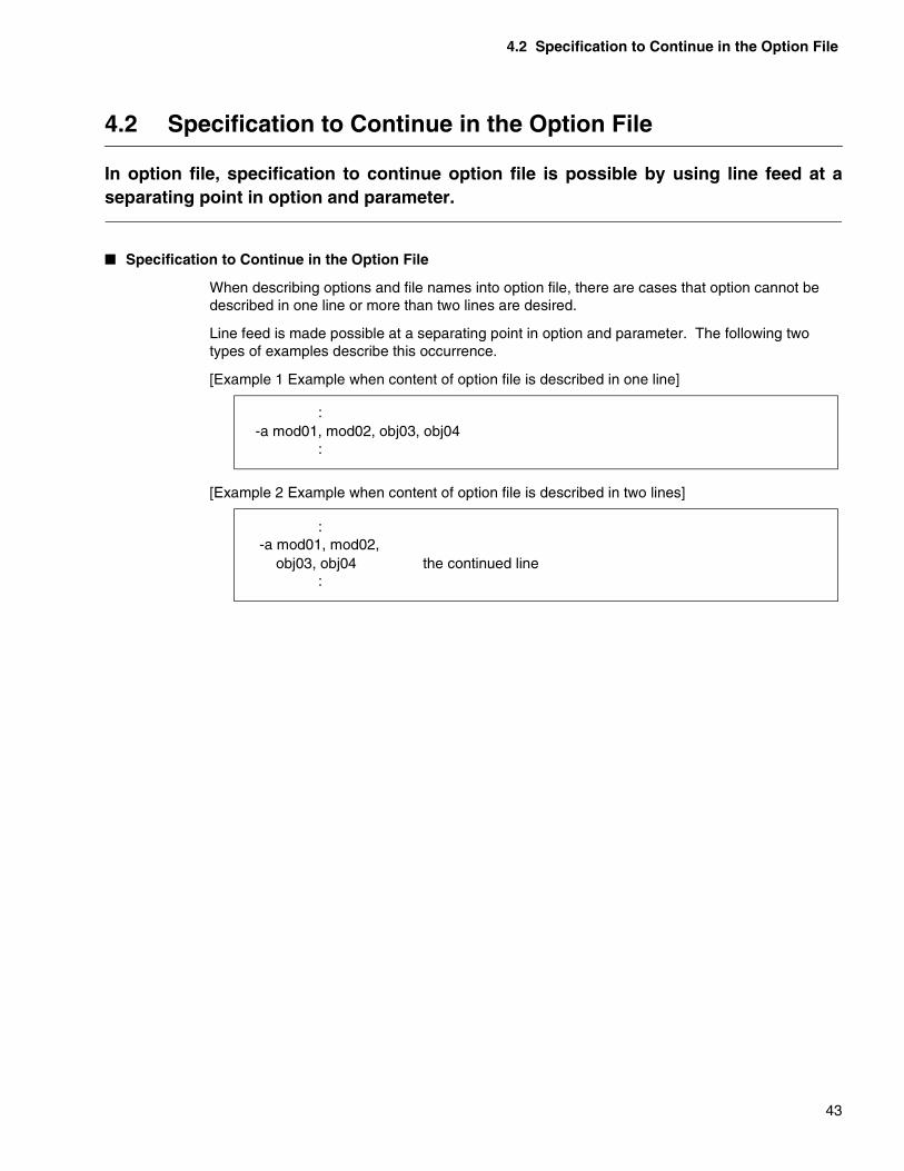
4.2 Specification to Continue in the Option File
43
4.2 Specification to Continue in the Option File
In option file, specification to continue option file is possible by using line feed at aseparating point in option and parameter.
� Specification to Continue in the Option File
When describing options and file names into option file, there are cases that option cannot be described in one line or more than two lines are desired.
Line feed is made possible at a separating point in option and parameter. The following two types of examples describe this occurrence.
[Example 1 Example when content of option file is described in one line]
[Example 2 Example when content of option file is described in two lines]
:-a mod01, mod02, obj03, obj04
:
-a mod01, mod02, obj03, obj04
:
:the continued line
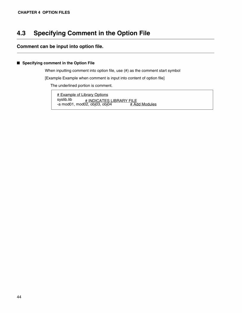
CHAPTER 4 OPTION FILES
44
4.3 Specifying Comment in the Option File
Comment can be input into option file.
� Specifying comment in the Option File
When inputting comment into option file, use (#) as the comment start symbol
[Example Example when comment is input into content of option file]
The underlined portion is comment.
syslib.lib# Example of Library Options
-a mod01, mod02, obj03, obj04 # INDICATES LIBRARY FILE
# Add Modules

4.4 Example of Describing Option File
45
4.4 Example of Describing Option File
The examples below show how to specify option file that can be handled equally as -amod01, mod02, obj03, obj04 in command line.
� Example of Describing Option File
-a mod01,mod02,obj03,obj04 Same
-a mod01, mod02 ,obj03 , obj04 Inserting a space befor
and after comma
-a mod01,mod02,obj03,obj04 # commentAdding comment to end
of statement
# comment lineInserting a comment
linent -a mod01,mod02,obj03,obj04
-a mod01,mod02,obj03, line feed after comma ,
continues the parameter obj04
-a mod01,mod02,obj03 line feed before comma ,
continues the parameter ,obj04
-a mod01,mod02,obj03, # comment inserting a comment
statement continues the
parameter obj04
-a line feed after -a
continues all parameters mod01,mod02,obj03,obj04
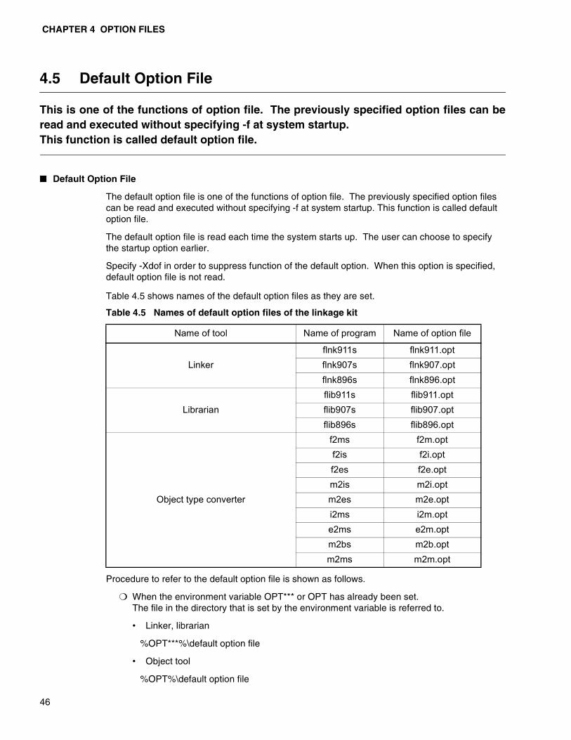
CHAPTER 4 OPTION FILES
46
4.5 Default Option File
This is one of the functions of option file. The previously specified option files can beread and executed without specifying -f at system startup. This function is called default option file.
� Default Option File
The default option file is one of the functions of option file. The previously specified option files can be read and executed without specifying -f at system startup. This function is called default option file.
The default option file is read each time the system starts up. The user can choose to specify the startup option earlier.
Specify -Xdof in order to suppress function of the default option. When this option is specified, default option file is not read.
Table 4.5 shows names of the default option files as they are set.
Procedure to refer to the default option file is shown as follows.
❍ When the environment variable OPT*** or OPT has already been set.The file in the directory that is set by the environment variable is referred to.
• Linker, librarian
%OPT***%\default option file
• Object tool
%OPT%\default option file
Table 4.5 Names of default option files of the linkage kit
Name of tool Name of program Name of option file
Linkerflnk911s flnk911.optflnk907s flnk907.optflnk896s flnk896.opt
Librarianflib911s flib911.optflib907s flib907.optflib896s flib896.opt
Object type converter
f2ms f2m.optf2is f2i.optf2es f2e.optm2is m2i.optm2es m2e.opti2ms i2m.opte2ms e2m.optm2bs m2b.optm2ms m2m.opt
4.5 Default Option File
47
❍ When the environment variable OPT*** or OPT has not been setThe default option file in the development environment directory is referred to.
• Linker, librarian
%FETOOL%\LIB\***\default option file
• Object tool
%FETOOL%\LIB\default option file
Note: When default option file cannot be found, the linkage kit does not issue errormessage.

48
MEMO

49
PART 2 LINKER
Part 2 describes the specifications, options, and output lists of a linker.
CHAPTER 5 SPECIFICATIONS OF A LINKER
CHAPTER 6 LINKER OPTIONS
CHAPTER 7 OUTPUT LIST FILE OF THE LINKER
CHAPTER 8 LINKER RESTRICTIONS AND Q&A

50
MEMO
51
CHAPTER 5 SPECIFICATIONS OF A LINKER
Chapter 5 describes the overview and functions of a linker.
5.1 Overview of a Linker
5.2 Functions of a Linker
5.3 Types of Sections
5.4 Combining Sections
5.5 Locating Sections
5.6 Automatically Locating Sections
5.7 Searching Libraries
5.8 ROM and RAM Areas
5.9 Sections to be Transferred from ROM to RAM
5.10 CPU Information File
5.11 Mixing of Objects for a F2MC-16 Family Linker

CHAPTER 5 SPECIFICATIONS OF A LINKER
52
5.1 Overview of a Linker
A linker is a tool that combines multiple object modules that are output by anassembler, then allocates memory location addresses. The purpose is to create a loadmodule in the executable form.
� Overview of a linker
The larger a program to be developed, the more difficult it becomes to describe everything in one source program.
Also, if you develop a program using a C compiler, you usually need to import library files in C.
A linker is used to combine multiple object modules that are related with each other, then allocate memory location addresses to create a load module in the executable form.
Figure 5.1 shows the relationship between a linker and input-output files.
Figure 5.1 Relationship between a linker and input-output files
Assembler
Linker
Relative format
objectAssemble listLibrary
Absolute format
assemble listRelative format
load module
Object contents
listAbsolute format
load module
(.lib) (.obj)
(.als)
(.lst)
(.mp1)
(.abs)
(.rel)
(.mpx)
(.mps)
(.mpm)

MEMO
53

CHAPTER 5 SPECIFICATIONS OF A LINKER
54
5.2 Functions of a Linker
A linker has many functions which can be roughly classified into the following fourgroups.• Control on input-output files and messages• Control on combining and locating sections• Control on searching alibraries• Setting entry addresses and symbol values
� Functions of a Linker
The following describes the overview of control and input-output files. For details, see Section 5.2.1, “Control on input-output files and messages”.
• There are the following four types of input files:
-- Object module file that an assembler outputs
-- List file
-- Relative format load module file that a linker outputs
-- Library file
• Object module files and load module files are processed in the order that they arewritten on a command line or in an option file.
• There are the following three types of output files:
-- Absolute format load module file that is the final objective
-- Relative format load module that can be input again
-- Link map list file
• The output load module format (absolute or relative) may be specified and the outputfile name may be changed.
• For a map list, the number of lines per page and the width of a page may be changed.
• Specify an option to output one of the following four types of files.
To output these files, the link load module must be in the absolute format.
-- Absolute format assemble list file is created by adding to the absolute format a list file that an assembler has output.
-- External symbol cross-reference information list that shows the cross-reference between external defined symbols and reference symbols used in modules
-- Local symbol information list that shows the information on local symbols used in each module
-- Section detailed map list that shows section location addresses in each module
• Messages consist of startup messages including the program version number, helpmessages briefly describing how to use the program, and error messages. You canspecify whether or not to output a startup message and the level of detecting a warningstatus.
5.2 Functions of a Linker
55
� Control on combining and locating sections
The following is an overview of the control on combining and locating sections. For details, see Section 5.2.2, “Control on combining and locating sections”.
• You can make sure that a section is not located outside the specified area byspecifying the address ranges of ROM and RAM.
• When specifying sections, you may create a group of multiple sections to process themin a batch or select sections according to attributes.
• You may use a wildcard to specify sections. This will allow you to easily specifysections to be combined or located when many sections are involved.
• The function to support creating a ROM is provided.
• The sections may be automatically located to the specified ROM and RAM areas.
� Control on searching libraries
The following describes in detail the control on searching a library. For details, see Section 5.2.3, “Control on searching libraries”.
• When a program is developed in C, the runtime library in C required for linking can beautomatically identified and combined (searching the default library file).
• Multiple libraries created by the user may be searched.
• The library file to be searched may be specified for each symbol.
• Library searching may be inhibited.
� Setting entry addresses and symbol values
A value may be temporarily allocated external to an undefined external symbol or an entry address may be temporarily set. For details, see Section 5.2.4, “Setting entry addresses and symbol values”.

CHAPTER 5 SPECIFICATIONS OF A LINKER
56
5.2.1 Control on Input-Output Files and Messages
Section 5.2.1 describes those linker functions that control the input-output files andmessages.
� Specifying input object files
The input files for a linker include object module files that an assembler outputs and relative format load module files that a linker outputs.
All the input files must be specified, which can be facilitated by using wildcard.
� Specifying an output load module file name
An output load module file name created after linking is based on the file name of the module that a linker first inputs.
This function is provided to change the default output file name because it is often inappropriate as a name to represent the entire linking result.
In particular, the output file name is difficult to understand if a file name is specified using a wildcard. In such a case, you are recommended to specify a file name.
� Inheriting debugging information
Information on symbols and source files is required for debugging.
If debugging information is specified to be created (-g option) in C or for an assembler, an object module will contain debugging information.
A linker inherits this debugging information. You can decide either to output it into a load module or to delete it.
� Specifying the output format
Use this function to specify creating an absolute or relative format load module as a result of linking.
� Specifying a list file name
A list file name is created based on the output object file name. Use this function to change this default file name.
� Changing the format of a list file
Page control is performed when a list file is created. You may change the number of lines per page and number of characters per line.
A long symbol name is truncated to fit into one line. You can specify to display the name exactly as you defined it.
� Selecting the warning check level
A warning indicates a minor error. A warning message is issued if a problem occurs but the linking processing may be continued. Some warnings must be resolved and others may be ignored. Use this function to select the check level.
� Selecting whether or not to display a startup message
You can select whether or not to display the tool name and the copyright at startup.

5.2 Functions of a Linker
57
� Selecting whether or not to display a termination message.
You can select whether or not to display a termination message.
CHAPTER 5 SPECIFICATIONS OF A LINKER
58
5.2.2 Control on Combining and Locating Sections
Section 5.2.2 describes those linker functions used to control combining and locatingsections.
� Specifying ROM and RAM areas
Defining an area name by specifying the address range of the ROM and RAM areas allows you to use this area name instead of an address when specifying where to locate a section. It also allows you to make sure that the section is not located outside the range.
To have sections automatically located, locate them in this area range.
� Specifying the order of locating sections and the location addresses
All the sections may be located in any area in any order. To specify a section name, use a wildcard.
Additionally, you can specify sections using a name plus a section contents type. Use these together with a wildcard to collect only the sections with the same contents type (code, data, etc.).
� Creating a group of sections
A linker combines and locates sections. If many sections are used to create a program, specifying where to locate the sections will be troublesome.
Multiple sections may be handled as if they are one section by giving them a group name and collecting them in continuous areas.
� Support for creating a ROM
When developing a program in C, a variable with an initial value is created. The variable must often be rewritten and other processing must be performed.
In an application to be imported, the initial value data must be placed in ROM and transferred to RAM before the application is executed.
This function enables these operations. For details, see Section 5.9, “Sections to be Transferred from ROM to RAM”.

5.2 Functions of a Linker
59
5.2.3 Control on Searching Libraries
Section 5.2.3 describes those linker functions that control searching for a library.
� Specifying a path to search a library
To specify a path to search a library, specify the directory containing the C library in an environment variable. However, specify the path if a library created by the user is stored in another directory.
� Specifying a library file to be searched
As the library to be searched, specify the name of a library file created by the user in addition to the runtime libraries provided by a C compiler.
� Specifying a library file to be searched for each symbol
If, in the linking processing, multiple library files are searched and you know that the same external symbol is contained in the libraries, use this function to explicitly specify which library module should be linked.
� Inhibiting the search for a library
You can disable the search of a default library or all the libraries.
CHAPTER 5 SPECIFICATIONS OF A LINKER
60
5.2.4 Setting Entry Addresses and Symbol Values
Section 5.2.4 describes those linker functions that set entry addresses and symbolvalues.
� Specifying an entry address
Use this function to set in an output load module an address at which to start executing the program.
� Setting an external symbol value
An error occurs if an external symbol is not defined after linking because of an incomplete program or an incorrect external symbol name.
Use this function to set a temporary value to temporarily remove this error and create a load module executable for the time being.

MEMO
61

CHAPTER 5 SPECIFICATIONS OF A LINKER
62
5.3 Types of Sections
The minimum unit that a linker can combine is a section.Depending on the purpose of using sections in a program, they are located andcombined differently.Section 5.3 describes section names, contents types, location attributes, andcombination attributes.
� Section name
A section name is used to identify a section.
� Types of section contents
Depending on the purpose of usage, there are the following five types of section contents:
An assembler determines the attributes of execution, read, or write. Table 5.3a shows the section types.
� Section location attribute
There are two section location attributes representing whether or not the section is relocatable. Table 5.3b shows the section location attributes.
� Section combination attribute
There are two section combination attributes representing whether the section is shared or combined. Table 5.3c shows the section combination attributes.
Table 5.3a Section types
Type Description Attribute
CODE Program code area Executable, ReadDATA Variable area Read, WriteCONST Area of variable with initial value ReadSTACK Stack area Read, WriteIO I/O area Read, WriteDIR direst area (F2MC family) Read, WriteDIRCONST direct area with initial vlues (F2MC family) Read
Table 5.3b Section location attributes
Attribute Description
ABS Section in which absolute addresses are specifiedREL Relocatable section
Table 5.3c Section combination attributes
Attribute Description
PUBLIC Sections are combined in succession.COMMON Sections are combined and overlapped at the same address.

5.3 Types of Sections
63
� Section identification
A linker handles the sections with the same section name, contents type, and combination attribute and the REL attribute as the same section.
A linker does not locate a section with the ABS attribute.
Since a linker identifies a section by the section name, do not define sections with the same section name and different types of contents and attributes.
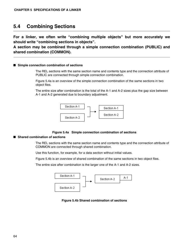
CHAPTER 5 SPECIFICATIONS OF A LINKER
64
5.4 Combining Sections
For a linker, we often write “combining multiple objects” but more accurately weshould write “combining sections in objects”.A section may be combined through a simple connection combination (PUBLIC) andshared combination (COMMON).
� Simple connection combination of sections
The REL sections with the same section name and contents type and the connection attribute of PUBLIC are connected through simple connection combination.
Figure 5.4a is an overview of the simple connection combination of the same sections in two object files.
The entire size after combination is the total of the A-1 and A-2 sizes plus the gap size between A-1 and A-2 generated due to boundary adjustment.
Figure 5.4a Simple connection combination of sections
� Shared combination of sections
The REL sections with the same section name and contents type and the connection attribute of COMMON are connected through shared combination.
Use this function, for example, for a data section without initial values.
Figure 5.4b is an overview of shared combination of the same sections in two object files.
The entire size after combination is the larger one of the A-1 and A-2 sizes.
Figure 5.4b Shared combination of sections

5.5 Locating Sections
65
5.5 Locating Sections
A linker combines the same sections and then determines the location addresses ofsections. Section 5.5 describes how a linker locates sections including a case wherethe user specifies the addresses.
� Links of sections
Only relative sections may be combined or located.
Absolute sections may not be combined or located.
Sections are combined or located in the following way:
1) The same sections are collected from object modules.
2) These sections are combined according to their combination attributes.
3) Then the sections are located.
Sections are located according to an option concerning a section location order, if any specified, or otherwise, according to the order in which they appear in an object file.
For details, see Section 5.5.1, “Example of location when the order of combining sections is not specified”, 5.5.2, “Example of location when the order of combining sections is specified”, and 5.5.3, “Example of location when the section group is specified”.

CHAPTER 5 SPECIFICATIONS OF A LINKER
66
5.5.1 Example of Location when the Order of Combining Sections is not Specified
Section 5.5.1 describes an example of location when the order of combining sections isnot specified according to Figure 5.5a.
� Example of location when the order of combining sections is not specified
If Modules 1, 2, and 3 are input in this order, Sections A, B, and C appear in this order. Therefore, the location addresses are A, B, and C in ascending order.
Note:Sections A and C have the PUBLIC attribute and Section B the COMMON attribute.
Figure 5.5a Example of location when the order of combining sections is not specified

5.5 Locating Sections
67
5.5.2 Example of Location when the Order of Combining Sections is Specified
Section 5.5.2 describes an example of location when the order of combining sections isspecified according to Figure 5.5b.
� Example of location when the order of combining sections is specified
If Modules 1, 2, and 3 are input in this order, Sections A, B, and C appear in this order. However, the order of location is specified as A, C, and B.
Note:Sections A and C have the PUBLIC attribute and Section B the COMMON attribute.
Figure 5.5b Example of location when the order of combining sections is specified
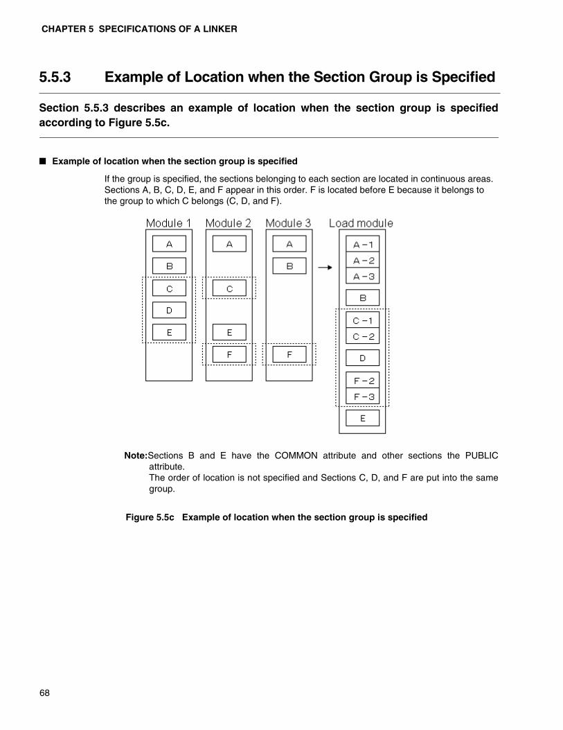
CHAPTER 5 SPECIFICATIONS OF A LINKER
68
5.5.3 Example of Location when the Section Group is Specified
Section 5.5.3 describes an example of location when the section group is specifiedaccording to Figure 5.5c.
� Example of location when the section group is specified
If the group is specified, the sections belonging to each section are located in continuous areas. Sections A, B, C, D, E, and F appear in this order. F is located before E because it belongs to the group to which C belongs (C, D, and F).
Note:Sections B and E have the COMMON attribute and other sections the PUBLICattribute.The order of location is not specified and Sections C, D, and F are put into the samegroup.
Figure 5.5c Example of location when the section group is specified

5.6 Automatically Locating Sections
69
5.6 Automatically Locating Sections
Normally, a linker determines the section location addresses according to the locationspecification provided by the user. However, you can have the linker automaticallydetermine section location addresses by specifying the -AL option.If any absolute section exists when sections are located in the area specified in the -raor -ro option, the relocatable sections are located so that the location addresses do notoverlap. At this time, the sections with a larger alignment value or size are locatedbefore others so that the optimal location is achieved and the available area is thesmallest.
� Automatically Locating Sections
This linker supports automatically locating the following two types of sections:
• Automatically locating sections when -AL 1 is specified
• Automatically locating sections when -AL 2 is specified
For details of automatically allocating sections, see Sections 5.6.1, “Automatically locating sections when -AL 1 is specified”, and 5.6.2, “Automatically locating sections when -AL 2 is specified”.

CHAPTER 5 SPECIFICATIONS OF A LINKER
70
5.6.1 Automatically Locating Sections when -AL 1 is Specified
If -AL 1 is specified, a linker locates the relocatable sections so that their locationaddresses do not overlap with the absolute sections existing in the area.
� Determining location addresses
The sections with the area name specified in the -sc option may be automatically located.
Sections with larger alignment and values are located before others. For sections with the same alignment and values, ones with a larger size are located before others.
Table 5.6a shows the alignment values and sizes of sections.
For example, the order of locating sections shown in Table 5.6a is determined as follows:
1) Sections with an alignment value of 4 (code4 and code5) are located before those with an alignment value of 2 (code1,code2,and code3).
2) The code5 sections, being larger in size, are located before the code4 sections.
Therefore, the order of locating sections shown in Table 5.6a is as shown in Table 5.6b.
Sections are located in the smallest available area where they can be located.
Table 5.6a Alignment values and sizes of sections
Section name Alignment value Size
code1 2 0x0180code2 2 0x0100code3 2 0x0200code4 4 0x0100code5 4 0x0200code6 2 0x0020
Table 5.6b Alignment values and sizes of sections
Order of location processing Section name
Alignment value Size
1 code5 4 0x02002 code4 4 0x01003 code3 2 0x02004 code1 2 0x01805 code2 2 0x01006 code6 2 0x0020

5.6 Automatically Locating Sections
71
� Example of location when -AL 1 is specified
The following is an example of location when the linker options are specified and the sections contents are as shown below (Figure 5.6a and Table 5.6c).
Figure 5.6a Option specification for a linker
Figure 5.6b shows an example of location when -AL 1 is specified.
As shown in this example, specify -AL 1 to have a linker optimally locate sections in the specified area so that they do not overlap with absolute sections and the available area is the smallest.
Figure 5.6b Example of location when -AL 1 is specified
Table 5.6c Contents of sections
Section name
Location attribute Address range Alignment
value Size
code1 REL - 2 0x0180code2 REL - 2 0x0100code3 REL - 2 0x0200code4 REL - 4 0x0100code5 REL - 4 0x0200code6 REL - 2 0x0020
AbsSec ABS 0x1120-0x121F 0 0x0100
-ro ROM=0xC1000/0xC18FF
-sc code1+code2+code3+code4+code5+code6=ROM
-AL 1
:
code4
code6
AbsSec
code5
code3
code1
code2
Unused (available)
0xC1000
0xC1100
0xC1420
0xC1120
0xC1620
0xC17A0
0xC1220
0xC18A0
0xC18FFROM area specified in -sc
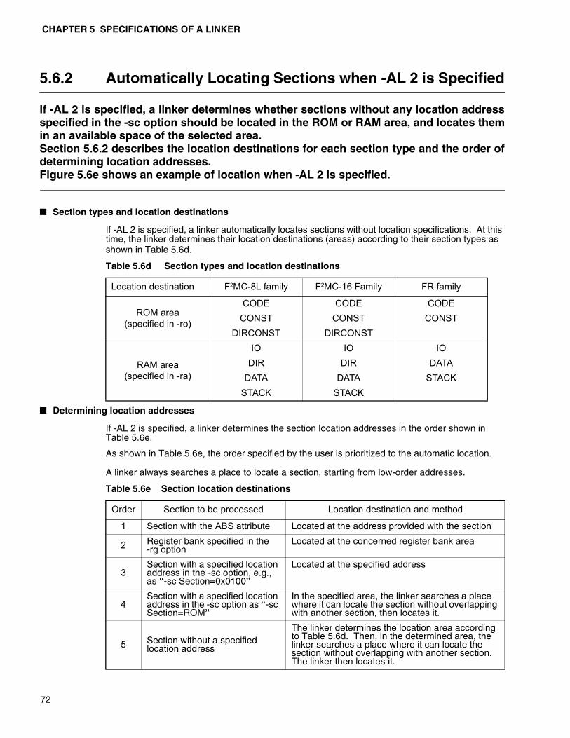
CHAPTER 5 SPECIFICATIONS OF A LINKER
72
5.6.2 Automatically Locating Sections when -AL 2 is Specified
If -AL 2 is specified, a linker determines whether sections without any location addressspecified in the -sc option should be located in the ROM or RAM area, and locates themin an available space of the selected area.Section 5.6.2 describes the location destinations for each section type and the order ofdetermining location addresses.Figure 5.6e shows an example of location when -AL 2 is specified.
� Section types and location destinations
If -AL 2 is specified, a linker automatically locates sections without location specifications. At this time, the linker determines their location destinations (areas) according to their section types as shown in Table 5.6d.
� Determining location addresses
If -AL 2 is specified, a linker determines the section location addresses in the order shown in Table 5.6e.
As shown in Table 5.6e, the order specified by the user is prioritized to the automatic location.
A linker always searches a place to locate a section, starting from low-order addresses.
Table 5.6d Section types and location destinations
Location destination F2MC-8L family F2MC-16 Family FR family
ROM area(specified in -ro)
CODE CODE CODECONST CONST CONST
DIRCONST DIRCONST
RAM area (specified in -ra)
IO IO IODIR DIR DATA
DATA DATA STACKSTACK STACK
Table 5.6e Section location destinations
Order Section to be processed Location destination and method
1 Section with the ABS attribute Located at the address provided with the section
2 Register bank specified in the -rg option
Located at the concerned register bank area
3Section with a specified location address in the -sc option, e.g., as “-sc Section=0x0100”
Located at the specified address
4Section with a specified location address in the -sc option as “-sc Section=ROM”
In the specified area, the linker searches a place where it can locate the section without overlapping with another section, then locates it.
5 Section without a specified location address
The linker determines the location area according to Table 5.6d. Then, in the determined area, the linker searches a place where it can locate the section without overlapping with another section. The linker then locates it.
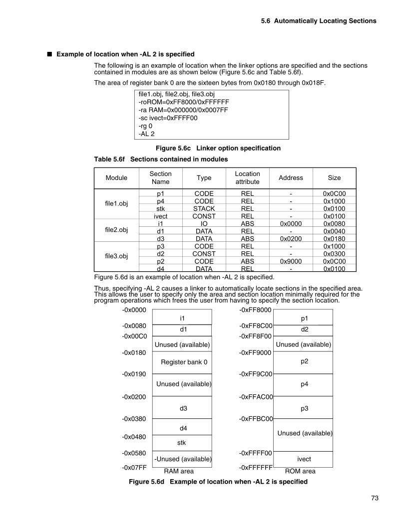
5.6 Automatically Locating Sections
73
� Example of location when -AL 2 is specified
The following is an example of location when the linker options are specified and the sections contained in modules are as shown below (Figure 5.6c and Table 5.6f).
The area of register bank 0 are the sixteen bytes from 0x0180 through 0x018F.
Figure 5.6c Linker option specification
Figure 5.6d is an example of location when -AL 2 is specified.
Thus, specifying -AL 2 causes a linker to automatically locate sections in the specified area. This allows the user to specify only the area and section location minimally required for the program operations which frees the user from having to specify the section location.
Figure 5.6d Example of location when -AL 2 is specified
Table 5.6f Sections contained in modules
Module Section Name Type Location
attribute Address Size
file1.objp1 CODE REL - 0x0C00p4 CODE REL - 0x1000stk STACK REL - 0x0100
ivect CONST REL - 0x0100
file2.obji1 IO ABS 0x0000 0x0080d1 DATA REL - 0x0040d3 DATA ABS 0x0200 0x0180
file3.objp3 CODE REL - 0x1000d2 CONST REL - 0x0300p2 CODE ABS 0x9000 0x0C00d4 DATA REL - 0x0100
file1.obj, file2.obj, file3.obj-roROM=0xFF8000/0xFFFFFF-ra RAM=0x000000/0x0007FF-sc ivect=0xFFFF00-rg 0-AL 2
Unused (available)
Register bank 0
stk
-Unused (available)
-0x0000
-0x0080
-0x0190
-0x00C0
-0x0200
-0x0380
-0x0180
-0x0480
-0x0580
RAM area
i1
d1
Unused (available)
d3
d4
-0x07FF
Unused (available)
ivect
-0xFF8000
-0xFF8C00
-0xFF9C00
-0xFF8F00
-0xFFAC00
-0xFFBC00
-0xFF9000
-0xFFFF00
ROM area
p1
d2
p3
-0xFFFFFF
p2
Unused (available)
p4

CHAPTER 5 SPECIFICATIONS OF A LINKER
74
5.7 Searching Libraries
Specify a library file to be searched by a linker in one of the following three ways:• Setting the default library• Specification in the -l option• Specification in the -el option
� Specifying a library to be searched
A linker, if any undefined symbol remains when the specified input files have been combined, searches a library file to solve this status.
The linker searches library files recursively so as not to omit anything in the search.
Specify a library file to be searched in one of the following three ways:
❍ Setting the default library
If a program is written in C, a C library is required at the time of linking.
It is troublesome for the user to specify the library files to be searched at the time oflinking. Furthermore, if the user specifies wrong files, unintended modules will becombined.
To prevent this, a C compiler uses an assembler's pseudo instructions to provide theinformation on library file names to be selected. Then, the assembler sets the informationin an object module.
A library file name thus set in the object module to be linked is called the default library.
❍ Specification in the -l option
To search a library file not defined as the default library, you must specify it at the time oflinking.
If you want to create and link a library file, either write a pseudo instruction to specify alibrary using an assembler, or specify it in the -l option when you start up a linker.
For details on the -l option, see Section 6.2.19, “Specifying a library file to be searched (-l).”
❍ Specification in the -el option
One or more library files may be specified.
Different library files may contain an external defined symbol with the same name. (Avoidsuch a status because it may cause a malfunction.)
The -el option is used to identify for each symbol a library file name in which to search asymbol. For details, see Section 6.2.21, “Specifying a library for each symbol (-el)”.
� Order of searching a library file
A linker solves a symbol with the -el option specified, then searches libraries in the order specified in the -l option Lastly, it searches the default library. This series of searches will be repeated until no more modules are imported from library files.
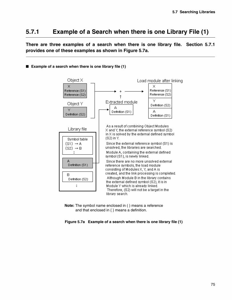
5.7 Searching Libraries
75
5.7.1 Example of a Search when there is one Library File (1)
There are three examples of a search when there is one library file. Section 5.7.1provides one of these examples as shown in Figure 5.7a.
� Example of a search when there is one library file (1)
Note: The symbol name enclosed in ( ) means a reference and that enclosed in { } means a definition.
Figure 5.7a Example of a search when there is one library file (1)

CHAPTER 5 SPECIFICATIONS OF A LINKER
76
5.7.2 Example of a Search when there is one Library File (2)
There are three examples of a search when there is one library file. Section 5.7.2describes one of these examples as shown in Figure 5.7b.
� Example of a search when there is one library file (2)
Note: The symbol name enclosed in ( ) means a reference and that enclosed in { }means a definition.
Figure 5.7b Example of a search when there is one library file (2)

5.7 Searching Libraries
77
5.7.3 Example of a Search when there is one Library File (3)
There are three examples of a search when there is one library file. Section 5.7.3describes one of these examples as shown in Figure 5.7c.
� Example of a search when there is one library file (3)
Note: The symbol name enclosed in ( ) means a reference and that enclosed in { } means a definition.
Figure 5.7c Example of a search when there is one library file (3)
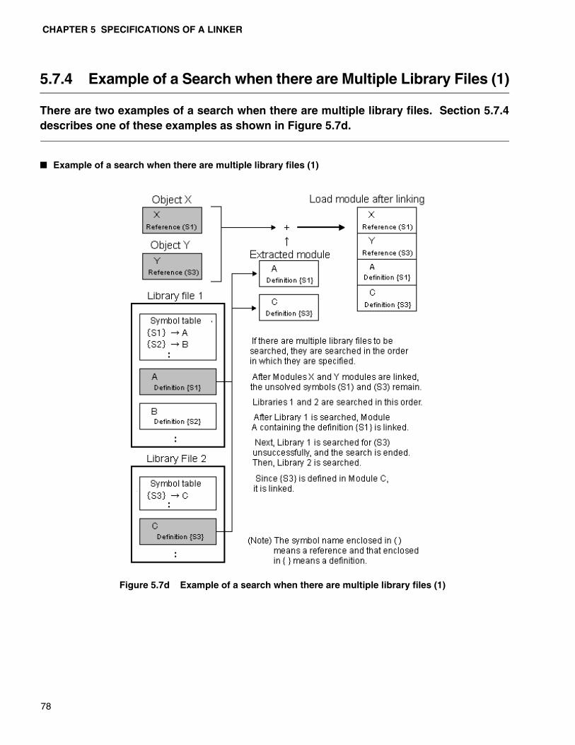
CHAPTER 5 SPECIFICATIONS OF A LINKER
78
5.7.4 Example of a Search when there are Multiple Library Files (1)
There are two examples of a search when there are multiple library files. Section 5.7.4describes one of these examples as shown in Figure 5.7d.
� Example of a search when there are multiple library files (1)
Figure 5.7d Example of a search when there are multiple library files (1)
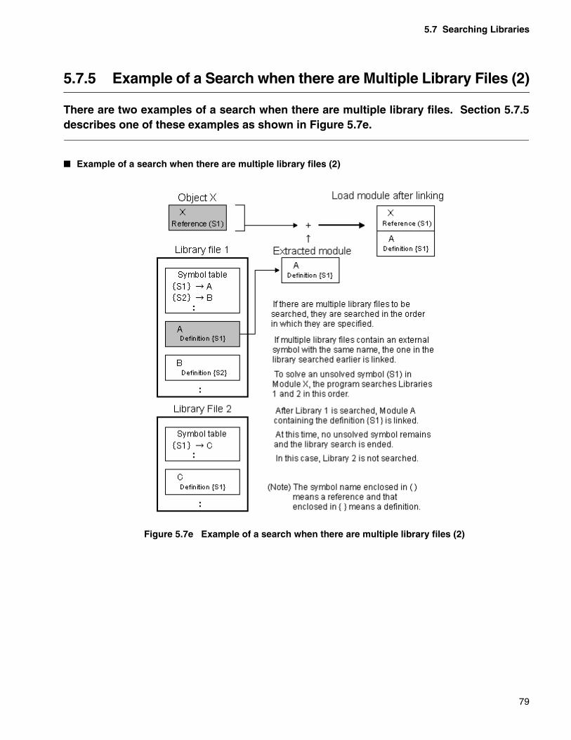
5.7 Searching Libraries
79
5.7.5 Example of a Search when there are Multiple Library Files (2)
There are two examples of a search when there are multiple library files. Section 5.7.5describes one of these examples as shown in Figure 5.7e.
� Example of a search when there are multiple library files (2)
Figure 5.7e Example of a search when there are multiple library files (2)

CHAPTER 5 SPECIFICATIONS OF A LINKER
80
5.7.6 Processing when Library Files are Individually Specified
Section 5.7.6 shows the processing when library files are individually specified asshown in Figure 5.7f.
� Processing when library files are individually specified
Figure 5.7f Processing when library files are individually specified
5.8 ROM and RAM Areas
81
5.8 ROM and RAM Areas
When you develop an application to be imported, there often are restrictions on theROM and RAM sizes and the address range that can be used.By notifying these areas to a linker at the time of linking, you may check for a sizeexceeding the limit and a section located to an unusable address.To allocate sections automatically, sections are allocated in the area specificationrange.
� ROM and RAM Areas
To have a linker locate sections, specify the section name (CODE) and the starting address at which to locate the section (0x1000) as shown in [Example 1].
[Example 1]
-sc CODE=0x1000,DATA=0x0180
Check the ending address of a section in the list map that is output as a result of linking.
Specify the starting and ending addresses at which to locate a section to have this linker check whether it is located within the specified range.
First, as shown in [Example 2], use the -ro and -ra options to determine the location address range and associate it with the area name.
[Example 2]
-ro CodeA=0x1000/0x3FFF-ra DataA=0x0180/0x57F
The area name CodeA represents the address range of 0x1000 through 0x3FFF.
The area name DataA represents the address range of 0x0180 through 0x057F.
The section location specification using an area name is as shown in [Example 3].
[Example 3]
-sc CODE=CodeA, DATA=DataA
If you specify an address name to locate a section, this program can check whether the section is located in the specified address range.
CHAPTER 5 SPECIFICATIONS OF A LINKER
82
5.9 Sections to be Transferred from ROM to RAM
When developing a program using a C compiler, a variable with an initial value iscreated and you must often rewrite the variable and perform other processing.Such a variable, being rewritten at the time of execution, must be in RAM when theapplication is executed. Therefore, in a program to be imported, the initial value datamust be placed in ROM and transferred to RAM before the application is executed.The section to be transferred from ROM to RAM is a function that enables such ausage.
� Sections to be transferred from ROM to RAM
When developing a program using a C compiler, a variable with an initial value is created and you must often rewrite the variable and perform other processing.
In a program to be imported, the variable data with initial values are placed in ROM. However, since it is being rewritten at the time of execution, it must be in RAM when the application is executed.
Therefore, the initial value data is transferred to RAM before the application is executed.
To facilitate such a usage, this linker, as long as the sections to be transferred from ROM to RAM are specified, supports the system of solving the reference addresses of a program on RAM and placing the data with initial values on ROM.
� Using the sections to be transferred from ROM to RAM
Specify the sections to be transferred from ROM to RAM in the -sc option as follows:
The sections containing variables with initial values shall be INIT.
DATA shall be the sections containing variables without initial values, start shall be a program used to transfer the data of variables with initial values on ROM to RAM, and CODE shall be the application program to be executed.
-sc DATA+INIT=0x1000,start+CODE+@INIT=0xC000
As shown in the figure, specify to locate INIT on RAM (0x1000), and also to locate INIT on ROM (xC000) using a section name starting with an at sign, @.
If the section is thus located, INIT is processed as a section to be transferred from ROM to RAM, and the location is as shown in Figure 5.9a. Then, the addresses are solved on RAM and the initial value data is located on ROM

5.9 Sections to be Transferred from ROM to RAM
83
.
Figure 5.9a Example of locating a section to be transferred from ROM to RAM
At this time, the symbols for showing the beginning of a section to be transferred from ROM to RAM are automatically generated as “_ROM_section-name” and “_RAM_section-name”. For example, as _ROM_INIT or _RAM_INIT.
You can use these symbols in the program to transfer the data of variables with initial values on ROM to RAM.
“_ROM_section-name” and “_RAM_section-name” are symbols reserved for a linker. Do not define these names in a program. For details, see Section 8.1, “Restrictions on a Linker.” For an example of a program to transfer data of variables with initial values, see Section 8.2, “Questions and Answers on Using a Linker.”
� Precautions on the sections to be transferred from ROM to RAM
Specifying the sections to be transferred from ROM to RAM changes the Write attribute of the sections unconditionally.
For the section located on ROM, the Write attribute is disabled. For the sections located on RAM, the Write attribute is enabled.
The following section is an example of sections to be transferred from ROM to RAM in a program:
DATA
0x1000
INITRAM
start
0xC000
CODEROM
(INIT)
_RAM_INIT(Transfer destination starting address symbol)
_ROM_INIT(Transfer source starting address symbol)

CHAPTER 5 SPECIFICATIONS OF A LINKER
84
.program sample
.section init, data
val1: .word 0x1234
val2: .word 0x5678
.section Data, data
val3: .res.w 0x1
.section Prog1, code
ld @val1, r2
ld @val2, r3
.section Prog2, code
ldi @val3, r13
cmp #0, r13
The above program has the init section containing variables with initial values, the Data section containing variable areas, and the Prog1 and Prog2 sections containing program code.
Table 5.9a shows for each section whether execution, read or write is enabled or disabled after assembling.
…Enabled ×…Disabled
If init and Prog1 is specified as the sections to be transferred from ROM to RAM at the time of linking, the execution, read, and write for these sections after linking is enabled or disabled as shown in Table 5.9b.
…Enabled ×…Disabled
Table 5.9a Attributes of sections after assembly
Section name Execution Read Writeinit ×
Data × Prog1 ×Prog2 ×
Table 5.9b Attributes of sections after linking
Section name Execution Read Write Remarksinit (RAM) × init (ROM) × × ROM section provided by the
linkerWrite is disabled.Data ×
Prog1(RAM) Write is enabled.Prog1(ROM) × ROM section provided by the
linkerProg2 ×
5.10 CPU Information File
85
5.10 CPU Information File
The Linker specifies the CPU from -cpu option and automatically specifies the ROM/RAM areas from the CPU information file.
� CPU Information
The Linker specifies the CPU from the -cpu option and selects the information of the appropriate chip to automatically specify the ROM/RAM areas from the CPU information file.
� ROM/RAM Areas Names
The Linker sets the following names for the ROM/RAM areas.
• ROM Areas:_ROM_*_
Numbers are entered at the asterisk (*) in order from the lower address region startingfrom 1. If there is only 1 area, the number will be ’_ROM_1_’.
• RAM Areas:_RAM_*_
Numbers are entered at the asterisk (*) in order from the lower address region startingfrom 1. If there is only 1 area, the number will be ’_RAM_1_’.These names are used by the -sc options.
� CPU Information File
The following shows the CPU information file name and the search directory.
❍ CPU Information file name
• F2MC-8L Family : 896.csv
• F2MC-16 Family : 907.csv
• FR Family : 911.csv
❍ Search Directory
• F2MC-8L Family : %FETOOL%\LIB\896
• F2MC-16 Family : %FETOOL%\LIB\907
• FR Family : %FETOOL%\LIB\911
� Specifies to prevent the internal ROM/RAM area from being set automatically
The Linker specifies the CPU from the -cpu option by default and selects the appropriate chip information from the CPU information file to automatically set the ROM/RAM areas. Specify the -Xset_rora option when you want to deter this function.
Note: If the CPU information file cannot be found, or the appropriate MB number in the CPUinformation file does not exist, the Linker will issue a error.
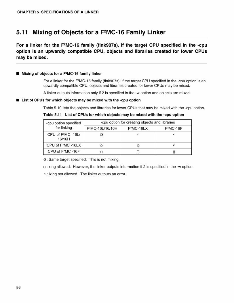
CHAPTER 5 SPECIFICATIONS OF A LINKER
86
5.11 Mixing of Objects for a F2MC-16 Family Linker
For a linker for the F2MC-16 family (flnk907s), if the target CPU specified in the -cpuoption is an upwardly compatible CPU, objects and libraries created for lower CPUsmay be mixed.
� Mixing of objects for a F2MC-16 family linker
For a linker for the F2MC-16 family (flnk907s), if the target CPU specified in the -cpu option is an upwardly compatible CPU, objects and libraries created for lower CPUs may be mixed.
A linker outputs information only if 2 is specified in the -w option and objects are mixed.
� List of CPUs for which objects may be mixed with the -cpu option
Table 5.10 lists the objects and libraries for lower CPUs that may be mixed with the -cpu option.
: Same target specified. This is not mixing.
: xing allowed. However, the linker outputs information if 2 is specified in the -w option.
× : ixing not allowed. The linker outputs an error.
Table 5.11 List of CPUs for which objects may be mixed with the -cpu option
-cpu option specified for linking
-cpu option for creating objects and librariesF²MC-16L/16/16H F²MC-16LX F²MC-16F
CPU of F²MC -16L/16/16H
× ×
CPU of F²MC -16LX ×CPU of F²MC -16F

87
CHAPTER 6 LINKER OPTIONS
This chapter explains each linker option in more detail.
6.1 List of Linker Options
6.2 Details of Linker Options
CHAPTER 6 LINKER OPTIONS
88
6.1 List of Linker Options
Options are available to specify linker operations in more detail.The following lists the option names and function outlines.
� List of linker options
For details of the parameters and functions required for the options, see the explanations of each option. For explanations of common options, see “Part 1, Chapter 3, Common Options”.
Table 6.1 List of linker options
Function Option Remarks
Input/output control options
Specification regarding output
load modules
Output load module file name specification -o DefaultOutput load module file name specification -gDebug information delete specification -Xg DefaultSpecification of outputting absolute format load module -a Default
Specification of outputting relative format load module -r
Specification regarding output
lists
Map list file name specification -m DefaultSpecification for inhibiting map list output -XmCancellation of omitting names displayed in the list -dt
Output specification of the map list file memory used information list -mmi
Specification of the number of digits in the list line -pw Default 132
Specification of the number of lines on one list page -pl Default 60
Specification regarding output
messages
Warning message output level specification-w
Allocation/link options
ROM area specification -roRAM area specification -raSection allocation -scSection group specification -grPack link specification -pk FR family
onlyRegister bank area specification -rg F²MC
family onlyAutomatic allocation specification -AL Default 0
6.1 List of Linker Options
89
Table 6.1 List of linker options (Continued)
Function Option Remarks
Library control options
Retrieval library file specification -lLibrary retrieval path specification -LLibrary specification for each symbol -elLibrary retrieval inhibit specification -nlSpecification for inhibiting default library retrieval -nd
Other link con-trol options
Entry address specification -eDummy setting external symbol values -dfTarget CPU specification -cpu need
Inhibiting Check for Presence of Debug Data -NCI0302LIB
Function that sets automatically internal ROM/RAM area
-set_rora Default
Specifies to prevent the internal ROM/RAM area from being set automatically
-Xset_rora
User-specified-area check specification -check_rora
User-specified-area check suppression specifi-cation
-Xcheck_rora Default
Section-placed-area check specification -check_locate
Section-placed-area check suppression specifi-cation
-Xcheck_locate Default
Check User-unspecified Section -check_section
Inhibit check for presence of user-unspecified section
-Xcheck_section Default
Options regard-ing the absolute format assemble
list output
Specification for relative assemble list input directory -alin
Specification for absolute assemble list output directory -alout
Specification for absolute assemble list output -alsSpecification for absolute assemble list output module -alsf
Specification for inhibiting absolute assemble list output -Xals
Specification for ROM/RAM and ARRAY list out-put -alr
Specification for ROM/RAM and ARRAY list out-put module -alrf
Specification for inhibiting ROM/RAM and ARRAY list output -Xalr
Specification for ROM/RAM and ARRAY list symbol and address display position -na/-an

CHAPTER 6 LINKER OPTIONS
90
Table 6.1 List of linker options (Continued)
Function Option Remarks
Options regarding the object content list
output
Specification for external symbol cross-refer-ence information list output -xl
Specification for external symbol cross-refer-ence information list file name -xlf
Specification for inhibiting the external symbolcrossreference information list output -Xxl
Specification for inhibiting the external symbol crossreference information list output -sl
Specification for local symbol list output -slfSpecification for local symbol list file name -XslSpecification for section detail map list output -mlSpecification for section detail map list file name -mlfSpecification for inhibiting section detail map list output -Xml
Common options
Specification for inhibiting default option file read -Xdof
Option file read specification -fHelp message display specification -helpSpecification for version number/message out-put -V
Specification for inhibiting version number/mes-sage output -XV Default
End message display specification -cmsgSpecification for inhibiting end message display -Xcmsg DefaultSpecification to set the end code to 1 when warning occurs -cwno
Specification to set the end code to 0 when warning occurs -Xcwno Default

6.2 Details of Linker Options
91
6.2 Details of Linker Options
This section explains each option of the linker. For common options in the linkage kit, see “Part 1, Chapter 3, Common Options”.
� Options related to the output module
Details of options related to the output module in “6.2.1 Output load module file name specification (-o)”- “6.2.5 Relative format load module output specification (-r)”.
� Options related to the output list
Details of options related to the output list in “6.2.6 Map list file name specification (-m)”- “6.2.11 Specification of the number of lines on one page of the list (-pl)”.
� Specification related to output messages
Details of options related to output messages in “6.2.12 Specification of the warning message output level (-w)”.
� Allocation/link options
Details of options related to the allocation/link in “6.2.13 ROM area specification (-ro)”- “6.2.19 Automatic allocation specification (-AL)”.
� Library control option
Details of options related to the library control in “6.2.20 retrieval library file specification (-l)”- “6.2.24 Default library retrieval inhibit specification (-nd)”.
� Other link control options
Details of options related to other link controls in “6.2.25 Entry address specification (-e)”- “6.2.36 Inhibit check for presence of user-unspecified section (-Xcheck_section)”.
� Options related to the absolute format assemble list output
Details of options related to the absolute format assemble list output in “6.2.37 Relative assemble list input directory specification (-alin)”- “6.2.45 ROM/RAM, ARRAY list symbol and address display position specification (-na, -an)”.
� Options related to the object content list output
Details of options related to the object content list output in “6.2.46 External symbol cross-reference information list output specification (-xl)”- “6.2.54 Section detail map list output inhibit specification (-Xsl)”.

CHAPTER 6 LINKER OPTIONS
92
6.2.1 Output Load Module File Name Specification (-o)
Specify the file name for the linked load module. If this option is not specified, theoutput file name is created from the first input file name.
� Output load module file name specification (-o)
[FORMAT]
[Parameters]
<Load module file name>
Output load module file name
[Explanation]
Specify the file name for the linked output load module.
If this option is not specified, the linker creates an output file of the name with the added extension corresponding to the link mode based on the first input file name.
If the extension is omitted when specifying a <load module file name>, a similar extension is also added depending on the link mode.
[Example 1]
flnk911s putc.obj,getc.obj
A load module file is created with the file name putc.abs.
[Example 2]
flnk911s *.obj -o outfile
A load module file is created with the file name outfile.abs.
When using the wild card to specify an input object file as shown in this example, it is recommended to specify the output file name using this option.
[Example 3]
flnk911s *.obj -o outfile.
A load module file is created with the file name outfile.
If a period is placed at the end of a file name, an extension is assumed.
[Example 4]
flnk911s *.obj -r -o outfile.rel
A load module file in the relative format is created with the file name outfile.rel.
Link mode Default extension
Absolute format output (-a option) .absRelative format output (-r option) .rel
-o < Load module file name > ( Default )
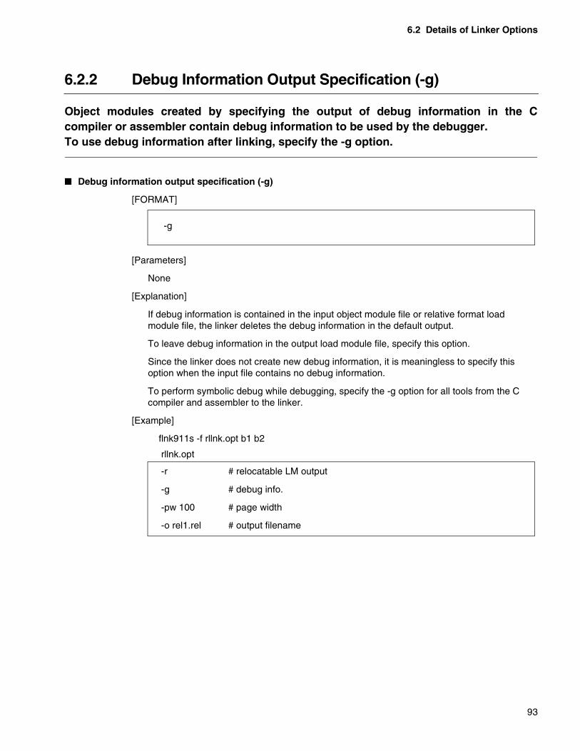
6.2 Details of Linker Options
93
6.2.2 Debug Information Output Specification (-g)
Object modules created by specifying the output of debug information in the Ccompiler or assembler contain debug information to be used by the debugger.To use debug information after linking, specify the -g option.
� Debug information output specification (-g)
[FORMAT]
[Parameters]
None
[Explanation]
If debug information is contained in the input object module file or relative format load module file, the linker deletes the debug information in the default output.
To leave debug information in the output load module file, specify this option.
Since the linker does not create new debug information, it is meaningless to specify this option when the input file contains no debug information.
To perform symbolic debug while debugging, specify the -g option for all tools from the C compiler and assembler to the linker.
[Example]
flnk911s -f rllnk.opt b1 b2
-g
rllnk.opt
-r # relocatable LM output
-g # debug info.
-pw 100 # page width
-o rel1.rel # output filename

CHAPTER 6 LINKER OPTIONS
94
6.2.3 Debug Information Delete Specification (-Xg)
Object modules that are created by specifying the output of debug information in the Ccompiler or assembler contain debug information to be used by the debugger.To remove debug information after linking, specify the -Xg option. Otherwise, do notspecify the -g option.
� Debug information delete specification (-Xg)
[FORMAT]
[Parameters]
None
[Explanation]
If debug information is contained in the input object module file or relative format load module file, the linker deletes the debug information in the default output. So there is no need to specify this option.
This option is used to cancel the -g option if, for example, the -g option is contained in the option file when linking using the option file.
[Example]
flnk911s -f rllnk.opt a1 a2 a3 -Xg -o a123.rel
- Xg ( Default )
rllnk.opt
-r # relocatable LM output
-g # debug info.
-pw 100 # page width
-o rel1.rel # output filename

6.2 Details of Linker Options
95
6.2.4 Absolute Format Load Module Output Specification (-a)
The -a option is an option to specify the creation of a load module of the absoluteformat which is the final object file of the linker.
� Absolute format load module output specification (-a)
[FORMAT]
[Parameters]
None
[Explanation]
This option specifies the load module file output in the absolute format.
Since the default output of the linker is in the absolute format, this option is normally not used. This option is used to cancel the -r specification and to enable the -a specification.
Output files of the absolute format are created with the following names.
• If the -o option is not specifiedName of the input file specified first with the extension changed to “.abs”.
• If the -o option is specifiedSpecified name. If no extension is specified, “.abs” is added to the name.
[Example]
flnk911s a1 a2 a3 -r -o a123.abs -a
The -r option in the middle of the command line is canceled.
An output load module file is created in the absolute format.
- a ( Default )
CHAPTER 6 LINKER OPTIONS
96
6.2.5 Relative Format Load Module Output Specification (-r)
The -r option is an option to specify creating a load module of the relative format thatcan be reentered. A load module of the relative format has a format that gathersmultiple modules in one file without performing address resolution.
� Relative format load module output specification (-r)
[FORMAT]
[Parameters]
None
[Explanation]
This option specifies the load module file output in the relative format.
Specify this option when changing the default output (absolute format) of the linker.
If the - r option is specified after -a, the -a option can be canceled.
A load module of the relative format has a format that gathers multiple object modules in one file without performing address resolution. A file of this format can be reentered in the linker, reducing the number of input files to be specified for the following link processing. However, if any change occurs in a module contained in the load module, it cannot be replaced with a library format file.
If this option is specified, all options related to the absolute format assemble list and object content list are ignored and their files are not output.
Output files are created with the following names.
• If the -o option is not specifiedName of the input file specified first with the extension changed to “.rel”.
• If the -o option is specifiedSpecified name. If no extension is specified, “.rel” is added to the name.
[Example]
flnk911s a1 a2 a3 -r -o a123.rel
The output object format of the linker is changed to the relative format.
Note: If the extension of the input file specified first is “.rel”, the output file name willbe the same. Since the contents of the input file are not saved in this case,specify the output file name with -o option to avoid any inconvenience.
- r
6.2 Details of Linker Options
97
6.2.6 Map List File Name Specification (-m)
This option specifies the name of the map list file to be output by the linker.If this option is not specified, a file name is created from the output load module filename.
� Map list file name specification (-m)
[FORMAT]
[Parameters]
<Map list file name>
Output map list file name
The parameters cannot be omitted.
[Explanation]
By default, the linker outputs a map list file. At this point, a file is created with the name of the output load module file whose extension is changed to “.mp1”.
The -m option is used to change the default map list file name.
If the -m option is specified after the -Xm option, the -Xm option can be canceled.
[Example]
flnk911s a1 a2 a3 -r -o a123.rel -m a123.map
The map list file name output by the linker is changed to a123.map.
-m < Map list file name > ( Default )
CHAPTER 6 LINKER OPTIONS
98
6.2.7 Map List Output Inhibit Specification (-Xm)
This option instructs the linker not to output map list files. If this option is notspecified, a map list file is always created.
� Map list output inhibit specification (-Xm)
[FORMAT]
[Parameters]
None
[Explanation]
This option inhibits output of map list files.
If the -Xm option is specified after the -m option, the -m option can be canceled.
By specifying the -Xm option, the -dt -pw, and -pl options can be canceled.
[Example]
flnk911s a1 a2 a3 -r -o a123.rel -Xm
Creating a map list file is inhibited.
- Xm

6.2 Details of Linker Options
99
6.2.8 Canceling the Omission of Names Displayed in the List (-dt)
Names such as the section names and symbol names are displayed in the map list andobject content list of the linker. By default list output, considering legibility of the lists,long names are only partially displayed.This option instructs to output the names without omission.For the display format of the map lists, see “7.2 Link List Files”.
� Canceling the omission of names displayed in the list (-dt)
[FORMAT]
[Parameters]
None
[Explanation]
Symbol names or section names displayed in the map list or object content list are displayed without omission. In such cases, one symbol name or section name is displayed in several lines.
By default, about 80 characters can be displayed. If a small number is set as the number of characters to be displayed in one line, the number of characters that can be displayed decreases accordingly. In such cases, symbol names or section names may be displayed with some parts omitted.
[Example]
flnk911s a1 a2 a3 -o a123.abs -m a123.map -dt
The symbol names and section names in use are displayed in the list without omission.
- dt
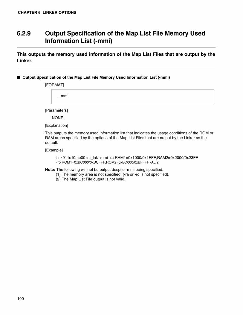
CHAPTER 6 LINKER OPTIONS
100
6.2.9 Output Specification of the Map List File Memory UsedInformation List (-mmi)
This outputs the memory used information of the Map List Files that are output by theLinker.
� Output Specification of the Map List File Memory Used Information List (-mmi)
[FORMAT]
[Parameters]
NONE
[Explanation]
This outputs the memory used information list that indicates the usage conditions of the ROM or RAM areas specified by the options of the Map List Files that are output by the Linker as the default.
[Example]
flnk911s l0mp00 im_lnk -mmi -ra RAM1=0x1000/0x1FFF,RAM2=0x2000/0x23FF-ro ROM1=0xBC000/0xBCFFF,ROM2=0xBD000/0xBFFFF -AL 2
Note: The following will not be output despite -mmi being specified.(1) The memory area is not specified. (-ra or -ro is not specified).(2) The Map List File output is not valid.
- mmi

6.2 Details of Linker Options
101
6.2.10 Specification of the Number of Digits in the List Line (-pw)
By default, up to 132 digits can be displayed in one line of the map list and objectcontent list output by the linker. This option is specified to change the number ofdigits to be displayed in one line.
� Specification of the number of digits in the list line (-pw)
[FORMAT]
[Parameters]
<Number of digits>Number of digits to be displayed in one line. Specify the number in the range of 70-1023.
[Explanation]
The length of one line of the link list file and object content list is specified.
If this value is not specified, 132 is set.
[Example]
flnk911s a1 a2 a3 -o a123.abs -m a123.map -dt -pw 80
The number of digits to be displayed in one line is set to 80.
- pw < Number of digits > (Default : 132)

CHAPTER 6 LINKER OPTIONS
102
6.2.11 Specification of the Number of Lines on one List Page (-pl)
By default, up to 60 lines are displayed on one page of the map list and object contentlist output by the linker.This option is specified to change the number of lines to be displayed on one page.
� Specification of the number of lines on one list page (-pl)
[FORMAT]
[Parameters]
<Number of lines> Number of lines to be displayed on one page.Specify 0 or in the range of 20-255.
[Explanation]
The number of lines on one page of the link list file and object content list is specified.
If this value is not specified, 60 is set.
If 0 is specified, page control is canceled.
[Example]
flnk911s a1 a2 a3 -o a123.abs -m a123.map -dt -pl 64 -pw 100
The number of lines to be displayed on one page of the list is set to 64.
- pl < Number of lines > ( Default : 60 )
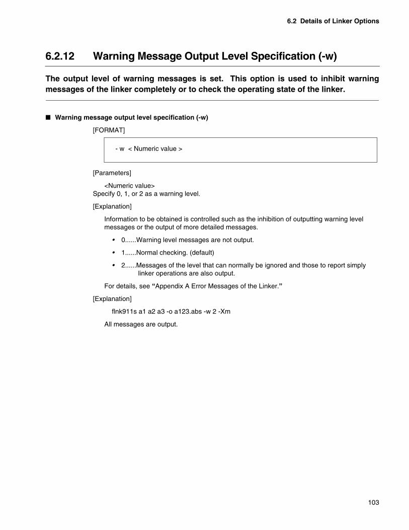
6.2 Details of Linker Options
103
6.2.12 Warning Message Output Level Specification (-w)
The output level of warning messages is set. This option is used to inhibit warningmessages of the linker completely or to check the operating state of the linker.
� Warning message output level specification (-w)
[FORMAT]
[Parameters]
<Numeric value> Specify 0, 1, or 2 as a warning level.
[Explanation]
Information to be obtained is controlled such as the inhibition of outputting warning level messages or the output of more detailed messages.
• 0......Warning level messages are not output.
• 1......Normal checking. (default)
• 2......Messages of the level that can normally be ignored and those to report simply linker operations are also output.
For details, see “Appendix A Error Messages of the Linker.”
[Explanation]
flnk911s a1 a2 a3 -o a123.abs -w 2 -Xm
All messages are output.
- w < Numeric value >
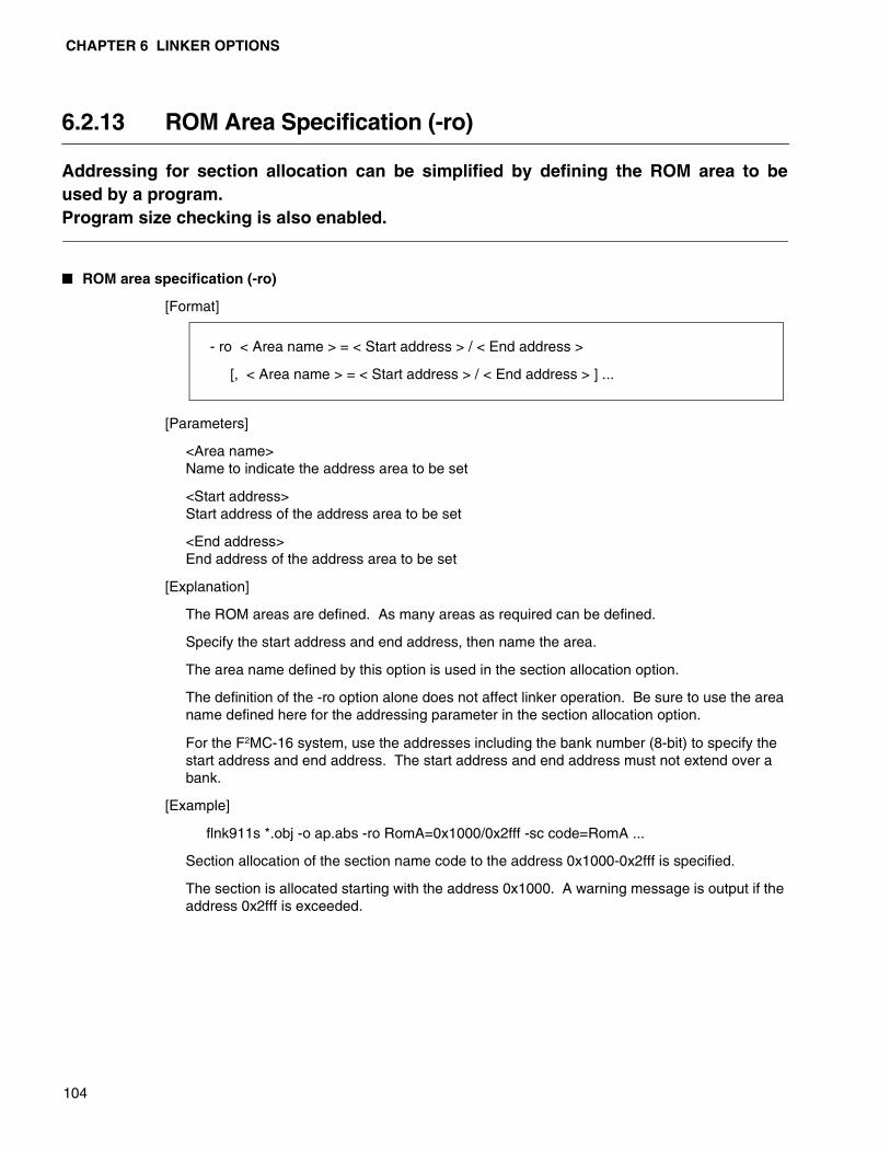
CHAPTER 6 LINKER OPTIONS
104
6.2.13 ROM Area Specification (-ro)
Addressing for section allocation can be simplified by defining the ROM area to beused by a program.Program size checking is also enabled.
� ROM area specification (-ro)
[Format]
[Parameters]
<Area name>Name to indicate the address area to be set
<Start address> Start address of the address area to be set
<End address>End address of the address area to be set
[Explanation]
The ROM areas are defined. As many areas as required can be defined.
Specify the start address and end address, then name the area.
The area name defined by this option is used in the section allocation option.
The definition of the -ro option alone does not affect linker operation. Be sure to use the area name defined here for the addressing parameter in the section allocation option.
For the F2MC-16 system, use the addresses including the bank number (8-bit) to specify the start address and end address. The start address and end address must not extend over a bank.
[Example]
flnk911s *.obj -o ap.abs -ro RomA=0x1000/0x2fff -sc code=RomA ...
Section allocation of the section name code to the address 0x1000-0x2fff is specified.
The section is allocated starting with the address 0x1000. A warning message is output if the address 0x2fff is exceeded.
- ro < Area name > = < Start address > / < End address >
[, < Area name > = < Start address > / < End address > ] ...
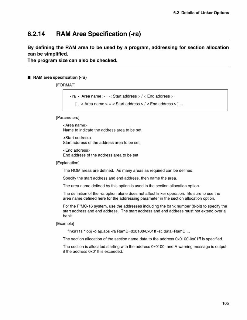
6.2 Details of Linker Options
105
6.2.14 RAM Area Specification (-ra)
By defining the RAM area to be used by a program, addressing for section allocationcan be simplified.The program size can also be checked.
� RAM area specification (-ra)
[FORMAT]
[Parameters]
<Area name>Name to indicate the address area to be set
<Start address> Start address of the address area to be set
<End address> End address of the address area to be set
[Explanation]
The ROM areas are defined. As many areas as required can be defined.
Specify the start address and end address, then name the area.
The area name defined by this option is used in the section allocation option.
The definition of the -ra option alone does not affect linker operation. Be sure to use the area name defined here for the addressing parameter in the section allocation option.
For the F2MC-16 system, use the addresses including the bank number (8-bit) to specify the start address and end address. The start address and end address must not extend over a bank.
[Example]
flnk911s *.obj -o ap.abs -ra RamD=0x0100/0x01ff -sc data=RamD ...
The section allocation of the section name data to the address 0x0100-0x01ff is specified.
The section is allocated starting with the address 0x0100, and A warning message is output if the address 0x01ff is exceeded.
- ra < Area name > = < Start address > / < End address >
[ , < Area name > = < Start address > / < End address > ] ...

CHAPTER 6 LINKER OPTIONS
106
6.2.15 Section Allocation Order/Address Specification (-sc)
This option specifies the start address and allocation order of the section allocation forthe linker.
� Section allocation order/address specification (-sc)
[Format]
[Parameters]
<Section name list> The wild card can be used to specify the section name, section group name, or list section name.
When specifying multiple names, link them with the + symbol.
<Content type> code, data, stack, const, dir, dirconst, IO
dir :only for F2MC-8L
dirconst :only for the F2MC-16 system
<Allignment> Only F2MC-16 can be specified. The boundary of the next area that can be allocated can be specified using the following keywords.
• BYTE : Allocates at the byte boundary that can be allocated. If any allocatedsegment exists, allocation is carried out without a gap.
• WORD : Allocates at the word boundary of the address that can be allocated.
• PAGE : Allocates at the page boundary of the address that can be allocated.
<Address> Start address of the allocation
<Area name> Area name specified in the ROM/RAM specification option
[Explanation]
The order of section allocation and the allocation address are specified.
The order of section allocation follows the order described in the parameters.
Allocation starts with the address 0 if the address or area name is not specified.
If the @ mark is attached to the head of a section name, the address is specified on the ROM side of the ROM -> RAM transfer section. This section operates transferring data from ROM to RAM during execution.
Use double quotation marks to indicate a wild card. Do not use double quotation marks (") in an option file.
- sc < Section name list > [ / < Content type > ] [ / < Alignment > ]
[ = { < Address > | < Area name > } ] [ , ... ]

6.2 Details of Linker Options
107
[Example 1]
flnk911s *.obj -o ap.abs -sc "*/code"=0xC1000,D=0x1000 ...
Figure 6.2.14b shows the allocation example in this case.
The section whose content type is code is allocated starting with the address 0xC1000 and section D is allocated starting with the address 0x1000.
Figure 6.2a Section allocation example 1
[Example 2]
flnk911s *.obj -o ap.abs -ro ROM=0xC1000/0xCFFFF -ra RAM=0x1000/0x13FF -scP+code+text1=ROM,D=RAM
Figure 6.2b shows the allocation example in this case.
If section allocation is specified using the ROM/RAM option, the allocation end address can be checked.
Figure 6.2b Section allocation example 1
D
0x1000
Sections whosecontent type is code
0xC1000
D0x1000
0xC1000
0x13FF
P
code
text10xCFFFF

CHAPTER 6 LINKER OPTIONS
108
The wild card character that can be used in the <section name list> is only '*' and the following four description patterns are available.
Note: Sections agreeing with the wild card specifying do not include sections specified by othersc options or absolute addresses (sections arrangement attributes that are ABS). -sc *=RAM -sc CODE=RAMAll wild card specifying, in specifying like the one above, agree with sections other than the’CODE’ that can be rearranged (sections arrangement attributes that are REL).
Pattern Example Explanation
* -sc “*/code” Match with all sections whose content Match ab_1, code_1, XXsect, etc type is codeMismatch None
_* -sc “ab_*/code” Match with all sections whose content Match ab_1, ab_XX, ab_, etc type is code and whose first three Mismatch aab_XX, ab, etc characters are “ab_”
*_ -sc “*_1/code” Match with all sections whose content Match ab_1, XX_1, _1, etc type is code and whoselast two last Mismatch ab_11, _, etc two characters are “_1”
_*_ -sc “ab_*_1/code” Match with all sections whose content Match ab_XX, ab_1, etc type is code, whose first three characMismatch aab_XX_11, ab_1, etc ters are “ab_”, and whose last two
characters are “_1”
6.2 Details of Linker Options
109
6.2.16 Section Group Specification (-gr)
Multiple sections are linked to create a group according to the purpose of the user anda group name is given to the group.By using this group name when specifying the section allocation, multiple sections canbe handled as one group.
� Section group specification (-gr)
[Format]
[Parameters]
<Group name>
Generic name of multiple sections to be grouped
<Section name list>
Describes section names to be grouped.
The wild card can be used.
When specifying multiple names, link them with the + symbol.
<Content type>
code, data, stack, const, dir, dirconst, IO
dir :only for F2MC-8L
dirconst :only for the F2MC-16 system
[Explanation]
Sections to be grouped and the order of allocation of sections in the group are specified.
The order of section allocation follows the order described in the parameters.
Each group name must be a unique name which does not overlap with the section names and other group names.
A section that belongs to one group must not belong to another group.
When using the wild card, indicate it using double quotation marks. Do not use double quotation marks (“ ) in an option file.
[Example 1]
flnk911s *.obj -o ap.abs -ro ROM=0xC1000/0xCffff -ra RAM=0x1000/0x13ff ...-gr romG=P+code+text1 -sc romG=ROM,D=RAM ...
When using the grouping option, the whole group can be represented by its group name instead of specifying any number of section names.
[Example 2]
flnk911s *.obj -o ap.abs -gr cdgrp=”*/code” -sc cdgrp=0xC1000
All sections whose content type is code are linked to a group and the group name cdgrp is given to the group. Then the group is allocated to the address 0xC1000 using the -sc option.
- gr < Group name > = < Section name list > [ / < Content type > ] [ , ... ]

CHAPTER 6 LINKER OPTIONS
110
6.2.17 Pack Link Specification (-pk)
The alignment specification (boundary adjustment) of allocation information ofsections is canceled, then sections are linked and allocated with 1-byte boundary.Application programs may not be executed correctly. Sufficient care must be takenwhen using this option.This option is supported only for the FR family.
� Pack link specification (-pk)
[Format]
[Parameters]
<Section name>Specify the section name to be pack linked.
[Explanation]
The alignment specification (boundary adjustment) of allocation information of sections is canceled and then sections are linked (with 1-byte boundary) .
This option is supported only for the FR family.
Be careful when specifying -pk. By specifying this option, program operations may be slower or programs may become inoperable.
The -pk option is not intended for alignment of structured members.
[Example]
flnk911s *.obj -o ap.abs -pk code ...
- pk < Section name >

MEMO
111
CHAPTER 6 LINKER OPTIONS
112
6.2.18 Register Bank Area Specification (-rg)
The register bank area used by programs is specified. This option is supported only for the F2MC family.
� Register bank area specification (-rg)
[Format]
[Parameters]
<Register bank number>Specify the register bank number to be set.
[Explanation]
The register bank area used by programs is specified.
When using general registers in a program, areas must be reserved using this option.
When specifying the consecutive register bank numbers, it is possible to specify them using a hyphen, for example, “3-8”. (In this case, specify the register banks 3, 4, 5, 6, 7, and 8)
If this option is not specified, the linker does not reserve any register bank area.
This option is valid only for the F2MC-8L family/F2MC-16 family.
Table 6.2 shows the areas reserved by the -rg option.
-rg < Register bank number >
[ {, < Register bank number > |- < Register bank number > } ] ...
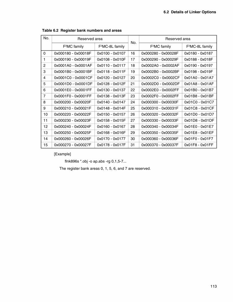
6.2 Details of Linker Options
113
[Example]
flnk896s *.obj -o ap.abs -rg 0,1,5-7...
The register bank areas 0, 1, 5, 6, and 7 are reserved.
Table 6.2 Register bank numbers and areas
No. Reserved areaNo.
Reserved area
F2MC family F2MC-8L family F2MC family F2MC-8L family
0 0x000180 - 0x00018F 0x0100 - 0x0107 16 0x000280 - 0x00028F 0x0180 - 0x0187
1 0x000190 - 0x00019F 0x0108 - 0x010F 17 0x000290 - 0x00029F 0x0188 - 0x018F
2 0x0001A0 - 0x0001AF 0x0110 - 0x0117 18 0x0002A0 - 0x0002AF 0x0190 - 0x0197
3 0x0001B0 - 0x0001BF 0x0118 - 0x011F 19 0x0002B0 - 0x0002BF 0x0198 - 0x019F
4 0x0001C0 - 0x0001CF 0x0120 - 0x0127 20 0x0002C0 - 0x0002CF 0x01A0 - 0x01A7
5 0x0001D0 - 0x0001DF 0x0128 - 0x012F 21 0x0002D0 - 0x0002DF 0x01A8 - 0x01AF
6 0x0001E0 - 0x0001FF 0x0130 - 0x0137 22 0x0002E0 - 0x0002FF 0x01B0 - 0x01B7
7 0x0001F0 - 0x0001FF 0x0138 - 0x013F 23 0x0002F0 - 0x0002FF 0x01B8 - 0x01BF
8 0x000200 - 0x00020F 0x0140 - 0x0147 24 0x000300 - 0x00030F 0x01C0 - 0x01C7
9 0x000210 - 0x00021F 0x0148 - 0x014F 25 0x000310 - 0x00031F 0x01C8 - 0x01CF
10 0x000220 - 0x00022F 0x0150 - 0x0157 26 0x000320 - 0x00032F 0x01D0 - 0x01D7
11 0x000230 - 0x00023F 0x0158 - 0x015F 27 0x000330 - 0x00033F 0x01D8 - 0x01DF
12 0x000240 - 0x00024F 0x0160 - 0x0167 28 0x000340 - 0x00034F 0x01E0 - 0x01E7
13 0x000250 - 0x00025F 0x0168 - 0x016F 29 0x000350 - 0x00035F 0x01E8 - 0x01EF
14 0x000260 - 0x00026F 0x0170 - 0x0177 30 0x000360 - 0x00036F 0x01F0 - 0x01F7
15 0x000270 - 0x00027F 0x0178 - 0x017F 31 0x000370 - 0x00037F 0x01F8 - 0x01FF

CHAPTER 6 LINKER OPTIONS
114
6.2.19 Automatic Allocation Specification (-AL)
Automatic allocation of sections is specified.
� Automatic allocation specification (-AL)
[Format]
[Parameters]
<0> No automatic allocation (default)
<1>If an absolute section exists in the area, the order of allocation is changed appropriately to avoid overlapping with the section.
<2>Whether to allocate to the ROM area or RAM area is determined based on the section attributes. Then allocation is carried out to free space of each area.
(link907a automatic allocation compatible)
[Explanation]
Automatic allocation of sections is specified.
• If the parameter is 1If an absolute section exists when allocating sections to the areas specified by the -raor -ro option, relocatable sections are allocated in such a way that allocation addressesdo not overlap. In such cases, sections are allocated in descending order of thealignment value and size starting with the section of the largest alignment value andsize. In this way, optimal allocation is implemented where free space is minimum.
• If the parameter is 2Whether to allocate sections whose allocation is not specified by the -sc option to theROM area or RAM area is determined based on the section attributes. Then suchsections are allocated to free space of each area.
See also “5.6 Automatic Allocation of Sections”.
[Example]
flnk911s -AL 1 -ro ROM=0x1000/0x1FFF -sc code1+code2+code3=ROM …
Each section is given as follows.
• code1 : relocatable, size=0x18
• code2 : relocatable, size =0z10
• code3 : relocatable, size =0z30
• AbsSec : absolute, address range=0x1010-0x1017
The following figure shows the link map for this case.
- AL { 0 | 1 | 2 }
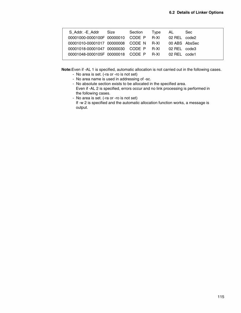
6.2 Details of Linker Options
115
Note:Even if -AL 1 is specified, automatic allocation is not carried out in the following cases. - No area is set. (-ra or -ro is not set)- No area name is used in addressing of -sc.- No absolute section exists to be allocated in the specified area. Even if -AL 2 is specified, errors occur and no link processing is performed in the following cases.- No area is set. (-ra or -ro is not set) If -w 2 is specified and the automatic allocation function works, a message is output.
S_Addr. -E_Addr Size Section Type AL Sec00001000-0000100F 00000010 CODE P R-XI 02 REL code200001010-00001017 00000008 CODE N R-XI 00 ABS AbsSec00001018-00001047 00000030 CODE P R-XI 02 REL code300001048-0000105F 00000018 CODE P R-XI 02 REL code1
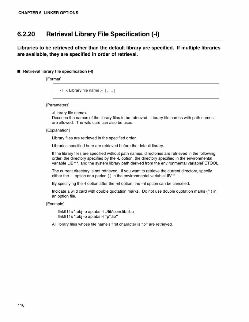
CHAPTER 6 LINKER OPTIONS
116
6.2.20 Retrieval Library File Specification (-l)
Libraries to be retrieved other than the default library are specified. If multiple librariesare available, they are specified in order of retrieval.
� Retrieval library file specification (-l)
[Format]
[Parameters]
<Library file name>Describe the names of the library files to be retrieved. Library file names with path names are allowed. The wild card can also be used.
[Explanation]
Library files are retrieved in the specified order.
Libraries specified here are retrieved before the default library.
If the library files are specified without path names, directories are retrieved in the following order: the directory specified by the -L option, the directory specified in the environmental variable LIB***, and the system library path derived from the environmental variableFETOOL.
The current directory is not retrieved. If you want to retrieve the current directory, specify either the -L option or a period (.) in the environmental variableLIB***.
By specifying the -l option after the -nl option, the -nl option can be canceled.
Indicate a wild card with double quotation marks. Do not use double quotation marks (“ ) in an option file.
[Example]
flnk911s *.obj -o ap.abs -l ..\lib\com.lib,libuflnk911s *.obj -o ap.abs -l “p*.lib”
All library files whose file name's first character is “p” are retrieved.
- l < Library file name > [ , ... ]

6.2 Details of Linker Options
117
6.2.21 Library Retrieval Path Specification (-L)
The path name for retrieving the library file is specified.
� Library retrieval path specification (-L)
[Format]
[Parameters]
<Library path name>Name of the path storing the library file
[Explanation]
In which directory the library file specified by the -l option exists is instructed for the linker.
Normally, specify the environmental variableLIB*** so that this option need not be specified.
The C libraries attached to the C compiler are stored in the path specified by LIB***. To manage libraries created specially by the user, use the -L option to manage them in another directory.
If multiple paths are specified, they are retrieved in order of specification.
The library file is first retrieved in the path specified here, then in the environmental variable LIB*** and system library path derived from the environmental variable FETOOL.
If a library path is specified with its path name, only the specified path is retrieved.
If the -nl option exists, library retrieval is not performed, thus the -L option is canceled.
[Example]
flnk911s *.obj -o ap.abs -L C:\usr\usrlib -l com.lib,libu
- L < Library path name > [ , ... ]

CHAPTER 6 LINKER OPTIONS
118
6.2.22 Library Specification for Each Symbol (-el)
The library file to be used for the resolution of external reference symbols can bespecified.
� Library specification for each symbol (-el)
[Format]
[Parameters]
<Symbol name list>Describe the external reference symbol names.When specifying multiple symbols, separate them with /.
<Library file name>Library file name to be retrieved.Library file names with path names can also be specified. The wild card_ cannot be used.
[Explanation]
The library file to be used for the resolution of the external reference symbol value specified in this option is specified.
This option is used when a module containing the same external definition symbol name exists in multiple libraries and the linker links undesirable modules in the standard library retrieval order.
Libraries are not often created appropriately so it is inevitable that this function will be applied when using multiple libraries. However, since using this function may cause unexpected problems.
Examine whether library files can be recreated.
The retrieval directories when a library file name is specified without its path name are the same as those for the -l option.
[Example]
flnk911s *.obj -o sp.abs -L C:\usr\usrlib -l libu,sublib -el sym1=sublib
- el < Symbol name list > = < Library file name > [ , ... ]
6.2 Details of Linker Options
119
6.2.23 Library Retrieval Inhibit Specification (-nl)
The inhibition of the library file retrieval is instructed.
� Library retrieval inhibit specification (-nl)
[Format]
[Parameters]
None
[Explanation]
The inhibition of the library file retrieval is specified.
[Example 1]
flnk911s -L C:\usr\usrlib -l libu,sublib *.obj -o ap.abs -nl
The -L, -l, and -el options previously specified are canceled and library retrieval including the default library is inhibited.
[Example 2]
flnk911s -l libl *.obj -o ap.abs -nl -l lib2
lib1.lib specified once is canceled and retrieval of lib2.lib is instructed.
As shown in this example, if the -nl option is specified between multiple, -l options specified before -nl are all canceled. However, the -L option specification, -el option specification, -nd option specification, and default library retrieval are restored to the settings before the -nl specification.
Thus, in this example, lib2.lib and the default library are retrieved.
- nl
CHAPTER 6 LINKER OPTIONS
120
6.2.24 Default Library Retrieval Inhibit Specification (-nd)
The default library is a library presumed to be used by the C compiler and its library filenames are set in the object file.This option instructs not to retrieve the default library.
� Default library retrieval inhibit specification (-nd)
[Format]
[Parameters]
None
[Explanation]
The specification of the default library is canceled, therefore, it is not retrieved.
[Example]
flnk911s -L C:\usr\usrlib -l libu,sublib *.obj -o ap.abs -nd
Only the libraries specified by the -l option are retrieved and the default library is not retrieved.
- nd

6.2 Details of Linker Options
121
6.2.25 Entry Address Specification (-e)
The start address of a user program is specified using an external definition symbol.
� Entry address specification (-e)
[Format]
[Parameters]
<Symbol name>Symbol name of the entry point
Only external definition symbols can be used.
[Explanation]
The start address of a user program is changed to that specified by the external definition symbol.
The start address can be specified using the .end pseudo-instruction of the assembler.
The entry point is set as the initial value of the PC (program counter) when starting execution of the simulator debugger.
[Example]
flnk911s *.obj -o ap.abs -e ProgStart
- e < Symbol name >

CHAPTER 6 LINKER OPTIONS
122
6.2.26 Dummy Setting of External Symbol Values (-df)
Undefined symbol values of a user program are forced to be defined.
� Dummy setting of external symbol values (-df)
[Format]
[Parameters]
<Symbol name> Symbol name of an external reference symbol
<Numeric value> Value to be defined
<External definition symbol name> External symbol name whose value is defined
[Explanation]
Values of undefined external reference symbols are forced to be defined.
The linker creates object data using this value for the resolution of relocation. Symbol information in the absolute format load module file to be output is not affected.
If loaded using a debugger, the symbol name specified here remains undefined.
[Example]
flnk911s -L \usr\usrlib -l libu,sublib *.obj -o ap.abs -df Sym1=100
If Sym1 is not defined, 100 is set as its value.
- df < Symbol name > = { < Numeric value > | < External definition symbol name > }

6.2 Details of Linker Options
123
6.2.27 Target CPU Specification (-cpu)
The target CPU is specified.The target CPU of programs to be linked is specified using the MB number.
� Target CPU specification (-cpu)
[Format]
External definition symbol name
[Parameters]
<MB number> MB number of the target CPU
[Explanation]
The target CPU of programs to be linked is specified using the MB number.
[Example]
flnk907s *.obj -o ap.abs -cpu MB90600A
flnk907s *.obj -o ap.abs -cpu MB90700
Note:When executing link processing, the target CPU must be specified using thisoption.
- cpu < MB number>name >
CHAPTER 6 LINKER OPTIONS
124
6.2.28 Inhibiting Check for Presence of Debug Data(-NCI0302LIB)
This option inhibits check for presence of debug data in the module extracted from thelibrary file.
� Inhibiting Check for Presence of Debug Data (-NCI0302LIB)
[Format]
[Parameters]
NONE
[Explanation]
When debug data output (-g) and warning level 2 (-w2) are specified to operate the linker, the linker outputs the following data message to the module that has no debug data.
I0302L: Debug information not exist (file name)
When this option is specified, the linker does not output the above information message to the module extracted from the library file.
[Example]
flnk907s *.obj -o ap.abs -cpu MB90704 -NCI0302LIB
flnk911s *.obj -o ap.abs -cpu MB91110 -NCI0302LIB
- NCI0302LIB

6.2 Details of Linker Options
125
6.2.29 Function that sets automatically internal ROM/RAM area(-set_rora)
Refers to CPU information file to set the information regarding the internal ROM/RAMarea of the targeted CPU.
� Function that sets automatically internal ROM/RAM area (-set_rora)
[Format]
[Parameters]
NONE
[Explanation]
Refers to CPU information file to set the information regarding the internal ROM/RAM area of the targeted CPU.
The linker, when this option is specified, refers to CPU information file and sets automatically the internal ROM/RAM area of the appropriate CPU.
The Linker sets the following names for the ROM/RAM areas.
• ROM Areas:_ROM_*_
Numbers are entered at the asterisk (*) in order from the lower address region startingfrom 1. If there is only 1 area, the number will be ’_ROM_1_’.
• RAM Areas:_RAM_*_
Numbers are entered at the asterisk (*) in order from the lower address region startingfrom 1. If there is only 1 area, the number will be ’_RAM_1_’.
These names are used by the -sc options.
[Example]
flnk911s *.obj -o ap.abs -cpu MB91110 -set_rora
flnk907s *.obj -o ap.abs -cpu MB90704 -set_rora
flnk896s *.obj -o ap.abs -cpu MB89121 -set_rora
- set_rora
CHAPTER 6 LINKER OPTIONS
126
6.2.30 Specifies to prevent the internal ROM/RAM area from being set automatically (-Xset_rora)
Prevents the information from being set regarding the internal ROM/RAM area of thetargeted CPU that is referenced to the CPU information file.
� Specifies to prevent the internal ROM/RAM area from being set automatically (-Xset_rora)
[Format]
[Parameters]
NONE
[Explanation]
Prevents the information from being set regarding the internal ROM/RAM area of the targeted CPU that is referenced to the CPU information file.
[Example]
flnk911s *.obj -o ap.abs -cpu MB91110 -Xset_rora
flnk907s *.obj -o ap.abs -cpu MB90704 -Xset_rora
flnk896s *.obj -o ap.abs -cpu MB89121 -Xset_rora
- Xset_rora

6.2 Details of Linker Options
127
6.2.31 User-specified-area check specification(-check_rora)
This When the -check_rora option is previously specified, you can check whether thememory map has been changed, by changing only the specified MB number.The -check_rora option checks whether the specified ROM and RAM areas (-ro and -raoptions) correspond to the actual addresses of the internal ROM and internal RAM.Use this option when single-chip mode is used.
� User-specified-area check specification (-check_rora)
[Format]
[Parameters]
NONE
[Explanation]
A check is made on whether the specified ROM and RAM areas (-ro and -ra options) exceed the internal ROM and internal RAM.The following warnings are output when the areas specified for the -ro and -ra options are not within the internal ROM and internal RAM:
W1368L: The area specified for the -ro option is outside the internal-ROM area (area name)
W1369L: The area specified for the -ra option is outside the internal-RAM area (area name)
When the -check_rora option is specified in using single-chip mode, a check is made on whether the specified ROM and RAM areas correspond to the actual addresses of the internal ROM and internal RAM of the product concerned. So, for instance, when a program is ported to a different product, you can check whether the memory map has been changed, by changing only the specified MB number.
Also, when the -check_locate option is specified together with the -check_rora option, you can check whether the program is within the internal ROM and internal RAM.
- check_rora

CHAPTER 6 LINKER OPTIONS
128
[Example]
flnk911s -cpu MB91F155 -check_rora -ro ROM = 0x00080800/0x000fffff -ra RAM1=0x00001000/0x00008fff, RAM2=0x00080000/0x000807ff ...
-> The areas specified for the -ro and -ra options are within the ranges of the internalROM and internal RAM; so no warning is output.
flnk911s -cpu MB91154 -check_rora -ro ROM = 0x00080800/0x000fffff -ra RAM1=0x00001000/0x00008fff, RAM2=0x00080000/0x000807ff ...
W1368L: The area specified for the -ro option is outside the internal-ROM area (ROM)
W1369L: The area specified for the -ra option is outside the internal-RAM area (RAM)
-> The underlined areas specified are not within the ranges of the internal ROM andinternal RAM; so the warnings are output.
flnk911s -cpu MB91154 -check_rora -ro ROM = 0x000A0000/0x000fffff -ra RAM1=0x00001000/0x00005fff, RAM2=0x00080000/0x000807ff ...
-> The areas specified for the -ro and -ra options are within the ranges of the internalROM and internal RAM; so no warning is output.
Note: 1. Specify the correct MB number for the -cpu option.2. A warning is output when the -check_rora option is specified even if warning outputsuppression (-w 0) is specified.3. The -check_rora option is only valid when creating absolute format load modules.The -check_rora option is ignored when creating relocatable load modules.4. The -check_rora option uses internal-ROM data and internal-RAM data contained in theCPU data file. So, no warning is output when the CPU data file contains no dataconcerned.
6.2 Details of Linker Options
129
6.2.32 User-specified-area check suppression specification(-Xcheck_rora)
The -Xcheck_rora option suppresses the check on the specified ROM area and thespecified RAM area (-ro and -ra options) and on the internal-ROM area and the internal-RAM area.Use the -Xcheck_rora option when you want to cancel the -check_rora option.
� User-specified-area check suppression specification (-Xcheck_rora)
[Format]
[Parameters]
NONE
[Explanation]
The -Xcheck_rora option suppresses the check on the specified ROM area and the specified RAM area (-ro and -ra options) and on the addresses of the internal ROM and the internal RAM.
Use the -Xcheck_rora option when you want to cancel the -check_rora option.
[Example]
flnk911s -cpu MB91154 -check_rora -ro ROM = 0x00080800/0x000fffff-ra RAM1=0x00001000/0x00008fff, RAM2=0x00080000/0x000807ff ...
W1368L: The area specified for the -ro option is outside the internal-ROM area (ROM)
W1369L: The area specified for the -ra option is outside the internal-RAM area (RAM)
-> The underlined areas specified are not within the ranges of the internal ROM andinternal RAM; so the warnings are output.
flnk911s -cpu MB91154 -check_rora -Xcheck_rora -ro ROM = 0x00080800/0x000fffff-ra RAM1=0x00001000/0x00008fff, RAM2=0x00080000/0x000807ff ...
-> Although the underlined areas specified are not within the ranges of the internal ROMand internal RAM, no warning is output because the check is suppressed using the -Xcheck_rora option.
- Xcheck_rora
CHAPTER 6 LINKER OPTIONS
130
6.2.33 Section-placed-area check specification (-check_locate)
A check is made to see that no section is specified outside the memory area.The -check_locate option checks the section-placed address, based on the specifiedROM area and the specified RAM area (-ro and -ra options) or based on the CPU datafile fs internal ROM data and internal RAM data; and outputs a warning if a section isspecified outside the memory area.
� Section-placed-area check specification (-check_locate)
[Format]
[Parameters]
NONE
[Explanation]
The -check_locate option checks the section-placed address, based on the specified ROM area and the specified RAM area (-ro and -ra options) or based on the CPU data file fs internal ROM data and internal RAM data; and outputs a warning if a section is specified outside the memory area.
W1370L: The section is placed outside the ROM area (section name)
W1371L: The section is placed outside the RAM area (section name)
W1372L: The section is placed outside the RAM area or the I/O area (section name)
W1373L: The section is placed outside the I/O area (section name)
The section types and the check areas are shown below.
- check_locate
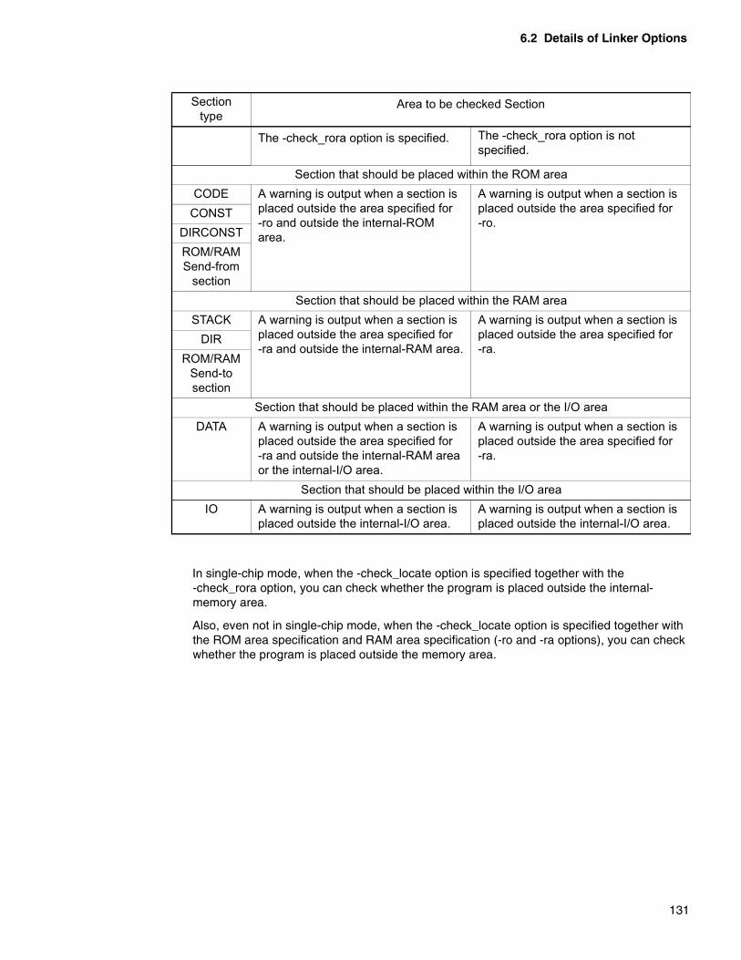
6.2 Details of Linker Options
131
In single-chip mode, when the -check_locate option is specified together with the -check_rora option, you can check whether the program is placed outside the internal-memory area.
Also, even not in single-chip mode, when the -check_locate option is specified together with the ROM area specification and RAM area specification (-ro and -ra options), you can check whether the program is placed outside the memory area.
Section type
Area to be checked Section
The -check_rora option is specified. The -check_rora option is notspecified.
Section that should be placed within the ROM areaCODE A warning is output when a section is
placed outside the area specified for -ro and outside the internal-ROM area.
A warning is output when a section is placed outside the area specified for -ro.
CONSTDIRCONSTROM/RAM Send-from
sectionSection that should be placed within the RAM area
STACK A warning is output when a section is placed outside the area specified for -ra and outside the internal-RAM area.
A warning is output when a section is placed outside the area specified for -ra.
DIRROM/RAM
Send-to section
Section that should be placed within the RAM area or the I/O areaDATA A warning is output when a section is
placed outside the area specified for -ra and outside the internal-RAM area or the internal-I/O area.
A warning is output when a section is placed outside the area specified for -ra.
Section that should be placed within the I/O areaIO A warning is output when a section is
placed outside the internal-I/O area.A warning is output when a section is placed outside the internal-I/O area.
CHAPTER 6 LINKER OPTIONS
132
[Example]
When DATA_A, DATA_B, DATA_C (these are of section type DATA), CODE_D,CODE_E, CODE_F (these are of section type CODE), and STACK_G (this is of sectiontype STACK) are placed in the following memory map, the following check will be made:
flnk911s -cpu MB91154 -check_locate -ro ROM = 0x000A0000/0x000fffff -ra RAM1=0x00001000/0x00005fff, RAM2=0x00080000/0x000807ff ...
W1372L: The section is placed outside the ROM area or the I/O area (DATA_A).
W1371L: The section is placed outside the RAM area (STACK_G).
W1372L: The section is placed outside the ROM area or the I/O area (DATA_C).
W1370L: The section is placed outside the ROM area (CODE_D).
W1370L: The section is placed outside the ROM area (CODE_F).
DATA_A is placed within the internal-I/O area; so no warning is output.
DATA_B is placed within the area specified for -ra; so no warning is output.
DATA_C is placed outside the area specified for -ra; so the warning is output.
CODE_D is placed outside the area specified for -ro; so the warning is output.
I/O
Accessinhibited
RAM1 InternalRAM (20K)
Accessinhibited
RAM2 InternalRAM (2K)
Accessinhibited
ROM InternalROM (384K)
Accessinhibited
0x00000000
0x00080800
0x00080000
0x00006000
0x00001000
0x00000800
0x00100000
0x000A0000
0xffffffff
DATA_A
CODE_E
CODE_F
DATA_C
CODE_D
STACK_G
DATA_B
6.2 Details of Linker Options
133
CODE_E is placed within the area specified for -ro; so no warning is output.
CODE_F is placed outside the area specified for -ro; so the warning is output.
STACK_G is placed outside the area specified for -ra; so the warning is output.
Note:1. A warning is output when the -check_locate option is specified even if warning outputsuppression (-w 0) is specified.2. The -check_locate option is only valid when creating absolute format load modules.The -check_locate option is ignored when creating relocatable load modules.3. When using the -check_locate option, you must specify the areas for the -ro and -raoptions in advance.4. The -check_locate option also checks ABS-attribute sections not to be processed by thelinker.

CHAPTER 6 LINKER OPTIONS
134
6.2.34 Section-placed-area check suppression specification(-Xcheck_locate)
The -Xcheck_locate option suppresses the section-placed-area check. Use the -Xcheck_locate option when you want to cancel the -check_locate option.
� Section-placed-area check suppression specification (-Xcheck_locate)
[Format]
[Parameters]
NONE
[Explanation]
The -Xcheck_locate option suppresses the section-placed-area check.
Use the -Xcheck_locate option when you want to cancel the -check_locate option.
- Xcheck_locate
6.2 Details of Linker Options
135
6.2.35 Check User-unspecified Section (-check_section)
Check for the presence of a section for which the user does not specify layout.
� Check User-unspecified Section (-check_section)
[Format]
[Parameters]
NONE
[Explanation]
Check for the presence of a section for which the user does not specify layout.
If this option is specified, the linker will output the following warning against the section not specified in the specify section layout (-sc) option.
W1375L: This is the section (section name) for which layout is not specified in the -sc option.
If this option is not specified, the linker makes no check.
[Example]
The following operation is performed when the objects having the CODE, INIT, CONST, DATA and STACK sections are linked.
flnk911s -cpu MB91154 -check_section
-ro ROM=0x000a0000/0x000fffff
-ra RAM1=0x00001000/0x00008fff,RAM2=0x00080000/0x000807ff
-sc CODE+CONST=ROM -sc DATA=RAM1 -sc STACK=RAM2 object1 object2...
W1375L: This is the section (INIT) for which layout is not specified in the -sc option.
->Layout is not specified for the INIT section.
Since the -check_section option is specified, the warning is output to the INIT section.
flnk911s -cpu MB91154 -check_section
-ro ROM=0x000a0000/0x000fffff
-ra RAM1=0x00001000/0x00008fff,RAM2=0x00080000/0x000807ff
-gr ROMGROUP=CODE+CONST -sc DATA=RAM1
-sc STACK=RAM2 object1 object2...
W1375L: This is the section (CODE) for which layout is not specified in the -sc option.
W1375L: This is the section (INIT) for which layout is not specified in the -sc option.
- check_section
CHAPTER 6 LINKER OPTIONS
136
W1375L: This is the section (CONST) for which layout is not specified in the -sc option.
->The CODE and CONST sections are grouped in the -gr option.
Since layout is not specified for these sections in the -sc option, however, the warning is output to these sections.
flnk911s -cpu MB91154 -check_section
-ro ROM=0x000a0000/0x000fffff
-ra RAM1=0x00001000/0x00008fff,RAM2=0x00080000/0x000807ff
-sc *=ROM -sc DATA=RAM1 -sc STACK=RAM2 object1 object2...
->Since the section name is specified by the wildcards, layout is specified for all the sections except the DATA and STACK sections.
Since layout is specified for all the sections, no warning is output.
[Notes]
1. No check is made on the sections for which the layout address is specified in the
source program.
2. If layout is not specified for the sections in the -sc option even when section group
is specified in the -gr option, the warning is output.
3. If the wildcards are used to specify the section name in the -sc option, layout is
specified for all the sections that match the wildcards.
Therefore, no warning is output to the sections that match the wildcards.
Take care when using the wildcards to specify the section name.
6.2 Details of Linker Options
137
6.2.36 Inhibit check for presence of user-unspecified section (-Xcheck_section)
Inhibit the check for the presence of a section for which the user does not specifylayout. This option is used to cancel the -check_section option.
� Inhibit check for presence of user-unspecified section (-Xcheck_section)
[Format]
[Parameters]
NONE
[Explanation]
Inhibit the check for the presence of a section for which the user does not specify layout. This option is used to cancel the -check_section option.
This option is default.
[Example]
The following operation is performed when the objects having the CODE, INIT, CONST, DATA and STACK sections are linked.
flnk911s -cpu MB91154 -check_section -Xcheck_section
-ro ROM=0x000a0000/0x000fffff
-ra RAM1=0x00001000/0x00008fff,RAM2=0x00080000/0x000807ff
-sc CODE+CONST=ROM -sc DATA=RAM1 -sc STACK=RAM2 object1 object2 ...
->Layout is not specified for the INIT section.
Since the check is inhibited in the Xcheck_section option, no warning is output.
flnk911s -cpu MB91154
-ro ROM=0x000a0000/0x000fffff
-ra RAM1=0x00001000/0x00008fff,RAM2=0x00080000/0x000807ff
-sc CODE+CONST=ROM -sc DATA=RAM1 -sc STACK=RAM2 object1 object2 ...
->Layout is not specified for the INIT section.
Since no check is specified in the -check_section option, however, no warning is output.
This is the default operation of the linker.
- Xcheck_section
CHAPTER 6 LINKER OPTIONS
138
6.2.37 Relative Assemble List Input Directory Specification (-alin)
The directory in which a relative assemble list file is stored is specified.If this option is not specified, the directory in which the object module is located isspecified.
� Relative assemble list input directory specification (-alin)
[Format]
[Parameters]
<Path name>Directory in which a relative assemble list file is stored
[Explanation]
This is an option to be used when an absolute assemble list file should be output.
The directory in which a relative assemble list file is stored is specified.
If this option is not specified, the directory in which the object module is located is specified.
If a relative assemble list file with its path name is specified using the -alf option, the path specified by the -alf option is prioritized.
[Example]
flnk911s *.obj -o ap.abs -alin d:\fr20 -alf swctr1.lst,mstdef.lst
flnk911s *.obj -o ap.abs -alf d:\fr20\swctrl.lst,d:\fr20\mstdef.lst
The above two examples share the same meaning.
- alin < Path name >
6.2 Details of Linker Options
139
6.2.38 Absolute Assemble List Output Directory Specification (-alout)
The directory which outputs an absolute assemble list file is specified.
� Absolute assemble list output directory specification (-alout)
[Format]
[Parameters]
<Path name>Directory which outputs an absolute assemble list file
[Explanation]
The directory which outputs an absolute assemble list file is specified.
If this option is not specified, the current directory is specified.
[Example]
flnk911s *.obj -o ap.abs -alin d:\fr20 -alf swctrl.lst,mstdef.lst -alout d:\fr20\als
- alout < Path name >
CHAPTER 6 LINKER OPTIONS
140
6.2.39 Absolute Assemble List Output Specification (-als)
The output of absolute assemble list files is specified.This is an instruction for all object modules.
� Absolute assemble list output specification (-als)
[Format]
[Parameters]
None
[Explanation]
All modules are instructed to create absolute assemble lists.
If this option is not specified, absolute assemble lists are not created.
-alsf and -Xals specified before are canceled.
[Example]
flnk911s *.obj -o ap.abs -als
- als

6.2 Details of Linker Options
141
6.2.40 Absolute Assemble List Output Module Specification (-alsf)
Modules to output absolute assemble list files are specified.Selective output for object modules is instructed.
� Absolute assemble list output module specification (-alsf)
[Format]
[Parameters]
<Relative assemble list file name> Name of the relative assemble list file which is the source of creating the absolute assemble list
[Explanation]
Modules to create the absolute assemble lists are selected.
The relative assemble list file names are used to specify the modules. If the extension is omitted, “.lst” is assumed.
Any module which is not specified does not create any absolute assemble list.
This option can be specified in divided multiple parts.
The previously specified -als and -Xals are canceled.
Since the store path of a relative assemble list can be specified in the -alin option, the path specification can be omitted when this option is specified.
[Example]
flnk911s *.obj -o ap.abs -alsf swctrl.lst,mstdef.lst
flnk911s *.obj -o ap.abs -alsf swctrl.lst -alsf mstdef.lst
flnk911s *.obj -o ap.abs -alsf swctrl -alsf mstdef
The above three examples share the same meaning.
- alsf < Relative assemble list file name > [ , ... ]

CHAPTER 6 LINKER OPTIONS
142
6.2.41 Absolute Assemble List Output Inhibit Specification (-Xals)
The inhibition of creating the absolute assemble lists is instructed for all modules.
� Absolute assemble list output inhibit specification (-Xals)
[Format]
[Parameters]
None
[Explanation]
The inhibition of creation of absolute assemble lists is instructed for all modules.
This option is a default option and is used to cancel the previously specified -als and -alsf.
[Example]
flnk911s *.obj -o ap.abs -alf sectrl.lst,mstdef.lst -nl
- xals ( Default )

6.2 Details of Linker Options
143
6.2.42 ROM/RAM and ARRAY List Output Specification (-alr)
The ROM/RAM list and ARRAY list output is specified.The output of debug information when compiling or assembling is required.
� ROM/RAM and ARRAY list output specification (-alr)
[Format]
[Parameters]
None
[Explanation]
The ROM/RAM and ARRAY lists are added all absolute assemble lists.
When using this option, the -als option can be omitted.
The previously specified -alrf and -Xalr are canceled.
To output the ROM/RAM and ARRAY lists, specify the debug information output option (-g) when compiling, assembling, and linking.
[Example]
flnk911s *.obj -o ap.abs -als -alr -g
flnk911s *.obj -o ap.abs -alr -g
The above two examples share the same meaning.
- alr

CHAPTER 6 LINKER OPTIONS
144
6.2.43 ROM/RAM and ARRAY List Output Module Specification (-alrf)
Modules to output the ROM/RAM and ARRAY lists are specified.The output of debug information when compiling or assembling is required.
� ROM/RAM and ARRAY list output module specification (-alrf)
[Fornmat]
[Parameters]
<Relative assemble list file name> Specify the modules to output the ROM/RAM and ARRAY lists using the relative assemble list file names.
[Explanation]
Modules to output the absolute assemble lists with the added ROM/RAM and ARRAY lists are selected.
Modules are specified using the relative assemble list file names. If the extension is omitted, “.lst” is assumed.
Any module which is not specified does not create any ROM/RAM and ARRAY lists.
If this option is used, the -alsf option can be omitted.
This option can be specified in divided multiple parts.
Previously specified -alr and -Xalr are canceled.
[Example]
flnk911s *.obj -o ap.abs -alsf swctrl.lst,mstdef.lst -alrf swctrl.lst,mstdef.lst
flnk911s *.obj -o ap.abs -alsf swctrl.lst -alrf swctrl.lst,mstdef.lst
flnk911s *.obj -o ap.abs -alrf swctrl -alrf mstdef
The above three examples share the same meaning.
- alrf < Relative assemble list file name > [ , ... ]
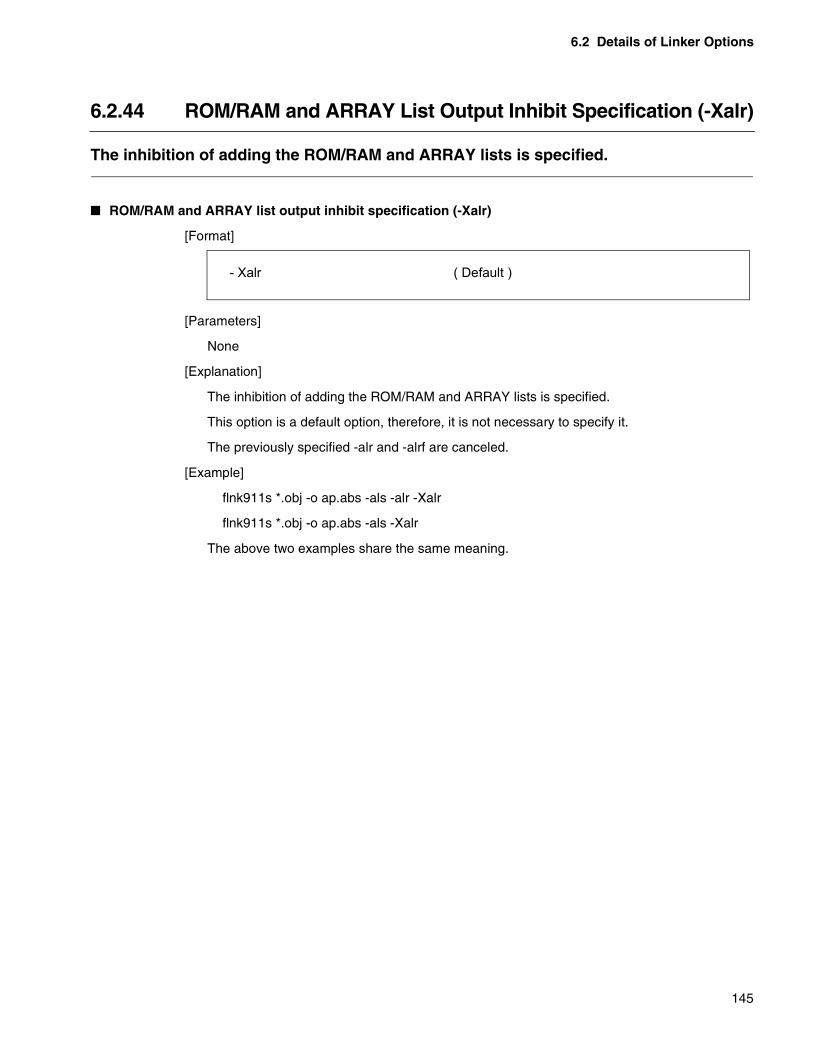
6.2 Details of Linker Options
145
6.2.44 ROM/RAM and ARRAY List Output Inhibit Specification (-Xalr)
The inhibition of adding the ROM/RAM and ARRAY lists is specified.
� ROM/RAM and ARRAY list output inhibit specification (-Xalr)
[Format]
[Parameters]
None
[Explanation]
The inhibition of adding the ROM/RAM and ARRAY lists is specified.
This option is a default option, therefore, it is not necessary to specify it.
The previously specified -alr and -alrf are canceled.
[Example]
flnk911s *.obj -o ap.abs -als -alr -Xalr
flnk911s *.obj -o ap.abs -als -Xalr
The above two examples share the same meaning.
- Xalr ( Default )
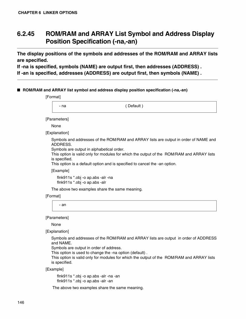
CHAPTER 6 LINKER OPTIONS
146
6.2.45 ROM/RAM and ARRAY List Symbol and Address Display Position Specification (-na,-an)
The display positions of the symbols and addresses of the ROM/RAM and ARRAY listsare specified.If -na is specified, symbols (NAME) are output first, then addresses (ADDRESS) .If -an is specified, addresses (ADDRESS) are output first, then symbols (NAME) .
� ROM/RAM and ARRAY list symbol and address display position specification (-na,-an)
[Format]
[Parameters]
None
[Explanation]
Symbols and addresses of the ROM/RAM and ARRAY lists are output in order of NAME and ADDRESS.Symbols are output in alphabetical order.This option is valid only for modules for which the output of the ROM/RAM and ARRAY lists is specified.This option is a default option and is specified to cancel the -an option.
[Example]
flnk911s *.obj -o ap.abs -alr -naflnk911s *.obj -o ap.abs -alr
The above two examples share the same meaning.
[Format]
[Parameters]
None
[Explanation]
Symbols and addresses of the ROM/RAM and ARRAY lists are output in order of ADDRESS and NAME.Symbols are output in order of address.This option is used to change the -na option (default) .This option is valid only for modules for which the output of the ROM/RAM and ARRAY lists is specified.
[Example]
flnk911s *.obj -o ap.abs -alr -na -anflnk911s *.obj -o ap.abs -alr -an
The above two examples share the same meaning.
- na ( Default )
- an
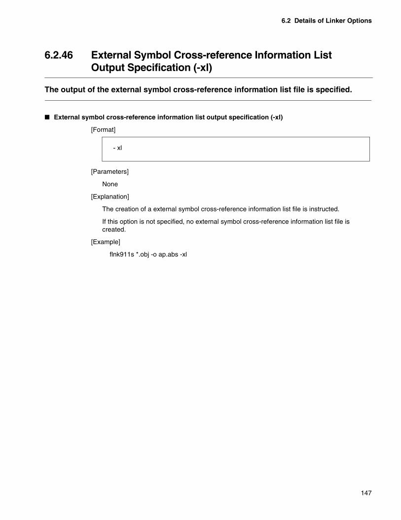
6.2 Details of Linker Options
147
6.2.46 External Symbol Cross-reference Information ListOutput Specification (-xl)
The output of the external symbol cross-reference information list file is specified.
� External symbol cross-reference information list output specification (-xl)
[Format]
[Parameters]
None
[Explanation]
The creation of a external symbol cross-reference information list file is instructed.
If this option is not specified, no external symbol cross-reference information list file is created.
[Example]
flnk911s *.obj -o ap.abs -xl
- xl

CHAPTER 6 LINKER OPTIONS
148
6.2.47 External Symbol Cross-reference Information List FileName Specification (-xlf)
This option is used to change the output destination directory or file name of theexternal symbol cross-reference information list file.
� External symbol cross-reference information list file name specification (-xlf)
[Format]
[Parameters]
<Output file name> Specify the output file name. To change the directory of the output destination, add the path name prior to the output file name.
[Explanation]
The external symbol cross-reference information list file is created with the specified name.
When using this option, the -xl option can be omitted.
If the extension is omitted in the <output file name> specification, the default extension “.mpx” is added.
If this option is not specified, the absolute format load module file name is used whose extension is changed to “.mpx” as the output file name.
[Example]
flnk911s *.obj -o ap.abs -xl -xlf ccp903.mpx
flnk911s *.obj -o ap.abs -xlf ccp903
The above two examples share the same meaning.
- xlf < Output file name >

6.2 Details of Linker Options
149
6.2.48 External Symbol Cross-reference Information List Output Inhibit Specification (-Xxl)
Inhibiting the output of the external symbol cross-reference information list file isspecified.
� External symbol cross-reference information list output inhibit specification (-Xxl)
[Format]
[Parameters]
None
[Explanation]
Inhibiting the output of the external symbol cross-reference information list file is specified
This option is a default option, therefore, it is not necessary to specify it.
The previously specified -xl and -xlf are canceled.
[Example]
flnk911s *.obj -o ap.abs -xl -Xxl
flnk911s *.obj -o ap.abs -Xxl
flnk911s *.obj -o ap.abs
The above three examples share the same meaning.
- Xxl ( Default )

CHAPTER 6 LINKER OPTIONS
150
6.2.49 Local Symbol Information List Output Specification (-sl)
The output of the local symbol information list file is specified.The output of debug information when compiling or assembling is required.
[Format]
[Parameters]
None
[Explanation]
The creation of a local symbol information list file is instructed.
If this option is not specified, no local symbol information list file is created.
To output the local symbol information list file, specify the debug information output option (-g) when compiling, assembling, and linking.
[Example]
flnk911s *.obj -o ap.abs -sl -g
- sl
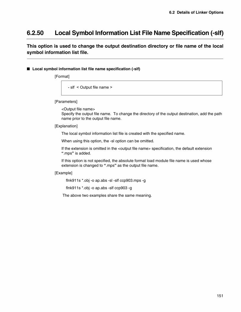
6.2 Details of Linker Options
151
6.2.50 Local Symbol Information List File Name Specification (-slf)
This option is used to change the output destination directory or file name of the localsymbol information list file.
� Local symbol information list file name specification (-slf)
[Format]
[Parameters]
<Output file name> Specify the output file name. To change the directory of the output destination, add the path name prior to the output file name.
[Explanation]
The local symbol information list file is created with the specified name.
When using this option, the -sl option can be omitted.
If the extension is omitted in the <output file name> specification, the default extension “.mps” is added.
If this option is not specified, the absolute format load module file name is used whose extension is changed to “.mps” as the output file name.
[Example]
flnk911s *.obj -o ap.abs -sl -slf ccp903.mps -g
flnk911s *.obj -o ap.abs -slf ccp903 -g
The above two examples share the same meaning.
- slf < Output file name >

CHAPTER 6 LINKER OPTIONS
152
6.2.51 Local Symbol Information List Output Inhibit Specification (-Xsl)
Inhibiting the output of the local symbol information list file is specified.
� Local symbol information list output inhibit specification (-Xsl)
[Format]
[Parameters]
None
[Explanation]
Inhibiting the output of the local symbol information list file is specified.
This option is a default option, therefore, it is not necessary to specify it.
-sl and -slf specified before are canceled.
[Example]
flnk911s *.obj -o ap.abs -sl -Xsl
flnk911s *.obj -o ap.abs -Xsl
flnk911s *.obj -o ap.abs
The above three examples share the same meaning.
- Xsl ( Default )
6.2 Details of Linker Options
153
6.2.52 Section Detail Map List Output Specification (-ml)
The output of the section detail map list file is specified.
� Section detail map list output specification (-ml)
[Format]
[Parameters]
None
[Explanation]
The creation of a section detail map list file is specified.
If this option is not specified, no section detail map list file is created.
[Example]
flnk911s *.obj -o ap.abs -ml
- ml
CHAPTER 6 LINKER OPTIONS
154
6.2.53 Section Detail Map List Name Specification (-mlf)
This option is used to change the output destination directory or file name of thesection detail map list file.
� Section detail map list name specification (-mlf)
[Format]
[Parameters]
<Output file name>Specify the output file name. To change the directory of the output destination, add the path name prior to the output file name.
[Explanation]
The section detail map list file is created with the specified name.
When using this option, the -ml option can be omitted.
If the extension is omitted in the <output file name> specification, the default extension “.mpm” is added.
If this option is not specified, the absolute format load module file name is used whose extension is changed to “.mpm” as the output file name.
[Example]
flnk911s *.obj -o ap.abs -ml -mlf ccp903.mpm
flnk911s *.obj -o ap.abs -mlf ccp903
The above two examples share the same meaning.
- mlf < Output file name >
6.2 Details of Linker Options
155
6.2.54 Section Detail Map List Output Inhibit Specification (-Xml)
Inhibiting the output of the section detail map list file is specified.
� Section detail map list output inhibit specification (-Xml)
[Format]
[Parameters]
None
[Explanation]
Inhibiting the output of the section detail map list file is specified.
This option is a default option, therefore, it is not necessary to specify it.
-ml and -mlf specified before are canceled.
[Example]
flnk911s *.obj -o ap.abs -ml -Xml
flnk911s *.obj -o ap.abs -Xml
flnk911s *.obj -o ap.abs
The above two examples share the same meaning.
- Xml ( Default )

156
MEMO
157
CHAPTER 7 OUTPUT LIST FILE OF THE LINKER
This chapter explains the formats of each list file output by the linker and how to viewthe information.
7.1 Types of List Files Output by the Linker
7.2 Link List File
7.3 Absolute Assemble List File
7.4 External Symbol Cross-reference Information List File
7.5 Local Symbol Information List File
7.6 Section Allocation Detailed Information List File

CHAPTER 7 OUTPUT LIST FILE OF THE LINKER
158
7.1 Types of List Files Output by the Linker
The following five types of list files are output by the linker.• Link list file• Absolute format assemble list• External symbol cross-reference information list• Local symbol information list• Section detail map listWhether to output these files can be selected as options when activating the linker.
� Link list file
The link list file outputs the options for linker activation, input module names, and information about sections and external symbols after module linking.
� Absolute format assemble list
The absolute format assemble list is a list which displays in the absolute format the assemble list output by the assembler in the relative format based on information after module linking.
This list can be referenced when debugging on the assembler language level, and the addresses in each step of the machine language that are unidentifiable in the link list can be known.
� External symbol cross-reference information list
The external symbol cross-reference information list outputs information about external definition symbols of each module after linking and inter-module cross-reference of external reference symbols.
� Local symbol information list
The local symbol information list outputs information about variables and functions including local symbols of each module after linking.
� Section detail map list
The section detail map list creates information about the section allocation of each module after linking.

7.2 Link List File
159
7.2 Link List File
The link list file can be divided into the following three parts depending on theinformation contents.• Control list• Map list• Memory used information list• External symbol listWe explain here the items output in each list.
� Link List File
The link list file can be divided into the following three parts.
❍ Control list
• Specified option
• Input module
• Error message
❍ Map list
• Section name
• Section attributes
• Section allocation address after linking
❍ Memory used information list
• ROM/RAM used information
• Area internal information
• General evaluation value information
❍ External symbol list
• External symbol name
• Types of the definition and reference
• Symbol values
A control character of the page break is output at the boundary of each list.

CHAPTER 7 OUTPUT LIST FILE OF THE LINKER
160
7.2.1 Control List
In the control list, the options specified when the linker was executed and input modulenames are displayed. Errors detected during linking are also displayed.
� List output format of the control list part
The following shows the list output format of the control list part.
Page header
The linker name, list name, date and time, and page number are displayed in the first line.
(1)Option file name display area
If any option file is used, the file name is displayed.
If no option file is used, [** no use **]is displayed.
(2)Linker control option display area
Specified options and valid options by default are displayed.
If an option is specified in any option file, @ is put prior to the option.
(3)Input module display area
File names and module names with the serial number starting with 1 are displayed.
(4)Error message display area
Error messages detected during processing are displayed.
If no error has been detected, [** Nothing **] is displayed.
FR Family Softune Linker Control List YYYY-MM-DD hh:mm:ss Page: 1
Option File(s)
(1) Option file name display area
Control(s)
(2) Linker control option display area
Input Module(s)
(3) Input module display area
Error(s)
(4) Error message display area
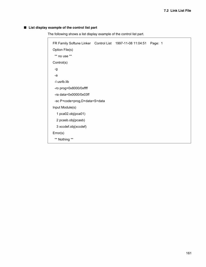
7.2 Link List File
161
� List display example of the control list part
The following shows a list display example of the control list part.
FR Family Softune Linker Control List 1997-11-08 11:04:51 Page: 1
Option File(s)
** no use **
Control(s)
-g
-a
-l usrlb.lib
-ro prog=0x8000/0xffff
-ra data=0x0000/0x03ff
-sc P+code=prog,D+data+S=data
Input Module(s)
1 pca02.obj(pca01)
2 pcasb.obj(pcasb)
3 xccdef.obj(xccdef)
Error(s)
** Nothing **

CHAPTER 7 OUTPUT LIST FILE OF THE LINKER
162
7.2.2 Map List
In the map list, the section names, content types, attributes, and section allocationaddresses after linking are displayed.
� List output format of the map list part
The following shows the list output format of the map list part.
Page header
The linker name, list name, date and time, and page number are displayed in the first line.
(1) Map information display area
Map information is displayed in order of start address, or if the start address is the same, in order of section occurrence.
S-Addr : Section start address(hexadecimal)
E-Addr : Section end address(hexadecimal)
Size : Section size (hexadecimal)
Section : Section content type
The section content type is displayed.
CODE Program sectionDATA Data sectionCONST Data section with initial valuesSTACK Stack sectionDIR direct section(F2MC family only)DIRCONST direct section with initial values(F2MC family only)IO IO section
After the section type, the link attribute is displayed.
P Simple concatenation linkC Shared linkA No link
Type : Section attributes
The following attributes are displayed from left.
R/- Read enabled/disabledW/- Wirte enabled/disabledX/- Executable/non-executableI/- Initial value Yes/No
Al : Boundary adjustment value for section allocation(hexadecimal)
If the boundary adjustment value is 0x100 or greater, “**” is displayed.
FR Family Softune Linker Mapping List YYYY-MM-DD hh:mm:ss Page: 2
S-Addr. - E-Addr. Size Section type Al Sec.(Top **) C
(1) Map information display area

7.2 Link List File
163
Sec.(Top **) : Section name
“**”indicates how many digits of the section name can be displayed with the specified page width.
(*1)The end address of a section with the section size 0 is displayed by [........].
� List display example of the map list part
The following shows a list display example of the map list part.
FR Family Softune Linker Mapping List 1997-11-08 11:04:51 Page: 2
S-Addr. - E-Addr. Size Section type Al Sec.(Top 81) C
00000000 - 0000001F 00000020 DATA P RW- 08 REL D
00000020 - 00000039 0000001A DATA P RW- 02 REL data
0000003A - 00000053 0000001A STAK P RW- 02 REL S
00000054 - 0000006D 0000001A DATA P RW-I 02 REL init
00008000 - 00008039 0000003A CODE P R-XI 02 REL P
0000803A - 00008053 0000001A CODE P R-XI 02 REL code
00008054 - 0000806D 0000001A DATA P R--I 02 REL # init
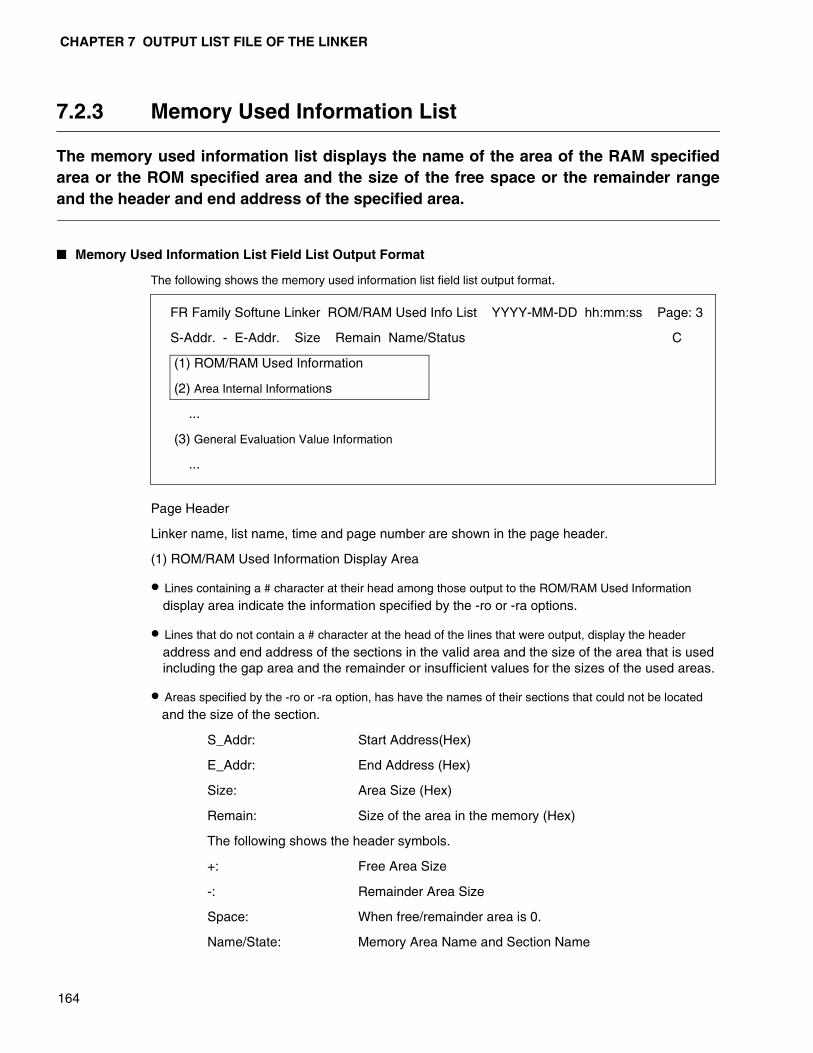
CHAPTER 7 OUTPUT LIST FILE OF THE LINKER
164
7.2.3 Memory Used Information List
The memory used information list displays the name of the area of the RAM specifiedarea or the ROM specified area and the size of the free space or the remainder rangeand the header and end address of the specified area.
� Memory Used Information List Field List Output Format
The following shows the memory used information list field list output format.
Page Header
Linker name, list name, time and page number are shown in the page header.
(1) ROM/RAM Used Information Display Area
• Lines containing a # character at their head among those output to the ROM/RAM Used Information
display area indicate the information specified by the -ro or -ra options.
• Lines that do not contain a # character at the head of the lines that were output, display the header
address and end address of the sections in the valid area and the size of the area that is used including the gap area and the remainder or insufficient values for the sizes of the used areas.
• Areas specified by the -ro or -ra option, has have the names of their sections that could not be located
and the size of the section.
S_Addr: Start Address(Hex)
E_Addr: End Address (Hex)
Size: Area Size (Hex)
Remain: Size of the area in the memory (Hex)
The following shows the header symbols.
+: Free Area Size
-: Remainder Area Size
Space: When free/remainder area is 0.
Name/State: Memory Area Name and Section Name
FR Family Softune Linker ROM/RAM Used Info List YYYY-MM-DD hh:mm:ss Page: 3
S-Addr. - E-Addr. Size Remain Name/Status C
(1) ROM/RAM Used Information
(2) Area Internal Informations
...
(3) General Evaluation Value Information
...
7.2 Link List File
165
(2) Area Internal Information Area
The area internal information area displays the free area of the valid area, the used area and the gap area in a map image. The information displayed in this area is information only of the located section with regard to the specified area.
S_Addr: Area Start Address (Hex)
E_Addr: Area End Address (Hex)
Size: Area Size (Hex)
Name/State: Area Type
FREE: Free Area
USED: Used Area
GAP: Gap Area
(3) General Evaluation Value Information
General Evaluation Value Information shows the following types of information for the overall ROM and RAM areas.
1 Total value of the specified area (Total)
2 Total value of the used area (Used) (Note: Includes the Gap area.)
3 Total value of the free or remainder area (Remainder)

CHAPTER 7 OUTPUT LIST FILE OF THE LINKER
166
� Example Display of the Memory Used Information List Field List
The following is an example of the Memory Used Information List Field list display.
Note: 1. Memory area information that has sections not located that were to be located in the memoryarea by the automatic locating option indicates the status with added section size. (When thenumerical value expression exceeds 0xFFFFFFFF, the lower part of the 32 bit is displayedof that value.) 2. When Mode 2 of the automatic location option is specified, this displays the memoryarea specified last for the section not located (for either the ROM area or the RAM area). 3. Sections specified by the user location are included in the memory area which includethe section header address.

MEMO
167

CHAPTER 7 OUTPUT LIST FILE OF THE LINKER
168
7.2.4 Symbol List
In the symbol list, the external symbol names, definitions, reference types, and symbolvalues are displayed.
� List output format of the symbol list part
Page header
The linker name, list name, date and time, and page number are displayed in the first line.
(1) Symbol list display area
Symbol Value : Symbol address or symbol value (hexadecimal)
Type : Symbol type
One of the following is displayed.
Addr. Address level
EQU EQU defined symbol
bit Bit attributes
Def. : Symbol definition
One of the following is displayed.
OM/LM Defined in the input object module or relative format load module.
LIB Defined in the linked library
user Symbol whose value is temporarily set using the -df option.
Symbol Name: Symbol name
“**” indicates how many digits of the symbol name can be displayed with the specified page width.
(*)If a symbol is referenced, the symbol name is displayed as it is. If it is not referenced, @ is displayed prior to the symbol name.
FR Family Softune Linker Symbol List YYYY-MM-DD hh:mm:ss Page: 3
Symbol Value Type Def Symbol Name(Top **) C
(1) Symbol list display area

� List display example of the symbol list part
The following shows a list display example of the symbol list part.
FR Family Softune Linker Symbol List YYYY-MM-DD hh:mm:ss Page: 3
Symbol Value Type Def Symbol Name(Top **) C
00000004 (ABS) Addr.OM/LM _Filename
00000008 (ABS) Addr.OM/LM _c1
000000C4 (ABS) Addr. OM/LM _main
00000018 (ABS) Addr. OM/LM _ulval
169

CHAPTER 7 OUTPUT LIST FILE OF THE LINKER
170
7.3 Absolute Assemble List File
The absolute format assemble list output by the linker consists of the following parts.• Header• Information list• ROM/RAM and ARRAY list• Assemble source list• Section information list• Cross-reference listWe explain here the items output in each list.
� Absolute Assemble List File
❍ Header
Output in the first line of each page.
❍ Information list
The information list output by the assembler is output as it is.
❍ ROM/RAM and ARRAY list
• ROM/RAM listGlobal symbol names allocated in the ROM/RAM area and absolute addressinformation are output.
• ARRAY listArray element names, structure member names, and absolute address information areoutput.
If the option-alr is specified, the ROM/RAM and ARRAY lists are displayed. If -Xalr is specified, the ROM/RAM and ARRAY lists are not displayed.
❍ Assemble source list
The assemble source list displays a variety of information about assembling of the source program in units of lines. Error information, locations, object code are displayed.
❍ Section information list
Names and attributes defined in the source program are displayed.
❍ Cross-reference list
Definitions of the symbol names used in the source program and references are displayed using the line numbers.
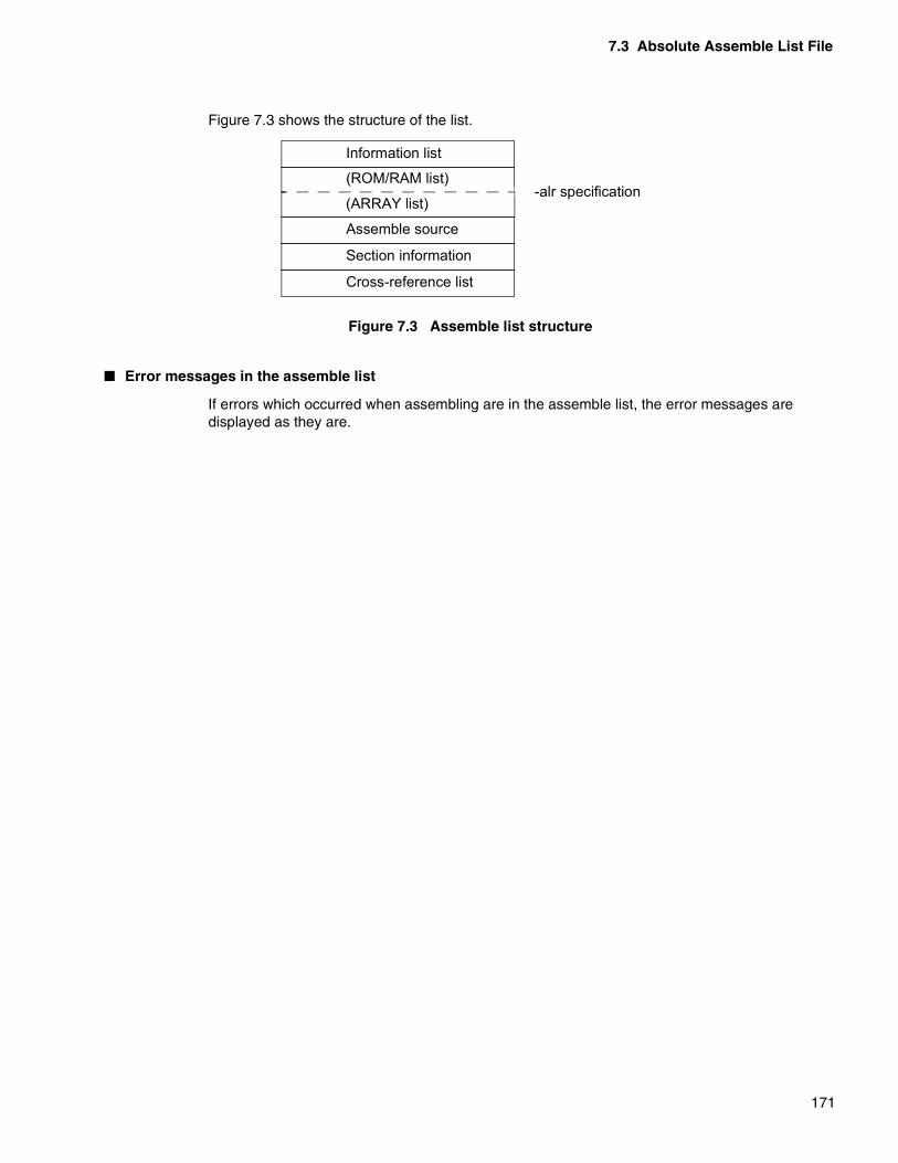
7.3 Absolute Assemble List File
171
Figure 7.3 shows the structure of the list.
Figure 7.3 Assemble list structure
� Error messages in the assemble list
If errors which occurred when assembling are in the assemble list, the error messages are displayed as they are.
Information list
(ROM/RAM list)
(ARRAY list)
Assemble source
Section information
Cross-reference list
-alr specification

CHAPTER 7 OUTPUT LIST FILE OF THE LINKER
172
7.3.1 Header and Information List
The header consists of four lines.On the first page of the list, the information list (settings when activating theassembler, number of errors, number of warnings, source file names, include filenames, option file names) is displayed after the header.
� Header format
The header consists of four lines. It is displayed at the head of each page. The first and second lines have the same format for all assemble lists, and the third line depends on each source program. The following shows the header format.
[1st and 2nd lines]
[3rd line]
The contents of the original assemble list are displayed as they are.
[4th line]
A blank line is output.
FR Family Softune Linker VxxLxx yyyy-mm-dd hh:mm:ss Page: xxxx
Tool name Absolute assemble list creation date Page number
- Each list name - (Module name)

MEMO
173
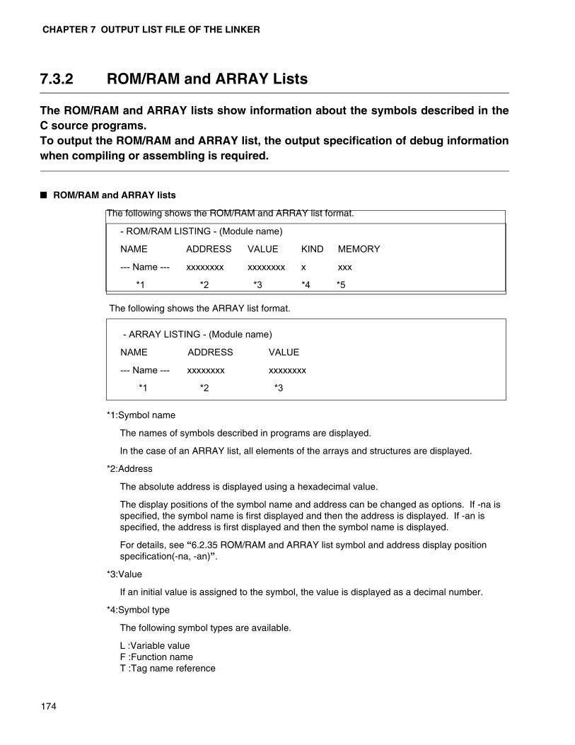
CHAPTER 7 OUTPUT LIST FILE OF THE LINKER
174
7.3.2 ROM/RAM and ARRAY Lists
The ROM/RAM and ARRAY lists show information about the symbols described in theC source programs.To output the ROM/RAM and ARRAY list, the output specification of debug informationwhen compiling or assembling is required.
� ROM/RAM and ARRAY lists
The following shows the ROM/RAM and ARRAY list format.
The following shows the ARRAY list format.
*1:Symbol name
The names of symbols described in programs are displayed.
In the case of an ARRAY list, all elements of the arrays and structures are displayed.
*2:Address
The absolute address is displayed using a hexadecimal value.
The display positions of the symbol name and address can be changed as options. If -na is specified, the symbol name is first displayed and then the address is displayed. If -an is specified, the address is first displayed and then the symbol name is displayed.
For details, see “6.2.35 ROM/RAM and ARRAY list symbol and address display position specification(-na, -an)”.
*3:Value
If an initial value is assigned to the symbol, the value is displayed as a decimal number.
*4:Symbol type
The following symbol types are available.
L :Variable valueF :Function nameT :Tag name reference
- ROM/RAM LISTING - (Module name)
NAME ADDRESS VALUE KIND MEMORY
--- Name --- xxxxxxxx xxxxxxxx x xxx
*1 *2 *3 *4 *5
- ARRAY LISTING - (Module name)
NAME ADDRESS VALUE
--- Name --- xxxxxxxx xxxxxxxx
*1 *2 *3

7.3 Absolute Assemble List File
175
*5:Memory allocation
The memory area to which a symbol is allocated is displayed.
ROM:ROM areaRAM:RAM area
[Example 1]
[Example 2]
- ROM/RAM LISTING - (sample1)
NAME ADDRESS VALUE KIND MEMORY
_Line 00002B8 000100 L ROM
_Nameleng 000004C 000016 L RAM
_symref 0005592 T ROM
_Tflg 0000763 000002 L RAM
- ARRAY LISTING - (sample1)
NAME ADDRESS VALUE
_symref[0].val 0005592 000100
_symref[0].nam 0005596 000002
_symref[0].atr 0005598 000016
_symref[1].val 000559A 012000
_symref[1].nam 000559E 000002
_symref[1].atr 00055A0 000016
_Xpcr[0][0] 0001066 000400
_Xpcr[0][1] 00010A0 000120

CHAPTER 7 OUTPUT LIST FILE OF THE LINKER
176
7.3.3 Assemble Source List
The assemble source list is displayed with the location part using the absolute addressand the object code part using the determined code after linking.
� Assemble source list
The following shows the assemble source list format.
The first line of the above format is called the source list header. The source list header is displayed on each page.
*1:Section acronym
The first two characters of a section name are displayed.
*2:Location
The 32-bit location value is displayed as a hexadecimal value.
*3:Object code
The determined object code after linking is displayed as hexadecimal values. If the object code cannot be displayed in one line, it is displayed in multiple lines.
*4:Object code type
The attributes of values contained in object code are displayed in the following order of priority.
I:External reference valueS:Section valueBlank:Absolute value
Since “R” displayed in the relative assemble list is conver ted to an absolute value in the absolute assemble list, it is not displayed.
*5:Line number
The line number is displayed as a decimal 5-digit number.
- SOURCE LISTING - (Module name)
SN LOC OBJ LINE SOURCE
xx xxxxxxxx xxxxxxxxxxxxxxx x xxxx x --------------
*1 *2 *3 *4 *5 *6 *7
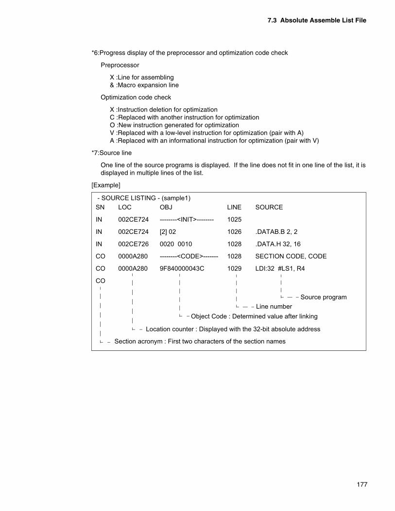
7.3 Absolute Assemble List File
177
*6:Progress display of the preprocessor and optimization code check
Preprocessor
X :Line for assembling& :Macro expansion line
Optimization code check
X :Instruction deletion for optimizationC :Replaced with another instruction for optimizationO :New instruction generated for optimizationV :Replaced with a low-level instruction for optimization (pair with A)A :Replaced with an informational instruction for optimization (pair with V)
*7:Source line
One line of the source programs is displayed. If the line does not fit in one line of the list, it is displayed in multiple lines of the list.
[Example]
- SOURCE LISTING - (sample1)SN LOC OBJ LINE SOURCE
IN 002CE724 --------<INIT>-------- 1025
IN 002CE724 [2] 02 1026 .DATAB.B 2, 2
IN 002CE726 0020 0010 1028 .DATA.H 32, 16
CO 0000A280 --------<CODE>------- 1028 SECTION CODE, CODE
CO 0000A280 9F840000043C 1029 LDI:32 #LS1, R4
CO
Line number Source program
Location counter : Displayed with the 32-bit absolute address
Section acronym : First two characters of the section names
Object Code : Determined value after linking
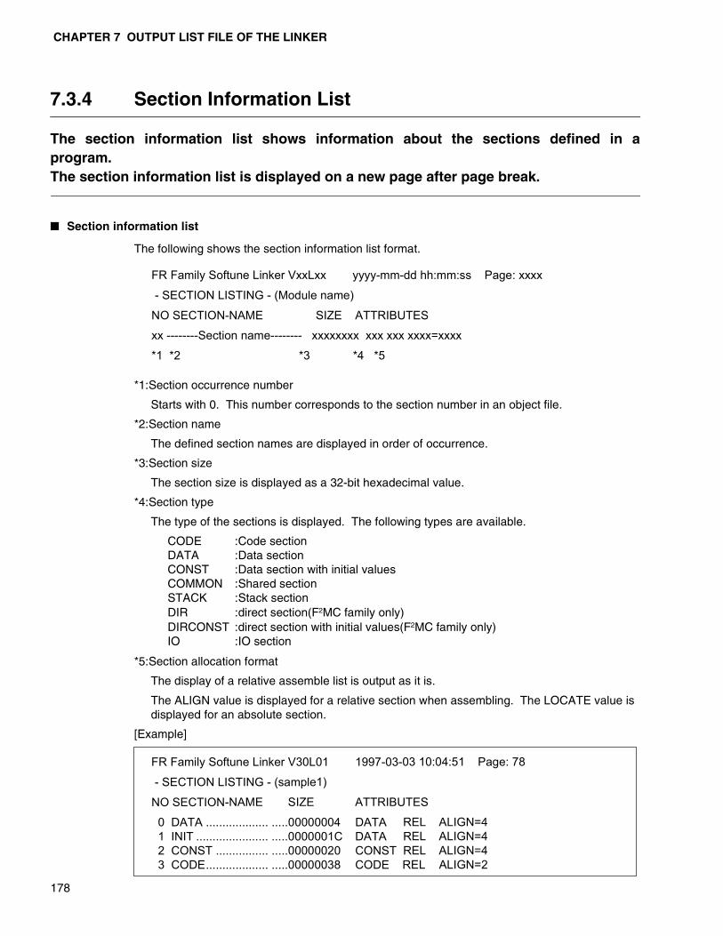
CHAPTER 7 OUTPUT LIST FILE OF THE LINKER
178
7.3.4 Section Information List
The section information list shows information about the sections defined in aprogram.The section information list is displayed on a new page after page break.
� Section information list
The following shows the section information list format.
*1:Section occurrence number
Starts with 0. This number corresponds to the section number in an object file.
*2:Section name
The defined section names are displayed in order of occurrence.
*3:Section size
The section size is displayed as a 32-bit hexadecimal value.
*4:Section type
The type of the sections is displayed. The following types are available.
CODE :Code sectionDATA :Data sectionCONST :Data section with initial valuesCOMMON :Shared sectionSTACK :Stack sectionDIR :direct section(F2MC family only)DIRCONST :direct section with initial values(F2MC family only)IO :IO section
*5:Section allocation format
The display of a relative assemble list is output as it is.
The ALIGN value is displayed for a relative section when assembling. The LOCATE value is displayed for an absolute section.
[Example]
FR Family Softune Linker VxxLxx yyyy-mm-dd hh:mm:ss Page: xxxx
- SECTION LISTING - (Module name)
NO SECTION-NAME SIZE ATTRIBUTESxx --------Section name-------- xxxxxxxx xxx xxx xxxx=xxxx
*1 *2 *3 *4 *5
FR Family Softune Linker V30L01 1997-03-03 10:04:51 Page: 78
- SECTION LISTING - (sample1)
NO SECTION-NAME SIZE ATTRIBUTES
0 DATA ................... .....00000004 DATA REL ALIGN=4 1 INIT ...................... .....0000001C DATA REL ALIGN=4 2 CONST ................ .....00000020 CONST REL ALIGN=4 3 CODE................... .....00000038 CODE REL ALIGN=2
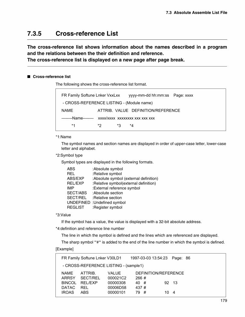
7.3 Absolute Assemble List File
179
7.3.5 Cross-reference List
The cross-reference list shows information about the names described in a programand the relations between the their definition and reference.The cross-reference list is displayed on a new page after page break.
� Cross-reference list
The following shows the cross-reference list format.
*1:Name
The symbol names and section names are displayed in order of upper-case letter, lower-case letter and alphabet.
*2:Symbol type
Symbol types are displayed in the following formats.
ABS :Absolute symbolREL :Relative symbolABS/EXP :Absolute symbol (external definition)REL/EXP :Relative symbol(external definition)IMP :External reference symbolSECT/ABS :Absolute sectionSECT/REL :Relative sectionUNDEFINED :Undefined symbolREGLIST :Register symbol
*3:Value
If the symbol has a value, the value is displayed with a 32-bit absolute address.
*4:definition and reference line number
The line in which the symbol is defined and the lines which are referenced are displayed.
The sharp symbol "#" is added to the end of the line number in which the symbol is defined.
[Example]
FR Family Softune Lnker VxxLxx yyyy-mm-dd hh:mm:ss Page: xxxx
- CROSS-REFERENCE LISTING - (Module name)
NAME ATTRIB. VALUE DEFINITION/REFERENCE
--------Name-------- xxxx/xxxx xxxxxxxx xxx xxx xxx
*1 *2 *3 *4
FR Family Softune Lnker V30LD1 1997-03-03 13:54:23 Page: 86
- CROSS-REFERENCE LISTING - (sample1)
NAME ATTRIB. VALUE DEFINITION/REFERENCEARRSY SECT/REL 000021C2 266 #BINCOL REL/EXP 00000308 40 # 92 13DATAC REL 00006D58 437 #IROAS ABS 00000101 79 # 10 4

CHAPTER 7 OUTPUT LIST FILE OF THE LINKER
180
7.4 External Symbol Cross-reference Information List File
The symbol cross-reference information list file displays the external definitionsymbols of each object module after linking and cross-reference information betweenmodules of the external reference symbols.
� External symbol cross-reference information list file
The following shows the output format of the external symbol cross-reference information list.
❍ Module(s)
The serial number starting with 1 is added to indicate the module name.
❍ symbol
The symbol names are displayed. (by default, up to 20 characters)
External Symbol Cross-reference List yyyy-mm-dd hh:mm:ss Page: 1
Module(s)
1. module01
2. module02
:
15. module15
External symbol Cross-reference List yyyy-mm-dd hh:mm:ss Page: 2
--- symbol --- --- type/value --- --- module (No.) ---
extsym1 Addr. 0x000012E8 1# 2 3 4 5 6 8 11 12 14
extsym2 Addr. 0x000C3F34 2 3 4# 5 6 8 11 12 14
extsym3 Addr. 0x000012E6 1# 2 3 4 5 6 8 11 12 13 14 15
extsym4 ???? 0x00000000 2 5 8
extsymxxlongxx+ Addr. 0x000CA8ee 4 5 6 11 12 14#
longxx
extsymunresolved ???? 0x00000000 10 15
extsym7 Addr. 0x000014CA 12 15#
n1m EQU 0XFFFFFFFF 1 3 4 7 11 12 13 14 15#
n1p EQU 0x00000001 4 5 6 11 12 14#

7.4 External Symbol Cross-reference Information List File
181
❍ type/value
The following types are available.
• Addr. :Address
• EQU :EQU symbol
• Bit :Bit symbol
• ???? :Undefined
“value” indicates a value. In the case of a bit symbol, its bit position is displayed in parentheses.
❍ module (No.)
Modules which are defined/referenced are displayed using their Nos. The # symbol indicates a defined module.

CHAPTER 7 OUTPUT LIST FILE OF THE LINKER
182
7.5 Local Symbol Information List File
The local symbol information list file displays information about the variables andfunctions which include local symbols for each module constituting an absolute formatload module.Since this list is created based on debug information when compiling and assembling,it is necessary to specify the -g option.
� Local symbol information list file
The following shows the output format of the local symbol information list.
Local Symbol List yyyy-mm-dd hh:mm:ss Page: 1Module(s) 1. module01 2. module02 : 15. module15
Local Symbol List yyyy-mm-dd hh:mm:ss Page: 2 === Module No. 1 (module01) === --- symbol --- --- kind --- --- val --- func1(int) Func. g 0x000C3F34 localstatic1 Var. s 0x000012EE localstatic2 Var. s 0x000012F0
: === Module No. 15 (module15) === --- symbol --- --- kind --- --- val --- operator +(USDollar &, USDollar &) Func. g 0x00000000 main Func. g 0x0000004A USDollar::USDollar(unsigned int) Func. g 0x000000CA Atable loc. s 0xFFFFFFFC Extsym Var. g 0x00001342

7.5 Local Symbol Information List File
183
❍ Module(s)
The serial number star.5ting with 1 is added to indicate the module name.
❍ symbol
The symbol names are displayed.
Symbols used in a function are displayed in the 3rd and following columns.
Up to 20 characters of the symbol name are displayed in one line of the list.
❍ Kind
The following symbol types are displayed.
Var. :Variable(C)Func. :Function(C)loc. :Local(C)Addr. :Address(ASM)EQU :EQU symbol(ASM)bit :bit symbol(ASM)???? :Undefineds :static(C)g :global(C)
“value” indicates a value.
❍ val
The value of a symbol is indicated.
For loc., an offset value is displayed.
(*)No detailed information about structures (member names) nor the typedef definitions are displayed.

CHAPTER 7 OUTPUT LIST FILE OF THE LINKER
184
7.6 Section Allocation Detailed Information List File
The section allocation detailed information list file creates information about sectionallocation for each module constituting an absolute format load module.A mapping list of a whole section is displayed in one map list file and more detailedinformation about section allocation can be found.
� Section Allocation Detailed Information List File
The following shows the output format of the section allocation detailed information list.
Section Mapping List yyyy-mm-dd hh:mm:ss Page: 1
Module(s)
1. module01
2. module02
:
15. module15
Section Mapping List yyyy-mm-dd hh:mm:ss Page: 2S.Addr. -E.Addr. Size Section Type Al M.No. Sec.(Top 18) 00000000-00000048 00000049 DATA P RW-- 04 1 data 0000004A-000003E1 00000348 DATA P RW-- 04 2 data 000003E2-00000403 00000022 DATA P RW-- 04 3 data 00000404-........ 00000000 DATA P RW-I 04 4 data 00000404-00000663 00000260 DATA P RW-I 04 4 init 00000664-00000763 00000100 STACK P RW-- 04 6 sectionnametoolong+
toolong 000C0000-000C03DF 000003E0 CODE P R-XI 02 1 code 000C03E0-000C0441 00000062 CODE P R-XI 02 2 code 000C0442-000C148B 0000104A CODE P R-XI 02 3 code*000C148C-000C201D 00000B92 CODE P R-XI 02 4 code*000C2000-000C2203 00000204 CODE P R-XI 02 5 subprog1 000C3000-000C325F 00000260 DATA P R--I 04 4 #init
7.6 Section Allocation Detailed Information List File
185
❍ Module(s)
The serial number starting with 1 is added to indicate the module name.
❍ S.Addr.-E.Addr.
Section's start and end addresses.
A section with overlapping addresses has (*) prior to its section name.
If the size of a section is 0, the end address of it is displayed as “........”.
❍ Size
A section in which allowed address space is overflowed is displayed with the maximum size + 1.
❍ Section
The following section content types are available.
CODE :Program sectionDATA :Data sectionCONST :Data section with initial valuesSTACK :Stack sectionDIR :direct section(F2MC Family only)DIRCONST :Direct section with initial values(F2MC Family only)IO :IO section
The link attribute is added to the end of the section type.
P :Simple concatenation linkC :Shared linkA :no link
❍ type
The following attributes are displayed from left.
R/- :Read enabled/disabledW/- :Write enabled/disabledX/- :Executable/non-executableI/- :Initial value Yes/No
❍ Al
The boundary adjustment value for section allocation is displayed as hexadecimal values.
❍ M.No.
The module numbers are displayed. Module numbers displayed in Module(s) are displayed.
❍ Sec.(Top xx)
The section names are displayed. xx of (Top xx) has the number of characters that allows the section name to be displayed in one line.
# prior to a section name indicates that data with initial values to be transferred to RAM before execution is allocated in the section.

186
MEMO
187
CHAPTER 8 LINKER RESTRICTIONS AND Q&A
This chapter explains about linker restrictions and Q&A for use.
8.1 Linker Restrictions
8.2 Q&A for Using the Linker
CHAPTER 8 LINKER RESTRICTIONS AND Q&A
188
8.1 Linker Restrictions
There is no particular restriction on the number of input files and sections that can beprocessed when using the linker. However there are some restrictions when using thewild card in the input files and library files.
� Linker restriction
The linker has no restriction on the number of input files, sections, or symbols that can be processed. If it becomes necessary to register the section names or symbols names for internal processing of the linker, memory is dynamically allocated. And processing is possible until all memory that can be used by the linker is used up.
If it becomes impossible to continue processing, a message to report insufficient memory is issued and then the linker processing ends.
� Linker reservation symbol
In the linker, symbols with the “_ROM_section name”, “_RAM_section name” are created automatically for each section using the ROM > RAM transfer function.
Therefore, if a symbol of the same type is defined in a user program, “W1327L:This symbol is already defined (symbol name)” is generated. The user must not define symbols with the “_ROM_section name” and “_RAM_section name”.
� Restrictions on the object file format
Restrictions of the linker are listed below. There are following restrictions on the numbers of symbols and others that can be managed in object files.
Note:The files here mean object files. When using relative format load module files andincremental link files, count them as the total number of input object files when creatingthem.
Number of input files 65535Number of sections (per file) 65535Number of external definition symbols (per file) 65535Number of external reference symbols (per file) 65535

8.2 Q&A for Using the Linker
189
8.2 Q&A for Using the Linker
Section 8.2 shows the questions and answers on using a linker.
� Using the wild card
Q. There are a large number of input object module files. Can the wild card still be used?
A. If you use the wild card for specifying the input file on the command line, the linker expands and executes it. You can specify the input file name in an option file, and the wild card can also be used here. Refer to the following example for using the wild card.
Example. flnk911s *.obj -o outfile.absflnk911s mactrl.obj xz???.obj
Q. The wild card can be used when specifying section allocation, but how can I use the wild card?
A. The wild card may be useful when many sections with the same content type should be unified or when programs are created using many section names. It may become necessary to decide characters to become the keywords when naming the section names, considering the use of the wild card.
Example. Section names are defined with the names like DTdata1, DTdata2, DTdata3, DTdata4 ....for the sections whose content type is data, and the names like CDprog1, CDprog2, CDprog3, CDprog4.... for the sections whose content type is code.In this case, the following specification method can be selected. (Only the -sc option part is shown)-sc DTdata1+DTdata2+DTdata3+DTdata4=0x1000, CDprog1+CDprog2+CDprog3+CDprog4=0X3000 -sc DT*=0x1000,CD*=0x3000 -sc */data=0x1000,*/code=0x3000

CHAPTER 8 LINKER RESTRICTIONS AND Q&A
190
� Handling variables with initial values
Q. When developing embedded programs using C compilers, variables with initial values are created. Since these variables are rewritten during execution of programs, they must be on RAM during execution. Tell us the procedure for creating programs and precautions.
A1. [FR family and F2MC-8L family]In imbedded programs, variables with initial values are on ROM first and they must be on RAM when they are referenced. Therefore, programs become inoperable if the reference address in programs is not set to RAM and a mechanism to transfer initial data from ROM to RAM before application execution is not implemented.In the FR family and F2MC-8L family, this mechanism is implemented by using the ROM > RAM transfer section function supported by the linker.Variables with initial values generated by the FR family and F2MC-8L family compilers are gathered in the INIT section.There is no need of particular care when creating programs except the total number of bytes of the variables with initial values and RAM size.For the ROM > RAM transfer section function, see “5.9 Sections to be Transferred from ROM to RAM”.The user must write a program to transfer initial value data using assembler languages.Example 1 shows “Program example for transferring initial value data”.
(Continued)
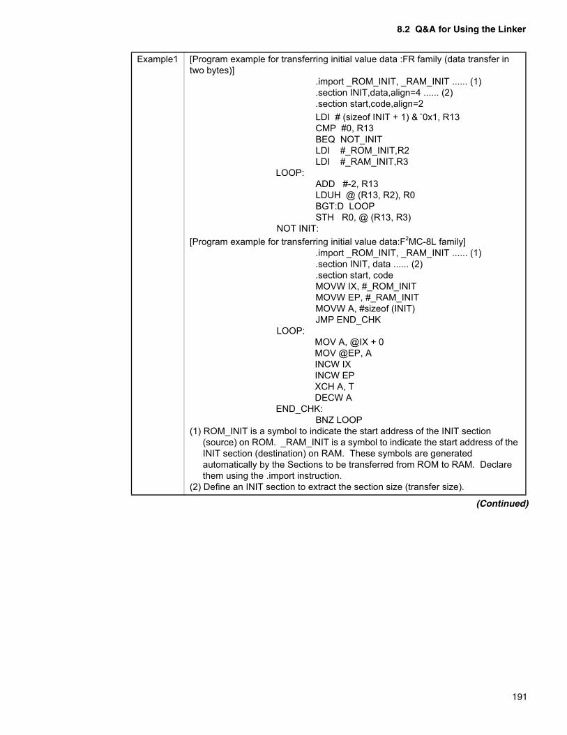
8.2 Q&A for Using the Linker
191
Example1 [Program example for transferring initial value data :FR family (data transfer in two bytes)]
.import _ROM_INIT, _RAM_INIT ...... (1)
.section INIT,data,align=4 ...... (2)
.section start,code,align=2LDI # (sizeof INIT + 1) & ~0x1, R13CMP #0, R13BEQ NOT_INITLDI #_ROM_INIT,R2LDI #_RAM_INIT,R3
LOOP:ADD #-2, R13LDUH @ (R13, R2), R0BGT:D LOOPSTH R0, @ (R13, R3)
NOT INIT:[Program example for transferring initial value data:F2MC-8L family]
.import _ROM_INIT, _RAM_INIT ...... (1)
.section INIT, data ...... (2)
.section start, codeMOVW IX, #_ROM_INITMOVW EP, #_RAM_INITMOVW A, #sizeof (INIT)JMP END_CHK
LOOP:MOV A, @IX + 0MOV @EP, AINCW IXINCW EPXCH A, TDECW A
END_CHK:BNZ LOOP
(1) ROM_INIT is a symbol to indicate the start address of the INIT section (source) on ROM. _RAM_INIT is a symbol to indicate the start address of the INIT section (destination) on RAM. These symbols are generated automatically by the Sections to be transferred from ROM to RAM. Declare them using the .import instruction.
(2) Define an INIT section to extract the section size (transfer size).
(Continued)
CHAPTER 8 LINKER RESTRICTIONS AND Q&A
192
A2. [F2MC-16 family]In imbedded programs, variables with initial values are on ROM first and they must be on RAM when they are referenced. Therefore, programs become inoperable if the reference address in programs is not set to RAM and a mechanism to transfer initial data from ROM to RAM before application execution is not implemented.
- If the memory model is small or mediumVariables with initial values generated by the F2MC-16 family C compilers are gathered in the INIT section (used for execution) and DCONST section (initial data is stored).Therefore, there is no need of particular care when creating programs except the total number of bytes of the variables with initial values and RAM size.The user must write a program to transfer initial value data from DCONST to INIT.Example 2a shows “Program example for transferring initial value data”.
- If the memory model is compact or large
Variables with initial values generated by the F2MC-16 family C compilers are generated for each module. They are gathered in the “INIT_module name” section to be used for execution and in the “DCONST_module name” section (initial data is stored). The information is set in the DTRANS section.Therefore, there is no need of particular care when creating programs except the total number of bytes of the variables with initial values and RAM size.The user must write a program to transfer initial value data based on information set in DTRANS.Example 2b shows “Program example for transferring initial value data”.
Example 2a
[Program example for transferring initial value data:The memory model is either small or medium]
.section DCONST, const ...... (1)DCONST_S
.section INIT, data ...... (2)INIT_S
.section start, codeMOV A, #bnksym (DCONST_S)MOV ADB, AMOV A, #bnksym (INIT_S)MOV DTB, AMOVW RW0, #sizeof (INIT)MOVW A, #INIT_SMOVW A, #DCONST_SMOVSI DTB, ADB
(1) DCONST_S is a symbol to indicate the start address of the DCONST section (source) on ROM.
(2) INIT_S is a symbol to indicate the start address of the INIT section (destination) on RAM.These symbols must be defined at the start of the sections, and so the program to transfer initial value data must be linked first.
(Continued)
8.2 Q&A for Using the Linker
193
Example 2b
[Program example for transferring initial value data:The memory model is either compact or large]
.section DTRANS, constDTRANS_S
.section start, codeMOV A, #bnksym (DTRANS_S)MOV DTB, AMOVW RW1, #DTRANS_SBRA LABEL2
LABEL1:MOVW A, @RW1+6MOV USB, AMOVW A, @RW1+2MOV ADB, AMOVW A, @RW1+4MOVW A, @RW1MOVW RW0, @RW1+8MOVSI SPB, ADBMOVN A, #10ADDW RW1, A
LABEL2:MOVW A, RW1SUBW A, #DTRANS_SCMPW A, #sizeof (DTRANS)BNE LABEL1
(1) DTRANS_S is a symbol to indicate the start address of the DTRANS section (transfer information storing table) on ROM.
These symbols must be defined at the start of the sections, and so the program to transfer initial value data must be linked first.
(Continued)

194
MEMO

195
PART 3 LIBRARIAN
Part 3 describes the specifications, options, and output lists of a librarian.
CHAPTER 9 SPECIFICATIONS OF A LIBRARIAN
CHAPTER 10 OPTIONS A LIBRARIAN
CHAPTER 11 LIST FORMATS OF A LIBRARIAN
CHAPTER 12 RESTRICTIONS AND QUESTIONS AND ANSWERS ON A LIBRARIAN

196
MEMO

197
CHAPTER 9 SPECIFICATIONS OF A LIBRARIAN
Chapter 9 describes the functions and the function types of a librarian. A librarian is atool used to create a library file.
9.1 Functions of a Librarian
9.2 Function Types of a Librarian
9.3 Creating and Editing a Library File
9.4 Extracting a Module from a Library File
9.5 Deleting Debugging Information of a Library
9.6 Checking and Displaying the Contents of a Library File
9.7 Mixing of Objects for a F2MC-16 Family Librarian

198
MEMO

9.1 Functions of a Librarian
199
9.1 Functions of a Librarian
A librarian is a tool used to create a library file by combining multiple object modulesthat an assembler has output
� Roles of a librarian
To develop a program, divide a source program for each function into modules, each of which you then compile and assemble.
A linker then combines the compiled and assembled modules into one to create the target program.
A librarian is used to create a library file by combining multiple object files that an assembler has output
You may register multiple modules that make up a program in the library file dedicated to the program to manage them in a batch.
Registering the frequently used modules in a batch to create a general-purpose library file enables them to be easily used in other programs. A good example of this is a library in C.
Since a librarian allows you to add, delete, or replace modules of a library file, you can keep them up to date.
Figure 9.1 Roles of a librarian
Assembler
Linker
Absolute Format
(.obj)
(.lib)
(.abs)
Relative format object Librarian
Library
CHAPTER 9 SPECIFICATIONS OF A LIBRARIAN
200
9.2 Function Types of a Librarian
A librarian has the following six functions:• Creates a new library file• Edits a library file• Extracts a module from a library file• Deletes debugging information• Checks the contents of a library file• Displays the contents of a library file
� Creating a new library file
This function is used to create a new library file using object module files as input files.
� Editing a library file
This function is used to add an object module to, or delete an unnecessary object module from, an existing library file.
If a module registered in a library file is found to be defective or you want to change its functions, you need to replace it with a modified one. This may be done by deleting and adding, but a replacement function is also provided.
� Extracting a module from a library file
This function is used to extract an object module registered in a library file and put it back in the format of an object module file.
� Deleting debugging information
This function is used, when an object module with debugging information is registered, to remove only debugging information from it and register it again.
� Checking the contents of a library file
This function is used to check that correspondence between external defined and reference symbols is properly solved in the group of object modules that make up a library file.
This function is also used to check whether object modules with debugging information are registered.
� Displaying the contents of a library file
This function is used to output information such as module names and external symbols registered in a library file into a list file or the standard output.

9.3 Creating and Editing a Library File
201
9.3 Creating and Editing a Library File
Object modules (more than one) that an assembler has output may be united andregistered as a library file.A module may be added to, deleted from, or replaced with the one in an existing libraryfile.
� Creating a new library file
Object modules (more than one) that an assembler has output may be united and registered as a library file (See Figure 9.3a).
Figure 9.3a Creating a new library file
� Editing a library file
A module may be added to, deleted from, or replaced with the one in an existing library file.
❍ Adding a module
A module may be added to an existing library file (See Figure 9.3b).
Figure 9.3b Adding a module
Module A
Object module files to be registered
Module B
Module C
Module A
Module B
Module C
New library file
Created
Module D
Module A
Module B
Module C
Existing library file
+
Module A
Module B
Module C
Library file after editing
Module D
AddedUpdated

CHAPTER 9 SPECIFICATIONS OF A LIBRARIAN
202
❍ Deleting a module
An unnecessary module may be deleted from an existing library file (See Figure 9.3c).
Figure 9.3c Deleting a module
❍ Replacing a module
A module in an existing library file may be replaced with a new one (See Figure 9.3d).
Figure 9.3d Replacing a module
Deleted
Module A
Module B
Module C
Library file after editing
Module D
Module A
Module B
Module D
Existing library file
Updated
Replaced Module A
Module B
Module D
Library file after editing
Updated
Module B
Module A
Module B
Module D
Existing library file
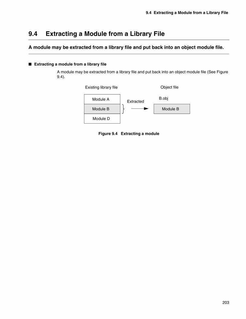
9.4 Extracting a Module from a Library File
203
9.4 Extracting a Module from a Library File
A module may be extracted from a library file and put back into an object module file.
� Extracting a module from a library file
A module may be extracted from a library file and put back into an object module file (See Figure 9.4).
Figure 9.4 Extracting a module
Module A
Module B
Module D
Existing library file
Module B
Object file
ExtractedB.obj

CHAPTER 9 SPECIFICATIONS OF A LIBRARIAN
204
9.5 Deleting Debugging Information of a Library
An object module registered with a debugging information block in a library may be re-registered without it.
� Deleting debugging information
An object module registered with a debugging information block in a library may be re-registered without it (See Figure 9.5).
Figure 9.5 Deleting debugging information
LHD LHDLMD1LMD2LMD3
LMD1LMD2LMD3
LED1LED2LED3
LED1LED2LED3
OM1 OM1OM1 debugging information OM2
OM2 OM3OM3 LTR
OM3 debugging information OM1 and OM3 registered with a debugging information block may be re-registered with-out it.
LTR
9.6 Checking and Displaying the Contents of a Library File
205
9.6 Checking and Displaying the Contents of a Library File
The following two items are checked.• Whether an unsolved external reference symbol exists in a library• Whether a module with debugging information existsAdditionally, this function provides you with information such as the date and time ofcreating and updating a library file and registering a module and the names of externaldefinition symbols defined in each module.
� Checking the contents of a library file
The following two items may be checked.
❍ Whether an unsolved external reference symbol exists in a library
A linker, when a module taken in from a library contains an external reference symbol, first searches for a defined symbol in the same library file.
Therefore, it is recommended that whenever an external reference symbol exists in a module in a library file, the module containing the concerned external definition symbol should be registered in the same library file.
The program checks the correspondence between external reference and defined symbols in a library file. If any undefined reference symbols remains, It outputs a diagnostic message.
❍ Whether a module with debugging information exists
If an object module with debugging information is contained, a diagnostic message is output.
If a module to be registered with the -g optionspecification in a library file contains debugging information, it is registered in the library with the debugging information unremoved.
The above function is provided so that a module registered in a library may be debugged. However, after the operation check, the debugging information will no longer be required.
� Displaying the contents of a library file
The module and external definition symbol information of a library file is edited and output to a list file and the standard output.
The list provides information such as: the date and time a library file was created and updated, when a module was registered, and the name of an external definition symbol defined in each module..
For the contents of display, see Chapter 11, “List Formats of a Librarian.”
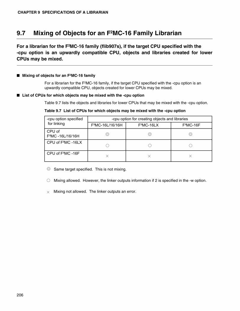
CHAPTER 9 SPECIFICATIONS OF A LIBRARIAN
206
9.7 Mixing of Objects for an F2MC-16 Family Librarian
For a librarian for the F2MC-16 family (flib907s), if the target CPU specified with the -cpu option is an upwardly compatible CPU, objects and libraries created for lowerCPUs may be mixed.
� Mixing of objects for an F2MC-16 family
For a librarian for the F2MC-16 family, if the target CPU specified with the -cpu option is an upwardly compatible CPU, objects created for lower CPUs may be mixed.
� List of CPUs for which objects may be mixed with the -cpu option
Table 9.7 lists the objects and libraries for lower CPUs that may be mixed with the -cpu option.
Table 9.7 List of CPUs for which objects may be mixed with the -cpu option
Same target specified. This is not mixing.
Mixing allowed. However, the linker outputs information if 2 is specified in the -w option.
Mixing not allowed. The linker outputs an error.
-cpu option specified for linking
-cpu option for creating objects and librariesF²MC-16L/16/16H F²MC-16LX F²MC-16F
CPU of F²MC -16L/16/16H
CPU of F²MC -16LX
CPU of F²MC -16F

207
CHAPTER 10 OPTIONS A LIBRARIAN
Chapter 10 describes the syntax, parameters, and precautions for options of alibrarian.
10.1 List of Options of a Librarian
10.2 Details of Options of a Librarian

CHAPTER 10 OPTIONS A LIBRARIAN
208
10.1 List of Options of a Librarian
Options are provided to specify the operations of a librarian in detail.
� List of Options of a Librarian
The table below gives the option names and an overview of their functions.
For details on the parameters and functions required for an option, see the description on each option.
Table 10.1 List of options for a librarian
Function Option Remarks
Options for creating and editing a library
Adding (registering) a module -a
Replacing (registering) a module -r
Deleting a module -d
Extracting a module -x
Options for outputting a list
Specifying to output a list file -m
Specifying not to output a list file -Xm Default
Specifying to output detailed information of a list file
-dt s,d,r,a
Specifying the number of lines per page of a list -pl Default: 60
Specifying the number of columns per line of a list
-pw Default: 70
Options for searching and protecting a file
Creating a backup file -b
Inhibiting the creation of a backup file -Xb Default
Checking the contents of a library file -c
Optimizing the contents of a file -O
Other options Specifying to output debugging information -g
Specifying not to output debugging information -Xg
Specifying a target CPU -cpu need
Common options Specifying not to read a default option file -Xdof
Specifying to read an option file -f
Specifying to display help messages -help
Specifying to output the version and messages -V
Specifying not to output the version and messages
-XV Default
Specifying to display a termination message -cmsg
Specifying not to display a termination message -Xcmsg Default
Specifying to set the termination code to 1 when a warning occurs
-cwno
Specifying to set the termination code to 0 when a warning occurs
-Xcwno Default
10.2 Details of the Options of a Librarian
209
10.2 Details of the Options of a Librarian
Section 10.2 describes the options of a librarian.The options common throughout Linkagekit are described in Chapter 3, “CommonOptions”.
� Options for creating and editing a library
Details of the options for creating and editing a library are described in Sections 10.2.1, “Adding (registering) a module (-a)” through 10.2.4, “ Extracting a module (-x)”.
� Options for outputting a list
Details of the options for outputting a list are described in Sections 10.2.5, “Specifying to output a list file (-m)” through 10.2.9, “Specifying the number of columns per line of a list (-pw)”.
� Options for searching and protecting a file
Details of the options for searching and protecting a file are described in Sections 10.2.10, “Creating a backup file (-b)” through 10.2.13, “Optimizing the contents of a file (-O)”.
� Other options
Details of other options are described in Sections 10.2.14, “Specifying to output debugging information (-g)” through 10.2.16, “Specifying a target CPU (-cpu)”.

CHAPTER 10 OPTIONS A LIBRARIAN
210
10.2.1 Adding (Registering) a Module (-a)
Use the -a option to create a new library file or to add a module to an existing libraryfile.
� Adding (registering) a module(-a)
[Syntax]
[Parameter]
<Object module file name>Object module file name that the assembler has output
[Description]
Specify a file name for the module to be registered in a library file.
If the file name has no extension specified, the “.obj” extension is assigned.
If an already registered module has the same name as the one to be registered, an error message is output and the latter module is not registered.
If an external definition symbol with the same name exists, a module is not registered either.
To specify <Object module file name>, you may use a wild card.
[Example 1]
flib896s syslib.lib -a mod1.obj,mod2.obj,modx.obj
To register the object module files, mod1.obj, mod2.obj, and modx.obj in the library file, syslib.lib:
• If syslib.lib does not exist: Creating one
• If syslib.lib exists: Adding modules to it and re-registering it
[Example 2]
flib896s syslib -a “mod*.obj” -a chksw
The object module files with the extension .obj and the first three characters as mod in the current directory and chksw.obj are registered.
Note: Up to 65535 modules may be registered.When using a wildcard, you cannot specify <Object module file name>separated with commas. Specify them in multiple -a options as shown in thefollowing example.If a wildcard is specified, you are not supplied with an extension. Be sure tospecify an extension. For information on the expansion of a wildcard in a file name which depends onthe OS, see Appendix G, “Differences of Specifications Depending on the OS”.
- a < Object module file name > [ , ... ]

10.2 Details of the Options of a Librarian
211
10.2.2 Replacing (Registering) a Module (-r)
A module in an existing library file is replaced with a new module with the same name.
� Replacing (registering) a module (-r)
[Syntax]
[Parameter]
<Object module file name> An object module file name that the assembler has output
[Description]
If a module in the library file being edited has the same name as the one in the specified file, the former module is replaced. Otherwise, the specified module is registered.
If the file name has no extension specified, the “.obj” extension is assigned.
To specify <Object module file name>, you may use a wild card.
[Example 1]
flib911s s syslib.obj -r loadx.obj,loady.obj
The two modules in loadx.obj and loady.obj replaces those with the same names in the library file being edited.
If no module with the same name exists in the library file, the modules are added to the library file which is then re-registered.
[Example 2]
flib911s syslib.lib -r "load?.obj"
The object module files with the extension .obj and the first four characters as load followed by one arbitrary character in the current directory are replaced.
Note:When using a wildcard, you cannot specify <Object module file name>separated with commas. Specify them in multiple -r options.If a wildcard is specified, you are not supplied with an extension. Be sure tospecify an extension.For information on the expansion of a wildcard in a file name which depends onthe OS, see Appendix G, “Differences of Specifications Depending on the OS”.
- r < Object module file name > [ , ... ]
CHAPTER 10 OPTIONS A LIBRARIAN
212
10.2.3 Deleting a Module (-d)
An unnecessary module is deleted from a library file.
� Deleting a module (-d)
[Syntax]
[Parameter]
<Module name>Name of a module to be deleted
[Description]
The specified module is deleted from a library file.
Be sure to specify a module name, not a file name.
[Example]
flib911s syslib.lib -d inchar,outchar
Two modules, inchar and outchar are deleted from syslib.lib.
Note:Although you may specify a module name using a pseudo instruction, use thesame name for an object module file and a module unless absolutely necessary.Using different names for them will cause an error when editing a library.To specify the same name for a file and a module, use a name consisting only ofalphanumeric characters and underscores. To check the module name, use the list output option (-m) to refer to the modulename that is output in the beginning of a list file.
- d < Module name > [ , ... ]
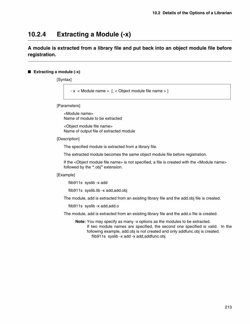
10.2 Details of the Options of a Librarian
213
10.2.4 Extracting a Module (-x)
A module is extracted from a library file and put back into an object module file beforeregistration.
� Extracting a module (-x)
[Syntax]
[Parameters]
<Module name>Name of module to be extracted
<Object module file name>Name of output file of extracted module
[Description]
The specified module is extracted from a library file.
The extracted module becomes the same object module file before registration.
If the <Object module file name> is not specified, a file is created with the <Module name> followed by the “.obj” extension.
[Example]
flib911s syslib -x add
flib911s syslib.lib -x add,add.obj
The module, add is extracted from an existing library file and the add.obj file is created.
flib911s syslib -x add,add.o
The module, add is extracted from an existing library file and the add.o file is created.
Note: You may specify as many -x options as the modules to be extracted. If two module names are specified, the second one specified is valid. In thefollowing example, add.obj is not created and only addfunc.obj is created.
flib911s syslib -x add -x add,addfunc.obj
- x < Module name > [, < Object module file name > ]

CHAPTER 10 OPTIONS A LIBRARIAN
214
10.2.5 Specifying to Output a List File (-m)
Module names and external definition symbol names registered in a library file areoutput as the information list.
� Specifying to output a list file (-m)
[Syntax]
[Parameter]
<List file name>Specify the file name of the librarian list to be output.
Specify a hyphen (-) to output the list in the standard output.
[Description]
Module names and external definition symbol names registered in a library file are output as the information list.
If the <List file name> has no extension specified, “.mp2” is added to it.
This option allows you to output only the information of module names registered. To display more detailed information, use the -dt option described later.
The list contents show the status when the librarian is terminated.
If no other option related to editing is provided, the contents of the specified library file is listed.
If you want to check the contents of a library file on the screen without storing it in a list, specify a hyphen in the parameter.
[Example 1]
flib911s syslib.lib -m libx.mp2
The module name list registered in syslib.lib is output to libx.mp2.
[Example 2]
flib911s syslib -a obj1,obj2 -m libx.lis
The contents of syslib.lib created after the obj1.obj and obj2.obj modules are added are output to libx.lis.
[Example 3]
flib911s syslib -m -
The module name list registered in syslib.lib is output to the standard output.
- m { < List file name > | - }

10.2 Details of the Options of a Librarian
215
10.2.6 Specifying not to Output a List File (-Xm)
This specification inhibits a librarian from outputting a list file.
� Specifying not to output a list file (-Xm)
[Syntax]
[Parameter]
None
[Description]
This specification inhibits the output of a list file.
Specifying the -Xm option after the -m option disables the -m option.
[Example]
flib911s syslib.lib -m libx.mp2 -Xm
The list file is not created.
- Xm

CHAPTER 10 OPTIONS A LIBRARIAN
216
10.2.7 Specifying to Output Detailed Information of a List File (-dt)
The -m option specifies outputting the list but only displays the list of registeredmodule names.Use the -dt option to obtain information on sections and external symbols for eachmodule registered in a library, or to obtain information on external definitions andexternal reference symbols for the entire library.
[Syntax]
[Parameter]
<Information type>s : Outputs a section name and its size for each module.
d : Outputs external definition symbols for each module.
r : Outputs external reference symbols for each module.
a : Outputs for the entire library external definition symbols and external reference symbolsyet unsolved in the library.
[Description]
If this option is not specified, only the registered module names are output in a list file. This option is used to obtain more detailed information.
The <Information type> must always be specified.
The <Information type> may be specified by listing multiple key words separated with commas.
If the -m option is not specified, this option is invalid.
[Example 1]
flib911s syslib.lib -m libx.mp2 -dt r,s
The list containing external reference symbols and section names is output to libx.mp2.
[Example 2]
flib911s syslib -m libx.lis -dt s,d,r,a
All the information that a librarian can output is output to libx.lis.
- dt < Information type > [ , < Information type > ] ...
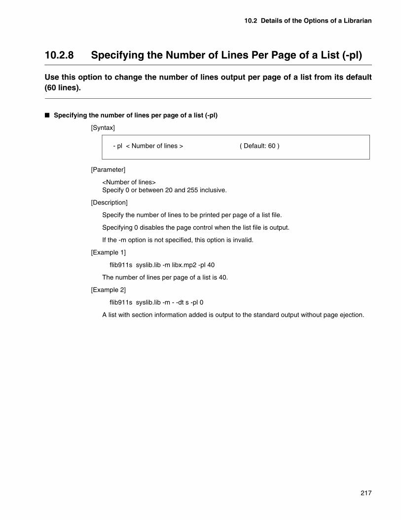
10.2 Details of the Options of a Librarian
217
10.2.8 Specifying the Number of Lines Per Page of a List (-pl)
Use this option to change the number of lines output per page of a list from its default(60 lines).
� Specifying the number of lines per page of a list (-pl)
[Syntax]
[Parameter]
<Number of lines>Specify 0 or between 20 and 255 inclusive.
[Description]
Specify the number of lines to be printed per page of a list file.
Specifying 0 disables the page control when the list file is output.
If the -m option is not specified, this option is invalid.
[Example 1]
flib911s syslib.lib -m libx.mp2 -pl 40
The number of lines per page of a list is 40.
[Example 2]
flib911s syslib.lib -m - -dt s -pl 0
A list with section information added is output to the standard output without page ejection.
- pl < Number of lines > ( Default: 60 )
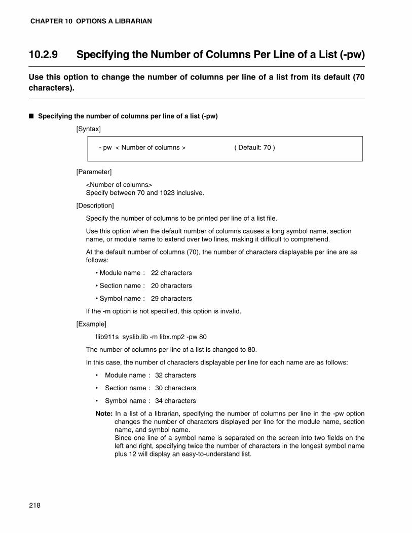
CHAPTER 10 OPTIONS A LIBRARIAN
218
10.2.9 Specifying the Number of Columns Per Line of a List (-pw)
Use this option to change the number of columns per line of a list from its default (70characters).
� Specifying the number of columns per line of a list (-pw)
[Syntax]
[Parameter]
<Number of columns>Specify between 70 and 1023 inclusive.
[Description]
Specify the number of columns to be printed per line of a list file.
Use this option when the default number of columns causes a long symbol name, section name, or module name to extend over two lines, making it difficult to comprehend.
At the default number of columns (70), the number of characters displayable per line are as follows:
• Module name : 22 characters
• Section name : 20 characters
• Symbol name : 29 characters
If the -m option is not specified, this option is invalid.
[Example]
flib911s syslib.lib -m libx.mp2 -pw 80
The number of columns per line of a list is changed to 80.
In this case, the number of characters displayable per line for each name are as follows:
• Module name : 32 characters
• Section name : 30 characters
• Symbol name : 34 characters
Note: In a list of a librarian, specifying the number of columns per line in the -pw optionchanges the number of characters displayed per line for the module name, sectionname, and symbol name. Since one line of a symbol name is separated on the screen into two fields on theleft and right, specifying twice the number of characters in the longest symbol nameplus 12 will display an easy-to-understand list.
- pw < Number of columns > ( Default: 70 )
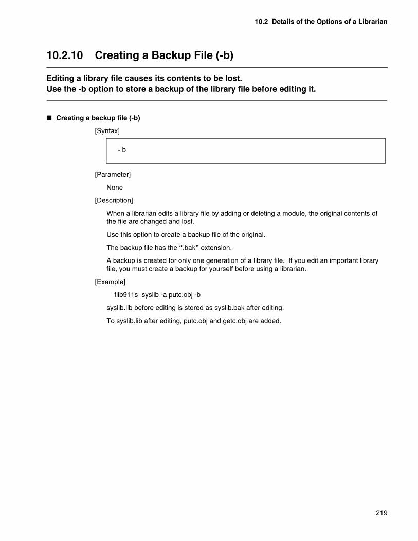
10.2 Details of the Options of a Librarian
219
10.2.10 Creating a Backup File (-b)
Editing a library file causes its contents to be lost.Use the -b option to store a backup of the library file before editing it.
� Creating a backup file (-b)
[Syntax]
[Parameter]
None
[Description]
When a librarian edits a library file by adding or deleting a module, the original contents of the file are changed and lost.
Use this option to create a backup file of the original.
The backup file has the “.bak” extension.
A backup is created for only one generation of a library file. If you edit an important library file, you must create a backup for yourself before using a librarian.
[Example]
flib911s syslib -a putc.obj -b
syslib.lib before editing is stored as syslib.bak after editing.
To syslib.lib after editing, putc.obj and getc.obj are added.
- b

CHAPTER 10 OPTIONS A LIBRARIAN
220
10.2.11 Inhibiting the Creation of a Backup File (-Xb)
Use the -Xb option to cancel the -b option used to obtain a backup.
� Inhibiting the creation of a backup file (-Xb)
[Syntax]
[Parameter]
None
[Description]
By default, a librarian does not create a backup for the library file to be edited. This is the same as specifying the -Xb option.
Specify this option to nullify the -b option when it is specified.
[Example]
All of the following three specifications result in the same processing.
flib911s syslib -a putc.obj,getc.objflib911s syslib -a putc.obj,getc.obj -Xbflib911s syslib -b -a putc.obj,getc.obj -Xb
syslib.lib before editing is deleted after editing.
To syslib.lib after editing, putc.obj and getc.obj are added.
- Xb ( Default )

10.2 Details of the Options of a Librarian
221
10.2.12 Checking the Contents of a Library File (-c)
Use this option to briefly check the contents of a library file. The following two itemsare checked.
� Checking the contents of a library file (-c)
[Syntax]
[Parameter]
None
[Description]
The following two items are checked.
❍ Whether an unsolved external reference symbol exists in the library
A linker, when a module taken in from a library contains an external reference symbol, firsttries to solve the symbol in the same library file, assuming that a module containing adefined symbol exists in the same library file.
The program checks the correspondence between external reference and definedsymbols in a library file. If any external reference symbols without the correspondingexternal definition symbol is contained, it outputs a message.
❍ Whether a module with debugging information exists
If a module to be registered with the -g option specification in a library file containsdebugging information, it is registered in the library with the debugging informationunremoved.
The above function is provided so that a module registered in a library may be debugged.However, after the operation check, the debugging information will no longer be required.
The program checks whether a module with debugging information is registered in alibrary and, if so, outputs a message.
[Example]
flib911s syslib.lib -c
The contents of syslib.lib are checked.
Note: This option cannot be specified with other options. Specify this option alone as shown in the following example.
- c

CHAPTER 10 OPTIONS A LIBRARIAN
222
10.2.13 Optimizing the Contents of a File (-O)
Any debugging information contained in an object module registered in a library isremoved.
� Optimizing the contents of a file (-O)
[Syntax]
[Parameter]
None
[Description]
An object module registered with a debugging information block in a library is re-registered without it.
Since debugging information occupies a very large part of an object module file, you can make a library file significantly smaller by deleting the debugging information.
[Example]
flib911s syslib -O
Debugging information is deleted from the syslib.lib file.
Note: This optimization option cannot be specified with other options. Specify this option alone as shown in the following example.
- O
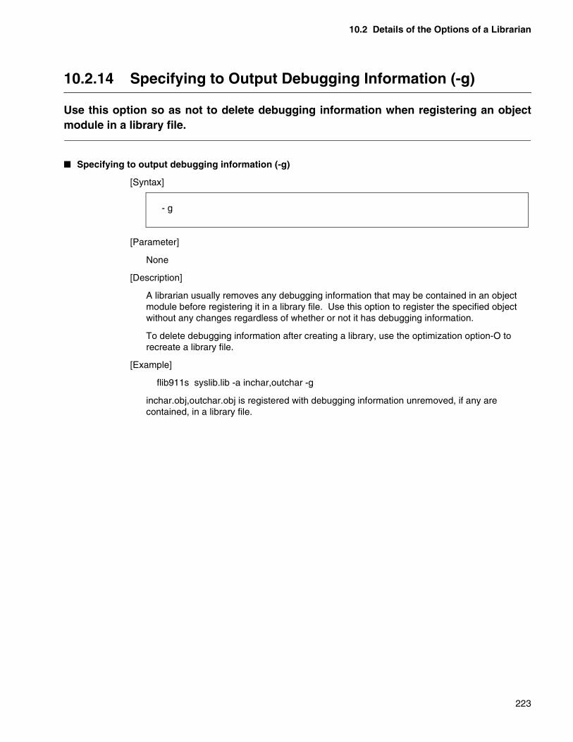
10.2 Details of the Options of a Librarian
223
10.2.14 Specifying to Output Debugging Information (-g)
Use this option so as not to delete debugging information when registering an objectmodule in a library file.
� Specifying to output debugging information (-g)
[Syntax]
[Parameter]
None
[Description]
A librarian usually removes any debugging information that may be contained in an object module before registering it in a library file. Use this option to register the specified object without any changes regardless of whether or not it has debugging information.
To delete debugging information after creating a library, use the optimization option-O to recreate a library file.
[Example]
flib911s syslib.lib -a inchar,outchar -g
inchar.obj,outchar.obj is registered with debugging information unremoved, if any are contained, in a library file.
- g
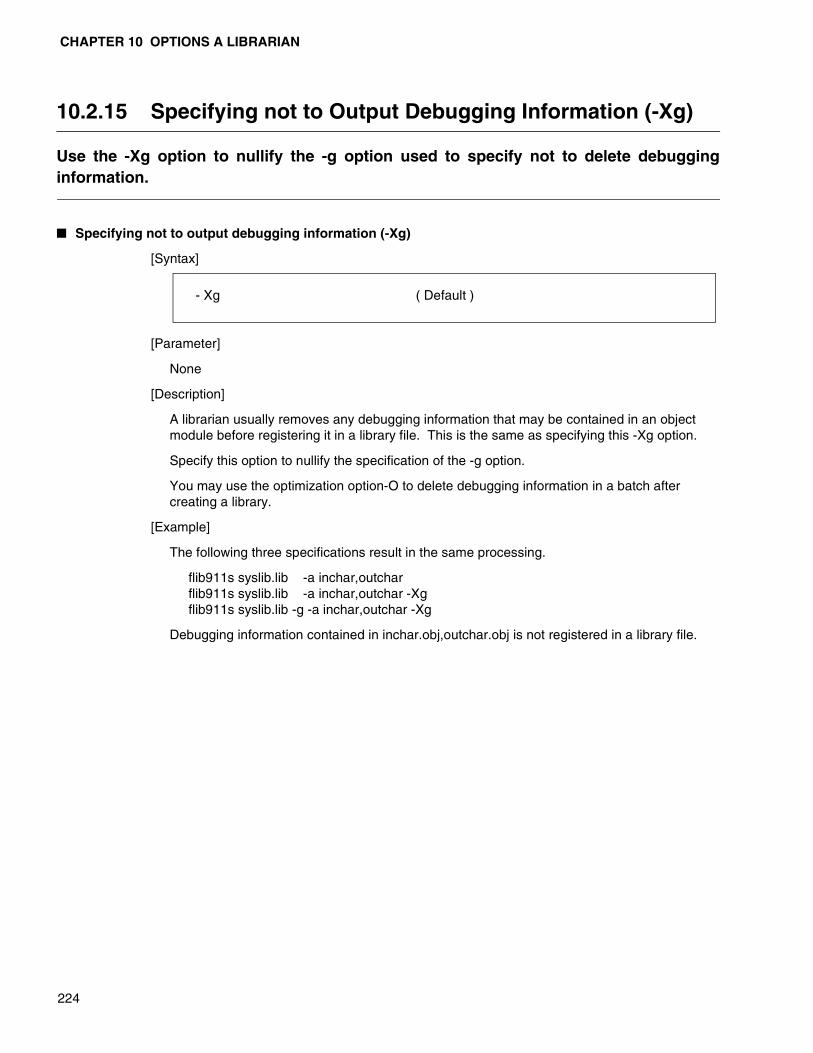
CHAPTER 10 OPTIONS A LIBRARIAN
224
10.2.15 Specifying not to Output Debugging Information (-Xg)
Use the -Xg option to nullify the -g option used to specify not to delete debugginginformation.
� Specifying not to output debugging information (-Xg)
[Syntax]
[Parameter]
None
[Description]
A librarian usually removes any debugging information that may be contained in an object module before registering it in a library file. This is the same as specifying this -Xg option.
Specify this option to nullify the specification of the -g option.
You may use the optimization option-O to delete debugging information in a batch after creating a library.
[Example]
The following three specifications result in the same processing.
flib911s syslib.lib -a inchar,outcharflib911s syslib.lib -a inchar,outchar -Xgflib911s syslib.lib -g -a inchar,outchar -Xg
Debugging information contained in inchar.obj,outchar.obj is not registered in a library file.
- Xg ( Default )

10.2 Details of the Options of a Librarian
225
10.2.16 Specifying a Target CPU (-cpu)
Use this option to specify a target CPU.Use an MB number to specify a target CPU of the programs to be combined into alibrary file.
[Syntax]
[Parameter]
<MB number>MB number of a target CPU
[Description]
A target CPU of the programs to be combined into a library file is specified using an MB number.
[Example]
flib907s syslib.lib -a inchar,outchar -cpu MB90600Aflib907s syslib.lib -a inchar,outchar -cpu MB90700
Note: To create a library, you must specify a target CPU using this option. This option may not be omitted.
- cpu < MB number >

226

227
CHAPTER 11 LIST FORMATS OF A LIBRARIAN
Chapter 11 describes the configuration of a list file of a librarian.
11.1 Contents of Information in a List File
11.2 List of Module Names
11.3 Detailed Information of a Module
11.4 External Defined and Reference Symbol Information in a Library
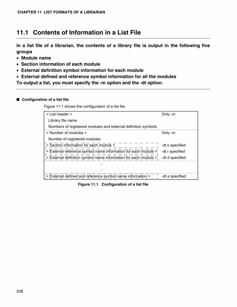
CHAPTER 11 LIST FORMATS OF A LIBRARIAN
228
11.1 Contents of Information in a List File
In a list file of a librarian, the contents of a library file is output in the following fivegroups• Module name• Section information of each module• External definition symbol information for each module• External defined and reference symbol information for all the modulesTo output a list, you must specify the -m option and the -dt option.
� Configuration of a list file
Figure 11.1 Configuration of a list file
Figure 11.1 shows the configuration of a list file.
< List header > Only -m Library file name Numbers of registered modules and external definition symbols< Number of modules > Only -m Number of registered modules< Section information for each module > -dt s specified< External reference symbol name information for each module > -dt r specified< External definition symbol name information for each module > -dt d specified
::
< External defined and reference symbol name information > -dt a specified
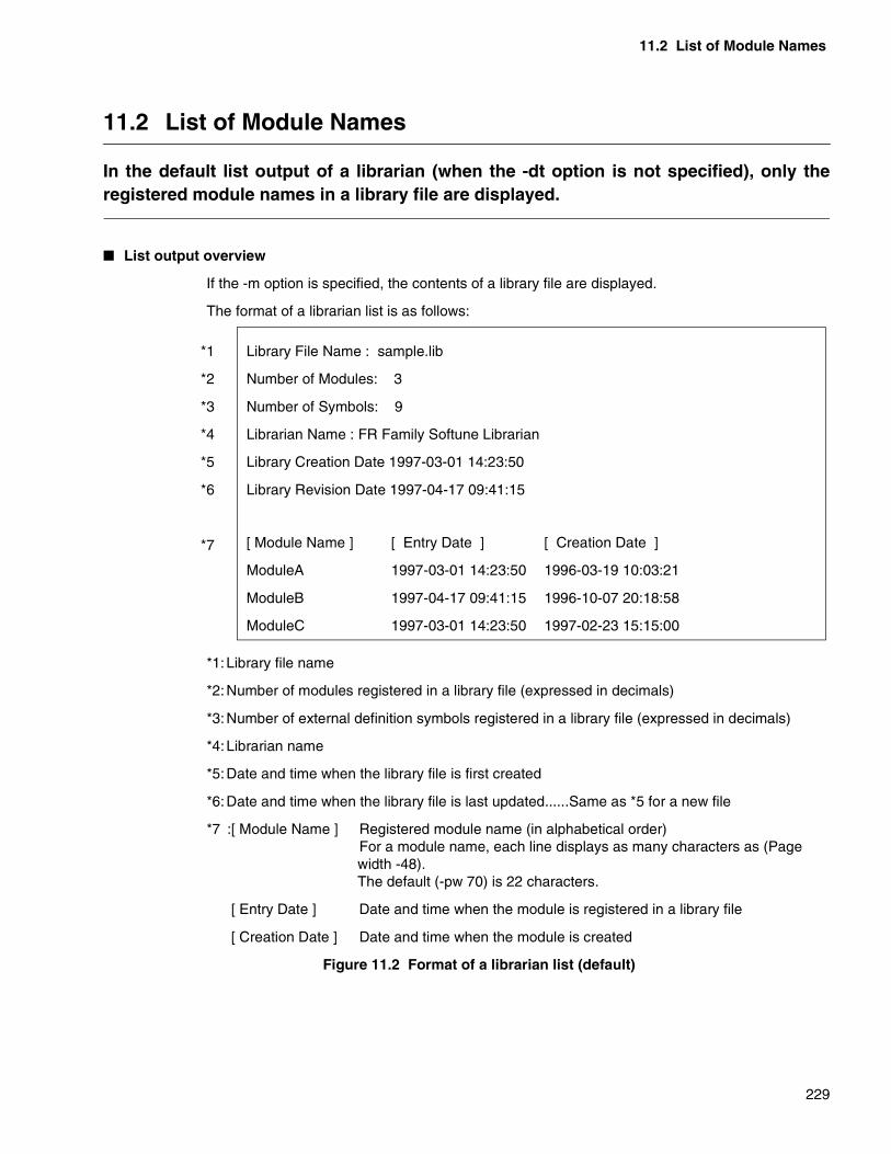
11.2 List of Module Names
229
11.2 List of Module Names
In the default list output of a librarian (when the -dt option is not specified), only theregistered module names in a library file are displayed.
� List output overview
If the -m option is specified, the contents of a library file are displayed.
The format of a librarian list is as follows:
*1:Library file name
*2:Number of modules registered in a library file (expressed in decimals)
*3:Number of external definition symbols registered in a library file (expressed in decimals)
*4:Librarian name
*5:Date and time when the library file is first created
*6:Date and time when the library file is last updated......Same as *5 for a new file
*7 :[ Module Name ] Registered module name (in alphabetical order)For a module name, each line displays as many characters as (Page width -48).The default (-pw 70) is 22 characters.
[ Entry Date ] Date and time when the module is registered in a library file
[ Creation Date ] Date and time when the module is created
Figure 11.2 Format of a librarian list (default)
Library File Name : sample.lib
Number of Modules: 3
Number of Symbols: 9
Librarian Name : FR Family Softune Librarian
Library Creation Date 1997-03-01 14:23:50
Library Revision Date 1997-04-17 09:41:15
*1
*2
*3
*4
*5
*6
*7 [ Module Name ] [ Entry Date ] [ Creation Date ]
ModuleA 1997-03-01 14:23:50 1996-03-19 10:03:21
ModuleB 1997-04-17 09:41:15 1996-10-07 20:18:58
ModuleC 1997-03-01 14:23:50 1997-02-23 15:15:00
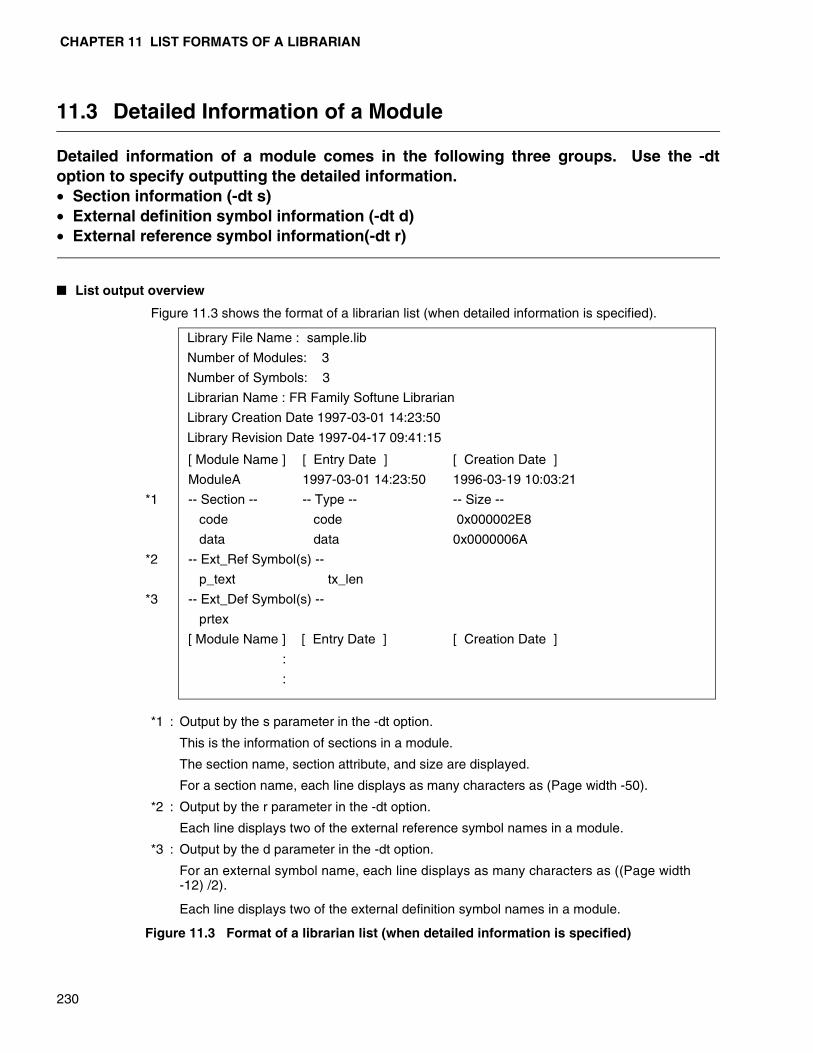
CHAPTER 11 LIST FORMATS OF A LIBRARIAN
230
11.3 Detailed Information of a Module
Detailed information of a module comes in the following three groups. Use the -dtoption to specify outputting the detailed information.• Section information (-dt s)• External definition symbol information (-dt d)• External reference symbol information(-dt r)
� List output overview
Figure 11.3 shows the format of a librarian list (when detailed information is specified).
*1 : Output by the s parameter in the -dt option.
This is the information of sections in a module.
The section name, section attribute, and size are displayed.
For a section name, each line displays as many characters as (Page width -50).
*2 : Output by the r parameter in the -dt option.
Each line displays two of the external reference symbol names in a module.
*3 : Output by the d parameter in the -dt option.
For an external symbol name, each line displays as many characters as ((Page width -12) /2).
Each line displays two of the external definition symbol names in a module.
Figure 11.3 Format of a librarian list (when detailed information is specified)
Library File Name : sample.lib
Number of Modules: 3
Number of Symbols: 3
Librarian Name : FR Family Softune Librarian
Library Creation Date 1997-03-01 14:23:50
Library Revision Date 1997-04-17 09:41:15
*1
*2
*3
[ Module Name ] [ Entry Date ] [ Creation Date ]
ModuleA 1997-03-01 14:23:50 1996-03-19 10:03:21
-- Section -- -- Type -- -- Size --
code code 0x000002E8
data data 0x0000006A
-- Ext_Ref Symbol(s) --
p_text tx_len
-- Ext_Def Symbol(s) --
prtex
[ Module Name ] [ Entry Date ] [ Creation Date ]
:
:
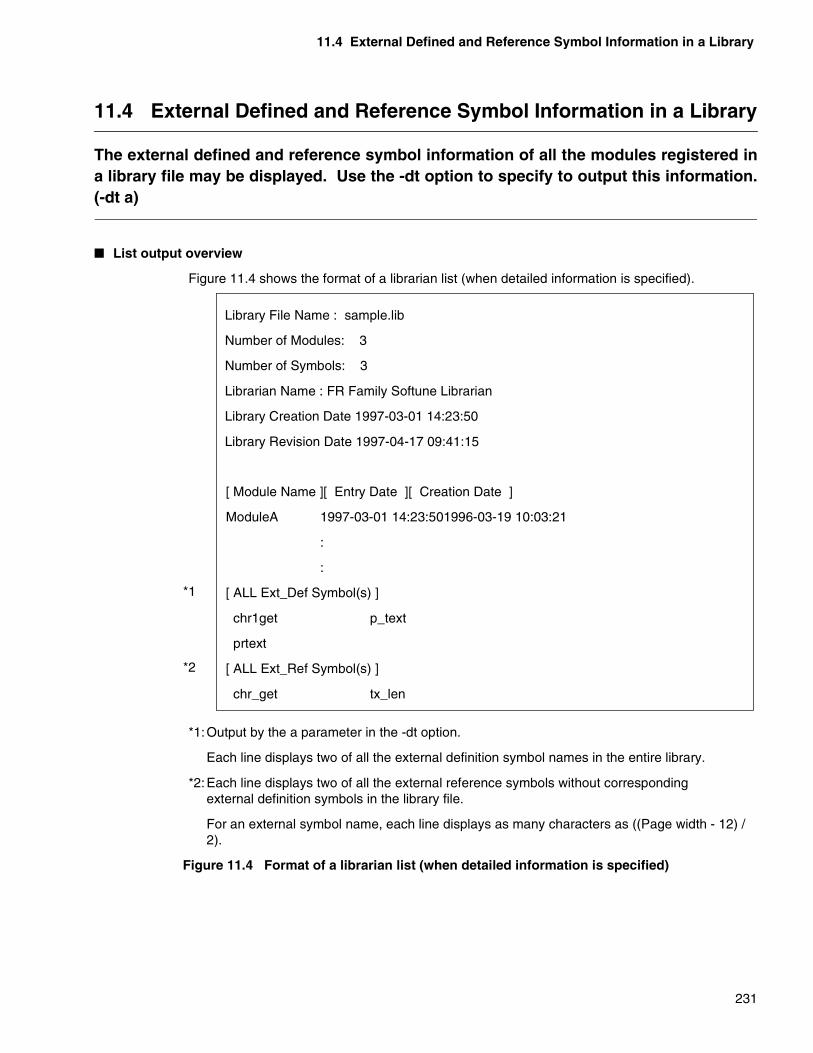
11.4 External Defined and Reference Symbol Information in a Library
231
11.4 External Defined and Reference Symbol Information in a Library
The external defined and reference symbol information of all the modules registered ina library file may be displayed. Use the -dt option to specify to output this information.(-dt a)
� List output overview
Figure 11.4 shows the format of a librarian list (when detailed information is specified).
*1:Output by the a parameter in the -dt option.
Each line displays two of all the external definition symbol names in the entire library.
*2:Each line displays two of all the external reference symbols without correspondingexternal definition symbols in the library file.
For an external symbol name, each line displays as many characters as ((Page width - 12) / 2).
Figure 11.4 Format of a librarian list (when detailed information is specified)
Library File Name : sample.lib
Number of Modules: 3
Number of Symbols: 3
Librarian Name : FR Family Softune Librarian
Library Creation Date 1997-03-01 14:23:50
Library Revision Date 1997-04-17 09:41:15
*1
*2
[ Module Name ][ Entry Date ][ Creation Date ]
ModuleA 1997-03-01 14:23:501996-03-19 10:03:21
:
:
[ ALL Ext_Def Symbol(s) ]
chr1get p_text
prtext
[ ALL Ext_Ref Symbol(s) ]
chr_get tx_len

232
MEMO

233
CHAPTER 12 RESTRICTIONS AND QUESTIONS AND ANSWERS ON A LIBRARIAN
Chapter 12 covers the restrictions and questions and answers on using a librarian.
12.1 Restrictions on a Librarian
12.2 Questions and Answers on Using a Librarian
CHAPTER 12 RESTRICTIONS AND QUESTIONS AND ANSWERS ON A LIBRARIAN
234
12.1 Restrictions on a Librarian
Section 12.1 describes restrictions on using a librarian, such as those on the numberof modules and external symbols that can be registered in a library file and otherprecautions.
� Restrictions on a librarian
There are two restrictions on using a librarian:
• Number of modules that can be registered in a library file: 65535 maximum
• Number of external definition symbols that can be registered in a library file: 65535maximum
� Precautions on the required disk space
Before editing an existing library file and creating a backup file, check that sufficient disk space is available to store the new library file and the existing library.
� Precautions on specifying options
Specify the options for checking the contents of a library file (-c) and optimizing the contents of a file (-O) alone, respectively.
These options may not be specified together with other options.
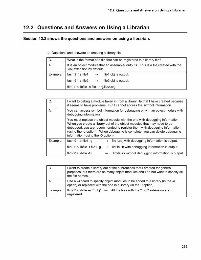
12.2 Questions and Answers on Using a Librarian
235
12.2 Questions and Answers on Using a Librarian
Section 12.2 shows the questions and answers on using a librarian.
❍ Questions and answers on creating a library file
Q. What is the format of a file that can be registered in a library file?
A. It is an object module that an assembler outputs. This is a file created with the .obj extension by default.
Example. fasm911s file1 → file1.obj is output.
fasm911s file2 → file2.obj is output.
flib911s libfile -a file1.obj,file2.obj
Q. I want to debug a module taken in from a library file that I have created because it seems to have problems. But I cannot access the symbol information.
A. You can access symbol information for debugging only in an object module with debugging information.
You must replace the object module with the one with debugging information. When you create a library out of the object modules that may need to be debugged, you are recommended to register them with debugging information (using the -g option). When debugging is complete, you can delete debugging information (using the -0 option).
Example. fasm911s file1 -g → file1.obj with debugging information is output.
flib911s libfile -r file1 -g → libfile.lib with debugging information is output.
flib911s libfile -O → libfile.lib without debugging information is output.
Q. I want to create a library out of the subroutines that I created for general purposes, but there are so many object modules and I do not want to specify all the file names.
A. Use a wildcard to specify object modules to be added to a library (in the -a option) or replaced with the one in a library (in the -r option).
Example. flib911s libfile -a “*.obj” → All the files with the “.obj” extension are registered.

CHAPTER 12 RESTRICTIONS AND QUESTIONS AND ANSWERS ON A LIBRARIAN
236
Q. I forgot what is contained in a library file that I created a while ago. How can I find what are the modules registered in it?
A. Use the -m option to see what is contained in a library file. Specify “-m File-name” to create a list file with the .mp2 extension by default. If the contents output by the -m option is not sufficient for you, use the -dt option together to obtain more detailed information.
Example. flib911s libfile -m libdoc → A list file, libdoc.mp2 is output.
flib911s libfile -m libdoc -dt a,s
→ A list file with detailed information, libdoc.mp2 is output.
Q. I want to check the contents of a library file but they need not be stored in a file. How can I simply display them on the screen?
A. Specify a hyphen (-) instead of a file name in the -m option to display the contents in the standard output.
Example flib911s libfile -m -
flib911s libfile -m - -dt a,s
flib911s libfile -a file3.obj -m -
Q. I output the contents of a library file into a list, but some long symbol names are displayed over two lines and difficult to comprehend. How can I evade this?
A. Use the -pw option to increase the number of columns to be displayed per line. It is 70 characters by default. If four characters are in the second line, add twice that number, i.e., eight to specify the number of columns as 78. Then the names will fit in one line.
Example. flib911s libfile -m libdoc -pw 80
Q. I replaced modules in a library file with the new ones only to realize later that I had registered some of them by mistake. Since I did not keep any backup for the library file before the replacement, I had a hard time restoring it.
A. A librarian allows you to create a backup file for one generation (with the “.bak” extension) using the -b option. Naturally, you are recommended to create a backup of a library before editing it. However, specify the -b option as required.
Example. flib911s libfile -r file1,file2 -d mod4 -b
237
PART 4 OBJECT FORMAT CONVERTERS
Part 4 describes the types of object format converters, list of options, functions, andconversions of object formats.
CHAPTER 13 PECIFICATIONS OF AN OBJECT FORMAT CONVERTER
CHAPTER 14 COMMON OPTIONS OF AN OBJECT FORMAT CONVERTER
CHAPTER 15 THE S FORMAT BINARY CONVERTER
CHAPTER 16 OPTIONS OF THE S FORMAT BINARY CONVERTER
CHAPTER 17 SPECIFICATIONS OF THE S FORMAT ADJUSTER
CHAPTER 18 OPTIONS OF THE S FORMAT ADJUSTER
CHAPTER 19 LOAD MODULE CONVERTERS
CHAPTER 20 OTHER CONVETERS
CHAPTER 21 RESTRICTIONS AND QUESTIONS AND ANSWERS ON AN OBJECT FORMAT CONVERTER

238
MEMO

239
CHAPTER 13 SPECIFICATIONS OF AN OBJEJECT FORMAT CONVERTER
Chapter 13 gives an overview and describes the types of object format converters.An object format converter is a tool used to convert an object format.
13.1 Overview of an Object Format Converter
13.2 Types of Converters
13.3 Executing an Object Format Converter
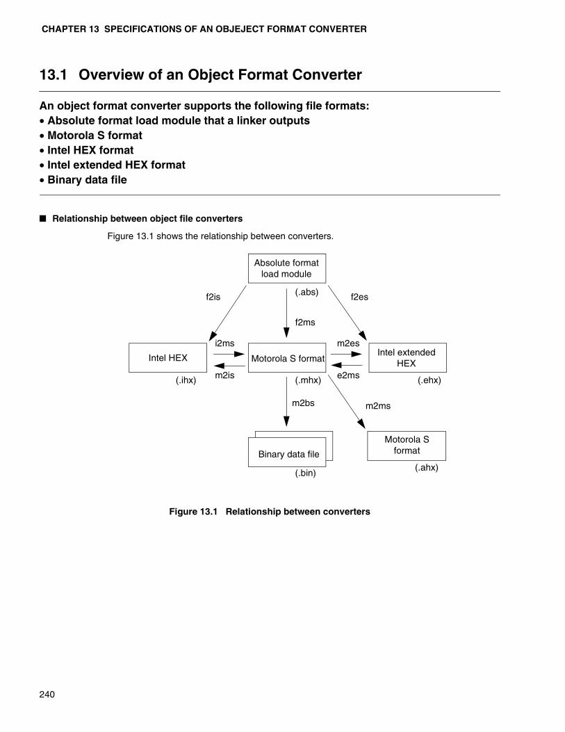
CHAPTER 13 SPECIFICATIONS OF AN OBJEJECT FORMAT CONVERTER
240
13.1 Overview of an Object Format Converter
An object format converter supports the following file formats:• Absolute format load module that a linker outputs• Motorola S format• Intel HEX format• Intel extended HEX format• Binary data file
� Relationship between object file converters
Figure 13.1 shows the relationship between converters.
Figure 13.1 Relationship between converters
Absolute formatload module
(.ihx)
(.abs) f2is
Motorola S formatIntel extended
HEXIntel HEX
Binary data file
(.mhx) (.ehx)
(.bin)(.ahx)
f2es
i2ms
m2is e2ms
m2es
m2bs
f2ms
m2ms
Motorola S format

13.2 Types of Converters
241
13.2 Types of Converters
The command for an object format converter is x2ys, where the x represents the objectformat of an input file and the y represents the object format of an output file.An alphabetic character assigned in the x and y format means one of the followingformats:• f: Absolute format load module that a linker outputs• m: Motorola S format• i: Intel HEX format• e: Intel extended HEX format• b: Binary data format
� S Format Binary Converter
An object file in the S format is converted to binary data (a memory image) and output into a file. For details, see Chapter 16, “Option of the S Format Binary Converter”.
� S Format Adjuster
The S Format Adjuster formats an object file in the S format. For details, see Chapter 18, “Options of the S Format Adjuster”.
� Types of load module converters
Use the commands in Table 13.2a to convert an object format.
Table 13.2a Conversions made by load module converters
� Types of other converters
Use the commands in Table 13.2b to convert an object format.
Table 13.2b Conversions made by other converters
Command name Conversion
f2ms Converts an absolute format load module into the Motorola S format
f2is Converts an absolute format load module into the Intel HEX format
f2es Converts an absolute format load module into the Intel extended HEX format
Command name Conversion
m2is Converts from the Motorola S format into the Intel HEX format
m2es Converts from the Motorola S format into the Intel extended HEX format
i2ms Converts an absolute format load module into the Intel extended HEX format
e2ms Converts from the Intel extended HEX format into the Motorola S format

CHAPTER 13 SPECIFICATIONS OF AN OBJEJECT FORMAT CONVERTER
242
13.3 Executing an Object Format Converter
Simply specify a command name followed by an input file name to execute an objectformat converter.
� Executing a command of an object format converter
Simply specify a command name followed by an input file name to execute the command.
The specified <Input file name> is processed as the x format and a file in the y format is created.
A converter uses the following extensions by default to identify an object format from a file name:
• Absolute format load module : .abs
• Motorola S format : .mhx, .ahx
• Intel HEX : .ihx
• Intel extended HEX : .ehx
• Binary data format : .bin
The -ran option is always required to execute the S Format Binary Converter. For details, see Section 16.2.1, “Specifying the output range (-ran).”
[Example]
f2ms sample
The absolute format load module that a linker outputs, sample.abs, is input and thesample.mhx file in the Motorola S format is output.
x2ys < Input file name > [ Option ]
243
CHAPTER 14 COMMON OPTIONS OF AN OBJECT FORMAT CONVERTER
Chapter 14 describes the common options of an object format converter in detail.
14.1 List of Common Options of an Object Format Converter
14.2 Changing an Output File Name (-o)
14.3 Padding (-p)
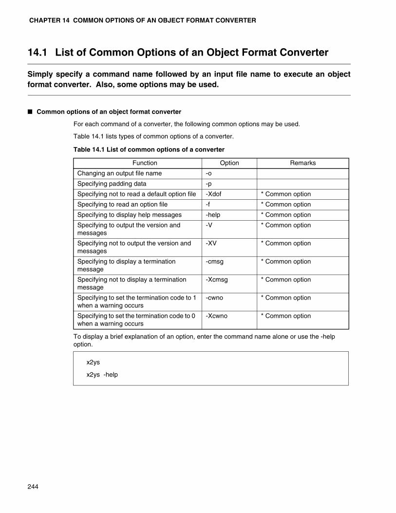
CHAPTER 14 COMMON OPTIONS OF AN OBJECT FORMAT CONVERTER
244
14.1 List of Common Options of an Object Format Converter
Simply specify a command name followed by an input file name to execute an objectformat converter. Also, some options may be used.
� Common options of an object format converter
For each command of a converter, the following common options may be used.
Table 14.1 lists types of common options of a converter.
Table 14.1 List of common options of a converter
To display a brief explanation of an option, enter the command name alone or use the -help option.
Function Option Remarks
Changing an output file name -o
Specifying padding data -p
Specifying not to read a default option file -Xdof * Common optionSpecifying to read an option file -f * Common optionSpecifying to display help messages -help * Common optionSpecifying to output the version and messages
-V * Common option
Specifying not to output the version and messages
-XV * Common option
Specifying to display a termination message
-cmsg * Common option
Specifying not to display a termination message
-Xcmsg * Common option
Specifying to set the termination code to 1 when a warning occurs
-cwno * Common option
Specifying to set the termination code to 0 when a warning occurs
-Xcwno * Common option
x2ys
x2ys -help

14.2 Changing an Output File name (-o)
245
14.2 Changing an Output File name (-o)
The directory in which to create an output file after conversion and the file name arechanged from the default.
� Changing an Output File name (-o)
[Syntax]
[Parameter]
<Object file name> Output file name
[Description]
Specify this option to change the output file name after conversion.
Specify this option with a path name to change also the output destination directory.
If this option is omitted, the output file name will be the same as the input file name. However, its extension will be changed to the default of one of the formats used after conversion.
If the extension is omitted in the <Object file name> specification, the default extension is added.
One of the following six default extensions is used for each format:
• Absolute format load module ...... .abs
• Motorola S format ...... .mhx
• Motorola S format (adjusted) ...... .ahx
• Intel HEX...... .ihx
• Intel extended HEX...... .ehx
• Binary data file ...... .bin
[Example 1]
f2ms ccp903 (Example of not using the -o option)
The absolute format load module ccp903.abs is input and ccp903.mhx in the Motorola S format is output. The following four examples are equivalent to the above.
f2ms ccp903.abs -o ccp903.mhx
f2ms ccp903.abs -o ccp903
f2ms ccp903 -o ccp903.mhx
f2ms ccp903 -o ccp903
-o < Object file name >
CHAPTER 14 COMMON OPTIONS OF AN OBJECT FORMAT CONVERTER
246
[Example 2]
f2ms ccp903 -o ccp903.hex
The output file name is changed to ccp903.hex.
[Example 3]
f2ms ccp903 -o ..\hex\ccp903m.hex
The current output destination directory is changed to ..\hex and the output file name to ccp903m.hex.
Note:If the -sp option is specified for S Format Binary Converter, the <Object file name> isevaluated differently. The <Object file name> is assumed to have no extension and anextension is unconditionally added to the file name specified in <Object file name>. For example, if “binary.bin” is specified as the object file name, the output file names willbe “binary.bin.b01”, “binary.bin.b02”, ..., “binary.bin.bxx”.

14.3 Padding (-p)
247
14.3 Padding (-p)
The specified range of addresses is padded with data of a specified value.With the S Format Binary Converter, the portion of an S format file containing no datais padded with data of a specified value.
� Padding (-p)
[Syntax]
[Parameters]
<Value> One-byte data
<Starting address> Starting address at which to set <Value>
* Not to be specified for the S Format Binary Converter or the S Format Adjuster
<Ending address> Ending address at which to set <Value>
* Not to be specified for the S Format Binary Converter or the S Format Adjuster
[Description]
The specified range of addresses is padded with data of a specified value.
Set only the <Value> for the S Format Binary Converter.
For the S Format Binary Converter, the portion of an S format file containing no data is padded with data of a specified value.
[Example 1]
f2ms ccp903 -p 0xEF,0x1FE4,0x1FFF
An absolute format load module is converted into the Motorola S format.
At this time, the data at the addresses 0x1FE4 through 0x1FFF is created as the 0xEF data and added to the end of a Motorola S format file.
[Example 2]
m2bs ccp903 -ran 0x0,0x1FFF -p 0xEF
The data at the addresses 0x0 through 0xFFF in the Motorola S format file is converted to a binary image.
At this time, the portion of an S format file containing no data is padded with data of 0xEF.
- p < Value > , < Starting address > , < Ending address >

248
MEMO

249
CHAPTER 15 THE S FORMAT BINARY CONVERTER
Chapter 15 describes the conversion formats of the S Format Binary Converter.
15.1 Specification of the S Format Binary Converter

CHAPTER 15 THE S FORMAT BINARY CONVERTER
250
15.1 Specification of the S Format Binary Converter
The S Format Binary Converter converts a file output in the Motorola S format to abinary data file.The S Format Binary Converter not only converts data to binary data but also supportsthe split mode in which to output data into multiple files.
� Overview of the S Format Binary Converter
An object file in the S format created by Linkagekit is converted by the S Format Binary Converter into binary data (memory image) and output into a file.
You may specify multiple input files (S format files). Additionally, binary data after conversion may be split for specified bytes and output into multiple files (hereafter called the split mode).
Note:The portion of an S format file containing no data is padded with 0xFF (default value). Thebinary data file to be output is the contents of memory that is output into a file withoutchanges.Use the padding option (-p) to pad with a specified value the portion of an S format filecontaining no data. For details on how to use this option, see Section 14.3, “Padding (-p)”.The default extension of an output binary file is .bin. In the split mode, the extension .bxx(xx is a two digit number (01 through 16)) is unconditionally added.
� Overview of the split mode
A split mode means that the memory image converted by S Format Binary Converter is split for specified bytes and output into multiple binary data file.
Figure 15.1 shows an overview of the split mode. In Figure 15.1, every byte of data is output in turns into two files. In the split mode, every specified byte of data may be output in turns into sixteen files maximum.
Use the -sp option to specify the split mode. For details on how to use the -sp option, see Section 16.2.2, “Specifying the split mode (-sp)”.
m2bs
(.mhx) (.bin)
Motorola
S format
file
Binary data
file
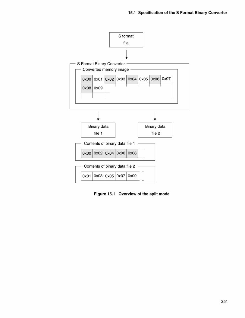
15.1 Specification of the S Format Binary Converter
251
Figure 15.1 Overview of the split mode
S format
file
S Format Binary ConverterConverted memory image
0x00
0x08
0x01
0x09
0x02 0x03 0x04 0x05 0x06 0x07
Binary data
file 1
Binary data
file 2
0x00 0x02 0x04 0x06 0x08
Contents of binary data file 2
0x01 0x03 0x05 0x07 0x09
Contents of binary data file 1

252
MEMO

253
CHAPTER 16 OPTIONS OF THE S FOREMAT BINARY CONVERTER
Chapter 16 describes options of the S Format Binary Converter.
16.1 Options of the S Format Binary Converter
16.2 Details on Options of the S Format Binary Converter

CHAPTER 16 OPTIONS OF THE S FOREMAT BINARY CONVERTER
254
16.1 Options of the S Format Binary Converter
Section 16.1 lists the option names and functions of the S Format Binary Converter.
� Options of the S Format Binary Converter
Table 16.1 lists options of the S Format Binary Converter.
Table 16.1 Options of the S Format Binary Converter
Function Option Remarks
Changing an output file name -o * Common option for a converter
Specifying padding data -p * Common option for a converter
Specifying the output range -ran
Specifying the split mode -sp
Specifying the inhibition of the split mode -Xsp
Specifying to create a map list file -m
Specifying not to create a map list file -Xm
Specifying not to read a default option file -Xdof * Common option
Specifying to read an option file -f * Common option
Specifying to display help messages -help * Common option
Specifying to output the version and messages -V * Common option
Specifying not to output the version and messages -XV * Common option
Specifying to display a termination message -cmsg * Common option
Specifying not to display a termination message -Xcmsg * Common option
Specifying to set the termination code to 1 when a
warning occurs-cwno * Common option
Specifying to set the termination code to 0 when a
warning occurs-Xcwno * Common option
16.2 Details on Options of the S Format Binary Converter
255
16.2 Details on Options of the S Format Binary Converter
Section 16.2 describes the options of the S Format Binary Converter.For information on the common options for Linkagekit, see Chapter 3, “CommonOptions”. For information on the common options for a converter, see Chapter 14,“Common Options for an Object Format Converter”.
� Specifying the output range (-ran)
This option specifies the range of an S format file to be converted to a binary image. For details, see Section 16.2.1, “Speciyfing the output range (-ran)”.
� Specifying the split mode (-sp)
This option specifies that a binary image is output in the split mode. For details, see Section 16.2.2, “Specifying the split mode (-sp)”.
� Specifying the inhibition of the split mode (-Xsp)
This option nullifies the split mode specification (-sp). For details, see Section 16.2.3, “Specifying the inhibition of the split mode (-Xsp)”.
� Specifying to create a map list file (-m)
This option specifies that conversion information is output in a list file. For details, see Section16.2.4, “Specifying to create a map list file (-m)”.
� Specifying not to create a map list file (-Xm)
This option nullifies the specification to create a map list file (-m). For details, see Section 16.2.5, “Specifying not to create a map list file (-Xm)”.
CHAPTER 16 OPTIONS OF THE S FOREMAT BINARY CONVERTER
256
16.2.1 Specifying the Output Range (-ran)
Use addresses to specify the range of an S format file to be converted to a binaryimage.This option must be specified for S Format Binary Converter.
� Specifying the output range (-ran)
[Syntax]
[Parameters]
<Starting address>Starting address
<Ending address>Ending address
[Description]
Use addresses to specify the range of an S format file to be converted to a binary image.
This option must be specified before converting.
Specify the starting and ending addresses between 0x0 and 0xFFFFFFFF inclusive.
The ending address may be omitted. If so, data as much as 64Kbytes from the starting address is converted to binary.
You cannot specify values that will make the conversion size more than 2Gbytes.
[Example 1]
m2bs sfmtfile.mhx (An example of not using the -ran option)
An error occurs because the output range is not specified.
[Example 2]
m2bs sfmtfile.mhx -ran 0xD000,0xFFFF
The data in sfmtfile.mhx at addresses 0xD000 through 0xFFFF is extracted and output into a binary image file.
[Example 3]
m2bs sfmtfile.mhx -ran 0xD000 (An example of not using the ending address)
The data in sfmfile.mhx as much as 64Kbytes from the address 0xD000 (0x0D000 through 0x1CFFF) is extracted and output into a binary image file.
[Example 4]
m2bs sfmtfile.mhx -ran 0xFFFF,0xD000
An error occurs because the specified ending address is smaller than the starting address.
[Example 5]
m2bs sfmtfile.mhx -ran (Example of omitting all the parameters)
An error occurs because the starting address is omitted.
- ran < Starting address > [ , < Ending address > ]
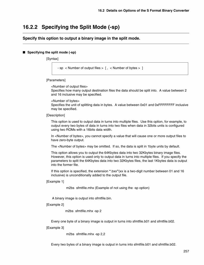
16.2 Details on Options of the S Format Binary Converter
257
16.2.2 Specifying the Split Mode (-sp)
Specify this option to output a binary image in the split mode.
� Specifying the split mode (-sp)
[Syntax]
[Parameters]
<Number of output files>Specifies how many output destination files the data should be split into. A value between 2 and 16 inclusive may be specified.
<Number of bytes>Specifies the unit of splitting data in bytes. A value between 0x01 and 0xFFFFFFFF inclusive may be specified.
[Description]
This option is used to output data in turns into multiple files. Use this option, for example, to output every two bytes of data in turns into two files when data in 32bits units is configured using two ROMs with a 16bits data width.
In <Number of bytes>, you cannot specify a value that will cause one or more output files to have zero-byte output.
The <Number of bytes> may be omitted. If so, the data is split in 1byte units by default.
This option allows you to output the 64Kbytes data into two 32Kbytes binary image files. However, this option is used only to output data in turns into multiple files. If you specify the parameters to split the 64Kbytes data into two 32Kbytes files, the last 1Kbytes data is output into the former file.
If this option is specified, the extension “.bxx”(xx is a two-digit number between 01 and 16 inclusive) is unconditionally added to the output file.
[Example 1]
m2bs sfmtfile.mhx (Example of not using the -sp option)
A binary image is output into sfmtfile.bin.
[Example 2]
m2bs sfmtfile.mhx -sp 2
Every one byte of a binary image is output in turns into sfmtfile.b01 and sfmtfile.b02.
[Example 3]
m2bs sfmtfile.mhx -sp 2,2
Every two bytes of a binary image is output in turns into sfmtfile.b01 and sfmtfile.b02.
- sp < Number of output files > [ , < Number of bytes > ]

CHAPTER 16 OPTIONS OF THE S FOREMAT BINARY CONVERTER
258
16.2.3 Specifying the Inhibition of the Split Mode (-Xsp)
The -Xsp option nullifies the split mode specification (-sp).
� Specifying the inhibition of the split mode (-Xsp)
[Syntax]
[Parameter]
None
[Description]
Specify this option to nullify the -sp specification.
This option needs not be specified in particular because it is the default.
[Example]
m2bs ccp903.mhx -ran 0xE000,0xFFFFm2bs cpp903.mhx -Xsp -ran 0xE000,0xFFFF
The default processing does not run in the split mode.The above specifications are equivalent.
m2bs -f option.file ccp903 -Xsp
You may sometimes want to temporarily change the specification in an option file when the option file is used to execute the program.
If the -sp option exists in option.file, there is no need to change the contents of option.file. Simply specify the -Xsp option on a command line to nullify the -sp option.
- Xsp

16.2 Details on Options of the S Format Binary Converter
259
16.2.4 Specifying to Create a Map List File (-m)
Use this option to output the information at the time of conversion into a map list file.
� Specifying to create a map list file (-m)
[Syntax]
[Parameter]
<Map list file name> Output map list file name
[Description]
Use this option to output information at the time of conversion into a map list file.
The information at the time of conversion is output into a map list file. The following information is output. Item (4) is output only if the -sp option is specified.
1)Input file name information
2)Output file name information
3)Output range information
4)Split unit information
5)Padding data value information
If the <Map list file> has no extension, the default extension “.mp3” is added.
[Example 1]
m2bs sfmtfile.mhx -ran 0x10000,0x1FFFF(Example of not specifying the -m option)
A map list file is not created because the -m option is not specified.
[Example 2]
m2bs sfmtfile.mhx -ran 0x10000,0x1FFFF -m logfile
The information at the time of conversion is output into logfile.mp3.
- m < Map list file name >
Contents of logfile.mp3
Input file :sfmtfile.mhxOutput file :sfmtfile.binConvert range :0x00010000 - 0x0001FFFFPadding data :0xFF

CHAPTER 16 OPTIONS OF THE S FOREMAT BINARY CONVERTER
260
[Example 3]
m2bs sfmtfile.mhx -ran 0x10000,0x1FFFF -m logfile -sp 2,2
The information at the time of conversion is output into logfile.mp3.Contents of logfile.mp3
Input file :sfmtfile.mhxOutput file :sfmtfile.b01
:sfmtfile.b02Convert range :0x00010000 - 0x0001FFFFSplit byte :2Padding data :0xFF
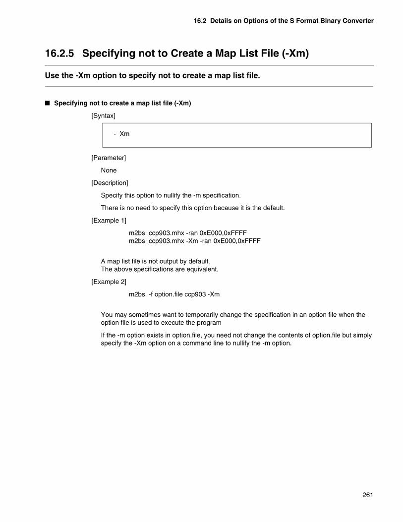
16.2 Details on Options of the S Format Binary Converter
261
16.2.5 Specifying not to Create a Map List File (-Xm)
Use the -Xm option to specify not to create a map list file.
� Specifying not to create a map list file (-Xm)
[Syntax]
[Parameter]
None
[Description]
Specify this option to nullify the -m specification.
There is no need to specify this option because it is the default.
[Example 1]
m2bs ccp903.mhx -ran 0xE000,0xFFFFm2bs ccp903.mhx -Xm -ran 0xE000,0xFFFF
A map list file is not output by default.The above specifications are equivalent.
[Example 2]
m2bs -f option.file ccp903 -Xm
You may sometimes want to temporarily change the specification in an option file when the option file is used to execute the program
If the -m option exists in option.file, you need not change the contents of option.file but simply specify the -Xm option on a command line to nullify the -m option.
- Xm

262
MEMO

263
CHAPTER 17 SPECIFICATIONS OF THE S FORMAT ADJUSTER
Chapter 17 describes the conversion formats of the S Format Adjuster.
17.1 Specifications of the S Format Adjuster

CHAPTER 17 SPECIFICATIONS OF THE S FORMAT ADJUSTER
264
17.1 Specifications of the S Format Adjuster
The S Format Adjuster sorts data created in the Motorola S format in the ascendingorder of addresses, and causes each of the records to contain the specified number ofdata.
� Overview of the S Format Adjuster
The S Format Adjuster causes each of the records in one file of the Motorola S format to contain the specified number of data to unify the format. Figure17.1 shows the concept of the S Format Adjuster.
Figure 17.1 Concept of the S Format AdjusterThe portion of an input S format file containing no data is padded with 0xFF (default value).
The output file is the contents of memory converted into the S format without changes.
Use the padding option (-p option) to pad the portion of an S format file containing no data with a specified value. For information on using this option, see Section 14.3, “Padding (-p).”
� Example of operation
Use this option to unify the lengths of data contained in one record if an existing S format file has records of varying lengths.
Motorola
S format
file
Motorola
S formatm2ms
(.mhx) (.ahx)
S007000054455354B8 S20CFF00000109572C160C2D2CEC S209FF0008020406080AD1 S20FFF000D020406080A0C0E1012141660 S20CFF00180109572C160C2D2CD4 S209FF0020020406080AB9 S20FFF0025020406080A0C0E1012141648 S20CFF00300109572C160C2D2CBC S209FF0038020406080AA1 S20FFF003D020406080A0C0E1012141630 S20CFF00480109572C160C2D2CA4 S209FF0050020406080A89 S20FFF0055020406080A0C0E1012141618 S804000000FB
Before conversion
S007000054455354B8S31500FF00000109572C160C2D2C020406080A020406B9S31500FF0010080A0C0E101214160109572C160C2D2C5BS31500FF0020020406080A020406080A0C0E1012141629S31500FF00300109572C160C2D2C020406080A02040689S31500FF0040080A0C0E101214160109572C160C2D2C2BS31500FF0050020406080A020406080A0C0E10121416F9S70500000000FA
S007000054455354B8 S31500FF00000109572C160C2D2C020406080A020406B9 S31500FF0010080A0C0E101214160109572C160C2D2C5B S31500FF0020020406080A020406080A0C0E1012141629 S31500FF00300109572C160C2D2C020406080A02040689 S31500FF0040080A0C0E101214160109572C160C2D2C2B S31500FF0050020406080A020406080A0C0E10121416F9 S70500000000FA
After conversion
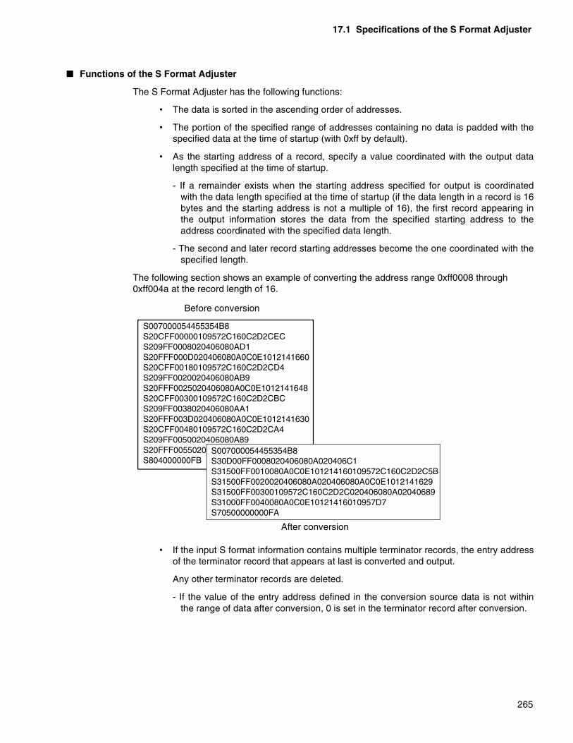
17.1 Specifications of the S Format Adjuster
265
� Functions of the S Format Adjuster
The S Format Adjuster has the following functions:
• The data is sorted in the ascending order of addresses.
• The portion of the specified range of addresses containing no data is padded with thespecified data at the time of startup (with 0xff by default).
• As the starting address of a record, specify a value coordinated with the output datalength specified at the time of startup.
- If a remainder exists when the starting address specified for output is coordinatedwith the data length specified at the time of startup (if the data length in a record is 16bytes and the starting address is not a multiple of 16), the first record appearing inthe output information stores the data from the specified starting address to theaddress coordinated with the specified data length.
- The second and later record starting addresses become the one coordinated with thespecified length.
The following section shows an example of converting the address range 0xff0008 through 0xff004a at the record length of 16.
• If the input S format information contains multiple terminator records, the entry addressof the terminator record that appears at last is converted and output.
Any other terminator records are deleted.
- If the value of the entry address defined in the conversion source data is not withinthe range of data after conversion, 0 is set in the terminator record after conversion.
S007000054455354B8 S20CFF00000109572C160C2D2CEC S209FF0008020406080AD1 S20FFF000D020406080A0C0E1012141660 S20CFF00180109572C160C2D2CD4 S209FF0020020406080AB9 S20FFF0025020406080A0C0E1012141648 S20CFF00300109572C160C2D2CBC S209FF0038020406080AA1 S20FFF003D020406080A0C0E1012141630 S20CFF00480109572C160C2D2CA4 S209FF0050020406080A89 S20FFF0055020406080A0C0E1012141618 S804000000FB
Before conversion
S007000054455354B8 S30D00FF0008020406080A020406C1 S31500FF0010080A0C0E101214160109572C160C2D2C5B S31500FF0020020406080A020406080A0C0E1012141629 S31500FF00300109572C160C2D2C020406080A02040689 S31000FF0040080A0C0E10121416010957D7 S70500000000FA
After conversion

266
MEMO

267
CHAPTER 18 OPTIONS OF THE S FORMAT ADJUSTER
Chapter 18 describes the options of S Format Adjuster.
18.1 List of Options of the S Format Adjuster
18.2 Details of Options of the S Format Adjuster
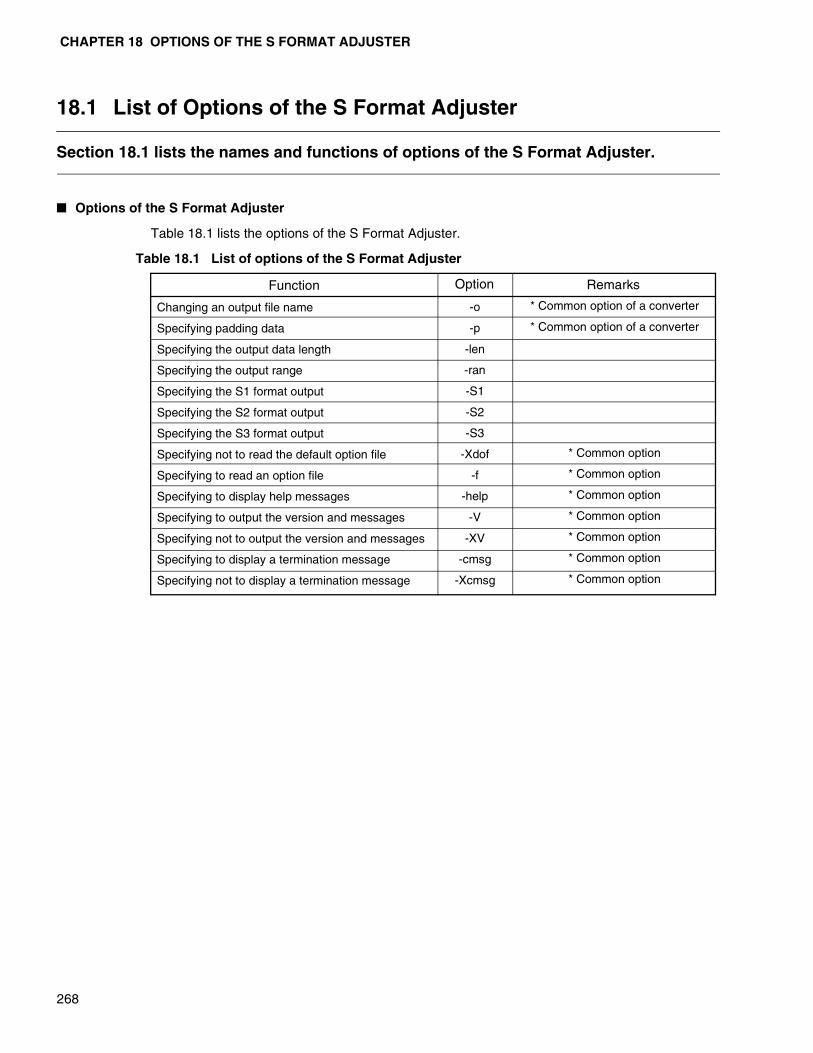
CHAPTER 18 OPTIONS OF THE S FORMAT ADJUSTER
268
18.1 List of Options of the S Format Adjuster
Section 18.1 lists the names and functions of options of the S Format Adjuster.
� Options of the S Format Adjuster
Table 18.1 lists the options of the S Format Adjuster.
Table 18.1 List of options of the S Format Adjuster
Function
Changing an output file name
Specifying padding data
Specifying the output data length
Specifying the output range
Specifying the S1 format output
Specifying the S2 format output
Specifying the S3 format output
Specifying not to read the default option file
Specifying to read an option file
Specifying to display help messages
Specifying to output the version and messages
Specifying not to output the version and messages
Specifying to display a termination message
Specifying not to display a termination message
Option
-o
-p
-len
-ran
-S1
-S2
-S3
-Xdof
-f
-help
-V
-XV
-cmsg
-Xcmsg
Remarks
* Common option of a converter
* Common option of a converter
* Common option
* Common option
* Common option
* Common option
* Common option
* Common option
* Common option
18.2 Details of Options of the S Format Adjuster
269
18.2 Details of Options of the S Format Adjuster
Section 18.2 describes the options of the S Format Adjuster.For information on the common options of Linkagekit, see Chapter 3, “CommonOptions.” For information on the common options of a converter, see Chapter 14,“Object Format Converter.”
� Specifying the output record data length (-len)
This option specifies the output record data length. For details, see Section 18.2.1, “Specifying the data length in an output record (-len)”.
� Specifying the output range (-ran)
This option specifies the range of formatting an S format file. For details, see Section 18.2.2, “Specifying the output range (-ran)”.
� Specifying an output record (-S1/-S2/-S3)
This option specifies an S record to be used when data is output in the S format. For details, see Section 18.2.3, “Specifying an output record (-S1/-S2/-S3).”

CHAPTER 18 OPTIONS OF THE S FORMAT ADJUSTER
270
18.2.1 Specifying the Data Length in an Output Record (-len)
Use this option to specify the number of data to be output into a record of an S formatfile.
� Specifying the data length in an output record (-len)
[Syntax]
[Parameter]
<Data length>
Select 16, 32, 64, or 128.
[Description]
Use this option to specify the number of bytes of data to be output into one record when an Sformat file is formatted.
Specify 16, 32, 64, or 128 as the data length.
If this option is omitted, 16 is assumed to be specified in the processing.
[Precautions]
This option specifies the number of bytes of data contained in one record, not the recordlength itself.
This option is valid for the S1, S2, and S3 records.
[Example]
m2ms sfmtfile.mhx -len 32
sfmtfile.mhx is formatted and 32-byte data is output per record.
m2ms sfmtfile.mhx (An example of omitting the -len specification)
sfmtfile.mhx is formatted and 16-byte data is output per record.
m2ms sfmtfile.mhx -len 96
An error occurs because the specified data length is out of the specifiable range.
m2ms sfmtfile.mhx -len (An example of omitting all the parameters)
An error occurs because the data length specification is omitted.
-len <Data length>

18.2 Details of Options of the S Format Adjuster
271
18.2.2 Specifying the Output Range (-ran)
Use this option to specify the range of formatting an S format file using addresses.
� Specifying the output range (-ran)
[Syntax]
[Parameters]
<Starting address>Starting address<Ending address>Ending address
[Description]
Use this option to specify the range of formatting an S format file using addresses.
You must specify this option in order to convert.
Specify the starting and ending addresses between 0x0 and 0xffffffff inclusive.
The ending address may be omitted. If omitted, data as much as 64Kbytes from the startingaddress is formatted.
You cannot specify values that will make the conversion size more than 2Gbytes.
[Example]
m2ms sfmtfile.mhx (Example of not using the -ran option)
An error occurs because the output range is not specified.
m2ms sfmtfile.mhx -ran 0xD000,0xFFFF
The data in sfmtfile.mhx at the addresses 0xD000 through 0xFFFF is formatted.
m2ms sfmtfile.mhx -ran 0xD000 (An example of omitting the ending address)
The data in sfmfile.mhx as much as 64Kbytes from the addresses 0xD000 (0x0D000 through0x1CFFF) is formatted.
m2ms sfmtfile.mhx -ran 0xFFFF,0xD000
An error occurs because the specified ending address is smaller than the starting address.
m2ms sfmtfile.mhx -ran (An example of omitting all the parameters)
An error occurs because the starting address is omitted.
-ran <Starting address> [ , <Ending address>]

CHAPTER 18 OPTIONS OF THE S FORMAT ADJUSTER
272
18.2.3 Specifying an Output Record (-S1/-S2/-S3)
Use this option to specify an S record to be used when data is output.
� Specifying an output record (-S1/-S2/-S3)
[Syntax]
[Parameter]
None
[Description]
Use this option to specify an S record to be used when data contents are output.
The S Format Adjuster outputs the data contents using one of the S1, S2, and S3 records.
It never outputs data using both the S1 and S2 records.
If more than one of the -S1, -S2, and -S3 options are specified, the one most recentlyspecified is valid. If none of the -S1, -S2, and -S3 options are specified, the S FormatAdjuster outputs the data contents into the S3 record.
[Precautions]
If the specification in this option and the output range are not consistent with each other, theS Format Adjuster reports an error and performs no processing.
Specifying this option changes the terminator record to be used for output (S9, S8, and S7records). (See Table 18.2.)
Table 18.2 List of output record specifications
[Example]
m2ms sfmtfile.mhx -ran 0xD000,0x10000 -S1
An error occurs because the output range is up to 0x10000, which cannot be represented inthe S1 record.
-S1
-S2
-S3
Specification
-S1
-S2
-S3
Terminator record
S9 record
S8 record
S7 record
Remarks
(Default)
Range of data that can be output
0x0000-0xFFFF
0x000000-0xFFFFFF
0x00000000-0xFFFFFFFF

18.2 Details of Options of the S Format Adjuster
273
m2ms sfmtfile.mhx -ran 0xE000,0xFFFF -S1
The data from 0xE000 through 0xFFFF is formatted and output in the S1 record.
m2ms sfmtfile.mhx -ran 0xE000,0xFFFF -S2
The data from 0xE000 through 0xFFFF is formatted and output in the S2 record.
m2ms sfmtfile.mhx -ran 0xE000,0xFFFF -S3
The data from 0xE000 through 0xFFFF is formatted and output in the S3 record.

274
MEMO
275
CHAPTER 19 LOAD MODULE CONVERTERS
Chapter 19 describes the commands of load module converters in detail.
19.1 Converting an Absolute Format Load Module into the Motorola S format
19.2 Converting an Absolute Format Load Module into the Intel HEX format
19.3 Converting an Absolute Format Load Module into the Intel extended HEX format
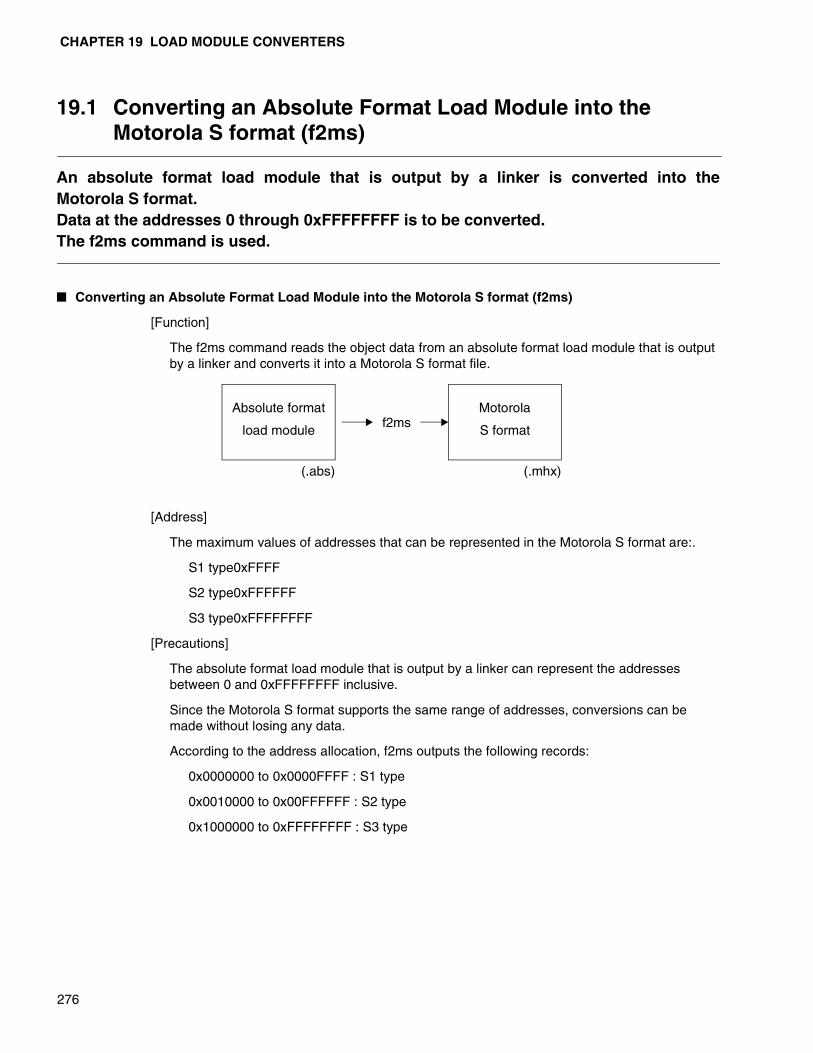
CHAPTER 19 LOAD MODULE CONVERTERS
276
19.1 Converting an Absolute Format Load Module into the Motorola S format (f2ms)
An absolute format load module that is output by a linker is converted into theMotorola S format.Data at the addresses 0 through 0xFFFFFFFF is to be converted.The f2ms command is used.
� Converting an Absolute Format Load Module into the Motorola S format (f2ms)
[Function]
The f2ms command reads the object data from an absolute format load module that is output by a linker and converts it into a Motorola S format file.
[Address]
The maximum values of addresses that can be represented in the Motorola S format are:.
S1 type0xFFFF
S2 type0xFFFFFF
S3 type0xFFFFFFFF
[Precautions]
The absolute format load module that is output by a linker can represent the addresses between 0 and 0xFFFFFFFF inclusive.
Since the Motorola S format supports the same range of addresses, conversions can be made without losing any data.
According to the address allocation, f2ms outputs the following records:
0x0000000 to 0x0000FFFF : S1 type
0x0010000 to 0x00FFFFFF : S2 type
0x1000000 to 0xFFFFFFFF : S3 type
Absolute format
load module
Motorola
S formatf2ms
(.abs) (.mhx)
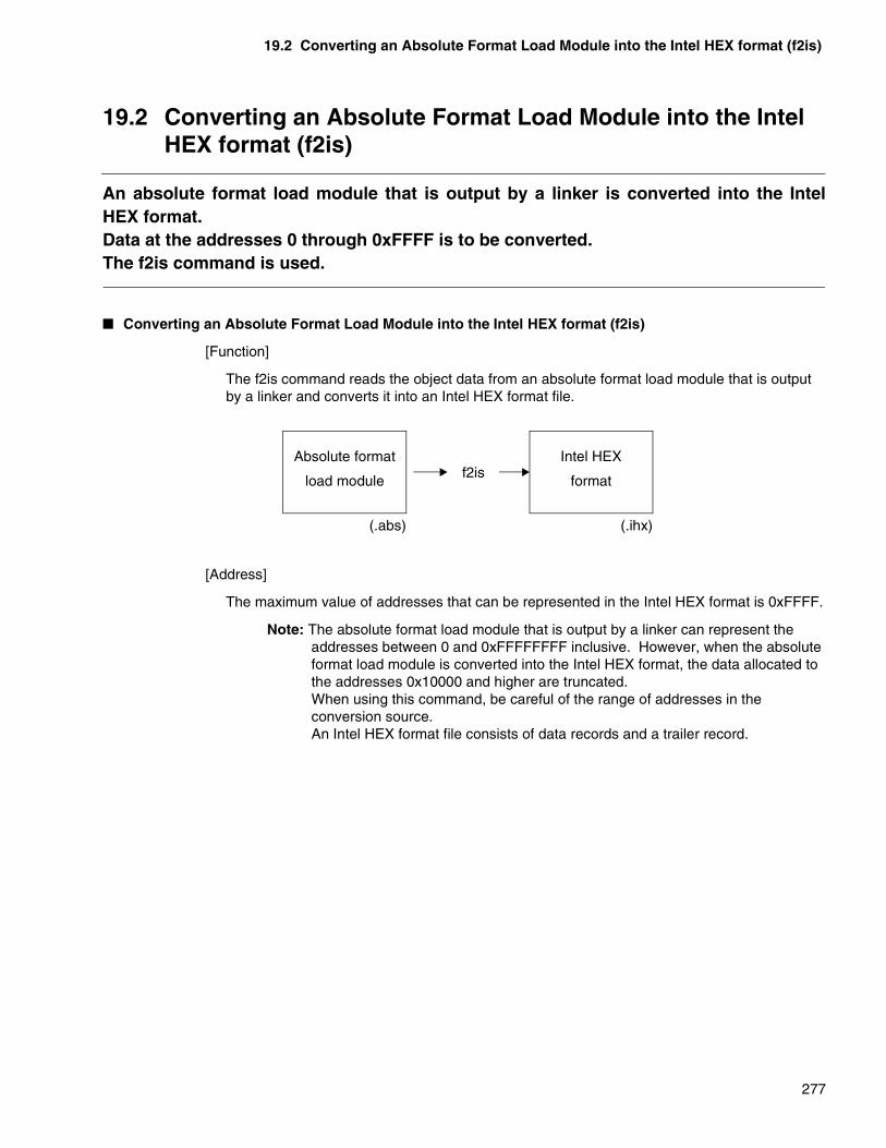
19.2 Converting an Absolute Format Load Module into the Intel HEX format (f2is)
277
19.2 Converting an Absolute Format Load Module into the Intel HEX format (f2is)
An absolute format load module that is output by a linker is converted into the IntelHEX format.Data at the addresses 0 through 0xFFFF is to be converted.The f2is command is used.
� Converting an Absolute Format Load Module into the Intel HEX format (f2is)
[Function]
The f2is command reads the object data from an absolute format load module that is output by a linker and converts it into an Intel HEX format file.
[Address]
The maximum value of addresses that can be represented in the Intel HEX format is 0xFFFF.
Note: The absolute format load module that is output by a linker can represent the addresses between 0 and 0xFFFFFFFF inclusive. However, when the absolute format load module is converted into the Intel HEX format, the data allocated to the addresses 0x10000 and higher are truncated.When using this command, be careful of the range of addresses in the conversion source.An Intel HEX format file consists of data records and a trailer record.
Absolute format
load module
Intel HEX
formatf2is
(.abs) (.ihx)

CHAPTER 19 LOAD MODULE CONVERTERS
278
19.3 Converting an Absolute Format Load Module into the Intel extended HEX format (f2es)
An absolute format load module that is output by a linker is converted into the Intelextended HEX format.The data at the addresses 0 through 0xFFFFF is to be converted.The f2es command is used.
� Converting an Absolute Format Load Module into the Intel extended HEX format (f2es)
[Function]
The f2es command reads the object data from an absolute format load module that is output by a linker and converts it into an Intel extended HEX format file.
[Address]
The maximum value of addresses that can be represented in the Intel extended HEX format is 0xFFFFF.
Note: The absolute format load module that is output by a linker can represent the addresses between 0 and 0xFFFFFFFF inclusive. However, when the absolute format load module is converted into the Intel extended HEX format, the data allocated to the addresses 0x100000 and higher are truncated.When using this command, be careful of the range of addresses in the conversion source.In the Intel extended HEX format, an extended address record is used to represent the addresses 0x10000 and higher.An extended address record in a file is valid until the next extended address record appears. If a data record appears without an extended address record, then the program calculates addresses assuming that the extended address is specified to be 0.A starting address record is created at the beginning of an Intel extended HEX format file.
Absolute format
load module
Intel extended
HEX formatf2es
(.abs) (.ehx)

279
CHAPTER 20 OTHER CONVERTERS
Chapter 20 describes the commands of load module converters in detail.
20.1 Converting a Motorola S Format File into the Intel HEX Format
20.2 Converting a Motorola S Format File into the Intel Extended HEX Format
20.3 Converting an Intel HEX Format File into the Motorola S Format
20.4 Converting an Intel Extended HEX Format File into the Motorola S Format
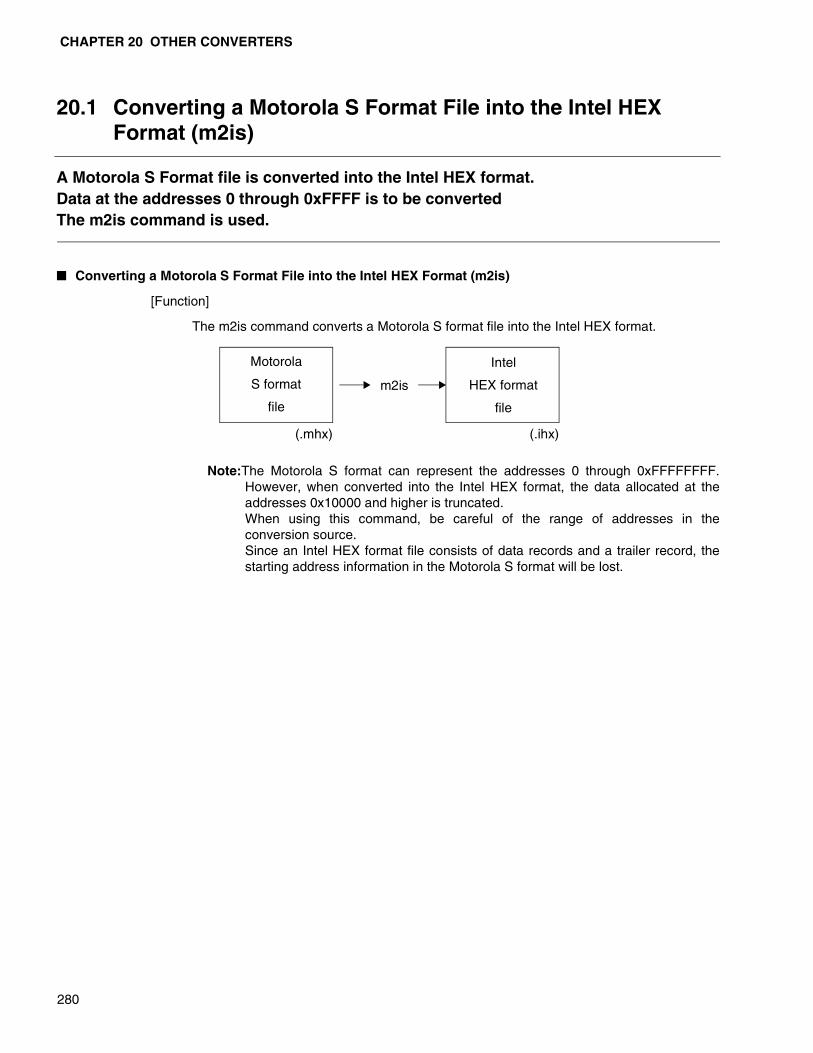
CHAPTER 20 OTHER CONVERTERS
280
20.1 Converting a Motorola S Format File into the Intel HEX Format (m2is)
A Motorola S Format file is converted into the Intel HEX format.Data at the addresses 0 through 0xFFFF is to be convertedThe m2is command is used.
� Converting a Motorola S Format File into the Intel HEX Format (m2is)
[Function]
The m2is command converts a Motorola S format file into the Intel HEX format.
Note:The Motorola S format can represent the addresses 0 through 0xFFFFFFFF.However, when converted into the Intel HEX format, the data allocated at theaddresses 0x10000 and higher is truncated. When using this command, be careful of the range of addresses in theconversion source. Since an Intel HEX format file consists of data records and a trailer record, thestarting address information in the Motorola S format will be lost.
Motorola
S format
file
Intel
HEX format
file
m2is
(.mhx) (.ihx)
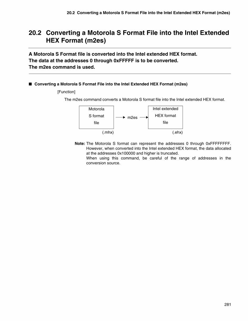
20.2 Converting a Motorola S Format File into the Intel Extended HEX Format (m2es)
281
20.2 Converting a Motorola S Format File into the Intel Extended HEX Format (m2es)
A Motorola S Format file is converted into the Intel extended HEX format.The data at the addresses 0 through 0xFFFFF is to be converted.The m2es command is used.
� Converting a Motorola S Format File into the Intel Extended HEX Format (m2es)
[Function]
The m2es command converts a Motorola S format file into the Intel extended HEX format.
Note: The Motorola S format can represent the addresses 0 through 0xFFFFFFFF.However, when converted into the Intel extended HEX format, the data allocatedat the addresses 0x100000 and higher is truncated. When using this command, be careful of the range of addresses in theconversion source.
Motorola
S format
file
Intel extended
HEX format
filem2es
(.mhx) (.ehx)

CHAPTER 20 OTHER CONVERTERS
282
20.3 Converting an Intel HEX Format File into the Motorola S Format (i2ms)
An Intel HEX format is converted into the Motorola S format.The data at the addresses 0 through 0xFFFF is to be converted.The i2ms command is used.
� Converting an Intel HEX Format File into the Motorola S Format (i2ms)
[Function]
The i2ms command converts an Intel HEX format file into the Motorola S format.
Note: Although the Motorola S format can represent the addresses 0 through0xFFFFFFFF, the Intel HEX format cannot represent the addresses 0x10000and higher. A Motorola S format file after conversion is created without the S2,S3, S7, and S8 types. Since the Intel HEX format does not have starting address information, thestarting address after conversion is to be 0.
Intel
HEX format
file
Motorola
S format
file
i2ms
(.ihx) (.mhx)

20.4 Converting an Intel Extended HEX Format File into the Motorola S Format (e2ms)
283
20.4 Converting an Intel Extended HEX Format File into the Motorola S Format (e2ms)
An Intel extended HEX format is converted into the Motorola S format.The data at the addresses 0 through 0xFFFFF is to be converted.The e2ms command is used.
� Converting an Intel Extended HEX Format File into the Motorola S Format (e2ms)
[Function]
The e2ms command converts an Intel extended HEX format file into the Motorola Sformat.
Note: Although the Motorola S format can represent the addresses 0 through0xFFFFFFFF, the Intel extended HEX format cannot represent the addresses0x100000 and higher. A Motorola S format file after conversion is createdwithout the S7 and S3 types.The starting address information in the Intel extended HEX format is set in theS9 or S8 type.
Intel extended
HEX format
file
Motorola
S format
file
e2ms
(.ehx) (.mhx)

284
MEMO
285
CHAPTER21 RESTRICTIONS AND QUESTIONS AND ANSWERS ON AN OBJECT FORMAT CONVERTER
Chapter 21 describes restrictions and questions and answers on using an objectformat converter.
21.1 Restrictions on an Object Format Converter
21.2 Questions and Answers on Using an Object Format Converter
CHAPTER21 RESTRICTIONS AND QUESTIONS AND ANSWERS ON AN OBJECT FORMAT CONVERTER
286
21.1 Restrictions on an Object Format Converter
There are some restrictions on the S Format Binary Converter. There are norestrictions on using other converters. Processing can be performed until a converteruses up all the available memory.
� Restrictions on a converter
For a converter, there are no restrictions on the processing such as the numbers of sections and symbols.
If the numbers of sections and symbols need to be registered in the internal processing of a converter, the memory is dynamically acquired.
When the processing limit is reached, a message for a shortage of memory is reported and the converter is terminated.
� Restrictions on S Format Binary Converter
Up to 64 S format files can be specified in total.
If multiple S format files are specified, they are processed in the order in which they are specified.
Any data contained in an S format file at the same address is overwritten with data created later.
Up to 2Gbytes minus 1 byte can be converted at one time.
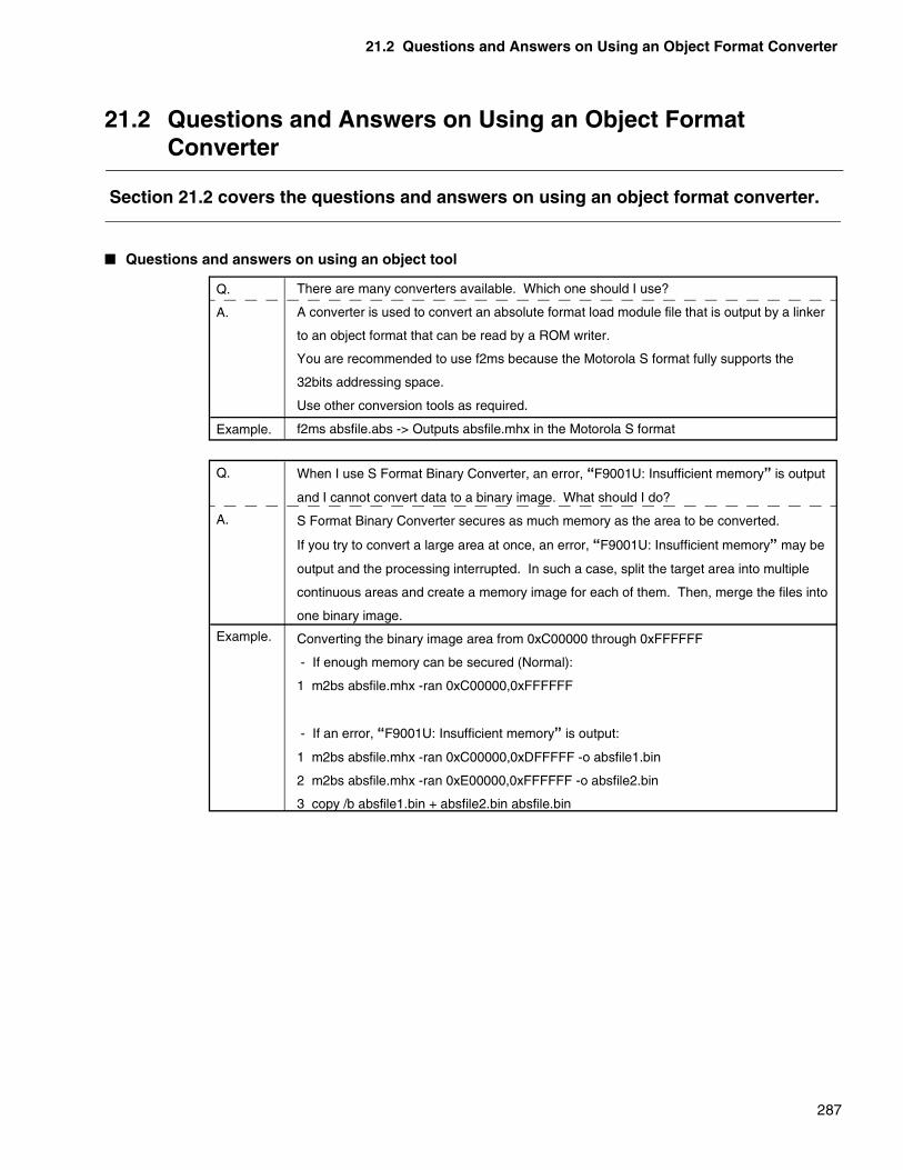
21.2 Questions and Answers on Using an Object Format Converter
287
21.2 Questions and Answers on Using an Object Format Converter
Section 21.2 covers the questions and answers on using an object format converter.
� Questions and answers on using an object tool
Q.
A.
Example.
There are many converters available. Which one should I use?
A converter is used to convert an absolute format load module file that is output by a linker
to an object format that can be read by a ROM writer.
You are recommended to use f2ms because the Motorola S format fully supports the
32bits addressing space.
Use other conversion tools as required.
f2ms absfile.abs -> Outputs absfile.mhx in the Motorola S format
Q.
A.
Example.
When I use S Format Binary Converter, an error, “F9001U: Insufficient memory” is output
and I cannot convert data to a binary image. What should I do?
S Format Binary Converter secures as much memory as the area to be converted.
If you try to convert a large area at once, an error, “F9001U: Insufficient memory” may be
output and the processing interrupted. In such a case, split the target area into multiple
continuous areas and create a memory image for each of them. Then, merge the files into
one binary image.
Converting the binary image area from 0xC00000 through 0xFFFFFF
- If enough memory can be secured (Normal):
1 m2bs absfile.mhx -ran 0xC00000,0xFFFFFF
- If an error, “F9001U: Insufficient memory” is output:
1 m2bs absfile.mhx -ran 0xC00000,0xDFFFFF -o absfile1.bin
2 m2bs absfile.mhx -ran 0xE00000,0xFFFFFF -o absfile2.bin
3 copy /b absfile1.bin + absfile2.bin absfile.bin

288
MEMO

289
APPENDIXES
These appendixes describe the error messages of the linkage kit, Intel HEX, Intelextended HEX format, and Motorola S record format.
APPENDIX A ERROR MESSAGES OF THE LINKAGE KIT
APPENDIX B INTEL HEX AND INTEL EXTENDED HEX FORMAT
APPENDIX C MOTOROLA S RECORD FORMAT
APPENDIX D LIST OF LINKER OPTIONS
APPENDIX E LIST OF LIBRARIAN OPTIONS
APPENDIX F LIST OF COMMANDS AND OPTIONS OF THE OBJECT FORMAT CONVERTER
APPENDIX G SPECIFICATION DIFFERENCES DEPENDING ON THE OS

290
MEMO

291
APPENDIX A ERROR MESSAGES OF THE LINKAGE KIT
This section explains the classification of error messages output by each tool of thelinkage kit and the display format.
� Linkage Kit Error Message Classes
Error messages can be classified into the following four levels based on their importance.
❍ Information
Information notifies the user of contents of processing to confirm the processing. Sincethis in no errors, and the user can obtain correct processing results.
❍ Warning
Warnings are slighter than errors, and output results can be used almost without causingany trouble. It is possible that other processing than the user system is executed. Checkthe contents of messages before determining whether output results can be used.
❍ Error
Processing continues to be executed, but troubles have occurred which make itimpossible to obtain correct results. The causes of errors must be removed before rerun.
❍ Fatal error
Errors which make it impossible to continue processing. This type of errors results fromwrong specifications of the user or problems of the execution environment.
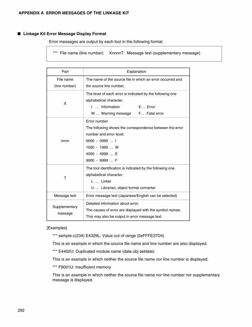
APPENDIX A ERROR MESSAGES OF THE LINKAGE KIT
292
� Linkage Kit Error Message Display Format
Error messages are output by each tool in the following format.
[Examples]
*** sample.c(234) E4329L: Value out of range (0xFFFE37D4)
This is an example in which the source file name and line number are also displayed.
*** E4402U: Duplicated module name (date.obj setdate)
This is an example in which neither the source file name nor line number is displayed.
*** F9001U: Insufficient memory
This is an example in which neither the source file name nor line number nor supplementary message is displayed.
Part Explanation
File name
(line number)
The name of the source file in which an error occurred and
the source line number.
X
The level of each error is indicated by the following one
alphabetical character.
I … Information E… Error
W … Warning message F… Fatal error
nnnn
Error number
The following shows the correspondence between the error
number and error level.
0000 - 0999 ... I
1000 - 1999 ... W
4000 - 4999 ... E
9000 - 9999 ... F
T
The tool identification is indicated by the following one
alphabetical character.
L … Linker
U … Librarian, object format converter
Message text Error message text (Japanese/English can be selected)
Supplementary
message
Detailed information about error.
The causes of error are displayed with the symbol names.
This may also be output in error message text.
*** File name (line number) XnnnnT: Message text (supplementary message)

APPENDIX A ERROR MESSAGES OF THE LINKAGE KIT
293
� Error Messages of the Linker
There are one or more libraries that were not used in linking process.
This is a message which is notified when 2 is specified in the -w option.
Debug information is not contained in the input file.
This is a message which is notified when 2 is specified in the -w option.
The error is slighter than W1351.
The message only report that debug information does not exist.
Output file was created after removing debug information.
This is a message which is notified when 2 is specified in the -w option.
The file indicated here was warned in a warning message when linking.
This is a message which is notified when 2 is specified in the -w option.
Because the -pk option was specified, allocation was carried out ignoring boundary alignment when linking.
This is a message which is notified when 2 is specified in the -w option.
Optimal section allocation was carried out in the area indicated here.
This is a message which is notified when 2 is specified in the -w option.
I0301L Unused library (file name)
I0302L Debug information not exist (file name)
I0303L Removed debug information
I0304L File include WARNING level error (file name)
I0305L Ignore address alignment
I0306L Section allocated automatically in “section name” area
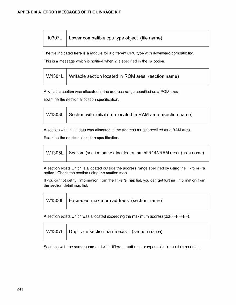
APPENDIX A ERROR MESSAGES OF THE LINKAGE KIT
294
The file indicated here is a module for a different CPU type with downward compatibility.
This is a message which is notified when 2 is specified in the -w option.
A writable section was allocated in the address range specified as a ROM area.
Examine the section allocation specification.
A section with initial data was allocated in the address range specified as a RAM area.
Examine the section allocation specification.
A section exists which is allocated outside the address range specified by using the -ro or -ra option. Check the section using the section map.
If you cannot get full information from the linker's map list, you can get further information from the section detail map list.
A section exists which was allocated exceeding the maximum address(0xFFFFFFFF).
Sections with the same name and with different attributes or types exist in multiple modules.
I0307L Lower compatible cpu type object (file name)
W1301L Writable section located in ROM area (section name)
W1303L Section with initial data located in RAM area (section name)
W1305L Section (section name) located on out of ROM/RAM area (area name)
W1306L Exceeded maximum address (section name)
W1307L Duplicate section name exist (section name)

APPENDIX A ERROR MESSAGES OF THE LINKAGE KIT
295
Section allocation is overlapped. Since program operations may be affected depending on the situation, care must be taken.
It is recommended to avoid overlapping by using the options.
Since the absolute address has been determined for the section indicated here, the specified section relocation is illegal.
Library retrieval processing is used only when creating absolute format load modules.
The library retrieval specification when the -r option is specified is illegal.
The following is displayed in the mode identification of the supplementary message.
• If the relative format load module output is specified(-r):REL
This message is notified when an illegal specification in the specified link mode is set.
For example, since no section allocation is carried out when relative format load module output is specified, it is illegal to specify the -sc option.
Entry points are set in multiple input modules.
The entry point set first is valid.
The entry point already set has been changed by specifying the -e option.
W1308L Overlap located section (section 1, section 2)
W1314L Specified address to absolute section (section name)
W1320L Not search library at mode-identification mode
W1321L Ignore (option) Option at mode-identification mode
W1325L Entry point already set
W1326L Entry point was changed
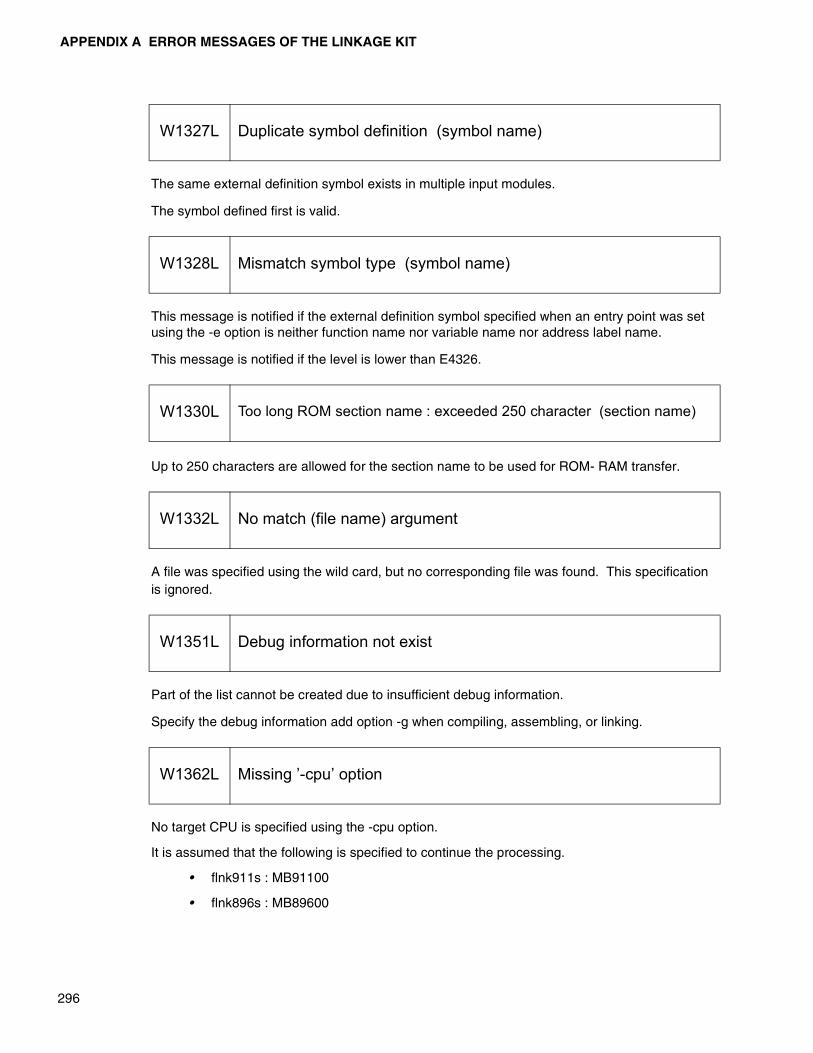
APPENDIX A ERROR MESSAGES OF THE LINKAGE KIT
296
The same external definition symbol exists in multiple input modules.
The symbol defined first is valid.
This message is notified if the external definition symbol specified when an entry point was set using the -e option is neither function name nor variable name nor address label name.
This message is notified if the level is lower than E4326.
Up to 250 characters are allowed for the section name to be used for ROM- RAM transfer.
A file was specified using the wild card, but no corresponding file was found. This specification is ignored.
Part of the list cannot be created due to insufficient debug information.
Specify the debug information add option -g when compiling, assembling, or linking.
No target CPU is specified using the -cpu option.
It is assumed that the following is specified to continue the processing.
• flnk911s : MB91100
• flnk896s : MB89600
W1327L Duplicate symbol definition (symbol name)
W1328L Mismatch symbol type (symbol name)
W1330L Too long ROM section name : exceeded 250 character (section name)
W1332L No match (file name) argument
W1351L Debug information not exist
W1362L Missing ’-cpu’ option
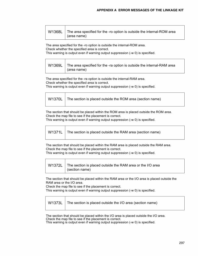
APPENDIX A ERROR MESSAGES OF THE LINKAGE KIT
297
The area specified for the -ro option is outside the internal-ROM area.Check whether the specified area is correct.This warning is output even if warning output suppression (-w 0) is specified.
The area specified for the -ra option is outside the internal-RAM area.Check whether the specified area is correct.This warning is output even if warning output suppression (-w 0) is specified.
The section that should be placed within the ROM area is placed outside the ROM area.Check the map file to see if the placement is correct.This warning is output even if warning output suppression (-w 0) is specified.
The section that should be placed within the RAM area is placed outside the RAM area.Check the map file to see if the placement is correct.This warning is output even if warning output suppression (-w 0) is specified.
The section that should be placed within the RAM area or the I/O area is placed outside the RAM area or the I/O area.Check the map file to see if the placement is correct.This warning is output even if warning output suppression (-w 0) is specified.
The section that should be placed within the I/O area is placed outside the I/O area.Check the map file to see if the placement is correct.This warning is output even if warning output suppression (-w 0) is specified.
W1368L The area specified for the -ro option is outside the internal-ROM area (area name)
W1369L The area specified for the -ra option is outside the internal-RAM area (area name)
W1370L The section is placed outside the ROM area (section name)
W1371L The section is placed outside the RAM area (section name)
W1372L The section is placed outside the RAM area or the I/O area(section name)
W1373L The section is placed outside the I/O area (section name)
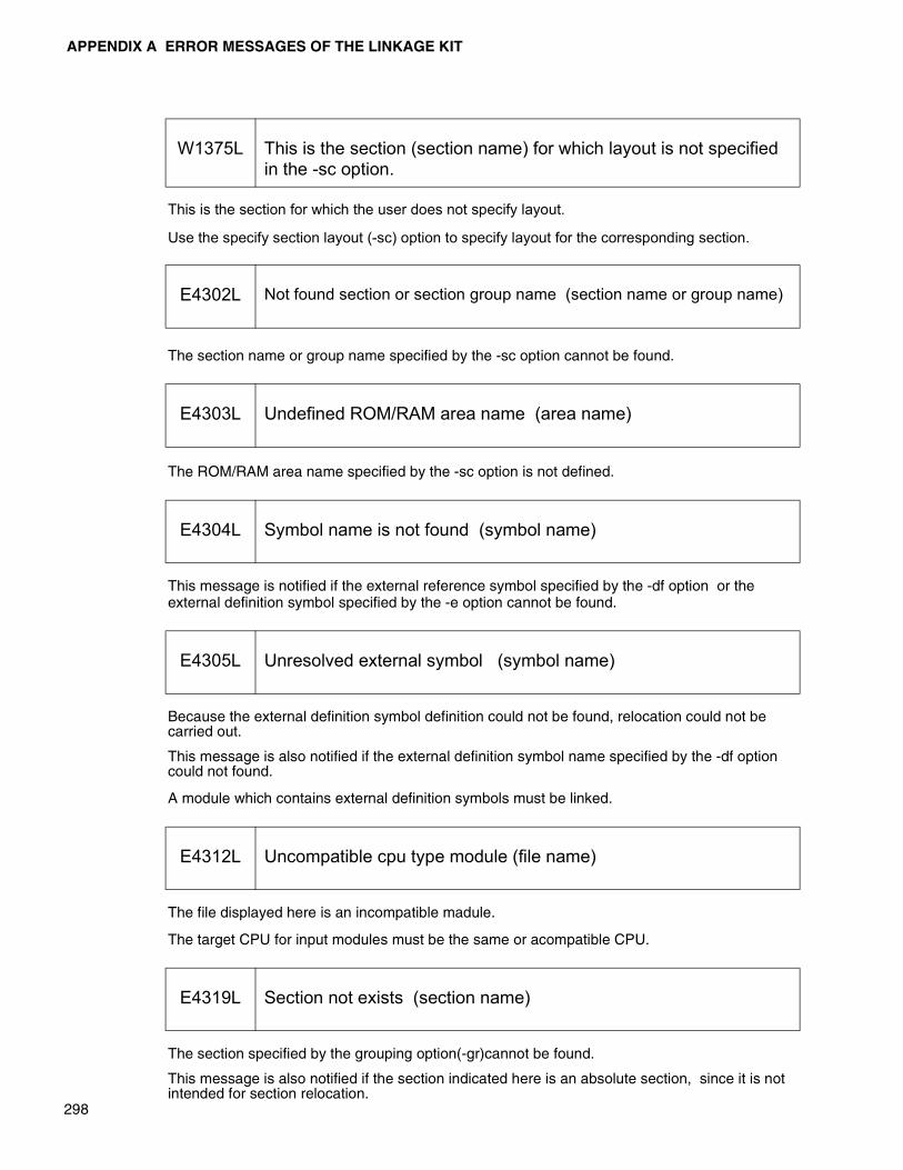
APPENDIX A ERROR MESSAGES OF THE LINKAGE KIT
298
This is the section for which the user does not specify layout.
Use the specify section layout (-sc) option to specify layout for the corresponding section.
The section name or group name specified by the -sc option cannot be found.
The ROM/RAM area name specified by the -sc option is not defined.
This message is notified if the external reference symbol specified by the -df option or the external definition symbol specified by the -e option cannot be found.
Because the external definition symbol definition could not be found, relocation could not be carried out.
This message is also notified if the external definition symbol name specified by the -df option could not found.
A module which contains external definition symbols must be linked.
The file displayed here is an incompatible madule.
The target CPU for input modules must be the same or acompatible CPU.
The section specified by the grouping option(-gr)cannot be found.
This message is also notified if the section indicated here is an absolute section, since it is not intended for section relocation.
W1375L This is the section (section name) for which layout is not specified in the -sc option.
E4302L Not found section or section group name (section name or group name)
E4303L Undefined ROM/RAM area name (area name)
E4304L Symbol name is not found (symbol name)
E4305L Unresolved external symbol (symbol name)
E4312L Uncompatible cpu type module (file name)
E4319L Section not exists (section name)
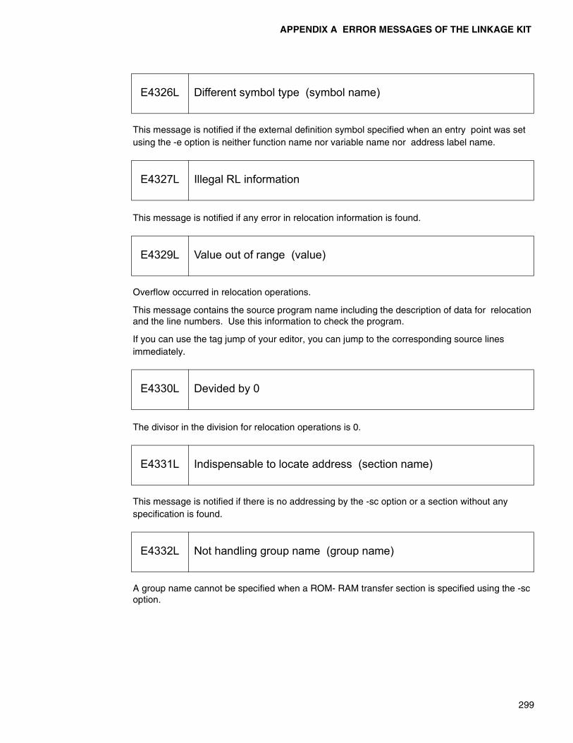
APPENDIX A ERROR MESSAGES OF THE LINKAGE KIT
299
This message is notified if the external definition symbol specified when an entry point was set using the -e option is neither function name nor variable name nor address label name.
This message is notified if any error in relocation information is found.
Overflow occurred in relocation operations.
This message contains the source program name including the description of data for relocation and the line numbers. Use this information to check the program.
If you can use the tag jump of your editor, you can jump to the corresponding source lines immediately.
The divisor in the division for relocation operations is 0.
This message is notified if there is no addressing by the -sc option or a section without any specification is found.
A group name cannot be specified when a ROM- RAM transfer section is specified using the -sc option.
E4326L Different symbol type (symbol name)
E4327L Illegal RL information
E4329L Value out of range (value)
E4330L Devided by 0
E4331L Indispensable to locate address (section name)
E4332L Not handling group name (group name)
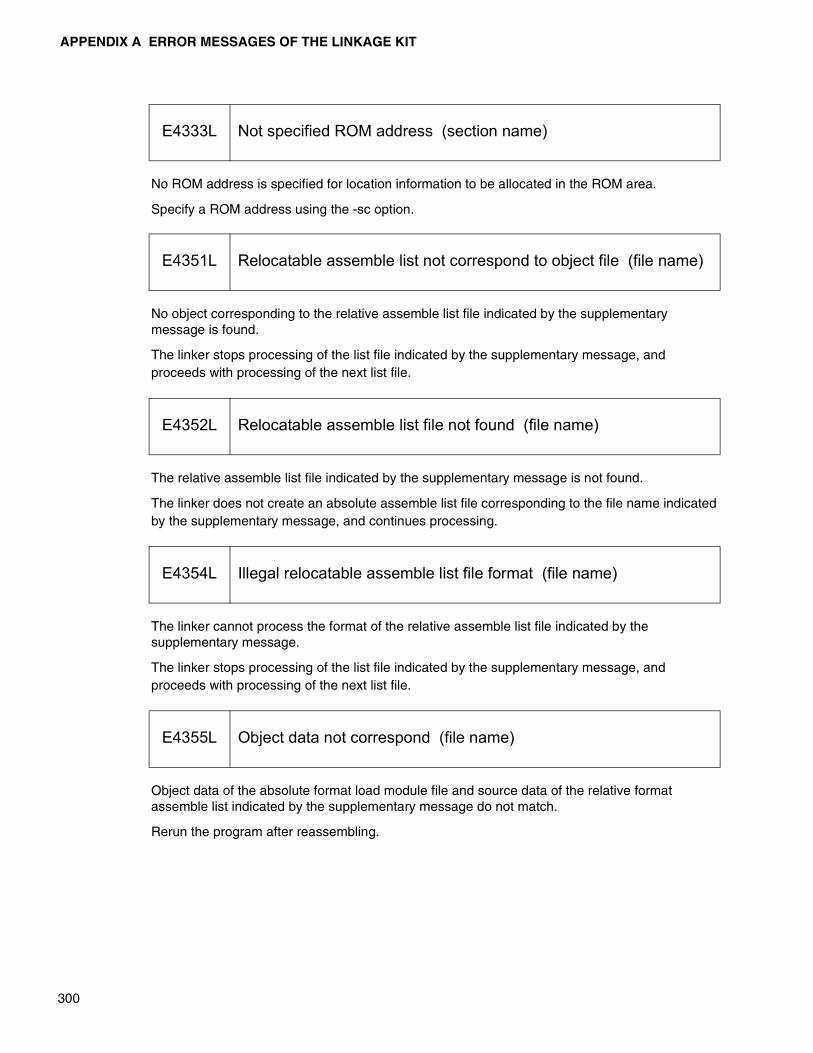
APPENDIX A ERROR MESSAGES OF THE LINKAGE KIT
300
No ROM address is specified for location information to be allocated in the ROM area.
Specify a ROM address using the -sc option.
No object corresponding to the relative assemble list file indicated by the supplementary message is found.
The linker stops processing of the list file indicated by the supplementary message, and proceeds with processing of the next list file.
The relative assemble list file indicated by the supplementary message is not found.
The linker does not create an absolute assemble list file corresponding to the file name indicated by the supplementary message, and continues processing.
The linker cannot process the format of the relative assemble list file indicated by the supplementary message.
The linker stops processing of the list file indicated by the supplementary message, and proceeds with processing of the next list file.
Object data of the absolute format load module file and source data of the relative format assemble list indicated by the supplementary message do not match.
Rerun the program after reassembling.
E4333L Not specified ROM address (section name)
E4351L Relocatable assemble list not correspond to object file (file name)
E4352L Relocatable assemble list file not found (file name)
E4354L Illegal relocatable assemble list file format (file name)
E4355L Object data not correspond (file name)

APPENDIX A ERROR MESSAGES OF THE LINKAGE KIT
301
The number of dimensions of an array output to the ARRAY list or that of nesting levels of a structure exceeds 8.
Processing continues, but those parts which exceed this limit are not output.
A dummy section is specified in a file indicated by the supplementary message.
Do not write any dummy section when creating an absolute assemble list.
One or more sections which exceed the maximum size of a section exist. Some sections are have the maximum size depending on their section identification. This message is output if such limits are exceeded.
Examine such sections.
This message is notified if the maximum address of the bank is exceeded when the section is allocated from the specified location.
Examine the section configuration in the bank.
No place in the specified allocation area can be found where the applicable section can be allocated.
Examine the section configuration in the area.
E4357L Too many array dimension or structure nested : exceeded 8
E4362L DUMMY section specified (file name)
E4363L Exceeded maximum section size (section name)
E4364L Exceeded maximum bank address (section name)
E4365L Not found locatable address in area name (section name)

APPENDIX A ERROR MESSAGES OF THE LINKAGE KIT
302
No place in all address space can be found where the section can be allocated.
Examine the program structure.
The same module name already exists as that intended for linking.
Duplicated module names are not allowed. Change the module names.
A symbol defined in another bank was referenced in an intra-bank branch instruction.
Use a branch instruction to outside banks if the branch to the corresponding location (symbol) is
required.
Can't find the target CPU information file specified by the -cpu option.This is detected when the file below is not found.
• flnk896s : %FETOOL%\LIB\896\896.CSV
• flnk907s : %FETOOL%\LIB\907\907.CSV
• flnk911s : %FETOOL%\LIB\911\911.CSV
Can't find the target CPU information, in the CPU information file, specified by the -cpu option.This is detected when the target CPU information specified in the file below is not found.
• flnk896s : %FETOOL%\LIB\896\896.CSV
• flnk907s : %FETOOL%\LIB\907\907.CSV
• flnk911s : %FETOOL%\LIB\911\911.CSV
E4366L Not found locatable address (section name)
E4367L Duplicated module name (file name module name)
E4368L Referenced other bank symbol (symbol name)
E4370L CPU information file not found (file name)
E4371L CPU information not found (file name)

APPENDIX A ERROR MESSAGES OF THE LINKAGE KIT
303
Enough memory is not available to execute the program. If the linker is activated from a batch file, start the program directly from the command line.
The specified input file cannot be found.
If the name of the file indicated here is a default library file, the library file is not stored in the directory indicated by the environmental variable LIB*** or derived from the environmental variable FETOOL(...\fetool\lib).
If the file is a library file specified by the -l or -el option, check whether the file name is specified. correctly or the retrieval path specified in the -L option is correct.
If the file indicated here is an output file, it is possible that the number of files that can be managed by one directory is exceeded. Remove or move unnecessary files.
It is probable that the file is read-protected or hardware fault has occurred.
The disk does not have enough free space, so the file indicated here can be written. Prepare sufficient free space in the disk before rerunning the linker.
This message is also notified if a write-protected file with the same name exists.
F9001L Insufficient memory
F9011L Input file not found (file name)
F9012L Library file not found (file name)
F9015L File open error (file name)
F9016L File read error (file name)
F9017L File write error (file name)
APPENDIX A ERROR MESSAGES OF THE LINKAGE KIT
304
Too many input file names and options (including those in the option file) are specified on the command line.
Divide the files and options, and then activate the linker more than once
The option cannot be used by the linker. See the -help option or this manual.
An error is found in parameters to be specified for this option.
It is probable that the parameters fall short or a syntactical error such as a delimiter error has occurred.
An error is found in parameters to be specified for this option.
This message is notified if an error due to the use of illegal characters such as that in the method of specifying numeric values is assumed.
A value is specified which is outside the range of allowed values by the -pl, -pw, or -w option.
Nesting of option files is not allowed. Delete the -f option described in the option file.
Specify an input file.
F9021L Too many options
F9022L Illegal option name (option)
F9023L Illegal option parameter (option)
F9024L Illegal character (option)
F9026L Specified value out of range (value)
F9027L Option file nested
F9030L Missing input file name
APPENDIX A ERROR MESSAGES OF THE LINKAGE KIT
305
Since the output file name indicated here is the same as the input file name, processing cannot continue.
This message is notified in one of the following cases.
• The library file format is not correct.
• The object module format in a library file is not correct.
• The input file is an absolute format load module.
• Contents of an input module are not correct.
• The format of a relative format assemble list file is not correct.
• CPU Information file format is not correct.
This message is notified in one of the following three cases.
• Input module files of the same name are specified.
• Library files of the same name are specified in the -l, or -el option.
• The same library path name is specified in the -L option more than once.
The same section name was specified in the -sc or -gr option more than once.
The same external reference symbol was specified in the -el option more than once.
F9032L Output file name same as input one (file name)
F9033L Illegal file format (file name)
F9040L Duplicated file or path name (file name)
F9042L Duplicated section name (section name)
F9043L Duplicated symbol name (symbol name)
APPENDIX A ERROR MESSAGES OF THE LINKAGE KIT
306
The same group name was used more than once when setting groups using the -gr option.
A file was specified using the wild card, but no corresponding file was found.
No target CPU is specified using the -cpu option.
In flnk907s, the target CPU must be specified using the -cpu option.
The -ro option or -ra option required for automatic allocation is not specified.
The CPU information file is not suited old.Please obtain the CPU information file of the latest.
The message files used by the linker could not be opened.
Store the error message files(lkt***_a.msg,lkt***_e.msg)in a predetermined directory.
If this error occurs, report it to Fujitsu immediately.
F9044L Duplicated section group name (group name)
F9047L No match file name argument
F9052L Missing ’-cpu’ option
F9053L Missing ’-ro’ or ’-ra’ option
F9056L Mismatch CPU information file version
F9998L File open failed (file name)
F9999L Internal error (identification information)
APPENDIX A ERROR MESSAGES OF THE LINKAGE KIT
307
� Error Messages for the Librarian
This is a message reported if the -c option is specified. This message indicates that, after checking external symbols in the library file, external reference symbols that cannot be resolved in the library file are contained. When a library file for which this message is output is used in the linker, care must be taken to know to which module the external definition symbols to be used belong.
This is a message reported if the -c option is specified. This library file contains a module which contains debug information. Debug information in the library file can be removed using the -O option.
The file indicated here is an object file or a library file which contains a module of a different CPU type downwardly compatible with the library file.
Though the number of lines of the list is specified(-pl options), the output of the target map list is not specified. This specification is ignored.
Though the number of lines of the list is specified(-pw options), the output of the target map list is not specified. This specification is ignored.
The specification of creation of a library with debug information (-g option) has any meaning only if addition (-a option) or replacement (-r option) of a module is specified. This specification is ignored.
I0401U Reference to undefined symbol
I0402U Debug information exists
I0407U Lower compatible cpu type object (file name)
W1401U Ignore ’-pl’ option
W1402U Ignore ’-pw’ option
W1403U Ignore ’-g’ option

APPENDIX A ERROR MESSAGES OF THE LINKAGE KIT
308
There was no library file change nor module extract operation.
The module specified by the -d option is not included in the library file.
Check the registered module names using the -m option.
The module specified by the -x option is not included in the library file.
Check the registered module names using the -m option.
No target CPU is specified using the -cpu option.
It is assumed that the following is specified to continue the processing.
• flib911s: MB91100
• flib896s: MB89600
An attempt was made to register a module with the same name as that which has already been registered.
Duplicated names are not allowed in one library and so the module indicated here is not registered. Use the -r option for replacement.
W1404U Nothing to operate
W1405U Module not exists to delete (module name)
W1406U Module not exists to extract (module name)
W1462U Missing ’-cpu’ option
E4402U Duplicated module name (file name module name)

APPENDIX A ERROR MESSAGES OF THE LINKAGE KIT
309
The registered modules contain external definition symbols and the symbol indicated here has already been registered in the library.
Duplicated external definition symbols are not allowed in one library, the module which contains the symbol indicated here is not registered.
Only the object module format output by the assembler can be registered in the library file. The absolute format and relative format load modules output by the linker cannot be registered.
This is not an object file output by the family assembler that can be handled by this librarian. Or a library file created for another family librarian is specified.
A module of a different compile model (such as the memory model) cannot be registered in the same library.
A module of a different target CPU cannot be registered in the same library.
Create another library so that one library contains at most 65535 modules.
E4403U Duplicated external definition symbol name (file name symbol name)
E4404U Invalid module : type (file name)
E4405U Invalid module : conflict tool name (file name)
E4406U Invalid module : conflict compile model (file name)
E4407U Invalid module : conflict CPU type (file name)
E4408U Too many entry modules : exceed 65535
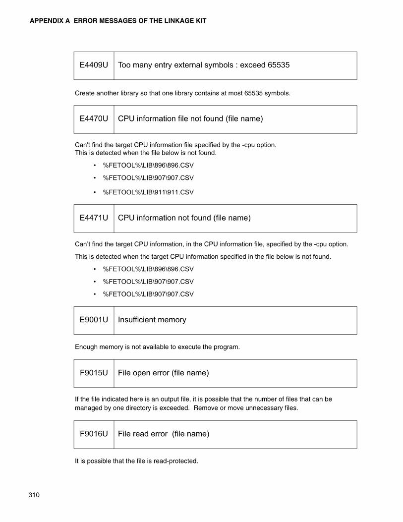
APPENDIX A ERROR MESSAGES OF THE LINKAGE KIT
310
Create another library so that one library contains at most 65535 symbols.
Can't find the target CPU information file specified by the -cpu option.This is detected when the file below is not found.
• %FETOOL%\LIB\896\896.CSV
• %FETOOL%\LIB\907\907.CSV
• %FETOOL%\LIB\911\911.CSV
Can’t find the target CPU information, in the CPU information file, specified by the -cpu option.
This is detected when the target CPU information specified in the file below is not found.
• %FETOOL%\LIB\896\896.CSV
• %FETOOL%\LIB\907\907.CSV
• %FETOOL%\LIB\907\907.CSV
Enough memory is not available to execute the program.
If the file indicated here is an output file, it is possible that the number of files that can be managed by one directory is exceeded. Remove or move unnecessary files.
It is possible that the file is read-protected.
E4409U Too many entry external symbols : exceed 65535
E4470U CPU information file not found (file name)
E4471U CPU information not found (file name)
E9001U Insufficient memory
F9015U File open error (file name)
F9016U File read error (file name)
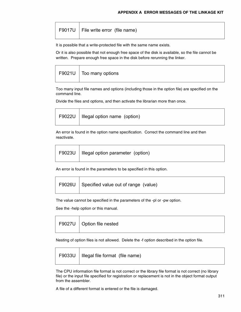
APPENDIX A ERROR MESSAGES OF THE LINKAGE KIT
311
It is possible that a write-protected file with the same name exists.
Or it is also possible that not enough free space of the disk is available, so the file cannot be written. Prepare enough free space in the disk before rerunning the linker.
Too many input file names and options (including those in the option file) are specified on the command line.
Divide the files and options, and then activate the librarian more than once.
An error is found in the option name specification. Correct the command line and then reactivate.
An error is found in the parameters to be specified in this option.
The value cannot be specified in the parameters of the -pl or -pw option.
See the -help option or this manual.
Nesting of option files is not allowed. Delete the -f option described in the option file.
The CPU information file format is not correct or the library file format is not correct (no library file) or the input file specified for registration or replacement is not in the object format output from the assembler.
A file of a different format is entered or the file is damaged.
F9017U File write error (file name)
F9021U Too many options
F9022U Illegal option name (option)
F9023U Illegal option parameter (option)
F9026U Specified value out of range (value)
F9027U Option file nested
F9033U Illegal file format (file name)
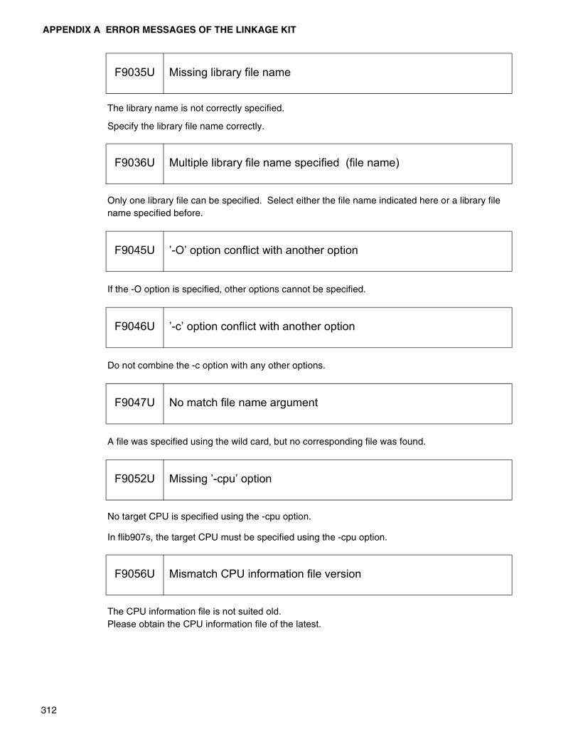
APPENDIX A ERROR MESSAGES OF THE LINKAGE KIT
312
The library name is not correctly specified.
Specify the library file name correctly.
Only one library file can be specified. Select either the file name indicated here or a library file name specified before.
If the -O option is specified, other options cannot be specified.
Do not combine the -c option with any other options.
A file was specified using the wild card, but no corresponding file was found.
No target CPU is specified using the -cpu option.
In flib907s, the target CPU must be specified using the -cpu option.
The CPU information file is not suited old.Please obtain the CPU information file of the latest.
F9035U Missing library file name
F9036U Multiple library file name specified (file name)
F9045U ’-O’ option conflict with another option
F9046U ’-c’ option conflict with another option
F9047U No match file name argument
F9052U Missing ’-cpu’ option
F9056U Mismatch CPU information file version

APPENDIX A ERROR MESSAGES OF THE LINKAGE KIT
313
The message files used by the library file could not be opened.
Store the error message files(lkt***_a.msg,lkt***_e.msg)in a predetermined directory.
If this error occurs, report it to Fujitsu immediately.
F9998U File open failed (file name)
F9999U Internal error (identification information)
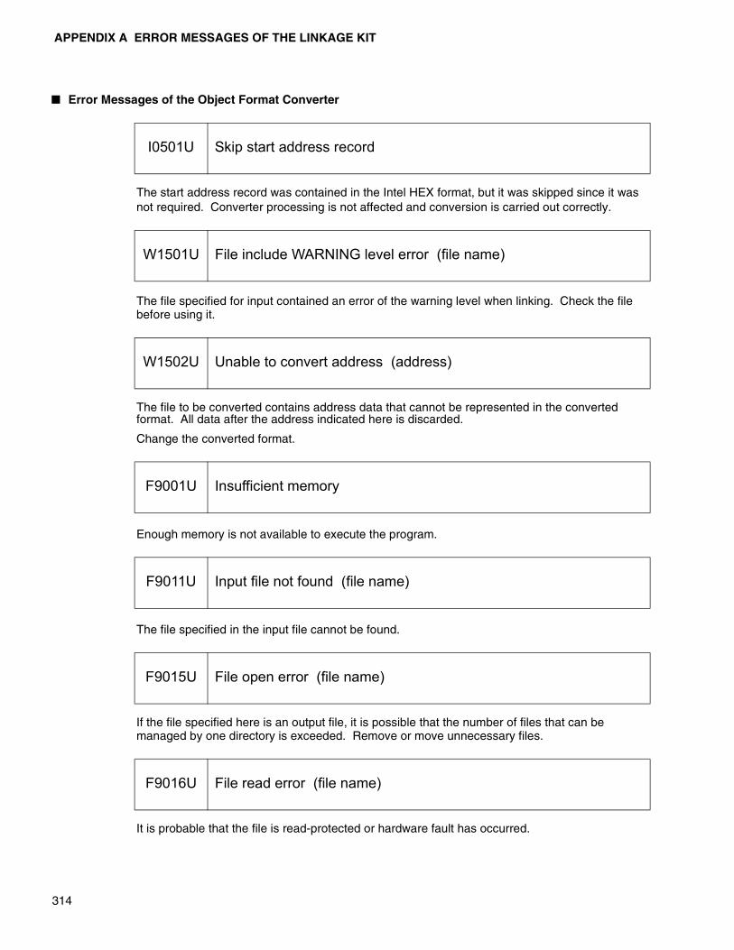
APPENDIX A ERROR MESSAGES OF THE LINKAGE KIT
314
� Error Messages of the Object Format Converter
The start address record was contained in the Intel HEX format, but it was skipped since it was not required. Converter processing is not affected and conversion is carried out correctly.
The file specified for input contained an error of the warning level when linking. Check the file before using it.
The file to be converted contains address data that cannot be represented in the converted format. All data after the address indicated here is discarded.
Change the converted format.
Enough memory is not available to execute the program.
The file specified in the input file cannot be found.
If the file specified here is an output file, it is possible that the number of files that can be managed by one directory is exceeded. Remove or move unnecessary files.
It is probable that the file is read-protected or hardware fault has occurred.
I0501U Skip start address record
W1501U File include WARNING level error (file name)
W1502U Unable to convert address (address)
F9001U Insufficient memory
F9011U Input file not found (file name)
F9015U File open error (file name)
F9016U File read error (file name)
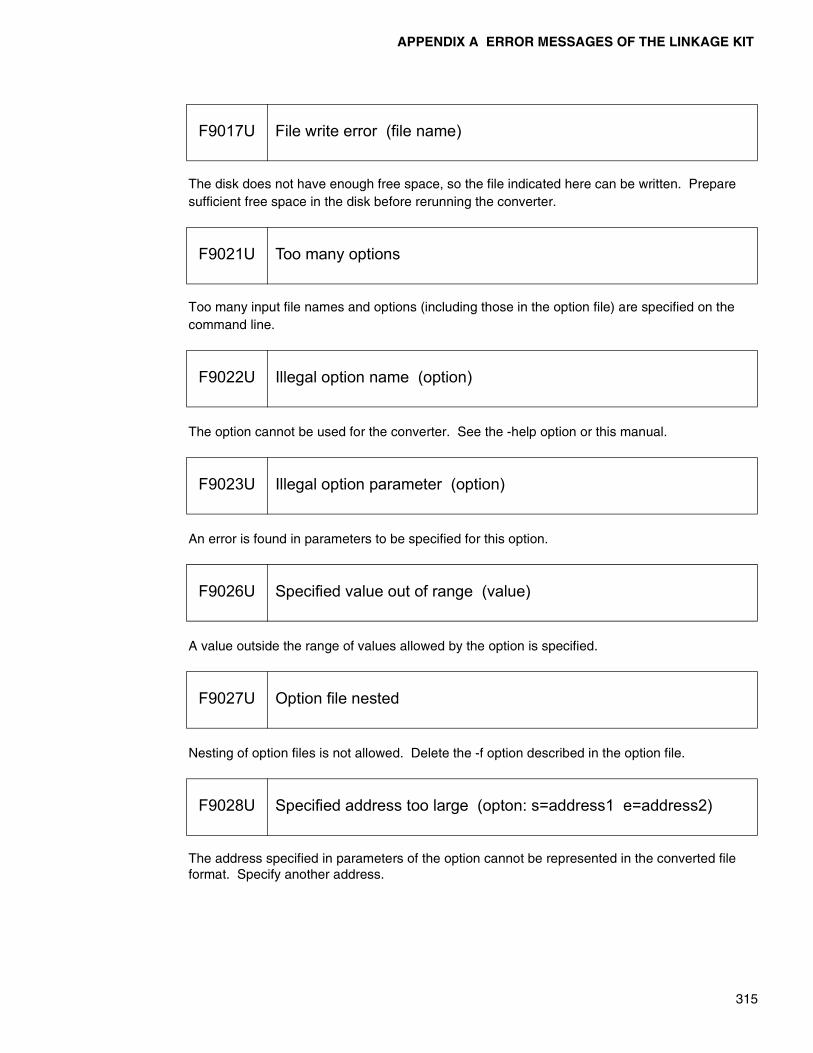
APPENDIX A ERROR MESSAGES OF THE LINKAGE KIT
315
The disk does not have enough free space, so the file indicated here can be written. Prepare sufficient free space in the disk before rerunning the converter.
Too many input file names and options (including those in the option file) are specified on the command line.
The option cannot be used for the converter. See the -help option or this manual.
An error is found in parameters to be specified for this option.
A value outside the range of values allowed by the option is specified.
Nesting of option files is not allowed. Delete the -f option described in the option file.
The address specified in parameters of the option cannot be represented in the converted file format. Specify another address.
F9017U File write error (file name)
F9021U Too many options
F9022U Illegal option name (option)
F9023U Illegal option parameter (option)
F9026U Specified value out of range (value)
F9027U Option file nested
F9028U Specified address too large (opton: s=address1 e=address2)

APPENDIX A ERROR MESSAGES OF THE LINKAGE KIT
316
The end address in parameters of the option is smaller than the start address.
Specify the name of an input file to be converted.
Only one input file can be specified. Specify either the file name indicated here or a file name specified before as the input file.
Since the output file name indicated here is the same as the input file name, processing cannot continue.
The input file is not in the object format to be processed.
A file of a different format is entered or the file is damaged.
A file is input which is not an absolute format load module output from the linker. Change the format of the file to the absolute format and then use it in the converter.
F9029U Start address opposite to end one (option: s=address1 e=address2)
F9030U Missing input file name
F9031U Multiple input file name (file name)
F9032U Output file name same as input one (file name)
F9033U Illegal file format (file name)
F9034U Not absolute load module file (file name)

APPENDIX A ERROR MESSAGES OF THE LINKAGE KIT
317
The output range is not specified.
Specify the range of output(-ran).
The output range exceeds the limit value.
The output file has the same name as that of another file.
The output file name indicated here is too long to be processed.
Make the specified file name shorter.
The message files used by the converter could not be opened.
Store both lkt_e.msg and lkt_a.msg in the predetermined directory.
If this error occurs, report it to Fujitsu immediately.
F9048U Missing output range
F9049U Output range exceeded
F9050U Output filename same as other output one (file name)
F9051U File name too long (file name)
F9998U File open failed (file name)
F9999U Internal error (identification information)

318
MEMO
319
APPENDIX B INTEL HEX AND INTEL EXTENDED HEX FORMAT
This appendix explains the following two formats of the Intel HEX formats.• Intel HEX format: Format set for the 8-bit MPU (i8080) • Intel extended HEX format: Format extended for the 16-bit MPU (i8086)
B.1 Common Format
B.2 Data Record (Intel HEX, Intel Extended HEX) Type:00
B.3 End Record (Intel HEX, Intel Extended HEX) Type:01
B.4 Extended Address Record (Intel Extended HEX) Type:02
B.5 Start Address Record (Intel Extended HEX) Type:03

APPENDIX B INTEL HEX AND INTEL EXTENDED HEX FORMAT
320
B.1 Common Format
The Intel (extended) HEX format consists of six fields, (a) to (f).Each field is set using the ASCII code. Field (g) is explained later.
� Common format
(a):
Indicates the start of a record. The character “:” (0x3A) is used.
(b):
Indicates the number of bytes in the data part of (e) .
Since the actual 1-byte data is represented by 2-byte ASCII code in this format, d1 and d2 in the above figure are counted as one.
11 indicates the high-order digits and 12 indicates the low-order digits. Values in the range of 0 - 255 can be set.
It is “00” - “FF” in ASCII notation and “0x3030” - “0x4646” in hexadecimal notation.
(c):
Indicates the address allocated to the first data if the contents of (e) are object data.
a1 indicates the high-order digits and a4 indicates the low-order digits. Values in the range of 0 - 65535 can be set.
It is “0000” - “FFFF” in ASCII notation and “0x30303030” - “0x46464646” in hexadecimal notation.
(d):
Indicates the record type.
00 : Data record (Intel HEX format, Intel extended HEX format)
01 : End record (Intel HEX format, Intel extended HEX format)
02 : Extended address record (Intel extended HEX format)
03 : Start address record (Intel extended HEX format)
(e):
This field depends on the record type of (d) . See the explanations of each record in B2 to B.5.
(f):
Checksum. Each 2-byte data of (b), (c), (d), and (e) represented in ASCII is converted into 1-byte hexadecimal data. Each byte without a sign is added regardless of overflow.
The two's complement of the result is calculated, then set as 2-byte ASCII data.
: 11 12 a1 a2 a3 a4 t1 t2 d1 d2 d3 d4 d* d* d* d* s1 s2
(a) (b) (c) (d) (e) (f) (g)
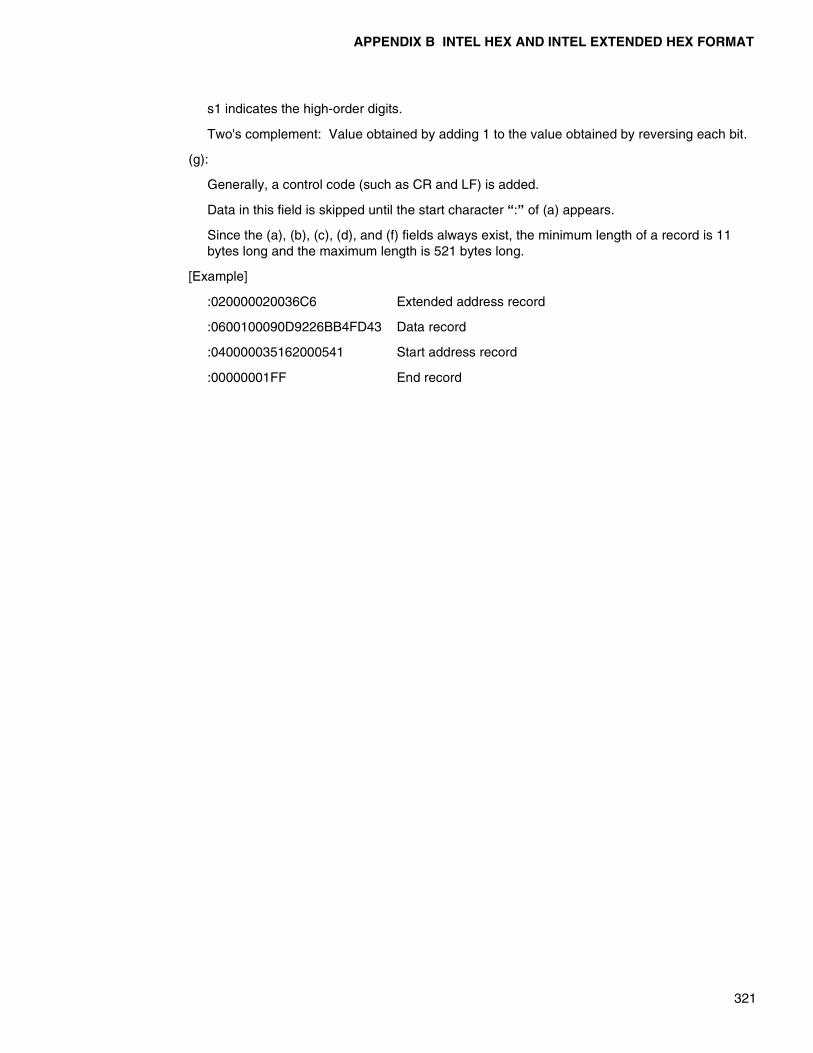
APPENDIX B INTEL HEX AND INTEL EXTENDED HEX FORMAT
321
s1 indicates the high-order digits.
Two's complement: Value obtained by adding 1 to the value obtained by reversing each bit.
(g):
Generally, a control code (such as CR and LF) is added.
Data in this field is skipped until the start character “:” of (a) appears.
Since the (a), (b), (c), (d), and (f) fields always exist, the minimum length of a record is 11 bytes long and the maximum length is 521 bytes long.
[Example]
:020000020036C6 Extended address record
:0600100090D9226BB4FD43 Data record
:040000035162000541 Start address record
:00000001FF End record
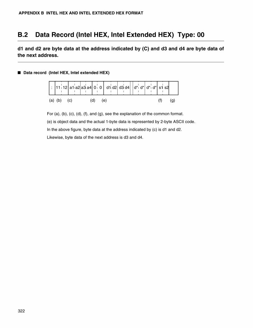
APPENDIX B INTEL HEX AND INTEL EXTENDED HEX FORMAT
322
B.2 Data Record (Intel HEX, Intel Extended HEX) Type: 00
d1 and d2 are byte data at the address indicated by (C) and d3 and d4 are byte data ofthe next address.
� Data record (Intel HEX, Intel extended HEX)
For (a), (b), (c), (d), (f), and (g), see the explanation of the common format.
(e) is object data and the actual 1-byte data is represented by 2-byte ASCII code.
In the above figure, byte data at the address indicated by (c) is d1 and d2.
Likewise, byte data of the next address is d3 and d4.
: 11 12 a1 a2 a3 a4 0 0 d1 d2 d3 d4 d* d* d* d* s1 s2
(a) (b) (c) (d) (e) (f) (g)
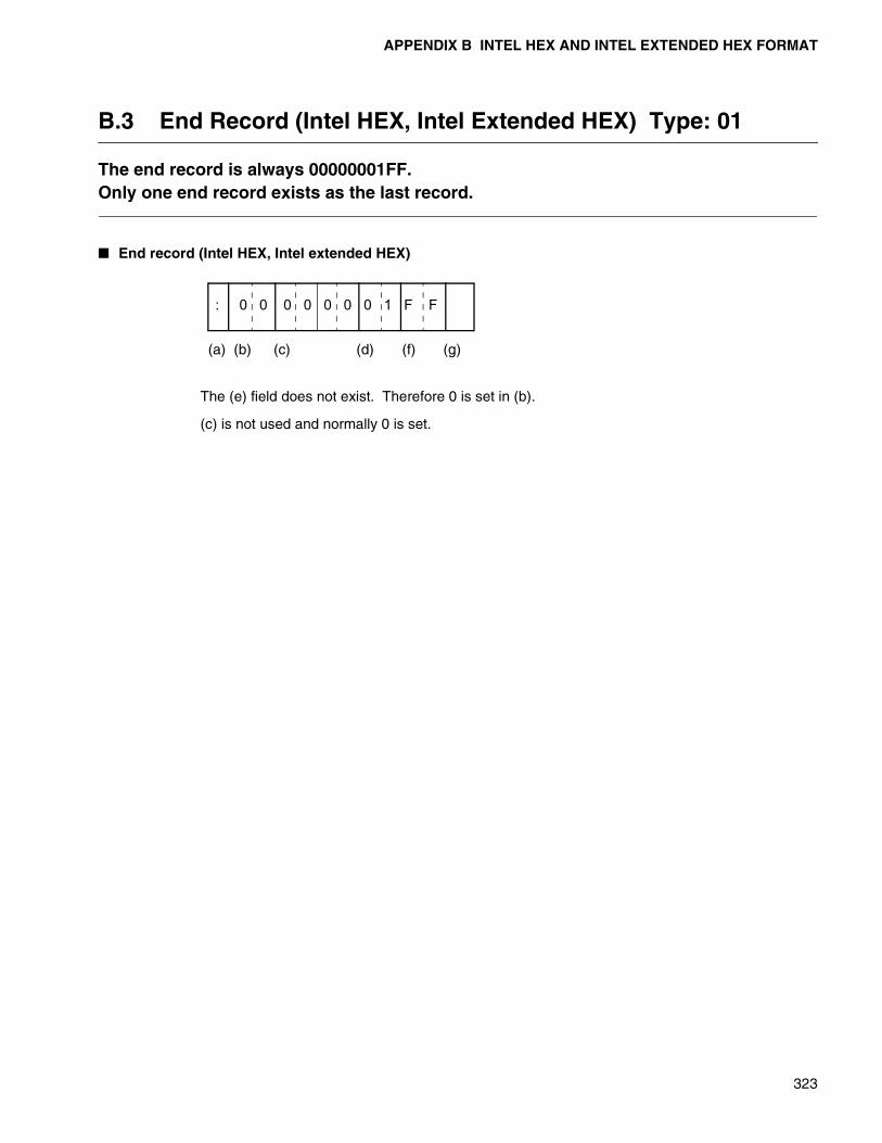
APPENDIX B INTEL HEX AND INTEL EXTENDED HEX FORMAT
323
B.3 End Record (Intel HEX, Intel Extended HEX) Type: 01
The end record is always 00000001FF.Only one end record exists as the last record.
� End record (Intel HEX, Intel extended HEX)
The (e) field does not exist. Therefore 0 is set in (b).
(c) is not used and normally 0 is set.
: 0 0 0 0 0 0 0 1 F F
(a) (b) (c) (d) (f) (g)

APPENDIX B INTEL HEX AND INTEL EXTENDED HEX FORMAT
324
B.4 Extended Address Record (Intel Extended HEX) Type: 02
If extended address code appears, the address of each byte data of the following datarecords is calculated according to the following formula.( ( PA x 0x10 ) + ( ( DA + DP ) MOD 0x10000 ) ) MOD 0x100000• PA: (e) field value of the record• DA: (c) field value of the record. Here, this value is a relative address.• DP: Value indicating the data position in the (e) field of the data record calculated bysetting the position of the first data to 0.
� Extended address record (Intel extended HEX)
(e) :
This is a paragraph address and the actual 2-byte data is represented as 4-byte ASCII code.
In the above figure, p1 indicates the high-order digits.
(c) :
This field is not used and normally 0 is set.
If extended address code appears, the address of each byte data of the following data records is calculated according to the following formula.
[( PA x 0x10 ) + [( DA + DP ) MOD 0x10000]] MOD 0x100000
• PA: (e) field value of the record
• DA: (c) field value of the record. Here, this value is a relative address.
• DP: Value indicating the data position in the (e) field of the data record calculated bysetting the position of the first data to 0.
This is the same method used for calculating the physical address in i8086. With the addition of extended address code, up to 20-bit addresses can be represented.
For the data records which appear before the extended address record, the address is calculated with the above PA setting as 0x0000.
: 0 2 0 0 0 0 0 2 p1 p2 p3 p4 s1 s2
(a) (b) (c) (d) (e) (f) (g)

APPENDIX B INTEL HEX AND INTEL EXTENDED HEX FORMAT
325
B.5 Start Address Record (Intel Extended HEX) Type: 03
This is a record to specify the start address of a program being executed.The start address is calculated using the following formula.( ( PA x 0x10 ) + IP ) MOD 0x100000• PA: (e1) field value of the record• IP: (e2) field value of the record
� Start address record (Intel extended HEX)
As shown in the above figure, (e) is divided into two fields. The paragraph address is set in (e1), and the offset value is set in (e2).
Both p1 and i1 are high-order digits.
(c) is not used and normally 0 is set.
The start address is calculated using the following formula.
[ ( PA x 0x10 ) + IP ] MOD 0x100000
• PA: (e1) field value of the record
• IP: (e2) field value of the record
This record can appear anywhere before the end record.
The appearance count is 0 or 1.
: 0 4 0 0 0 0 0 3 p1 p2 p3 p4 i1 i2 i3 i4 s1 s2
(a) (b) (c) (d) (e) (f) (g)

326
MEMO
327
APPENDIX C MOTOROLA S RECORD FORMAT
The S record format of Motorola always starts with the character “S” (0x53). Eighttypes from S0 to S9 are available (S4 and S6 are not used).
C.1 S0 Type (Header Record)
C.2 S1 Type (Data Record: 2-Byte Address)
C.3 S2 Type (Data Record: 3-Byte Address)
C.4 S3 Type (Data Record: 4-Byte Address)
C.5 S5 Type (Record to Manage the Number of Records)
C.6 S7 Type (Terminator Record)
C.7 S8 Type (Terminator Record)
C.8 S9 Type (Terminator Record)

APPENDIX C MOTOROLA S RECORD FORMAT
328
C.1 S0 Type (Header Record)
This record is used for comments.
� S0 type (header record)
This record consists of the above five fields (a)-(e).
The S0 type is called the header type and is placed at the start of a file ahead of each record of S1-S9. Each field is set in ASCII code.
(a):Type field. “S0” (0x5330) in ASCII code.
(b):Indicates the number of bytes in (c), (d), and (e).
Actual 1-byte data is represented as 2-byte ASCII code in this format and the number of characters in these fields divided by 2 is set.
11 indicates the high-order digits and 12 indicates the low-order digits. Values in the range of 0-255 can be set.
It is “00”-“FF” in ASCII notation and “0x3030”-“0x4646” in hexadecimal notation.
(c):This field is not used and normally “0000” in ASCII notation is set.
(d):Messages such as version number management information are set.
For the setting method, see the example below.
(e):Checksum.
Each 2-byte data of (b), (c), and (d) represented in ASCII notation is converted into 1-byte data in hexadecimal notation. Each byte without a sign is added regardless of overflow.
One’s complement of the result is calculated and then set as 2-byte ASCII code.
s1 indicates the high-order digits.
• One’s complement: value obtained by reversing each bit
(f):Generally, control code (such as CR and LF) is added.
Data in this field is skipped until the start character “S” of (a) appears.
[Example]
S 0 11 12 0 0 0 0 c1 c2 c3 c4 c* c* s1 s2
(a) (b) (c) (d) (e) (f)
2 bytes 2 bytes 4 bytes n bytes 2 bytes
S00600004844521B
Indicates ASCII character string “HDR”
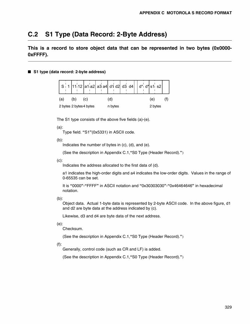
APPENDIX C MOTOROLA S RECORD FORMAT
329
C.2 S1 Type (Data Record: 2-Byte Address)
This is a record to store object data that can be represented in two bytes (0x0000-0xFFFF).
� S1 type (data record: 2-byte address)
The S1 type consists of the above five fields (a)-(e).
(a):Type field. “S1”(0x5331) in ASCII code.
(b):Indicates the number of bytes in (c), (d), and (e).
(See the description in Appendix C.1,“S0 Type (Header Record).”)
(c):Indicates the address allocated to the first data of (d).
a1 indicates the high-order digits and a4 indicates the low-order digits. Values in the range of 0-65535 can be set.
It is “0000”-“FFFF” in ASCII notation and “0x30303030”-“0x46464646” in hexadecimal notation.
(b):Object data. Actual 1-byte data is represented by 2-byte ASCII code. In the above figure, d1 and d2 are byte data at the address indicated by (c).
Likewise, d3 and d4 are byte data of the next address.
(e):Checksum.
(See the description in Appendix C.1,“S0 Type (Header Record).”)
(f):Generally, control code (such as CR and LF) is added.
(See the description in Appendix C.1,“S0 Type (Header Record).”)
S 1 11 12 a1 a2 a3 a4 d1 d2 d3 d4 d* d* s1 s2
(a) (b) (c) (d) (e) (f)
2 bytes 2 bytes4 bytes n bytes 2 bytes

APPENDIX C MOTOROLA S RECORD FORMAT
330
C.3 S2 Type (Data Record: 3-Byte Address)
The S2 type differs from the S1 type in (c) field size, and is a record to store object datawhich requires the 3-byte address.
� S2 type (data record: 3-byte address)
The S2 type differs from the S1 type in the above (c) field size, and is a record to store object data which requires the 3-byte address.
S 2 11 12 a1 a2 a3 a4 a5 a6 d1 d2 d3 d4 d* d* s1 s2
(a) (b) (c) (d) (e) (f)
2 bytes 2 bytes 4 bytes n bytes 2 bytes
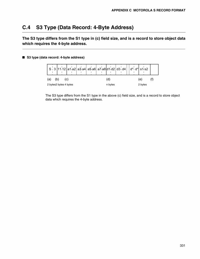
APPENDIX C MOTOROLA S RECORD FORMAT
331
C.4 S3 Type (Data Record: 4-Byte Address)
The S3 type differs from the S1 type in (c) field size, and is a record to store object datawhich requires the 4-byte address.
� S3 type (data record: 4-byte address)
The S3 type differs from the S1 type in the above (c) field size, and is a record to store object data which requires the 4-byte address.
S 3 11 12 a1 a2 a3 a4 a5 a6 a7 a8 d1 d2 d3 d4 d* d* s1 s2
(a) (b) (c) (d) (e) (f)
2 bytes2 bytes 4 bytes n bytes 2 bytes

APPENDIX C MOTOROLA S RECORD FORMAT
332
C.5 S5 Type (Record to Manage the Number of Records)
This record sets the number of records contained in a file and may not be specified. Itcan appear anywhere between S0 and S9.
� S5 type (record to manage the number of records)
The S5 type consists of the above four fields (a)-(e).
(a):Type field. "S5"(0x5335)in ASCII code.
(b):Indicates the number of bytes in (c) and (e).
(See the description in Appendix C.1,“S0 Type (Header Record).”)
(c):Indicates the number data records (S1, S2, S3) in a file.
n1 indicates the high-order digits and n4 indicates the low-order digits. Values in the range of 0-65535 can be set.
It is “0000”-“FFFF” in ASCII notation and “0x30303030”-“0x46464646” in hexadecimal notation.
(d):This field does not exist.
(e):Checksum.
(See the description in Appendix C.1,“S0 Type (Header Record).”)
(f):Generally, control code (such as CR and LF) is added.
(See the description in Appendix C.1,“S0 Type (Header Record).”)
S 5 0 3 n1 n2 n3 n4 s1 s2
(a) (b) (c) (e) (f)
2 bytes 2 bytes 4 bytes 2 bytes
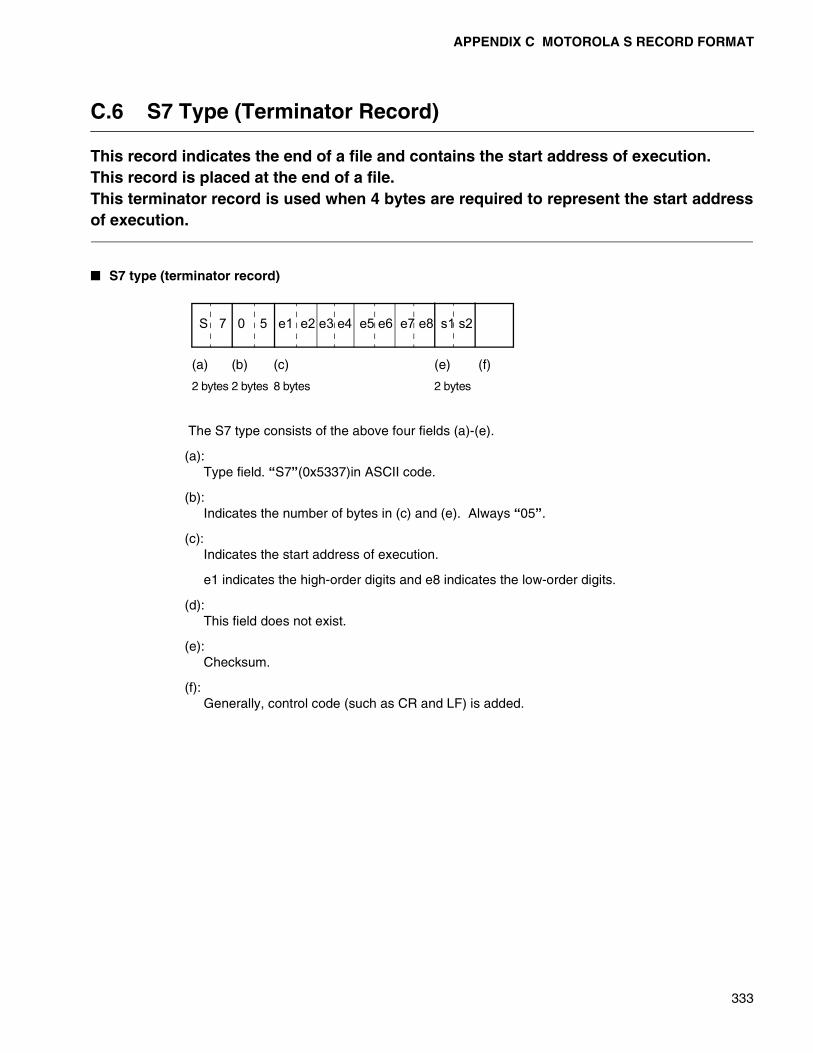
APPENDIX C MOTOROLA S RECORD FORMAT
333
C.6 S7 Type (Terminator Record)
This record indicates the end of a file and contains the start address of execution.This record is placed at the end of a file.This terminator record is used when 4 bytes are required to represent the start addressof execution.
� S7 type (terminator record)
The S7 type consists of the above four fields (a)-(e).
(a):Type field. “S7”(0x5337)in ASCII code.
(b):Indicates the number of bytes in (c) and (e). Always “05”.
(c):Indicates the start address of execution.
e1 indicates the high-order digits and e8 indicates the low-order digits.
(d):This field does not exist.
(e):Checksum.
(f):Generally, control code (such as CR and LF) is added.
S 7 0 5 e1 e2 e3 e4 e5 e6 e7 e8 s1 s2
(a) (b) (c) (e) (f)
2 bytes 2 bytes 8 bytes 2 bytes
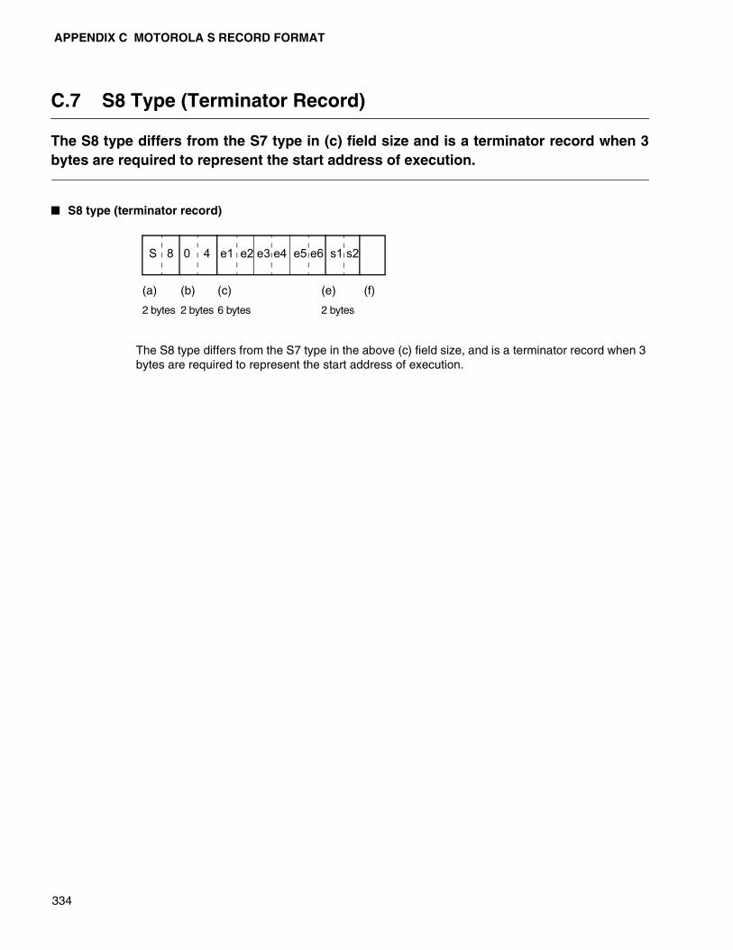
APPENDIX C MOTOROLA S RECORD FORMAT
334
C.7 S8 Type (Terminator Record)
The S8 type differs from the S7 type in (c) field size and is a terminator record when 3bytes are required to represent the start address of execution.
� S8 type (terminator record)
The S8 type differs from the S7 type in the above (c) field size, and is a terminator record when 3 bytes are required to represent the start address of execution.
S 8 0 4 e1 e2 e3 e4 e5 e6 s1 s2
(a) (b) (c) (e) (f)
2 bytes 2 bytes 6 bytes 2 bytes
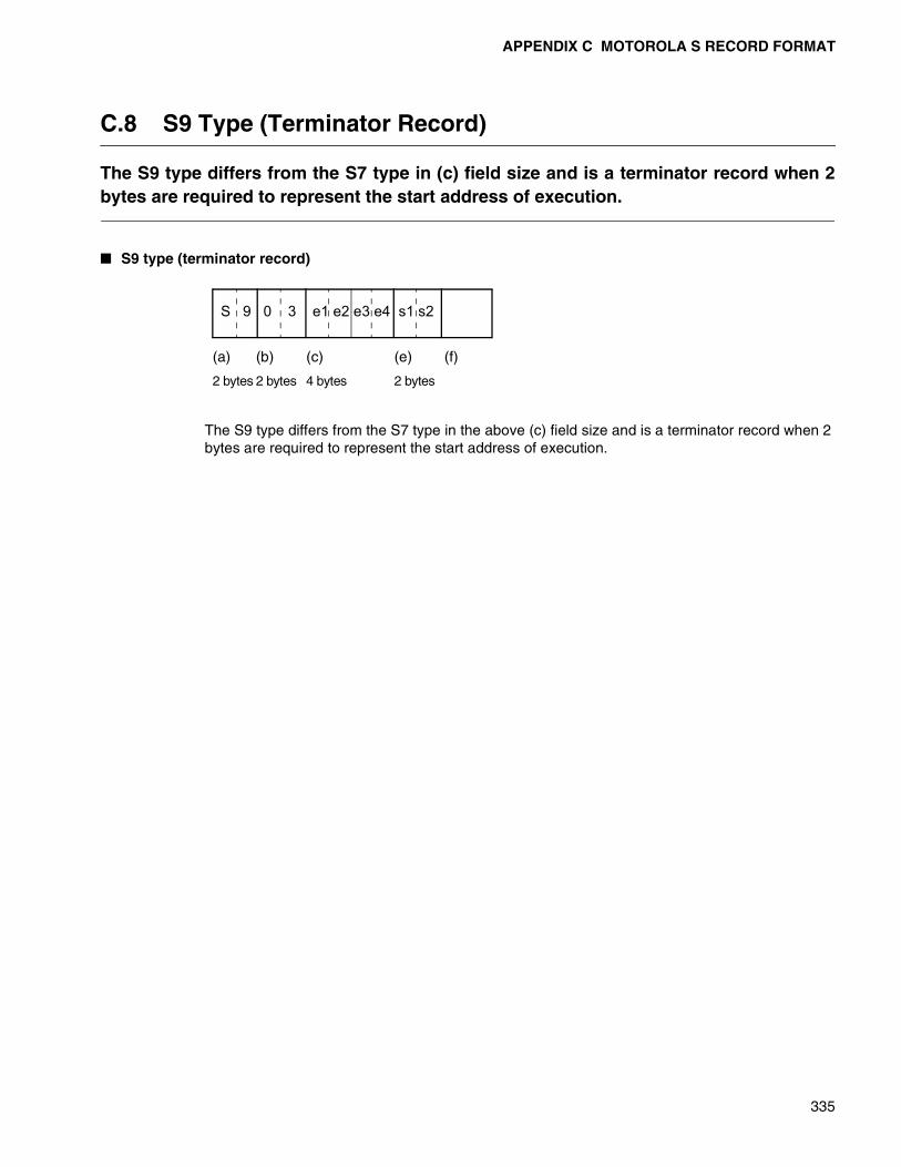
APPENDIX C MOTOROLA S RECORD FORMAT
335
C.8 S9 Type (Terminator Record)
The S9 type differs from the S7 type in (c) field size and is a terminator record when 2bytes are required to represent the start address of execution.
� S9 type (terminator record)
The S9 type differs from the S7 type in the above (c) field size and is a terminator record when 2 bytes are required to represent the start address of execution.
S 9 0 3 e1 e2 e3 e4 s1 s2
(a) (b) (c) (e) (f)
2 bytes 2 bytes 4 bytes 2 bytes

336
MEMO

337
APPENDIX D LIST OF LINKER OPTIONS
Appendix D lists the linker options.
� List of linker options
Attached Table D List of linker options
Function Option Remarks
Specification for outputting load module file name -o Default
Specification for debugging information output -g
Specification for deleting debugging information -Xg Default
Specification for outputting absolute format load module -a Default
Specification for outputting relative format load module -r
Map list file specification -m Default
Specification for inhibiting map list output -Xm
Canceling the omission of names displayed in the list -dt
Specification for outputting memory used information list -mmi
Specification of the number of digits in the list line -pw Default 132
Specification of the number of lines on one list page -pl Default 60
Specification for warning message output level -w
ROM area specification -ro
RAM area specification -ra
Section allocation -sc
Section group specification -gr
Pack link specification -pk FR family only
Register bank area specification -rgF2MC-16 family/F2MC-8L
family only
Automatic allocation specification -AL Default 0
Retrieval library file specification -l
Library retrieval path specification -L
Library specification for each symbol -el
Library retrieval inhibit specification -nl
Default library retrieval inhibit specification -nd
Entry address specification -e
Dummy setting of external symbol values -df
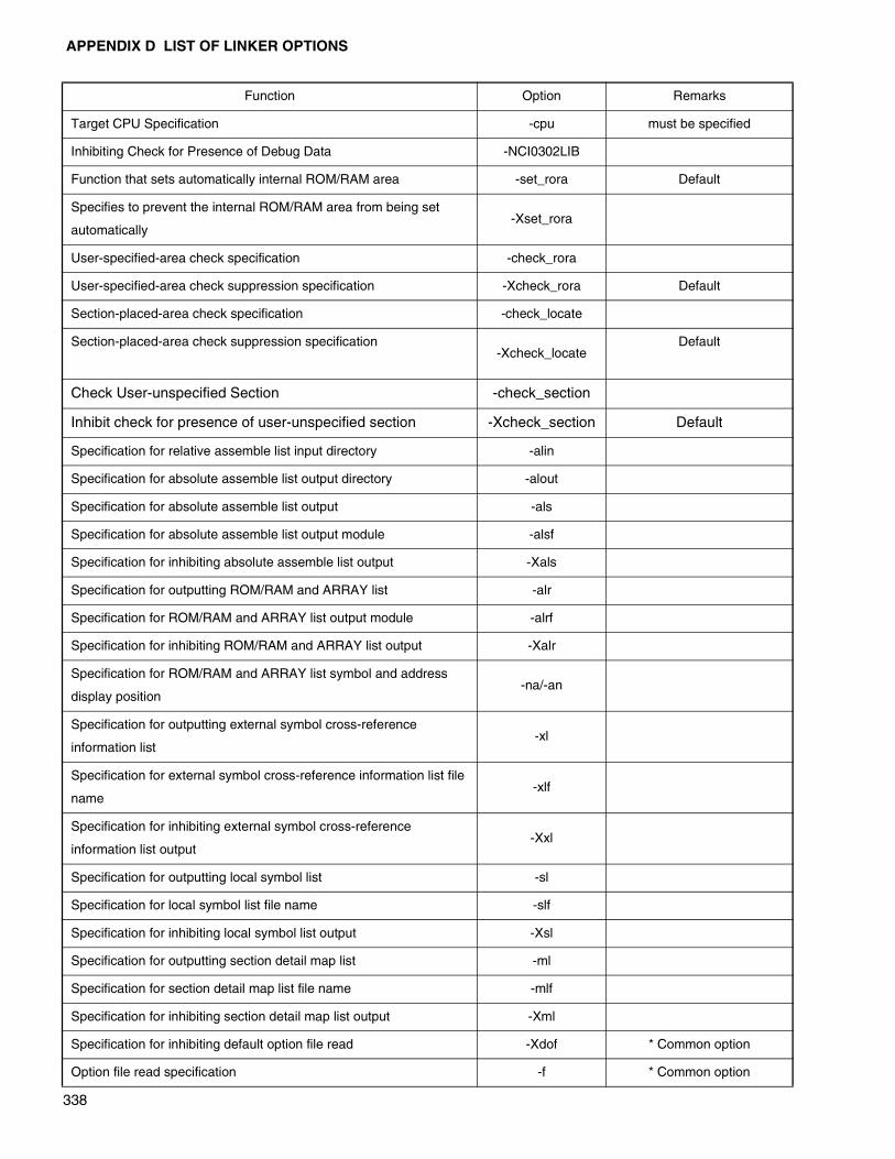
APPENDIX D LIST OF LINKER OPTIONS
338
Target CPU Specification -cpu must be specified
Inhibiting Check for Presence of Debug Data -NCI0302LIB
Function that sets automatically internal ROM/RAM area -set_rora Default
Specifies to prevent the internal ROM/RAM area from being set
automatically-Xset_rora
User-specified-area check specification -check_rora
User-specified-area check suppression specification -Xcheck_rora Default
Section-placed-area check specification -check_locate
Section-placed-area check suppression specification-Xcheck_locate
Default
Check User-unspecified Section -check_section
Inhibit check for presence of user-unspecified section -Xcheck_section Default
Specification for relative assemble list input directory -alin
Specification for absolute assemble list output directory -alout
Specification for absolute assemble list output -als
Specification for absolute assemble list output module -alsf
Specification for inhibiting absolute assemble list output -Xals
Specification for outputting ROM/RAM and ARRAY list -alr
Specification for ROM/RAM and ARRAY list output module -alrf
Specification for inhibiting ROM/RAM and ARRAY list output -Xalr
Specification for ROM/RAM and ARRAY list symbol and address
display position-na/-an
Specification for outputting external symbol cross-reference
information list-xl
Specification for external symbol cross-reference information list file
name-xlf
Specification for inhibiting external symbol cross-reference
information list output-Xxl
Specification for outputting local symbol list -sl
Specification for local symbol list file name -slf
Specification for inhibiting local symbol list output -Xsl
Specification for outputting section detail map list -ml
Specification for section detail map list file name -mlf
Specification for inhibiting section detail map list output -Xml
Specification for inhibiting default option file read -Xdof * Common option
Option file read specification -f * Common option
Function Option Remarks

APPENDIX D LIST OF LINKER OPTIONS
339
Specification for help message display -help * Common option
Specification for outputting version number/message -V * Common option
Specification for inhibiting version number/message output -XV * Common option
End message display specification -cmsg * Common option
Specification for End message display inhibit specification -Xcmsg * Common option
Specification to set end code to 1 when warning occurs -cwno * Common option
Specification to set end code to 0 when warning occurs -Xcwno * Common option
Function Option Remarks

340
MEMO
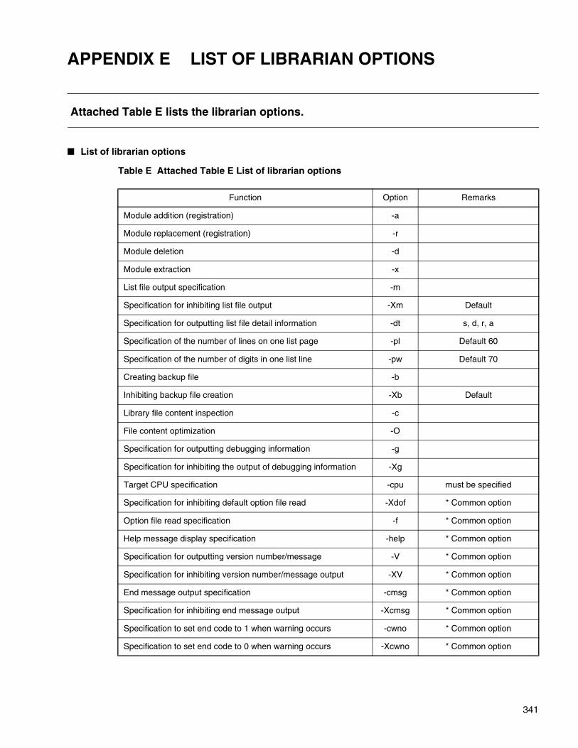
341
APPENDIX E LIST OF LIBRARIAN OPTIONS
Attached Table E lists the librarian options.
� List of librarian options
Table E Attached Table E List of librarian options
Function Option Remarks
Module addition (registration) -a
Module replacement (registration) -r
Module deletion -d
Module extraction -x
List file output specification -m
Specification for inhibiting list file output -Xm Default
Specification for outputting list file detail information -dt s, d, r, a
Specification of the number of lines on one list page -pl Default 60
Specification of the number of digits in one list line -pw Default 70
Creating backup file -b
Inhibiting backup file creation -Xb Default
Library file content inspection -c
File content optimization -O
Specification for outputting debugging information -g
Specification for inhibiting the output of debugging information -Xg
Target CPU specification -cpu must be specified
Specification for inhibiting default option file read -Xdof * Common option
Option file read specification -f * Common option
Help message display specification -help * Common option
Specification for outputting version number/message -V * Common option
Specification for inhibiting version number/message output -XV * Common option
End message output specification -cmsg * Common option
Specification for inhibiting end message output -Xcmsg * Common option
Specification to set end code to 1 when warning occurs -cwno * Common option
Specification to set end code to 0 when warning occurs -Xcwno * Common option

342
MEMO
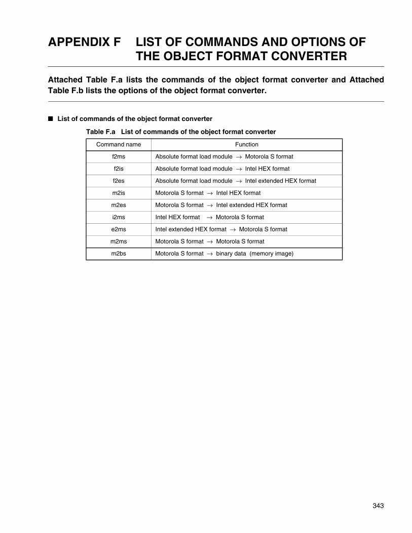
343
APPENDIX F LIST OF COMMANDS AND OPTIONS OF THE OBJECT FORMAT CONVERTER
Attached Table F.a lists the commands of the object format converter and AttachedTable F.b lists the options of the object format converter.
� List of commands of the object format converter
Table F.a List of commands of the object format converter
Command name Function
f2ms Absolute format load module → Motorola S format
f2is Absolute format load module → Intel HEX format
f2es Absolute format load module → Intel extended HEX format
m2is Motorola S format → Intel HEX format
m2es Motorola S format → Intel extended HEX format
i2ms Intel HEX format → Motorola S format
e2ms Intel extended HEX format → Motorola S format
m2ms Motorola S format → Motorola S format
m2bs Motorola S format → binary data (memory image)
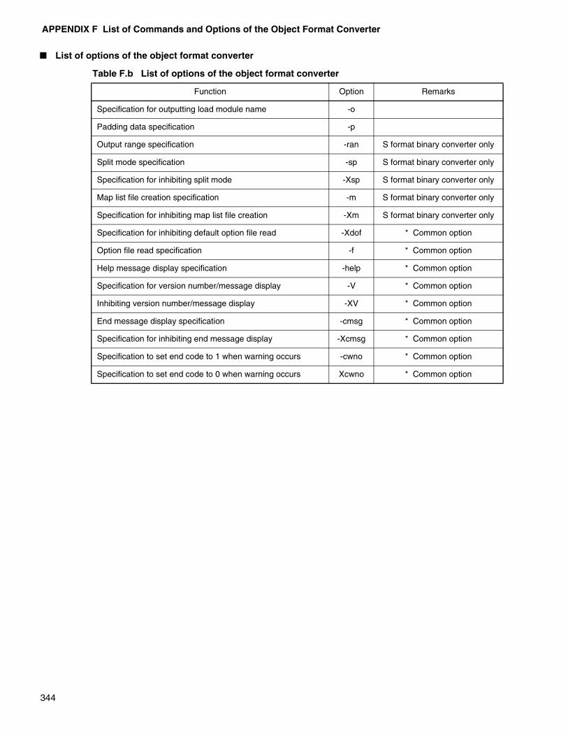
APPENDIX F List of Commands and Options of the Object Format Converter
344
� List of options of the object format converter
Table F.b List of options of the object format converter
Function Option Remarks
Specification for outputting load module name -o
Padding data specification -p
Output range specification -ran S format binary converter only
Split mode specification -sp S format binary converter only
Specification for inhibiting split mode -Xsp S format binary converter only
Map list file creation specification -m S format binary converter only
Specification for inhibiting map list file creation -Xm S format binary converter only
Specification for inhibiting default option file read -Xdof * Common option
Option file read specification -f * Common option
Help message display specification -help * Common option
Specification for version number/message display -V * Common option
Inhibiting version number/message display -XV * Common option
End message display specification -cmsg * Common option
Specification for inhibiting end message display -Xcmsg * Common option
Specification to set end code to 1 when warning occurs -cwno * Common option
Specification to set end code to 0 when warning occurs Xcwno * Common option
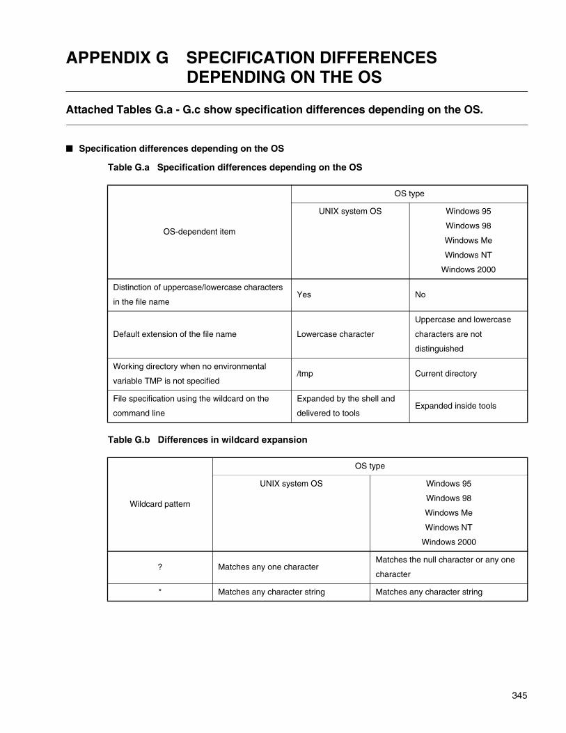
345
APPENDIX G SPECIFICATION DIFFERENCES DEPENDING ON THE OS
Attached Tables G.a - G.c show specification differences depending on the OS.
� Specification differences depending on the OS
Table G.a Specification differences depending on the OS
Table G.b Differences in wildcard expansion
OS-dependent item
OS type
UNIX system OS Windows 95
Windows 98
Windows Me
Windows NT
Windows 2000
Distinction of uppercase/lowercase characters
in the file nameYes No
Default extension of the file name Lowercase character
Uppercase and lowercase
characters are not
distinguished
Working directory when no environmental
variable TMP is not specified/tmp Current directory
File specification using the wildcard on the
command line
Expanded by the shell and
delivered to toolsExpanded inside tools
Wildcard pattern
OS type
UNIX system OS Windows 95
Windows 98
Windows Me
Windows NT
Windows 2000
? Matches any one characterMatches the null character or any one
character
* Matches any character string Matches any character string

APPENDIX G Specification Differences Depending on the OS
346
Table G.c Concrete examples of wildcard expansion
Wildcard pattern
OS type
UNIX system OS Windows 95
Windows 98
Windows Me
Windows NT
Windows 2000
a?.objal.obj matches.
a.obj does not match.
al.obj matches.
a.obj also matches.
a* al.obj, a.obj, and a.abs match. al.obj, a.obj, and al.abs match.
* abcz and abc.z match. abcz and abc.z match.
INDEX
INDEX
A
-a.................................................................... 95, 210a backup file......................................................... 219absolute assemble list file .................................... 170absolute assemble list output............................... 140absolute assemble list output directory................ 139absolute assemble list output inhibit .................... 142Absolute assemble list output module ................. 141absolute assemble list output module.................. 141absolute format assemble list .............................. 158absolute format assemble list output ..................... 91absolute format load modul.......................... 276, 277absolute format load module................................ 278absolute format load module output....................... 95Adding (registering) a module.............................. 210address .......................................................... 55, 106-AL ....................................................................... 114-alin ...................................................................... 138allocation................................................................ 91-alout .................................................................... 139-alr........................................................................ 143-alrf....................................................................... 144-als ....................................................................... 140-alsf ...................................................................... 141assemble lis ......................................................... 171assemble source list ............................................ 176automatic allocation ............................................. 114automatically locating section ................................ 69
B
-b.......................................................................... 219backup file............................................................ 220
C
-c .......................................................................... 221canceling the omission of name displayed
in the list .............................................................. 99-check_locate....................................................... 130-check_rora .......................................................... 127-check_section ..................................................... 135-cmsg ......................................................... 10, 29, 37command line..................................................... 5, 26common option ...................................................... 28control list part.............................................. 160, 161converter ...................................................... 241, 286
converting .............276, 277, 278, 280, 281, 282, 283-cpu.................................................86, 123, 206, 225CPU information .....................................................85CPU information file................................................85CPUs for which object may be mixed.............86, 206creating and editing a library ................................209cross-reference list ...............................................179-cwno ................................................................29, 39
D
-d ..........................................................................212data length in an output record.............................270debug data............................................................124debug information delete ........................................94debug information output ........................................93debugging information ............56, 200, 204, 223, 224default library retrieval inhibit ................................120default option file ..............................................30, 46deleting a module .................................................212-df .........................................................................122disk spac...............................................................234-dt ...................................................................99, 216
E
-e ..........................................................................121e2ms.....................................................................283-el..........................................................................118end code...........................................................39, 40end code value .........................................................8end message ..............................................10, 37, 38end status .................................................................8entry address..................................................60, 121error message ......................................................171example display of memory used information list
field list ...............................................................166example of a search .......................75, 76, 77, 78, 79example of location.........................66, 67, 68, 71, 73extended HEX format ...................................278, 283external symbol cross-reference information
list...............................................................158, 180external symbol cross-reference information list
file name.............................................................148external symbol cross-reference information list
output .................................................................147external symbol cross-reference information list
output inhibit.......................................................149external symbol value .....................................60, 122extracting a module ..............................................213
347

INDEX
F
-f .......................................................................29, 32f2es ......................................................................278f2is........................................................................277f2ms .....................................................................276FELANG...........................................................14, 16FETOOL...........................................................14, 17filename..................................................................13forced termination ....................................................7
G
-g ....................................................................93, 223-gr.........................................................................109
H
header format.......................................................172-help .................................................................29, 34help message...................................................11, 34HEX forma............................................................277HEX format...........................................280, 281, 282
I
i2ms......................................................................282identifier name........................................................12identifiers................................................................12intel extended HEX format ...................278, 281, 283intel HEX format ...................................277, 280, 282internal ROM/RAM area...............................125, 126
L
-L ..........................................................................117-l ...........................................................................116-len ...............................................................269, 270LIB896....................................................................18LIB907....................................................................18LIB911....................................................................18libraria ..................................................................234librarian ........................................................199, 208library .......................................................55, 59, 118Library control ........................................................91library file ........................59, 200, 201, 203, 205, 221library files are individually specified ......................80library retrieval inhibit ...........................................119library retrieval path..............................................117library to be searched.............................................74link control ..............................................................91link list file.....................................................158, 159link option ...............................................................91
linkage kit ................................................................. 4linker ................................................................ 52, 54linker reservation symbol ..................................... 188linker restriction.................................................... 188links of section ....................................................... 65list display example.............................. 161, 163, 169list file ............................................................. 56, 228list file name........................................................... 56list of linker option .................................................. 88list output format .................................. 160, 162, 168list output overview .............................. 229, 230, 231load module converter ......................................... 241load module file name............................................ 56local symbol information list ......................... 158, 182local symbol information list file name ................. 151local symbol information list output inhibit............ 152location address......................................... 58, 70, 72location destination ................................................ 72
M
-m................................................... 97, 214, 255, 259m2es .................................................................... 281m2is ..................................................................... 280map list file ........................................... 255, 259, 261map list file memory used information list (-mmi),
output specification of........................................ 100map list file name................................................... 97map list output inhibit ............................................. 98map list part ................................................. 162, 163memory used information list field list output
format ................................................................ 164message ................................................................ 35message output ..................................................... 36mixing of object .............................................. 86, 206-ml ........................................................................ 153-mlf ....................................................................... 154motorola S format ................ 276, 280, 281, 282, 283
N
-na,-an.................................................................. 146-NCI0302LIB ........................................................ 124-nd........................................................................ 120-nl ......................................................................... 119note and evaluation................................................ 24number of column per line of a list ....................... 218number of digit in the list line ............................... 101number of line on one list page............................ 102number of line per page of a list........................... 217
348
INDEX
O
-O ......................................................................... 222-o.................................................................... 92, 245object content list output ........................................ 91object file................................................................ 56object file converter.............................................. 240object file format................................................... 188object format converter ................................ 242, 244object tool............................................................. 287OPT.................................................................. 14, 20OPT896.................................................................. 19OPT907.................................................................. 19OPT911.................................................................. 19optimizing the content of a file ............................. 222optio ....................................................................... 24option ................. 22, 25, 28, 208, 234, 244, 254, 268option file........................................ 32, 42, 43, 44, 45option parameters .................................................. 23other option .......................................................... 209output a list file ............................................. 214, 215output detailed information of a list file................. 216output file name ................................................... 245output format.......................................................... 56output list................................................................ 91output load module file name................................. 92output message ..................................................... 91output module ........................................................ 91output range................................. 255, 256, 269, 271output record................................................ 269, 272output record data length ..................................... 269outputting a list ..................................................... 209
P
-p.......................................................................... 247pack link ............................................................... 110padding ................................................................ 247parameter............................................................... 22-pk ........................................................................ 110-pl ................................................................. 102, 217precaution ............................................................ 234-pw ............................................................... 101, 218
R
-r..................................................................... 96, 211RA .......................................................................... 58-ra......................................................................... 105RAM area............................................................. 105-ran............................................... 255, 256, 269, 271
register bank area.................................................112Relative assemble list input directory ...................138relative format load module output .........................96Replacing (registering) a module..........................211replacing (registering) a module ...........................211restriction ......................................................234, 286retrieval library file ................................................116-rg .........................................................................112-ro .........................................................................104ROM .......................................................................58ROM and RAM area ...............................................81ROM area .............................................................104ROM/RAM and ARRAY list ..................................174ROM/RAM and ARRAY list output .......................143ROM/RAM and ARRAY list output inhibit .............145ROM/RAM and ARRAY list output module...........144ROM/RAM and ARRAY list symbol and address
display position...................................................146ROM/RAM area name ............................................85
S
S format ................................276, 280, 281, 282, 283S format adjuster ..........................241, 264, 265, 268S format binary converte ......................................254S format binary converter .....................241, 250, 286-S1/-S2/-S3...................................................269, 272-sc.........................................................................106searching a library file.............................................74searching and protecting a file..............................209section ..............................................................55, 58section allocation detailed information list ............184section allocation order.........................................106section combination attribute..................................62section content .......................................................62section detail map list ...........................................158section detail map list name .................................154section detail map list output ................................153section detail map list output inhibit ......................155section group ........................................................109section identification ...............................................63section information list ..........................................178section location attribute.........................................62section name ..........................................................62section to be transferred from ROM to RAM ....82, 83section type ............................................................72section-placed-area ......................................130, 134-set_rora ...............................................................125shared combination of section ................................64simple connection combination of section ..............64
349

INDEX
-slf ........................................................................151-sp ................................................................255, 257split mode.....................................250, 255, 257, 258startup message.................................................9, 56symbol list part .............................................168, 169symbol value ....................................................55, 60
T
target CPU ...................................................123, 225terminatio .................................................................7termination message..............................................57TMP..................................................................14, 15
U
user-specified-area ......................................127, 129user-unspecified section ..............................135, 137using the wild card ...............................................189
V
-V..................................................................9, 29, 35variable with initial value ......................................190version number ................................................35, 36
W
-w .........................................................................103warning.............................................................39, 40warning check level................................................56warning message output level..............................103
X
-x ..........................................................................213-Xalr......................................................................145-Xals .....................................................................142-Xb........................................................................220-Xcheck_locate.....................................................134-Xcheck_rora........................................................129-Xcheck_section...................................................137-Xcmsg .............................................................29, 38-Xcwno .............................................................29, 40-Xdof.................................................................29, 30-Xg..................................................................94, 224-xl .........................................................................147-xlf ........................................................................148-Xm.................................................98, 215, 255, 261-Xml......................................................................155-Xset_rora ............................................................126-Xsl .......................................................................152-Xsp..............................................................255, 258
-XV................................................................... 29, 36-Xxl....................................................................... 149
350