Embed Size (px)
Citation preview
NASA TP 1035 , c . 1
NASA Technical Paper 1035
Friction and Wear Behavior of Single-Crystal Silicon Carbide in Contact With Titanium
Kazuhisa Miyoshi and Donald H. Buckley
SEPTEMBER 1977
NASA
I
https://ntrs.nasa.gov/search.jsp?R=19770025368 2018-05-14T09:13:26+00:00Z
TECH LIBRARY KAFB, NM
NASA Technical Paper 1035
Friction and Wear Behavior of Single-Crystal Silicon Carbide in Contact With Titanium
Kazuhisa Miyoshi Kanazawa University Kanazawa, Japan
and Donald H. Buckley Lewis Research Center Cleveland, Ohio
National Aeronautics and Space Administration
Scientific and Technical Information Office
1977
FRICTION AND WEAR BEHAVIOR OF SINGLE-CRYSTAL SILICON
CAR BIDE IN CONTACT WITH TITANIUM
by Kazuhisa Miyoshi" and Donald H. Buckley
Lewis Research Center
SUMMARY
An investigation was conducted to examine the friction and wear behavior of single- crystal silicon carbide in contact with titanium and the nature of interfacial transfer. Sliding friction experiments were conducted with a polycrystalline titanium rider sliding on a single-crystal silicon carbide (0001) surface in the (1070) directions. Sliding was both in argon at atmospheric pressure and in high vacuum N/m ). Applied loads varied up to 50 grams. Auger emission spectroscopy analysis was used to monitor the surface in high vacuum.
2
The resul ts of the investigation indicate that the friction coefficient is grea te r in vacuum than in argon and that this is due to the greater adhesion o r adhesive transfer in vacuum. Thin films of silicon carbide transferred to the titanium and titanium also adhered to the silicon carbide both in argon at atmospheric pressure and in high vacuum. Cohesive bonds fractured on both the silicon carbide and titanium surfaces. Wear debris of silicon carbide created by fracture plowed the silicon carbide surface in a plastic manner. The friction characteristics of titanium in contact with silicon carbide were sensitive to the surface asper i t ies on silicon carbide, and the friction coefficients were higher for a rough surface of silicon carbide than for a smooth one. The difference in friction results w a s due to plastic deformation (plowing of titanium).
INTRODUCTION
For many years , it has been known that silicon carbide has outstanding mechanical and physical properties. Silicon carbide is at the same t ime a very old ceramic (grinding wheels) and also one of the newest (turbine blades, vanes, and shrouds in gas turbine engines). The considerable recent interest in si l icon carbide in the field of tribology has been stimulated mainly by one of its key properties, that is, its high wear res is tance
* Assis tant Professor of Precision Engineering, Kanazawa University, Kanazawa, Japan; National Research Council - National Aeronautics and Space Administration Research Associate.
I
under a variety of exacting environmental conditions. But, the tribophysical properties of silicon carbide in contact with metals, ceramics, and polymers are not clearly under- stood. Very little experimental work has been done with silicon carbide.
Silicon carbide in contact with silicon carbide exhibits lower friction than unlubri- cated metals and retains it to much higher temperatures (refs. 1 and 2). Furthermore, the effect of crystallographic orientation and load on the Knoop microhardness of single- crystal silicon carbide has been investigated (ref. 3). Nevertheless, there is a great lack of fundamental information about the mechanism of friction and the mechanical behavior.
The present investigation was conducted to examine the friction and wear behavior of single-crystal silicon carbide in contact with titanium and the nature of interfacial transfer. All experiments were conducted with light loads of 5 to 50 grams, at a sliding velocity of 0 .7 mm/min in a vacuum of N/m o r at a sliding velocity of 3 mm/min in argon, on the (0001) basal plane in the (1010) directions. All experiments were con- ducted at room temperature.
2
MATERIALS
The single-crystal silicon carbide platelets in these experiments were a 99.9- percent-pure compound of silicon and carbon. Silicon carbide had a hexagonal crystal structure with the most commonly occurring unit cell dimensions of a = 3.0817 and c = 15.1183 A. The unit cell contained two interpenetrating close-packed atomic arrays, one of silicon and the other of carbon displaced by 1/4-layer spacing along the c-axis. The silicon atoms thus occupied the tetrahedral locations in the array of carbon atoms and conversely. Hence, the basic unit of the structure can be considered to be a plane of te t rahedra, arbi t rar i ly Sic4 o r CSi4. The c-direction was perpendicular to the sliding interface, with the basal planes therefore parallel to the interface.
The titanium polycrystal was 99.97 percent pure and had a hexagonal close-packed crystal structure.
APPARATUS
Two apparatuses were used in this investigation. One was a system capable of applying load and measuring friction in argon. The mechanism for measuring friction is shown schematically in figure l(a). The beam contained one flat machined normal to the direction of friction application. The end of the rod contained the polycrystalline titanium pin specimen. Load was applied by placing deadweights on a pan on top of the
2
rod. Under an applied load, the friction force was sensed by the strain gage. The second apparatus was a vacuum system capable of measuring adhesion, load,
and friction and capable of Auger and low-energy electron diffraction (LEED) surface analysis. The mechanism for applying load and measuring adhesion and friction is shown schematically in figure l(b). A gimbal-mounted beam projected into the vacuum system. The beam contained two flats machined normal to each other with strain gages mounted thereon. The end of the rod contained the polycrystalline titanium pin specimen. The load applied by moving the beam toward the flat plate was measured by the strain gage. Tangential motion of the pin along the flat plate was accomplished through the gimbal as- sembly. Under an applied load, the friction force was sensed by the strain gage normal to that used to measure the applied load. Pin sliding was in the vertical direction of fig- u r e l(b).
The vacuum apparatus in which the components of figure l(b) were contained also had a LEED diffraction system and an Auger spectrometer. The electron beam of both could be focused on any flat-plate site desired. This was accomplished with a flat-plate manipulation device. The vacuum system was a conventional vacsorb and ion-pumped system capable of readily achieving pressures of 1 . 3 3 ~ 1 0 - ~ N/m (10-l' t o r r ) as meas- ured by a nude ionization gage within the specimen chamber. Sublimation pumping was also used to more rapidly achieve the pressure desired.
2
EXPERIMENTAL PROCEDURE
The polycrystalline titanium surface was hemispherical and w a s polished with ap- proximately 1- ym-diameter aluminum oxide (A1203) powder. The radius of the titanium r ider was 0.79 mm (1/32 in. ). The titanium was then chemically polished. The sur - faces were r insed with water and 200-proof ethyl alcohol.
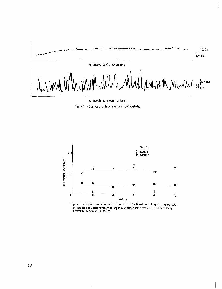
The single-crystal silicon carbide surfaces were used both in the original as-grown platelet condition (rough surfaces) and as surfaces mechanically polished with a 1- ym A1203 powder (smooth surfaces) (fig. 2) .
and the system was evacuated. It was baked out overnight, after which the pressure was in the 10-8-N/m range. Argon gas was bled into the vacuum system to a pressure of 1 . 3 N/m . A 1000-volt direct-current potential was applied to the specimen, and it was sputter bombarded for 30 minutes. After sputtering, the surface was examined with Auger emission spectroscopy to establish the surface cleanliness. If the surface was not clean, the sputtering process was repeated. The silicon carbide was placed in a tantalum harness for surface sputter cleaning. All fr iction experiments in vacuum were conducted with the system reevacuated to a pressure of N/m .
For the experiments in vacuum, the specimens were placed in the vacuum chamber
2 2
2
3
RESULTS AND DISCUSSION
Friction and Wear in Argon at Atmospheric Pressure
Friction of titanium sliding on silicon carbide. - Sliding friction experiments were conducted with the titanium specimen in contact with both smooth and rough silicon car- bide (0001) surfaces. Surface profiles are shown in f igure 2. The friction coefficients measured at various loads for the titanium rider in sliding contact with the silicon car- bide are presented in figure 3. The data of figure 3 show marked differences in friction behavior with the smooth and rough surfaces. The rough surface of silicon carbide pro- duces higher measured friction coefficients. Surface asperities, as shown in figure 2, also have a marked effect on the f r ic t ion force t races (fig. 4). The friction force traces for the smooth surface of silicon carbide are characterized by randomly fluctuating be- havior, with no evidence of stick-slip behavior. On the other hand, the traces for the rough surface are characterized by marked stick-slip behavior.
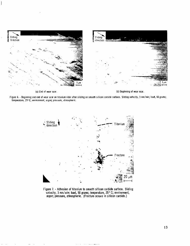
Wear of titanium -~ sliding ~~ on smooth - silicon carbide. - Titanium sliding on smooth silicon carbide results in the transfer of silicon carbide to the titanium, as shown in figure 5. Figures 5(a) and (b) are scanning electron micrographs of the r ider wear scar on titanium after it slid on a smooth carbide surface. In figure 5(a) to the left-top of the wear scar is the beginning of the contact area with silicon carbide, the midsection in the figure is the end of the contact area. A scanning electron micrograph of the end of the wear scar , where many t ransfer f i lms of silicon carbide are evident, and an X-ray energy-dispersive analysis for silicon on the titanium surface are shown in figures 5(b) and (c), respectively. The concentrations of white spots in figure 5(c) correspond to those locations in figure 5(b) where transfer is evident. The copius amount of thin sili- con carbide film shown on the titanium in figure 5 was the result of a single pass of the t i tanium rider across the si l icon carbide f lat surface. After these f i lms were formed in sliding, that is, at the end of the wear s c a r , a large number of deep grooves appeared on the surface of the titanium, as shown in figure 6(a). These grooves were produced in a plastic manner by the plowing of hard asperit ies of silicon carbide transferred to the titanium. Such a transfer f i lm is still evident at the beginning of the wear scar in the scanning electron micrograph (fig. 6(b)).
_ _
Examining the wear t rack on the silicon carbide surface caused by titanium sliding against it revealed evidence of f racture in silicon carbide at a higher load of 50 g (fig. 7 ) and t ransfer of titanium to the silicon carbide.
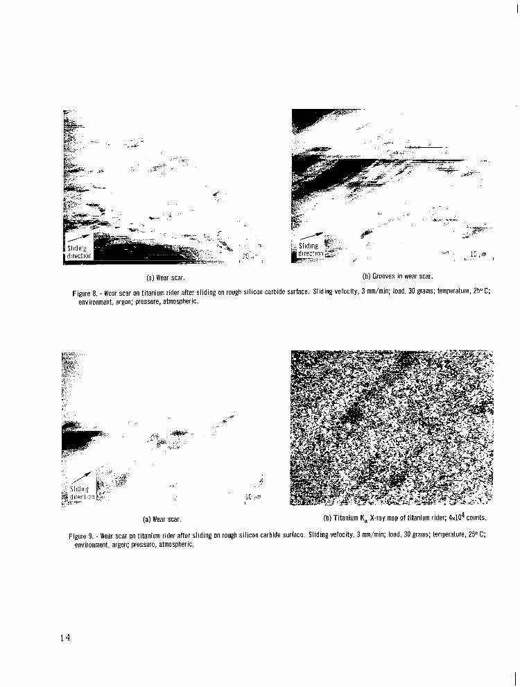
Wear of titanium sliding on rough silicon carbide. - When titanium slid on rough silicon carbide, a large number of plastically deformed grooves appeared on the titanium surface, and titanium was transferred to the randomly distributed asperities of the sili- con carbide, as shown in figures 8 to 10. Figure 8 shows scanning electron micrographs of the r ider wear scar created by titanium sliding on a rough silicon carbide surface
4
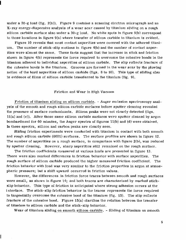
under a 30-g load (fig. 2(b)). Figure 9 contains a scanning electron micrograph and an X-ray energy-dispersive analysis of a wear scar caused by titanium sliding on a rough silicon carbide surface also under a 30-g load. No white spots in figure 9(b) correspond to those locations in figure 9(a) where transfer of silicon carbide to titanium is evident.
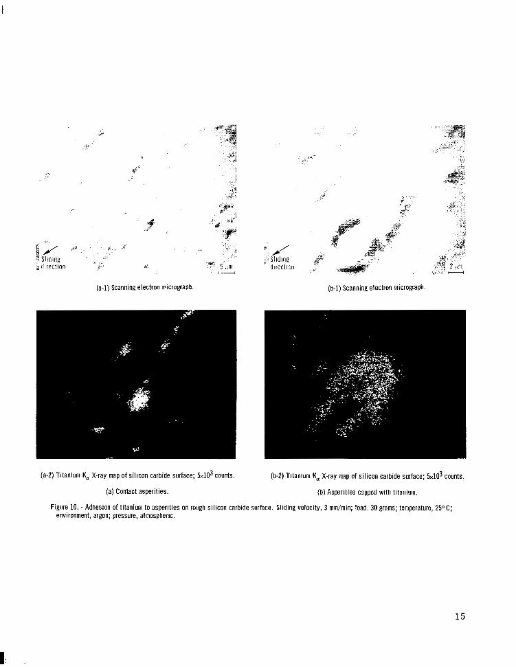
Figure 10 reveals that most contact asperities were covered with the adhered titani- um. The number of stick-slip motions in figure 4(b) and the number of contact asper- i t ies were almost the same. These facts suggest that the increase in stick and friction shown in figure 4(b) represents the force required to overcome the cohesive bonds in the titanium adhered to individual asperities of silicon carbide. The slip reflects fracture of the cohesive bonds in the titanium. Grooves are formed in the wear s c a r by the plowing action of the hard asperit ies of silicon carbide (figs. 8 to 10). This type of sliding also is evidence of fi lms of silicon carbide transferred to the titanium (fig. 9).
Friction and Wear in High Vacuum
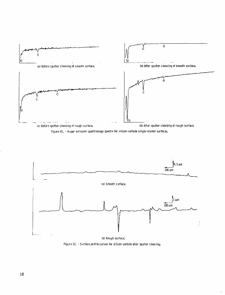
Friction of titanium sliding on silicon carbide. - Auger emission spectroscopy anal- ysis of the smooth and rough silicon carbide surfaces before sputter cleaning revealed the presence of surface contaminants. Silicon peaks were not clearly detected (figs. ll(a) and (c)). After these same silicon carbide surfaces were sputter cleaned by argon bombardment for 60 minutes, the Auger spectra of figures l l (b) and (d) were obtained. In these spectra, silicon and carbon peaks are clearly seen.
and rough silicon carbide (0001) surfaces. The surface profiles are shown in figure 12. The number of asperit ies on a rough surface, in comparison with figure 2(b), was reduced by sputter cleaning. However, sharp asperities still remained on the rough surface.
Sliding friction experiments were conducted with titanium in contact with both smooth
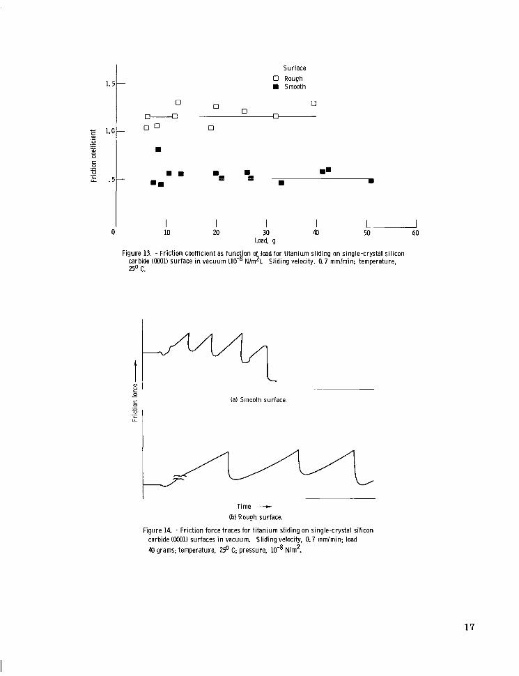
The friction coefficients measured at various loads are presented in figure 13. There were also marked differences in friction behavior with surface asperities. The rough surface of silicon carbide produced the higher measured friction coefficient. The friction behavior with load was very similar to the friction properties in argon at atmos- pheric pressure; but a shift upward occurred in friction values.
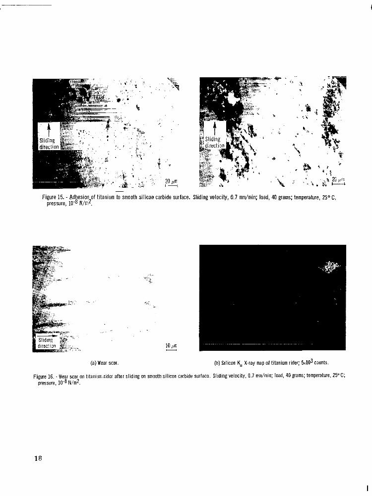
However, the differences in friction force traces between smooth and rough surfaces were small , as shown in figure 14; and both traces are characterized by marked stick- slip behavior. This type of friction is anticipated where strong adhesion occurs at the interface. The stick-slip friction behavior in the t races represents the force required to tangentially overcome the cohesive bond of the titanium (fig. 15). The slip reflects f racture of the cohesive bond. Figure 15(a) clarifies the relation between the t ransfer of titanium to silicon carbide and the stick-slip behavior.
Wear of titanium sliding ~~ on smooth silicon carbide. - Sliding of titanium on smooth
5
I
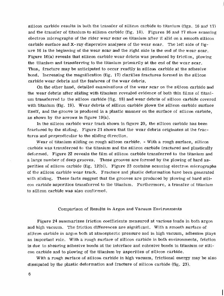
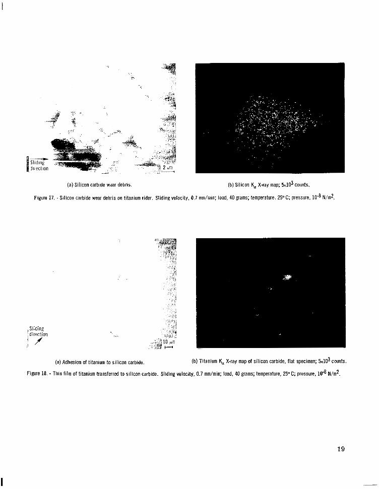
silicon carbide results in both the transfer of silicon carbide to titanium (figs. 16 and 17) and the transfer of titanium to silicon carbide (fig. 18). Figures 16 and 17 show scanning electron micrographs of the r ider wear scar on titanium after it slid on a smooth silicon carbide surface and X-ray dispersive analyses of the wear scar. The left side of fig- u r e 16 is the beginning of the wear s c a r and the right side is the end of the wear scar. Figure 16(a) reveals that si l icon carbide wear debris was produced by friction, plowing the titanium and transferring to the titanium primarily at the end of the wear scar . Thus, fracture may be anticipated to occur readily in silicon carbide at the adhesive bond. Increasing the magnification (fig. 17) clarifies fractures formed in the silicon carbide wear debris and the features of the wear debris.
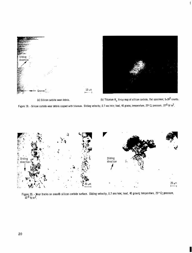
On the other hand, detailed examinations of the wear scar on the silicon carbide and the wear debris after sl iding with titanium revealed evidence of both thin films of titani- um transferred to the silicon carbide (fig. 18) and wear debris of silicon carbide covered with titanium (fig. 19). Wear debris of silicon carbide plows the silicon carbide surface itself, and the groove is produced in a plastic manner on the surface of silicon carbide, as shown by the arrows in figure 19(a).
In the silicon carbide wear track shown in figure 20, the silicon carbide has been fractured by the sliding. Figure 21 shows that the wear debris originates at the frac- tu res and perpendicular to the sliding direction.
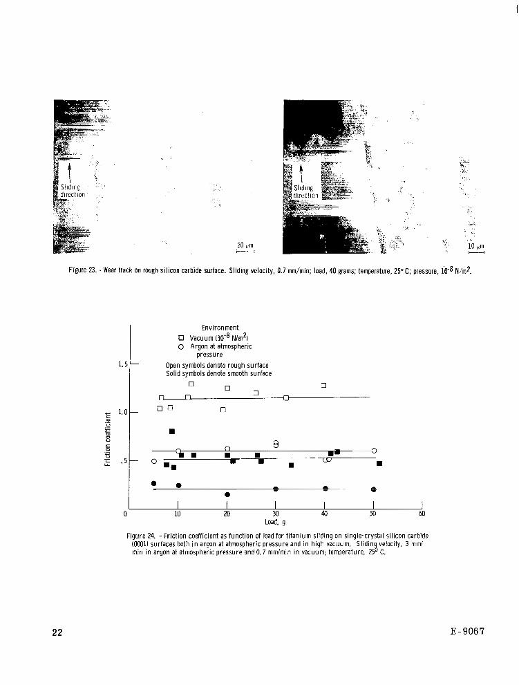
Wear of titanium sliding on rough silicon carbide. - With a rough surface, silicon carbide was transferred to the titanium and the silicon carbide fractured and plastically deformed. Figure 22 reveals the film of silicon carbide transferred to the titanium and a large number of deep grooves. These grooves are formed by the plowing of hard as- perit ies of silicon carbide (fig. 12(b)). Figure 23 contains scanning electron micrographs of the silicon carbide wear track. Fracture and plastic deformation have been generated with sliding. These facts suggest that the grooves are produced by plowing of hard sili- con carbide asperities transferred to the titanium. Furthermore, a t ransfer of titanium to silicon carbide was also confirmed.
Comparison of Results in Argon and Vacuum Environments
Figure 24 summarizes friction coefficients measured at various loads in both argon and high vacuum. The friction differences are significant. With a smooth surface of silicon carbide in argon both at atmospheric pressure and in high vacuum, adhesion plays an important role. With a rough surface of silicon carbide in both environments, friction is due to shearing adhesive bonds at the interface and cohesive bonds in titanium o r sili- con carbide and to plowing of the titanium by asperities of silicon carbide.
With a rough surface of silicon carbide in high vacuum, frictional energy may be also dissipated by the plastic deformation and fracture of silicon carbide (fig. 23).
6
The friction and wear data obtained with silicon carbide contacting titanium indicate that two wear mechanisms are involved when these materials are in sliding contact. Both adhesive and abrasive wear occur. In argon, with the lower surface contaminants, friction was greater for the rough surface than it was for the smooth surface. A differ- ence in friction between the smooth and rough surfaces persisted in vacuum, but the friction coefficients for both surfaces were considerably higher in vacuum than in argon. The increase in friction observed with both surfaces in vacuum, when the surfaces were clean, reflects the increase in interfacial adhesive bonding when surface contaminants are removed. Thus, adhesion contributes to friction and wear.
The fact that a difference in friction coefficient for the smooth and rough surfaces exists in both environments, with the smooth surface exhibiting the lower value, indicates that a force in addition to adhesion is contributing to friction. That force is the force necessary for the asper i t ies of the rough silicon carbide to plow through the titanium. It is the force that contributes to the generation of abrasive wear particles. Thus, the friction coefficients for the smooth surface in both environments reflect adhesion forces, while the difference in friction coefficient for the smooth and rough surfaces represents the effect of plowing or plastic deformation.
CONCLUSIONS
A s a result of sliding friction experiments conducted with single-crystal silicon car- bide in sliding contact with titanium, the following conclusions were drawn:
1. The friction coefficient in vacuum w a s greater than that in argon, and this was due to the greater adhesion o r adhesive transfer in vacuum.
2. Both in argon at atmospheric pressure and in high vacuum, thin f i lms of silicon carbide transferred to the titanium. Titanium also transferred to silicon carbide. The cohesive bonds on both the silicon carbide and titanium surfaces fractured as a result of sliding.
3. Silicon carbide wear debris caused by fracture plowed the silicon carbide surface
4. The friction characteristics of titanium in contact with silicon carbide were in a plastic manner.
sensitive to the surface roughness of silicon carbide. The friction coefficients were higher with a rough surface of silicon carbide than with a smooth one. The difference in friction results was due to plastic deformation (plowing of titanium).
Lewis Research Center, National Aeronautics and Space Administration,
Cleveland, Ohio, May 3, 1977, 506- 16.
7
RJ3FERJ3NCES
1. Brookes, C. A. ; and Imai, M. : The Frictional Properties of Silicon Nitride and Silicon Carbide. Special Ceramics 1964. P. Popper, ed., Academic Press, 1965, pp. 259-266.
2. Brookes, C. A. ; and Atkins, A. G . : The Friction and Hardness of Refractory Com- pounds. Fifth Plansee Siminar De Re Metallica on Metals for the Space Age. F. Benesovsky, ed., Metallwerk Plansee AG, 1965, pp. 712-720.
3. Adewoye, 0. 0. ; et al. : Structural Studies of Surface Deformation in MgO, S i c and Si3N4. Cambridge Univ., England (AD-A008993), 1974.
8
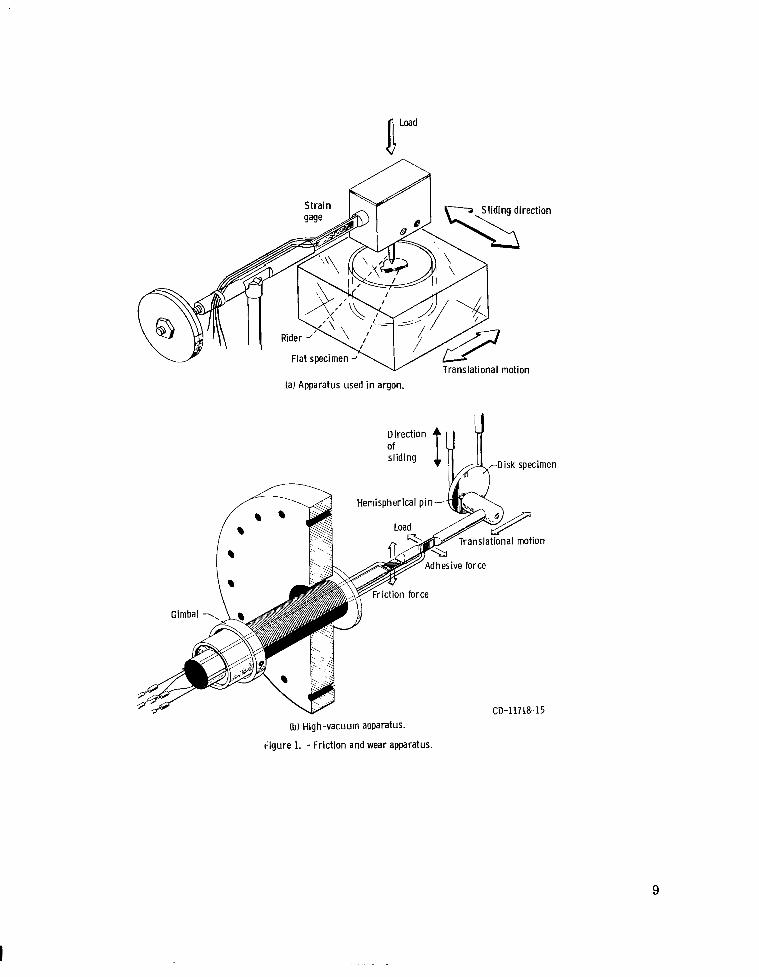
(a) Apparatus used in argon.
Hemispherical pin-
CD-11718-15
(b) High-vacuum apparatus.
r i gu re 1. -Frict ion and wear apparatus.
9
I
AO. 5 Prn
100 prn
.. . .
(b) Rough (as-grown) surface.
Figure 2. - Surface profile curves for silicon carbide.
Surface 0 Rough 0 Smooth
Figure 3. - Friction coefficient as function of load for t i tanium sl iding on single-crystal silicon carbide (ooO1) surfaces in argon at atmospheric pressure. Sliding velocity, 3 m m h i n ; temperature, BO C.
10
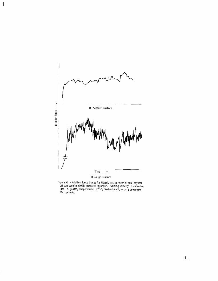
(a) Smooth surface.
I
Time - (b) Rough surface.
Figure 4. - Friction force traces for t itanium sliding on single-crystal silicon carbide (OOO1) surfaces in argon. Sliding velocity, 3 mmlmin; load, 20 grams; temperature, 25' C; environment, argon; pressure, atmospheric.
11
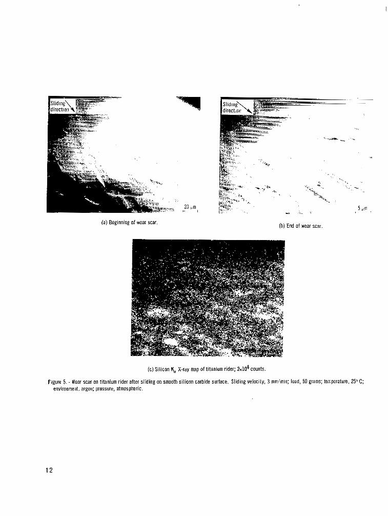
(a) Beginning of wear scar. (b) End of wear scar.
(c) Silicon K, X-ray map of titanium rider; &lo4 counts.
Figure 5. - Wear scar on titanium rider after sliding on smooth si l icon carbide surface. Sliding velocity, 3 mmhin; load, 50 grams; temperature, 25" C; environment, argon; pressure, atmospheric.
12
. . . .
(a) End of wear scar. (b) Beginning of wear scar.
Figure 6. - Beginning and end of wear scar on titanium rider after sliding on smooth silicon carbide surface. Sliding velocity, 3 mm/min; load, 50 grams; temperature, 25" C; environment, argon; pressure, atmospheric.
* Sliding 'a direction - p.
x
. _ .
Figure 7. - Adhesion of titanium to smooth silicon carbide surface. Sliding vzlocity, 3 rr;mhin; load, 50 grams; temperature, 25O C; environment, argon; pressure, atmospheric. (Fracture OCCUIS in silicon carbide.)
13
* ..
(a) Wear scar. (b) Titanium K, X-ray map of titanium rider; 4 ~ 1 0 ~ counts.
Figure 9. - Wear Scar on titanium rider after sliding on rough sil icon carbide surface. Sliding velocity, 3 mm/min; load, 30 grams; temperature, 25" c ; environment, argon; pressure, atmospheric.
14
I
y*
I"4
(a-1) Scanning electron micrograph. (b-1) Scanning electron micrograph.
(a-2) Titanium K, X-ray map of sillcon carbide surface; &lo3 counts.
(a) Contact asperities.
(b-2) Titanium K, X-ray map of silicon carbide surface; 5 ~ 1 0 ~ counts.
(b) Asperities capped with titanium.
Figure 10. ~ Adhesion of titanium to asperities on rough sil icon carbide surface. Sliding velocity, 3 mm/min; load, 30 grams; temperature, 25" C; environment, argon; pressure, atmospheric.
1 5
la) Before sputter cleaning of smooth surface.
~ . . " .
( c ) Before sputter cleaning of rough surface.
L . - .
(b) After sputter cleaning of smooth surface.
(d) After sputter cleaning of rough surface.
Figure 11. - Auger emission spectroscopy spectra for silicon carbide single-crystal surfaces.
L - - - Jo. 5 vm
100 pm - .. .
(a) Smooth surface.
(b) Rough surface.
Figure 12. - Surface profile curves for silicon carbide after sputter cleaning.
16
l.5/
Surface
Smooth 0 Rough
Y L
I 0
.= ==
I 10
I 20
I 30
I 40
1- 50 I
60 Load, g
Figure 13. -Frict ion coeff icient as func ion o load for t itanium sliding on single-crystal si l icon carbide (0M)l) surface in vacuum (10- Nlm ). Sllding velocity, 0.7 mmlmin; temperature, B h "
250 c.
t P I (a) Smooth surface.
I Time -
(b) Rough surface.
Figure 14. - Friction force traces for t itanium sliding on single-crystal si l icon carbide (ooO1) surfaces in vacuum. Sliding velocity, 0.7 mmlmin; load 40 grams; temperature, 25' C; pressure, lo-* Nlm'.
17
t-, ." 4
I ' e i "
. '
Q
p" :i ;I
"1
-
Figure 15. - Adhesion of t i tanium to smooth sil icon carbide surface. Sliding velocity, 0.7 mm/min; load, 40 grams; temperature, 25O C, pressure, 10-8 N/rn2.
Y
(a) Wear scar. (b) Silicon K, X-ray map of titanium rider; 5 ~ 1 0 ~ counts.
Figure 16. - Wear scar on titanium rider after sliding on smooth silicon carbide surface. Sliding velocity, 0.7 mm/min; load, 40 grams; temperature, 25°C; pressure, lo-* N/m2.
18
I
,Sliding : direction 2 / #
(a) Adhesion of titanium to silicon carbide. (b) Titanium K, X-ray map of si l icon carbide, flat specimen; &lo3 counts.
Figure 18. - Thin f i lm of titanium transferred to si l icon carbide. Sliding velocity, 0.7 mm/min; load, 40 grams; temperature, 25°C; pressure, lo-* N/m2.
19
I ".
I
t 2 ; 10
(a) Silicon carbide wear debris. (b) Titanium K, X-ray map of si l icon carbide, f lat specimen; 5 ~ 1 0 ~ counts.
Figure 19. - Silicon carbide wear debris capped with titanium. Sliding velocity, 0.7 mm/min; load, 40 grams; temperature, 25°C; pressure, N h 2 .
Sl iding direction
f
20 am H
20
I
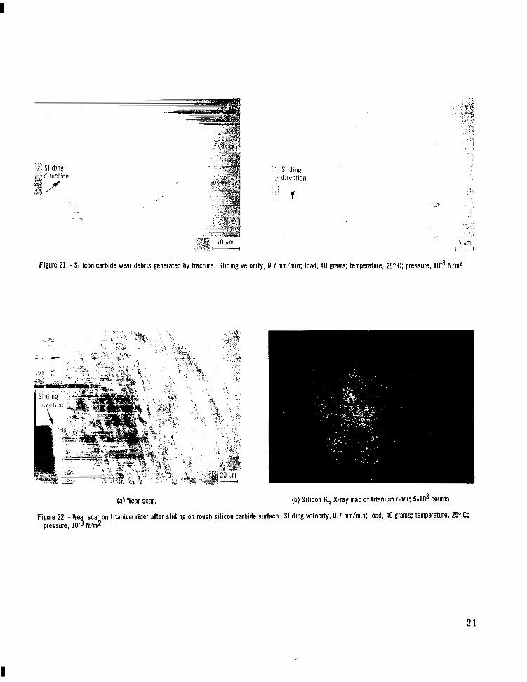
Figure 21. - Silicon carbide wear debris generated by fracture. Sliding velocity,
Sliding directlon
0.7 mm/min; load, 40 grams; temperature, 25" C ; pressure, N/m2.
(a) Wear scar. (b) Silicon K, X-ray map of titanium rider; &lo3 counts.
Figure 22. - Wear scar on titanium rider after sliding on rough sil icon carbide surface. Sliding velocity, 0.7 mmhin; load, 40 grams; temperature, 25" c; pressure, 10-8 N h 2 .
2 1
t" i 20
'. .
Figure 23. - Wear track on rough silicon carbide surface. Sliding velocity, 0.7 mm/min; load, 40 grams; temperature, 25" C; pressure, N h 2 .
1 .5
c 1.0 .- c al V
al 0 V
c 0
V
Y
.- c L
1-
c .- L .5
0
Environment 0 Vacuum N/m2) 0 Argon at atmospheric
Open symbols denote rough surface Solid symbols denote smooth surface
pressure -
0 0 -
0
10 20 30 40 M 60 Load, g
Figure 24. - Friction coefficient as function of load for titanium sliding on single-crystal silicon carbide 1ooO1) surfaces both in argon at atmospheric pressure and in h igh vacuum. Slidin velocity, 3 mml min in argon at atmospheric pressure and 0.7 mmlmin i n vacuum; temperature, 25 C. ?I
22 E- 906 7
1. Report No. I 2. Government Accession No.
NASA TP-1035 4. Title and Subtitle
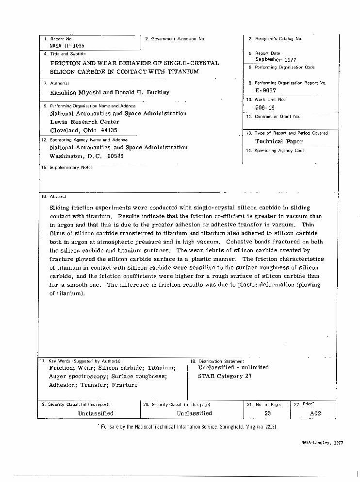
FRICTION AND WEAR BEHAVIOR OF SINGLE-CRYSTAL SILICON CARBIDE IN CONTACT WITH TITANIUM
7. Author(s)
Kazuhisa Miyoshi and Donald H. Buckley
9. Performing Organization Name and Address ~.
National Aeronautics and Space Administration Lewis Research Center Cleveland, Ohio 44135
12. Sponsoring Agency Name and Address
National Aeronautics and Space Administration Washington, D. C. 20546
15. Supplementary Notes ~.
3. Recipient's Catalog No
5. Report Date
September 1977 6. Performing Organization Code
8. Performing Organization Report No.
E- 906 7 10. Work Unit No.
506- 16 1 1 . Contract or Grant No
13. Type of Report and Period Covered
Technical Paper 14. Sponsoring Agency Code
16. Abstract _ ~ _ ~.
Sliding friction experiments were conducted with single-crystal silicon carbide in sliding contact with titanium. Results indicate that the friction coefficient is greater in vacuum than in argon and that this is due to the greater adhesion or adhesive transfer in vacuum. Thin films of silicon carbide transferred to titanium and titanium also adhered to silicon carbide both in argon at atmospheric pressure and in high vacuum. Cohesive bonds fractured on both the silicon carbide and titanium surfaces. The wear debris of silicon carbide created by fracture plowed the silicon carbide surface in a plastic manner. The friction characteristics of titanium in contact with silicon carbide were sensitive to the surface roughness of silicon carbide, and the friction coefficients were higher for a rough surface of silicon carbide than for a smooth one. The difference in friction results was due to plastic deformation (plowing of titanium).
17. Key Words (Suggested by Authorls))
Friction; Wear; Silicon carbide; Titanium; Auger spectroscopy; Surface roughness; Adhesion; Transfer; Fracture
18. Distribution Statement ~~~
Unclassified - unlimited STAR Category 27
I 19. Security Classif. (of this report) 20. Security Classif. (of this page) 21. No. of Pages 22. Price'
Unclassified Unclassified 1 A02 - =- I * For sale by the National Technical Information Service, Springfield. Vlrginla 22161
NASA-Langley, 1977
National Aeronautics and Space Administration
Washington, D.C. 20546 Official Business
Penalty for Private Use, $300
SPECIAL FOURTH CLASS MA1 L Postage and Fees Paid
Space Administration NASA451
BOOK National Aeronautics and
USMAIL
NASA
593 0 0 1 C 1 U C 770819 S00903DS DEPT OF THE AIR FORCE AF WEAPOMS L B E O R A ' T O R Y ATTN: T E C H N I C A L L I B R A R Y (SUL) K X R T L A N D A F B N M 87117
!
POSTMASTER: If Undeliverable (Section 158 Postal Manual) Do Not Return