Embed Size (px)
DESCRIPTION
Fried Model H kIt Assembly and Setup instructions
Citation preview
.... '- --,-,~~ " ~_.., ,- - - - - ~'",,i
"
VI,1"'FRIED Pro~ucts Co. 7616 City Line Avenue
Philadelphia,Pa. 19151Irhe FRIED Model "H" Kit:I Assembly and Setup hwtructions,
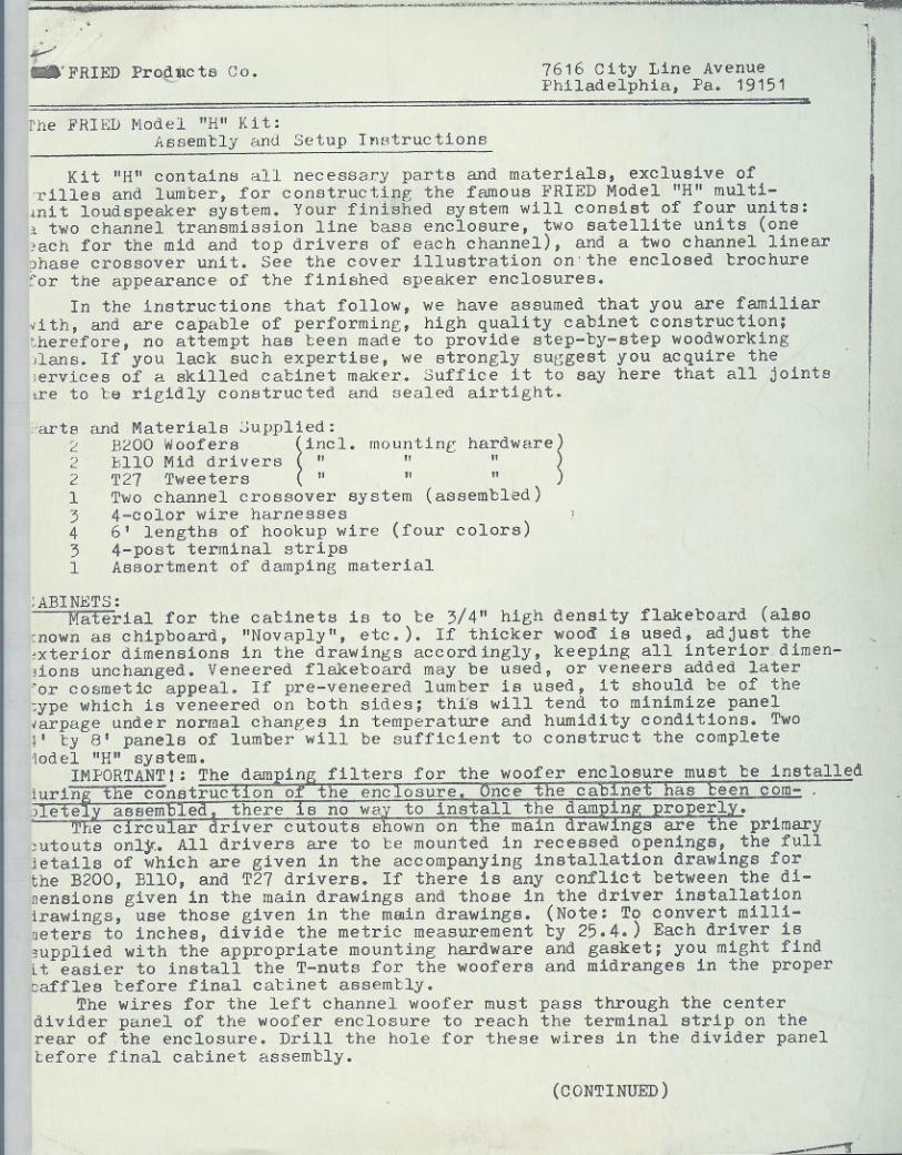
Ki t "H" contains all necessary parts and materials, exclusive ofI,rilles and lumber, for constructing the famous FRIED Model "H" multi-pnit loudspeaker system. Your finished system will consist of four units:j~ two channel transmission line bass enclosure, two satellite units (one[,:,achfor the mid and top drivers of each channel), and a two channel linear,~hase crossover unit. See the cover illustration on'the enclosed brochure!for the appearance of the finished speaker enclosures.
In the instructions that follow, we have assumed that you are familiarI,ith, and are capable of performing, high quality cabinet construction;1therefore, no attempt has been made to provide step-by-step woodworking)lans. If you lack such expertise, we strongly sUGgest you acquire theJervices of a skilled cabinet maker. Suffice it to say here that all jointsire to be rigidly constructed and sealed airtight.
karts2')L
213431
and Materials Supplied:B200 Woofers
~
incl. mountinr hardware
~
bllO Mid drivers" II "T27 Tweeters " " "Two channel crossover system (assembled)4-color wire harnesses6' lengths of hookup wire (four colors)4-post terminal stripsAssortment of damping material
:ABINETS:Material for the cabinets is to be 3/4" high density flakeboard (also
mown as chipboard, "Novaply", etc.). If thicker wood is used, adjust the,xterior dimensions in the drawings accordingly, keeping all interiordimen-3ions unchanged. Veneered flakeboard may be used, or veneers added later'or cosmetic appeal. If pre-veneered lumber is used, it should be of theI,ype which is veneered on both sides; thi's will tend to minimize panel,arpage under normal changes in temperature and humidity conditions. Two"' by 8' panels of lumber will be sufficient to construct the complete10del "H" system.
IMPORTANT I: The damping filters for the woofer enclosure must be installedlurin the construction of the enclosure Once the cabinet~een com- ,
J e e assem e there s no wa to install the am n ro erl .
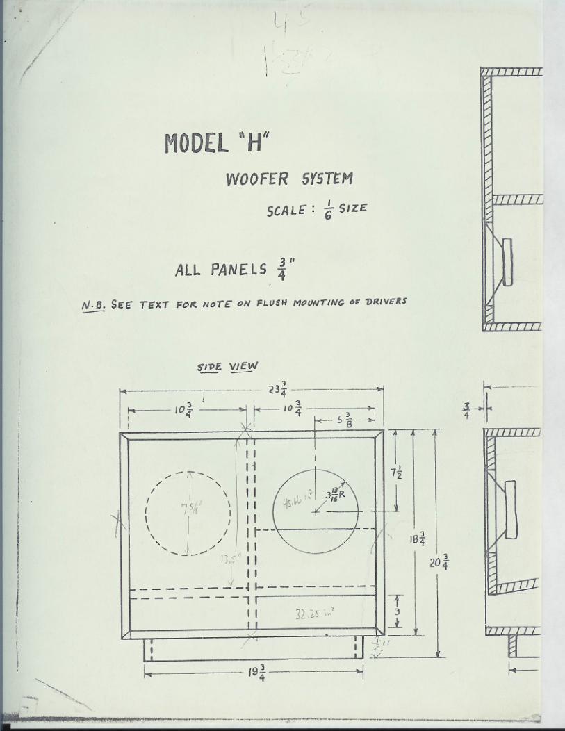
e c rcu ar river cu outs 8 own on e ma n raw ngs are e primary~utouts only. All drivers are to be mounted in recessed openings, the fullletails of which are given in the accompanying installation drawings for'theB200, BlIO, and T27 drivers. If there is any conflict between the di-nensions given in the main drawings and those in the driver installationlrawings, use those given in the mwin drawings. (Note: To convert milli-'aeters to inches, divide the metric measurement by 25.4.) Each driver is3upplied with the appropriate mounting hardware and gasket; you might findLt easier to install the T-nuts for the woofers and midranges in the properbaffles before final cabinet assembly.
~he wires for the left channel woofer must pass through the centerdivider panel of the woofer enclosure to reach the terminal strip on therear of the enclosure. Drill the hole for these wires in the divider panelbefore final catinet assembly.
"
(CONTINUED )
~
- -- -.
lFRIED Products Co. 7616 City Line Avenue
Philadelphia, Fa. 19151
FRIED Model "H" Kit -2-
WIRING:WOofer Enclosure:Four six-foot lengths of color coded wire are supplied in the kit.
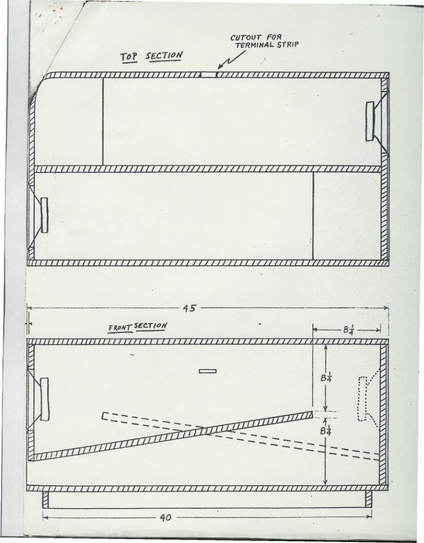
Use 4 feet of each wire for the woofer enclosure.Mount the terminal strip at the top rear of the cabinet; this will
allow the internal wiring to pass through only one internal panel betweenthe left channel woofer and the terminal strip. Since !'Iodel"R" uses atwo channel tass system, each woofer terminal must be connec.ted to a sep-arate post on the terminal strip. Therefore, the terminal strip posts mustbe marked: left plus, left minus, right plus, right minus.
The positive terminals on each woofer are marked in red; the negativeterminals are unmaxked. Using the wire supplied, connect each terminal onthe drivers to the correct terminal on the terminal strip, routing thewires for the left channel woofer through the center divider panel.
Seal all holes in panels through which the wiring passes, includingthe rear pane~lwhere the terminal strip is mounted.
Satellites:Use the remainder of the four color coded wires for the satellite
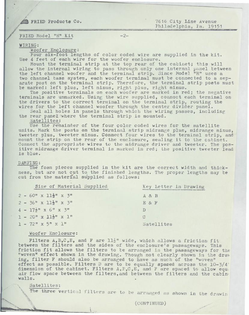
units. Mark the posts en the terminal strip midrange plus, midrange minus,tweeter plus, tweeter minus. Connect four wires to the terminal strip, andmount the strip on the rear of the enclosure, sealing it to the cabinet.Connect the appropriate wires to the m.idrange dr.iver and tweeter. The pos-itive midr81lge driver terminal is murked in red; the positive tweeter leadis blue.
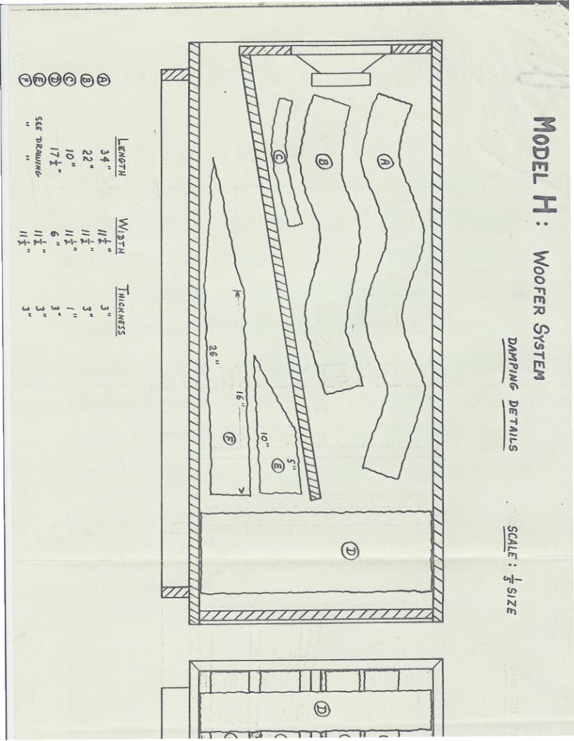
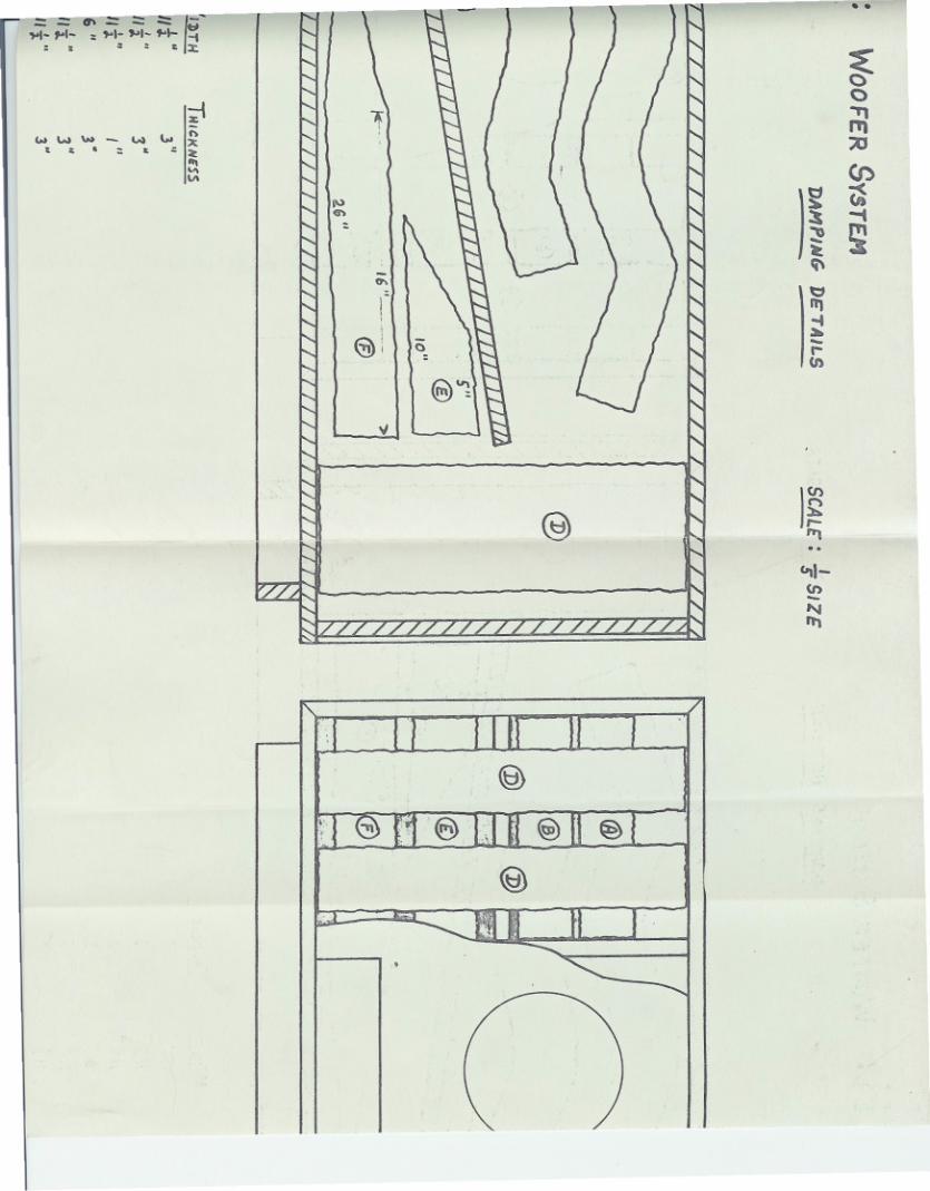
DAMPING:The foam pieces supplied in the kit are the correct width and thick-
ness, but are not C!lt to,the finished lengths. The proper lengths may becut from the matertal supplied as follows:
,Size of Material Supplied
2 - 60" x lIt" X 3"
2 - 36" X lIt" x 3"
4 - 17i" x 6" x 3"
1 - 20" x lIt" X I"
1 - 72" X 5" x 1"
Ke,y_l,ette.:_.i~Dra~_lng
A & BE & FDC
Satellites
Woofer Enclosure:
Filters A,B,C ,E, and Fare ll-!!"wide, which allows a friction fittetween the filters and the sides of the enclosure's passageways. Thisfriction fit allows the filters to be arranged i11 the passageways for the"woven" effect shown in the drawing. Though not clearly shown in the dra.ing, filter F should also be arrane;ed to have as much of the "woven"effect as possible. Filters D are to te equally sp~~d across the 10-3/4'dimension of the cabinet. Filters A,P,C,E, and F are spaced to allow equ,air flow space between the filtel's,and between the fi1tel's and the cabin.walls. .
- '\ Satelli tea:
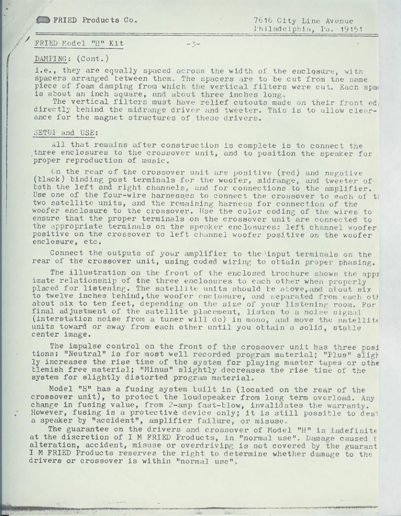
\\The three vertici)lfilters are to be arranged us shown in the dri'iwirl. (CONTINUED)
.\-
./
. - FRIED Products Co. 7610 City Line Avenuel'hiladelphia, I'a, 19151--- ,.,-
,/;'
/1/ FHllilll';odel "I!" Kit.-,,-
DAMI'ING: (Cant,)
1.e., they are equally spaced acro~;s the width of tho enclqslAre, v,lthspacers arra.."lged between them. 1'he spacers are to bo cut from the samepiece of foam damping from which the vertical filters were cut. Each spaeis about an inch square, and about three inches long.
The vertical filters must h8ve relief cutouts made on their front edldirectly 'behind the midranr:e driver and tweeter. This is to allow clear-ance for the magnet structures of thefJe drivers.
SET!)}' and USE:
All that remains after construction is complete is to connect thethree enclosures to the crossover unit, and to position the speaker for
'proper reprod uc tion of music,
Cn the rear of the crossover unit are positive (red) and nee:ative(tlack) binding post terminals for the woofer, midrange, and tweeter ofboth the left and right channels, and for connections to the amplifier.Use one of the four-wire harness,es to connect the crOlmover to euch of tJtwo satellite units, and the remaining harnens for connection of thewoofer enclosure to the crossover. Hse the color codinG of the wires toensure that the proper terminals on the crossover unit are connected tothe appropriate terminals on the spenker enc losuresg left channel wooferpositive on the crossover to left channel woofer posJtive on the wooferenclosure, etc.
Connec t the outputs of your amplifier to the 'input terminals on therear of the crossover unit, using coded wiring to obtain proper phasing.
The illustrationon the front of the enclosed brochure shows the appJimate relationship of the three enclosures to each other when properlypl~ed for listening. The satellite units should be "love,and B~out sixto twelve inches behind,the woof'er cncloCJure,and separated from each oUa'bout six to ten feet, depending on the size of your listenin/!room. Forfinal adjustmentof the satellite placement, listcn to a nOifJe01gn;11(interstation noise from a tuner will do) in mono, and move the sBtellitfuni ts toward or away from each other until you ottain a solid, statlecenter image.
The impulse control on the front of the crossover unit has three positions: "Neutral" is for most well recorded program material; "Plus" slilSfly increases the rise time of the system for playing master tapes or otheblemishfree materia.l;"Minus" slightly decreases the rise time of thesystem for slightlydistorted program material.
Model "H" has a fusing system built in (located on the rear of thecrossover unit), to protect the loudspeaker from long term overload. Anychange in fusing value, from 2-amp fas-t-'blow, invalidates the warranty.However, fusing is a protectiv~ device only; it is still possitle to desia speaker by "accident", amplifier failure, or misuse"
The guarantee on the drivers am! crossover of Model "H" is indefiniteat the discretion of I M FRIED Products, in "normal use"" Damage caused talteration, accident, misuse or overdrivipgis not covered by the guarantI M FRIED Products reserves the right to determine whether damage to thedrivers or crossover is within "normal use".
,""_<i.""';'
f. "."H',' :,. .",.'....~ ~" ., ,~. - ,
..;.;..,-
) I
II
r
I
MODEL"H" :
1< Bt~~ 4'~
"
I,
FRONt
,,~R
32n'R
,~
SATE"LLIT£ SYSTEM (2)>.
SCALE: f SIZE
N.8.S~f: n:xT FOR NoTE ON; FLVSU MOUNT/N6- OF 7a.IVERS
ALL PAWnS~ "
:< 6~ >1
A
I
-~1I I
I I i, I ,3.!. I 1
8 .
I
g'i- I8 '!I
iI Il 124
I
I
~fiVE: rECTttJlII
CUTOUT FoR
~TERMINAL. STRIP
".'"".","I"
""'.
.. K I r:u t-'KVUUGI;::O G V IVI t-'1-\ l'j Y
7616 C'tyLine Avenue. Philadelphia,Pa. 19151, 215-473.7474 - Sales
4041 Ridge Ave., Phila..Pa., 19129, 215-849-5136 - warehouse, service
.
/;
DAMPING FILTER LAYOUT FOR MODEL II SATELLITE AND MODEL M MID/TI'IEETER
ENCLOSURE (Cutaway view of Model H satellite with front, top, and oneside removed)
NOTE: All Model H, serial #]02(, dnd later, alld all Modeland later, have this damping factory-installed. '\'0units, fill in the dr iver clearance cutouts in theters (AJ, and add filter (n).
M, ser ia 1 !lO J 1().,
modify earliervertical fil-
{A)
(B)---
(NOTE TO KIT BUILDERS:addendum supplants thesattelite damping diagincluded in the ModelKit instructions.)
~{D)
A) Main vertical filters are 11" high, 5" deep, 1" thick. (In the Model Mthe front edge of this filter is angled to match the slant of the fronof the enclosure.)
B) Foam spacers are 1" square, and about 4" long (3 spacers per side).
c) Rear vertical filter is II" high, 1" t.hick, and wide enough to holdthe main filters (A) snugly aqainst the spacers (B).
DJ Bottom pad covers the bottom of the enclosure between the verticalfilters.
~
~---" '" . ""'"
.,
//
/
I . I,I!
I\I
MODEL"H"WOOFERSYSTtM
seA L£: ~ SIZ£
ALL PANELS ~"N.B. SE'~ TE"XT FCI/f. NoTE" ON FLUSI-/ MOUNT/Ne. OF 1>R.IVE'RS-
.1
I~
, "---. ~
.';:'" """'" "-
S"/T>f VieW--)
.- <34_~-_n_-' dl'°4-.
..I r-- £~ ~ IrrI
1104
II11- (
f-, II
/" '\ III {I \"
/ 75/g I II \
/
I
I 10--
t\ / I, '-- ./\ /I I ----------' "
"-J_-- 1].5°III II ----.J_~I-----
- - - -=- -, r--- "
"I J"R,~"/ii
4$,' -+.
--/
1U'S' ,"1
/ I I -?'I
k ~IS,!4
..., ,~ ,,-~._.------
J
T3
-1.
7i
3IB4'
I )
2°4
---
~
'111111
1\
1/
TT7
fr-.
T~
.d:.:J
..
rr
is "
.B ' I IFRt>NT~~C.T/ON ;r ~!
'-nT1111
I"- 8- ,.':/,,-
1
4 : :'" ... .. .. ,. ....,-- -- : ;..
J c -- - - - '/iJJJ---r- L~ \,/ - - - - - , I -f '* .-- -8-- ,.
--r --., If L-A- ---- - --- - -- --, - -' --
mrfl --~I:::L-
IlT II
I1~ 40 ~
~,, """4-
--. m'____--_.---,-
j-----. f'. .
/I CUTour FOR.
TeRMIHAL.STRIP -TDP SEC.T/tJN / '
-'/ - -I.
V ....
1-'"
V
II I // /- 1// / IIV
II 1// II IIIII I I '" /1' /1/1// rTT II 'II
L.
I, .
... ..---...---
e8~@)@)€)
'": c:
d/1>_-~-..aO
: ~ >+- :~ .'"
r'"IV ... ~""""'". -"",- :t:
I
~- - v'- - - tI'1'\- f"\- : ,.\- "'1- to\- ""'
:: ,: &:1;
~... IN "" - W "" ~
&&':&'~
~'"
~ -
,..'":
t-I
~i
..&
"f
'"
0
@)~v
-
......... - ~.
@
~ 1£'"..lotI-(/)-NIt'\
~,.....
30tj",r-
:t:. .
()..""':::0
CJ')
t:s -tq\
I
~~;i~ v; ~- ~~ -;:J.:.'Is
:: ::. :r.
~...w"" ""~""",. ...'"'"
- ...... ,
~
~I-<n-'"'"
IU....
~0"Tt"':itJC/)
)
~ ~:s -t~ ~~
I~
.
'"!I
~i 0
v
@) 1(1)~r-'"'..
@
~