Embed Size (px)
Citation preview

Pergamon
Int. J. Impact Engng, Vol. 17, pp. 431-442, 1995 Elsevier Science Ltd
Printed in Great Britain 0734-743X/95 $9.50+0.00
MULTIPLE-MESH BUMPERS: A FEASIBILITY STUDY
Friedrich HiSrz 1, Mark J. Cintala 1, Ronald P. Bernhard 2, and Thomas H. See 2
~NASA - Johnson Space Center, Houston, Texas, 77058 2Lockheed Engineering & Sciences Co., 2400 NASA Road 1, Houston, Texas, 77058
Summa~3~----Discontinuous targets (meshes and grids) offer significant mass savings, on geometric grounds, relative to the continuous materials that are typically employed in collisional bumper designs. Laboratory experiments were conducted to compare single aluminura and multiple-mesh systems to those composed of continuous membranes for the ability to disrupt, disperse, and decelerate soda-lime glass and aluminum projectiles at velocitie,; ranging from 1-6 km/s. Material thickness, mesh size and the number of bumper elements were systematically varied, resulting in specific areal masses of 0.016 to 1.6 g/cm 2 for the total bumper. Damage to individual target elements and to witness plates were used to characterize the performance of specific test articles.
NOTATION
Op T =
F~ --
S = L =
M =
m t =
m r =
m s =
m e =
m F =
m p =
Projectile Diameter Thickness of Target (foil thickness or wire diameter) Cumulative surface area of bumper destroyed (]~ of all holes) Sepm'ation distance between individual meshes Tot~tl length of entire mesh stack Mesh size (center-to-center distance of mesh wires) ToteL1 bumper mass lost (from weight measurements before and after experiment) TotaL1 mass of particulates physically recovered after an experiment (sum of m s + m e )
Spall mass recovered downrange Ejecta mass recovered uprange Specific areal mass of bumper (g/era 2) Projectile mass
~TRODUCTION
Substantial tec, hnology developments focus on the design of efficient passive, collisional bumpers that disrupt, decelerate and disperse hypervelocity impactors in such a fashion that damage to any flight system will not exceed some threshold value, or is prevented altogether. The major thrust of these developments aims at providing adequate protection with a minimum of total shield mass. Total mass of any collisional shield must be viewed as a direct penalty to a prospective payload mass with the effect that launch costs will increase, possibly substantially, for any operating payload in near-Earth orbit.
The principle focus behind the present work is to show that targets need not be laterally continuous to efficiently disrupt, disperse and decelerate any prospective impactors [e.g. , 1 2, 3, 4, and 5], and that multiple-mesh stacks are particularly well suited for this purpose. The Mesh Double Bumper (MDB) concept of Christiansen and coworkers [1, 2 and 5] utilizes a single mesh at the bumper's entry side, yet all ensuing bumper elements consist of continuous, sheet-like materials, including relatively massive
431
432 F. HOP, Z et al.
"rear walls", which result in totally opaque shields. In contrast, most of the present targets are entirely manufactured from meshes. Consequently, they are (modestly) optically and mechanically transparent and will permit some debris to emanate to the rear for possible interaction with diverse flight systems. Sufficiently fine-grained, low-velocity debris may be tolerated by a fair number of flight systems. However, the use of a solid rear wall behind a mesh bumper is not precluded in order to render a completely opaque shield, if such a degree of protection is required [ I ].
The objective of this report is to evaluate the general utility of discontinuous bumpers materials by summarizing and comparing the results of three independent investigations on the penetration behavior of single, continuous aluminum targets [6], of single meshes [3] and of multiple-mesh stacks [4]. A few new experiments which employed thin rear walls, akin to those used by Christiansen [1], are described as well and offer direct comparison with other light-weight bumper designs.
EXPERIMENTAL CONDITIONS AND CRITERIA FOR EVALUATING BUMPER PERFORMANCE
Detailed initial experiment conditions and all post-mortem measurements are presented in H6rz et al. [3, 4 and 6] along with extensive photodocumentation on an experiment by experiment basis. The majority of experiments were conducted with soda-lime glass spheres (-3.2 mm in diameter; Dp) launched in a powder-propellant gun (< 3 km/s) or a small caliber light-gas gun (3-6 km/s). Other than projectile velocity, the major experimental variables included the separation distance between individual bumper elements (S = 1-10 cm), mesh-size (0.5 and 1.0 Dp), thickness of mesh wires (Dp/T = 2-10), specific areal bumper mass (mF = 0.016 - 1.6 g/cm2), and the absolute number of mesh layers within a given stack (n = 1-10). Most multiple-mesh targets were composed of identical meshes, yet a few experiments employed a mixture of different mesh types. The targets resided inside a plastic box (see Figure 1) such that dislodged material could be recovered after every test. The standard setup included an aluminum 1100 witness plate which had been blued with a water-based layout ink and which was placed at the rear wall of the target box (see Figure 1) at a known standoff distance (L).
Quantitative criteria to evaluate general bumper performance are not readily obtained at present, unless collisional shields employing thin rear walls are addressed [e.g., 1, 5 and 7]. We judged the use of such specific and relatively thin rear walls impractical and overly restrictive for our parametric studies, because such walls would have been completely destroyed during a fair number of experiments. Instead, we employed massive witness plates (T = 3 or 6 mm) to the rear of our target stacks to assure an internally consistent record of cratering, erosion and deposition at all conditions simulated. However, it is the witness-plate evidence that is not readily quantified, because the debris clouds and associated witness- plate patterns are very complex, geometrically [e.g., 6, 7, 8, 9, 10, 11, and 12]. While quantitative data are not readily extracted from such witness plates, even a cursory inspection with the unaided eye reveals subtle changes in the size frequency of debris particles and their geometric dispersion. Because of space limitations only a few witness plates are illustrated in this report and interested readers are referred to HOrz et al. [3, 4 and 6] for detailed photographic documentation of all experiments.
Criteria related to the displaced mass were also utilized in evaluating bumper performance by calculating the total mass lost (mE) for all target arrangements from weight measurements taken before and after an experiment, while the total mass recovered (mr) represents particulates physically collected from inside the target container. The sum of m t and projectile mass (mp) characterizes the maximum mass possibly contained within any debris cloud, yet we note that only an unknown fraction of this mass may actually reach a flight-system; in the ideal case of a perfectly opaque shield, this debris fraction will be 0. In such an ideal case, mt only represents a measure of the degree of internal damage that was suffered by the bumper itself during any specific event. On the other hand, mr is a measure of the bumper's tendency to shed materials that may physically damage neighboring flight systems, or -- at best -- that will escape into space to contribute to the growing population and long-term threats of orbital debris. Obviously, compared to the witness-plate evidence, these mass considerations are of minor significance when evaluating total bumper performance. Nevertheless, for otherwise equivalent bumpers, one would select that design which exhibits the least mass loss and that sheds the least number of particles.
The diameters of all penetration holes in a given target stack were measured in order to calculate their cumulative surface area (Fc), which represents a measure of the bumper's internal damage and, thereby, how much energy was dissipated. In addition, such surface area determinations may be used to evaluate the fractional surface area of a bumper system that is being destroyed during a specific event and/or
Multiple-mesh bumpers: a feasibility study 433
Figure 1. Target container made of aluminum and plexiglas. Custom-made meshes were fabricated out of aluminum welding rods that were inserted into pre-drilled holes and held in place by set screws. For most experiments the :separation plate/target holder was located midway within the box, such that the uprange and downrange compartment were separated permitting the distinction between ejecta- and spall-generated materials. The overall target container was 55 cm long and measured 30 cm square on the inside.
during any given period of time. A bumper that exhibits the smallest amount of internal damage would be the preferred choice among competing bumper designs of otherwise identical performance.
PENETRATIONS OF SINGLE PLATES AND MESHES OF EQUIVALENT THICKNESS
Experiments utilizing single, continuous aluminum membranes [6] and meshes of highly variable thickness [3] were conducted to explore the roles of target thickness (7) and of the specific areal mass of a bumper (mF; g/cm 2) in the collisional disruption of soda-lime glass projectiles. Significantly, the spatial distribution of the debris cloud varied substantially between continuous membranes and discontinuous meshes as illustrated in Figure 2, which shows representative experiments at various impact velocities and relative T of 0.5 and 0.1 Dp. A fairly centro-symmetric distribution of the debris clouds and witness-plate spray patterns resulted from experiments which employed the continuous membrane, as reported by others [e.g., 1 l, 12, 9, l0 and 13]. The absolute dispersion angle of the debris cloud sensitively depends on T [6 and 9]. Oblique impacts with continuous targets are characterized by debris clouds that have prominent bilate, ral symmetry [8].
As illustrated in Figure 2, the debris clouds emanating from a single mesh are highly irregular compared to the symmetrical spray patterns produced by continuous targets. The mesh size for these discontinuous targets was M = 0.5 Dp at 2.3 km/s and M = 1.0 Dp for the 5 and 6 km/s tests. Clearly, the witness-plate spray patterns mimic the mass distribution of the specific impact point in a mesh target.

434 F. HORZ et al.
Individual wires that were cut result in substantially linear sprays on the witness plate (e.g., see witness plate 803 in Figure 2). Such pronounced clustering of secondary impacts is undesirable for any collisional bumper, because it locally concentrates high specific kinetic energies (ergs/cm 2) on a flight system or a bumper's rear wall.
The largest witness-plate crater was of substantial interest, because it is a measure of the most energetic debris fragment, which is either produced from the target (typically at Dp/T < 2), or from the projectile when very thin foils (typically Dp/T > 10) are encountered [6]. Witness-plate observations revealed that there was no single, outstandingly large and energetic fragment in any of the experiments, but instead a small number (typically 10 to 20) of fragments of comparable size (at least for soda-lime glass impactors of 0.5 > Dp/T < 100). Without question, the largest craters are the result of dislodged target debris at massive T, and represent projectile fragments for thin T, as detailed by H6rz et al. [6]. For
C o n t i n u o u s D i s c o n t i n u o u s
Dp/'l" 2 10 2 10
2.3 km/s (1/4")
5 km/s 0/8")
6 km/s !1/8")
Figure 2. Spray patterns on witness plates associated with single continuous and discontinuous bumper experiments conducted at different velocities and Dp/T = 2 and 10. The circular footprint of the debris pattern resulted from the use of cylindrical witness plates which inhibited the radial dispersion of some of the debris. All witness plates were 29 cm square. Note that the continuous bumpers resulted in substantially more symmetrical spray patterns versus the irregular patterns associated with the discontinuous bumpers.
targets of Dp/T > 10, the number and size of projectile fragments remain relatively constant with decreasing T, yet their dispersion angle varies greatly [6]. While the largest witness-plate craters strongly depend on a large number of initial conditions, most notably T and the projectile velocity, we do not observe systematic differences between continuous or discontinuous targets at a given Dp/T, at least for glass impactors and scaled thicknesses of 2 > Dp/T < 100. This is a significant and important result, as it corroborates our basic premise that collisional bumpers need not be continuous.
As previously mentioned, all targets were weighed before and after an experiment in order to characterize the total mass loss (mr) of the bumper. Clearly, small amounts of displaced masses are desirable so as to minimize collisional interaction(s) with any flight system, and to inhibit the growth of debris in near-Earth space. Figure 3 illustrates our findings, with mt normalized to mp. Substantially less mass is displaced by the mesh experiments compared to foils for any given Dp/T condition. In general, mt sensitively depends on the cumulative bumper mass (mF), regardless of the detailed bumper design. This correlation substantiates that most debris is liberated from the bumper itself. Note that our mesh bumpers typically have an m F < 0.5 g/cm 2, because most meshes possess a Dp/T > 2. Since the

Multiple-mesh bumpers: a feasibility study 435
areal mass of t]he soda-lime glass projectiles is -0.46 g/cm 2, our mesh bumpers are extremely light weight. The relatively light-weight nature of these targets is also the reason why m t seems relatively insensitive to impact velocity in Figure 3.
For these single-component bumpers experiments, the target-holder plate was mounted at the mid- point (front to rear) of the target container (see Figure 1); the plate was sealed against the plexiglas walls to generate an uprange and downrange compartment to permit the distinction and collection of "ejecta" and "spall debrJis", respectively. The purpose was to physically characterize the masses and sizes of dislodged materials. Unfortunately, these particulates were somewhat contaminated by shredded and crumbled flakes from thin aluminum foils that were used as cylindrical witness plates in these experiments (see [3]). However, because all witness-plate materials were blued with a water-based lay- out ink, we could recognize many, but not all of the cylindrical witness-plate materials within the recovered debri,;. As a result of this contamination, precise mass determinations for materials dislodged from the bumpers were not possible. Nevertheless, the actual measurements suggest that fewer particulates are produced by mesh bumpers compared to continuous sheets of equivalent T. Unquestionably, downrange debris outweighs the uprange ejecta, typically by factors of 2-5, and by as much as an order of magnitude in these experiments [3]. Such ratios strongly depend on Dp/T.
10
l
0.1
0.01 0.01
! (A) V < 2 . 5 k m / s - n
Foil Grid Dp/ T •
• 2 a
• 4 & 5 o
• 8 & 1 0 ~ *
• 1 2 v
.-- ~ o
A
,~ , , I , , ~ , 1 , , , I . . . .
0. !
tl
.t ~ o w
o
D
! (B) V > 5 k m / s . !
• o
: ~ !
O
Foil Grid Dp/ T
• 2 []
• 4 & 5 o
• 8 & 1 0
• 1 2 v
o •
, , , I . . . . I , , , I . . . .
0 . 0 1 0 . I 1
Areal Shield Mass (mF ;g/cm 2) F i g u r e 3. Total mass loss (mt) normalized to projectile mass (rap; 0.037 g) plotted as a function of areal shield mass (mF). Note that mF (mp/It r 2) of the soda-lime glass projectile was 0.46 g/cm 2. In addition, note that the difference between the low- and high-velocities experiments is not dramatic for these rather thin and light-weight targets.
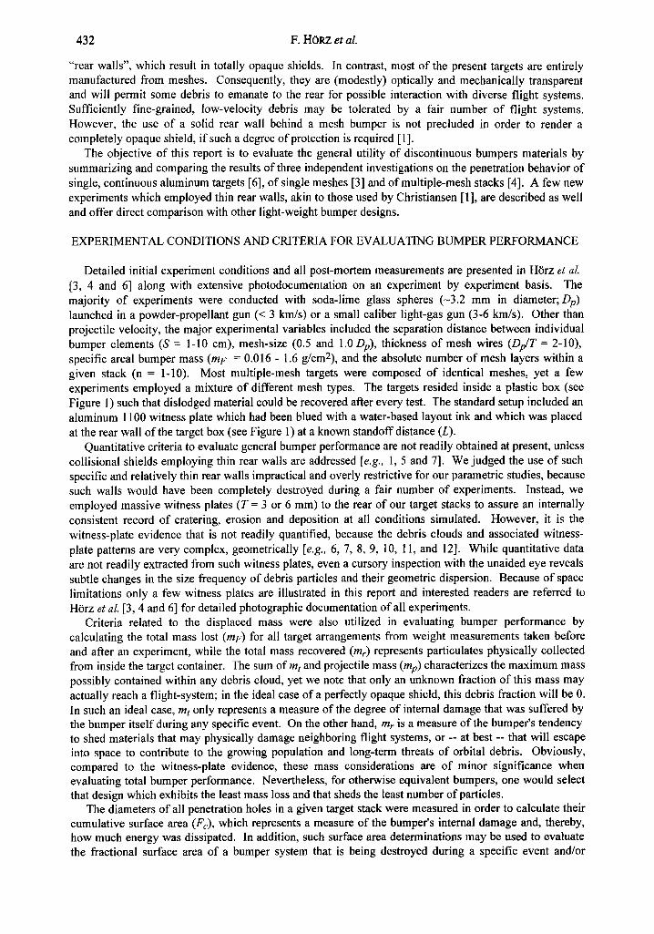
Following an experiment we sorted through the recovered particulates under a binocular microscope and handpicked the largest, non-blued fragment (i.e., most likely derived from the target); in the case of mesh targets Of Dp/T> 4, the largest fragment was always a piece of wire, while for the D y T = 2 case no demonstrable wire fragments were identified. The uprange debris was examined for the largest fragment as well. The mass of the largest uprange and downrange fragments normalized to mp are plotted as a function of mF in Figure 4. Examination of Figure 4 reveals that the data exhibit a large degree of scatter, yet we conclude', that continuous and discontinuous bumpers do not seem to differ systematically in the size of the large~;t debris fragment that they generate.
Summarizing the comparison of continuous and discontinuous bumper components, we conclude that T is the dominating factor in controlling the comminution, dispersion and the amount (i.e., mass) of displaced debris. There is no evidence from either witness-plate investigations or mass measurements on recovered particulates that continuous and discontinuous bumpers result in a systematically different size distributions of fragmentation products at equivalent Dp/T. As a consequence, meshes become very attractive bumper components, because they offer substantial mass-savings over continuous targets at any given Dp/T.
436 F. H(gRZ et al.
1.O
0,1
~ O.Ol
L (A) Largest Recovered Up-range Fragment
• Foil < 2.5 km/s ~ i Grid < 2.5 km/s Foil > 5 km/s
o Grid> 5 km/s
° i ¢
- o , , | o m 0~ o o • o
o o o
o • " D
L (B) Largest Recovered Down-range Fragment .-: O •
o [:3
o @ • - • •
l • o | o • . ° •
o o
o o • o •
o o;
N
0.001 L • Foil < 2.5 km/s L l -= Grid < 2.5 km/s
• • • "2 Foil > 5 km/s Grid> 5 km/s
0.0001 I , , I , , , , I I , , I , , , , , , I . . . . I ° l I , I , , i
0.01 0.1 1.0 0.01 0.1 1.0
Areal Shield Mass (mF;g/cm z) Figure 4. Mass of the largest fragments (normalized to mp) that were recovered from the uprange and downrange compartments of the target box (see Figure 1). Each data point represents an individual experiment.
PENETRATIONS OF MULTIPLE MESH TARGETS
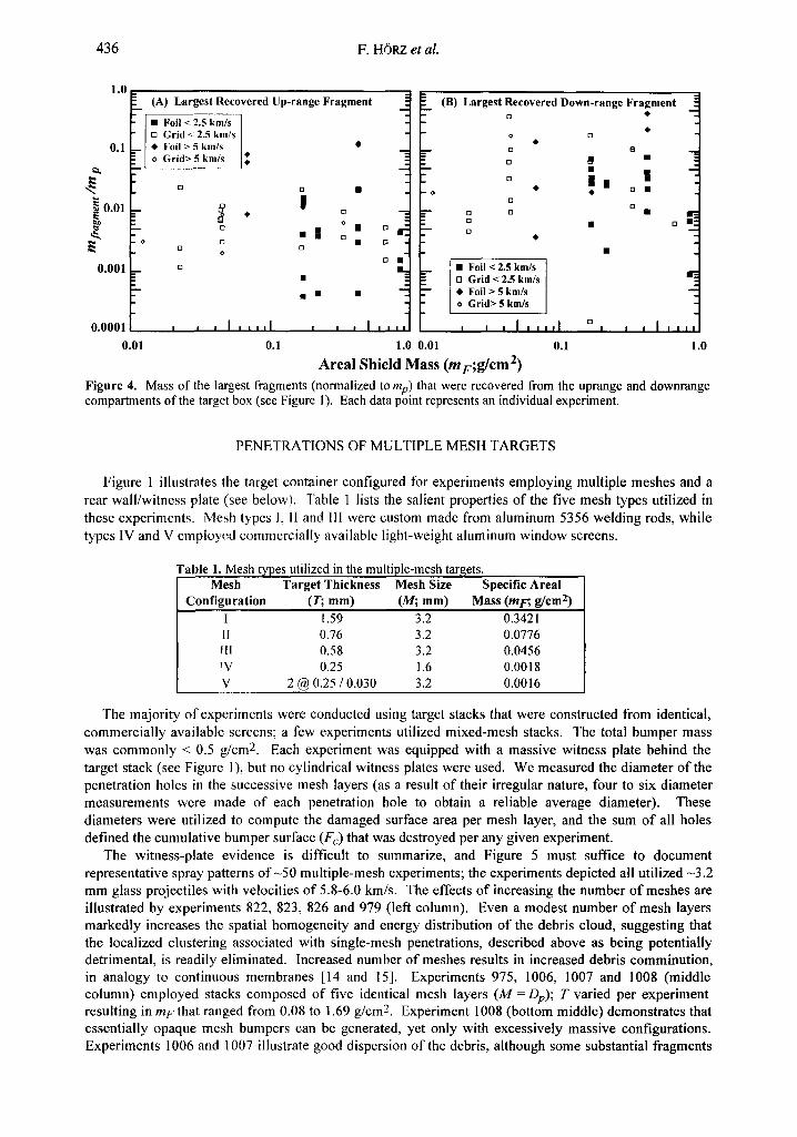
Figure 1 illustrates the target container configured for experiments employing multiple meshes and a rear wall/witness plate (see below). Table 1 lists the salient properties of the five mesh types utilized in these experiments. Mesh types 1, lI and IIl were custom made from aluminum 5356 welding rods, while types IV and V employed commercially available light-weight aluminum window screens.
Table 1. Mesh types utilized in the multiple-mesh targets. Mesh Target Thickness Mesh Size Specific Areal
Configuration (T; ram) (M; ram) Mass (mF; g/era z) 1 1.59 3.2 0.3421 II 0.76 3.2 0.0776 Fll 0.58 3.2 0.0456 rV 0.25 1.6 0.0018 V 2 @ 0.25 / 0.030 3.2 0.0016
The majority of experiments were conducted using target stacks that were constructed from identical, commercially available screens; a few experiments utilized mixed-mesh stacks. The total bumper mass was commonly < 0.5 g/cm 2. Each experiment was equipped with a massive witness plate behind the target stack (see Figure 1), but no cylindrical witness plates were used. We measured the diameter of the penetration holes in the successive mesh layers (as a result of their irregular nature, four to six diameter measurements were made of each penetration hole to obtain a reliable average diameter). These diameters were utilized to compute the damaged surface area per mesh layer, and the sum of all holes defined the cumulative bumper surface (Fc) that was destroyed per any given experiment.
The witness-plate evidence is difficult to summarize, and Figure 5 must suffice to document representative spray patterns o f -50 multiple-mesh experiments; the experiments depicted all utilized -3.2 mm glass projectiles with velocities of 5.8-6.0 km/s. The effects of increasing the number of meshes are illustrated by experiments 822, 823, 826 and 979 (left column). Even a modest number of mesh layers markedly increases the spatial homogeneity and energy distribution of the debris cloud, suggesting that the localized clustering associated with single-mesh penetrations, described above as being potentially detrimental, is readily eliminated. Increased number of meshes results in increased debris comminution, in analogy to continuous membranes [14 and 15]. Experiments 975, 1006, 1007 and 1008 (middle column) employed stacks composed of five identical mesh layers (M =Dp); T varied per experiment resulting in m F that ranged from 0.08 to 1.69 g/cm 2. Experiment 1008 (bottom middle) demonstrates that essentially opaque mesh bumpers can be generated, yet only with excessively massive configurations. Experiments 1006 and 1007 illustrate good dispersion of the debris, although some substantial fragments
Multiple-mesh bumpers: a feasibility study 437
do impinge upon the witness plate. In general, the majority of all coarse-grained debris exiting multiple- mesh stacks is de, rived from the meshes themselves. The right column in Figure 5 portrays the effects of separation distance, which ranged from 12.5 mm (experiment 989) to 101 mm (experiment 996). Fine-
Figure 5. Representative witness plates for experiments employing multiple-mesh stacks. All experiments used -3.2 mm soda-lime glass projectiles at impact velocities between 5.5 and 6.0 km/s. Witness plates are all 30 cm square. The number in the upper left-hand comer of each witness plate gives the experiment number, while the number in the upper right-hand comer is the separation distance (S) in centimeters. The number of mesh layers within an indiviclual experiment is listed in the lower left-hand comer of each witness plate, while the number in the lower right-hand comer is the areal mass (mF; g/cm2). Left-most column shows the effects of the number of mesh layers (2, 3, 5 a~d 10; top to bottom); single-mesh experiment (813) is illustrated in Figure 2. Middle column shows the effects of wire thickness (T) and associated m F for five-mesh experiments. Right-most column illustrates the effects of S for fen-member mesh stacks, except for experiment 996 that could only accommodate five mesh layers within the length of the target container because of the large S.

438 F. HORZ et al.
grained debris was generated in all of these tests, and debris size decreased noticeably with increasing separation distance, while the overall geometric dispersion increased and energy distribution became more homogeneous. Note that ten-mesh stacks with an L of 51 cm (~160 Dp) resulted in an almost opaque shield. Also note that the target box could only accommodate five meshes for experiment 996, which is half of the bumper mass relative to experiments 989, 982 and 996. Therefore, S is a crucial parameter and may result in substantial mass savings if it is maximized for every single flight application.
Akin to Figure 3, Figure 6a presents the total mass loss (mr) for multiple-mesh targets. Not surprisingly, the low-velocity experiments produce less m t than do the high-velocity penetrations, and low m F values result in relatively small m t as well, consistent with the penetrations of single targets. Note that the total projectile mass is 0.037 g. Consequently, the mass loss of the bumper system is frequently an order of magnitude larger than the incoming projectile mass. Figure 6b illustrates the total mass recovered (mr) from the target container, and shows the same trends as Figure 6a with many targets liberating multiple projectile masses. In detail, the particulates recovered in the downrange volume typically constitute > 70% of the total recovered mass.
" ' " ~/e/1/2 " 1 .~ ,9 ~ ° " " ' " ~/e///2 " ~ g g s , " -
Figure 6. (A) Total mass-loss (mt) of bumpers and (B) total mass of recovered particulates (mr) as a function of impact velocity and specific areal bumper mass (mF).
Considering the substantial degree of comminution, dispersion and deceleration of the projectile, as judged from the generally modest damage on the witness plates, the total mass displaced by these mesh targets seems modest in comparison to a single, continuous bumper. The latter, when close to the ballistic-limit thickness, will typically eject a complete crater volume (>10 mp) uprange, and downrange spall mass is commonly mt> 50 mp (see Figure 15 in [6]).
Examples of the types of damage sustained by successive mesh layers in a typical stack are illustrated in Figure 7. Note that mF of the individual meshes employed in experiments 979 and 982 are nearly identical (i.e., 0.016 versus 0.018 g/cm2), and that the differences in internal bumper damage are predominantly the result of M(i.e., 1.0 Dp and 0.5 Dp, respectively). Additionally, Figure 7 illustrates the effects of S (i.e., 2.5, 10.1 and 1.25 cm, respectively) using identical meshes in experiments 982, 996 and 989. Each of these experiments shows a gradual increase in the hole diameter in successive mesh layers until some maximum diameter is reached. Subsequently, the hole diameter rapidly decreases to zero over a comparatively small number of mesh layers. Both the increase and decrease in the hole size represent discrete step-functions, rather than a single uniform, dispersion angle. (see Figure 14 in [4]). Obviously, the periphery of the debris clouds is occupied by low-energy debris that is being progressively stripped from the cloud by successive mesh collisions. Conversely, the cloud center contains the most energetic fragments.
To gain some measure of the total internal damage suffered by the entire bumper we measured the diameter of each hole and calculated the cumulative mesh surface area (Fc) that was destroyed (Figure 8). Not surprisingly, the low-velocity impacts destroyed less surface area than the high-velocity collisions, and small mE values yield relatively large Fc. This suggests that significant amounts of mass are
Multiple-mesh bumpers: a feasibility study 439
A A A
~ ~i ~i ~
i il ̧ !!iiii ii! !
i i
Figure 7. Typica.l damage to successive layers within a mesh stack. The effects of mesh size (34) are addressed with experiments 979 and 982, while the effects of separation distance (S) are shown by experiments 892, 996 and 989. Note that it takes the penetration of more layers to maximize the penetration-hole size than it does to completely terminate the debris cloud by subsequent mesh layers. Also note that the penetration holes in successive layers are irregular in shape.. (i.e., debris cloud possesses different geometry from one layer to another due to mesh-debris; see experiment 982 meshes 3, 4, 5 and 6).
displaced from massive targets, and that most bumper damage results from debris dislodged from the bumper itself.
COMPARISON WITH OTHER LIGHT-WEIGHT BUMPERS
The objective of the present study was to range through a large number of variables and to identify those that seem to be the most significant for bumpers composed entirely of discontinuous meshes. The total number of mesh components, separation distances (S) and total stack depths (L) were not constrained by equivalent parameters employed in other light-weight bumpers. For instance, fewer continuous bumper elemerLts are typically utilized by Cour-Palais and Crews [14] or Cour-Palais et al., [16];
440 F. HORZ et al.
Christiansen and Kerr [5] employed a single mesh combined with a variety of continuous bumper elements. These bumper developments typically limit L to 10 cm, a substantial difference to the above experiments where L >> 10 cm. In addition, these other experiments typically employed aluminum projectiles and a relatively massive rear wall resulting in completely opaque shields. Due to these experimental differences, comparison with the present mesh bumpers is not readily made. Therefore, we conducted a few analog experiments with ~3.2 mm diameter aluminum impactors, thin continuous rear walls (T 0.5 mm), stack lengths (L of 10.5 to 14 cm), and most importantly a similar areal bumper mass (mF of < 0.4 g/cm 2) [1].
I000
100 . . . . .
]I: ] ! -L -]: _~##!~o
Figure 8. Cumulative surface area (Fc) of destroyed mesh.
Within the scope of this effort, only six analog experiments were conducted. Two experiments, illustrated in Figure 9, were successful in the sense that absolutely no penetration of the rear wall occurred. Experiment 1127 employed 13 mesh layers (0.237 g/cm 2) and a 6061-T6 aluminum rear wall of T = 0.38 mm, resulting in an mF of 0.34 g/cm2; L was 11.1 cm, and a 2024 aluminum projectile impacted at 5.86 km/s. The rear wall was not penetrated, yet modest bulging, erosion and deposition of molten aluminum did occur. Experiment 1122 used 10 meshes (0.18 g/cm 2) with anL = 14.3 cm, and a 0.51 mm thick rear wall (aluminum 2024; 0.135 g/cm2), yielding an mE of 0.317g/cm2; the impact velocity was 5.94 km/s. Again, the rear wall was not penetrated, but radial gauging and erosion of the rear-wall was prominent. Another ten-mesh experiment (1121) with an mF of 0.29 g/cm 2 and an L of 14.3, showed a single penetration (<< 1 mm in size) of the aluminum 6061 T6 rear wall (T = 0.46 mm). Experiment 1123 (nine-mesh stack; L = 11.1 cm; mF = 0.30 g/cm 2) exhibited a number of penetrations > 1 mm in size of the rear wall. The remaining two experiments utilized very thin rear walls (T = 0.05 mm and 0.025 mm) and up to 16 mesh layers, yet none of the thin walls tolerated the debris as both were penetrated by numerous fragments.
In summary, we observe that relatively simple screen materials made from aluminum wires can yield bumpers and total shields of mass properties that compare favorably with those of other, currently leading bumper designs (mE = 0.3-0.4 g/cm2). Significantly, substantial mass savings of the latter designs originated from the utilization of modem materials of favorable mechanical and thermal properties, such as Nextel, a fine-woven, dense, ceramic fabric [e.g., 1 and 16]. Open meshes made from such superior materials may offer additional mass savings. Also, the tightly woven Nextel fabrics are made from stranded twine; as a consequence, the fragment size of materials dislodged from the bumper itself will be much smaller than that from solid monofilaments of comparable thickness or mass, as already noted by Christiansen and Kerr [5]. Obviously, meshes made from materials superior to the present aluminum screens can readily be envisioned and additional mass savings relative to current light-weight bumper designs seem possible.
ALUMINUM VERSUS SILICATE PROJECTILES
Experiment 993 in Figure 9 shows the penetration path of an aluminum impactor through a ten-mesh stack (L = 25 cm; S = 2.5 cm). Note the effect of S in comparison to experiments 1122 and 1127. The relatively massive witness plate of experiment 993 does not show any substantial secondary craters, but is dominated by thin deposits of either aluminum melt or vapor; such deposits would readily be tolerated by rear walls o f T - 0.5 mm. Significantly, experiment 993 is the equivalent of 982 in Figures 5 and 7, and illustrates the subtle differences in the penetration and collisional-fragmentation behavior of aluminum and glass projectiles. The aluminum projectiles penetrate less (e.g., meshes 6, 7 and 8), and are more abruptly terminated than the silicate impactors. Multiple-mesh penetrations by aluminum projectiles at -6

Multiple-mesh bumpers: a feasibility study 441
#1127
in
: El ~i~ ~ I
13 [ ]
#1122
#993
Figure 9. Mesh-bumper experiments that employed -3.2 mm diameter aluminum (2024) impactors traveling at -6 km/s. To facilitate comparison with other bumper developments these experiments incorporated thin rear walls which increased the mF of the overall target to 0.31 g/cm 2 (experiment 1127) and 0.34 g/cm 2 (experiment 1122). Note the radial :rosion and deposition patterns, caused by aluminum melts and/or vapors. Experiment 993 had no rear wall and was meant for comparison with experiment 982 (from Figure 7), which employed a glass projectile. Note the decreased penetration and rather abrupt termination of the aluminum projectile in successive mesh layers relative to the glass projectile at otherwise identical initial conditions.
km/s are always characterized by thin aluminum melt or vapor deposits, while glass projectiles produce numerous, discrete craters within the witness plates or rear wall. Thus, aluminum impactors seem more benign than silicate impactors at 6 km/s. At low velocities (< 2 km/s) the opposite behavior is observed (not illustratedL): aluminum projectiles of comparatively high tensile strength penetrate much deeper and are much more difficult to decelerate than glass projectiles, which shatter and disperse readily even at 1 km/s [4]. Such observations suggest that multiple-shock interactions and associated stepwise increases in entropy cause aluminum to melt at 6 km/s, but not the soda-lime glass. Consequently, multiple-shock interactions may cause relative shifts in the penetration behavior of specific materials compared to those resulting from single-shock events.
CONCLUSIONS
Our experiments with single meshes and continuous aluminum sheets demonstrate that the target thickness (T) controls the collisional fragmentation of the impactor, and that the resulting debris clouds
442 F. HORZ et al.
exhibit similar fragment-size distributions. Therefore, discontinuous, mesh-like materials seem highly attractive bumper components as they offer comparable degrees of protection at substantially less total mass compared to continuous bumpers. The use of multiple meshes is entirely akin to that of multiple continuous bumper components [e.g., 14], resulting in efficient disruption, entropy gains, and ultimate destruction and deceleration of projectiles. The use of multiple, stacked meshes simply permits large numbers of multiple shocks per any unit mass of bumper material.
Furthermore, we suggest that mesh bumpers manufactured from stranded materials, especially ceramics of high tensile strengths and melting points, be seriously considered and tested, because their comminution products will differ from the monofilaments employed in this study. In short, stranded twines and wires shed debris of substantially smaller sizes than do monofilaments and continuous sheet stock of equivalent T. We again emphasize that most of the mass contained in debris clouds of collisional bumpers originates from the bumper itself. If the size distribution of these fragments is kept small, much less internal bumper damage will occur and substantially smaller particles would impinge on a flight system or on a continuous wall to the rear of the mesh stack.
REFERENCES
1. E.L. Christiansen, Design and performance equations for advanced orbital debris shields. Int. J. lmpact Eng., 14, 1-4, 145-156 (1993).
2. E.L. Christiansen, Advanced meteoroid and debris shielding concepts. AL4A/NASA/DOD Orbital Debris Conference, AIAA 90-1336, (1990).
3. F. H6rz, M.J. Cintala, T.H. See, R.P. Bernhard, F. Cardenas, W. Davidson and G. Haynes, Comparisons of continuous and discontinuous bumpers: Dimensionally scaled impact experiments into single wire meshes, NASA TM 104749, (1992).
4. F. H6rz, M.J. Cintala, R.P. Bernhard, T.H. See, F. Cardenas, W. Davidson, G. Haynes, J. Winkler and B. Gray, Impact experiments into multiple-mesh targets: Concept development of a light-weight collisional bumper, NASA TM 104749 (1993).
5. E.U Christiansen and J.K. Kerr, Mesh double-bumper shield: A low weight alternative for spacecraft meteoroid and orbital debris protection, lnt. J. Impact Eng., 14, 1-4, 169-180 (1993).
6. F. H6rz, M.J. Cintala, R.P. Bernhard and T.H. See, Dimensionally scaled penetration experiments: aluminum targets and glass projectiles 50 ~tm to 3.2 mm in diameter, lnt. J. Impact Eng., 15, 3, 257- 280 (1994).
7. K.V. Dahl and B.G. Cour-Palais, Standardization of impact damage classification and measurements for metallic targets, Internal report, McDonnell -Douglas Co., Houston, Texas (1991).
8. W.P. Schonberg and R.A. Taylor, Penetration and ricochet phenomena in oblique hypervelocity impacts, AIAA Journal, 27, 639-646 (1989).
9. A.J. Pietkutowski, A simple dynamic model for the formation of debris clouds, lnt. J. lmpact Eng., 10, 453-471 (1990).
10. A.J. Pietkutowski, Characteristics of debris clouds produced by hypervelocity impact of aluminum spheres with thin aluminum plates, Int. J. Impact. Eng. 14, 1-4, 573-586 (1993).
11. A.J. Stilp, V. Hohler, E. Schneider and K. Weber, Debris cloud expansion studies, Int. J. Impact Eng. 10, 543-554 (1990).
12. K. Weber, V. Hohler and A.J. Stilp, Impact flash and debris cloud expansion, Int. J. lmpact Eng. 14, 1-4, 797-808 (1993).
13. C.G. Simon, Hypervelocity impact testing of micrometeorite capture cells in conjunction with a PVDF thin-film velocity/trajectory sensor and a simple plasma velocity detector, lnt. J. Impact Eng., 14, 683-694 (1994).
14. B.G. Cour-Palais and J.L. Crews, A multi-shock concept for spacecraft shielding, lnt. J. Impact Eng., 10, 135-146 (1990).
15. H.G. Reimerdes, K.H. Stecher and M. Lambert, Ballistic limit equations for the Columbus-double bumper shield concept, Proc. I st European Conf. on Space Debris (W. Flury, ed.) ESA SD01, 433- 439 (1993).
16. B.G. Cour-Palais, A.J. Pietkutowski, K.V. Dahl and K.L. Poormon, K.L., Analysis of the UDRI tests on Nextel multi-shock shields, Int. J. Impact. Eng., 14, 1-4, 193-204 (1993).