Embed Size (px)
Citation preview

1
From detached to attached carbonate buildup complexes - 3D seismic data from
the Upper Palaeozoic, Finnmark Platform, southwestern Barents Sea
Bjarne Rafaelsen a*, Geir Elvebakk b, Karin Andreassenc, Lars Stemmerikd, Arnout Colpaerte and
Tommy J. Samuelsbergf
aDepartment of Geology, University of Tromsø, Dramsveien 201, 9037 Tromsø, Norway. Present address:
StatoilHydro ASA, Mølnholtet 42, P.O. Box 40, 9480 Harstad , Norway. bDet Norske Oljeselskap ASA, Rikard Kaarbøs plass 3B, P.O. Box 854, 9488 Harstad, Norway. cDepartment of Geology, University of Tromsø, Dramsveien 201, 9037 Tromsø, Norway. dDepartment of Geography and Geology, University of Copenhagen, Øster Voldgade 10, 1350 København K,
Denmark. eStatoilHydro Research Centre, 7005 Trondheim, Norway. fHydro O&E Exploration, Kjørboveien 31, Sandvika, Oslo, Norway. Present address: Discover Petroleum, Roald
Amundsens plass 1, PB. 690, 9257 Tromsø, Norway.
* Corresponding author: Tel.: + 47 97 63 33 93; Fax + 47 77 04 55 13
E-mail address: [email protected]
Keywords: carbonates; buildups; 3D seismic; Upper Palaeozoic; Barents Sea

2
Abstract
Carbonate buildups were abundant during the Palaeozoic. Three-dimensional seismic data
from the Finnmark Platform, Barents Sea, has been used to reconstruct the evolution of laterally
extensive carbonate buildup complexes in space and time. The results suggest that the location of
Upper Palaeozoic warm- and cool-water carbonate buildups from the Finnmark Platform is
controlled by faults and the sea floor morphology at the time of their growth. A fluctuating sea-
level affected the growth of the carbonate buildups, but they also influenced their own
environment by forming lagoons, atoll-like ridges and possibly areas with restricted circulation.
Warm-water carbonate buildups, forming ridges and isolated mounds, occur in the Gipsdalen
Group (latest Serpukhovian-mid-Sakmarian), where they initially grew in a detached platform
setting. The carbonate buildups are several tens of kilometres long, up to 2.5 km wide and 300 m
thick, and interpreted to consist of vertically stacked complexes of sub-seismic scale carbonate
buildups. Evaporites were deposited and later subject to karstification, possibly during a period
of sub-aerial exposure, before a transgression and the subsequent carbonate deposition and
buildup growth bridged the detached platform with the attached platform. In the Bjarmeland
Group (Lower Permian) 0.35-4.8 km wide, 1.5-27 km long and 60-420 m thick cool-water
bryozoan-dominated straight, sinuous and continuous carbonate ridges or atoll-like ridges are
located on top of the warm-water carbonate structures. Three-dimensional maps of Upper
Palaeozoic carbonate buildups document their geomorphology, distribution and size through
time. The lateral and vertical growth of carbonate buildups has been reconstructed, revealing
how their distribution changed over time and with changing environmental settings.
Introduction
Isolated, mound-shaped carbonate buildups form a characteristic outcrop feature of many
Carboniferous–Permian successions around the world, including the Muleshoe Mound in New
Mexico (Pray 1961; Kirkby and Hunt 1996). Isolated buildups are also common in Artic Upper
Carboniferous – Lower Permian outcrops (Beauchamp and Desrochers, 1997; Beauchamp and
Olchowy 2003; Stemmerik, 1997, 2003; Samuelsberg and Pickard, 1999; Samuelsberg, 2000;
Stemmerik et al., 1994; Kuznetsov, 2002; Vennin et al., 2002; Wahlman and Konovalova, 2002).
Early studies, based on relatively sparse 2-D seismic data coverage of the southern Norwegian
Barents Sea indicated the presence of numerous isolated buildups in the subsurface offshore
Palaeozoic sections (e.g. Bugge et al., 1995; Blendinger et al, 1997; Ehrenberg et al., 1998;

3
Stemmerik et al. 1995, 1999). However, as more offshore data, particularly three dimensional
(3D) seismic data have become available, our understanding of buildup geometries have changed
dramatically, such that rather than being isolated mounds the buildups are now seen to form
interconnected polygonal networks of laterally amalgamated and bifurcating ridges (Elvebakk et
al., 2002; Samuelsberg et al., 2003; Colpaert et al., 2007).
The objective of this paper is to report on investigations into the evolution of the Late
Palaeozoic carbonate buildups of the Finnmark Platform (Fig. 1), south-eastern Norwegian
Barents Sea and explain the interaction between underlying structures, carbonate buildups, sea
level and palaeo-environment. The growth of the Barents Sea carbonate buildups spans 35–40
Myr starting in the Moscovian and ending in the Artinskian (Larssen et al., 2005). During this
period the Barents Sea area, as part of the northern Pangean shelf drifted northwards from a
subtropical position at around 30ºN to a temperate position at approximately 45 ºN (Stemmerik
2000). Also, during the Sakmarian the southern hemisphere Gondwana glaciation terminated and
sea level fluctuations became less pronounced.
The study is based on 3D seismic data from the northern, more distal part of the
Finnmark Platform which allows detailed facies mapping of several time intervals during the
Late Palaeozoic. The seismic facies maps have been combined into four-dimensional maps (3D
seismic maps with the variation in build-up growth through time as the fourth dimension) to
visualise the changes over time in response to shifting environmental conditions. The seismic
data set is one of several semi-regional industry 3D seismic surveys that have been designed to
cover the prospective Upper Carboniferous – Lower Permian succession in the Barents Sea. The
Upper Palaeozoic carbonates have significant reservoir potential and are an important play model
in the Norwegian Barents Sea. The most prospective reservoir rocks are the Moscovian–Asselian
exposure-capped shelf carbonates and buildups of the Gipsdalen Group (Stemmerik et al., 1999;
Stemmerik and Worsley, 2005).
Data
The 3D seismic area is located on the Finnmark Platform, south-eastern Norwegian
Barents Sea and covers an area of 519 km2 (Fig. 1). During acquisition the bin size of the data,
i.e. the inline by crossline distance was 18.75 m by 25 m. The interval velocities of the Upper
Palaeozoic carbonates range from 4300-6500 m/s, although mainly between 5000 and 6000 m/s.
An average velocity of 6000 m/s has been applied for the carbonates of the Carboniferous–
Permian Gipsdalen and Bjarmeland groups when converting to depth. On seismic profiles and in

4
the text, scales in milliseconds represent two-way travel-time below sea level. With a dominating
frequency of around 25 Hz, the vertical seismic resolution in the Upper Palaeozoic succession is
around 50 m. The theoretical horizontal resolution is c. 50 m (1/4 λ) but the practical resolution
may be closer to 100 m (1/2 λ). The vertical and lateral resolution of the 3D seismic data has
been preserved through the interpretation and filtering processes so that detailed morphological
features are preserved in the final maps.
The seismic data set has been tied to exploration wells on the Finnmark Platform to
constrain the age of seismic reflectors and interpretation of seismic facies. Well 7229/11-1,
located close to the centre of the 3D area was terminated in the Upper Carboniferous Gipsdalen
Group at 4630 m Rig Kelly Bushing whereas the more southerly located wells 7128/6-1 and
7128/4-1 both penetrated the entire Upper Palaeozoic succession (Larssen et al., 2005). In
addition to correlation to well 7229/11-1, geomorphology, seismic amplitude, seismic signature
and seismic facies mapping has been used to interpret the depositional setting.
When using seismic data in carbonate buildup studies it is important to be aware that the
complexity of the carbonate facies results in heterogeneities at all scales. Using synthetic seismic
modeling, Nielsen et al., (2004) demonstrate how seismic images may be interference patterns
caused by numerous mounds, each with a size below seismic resolution.
Porous carbonate buildups may abruptly change laterally into tight buildup flank deposits
and finally into porous lagoonal deposits. Abrupt changes in carbonate facies may give rise to
artefacts such as pull-up effects and fake faults caused by abrupt lateral velocity changes. For
example, a 150 ms thick buildup (with velocities of 6000 m/s) surrounded by sediments with
lower velocities (around 5000 m/s) may account for a pull-up effect of up to 30 ms two-way
travel-time, and a rapid lateral velocity change from 6000 to 5000 m/s in a 50 ms thick bed may
cause fault-like artefacts with a throw of up to 10 ms two-way travel-time. For example, offshore
Ireland discontinuities related to carbonate mounds were initially interpreted as faults (Hovland
et al., 1994), but later studies based on 3D seismic data caused many of the inferred
discontinuities to be re-interpreted as artefacts (Bailey et al., 2003).
Geological setting
The study area on the Finnmark Platform formed part of a vast, roughly east-west
oriented Late Palaeozoic shelf stretching from the Sverdrup Basin (Arctic Canada) in the west,
across North Greenland and the Norwegian Barents Sea to Arctic Russia in the east. This

5
represents the northern margin of Pangaea (Stemmerik and Worsley, 2005). The Finnmark
Platform (Fig. 1) formed a relatively stable and slowly subsiding block influenced by NE–SW
(Caledonian) and NW–SE (Baikalian) trending structures during the Late Carboniferous and
Permian (Gabrielsen et al., 1990; Alsgaard 1993). It is bounded to the north-west by the deep
Harstad and Tromsø basins and to the north by the Hammerfest and Nordkapp basins. From the
mid-Carboniferous and throughout the Permian, the platform formed a northerly dipping, distally
steepening carbonate ramp with buildups (Samuelsberg et al. 2003). Towards the north-east, the
outer part of the Finnmark Platform includes many examples of structurally controlled, detached
Moscovian–Sakmarian carbonate platforms which became attached to the Finnmark Platform
ramp during the Artinskian. The 3D seismic study area covers such a Moscovian–Sakmarian
carbonate platform sitting on a mid-Carboniferous structural high. The Finnmark Platform was
later modified by Jurassic tectonic movements along pre-existing faults and by differential
Tertiary uplift (Samuelsberg et al., 2003).
The northern Pangaean shelf, including the Norwegian Barents Sea drifted northwards at
a rate of 2-3 mm per year from around 20° N to 45° N during the Carboniferous and Permian
(Scotese and McKerrow, 1990; Golonka and Ford, 2000; Stemmerik and Worsley, 2005). This
northward movement caused a gradual change in climate from tropical and humid in the Early
Carboniferous to subtropical and dry in the Bashkirian – mid-Sakmarian, warm temperate in the
late Sakmarian – Kungurian, and finally cool temperate in the Late Permian (Beauchamp 1994,
Stemmerik, 2000). The northward drift of the area is reflected in the gross depositional patterns
of the Carboniferous–Permian succession that form the basis for the lithostratigraphic
subdivision of the succession into four groups (Fig. 2; Larssen et al., 2005). The dominantly non-
marine Famennian – lower Serphukovian Billefjorden Group is mainly composed of humid
fluvial and lacustrine deposits. It is separated from the upper Serpukhovian – lower Sakmarian
Gipsdalen Group by a regional unconformity (Stemmerik and Worsley, 1989, 2005). The basal,
upper Serpukhovian – lower Bashkirian Ugle Formation consists mainly of alluvial red beds
deposited in syn-rift half-grabens (Larssen et al., 2005). As regional subsidence started in the
mid-Bashkirian, the region was gradually transgressed and the overlying Falk Formation consists
of interbedded alluvial and shallow marine siliciclastics, carbonates and evaporites. The upper
Ørn Formation consists of warm-water shelf carbonates, including phylloid algae and
Palaeoaplysina buildups and minor shallow water anhydrite and reflects deposition over
structural highs like the Finnmark and Bjarmeland platforms and the Loppa High. In the more

6
rapid subsiding Nordkapp, Ottar, Maud and Tromsø basins basinal evaporites were deposited
(Breivik et al., 1995; Nilsen et al., 1995).
There is an abrupt and in many places unconformable transition from the Gipsdalen
Group to the overlying mid Sakmarian – Artinskian (lowermost Kungurian?) Bjarmeland Group
(Fig. 2). The transition reflects a change from warm-water to cool-water carbonates in the
platform areas and from evaporite to fine-grained carbonate and shale deposition in the basins
(Stemmerik and Worsley, 2005). The group is divided into three formations which interfinger
laterally. The Isbjørn Formation is dominated by crinoid-, bryozoan- and brachiopod-rich
packstones and grainstones and reflects deposition in inner shelf environments. Fine-grained
carbonates and shales of the Ulv Formation were deposited in more distal settings, and the
Polarrev Formation include large carbonate buildups with cores composed of bryozoan–
Tubiphytes and microbial cementstone (Blendinger et al., 1997; Larssen et al., 2005). The
youngest Permian sediments of the Tempelfjorden Group are separated from the Bjarmeland
Group sediments by a sub-aerial exposure surface in the platform areas. The boundary represents
a shift from cool-water carbonates to deposition of deeper water spiculites, shales and locally
sandstones (Stemmerik and Worsley, 2005).
Finnmark Platform
The Moscovian – early Sakmarian warm-water carbonate platform shows a distally
steepening ramp profile with isolated palaeoaplysinid – phylloid algal buildups in inner and
middle ramp settings (Bruce and Toomey, 1993; Bugge et al., 1995; Stemmerik et al., 1995,
1999; Ehrenberg et al., 1998; Elvebakk et al., 2002; Larssen et al., 2005). The warm-water
carbonates were deposited in an icehouse world with high frequency and high amplitude sea
level fluctuations. The repeated subaerial exposure of the platform led to widespread
dolomitization and leaching of metastable carbonate grains, and the Gipsdalen Group carbonates
are generally porous and have significant reservoir potential (Stemmerik et al., 1999, Stemmerik
and Worsley, 2005). Well 7229/11-1 penetrated almost 350 m of warm-water carbonates of the
Ørn Formation from 4282–4630 m RKB (Larssen et al., 2005). The drilled succession consists
mainly of alternating limestone, dolomite and anhydrite beds and includes dolomitized phylloid
algal buildups. In the upper part of the formation subaqueous anhydrite beds occur at several
levels. The velocities of the Gipsdalen Group range from 5000-6500 m/s with an average around
6000 m/s.

7
The warm water carbonates are separated from the overlying cool water carbonates of
the Bjarmeland Group by the Top Gipsdalen seismic horizon. The Late Sakmarian – Artinskian
cool-water platform shows a distally steepening ramp profile. Deposition in the southern,
proximal platform areas (wells 7128/4-1 and 7128/6-1; Fig. 1) were dominated by bioclastic
packstones and grainstones whereas the more distal parts of the platform towards the Nordkapp
Basin were characterised by deposition of fine-grained carbonates and shale. In well 7229/11-1,
the basal part of the Bjarmeland Group from 4046–4282 m consists of non-porous limestones of
the Polarrev Formation. The Polarrev Formation buildup at this locality is dominated by
bryozoan–Tubiphytes microbial buildup facies with abundant Stromatactis limestones
(Blendinger et al., 1997). The penetrated buildup consists of repeated alternations of cement-
dominated buildup core facies and flank deposits of crinoid-rich grainstone. Deposition of the
bryozoan-dominated buildup complex started in relatively deep water below storm wave base
and grew upwards into shallower water close to storm wave base (Larssen et al., 2005). The
buildup is overlain by cool-water crinoidal-bryozoan limestone of the Isbjørn Formation (3970–
4046 m), the uppermost formation in the Bjarmeland Group at this locality (Larssen et al., 2005).
The seismic velocity of the cool-water carbonates ranges from 5800-6200 m/s.
The Top Bjarmeland seismic horizon separates the platform carbonates from an upper
Permian succession of chert-rich spiculitic mudstone and black shale of the overlying
Tempelfjorden Group. The seismic velocity of these sediments ranges from 3800–6000 m/s with
an average velocity for the Tempelfjorden Group of around 5000 m/s. The overlying Triassic
succession has a velocity of around 4300 m/s.
Results
Pre-carbonate platform topography – Billefjorden Group
The study area is centred on an isolated, fault-controlled structural high that formed as the
result of Early Carboniferous, syn-Billefjorden Group rifting (Fig. 3). Initially, the high was
separated from the Finnmark Platform to the south by a fault-controlled basin (Fig. 3a), but over
time a fault-controlled saddle area evolved towards the south forming a bridge to the Finnmark
Platform. The topography of the top Billefjorden Group surface seems to have had a profound
influence on the foundation and distribution of the overlying Gipsdalen Group carbonate
buildups (Fig. 3c).
Warm-water carbonate platform - Gipsdalen Group

8
The Gipsdalen Group ranges in thickness from 414–864 m (138–288 ms), thinning
locally towards the south whereas the larger-scale regional trend is a southward thickening
(Samuelsberg et al., 2003). The boundary between the Billefjorden and Gipsdalen groups is a
regional unconformity with local truncations of reflectors in the uppermost part of the
Billefjorden Group. This event is probably linked to latest Serpukhovian – Bashkirian rifting of
the western Barents Sea and Svalbard (Steel & Worsley, 1984, Stemmerik & Worsley, 2005).
The basal part of the Gipsdalen Group represents a major transgressive event that allowed
carbonate platforms with buildups to be established over topographic highs whereas deeper water
deposits, characterized by parallel to sub-parallel low amplitude reflections with generally low
continuity, surrounded and locally onlapped the high (Figure 3a).
As illustrated with yellow colours in Figure 4c, six main levels of carbonate buildups
have been identified in the Gipsdalen Group. Buildup growth apparently initiated along the
margins of the underlying palaeo-high (buildup 1, Fig. 4c), and following a period of lateral
expansion (buildups 2 and 3) the buildups became confined to the edges of the palaeo-high
where they stacked to form c. 300 m thick buildup complexes (buildups 2, 4, 6). In the basinal
settings southeast of the palaeo-high, small mounds and ridges are limited to the upper part of the
Gipsdalen Group where mounds and ridges, 100-3300 m long, 100-400 m wide and 20-120 m
(6-40 ms) thick occur just below high-amplitude reflections (Fig. 5a, c, d). Over the palaeo-high
itself, the buildup complexes form ridges up to 25 km long, 2.5 km wide and 300 m (100 ms)
thick (Figs. 6 and 7, shown with yellow colour in Fig. 6b). The locations of the mounds and
ridges are interpreted to have been controlled by the underlying topography (with siliciclastic-
dominated sediments) which again is affected by faults (Figs. 3 and 6). Similar observations are
reported from the Loppa High (Elvebakk et al. (2002). In our study area, the large buildups occur
mainly along the edge of the palaeo-high and along the flanks of the saddle area in regions where
the rate of subsidence allowed accommodation of expanded shallow marine carbonate
successions (Figure 4c).
Based on their stratigraphic interval and seismic signature the mounds and ridges are
interpreted as warm-water carbonate buildups (Figs. 6a and b). The buildups located in more
basinal settings (Figs. 5a, c and d) clearly pre-date the high-amplitude evaporite reflector (see
below) whereas the buildups located over the palaeo-high both pre- and post-date evaporite
deposition. The buildups are age-equivalent to those described by Elvebakk et al. (2002) from
the Loppa High area, and possible outcrop analogues are those in the Kapp Dunér Formation of
Bjørnøya and the Wordiekammen Formation of Spitsbergen (Lønøy, 1988; Stemmerik and

9
Larssen, 1993; Stemmerik et al., 1994; Samuelsberg, 2000; Skaug et al., 1982). However, most
exposed buildups are less than 10 m thick and only rarely are the buildups seen to stack to
seismic scale buildup complexes (Stemmerik et al., 1994; Samuelsberg, 2000). This implies that
the buildups described in this paper are more complex than the seismic data indicates, and that
details (small faults, fractures, small karst features, etc.) are most likely to be present but below
seismic resolution (50 m). It is important to be aware that features below seismic resolution can
make interference patterns that hamper the seismic image (i.e. Nielsen et al., 2004).
Evaporites and karst - Gipsdalen Group
The overlying succession is characterised by parallel to sub-parallel high-amplitude
reflections with medium to high continuity (Fig. 3a). Based on well data and seismic signature,
the high amplitude reflectors are correlated to subaqueous anhydrite beds cored in the upper
Gipsdalen Group in well 7229/11-1. The evaporites occur in the basinal parts of the study area
and thicken towards the edge of the central palaeo-high (Figs. 8 and 9), before they rapidly thin
beyond seismic resolution at the flanks of buildup 4 on the palaeo-high (Figs. 3a and 10). Based
on well tie and regional correlation these evaporites are most likely of early Permian age and a
lateral equivalent to halite deposits in the Nordkapp Basin (Larssen et al., 2005) and to
widespread high amplitude anhydrite deposits in outer platform areas in the southwestern
Barents Sea. The lack of seismic scale evaporites on the palaeo-high in our study area most
likely reflects a lack of accommodation over the high due to subaerial exposure but could also
reflect dissolution during later subaerial exposure at the Top Evaporite reflector time (Figs. 5b
and 10c). The onlap of the evaporites towards the flanks of the buildups in the crestal area of the
high suggests that they formed during rising sea-level following a sea level fall that resulted in
subaerial exposure of the high. Thickening of the evaporite succession surrounding the palaeo-
high (Figs. 8-10) is interpreted to have been caused by carbonate buildups formed below / within
the evaporite succession and later draped by evaporites (Fig. 9). Possibly, differential
compaction of evaporites and carbonate buildups further enhanced the apparent difference in
thickness. The evaporites were probably gypsum that during burial dewatered and formed
anhydrite, and thus may have compacted more than the rigid carbonate buildups. The slight
down-bulge in Figure 9 may be a push-down effect caused by velocity difference between the
evaporites and the carbonate buildups. Push-down is caused by deposits with a relatively slow
sound velocity, of which the reflections reach the seismic receivers at the surface later than
normal. Thus these strata appear in seismic time maps / profiles to be located deeper than they

10
actually are. The presence of mounded facies within the evaporite succession suggests that open
marine conditions were established temporarily within the overall evaporitic basin, most likely
during repeated higher-order sea level rises. Alternatively, the thickening of the evaporite
succession could be due to a local over-deepening close to the palaeo highs (due to differential
subsidence/loading and/or active faults), and thus reflects local variations in available
accommodation. The existence of erosional bottom current scouring along the buildups cannot
be excluded.
Several circular depressions, ranging in diameter from 410 to 870 m and 6 to 33 m in
depth, occur at the top evaporite level (Figs. 5b, 10 and 11). The depressions are cone-shaped
and deepest in the centre (Fig. 5b). There is a 1:1 correlation between the depressions on the top
evaporite horizon (Fig. 5b) and the mound-shaped features just below the base evaporite horizon
(Fig. 5a). Anhydrite is relatively brittle (compared to halite) and differential compaction may
have caused fracturing of the evaporites above the mound-shaped carbonate buildups, increasing
the permeability and allowing dissolution and karstification processes to escalate in these areas
(compared to surrounding areas). The depressions are accordingly interpreted as karst sinkholes
or dolinas (Rafaelsen, 2006), and may represent a prolonged event of subaerial exposure.
However, the possibility of these features being submarine sinkholes similar to those described
from the Straits of Florida (Land et al., 1995) cannot be excluded
Cool-water carbonate platform – Bjarmeland Group
In the study area the Bjarmeland Group ranges in thickness from 45-435 m (15-145 ms)
and is characterized by discontinuous low amplitude reflections, except in the southwest, where
the reflection continuity is slightly improved. The group is dominated by large mounds and
sinuous, straight and semi-circular ridges over the palaeohighs. The mounds and ridges exhibit a
sub-parallel to chaotic or semi-transparent internal seismic facies with varying amplitude (Figs
3a, 6c, 7, 9 and 10c). The sinuous and straight ridges are 350-1500 m wide, more than 27 km
long and have a relief of 60-325 m (20-108 ms) (Fig. 12). The semi-circular ridges are 1.3-4.8
km wide, 1.5-3.3 km long and up to 420 m thick. Without taking into account differential
compaction, the relief measured on seismic time data from the ridge top to the surrounding
palaeo-seafloor is 150-345 m (50-115 ms) whereas the relief down to the floor of the enclosed
internal zones was 90-180 m (30-60 ms). The time-equivalent basinal succession is typically
120-240 m (40-80 ms) thick and may according to well 7229/11-1 consist of echinoderm-rich
grainstones (Blendinger et al., 1997).

11
The ridges are interpreted as complexes of bryozoan-dominated buildups based on
observations in well 7229/11-1 (Fig. 12). This well penetrates an approximately 240 m thick
Bjarmeland Group mound complex dominated by bryozoan-Tubiphytes grainstones and
cementstones with Stromatactis fabric (Blendinger et al. 1997). The buildups are assumed to
have formed in an outer ramp setting below storm wave base (cf. Stemmerik 1997).
The initial location of the ridges was controlled by the position of the underlying
Gipsdalen Group buildups, but as the Bjarmeland mounds continued to grow they expanded
laterally beyond the location of the underlying buildups (Fig. 4). The largest mounds are located
along the margins of underlying palaeohighs while mounds and ridges become smaller and less
abundant towards the centre of the highs. Over time the differential growth of the marginal
ridges transformed the central parts of the palaeohigh to a deep semi-enclosed basin with a floor
100 m or more below the crest of the ridges (not taking into account differential compaction).
The semi-circular, atoll-like ridges in Fig. 12 (number 1 and 2) are slightly asymmetric
with the highest parts towards the open sea and the lowest parts in a more back-reef position.
This most likely reflects optimal conditions for the reef builders along the seaward side margin
whereas the back reef side of the ridge may have been characterised by poorer water circulation,
possibly even dysoxic conditions.
Generally, most of the buildup complexes in the study area interpreted as having kept up
with rise in relative sea level for a long period but they narrow significantly towards their top as
if they were struggling in the latest stages of growth before finally being drowned (Figs 9, 11,
12). Buildups and ridges located in more updip positions often have rounded or flat tops and
seem to have been able to migrate laterally eventually to fill central parts of the atoll-like
structures (Fig. 12, number 3).
Post-carbonate platform deposition - Tempelfjorden Group
Sediments of the overlying, Permian Tempelfjorden Group range from 37 to 200 m (15-
80 ms) in thickness, but are generally 75-100 m (30-40 ms) thick in the study area (using 5000
m/s as an average velocity). The succession is dominated by high-amplitude reflections with high
continuity and forms a relatively thin drape of chert-rich mudstone and shale on top of the older
Bjarmeland Group topography (Figs. 12 and 13).
Discussion

12
The seismic data illustrate the evolution of a complex carbonate platform system over a
timespan of more than 30 Myr, from the Moscovian to the Artinskian. During this time interval
the southern Barents Sea drifted northwards from a Moscovian position at approximately 30°N
to a position in the Artinskian of around 45°N, and depositional conditions shifted from
subtropical warm-water to cool water (Beauchamp, 1994; Stemmerik, 2000). Over the same
timespan, the climate changed from icehouse conditions in the late Carboniferous – mid-
Sakmarian towards greenhouse conditions later in the Permian. The combined results have been
documented in numerous studies of outcropping shelf sediments in Svalbard, North Greenland
and the Sverdrup Basin, indicating arid warm water conditions during the Moscovian – early
Sakmarian and cooler water conditions from the mid-Sakmarian and onwards (see Beauchamp
1994; Stemmerik 2000).
The Gipsdalen buildup complexes and time-equivalent platform and basinal successions
were subjected to repeated high-frequency and high-amplitude sea-level fluctuations and in
outcrop Moscovian–Asselian carbonate buildups complexes consist of stacked, 2–10 m thick
Palaeoaplysina and phylloid algae buildups (e.g. Stemmerik et al, 1994; Stemmerik, 2003). The
Palaeoaplysina–phylloid algal buildups generally occur in inner-platform settings, while the
biogenic composition of the larger buildups downdip on the platforms and basin margins is more
speculative; by comparison with the Sverdrup Basin they are likely to be dominated by
bryozoans and phylloid algae (Beauchamp 1993).
In this study area, faults and the morphology of the top Billefjorden Group surface (Fig.
3) strongly affected later carbonate deposition and buildup growth. Gradual transgression of the
palaeo-high initiated deposition of Gipsdalen Group carbonates and warm-water carbonate
buildups, starting downflank and expanding over time to include the palaeo-high itself (Fig. 6).
Time-equivalent buildups in outcrop, and those drilled in updip positions, are all composed of
stacked sub-seismic scale units separated by subaerial exposure surfaces (e.g. Ehrenberg et al.,
1998; Bugge et al., 1995). In our study, lateral growth towards the high was a response to
increasing water depth which may have drowned the down-flank buildups. The buildup
complexes observed in the 3D seismic area are therefore interpreted to consist of sub-seismic
scale carbonate buildups stacked on top of each other, reaching cumulative heights of up to 300
m.
The first stage of carbonate buildup development was terminated by a prolonged event of
widespread evaporite deposition. Well 7229/11-1, on top of a palaeo-high cored thin sub-
aqueous anhydrites and the seismic data indicate considerably thickening of this unit away from

13
the high. In the deep Nordkapp Basin to the north, halite was deposited during this stage.
Repeated events of high sea-level and better sea-water circulation apparently allowed small
buildups to form temporarily on the palaeo-high but over time the evaporites gradually lapped
onto and covered the buildups (Fig. 5a and c). The growth of the basinward buildups (Fig. 5a)
probably ceased early, while the growth of the buildups at the edge of the palaeo-high ceased
later. At the bathymetrically highest points, towards the centre of the palaeo-high, growth seems
to have continued relatively undisturbed, possibly restricting evaporate deposition. A subsequent
fall in sea- level may have led to subaerial exposure and allowed karst sinkholes to form at the
top evaporite surface (Fig. 5b). This subaerial exposure event is believed to be a regional event
which on the inner Finnmark Platform is recorded by thin sandstone at the transition between the
Gipsdalen and Bjarmeland groups (Ehrenberg et al., 1998). The collapse pipes and V-structures
from the gypsum palaeo-karst system in Central Spitsbergen are of Moscovian-Kazimovian age
(Eliassen and Talbot, 2005) and may serve as a possible analogue to karst formation in relation
to evaporites.
Large faults are observed in relation to the underlying carbonate buildups and smaller
faults occur beneath and / or within the buildups (Fig. 14). Some of the large faults are
interpreted to be of pre-Mid Carboniferous age, while some of the smaller probably are of
Gzhelian / post Gzhelian age. This indicates that the formation of the carbonate mosaics was
partly related to underlying tectonic elements in accordance with the regional pattern described
by Larssen et al. (2005). The best developed buildup trends often coincide with pinch-out of
evaporites in the underlying Gipsdalen Group, where the basinal evaporites pass laterally into
Gipsdalen Group buildups (Gèrard and Bührig, 1990; Fig. 10). This fits well with the observed
thinning of evaporites in the study area.
The second stage of carbonate buildup growth took place in times of more subdued global
sea-level changes. Age-equivalent buildups have been drilled by several wells in the Norwegian
Barents Sea, all indicating that they are dominated by bryozoans and containing large amounts of
early marine cement (Blendinger et al., 1997; Stemmerik, 1997). Formation of the carbonate
buildups took place below wave base and, judging from the aggradational nature of the ridges,
during rapid rise in sea level or increased nutrient supply. The Bjarmeland Group buildups
nucleated on top of the Gipsdalen Group buildups at the centre of the palaeo-high, but later
prograded laterally, over the evaporites, towards the palaeo-edge of the palaeo-high and finally
experienced a strong vertical growth. The buildups formed significant topographic features on
the sea floor and may have influenced circulation in the surrounding environments. The result is

14
protected environments occurring behind the straight and sinuous ridges, in between the mosaics
of buildups and enclosed inside the semi-circular atoll-like ridges (Fig. 12). The largest buildups
are located on the edge of the palaeo-topographical high and the size of the buildups diminishes
towards the centre, implying that subsidence – and thereby creation of accommodation – strongly
influenced their growth.
Conclusions
• The geomorphology, extent and size of Upper Palaeozoic warm- and cool-water
carbonate buildups from the Finnmark Platform reveal that their location is controlled by
the underlying bathymetry and/or pre-Carboniferous – Permian faults
• Gipsdalen Group evaporite deposition interrupted the growth of warm-water carbonates,
and the evaporites were later most likely subaerially exposed, allowing formation of karst
• 4D maps of the carbonate ridge growth pattern reveal that the cool-water Bjarmeland
Group carbonate buildups grew on top of older Gipsdalen Group buildups
• A four-dimensional image of the extent and distribution of the Upper Palaeozoic
carbonate buildups through time demonstrates how they tended to prefer the palaeo-edge
of the topographical high, where not restricted by evaporite deposition (Fig. 4).
• As shown from the Loppa High (Elvebakk et al., 2002) and the Finnmark Platform
(Samuelsberg et al., 2003; Colpaert et al., 2007), continuous ridge-like carbonate
buildups may be more common in the Upper Palaeozoic than previously assumed.
Acknowledgements Norsk Hydro ASA (now StatoilHydro ASA) and the European Communities project TriTex (IST-1999-
20500) are acknowledged for funding the research project. Norsk Hydro ASA is acknowledged for providing the
seismic data. We thank Statoil (now StatoilHydro ASA) for funding the costs related to print of colour figures in this
paper. We offer our sincere thanks to K. Hogstad and D. Hunt for valuable input and fruitful discussions and to C.
M. Ødegaard for assistance with figures. The University of Tromsø acknowledges GeoQuest for computer software
and guidance on technical issues. The map on Fig. 1 was generated with GMT.

15
References Alsgaard, P.C., 1993. Eastern Barents Sea Late Palaeozoic setting and potential source rocks. In: Vorren, T.O.,
Bergsager, E, Dahl-Stamnes, Ø.A., Holter, E., Johansen, B., Lie, E., Lund, T.B. (Eds.), Arctic Geology and
Petroleum Potential. Norwegian Petroleum Society Special Publication 2, pp. 405-418.
Bailey, W., Shannon, P.M., Walsh, J.J., Unnithan, V., 2003. The spatial distributions of faults and deep sea
carbonate mounds in the Porcupine Basin, offshore Ireland. Marine and Petroleum Geology 20, 509-522.
Beauchamp, B. 1993: Carboniferous and Permian reefs of the Sverdrup Basin, Canadian Arctic Islands. In: Vorren,
T.O., Bergsager, E, Dahl-Stamnes, Ø.A., Holter, E., Johansen, B., Lie, E., Lund, T.B. (Eds.), Arctic
Geology and Petroleum Potential. Norwegian Petroleum Society Special Publication 2, 217–241.
Beauchamp, B. 1994: Permian climatic cooling in the Canadian Arctic. In: Klein, G.D. (Ed.), Pangea: Paleoclimate,
Tectonics and Sedimentation during accretion, zenith and breakup of a supercontinent. Geological Society
of America Special Paper 288, pp. 229–246.
Beauchamp, B., Desrochers, A., 1997. Permian warm- to very cold-water carbonates and cherts in northwest
Pangea. In: James N. P., Clarke J. A. D. (Eds.), Cool-water carbonates: Tulsa, Oklahoma, Society for
Sedimentary Geology, Special Publication, vol. 56, pp. 327-347.
Beauchamp, B. Olchowy, B., 2003. Early Permian buildups (Tolkein Reefs) associated with subaqueous evaporites,
Canadian Arctic: A record of syn-tectonic to-post-tectonic reciprocal uplift and subsidence. American
Association of Petroleum Geologists, Memoir 83, 133-154.
Blendinger, W., Bowlin, B., Zijp, F. R., Darke, G., Ekroll, M., 1997. Carbonate buildup flank deposits: an
example from the Permian (Barents Sea, northern Norway) challenges classical facies models. Sedimentary
Geology 112, 89-103.
Breivik, A.J., Gudlaugsson, S.T., Faleide, J.I., 1995. Ottar Basin: a major Upper Palaeozoic rift basin containing
large volumes of deeply buried salt. Basin Research, 7, 299-312.
Bruce, J.R., Toomey, D.F. 1993. Late Palaeozoic bioherm occurrences on the Finnmark Shelf, Norwegian Barents
Sea: analogues and regional significance. In: Vorren, T.O., Bergsager, E, Dahl-Stamnes, Ø.A., Holter, E.,
Johansen, B., Lie, E., Lund, T.B. (Eds.), Arctic Geology and Petroleum Potential. Norwegian Petroleum
Society Special Publication 2, 377-392.
Bugge, T., Mangerud, G., Elvebakk, G., Mørk, A., Nilsson, I., Fanavoll, S., Vigran, J. O., 1995. The Upper
Palaeozoic succession on the Finnmark Platform, Barents Sea. Norsk Geologisk Tidsskrift 75, 3-30.
Colpaert, A., Pickard, N., Mienert, J., Henriksen, L.B., Rafaelsen, B., Andreassen, K., 2007. 3D seismic analysis of
an Upper Palaeozoic carbonate succession of the Eastern Finnmark Platform area, Norwegian Barents Sea.
Sedimentary Geology, v. 197, 79-98.
Dallmann, W.K. 1999. Lithostratigraphic Lexicon of Svalbard. 318 pp. Norsk Polarinstitutt, Tromsø.
Ehrenberg, S.N, Nielsen, E.B., Svånå, T.A., Stemmerik, L., 1998. Depositional evolution of the Finnmark
carbonate platform, Barents Sea: results from wells 7128/6-1 and 7128/4-1. Norsk Geologisk Tidsskrift 78,
185-224.
Eliassen, A., Talbot, M.R. 2005. Solution collapse breccias of the Minkinfjellet and Wordiekammen Formations,
Central Spitsbergen, Svalbard; a large gypsum paleokarst system. Sedimentology 52, 775-794.

16
Elvebakk, G., Hunt, D. W., Stemmerik, L., 2002. From isolated buildups to buildup mosaics: 3D seismic shed
new light on the upper Carboniferous-Permian fault controlled carbonate buildups, Norwegian Barents Sea:
Sedimentary Geology 152, 7-17.
Gabrielsen, R. H., Færseth, R. B., Jensen, L. N., Kalheim, J. E., Riis, F., 1990. Structural elements of the
Norwegian continental shelf, Part I: The Barents Sea Region, 33 p.
Gèrard, J., Bührig, C., 1990. Seismic facies of the Permian section of the Barents Shelf: analysis and
interpretation. Marine and Petroleum Geology 7, 234-252.
Golonka, J., Ford, D., 2000. Pangean (Late Carboniferous-Middle Jurassic) paleoenvironment and lithofacies.
Palaeogeography, Palaeoclimatology, Palaeoecology 161, 1-34.
Hovland, M., Croker, P.F., Martin, M., 1994. Fault-associated seabed mounds (carbonate knolls?) off western
Ireland and north-west Australia. Marine and Petroleum Geology 11, 232-246.
Kirkby, K.C., Hunt, D., 1996. Episodic growth of a Waulsortian buildup: the Lower Carboniferous Muleshoe
Mound, Sacramento Mountains, New Mexico, USA. In: Strogen, P., Somerville, I.D., Jones, G.L. (Eds.),
Recent Advances in Lower Carboniferous Geology. Geological Society of London, Special Publication vol.
107, pp. 97-110.
Kuznetsov, V.G., 2002. A summary of Paleozoic reef building within the boundaries of the former Soviet Union and
adjacent regions. In: Zempolich, W.G., Cook, H.E. (Eds.), Paleozoic carbonates of the Commonwealth of
Independent States (CIS): Subsurface reservoirs and outcrop analogs. Society for Sedimentary Geology
Special Publication vol. 74, pp. 5-18.
Land, L.A., Paill, C.K., Hobson, B. 1995. Genesis of a submarine sinkhole without subaerial exposure: Straits of
Florida. Geology, 23, 949-951.
Larssen, G.B., Elvebakk, G., Henriksen, L.B., Kristensen, S-E., Nilsson, I., Samuelsberg, T.J., Svånå, T.A.,
Stemmerik, L., Worsley, D., 2005. Upper Palaeozoic lithostratigraphy of the southern part of the
Norwegian Barents Sea: Norges Geologiske Underøkelse Bulletin 444, 43 p.
Lønøy, A., 1988. Environmental setting and diagenesis of lower Permian palaeoaplysinid buildups and associated
sediments from Bjørnøya: implications for exploration of the Barents Shelf. Journal of Petroleum Geology
11, 121-156.
Nielsen, L., Boldreel, L.O., Surlyk, F., 2004. Ground-penetrating radar imaging of carbonate mound structures and
implications for interpretation of marine seismic data. American Association of Petroleum Geologists,
Bulletin 88, 1069-1082.
Nilsen, K.T., Vendeville, B.C., Johansen, J.-T., 1995. Influence of regional tectonics on halokinesis in the
Nordkapp Basin, Barents Sea. In: Jackson, M.P.A., Roberts, D.G., Snelson, S. (Eds.), Salt tectonics: a
global perspective. AAPG Memoir vol. 65, pp. 413-436.
Pray, L. C., 1961. Geology of the Sacramento Escarpment, Otero County, New Mexico; New Mexico. Bureau of
Mines and Mineral Resources, Bulletin 35, Socorro, New Mexico, 144 p.
Rafaelsen, B., 2006. Three-dimensional seismic geomorphology: new methods providing new geological models.
PhD thesis, University of Tromsø. 207 pp.
Samuelsberg, T.J., 2000. Late Palaeozoic Carbonates on the Norwegian Barents Shelf: PhD thesis, University of
Tromsø, Norway.
Samuelsberg, T. J., Pickard, N.A.H., 1999. Upper Carboniferous to Lower Permian transgressive-regressive

17
sequences of central Spitsbergen, Arctic Norway. Geological Journal 34, 393-411.
Samuelsberg, T. J., Elvebakk, G., Stemmerik, L., 2003. Late Palaeozoic evolution of the Finnmark Platform,
southern Norwegian Barents Sea. Norsk Geologisk Tidsskrift 83, 351-362.
Scotese, C.R., McKerrow, W.S., 1990. Revised World maps and introduction. In: McKerrow, W.S., Scotese, C.R.
(Eds.) Palaeozoic Palaeogeography and Biogeography. Geological Society Memoir vol.12, pp.1-21.
Skaug, M., Dons, C.E., Lauritzen, Ø., Worsley, D., 1982. Lower Permian Palaeoaplysinid bioherms and
associated sediments from central Spitsbergen. Polar Research 2, 57-75.
Steel, R.J., Worsley, D., 1984. Svalbard’s post-Caledonian strata – an atlas of sedimentational patterns and
palaeogeographic evolution. In: Spencer, A.M., Holter, E., Johnsen, S.O., Mørk, A., Nysæther, E.,
Songstad, P., Spinnangr, Å. (Eds.), Petroleum Geology of the North Europen Margin. Norwegian
Petroleum Society, Graham & Trotman, London, pp 109-135.
Stemmerik, L., 1997. Permian (Artinskian-Kazanian) cool-water carbonates in North Greenland, Svalbard and the
western Barents Sea. In: James, N.P., Clark, J. (Eds.), Cool-water Carbonates. Society of Economic
Paleontlogists and Mineralogists Special Publication vol. 56, pp. 349-364.
Stemmerik, 2000. Late Palaeozoic evolution of the North Atlantic margin of Pangea. Palaeogeography,
Palaeoclimatology, Palaeoecology 161, 95-126.
Stemmerik, 2003. Controls on localization and morphology of Moscovian (Late Carboniferous) carbonate build-ups,
southern Amdrup Land, North Greenland. In: Ahr, W.M., Harris, P.M., Morgan, W.A., Somerville, I.D
(Eds.), Permo-Carboniferous Carbonate Platforms and Reefs. SEPM Special Publication vol. 78, pp. 253-
265.
Stemmerik, L., Worsley, D., 1989. Late Palaeozoic sequence correlations, North Greenland, Svalbard and the
Barents Shelf. In: Collinson, J.D., (Ed.), Correlation in Hydrocarbon Exploration. Norwegian Petroleum
Society, 99-111.
Stemmerik, L., Larssen, G.B., 1993. Diagenesis and porosity evolution of Lower Permian Palaeoaplysina
buildups, Bjørnøya, Barents Sea: An example of diagenetic response to high frequency sea level
fluctuations in an arid climate. In: Horbury, A.D., Robinson, A.G. (Eds.), Diagenesis and basin
development. AAPG Studies in Geology vol. 36, pp. 199-211.
Stemmerik, L., Worsley, D., 2005. 30 years on – Arctic Upper Palaeozoic stratigraphy, depositional evolution and
hydrocarbon prospectivity. Norwegian Journal of Geology 85, 151-168.
Stemmerik, L., Larson, P.A., Larssen, G.B., Mørk, A., Simonsen, B.T., 1994. Depositional evolution of Lower
Permian Palaeoaplysina build-ups, Kapp Duner Formation, Bjørnøya, Arctic Norway. Sedimentary
Geology 92, 161-174.
Stemmerik, L., Nilsson, I., Elvebakk, G., 1995. Gzelian-Asselian depositional sequences in the western Barents
Sea and North Greenland. In: Steel, R.J., Felt, V.L., Johannesen, P., Mathieu, C. (Eds.), Sequence
Stratigraphy on the Nortwest European Margin. Norwegian Petroleum Society Special Publication vol. 5,
pp. 529-544.
Stemmerik, L., Elvebakk, G., Worsley, D., 1999. Upper Palaeozoic carbonate reservoirs on the Norwegian
Arctic Shelf: delineation of reservoir models with application to the Loppa High. Petroleum Geoscience 5,
173-187.
Vennin, E., Boisseau, T., Proust, J-N., Chuvasov, B.I., 2002. Influence of eustasy and tectonism on reef

18
architecture in early Permian reef complexes, southern Urals, Russia. In: Zempolich, W.G., Cook, H.E.
(Eds.), Paleozoic carbonates of the Commonwealth of Independent States (CIS): Subsurface reservoirs and
outcrop analogs. Society for Sedimentary Geology Special Publication vol. 74, pp. 205-218.
Wahlman, G.P., Konovalova, M.V., 2002. Upper Carboniferous - Lower Permian Kozhim carbonate bank,
subpolar pre-Ural mountains, Northern Russia. In: Zempolich, W.G., Cook, H.E. (Eds.), Paleozoic
carbonates of the Commonwealth of Independent States (CIS): Subsurface reservoirs and outcrop analogs.
Society for Sedimentary Geology Special Publication vol 74, pp. 219-241.

19
Figure captions
Figure 1. Map of the southwestern Barents Sea with location of the studied 3D seismic area (grey box) and
superimposed main structural elements (after Gabrielsen et al. 1990). FB: Fugløybanken; TF: Tromsøflaket; BT:
Bear Island Trough; I: Ingøydjupet and NB: Nordkappbanken.
Figure 2. Overview of the age, groups, formations (from Dallmann 1999; Larssen et al., 2005), climate (Beauchamp
and Desrochers 1997) and lithostratigraphy (modified from Stemmerik & Worsley, 2005) from the Barents Sea and
Svalbard. Seismic sequences (SS; Samuelsberg et al., 2003) and seismic units (Su; Colpaert et al., 2007) from the
Finnmark Platform are shown to the far right.
Figure 3. (a) WNW-ESE seismic profile crossing the palaeo-high located in the centre of the 3D area. Location
shown in b and c. (b) Time-structure map of the ?intra Billefjorden horizon display how pre-Permian faults (black
lines) relate to the palaeo-high. (c) Time-structure map from the ?top Billefjorden Group horizon. Location of well
7229/11-1 is shown as white circle.
Figure 4. (a) Illuminated time-structure map of Top Bjarmeland horizon. The vertical exaggeration on the figure is
8x. (b) Map of Upper Palaeozoic carbonate buildups showing their growth pattern through time. Note that the cold-
water carbonates of the Bjarmeland Group grow on top of the pre-evaporite warm-water carbonate buildups. (c)
Seismic profile displaying karst depressions (far right) located above a pre-evaporite carbonate buildup, as well as
up to 7 generations (numbered 1-7) of carbonate buildups and their relation to the palaeo-high, underlying faults and
the evaporite deposits.
Figure 5. (a and b) Illuminated time-structure maps of horizon Base Evaporites (left) and Top Evaporites (right) in
the south-eastern part of the 3D area. For location see inset map in upper left corner. Base Evaporites display
circular and oblong mounds while Top Evaporites display circular depressions interpreted as sinkholes (dolinas).
Note the lateral amplitude variation in relation to the positive features below Base Evaporites. The vertical
exaggeration on the figure is 8x. (c) Vertical seismic profile with yellow arrows pointing out mounds below base
evaporites. Inset the high amplitudes have been given yellow and green colours to enhance the lateral amplitude
variation in relation to the pre-evaporite mound. (d) Vertical seismic profile with a yellow arrow pointing out a pre-
evaporite mound and a depression directly above in the top evaporites. The positive feature in b is also visible on the
seismic profile south of the mound. Locations of the seismic profiles are shown in a and b.
Figure 6. (a) Illuminated time-structure map of pre Evaporites horizon (equal to base evaporites in areas where
evaporites occur on seismic scale). The vertical exaggeration on the figure is 8x. (b) Palaeogeographic map of a,
illustrating the size and extent of carbonate buildups formed just before the evaporite deposition. Note that smaller
buildups occur basinward. Yellow: buildup. Grayish shade: basinal/lagoonal deposits. (c) Seismic profile displaying
carbonate buildups beneath, within, and above the evaporite succession and their relation to the palaeo-high and pre-
Permian faults.
20
Figure 7. (a) Seismic profile from the seismic amplitude cube. (b) Vertical seismic profile from the post-stack low-
cut (26 Hz) frequency filtered seismic profile. The seismic amplitude is weaker in (b) due to removal of the lower
frequencies, but discontinuities are easier to detect. The apparent resolution is better than in (a), revealing that a
cool-water carbonate buildup complex formed on top of stacked warm-water carbonate buildups. Note how
thickening of the evaporite succession is related to the location of the Gipsdalen Group carbonate buildups. Inset
map shows the location of the seismic profile.
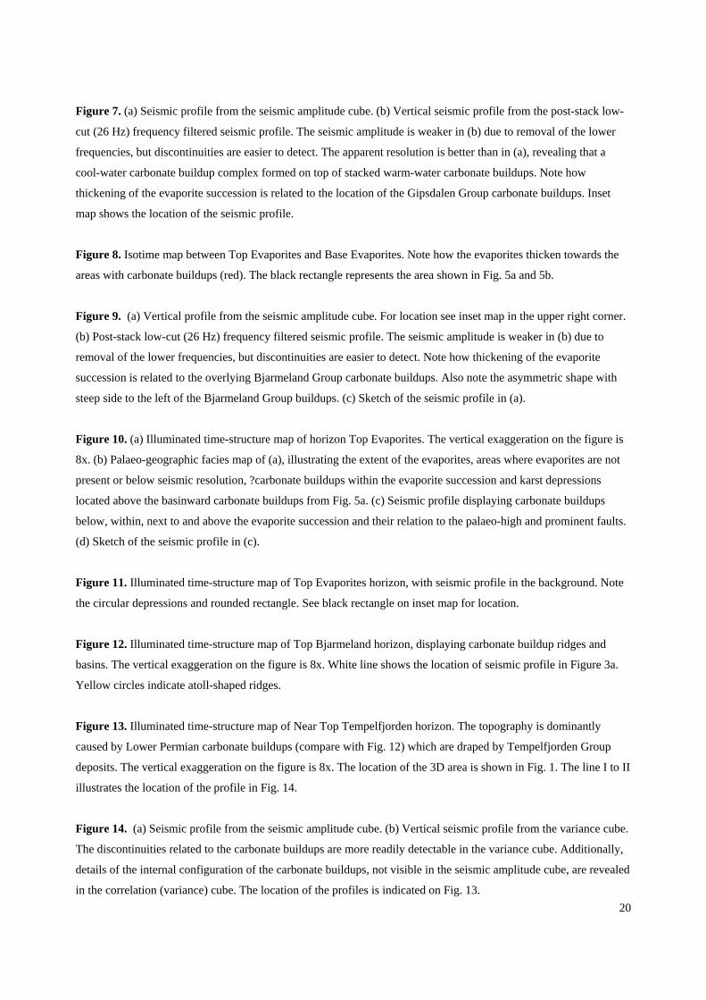
Figure 8. Isotime map between Top Evaporites and Base Evaporites. Note how the evaporites thicken towards the
areas with carbonate buildups (red). The black rectangle represents the area shown in Fig. 5a and 5b.
Figure 9. (a) Vertical profile from the seismic amplitude cube. For location see inset map in the upper right corner.
(b) Post-stack low-cut (26 Hz) frequency filtered seismic profile. The seismic amplitude is weaker in (b) due to
removal of the lower frequencies, but discontinuities are easier to detect. Note how thickening of the evaporite
succession is related to the overlying Bjarmeland Group carbonate buildups. Also note the asymmetric shape with
steep side to the left of the Bjarmeland Group buildups. (c) Sketch of the seismic profile in (a).
Figure 10. (a) Illuminated time-structure map of horizon Top Evaporites. The vertical exaggeration on the figure is
8x. (b) Palaeo-geographic facies map of (a), illustrating the extent of the evaporites, areas where evaporites are not
present or below seismic resolution, ?carbonate buildups within the evaporite succession and karst depressions
located above the basinward carbonate buildups from Fig. 5a. (c) Seismic profile displaying carbonate buildups
below, within, next to and above the evaporite succession and their relation to the palaeo-high and prominent faults.
(d) Sketch of the seismic profile in (c).
Figure 11. Illuminated time-structure map of Top Evaporites horizon, with seismic profile in the background. Note
the circular depressions and rounded rectangle. See black rectangle on inset map for location.
Figure 12. Illuminated time-structure map of Top Bjarmeland horizon, displaying carbonate buildup ridges and
basins. The vertical exaggeration on the figure is 8x. White line shows the location of seismic profile in Figure 3a.
Yellow circles indicate atoll-shaped ridges.
Figure 13. Illuminated time-structure map of Near Top Tempelfjorden horizon. The topography is dominantly
caused by Lower Permian carbonate buildups (compare with Fig. 12) which are draped by Tempelfjorden Group
deposits. The vertical exaggeration on the figure is 8x. The location of the 3D area is shown in Fig. 1. The line I to II
illustrates the location of the profile in Fig. 14.
Figure 14. (a) Seismic profile from the seismic amplitude cube. (b) Vertical seismic profile from the variance cube.
The discontinuities related to the carbonate buildups are more readily detectable in the variance cube. Additionally,
details of the internal configuration of the carbonate buildups, not visible in the seismic amplitude cube, are revealed
in the correlation (variance) cube. The location of the profiles is indicated on Fig. 13.

Fig. 1

Fig. 2

Fig. 3.

Fig. 4.

Fig. 5.

Fig. 6.

Fig. 7.
Fig.8.

Fig. 9.

Fig. 10.

Fig. 11.

Fig. 12.

Fig. 13.

Fig. 14.