Embed Size (px)
Citation preview
1GERDA Meeting at IRMM, Geel , June 10-14, 2007
From MYRRHA to XT-ADSDevelopment of LBE cooled ADS and perspective of
Implementation in Europe at Mol
Hamid Aït Abderrahim
SCK•CEN, Advanced Nuclear Systems InstituteBoeretang 200, B-2400 Mol, Belgium
2
• Introduction• MYRRHA Components• Perspectives for implementation
1. SCK-CEN Commitment2. Opening to Europe3. Fast Spectrum Irradiation Facility4. Link ADS/Gen. IV LFR5. Comprehensive Support R&D
• Roadmap for deployment• Conclusion
Summary
3
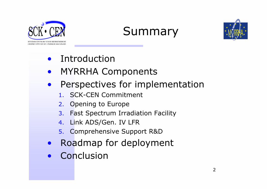
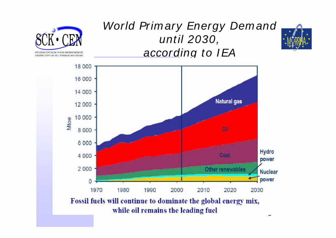
World Primary Energy Demand until 2030,
according to IEA
4
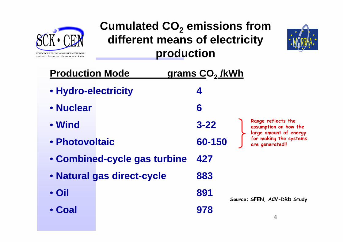
Production Mode grams CO2 /kWh
• Hydro-electricity 4
• Nuclear 6
• Wind 3-22
• Photovoltaic 60-150
• Combined-cycle gas turbine 427
• Natural gas direct-cycle 883
• Oil 891
• Coal 978
Cumulated CO2 emissions from different means of electricity
production
Source: SFEN, ACV-DRD Study
Range reflects the assumption on how thelarge amount of energyfor making the systemsare generated!!
5
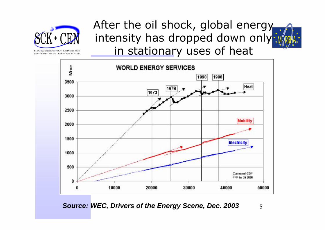
After the oil shock, global energy intensity has dropped down only
in stationary uses of heat
Source: WEC, Drivers of the Energy Scene, Dec. 2003
6
-60
-40
-20
0
20
40
60
80
0 10 20 30 40 50 60 70 80 90
FranceBelgium
Sweden
Switzerland
Finland
Germany
Japan
UK
Norway
Italy
US
Canada
World Average
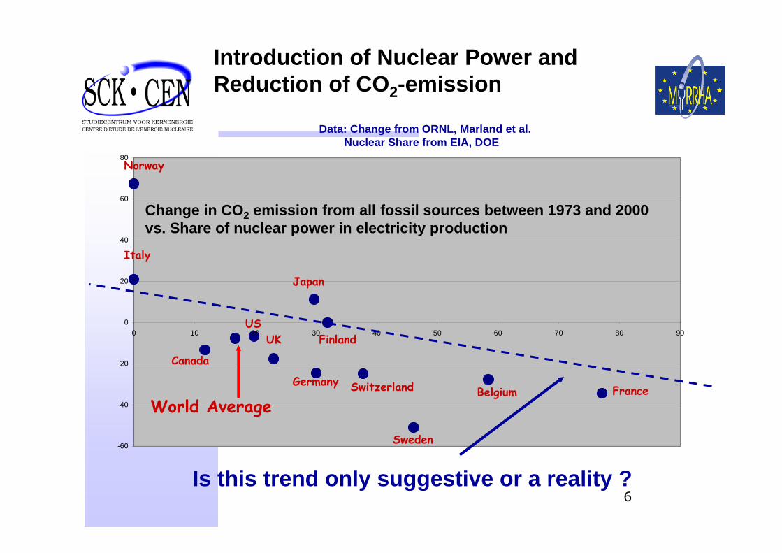
Introduction of Nuclear Power and Reduction of CO2-emission
Change in CO2 emission from all fossil sources between 1973 and 2000vs. Share of nuclear power in electricity production
Data: Change from ORNL, Marland et al.Nuclear Share from EIA, DOE
Is this trend only suggestive or a reality ?
7
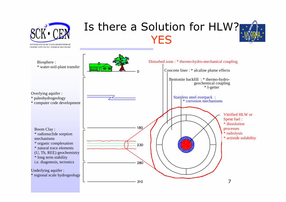
Is there a Solution for HLW? YES
Vitrified HLW orSpent fuel :* dissolutionprocesses* radiolysis* actinide solubility
* I-getter
Underlying aquifer :* regional scale hydrogeology
Overlying aquifer :* paleohydrogeology* computer code development
Biosphere :* water-soil-plant transfer
Disturbed zone : * thermo-hydro-mechanical coupling
Concrete liner : * alcaline plume effects
Stainless steel overpack :* corrosion mechanisms
Bentonite backfill : * thermo-hydro-geochemical coupling
Boom Clay :* radionuclide sorptionmechanisms* organic complexation* natural trace elements(U, Th, REE) geochemistry* long term stabilityi.e. diagenesis, tectonics
8
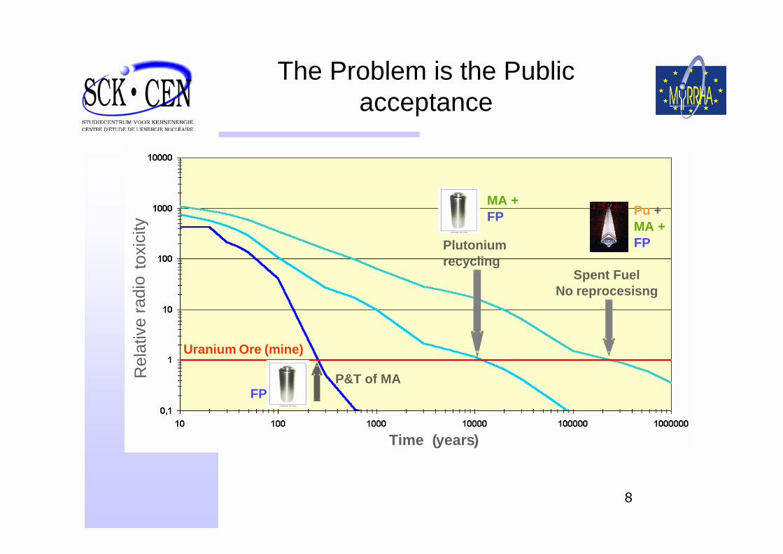
The Problem is the Public acceptance
Plutonium recycling
Spent FuelNo reprocesisng
Uranium Ore (mine)
Time (years)
Rel
ativ
e ra
dio
toxi
city
P&T of MA
Pu +MA +FP
MA +FP
FP
9
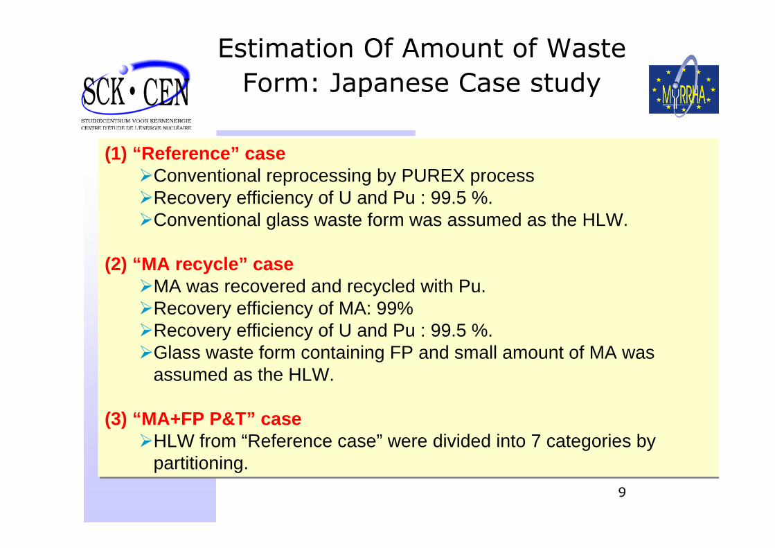
Estimation Of Amount of Waste Form: Japanese Case study
(1) “Reference” caseConventional reprocessing by PUREX process Recovery efficiency of U and Pu : 99.5 %. Conventional glass waste form was assumed as the HLW.
(2) “MA recycle” caseMA was recovered and recycled with Pu.Recovery efficiency of MA: 99%Recovery efficiency of U and Pu : 99.5 %. Glass waste form containing FP and small amount of MA was assumed as the HLW.
(3) “MA+FP P&T” caseHLW from “Reference case” were divided into 7 categories by partitioning.
10
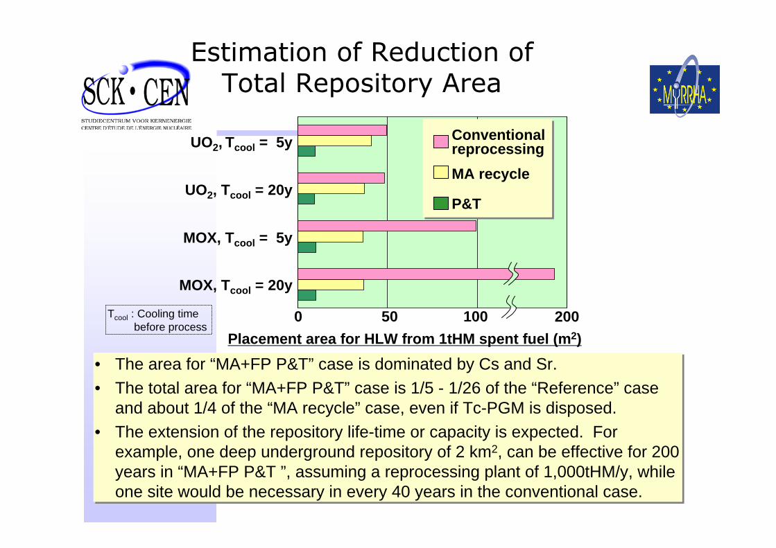
Estimation of Reduction of Total Repository Area
UO2, Tcool = 5y
UO2, Tcool = 20y
MOX, Tcool = 5y
MOX, Tcool = 20y
0 50 100 200Placement area for HLW from 1tHM spent fuel (m2)
Conventional reprocessing MA recycle
P&T
Tcool : Cooling time before process
• The area for “MA+FP P&T” case is dominated by Cs and Sr.• The total area for “MA+FP P&T” case is 1/5 - 1/26 of the “Reference” case
and about 1/4 of the “MA recycle” case, even if Tc-PGM is disposed. • The extension of the repository life-time or capacity is expected. For
example, one deep underground repository of 2 km2, can be effective for 200 years in “MA+FP P&T ”, assuming a reprocessing plant of 1,000tHM/y, while one site would be necessary in every 40 years in the conventional case.
11
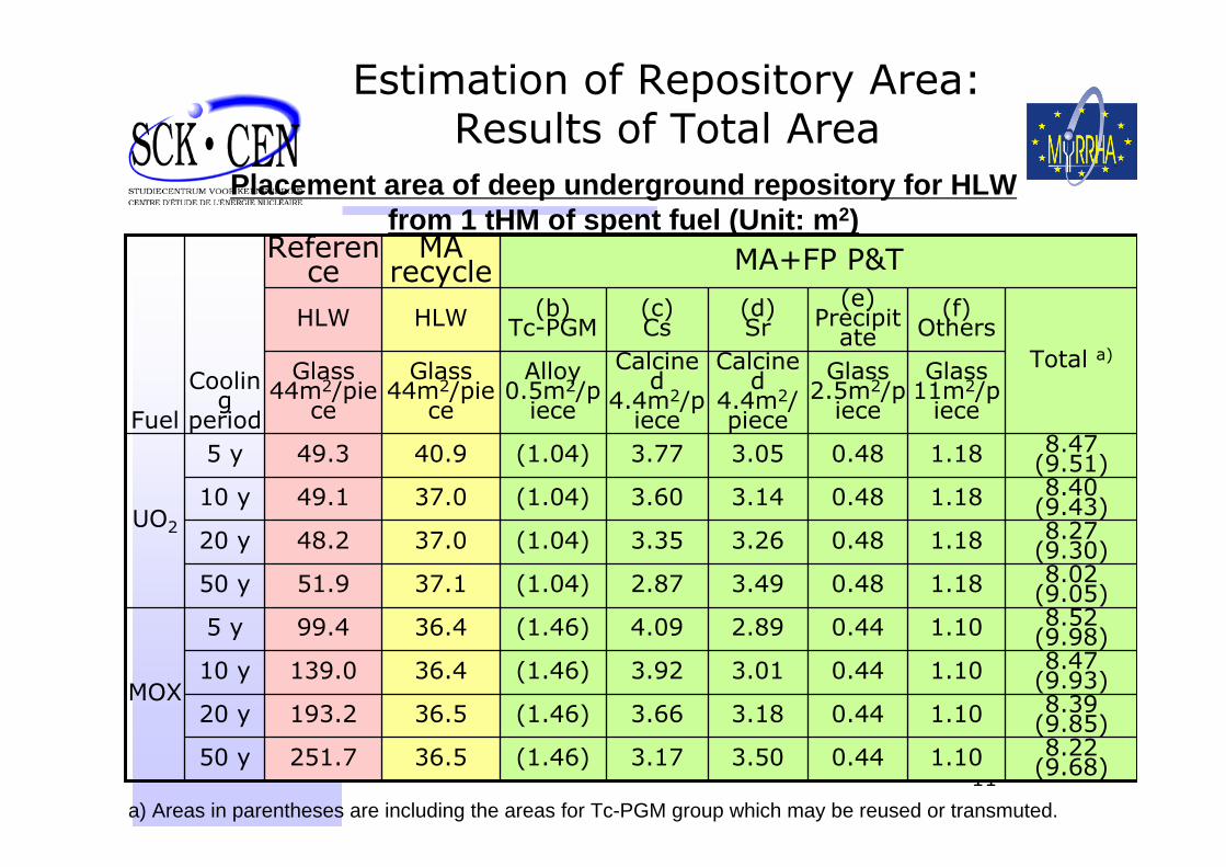
Estimation of Repository Area:Results of Total Area
Total a)
(f)Others
(e)Precipit
ate(d)Sr
(c)Cs
(b)Tc-PGMHLWHLW
1.10
1.10
1.10
1.10
1.18
1.18
1.18
1.18
Glass11m2/p
iece
8.22 (9.68)
8.39 (9.85)
8.47 (9.93)
8.52 (9.98)
8.02 (9.05)
8.27 (9.30)
8.40 (9.43)
8.47 (9.51)
3.17
3.66
3.92
4.09
2.87
3.35
3.60
3.77
Calcined
4.4m2/piece
0.443.50(1.46)36.5251.750 y
0.443.01(1.46)36.4139.010 y
0.483.14(1.04)37.049.110 y
0.483.49(1.04)37.151.950 y
MOX
UO2
Fuel
0.44
0.44
0.48
0.48
Glass2.5m2/p
iece
3.18
2.89
3.26
3.05
Calcined
4.4m2/piece
Alloy0.5m2/p
iece
Glass44m2/pie
ce
Glass44m2/pie
ce
(1.46)36.5193.220 y
(1.46)36.499.45 y
(1.04)37.048.220 y
(1.04)40.949.35 y
MA+FP P&TMA recycle
Reference
Cooling
period
Placement area of deep underground repository for HLW from 1 tHM of spent fuel (Unit: m2)
a) Areas in parentheses are including the areas for Tc-PGM group which may be reused or transmuted.
12
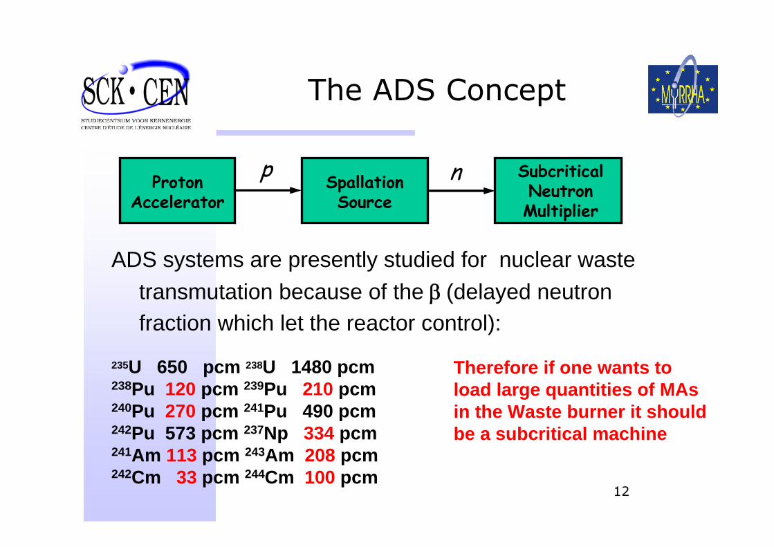
The ADS Concept
ProtonAccelerator
SubcriticalNeutronMultiplier
SpallationSource
p n
ADS systems are presently studied for nuclear waste transmutation because of the β (delayed neutron fraction which let the reactor control):
235U 650 pcm 238U 1480 pcm238Pu 120 pcm 239Pu 210 pcm240Pu 270 pcm 241Pu 490 pcm242Pu 573 pcm 237Np 334 pcm241Am 113 pcm 243Am 208 pcm242Cm 33 pcm 244Cm 100 pcm
Therefore if one wants to load large quantities of MAs in the Waste burner it should be a subcritical machine

13
The ADS Principle
14
SCK•CEN Competencies
• SCK•CEN core competencies: design, realisation and operation of large nuclear research facilities (BR1, BR2, BR3, VENUS reactors, Pu-Lab, LHMA Hot cells, HADES URL for waste Mgt).
• BR2, a 100 MW MTR, will soon be 45 years old, like other major MTRs in Europe (OSIRIS, HFR, R2).
• SCK•CEN and IBA have been associated to develop the ADONIS project during the 1995-97 period. ADONIS was a ~1.5 MW ADS with 0.15 to 0.3 MW low energy proton beam power (1 to 2 mA * 150 MeV) for Radioisotopes production
15
MYRRHA in a European scene
• the RJH (F) project, a thermal spectrum MTR, is the only planned testing reactor for the moment
• MYRRHA would be the natural fast spectrum complementary facility.
• This will put Europe in a strong position towards the support of Gen. III and development of Gen. IV reactors.
16
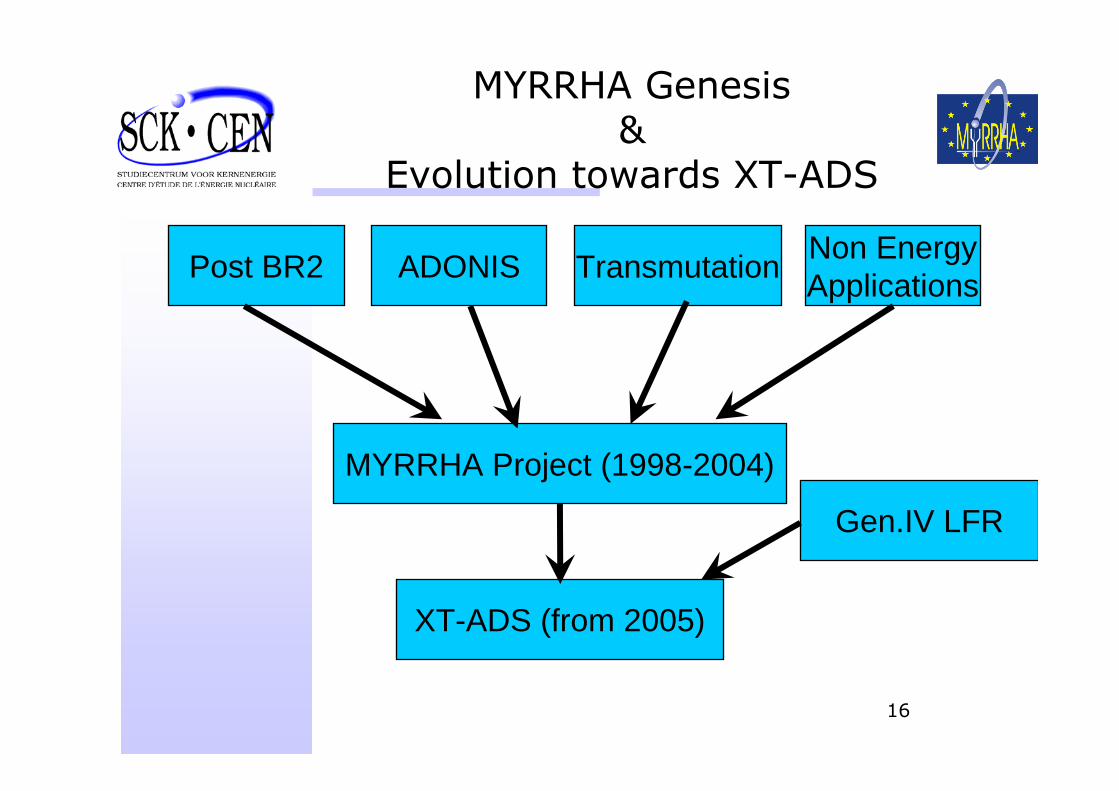
MYRRHA Genesis &
Evolution towards XT-ADS
Post BR2 ADONIS Transmutation Non EnergyApplications
MYRRHA Project (1998-2004)
XT-ADS (from 2005)
Gen.IV LFR
17
The Applications catalogue: MYRRHA/XT-ADS is to be:
• A full step ADS demo facility
• A P&T testing facility
• A flexible irradiation testing facility in replacement of the SCK CEN MTR BR2 (100 MW)
• An attractive fast spectrum testing facility in Europe, beyond 2015 complementary to RJH (F)
• HLM Technological prototype as test bench for LFR
• An attractive tool for education and training of young scientists and engineers
• A medical radioisotope production facility
18
MYRRHA/XT-ADSComponents
• ACCELERATOR• SPALLATION SOURCE• SUB-CRITICAL REACTOR• REMOTE HANDLING & IN-
SERVICE INSPECTION
19
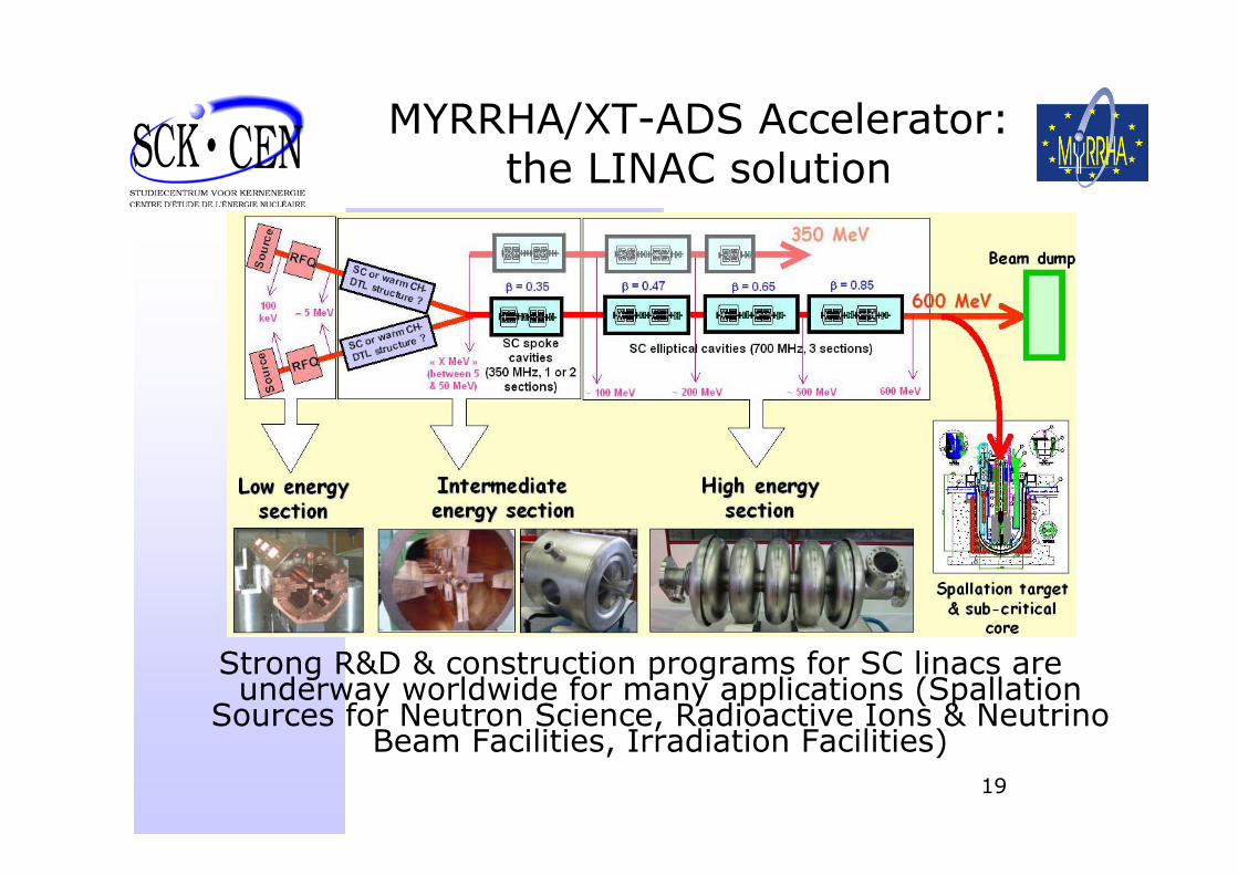
MYRRHA/XT-ADS Accelerator:the LINAC solution
Strong R&D & construction programs for SC linacs are underway worldwide for many applications (Spallation
Sources for Neutron Science, Radioactive Ions & Neutrino Beam Facilities, Irradiation Facilities)
20
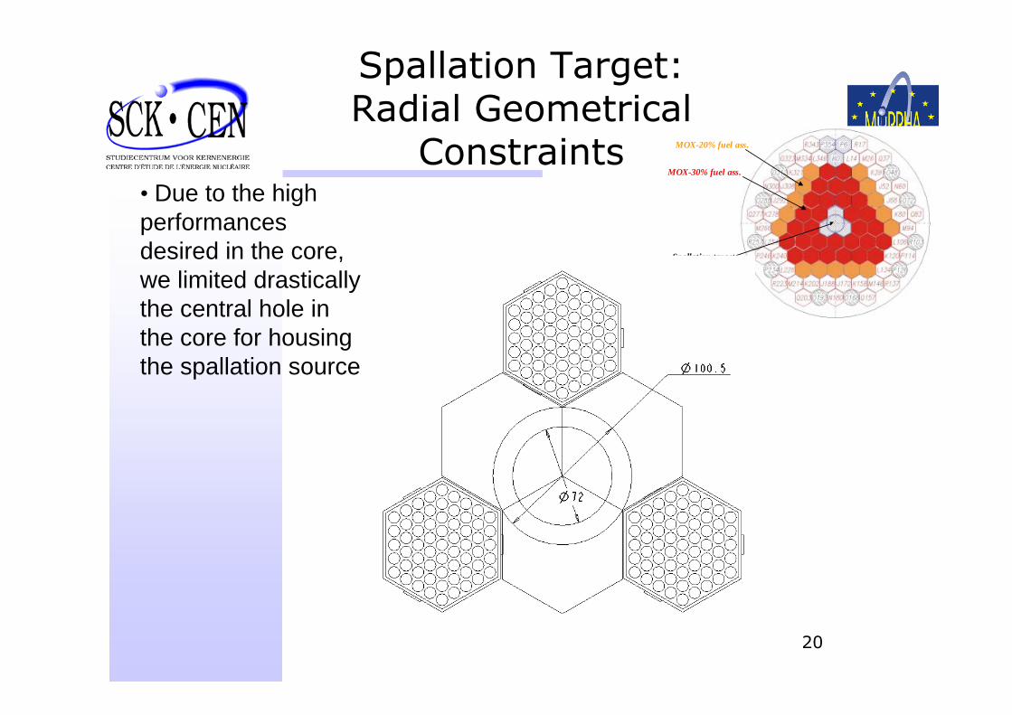
Spallation Target:Radial Geometrical
Constraints MOX-20% fuel ass.
MOX-30% fuel ass.
Spallation target
• Due to the high performances desired in the core, we limited drastically the central hole in the core for housing the spallation source
21
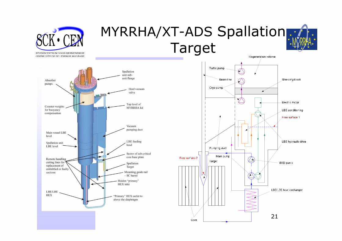
MYRRHA/XT-ADS Spallation Target
22
Sub-Critical Reactor Pb-Bi: benefits and drawbacks
☺Undergoes spallation ☺Reasonable melting temperature (123 °C)☺Water can be used for the secondary cooling
High coolant density (steel and fuel float)Opaque: blind fuel handlingPossible problems in case of variation of the eutectic composition (deposits of high melting point phases)Bi activates into PoThe compatibility of Pb-Bi with structural and cladding materials is to be addressed by design
23
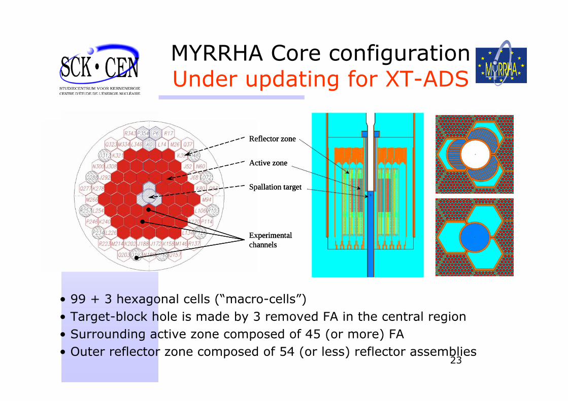
MYRRHA Core configurationUnder updating for XT-ADS
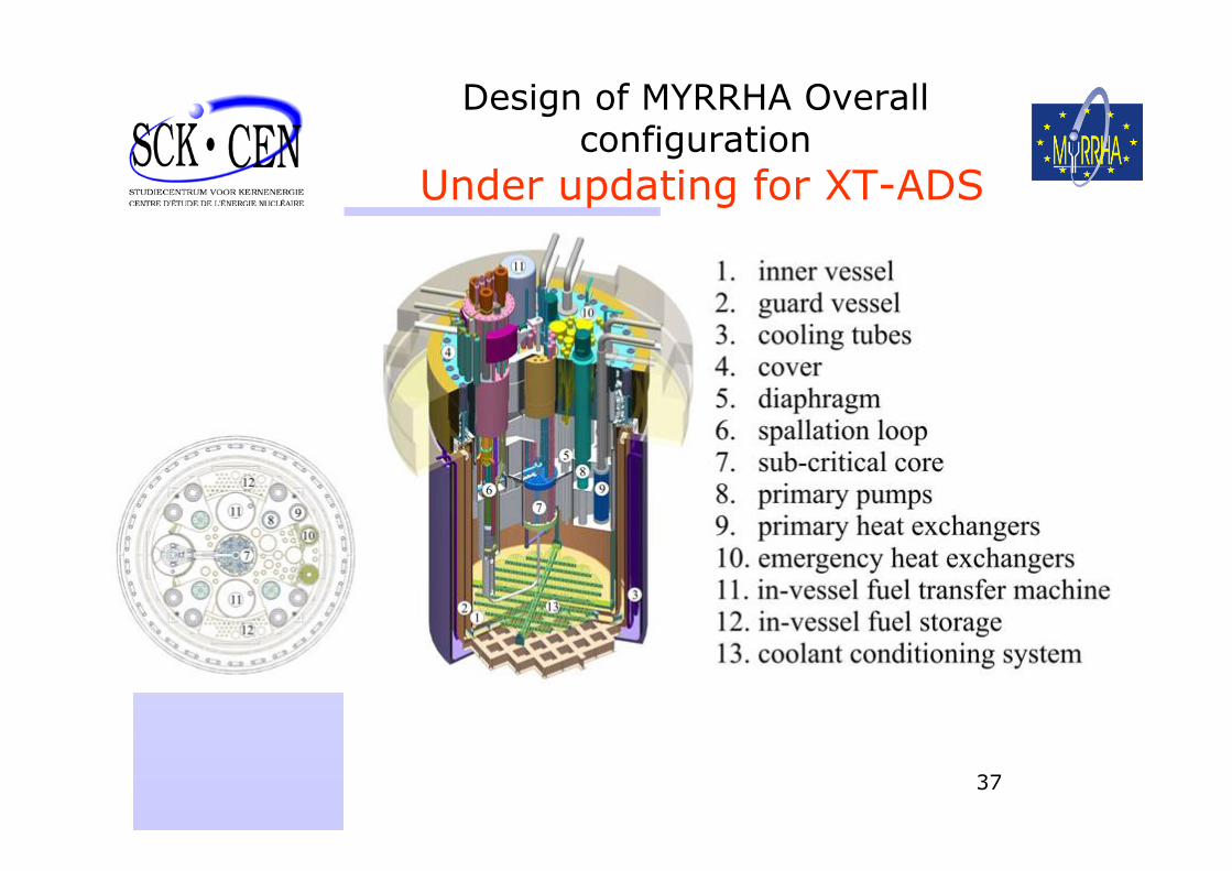
• 99 + 3 hexagonal cells (“macro-cells”) • Target-block hole is made by 3 removed FA in the central region • Surrounding active zone composed of 45 (or more) FA• Outer reflector zone composed of 54 (or less) reflector assemblies
Experimental channels
Reflector zone
Active zone
Spallation target
Experimental channels
Reflector zone
Active zone
Spallation target
Experimental channels
Reflector zone
Active zone
Spallation target
24
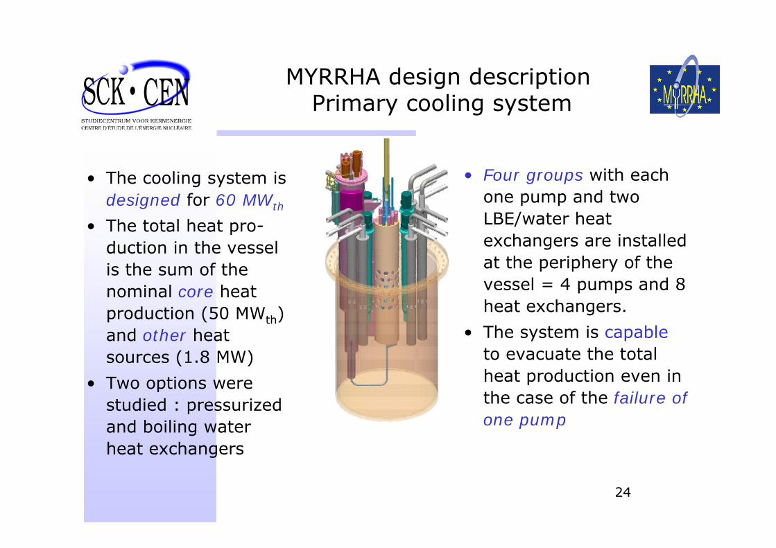
MYRRHA design description Primary cooling system
• The cooling system is designed for 60 MWth
• The total heat pro-duction in the vessel is the sum of the nominal core heat production (50 MWth) and other heat sources (1.8 MW)
• Two options were studied : pressurized and boiling water heat exchangers
• Four groups with each one pump and two LBE/water heat exchangers are installed at the periphery of the vessel = 4 pumps and 8 heat exchangers.
• The system is capableto evacuate the total heat production even in the case of the failure of one pump
25
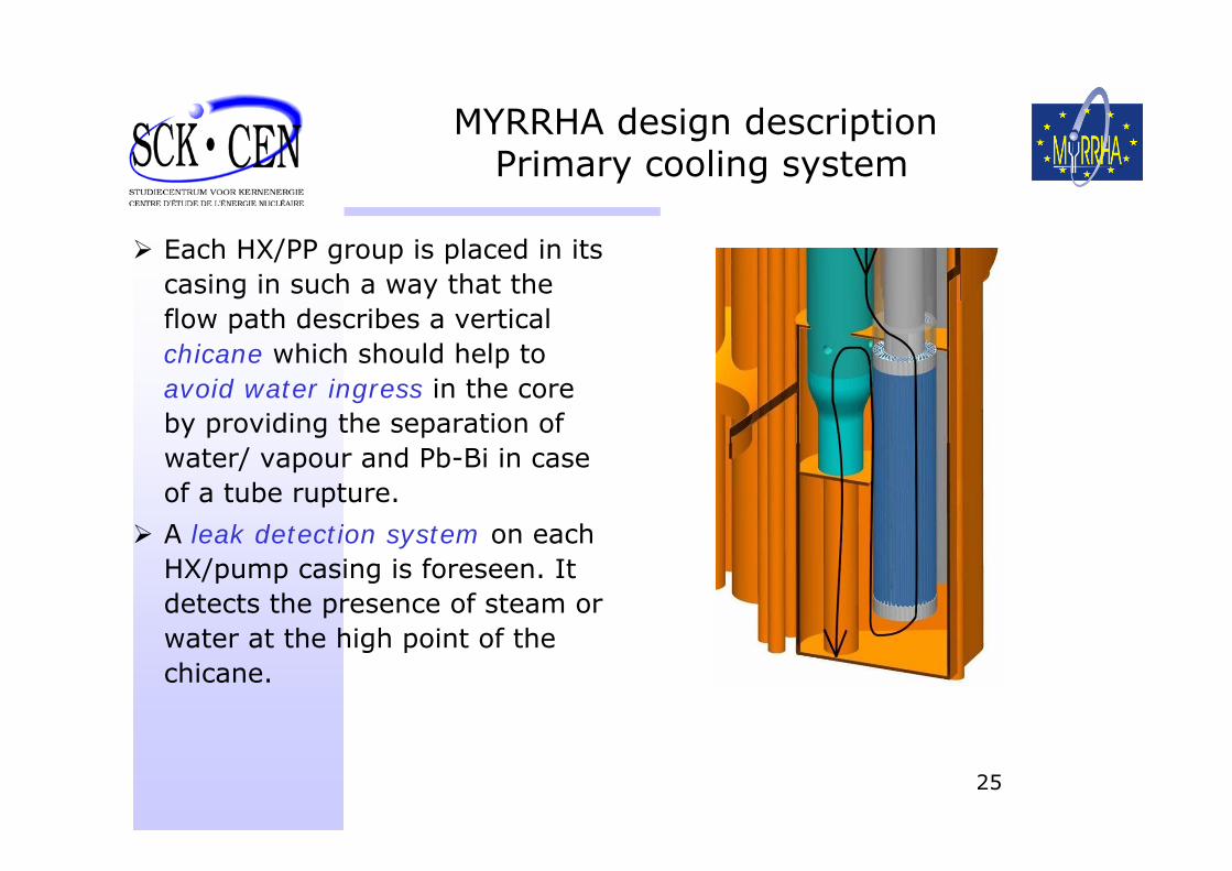
MYRRHA design description Primary cooling system
Each HX/PP group is placed in its casing in such a way that the flow path describes a vertical chicane which should help to avoid water ingress in the core by providing the separation of water/ vapour and Pb-Bi in case of a tube rupture.
A leak detection system on each HX/pump casing is foreseen. It detects the presence of steam or water at the high point of the chicane.
26
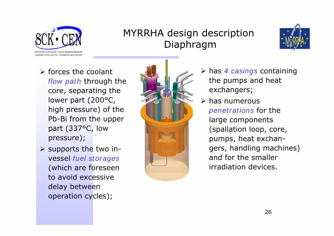
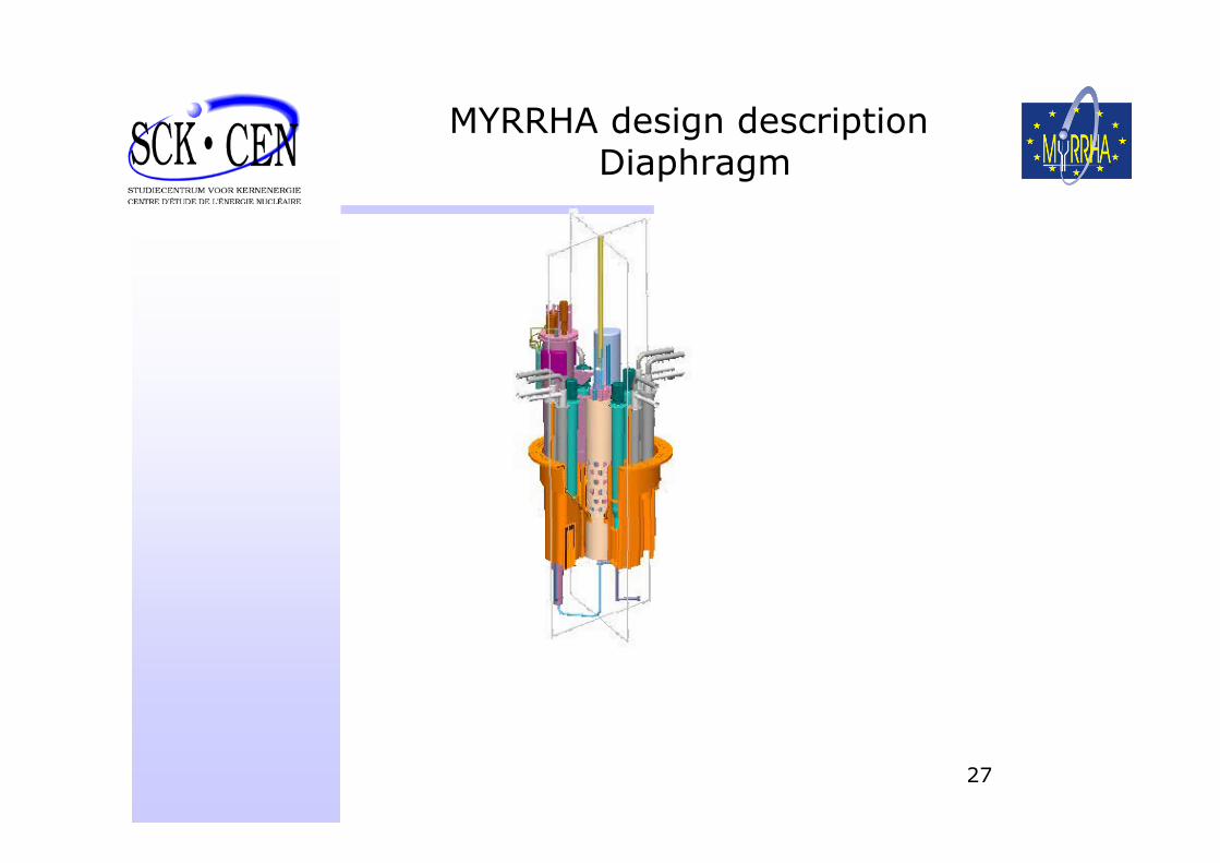
MYRRHA design description Diaphragm
forces the coolant flow path through the core, separating the lower part (200°C, high pressure) of the Pb-Bi from the upper part (337°C, low pressure);
supports the two in-vessel fuel storages(which are foreseen to avoid excessive delay between operation cycles);
has 4 casings containing the pumps and heat exchangers;
has numerous penetrations for the large components (spallation loop, core, pumps, heat exchan-gers, handling machines) and for the smaller irradiation devices.
27
MYRRHA design description Diaphragm
28
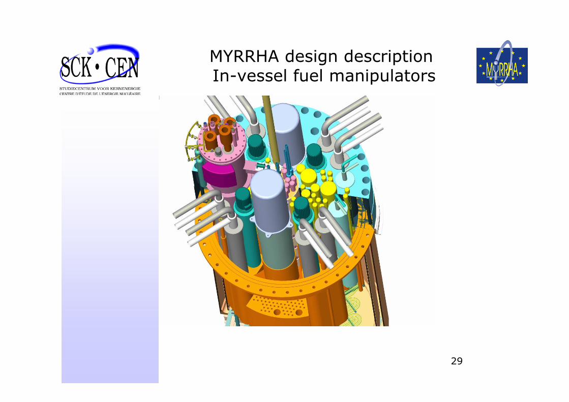
MYRRHA design description In-vessel fuel manipulators
The fuel handling is performed underneath the core:• because the irradiation devices (inside the core and in the
periphery of the core as well) will stay several cycles in the reactor and because their handling will be a difficult process, it is wished to keep them into location while reloading the core – this makes fuel manipulation above the core very impractically;
• the room situated directly above the compact core will be occupied by instrumentation, the beam tube and partially by the spallation loop, with which the fuel handling would interfere if performed from the top of the core,
• the interlinking of the spallation loop with the core makes some fuel assembly positions inaccessible from above,
The fuel assemblies rest by buoyancy force under the support plate.
29
MYRRHA design description In-vessel fuel manipulators
30
MYRRHA design description In-vessel fuel manipulators
31
MYRRHA design description In-vessel fuel manipulators
32
MYRRHA design description In-vessel fuel manipulators
33
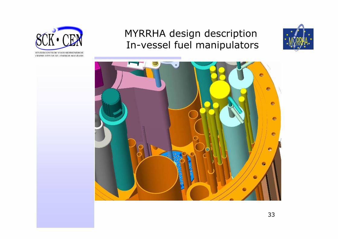
MYRRHA design description In-vessel fuel manipulators
34
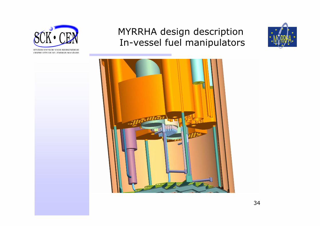
MYRRHA design description In-vessel fuel manipulators
35
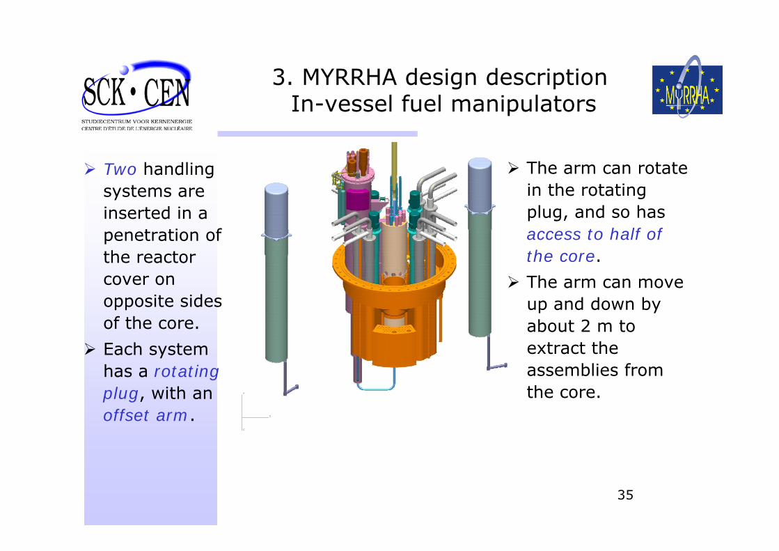
3. MYRRHA design description In-vessel fuel manipulators
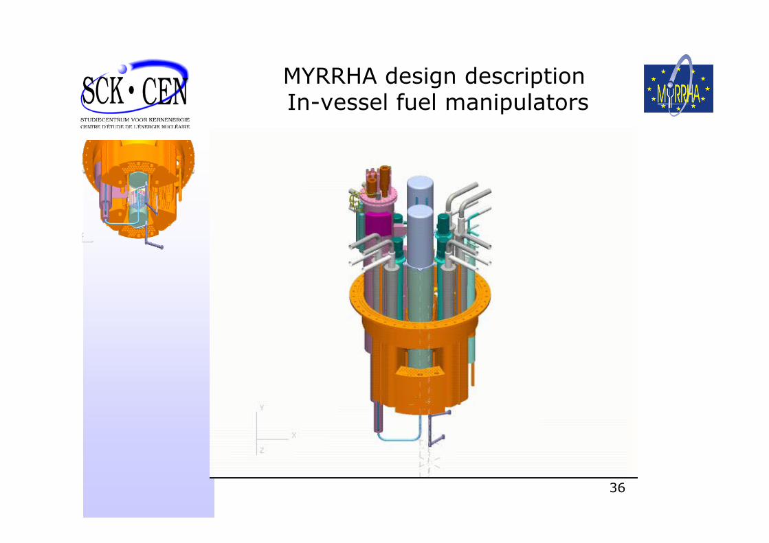
Two handling systems are inserted in a penetration of the reactor cover on opposite sides of the core.
Each system has a rotating plug, with an offset arm.
The arm can rotate in the rotating plug, and so has access to half of the core.
The arm can move up and down by about 2 m to extract the assemblies from the core.
36
MYRRHA design description In-vessel fuel manipulators
37
Design of MYRRHA Overall configuration
Under updating for XT-ADS
38
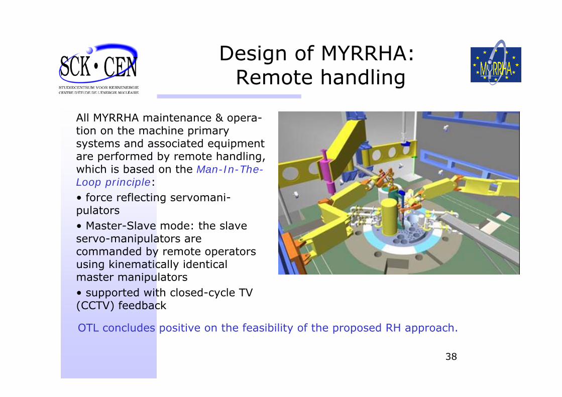
Design of MYRRHA:Remote handling
All MYRRHA maintenance & opera-tion on the machine primary systems and associated equipment are performed by remote handling, which is based on the Man-In-The-Loop principle:• force reflecting servomani-pulators • Master-Slave mode: the slave servo-manipulators are commanded by remote operators using kinematically identical master manipulators • supported with closed-cycle TV (CCTV) feedback
OTL concludes positive on the feasibility of the proposed RH approach.
39
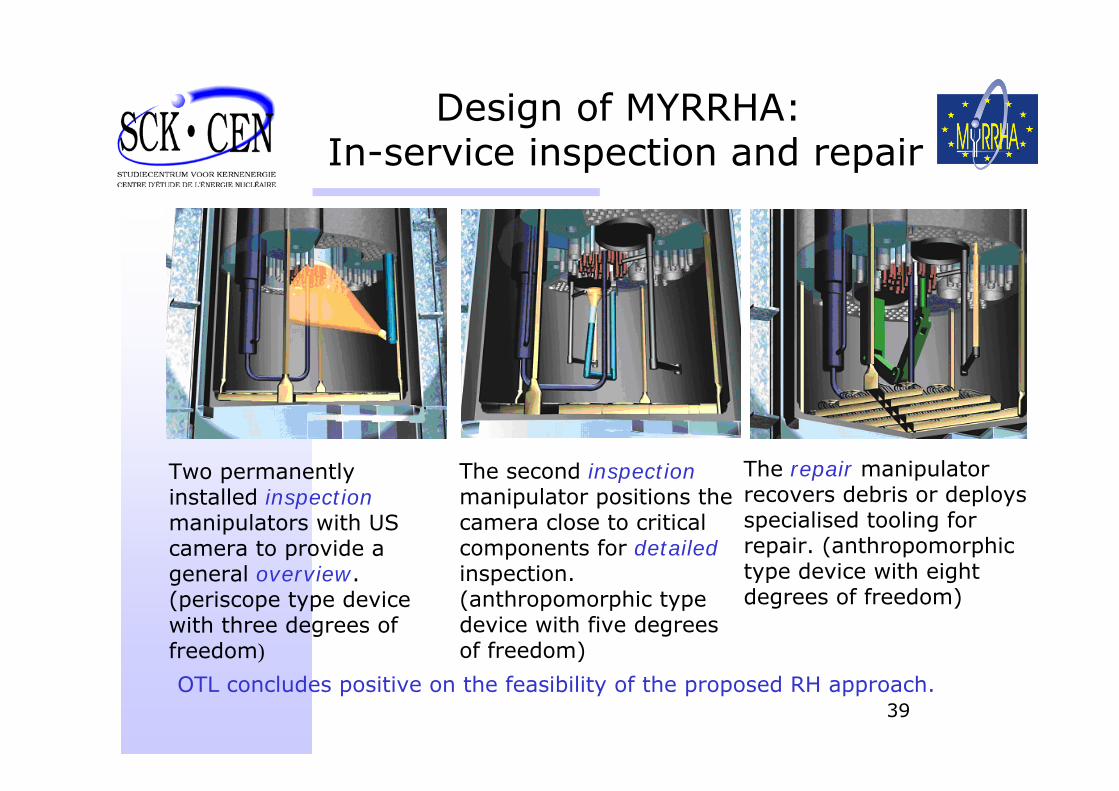
Design of MYRRHA:In-service inspection and repair
Two permanentlyinstalled inspectionmanipulators with US camera to provide a general overview. (periscope type device with three degrees of freedom)
The second inspectionmanipulator positions the camera close to critical components for detailedinspection. (anthropomorphic type device with five degrees of freedom)
The repair manipulator recovers debris or deploys specialised tooling for repair. (anthropomorphic type device with eight degrees of freedom)
OTL concludes positive on the feasibility of the proposed RH approach.
40
Perspectives for Implementation
41
1-SCK•CEN Commitment
• SCK•CEN Mgt has declared its readiness to welcome a fast spectrum irradiation facility at its technical site in Mol
• SCK•CEN has finished the preparation of a business plan and a funding plan that has been made available to the Belgian Government in May 2007 and will be presented to potential partners by autumn 2007
• Bilateral discussions with some potential partners are already going on (CNRS, CEA, CIEMAT, …)
42
2-Opening MYRRHA to Europe => XT-ADS
• MYRRHA Draft-2 has been made available to the EUROTRANS Community
• SCK•CEN is studying in collaboration with EUROTRANS partners the modifications needed to achieve the XT-ADS objectives
• Considering Joint Undertaking for setting up the frame for the realisationat European level
43
The reference architecture of the primary system as decided during Eurotrans DCC_2 meeting (Lyon 10/2006):
Modifications with respect to MYRRHA (between brackets)• primary system capable to extract 70 MWth total heat power
(60 MWth)• core inlet and outlet LBE cooling temperatures : 300°C – 400°C
(200°C – 340°C)• improved natural convection in case of PLOH by:
core pressure drop Δp limited to 1000 mbarincreased elevation between PHX & core to 2 m
• simplified flat diaphragm• reduced number of primary components to 2 groups to reduce
costs (4 groups)
2. XT-ADS design descriptionReference architecture
44
Modifications with respect to MYRRHA (cont'd)• reduced number of possible IPS in the core to 8 possible
positions (19 positions)
• no test rigs positions outside the core(many positions outside the core)
• boiling water heat exchangers at lowest possible pressure• decay heat removal (DHR) through PHX/secondary loops + vault
cooling system (RVACS)(emergency heat exchangers)
• hanging vessel with elliptical bottom head(standing vessel with flat bottom)
• LBE cold plenum has free level (0.5 m underneath vessel top)• LBE hot free level is 1 m underneath cold free level (= Δp core)
2. XT-ADS design descriptionReference architecture
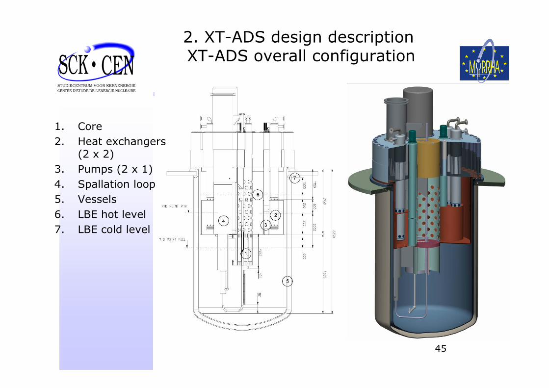
45
1. Core2. Heat exchangers
(2 x 2)3. Pumps (2 x 1)4. Spallation loop5. Vessels6. LBE hot level7. LBE cold level
2. XT-ADS design descriptionXT-ADS overall configuration
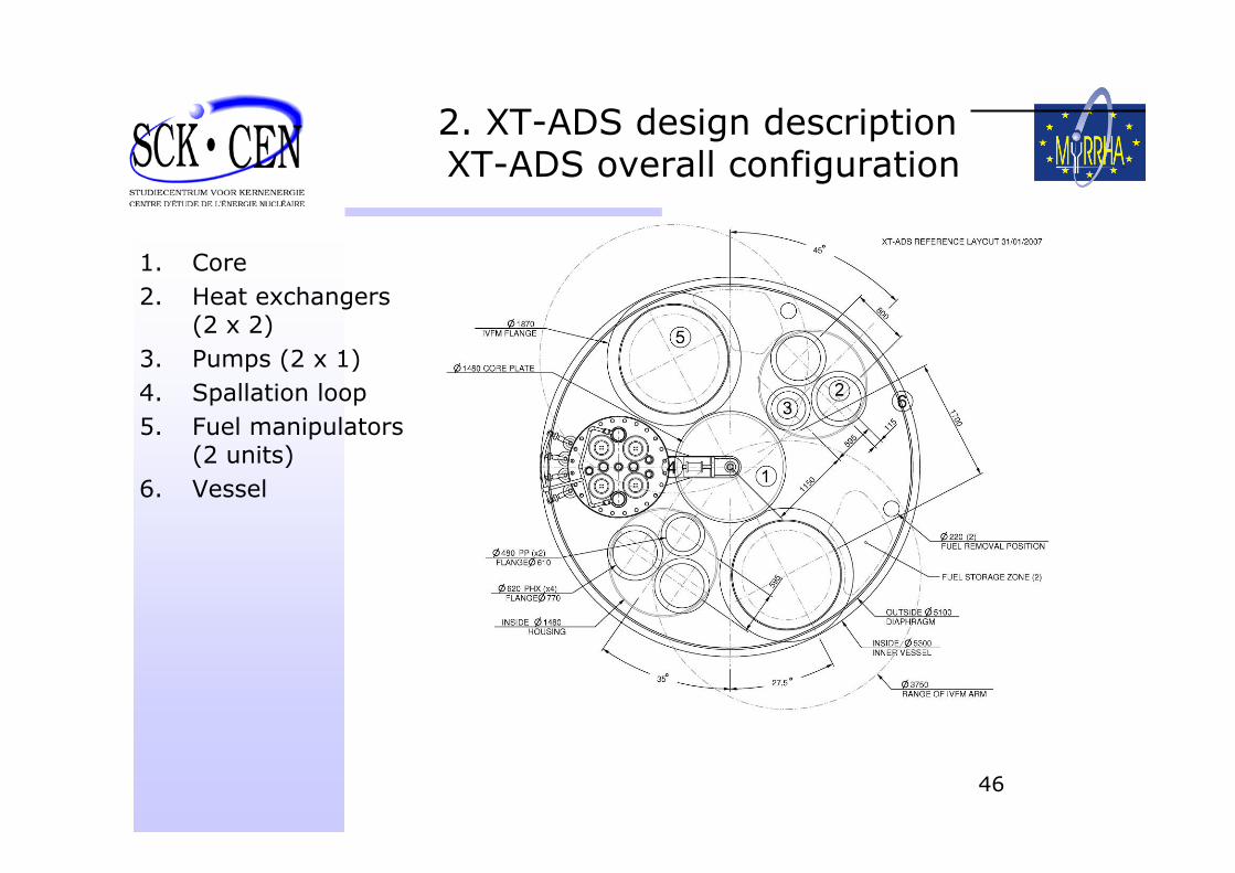
46
1. Core2. Heat exchangers
(2 x 2)3. Pumps (2 x 1)4. Spallation loop5. Fuel manipulators
(2 units)6. Vessel
2. XT-ADS design descriptionXT-ADS overall configuration
47
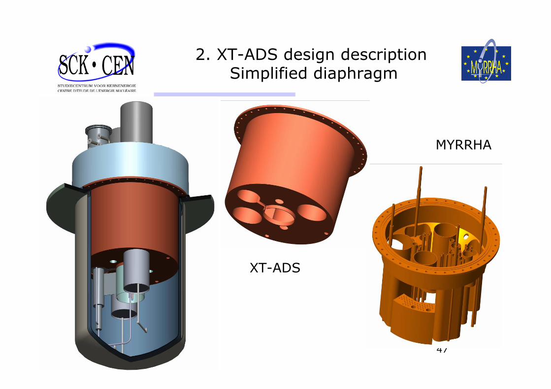
2. XT-ADS design descriptionSimplified diaphragm
XT-ADS
MYRRHA

48
3. Holding the objective of Fast irradiation facility
• Multi-irradiation channels available• High performance levels• Multiple irradiation conditions secured
to the user
49
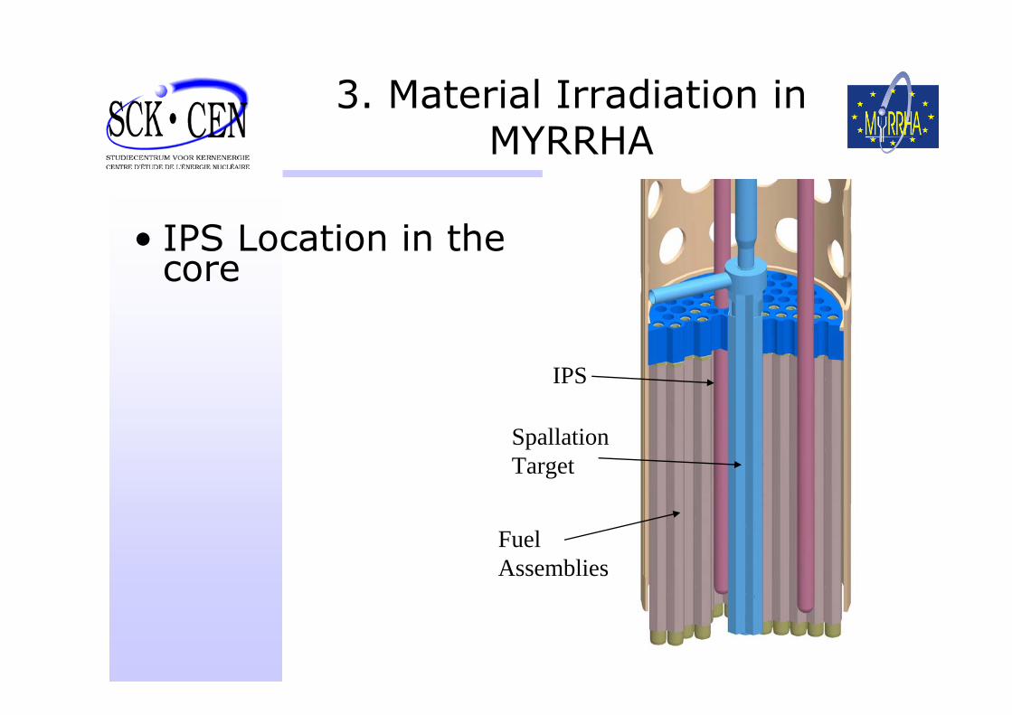
3. Material Irradiation in MYRRHA
• IPS Location in the core
IPS
Spallation Target
Fuel Assemblies
50
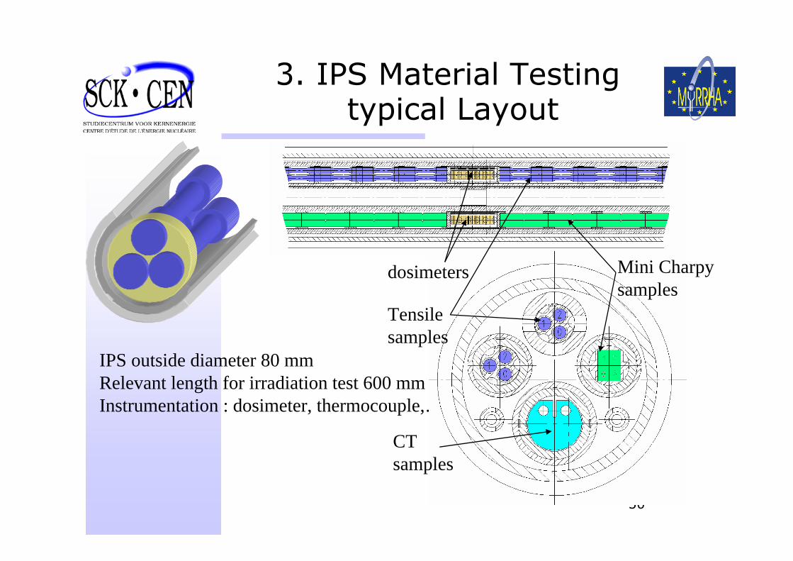
3. IPS Material Testing typical Layout
IPS outside diameter 80 mmRelevant length for irradiation test 600 mmInstrumentation : dosimeter, thermocouple,…
dosimeters
Tensilesamples
CTsamples
Mini Charpysamples
51
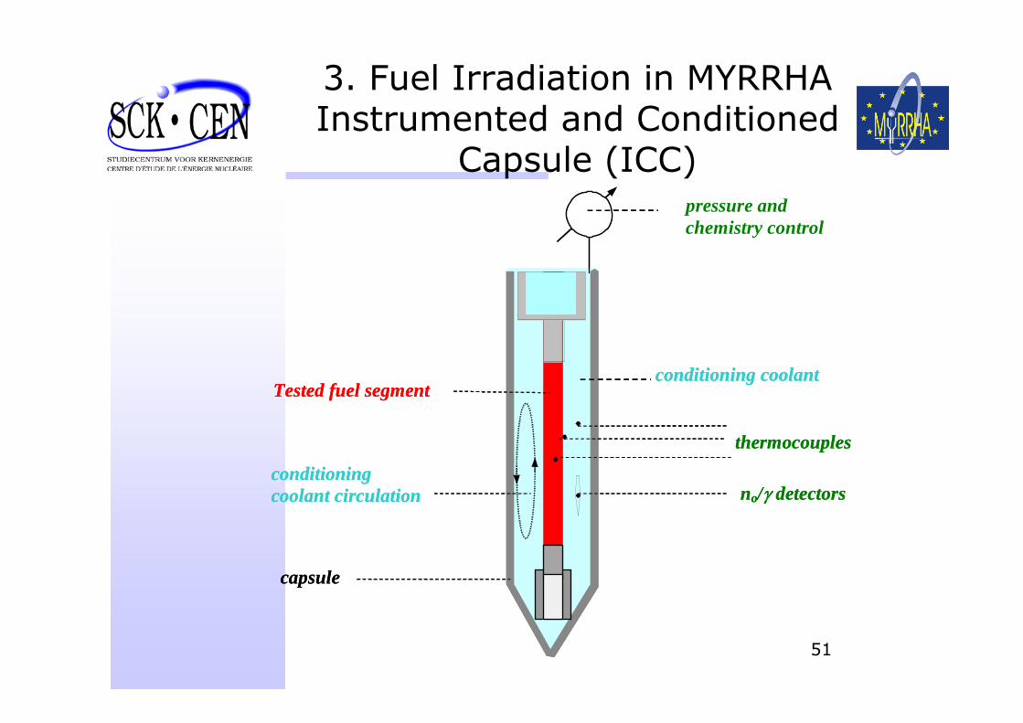
3. Fuel Irradiation in MYRRHAInstrumented and Conditioned
Capsule (ICC)
thermocouples
conditioning coolant circulation
Tested fuel segment
no/γ detectors
capsule
pressure and chemistry control
conditioning coolant
thermocouples
conditioning coolant circulation
Tested fuel segment
no/γ detectors
capsule
pressure and chemistry control
conditioning coolant
52
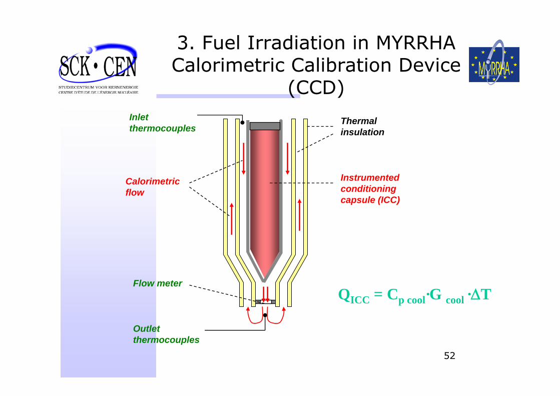
3. Fuel Irradiation in MYRRHACalorimetric Calibration Device
(CCD)Inlet thermocouples
Instrumented conditioning capsule (ICC)
Outletthermocouples
Flow meter
Calorimetricflow
Thermalinsulation
QICC = Cp cool·G cool ·ΔT
53
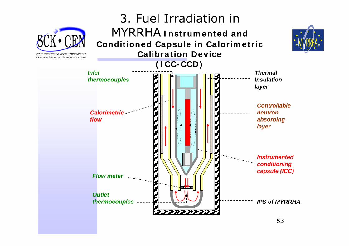
3. Fuel Irradiation in MYRRHA Instrumented and
Conditioned Capsule in Calorimetric Calibration Device
(ICC-CCD)Inlet thermocouples
Instrumented conditioning capsule (ICC)
Outletthermocouples
Flow meter
Calorimetricflow
ThermalInsulationlayer
Controllable neutron absorbinglayer
IPS of MYRRHA
54
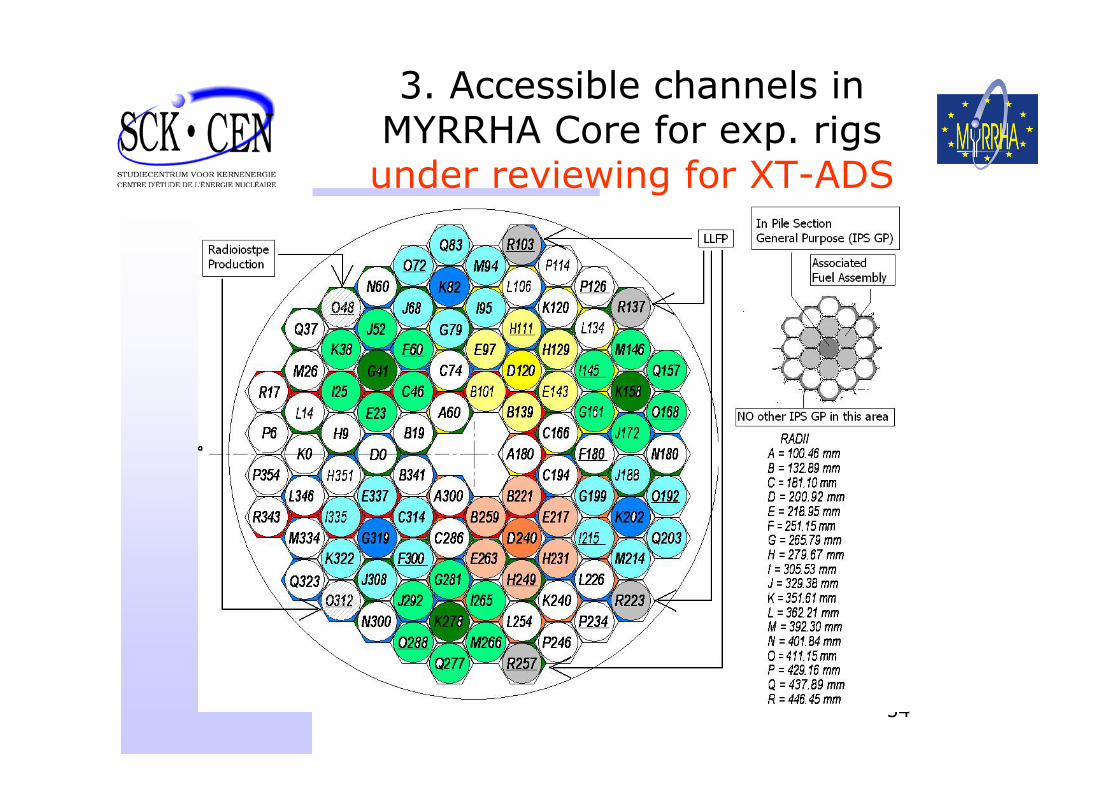
3. Accessible channels in MYRRHA Core for exp. rigs under reviewing for XT-ADS
55
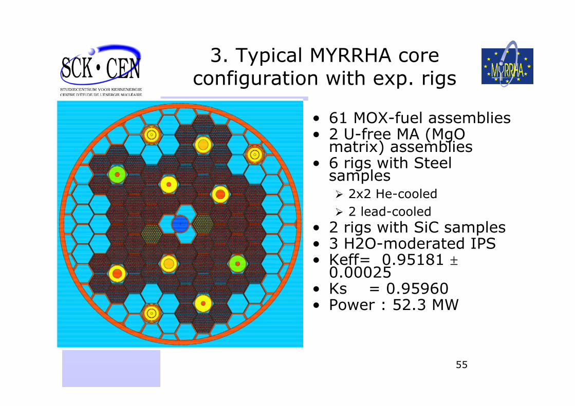
3. Typical MYRRHA core configuration with exp. rigs
• 61 MOX-fuel assemblies• 2 U-free MA (MgO
matrix) assemblies• 6 rigs with Steel
samples2x2 He-cooled 2 lead-cooled
• 2 rigs with SiC samples• 3 H2O-moderated IPS• Keff= 0.95181 ±
0.00025• Ks = 0.95960• Power : 52.3 MW
56
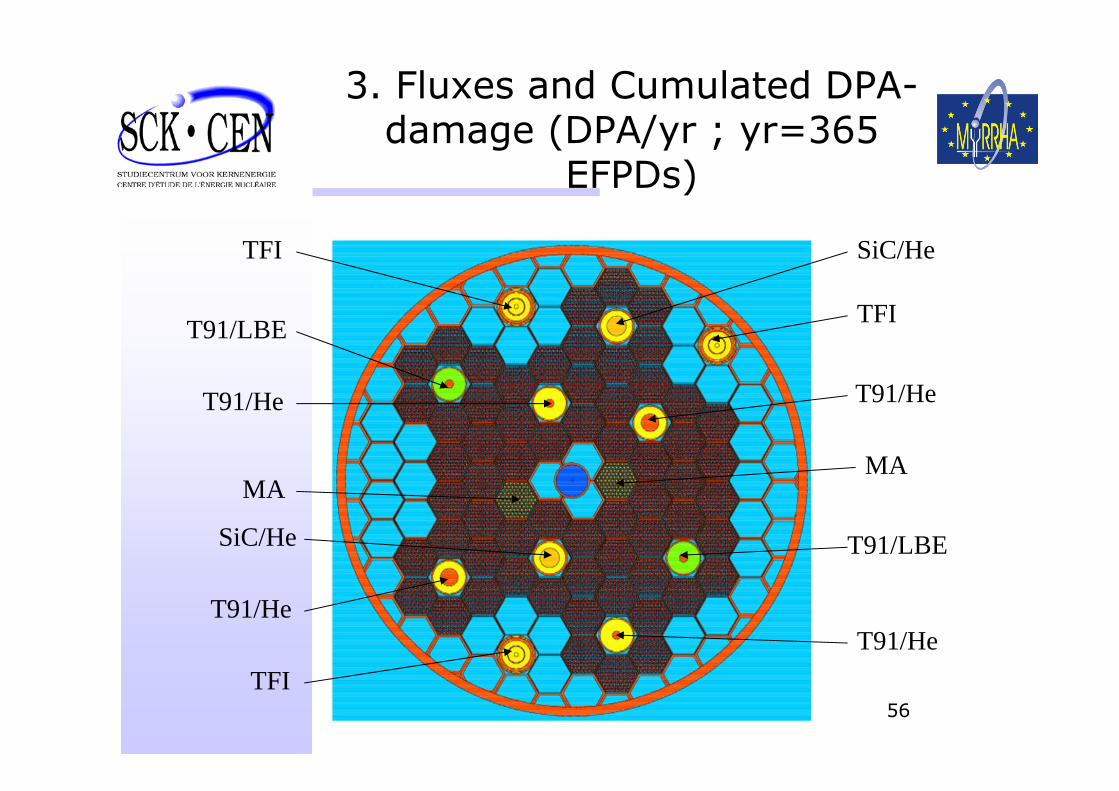
3. Fluxes and Cumulated DPA-damage (DPA/yr ; yr=365
EFPDs)
SiC/He
SiC/He
TFI
TFI
TFI
T91/He
T91/He
T91/He
T91/He
T91/LBE
T91/LBE
MAMA
57
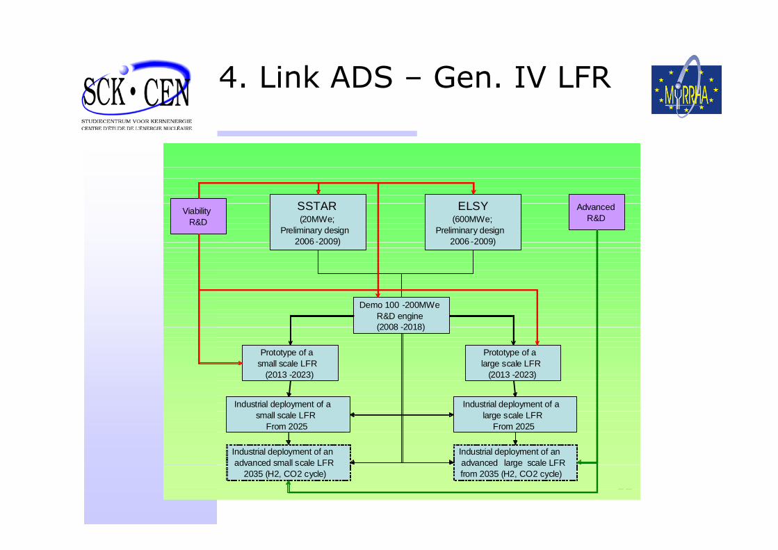
4. Link ADS – Gen. IV LFR
SSTAR (20MWe;
Preliminary design2006 -2009)
ELSY(600MWe;
Preliminary design2006 -2009)
Demo 100 -200MWe R&D engine(2008 -2018)
Industrial deployment of a small scale LFR
From 2025
Prototype of a small scale LFR
(2013 -2023)
Prototype of a large scale LFR
(2013 -2023)
ViabilityR&D
AdvancedR&D
Industrial deployment of alarge scale LFR
From 2025
Industrial deployment of an advanced small scale LFR
2035 (H2, CO2 cycle)
Industrial deployment of an advanced large scale LFRfrom 2035 (H2, CO2 cycle)
58
5-Well established and design driven support R&D Programme
• Pluri-annual R&D support programmeestablished around the MYRRHA project inside SCK•CEN
• A bilateral collaboration network of quality
• The support R&D programme enhanced thanks to EUROTRANS
59
5. The MYRRHA R&D Programme
• Since the beginning of the MYRRHA project, we decided to accompany the project by a comprehensive support R&D programme including:
Windowless spallation target thermal-hydraulic design. Vacuum Interface compatibility, LBE technology: Po migration, visibility under LBE through ultrasonic cameras, Material Corrosion & erosion and their mitigation,LBE conditioning and monitoring,Material embrittlement due to irradiation and LME,MOX fuel qualification under LBE and irradiation up to high targeted burn up (100 GWd/t) and high dpa (100) and also under representative transient conditions,Instrumentation development: O2-meters (< 200°C), HLM free surface monitoring, sub-criticality monitoring, ultrasonic visualisation Robotics : development of a robot arm to be deployed under LBE for testing and qualification
60
5. MYRRHA Collaboration Network (1/3)
• IBA, Belgium: cyclotron design and/or Intermediate energy section of the LINAC (normal conducting);
• ENEA, Italy: spallation source thermal-hydraulics design, core dynamics;
• UCL, Belgium: spallation source design water experiment, CFD modelling, Advanced CFD development;
• FZR, Germany: instrumentation for the spallation target;
• FZK, Germany: windowless spallation source testing with Pb-Bi in KALLA, Material Corrosion studies, Neutronics of sub-critical systems;
• NRG, The Netherlands: Spallation Source CFD modelling and system safety assessment;
61
5. MYRRHA Collaboration Network (2/3)
• CEA, France: subcritical core design, MUSE experiments;
• CNRS/IN2P3, France: LINAC development and components design, Windowless Spallation Target design, T91 structural material research, sub-critical core physics,
• PSI, Switzerland: basic spallation data, MEGAPIE;• IPUL, Latvia: windowless spallation source testing
with Hg,• Belgonucléaire, Belgium: MOX Fuel manufacturer
fuel pin and assembly design, fuel loading policy and fuel procurement;
• CIEMAT, Spain: Neutronic core design;• KTH, Sweden: development and validation on basis
of experimental results of adapted burn up codes for ADS,
• IPPE, Russia: design of the MYRRHA sub-critical reactor;
62
5. MYRRHA Collaboration Network (3/3)
• Suez-Tractebel, Belgium: confinement building and auxiliary systems, Safety analysis studies.
• OTL, UK: Remote Handling & Robotics design and development;
• USI_KU, Lithuania: development of US sensors operational under LBE and aggressive radiation environment, development of associated visualisation camera and signal treatment;
• AFCN and AVN, Belgium: Licensing authorities• JAEA, Japan : Material for fuel cladding, LBE
technology, ADS Design• Contacts that may lead to additional collaborations
exist with:ISTC: JINR-Dubna, Russia, YALINA-Minsk, Belarus (Through EUROTRANS)DoE and LANL; USACIAE, China
63
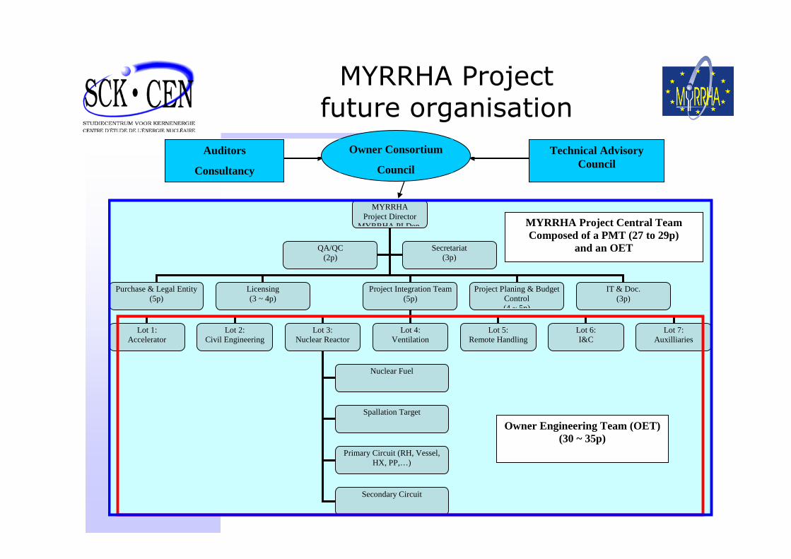
MYRRHA Projectfuture organisation
MYRRHA Project Director
MYRRHA PLDep
Purchase & Legal Entity (5p)
Licensing (3 ~ 4p)
Project Integration Team (5p)
QA/QC (2p)
Project Planing & Budget Control (4 ~ 5p)
Secretariat (3p)
IT & Doc. (3p)
Lot 1: Accelerator
Lot 2: Civil Engineering
Lot 3: Nuclear Reactor
Lot 4: Ventilation
Nuclear Fuel
Spallation Target
Primary Circuit (RH, Vessel, HX, PP,…)
Secondary Circuit
Lot 5: Remote Handling
Lot 6: I&C
Lot 7: Auxilliaries
MYRRHA Project Central Team Composed of a PMT (27 to 29p)
and an OET
Owner Engineering Team (OET) (30 ~ 35p)
Auditors
Consultancy
Owner Consortium
Council
Technical AdvisoryCouncil
64
Roadmap of an XT-ADSat Mol (I)
• End 2008 The conceptual design available. • Informal discussions with the safety authorities
submit end of 2008 Preliminary Decommissioning Plan (PDP) to the waste management authorities –ONDRAF/NIRAS.
• 2009 – 2013 to work in parallel on:2009 – 2011 : detailed engineering design2012 – 2013: Drafting of the technical specifications of the different lots, the publication of the call for tenders, and awarding of the manufacturing contracts2009 – 2011 : In parallel testing of innovative components (for the accelerator and for the reactor);2009 – 2013 : Licensing and permitting obtain the authorization of construction at the end of 2013
65
Roadmap of an XT-ADSat Mol (II)
• 2014 – 2016 construction of components and the civil engineering works on the Mol site.
• 2017 Assembling together the different components
• 2018 – 2019 commissioning (at progressive levels of power).
• 2020 MYRRHA/XT-ADS full Power operation
66
Summary of costs & contingencies:
• The total investment costs expressed in current value (2007) amounts to:
• 570 M€ without contingencies and 700 M€ with contingencies.
• In the 2007 MYRRHA project cost assessment, the project management costs are included.
• MYRRHA Project will be proposed as European open Research Facility for potential partners (Business plan 04.2007) will presented officially soon.
• First we are working for obtaining the Belgian support and commitment (Government, Industries, Universities)
67
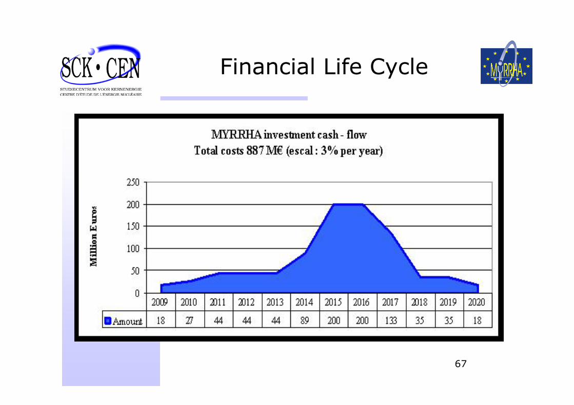
Financial Life Cycle
68
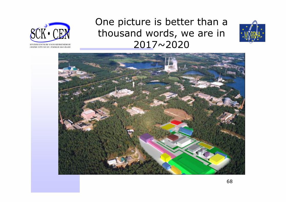
One picture is better than a thousand words, we are in
2017~2020