Embed Size (px)
Citation preview
From ‘potentially’ unsafe to unsafe by inadequate tube plugging
Modern urea plants are inspected after longer interval times due to improved inspection techniques, improved material qualities and/or risk based inspection philosophies. Inspections are generally a
combination of visual “corrosion” inspections combined with non destructive testing techniques like eddy current and/or ultrasonic techniques. Inspections are mainly focused on the critical equipment in
the high pressure synthesis section, where severe corrosion conditions prevail during normal operations. Based on the longer interval between inspections, it becomes necessary to plug heat
exchanger tubes which suffer from overall corrosion to prevent an in-service failure. This might be the case when the calculated corrosion rate and desired inspection interval results in insufficient wall
thickness. In this case, heat exchanger tube(s) need to be plugged preventively to avoid unsafe operations. Besides overall wall thickness decrease, which is typically found in high pressure strippers
and other high pressure heat exchangers, local defects may also make plugging necessary.
This paper describes the plugging philosophy adopted by Stamicarbon for plugging tubes in the critical HP heat exchangers. A proper plugging procedure, proper preparations and proper execution of the plugging are of paramount importance for safe operations. In this paper several plugging methods
utilized in urea plants with their respective advantages and disadvantages will be presented. Some of these methods will lead to unsafe situations, which will be demonstrated by some examples.
Joost Roes Sr. Mechanical Engineer, Stamicarbon
Introduction
rea Plant shutdowns are generally well planned events. Many activities are performed simultaneously, and
inspections together with maintenance activities play a key role during these shutdowns. Based on inspection results, sometimes repairs are necessary to ensure safe operations until the next planned shutdown. These repairs are often performed at the end of the shutdown where time constraints are evident. However, plugging of heat exchanger tubes in high pressure synthesis equipment of Urea plants should be done thoroughly with proper preparations in order to avoid “unsafe” operations. This paper will discuss a philosophy of tube plugging in HP urea heat exchangers. Some examples are
presented where plugging was done with inadequate attention to quality resulting in quite severe damages to the HP vessels. Tube to tubesheet welding High Pressure Strippers in Stamicarbon Urea Plants are placed vertically in the structure, and are designed in such a way that the heat exchanger tubes protrude through the top and bottom tubesheet. The protrusion varies between 8 to 10 mm in the bottom tubesheet and 20 mm in the top tubesheet to allow proper mounting of the liquid divider system. These protruding tube ends may be welded by automatic orbital gas tungsten arc welding or by manual GTAW welding. Both welding methods
U
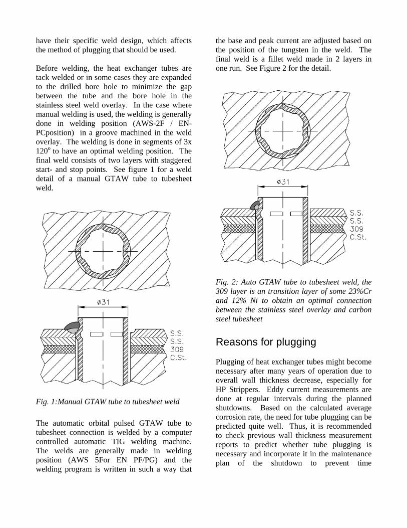
have their specific weld design, which affects the method of plugging that should be used. Before welding, the heat exchanger tubes are tack welded or in some cases they are expanded to the drilled bore hole to minimize the gap between the tube and the bore hole in the stainless steel weld overlay. In the case where manual welding is used, the welding is generally done in welding position (AWS-2F / EN-PCposition) in a groove machined in the weld overlay. The welding is done in segments of 3x 120o to have an optimal welding position. The final weld consists of two layers with staggered start- and stop points. See figure 1 for a weld detail of a manual GTAW tube to tubesheet weld.
Fig. 1:Manual GTAW tube to tubesheet weld The automatic orbital pulsed GTAW tube to tubesheet connection is welded by a computer controlled automatic TIG welding machine. The welds are generally made in welding position (AWS 5For EN PF/PG) and the welding program is written in such a way that
the base and peak current are adjusted based on the position of the tungsten in the weld. The final weld is a fillet weld made in 2 layers in one run. See Figure 2 for the detail.
Fig. 2: Auto GTAW tube to tubesheet weld, the 309 layer is an transition layer of some 23%Cr and 12% Ni to obtain an optimal connection between the stainless steel overlay and carbon steel tubesheet Reasons for plugging Plugging of heat exchanger tubes might become necessary after many years of operation due to overall wall thickness decrease, especially for HP Strippers. Eddy current measurements are done at regular intervals during the planned shutdowns. Based on the calculated average corrosion rate, the need for tube plugging can be predicted quite well. Thus, it is recommended to check previous wall thickness measurement reports to predict whether tube plugging is necessary and incorporate it in the maintenance plan of the shutdown to prevent time
constraints. Besides the general overall corrosion there are several reasons for tube plugging which cannot be predicted like:
1. Stress corrosion cracking (SCC) caused by chloride contamination.
2. Mechanical damage to tube protrusions by removal of internals for inspection.
3. Plugging of tube-area due to damage of the tubesheet (carbamate corrosion to carbon steel tubesheet).
Leak detection A leaking heat exchanger tube can be noticed in two ways.
1. By sudden tube rupture in case of overall wall thickness thinning.
2. By increasing conductivity of the steam (condensate) due to the presence of ammonia on the shell side of the vessel.
In case of the tube rupture, it is clear that the urea plant will shutdown automatically due to the release of urea, carbamate and/or ammonia and carbon dioxide. The complete contents of the synthesis section will be released via a rupture disc or safety provision. In the case of a small leak, the conductivity of the steam condensate will increase suddenly, due to the dissociation of the ammonium carbamate into it’s ionic species (NH4
+ and NH2COO- ) in the steam condensate which increases the conductivity of the steam condensate which is immediately noticed from the conductivity measurement. (normal conductivity values ranges typically between 15 to 25 microsiemens / meter). In case of a leaking tube to tubesheet weld, the leaking carbamate will dissociate into ammonia and carbon dioxide due to the pressure drop between tube-side and shell side. The ammonia as well as the carbon dioxide will find its way to the shell via the gap between the heat exchanger tube and tubesheet. For this reason, heat
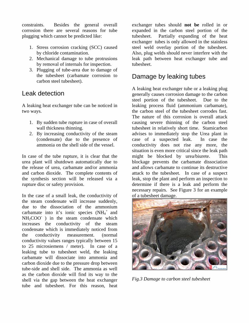
exchanger tubes should not be rolled in or expanded in the carbon steel portion of the tubesheet. Partially expanding of the heat exchanger tubes is only allowed in the stainless steel weld overlay portion of the tubesheet. Also, plug welds should never interfere with the leak path between heat exchanger tube and tubesheet. Damage by leaking tubes A leaking heat exchanger tube or a leaking plug generally causes corrosion damage to the carbon steel portion of the tubesheet. Due to the leaking process fluid (ammonium carbamate), the carbon steel of the tubesheet corrodes fast. The nature of this corrosion is overall attack causing severe thinning of the carbon steel tubesheet in relatively short time. Stamicarbon advises to immediately stop the Urea plant in case of a suspected leak. In case the conductivity does not rise any more, the situation is even more critical since the leak path might be blocked by urea/biurete. This blockage prevents the carbamate dissociation and allows carbamate to continue its destructive attack to the tubesheet. In case of a suspect leak, stop the plant and perform an inspection to determine if there is a leak and perform the necessary repairs. See Figure 3 for an example of a tubesheet damage.
Fig.3 Damage to carbon steel tubesheet
Inspection after suspected leak Before shutting down, the vessel which is causing the increase in conductivity should be identified. After shutting down the plant and cooling, the suspected vessel has to be opened at top and bottom side. An ammonia leak test is preferred to find the leaking tube. Often a bubble test with a water soap solution is used; although a water pressure test might be sufficient to find the leaking tube or tube to tubesheet weld. A helium leak test might be considered, however this method is not preferred since it is difficult to pinpoint the exact location of the leak. Normally, it is very hard to find the damage caused by the leakage. The inside of the vessel consists of stainless or duplex stainless steel which is resistant to the carbamate. Only at the leak spot there will be damage to the carbon steel tubesheet. This damage can be found by eddy current method. This method can also approximate the extent of the damage. After a proper assessment of the damage, the repairs options can be discussed. The repairs to the tube sheets have become more complicated nowadays. Due to the increasing size of the vessels, the materials selected for the carbon steel tubesheets have become high strength steels like SA508. Smaller or older vessels used more repair friendly materials for tubesheets (1.0482, 19Mn5). Several ways of Plugging The fastest, but also risky, way of tube plugging is the use of a flexible plug which is melted (with or without filler wire) to the existing protruding tube-end. When a heat exchanger tube is plugged in this way, the quality of the tube protrusion is extremely important. After many years of operation, the protruding tube ends show some cross cut end attack especially when BC.01 (316L UG) tube material is used. This corrosion makes it virtually impossible to
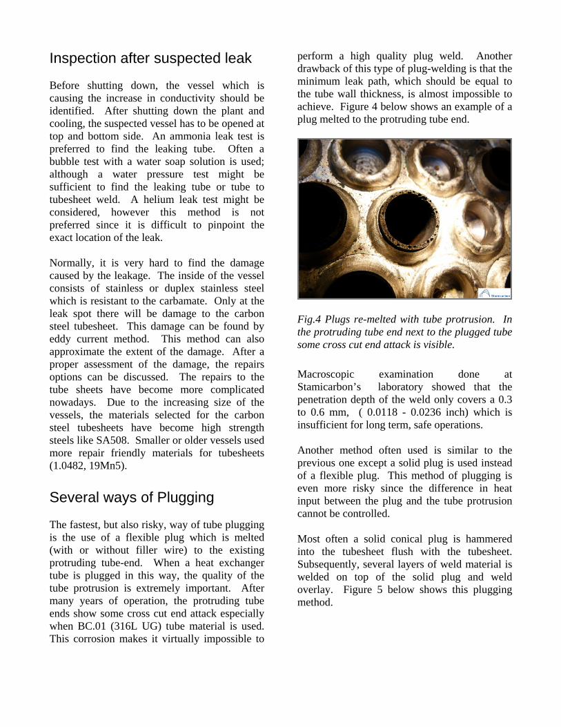
perform a high quality plug weld. Another drawback of this type of plug-welding is that the minimum leak path, which should be equal to the tube wall thickness, is almost impossible to achieve. Figure 4 below shows an example of a plug melted to the protruding tube end.
Fig.4 Plugs re-melted with tube protrusion. In the protruding tube end next to the plugged tube some cross cut end attack is visible. Macroscopic examination done at Stamicarbon’s laboratory showed that the penetration depth of the weld only covers a 0.3 to 0.6 mm, ( 0.0118 - 0.0236 inch) which is insufficient for long term, safe operations. Another method often used is similar to the previous one except a solid plug is used instead of a flexible plug. This method of plugging is even more risky since the difference in heat input between the plug and the tube protrusion cannot be controlled. Most often a solid conical plug is hammered into the tubesheet flush with the tubesheet. Subsequently, several layers of weld material is welded on top of the solid plug and weld overlay. Figure 5 below shows this plugging method.
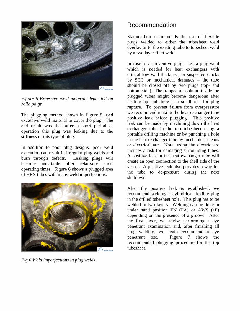
Figure 5:Excessive weld material deposited on solid plugs The plugging method shown in Figure 5 used excessive weld material to cover the plug. The end result was that after a short period of operation this plug was leaking due to the stiffness of this type of plug. In addition to poor plug designs, poor weld execution can result in irregular plug welds and burn through defects. Leaking plugs will become inevitable after relatively short operating times. Figure 6 shows a plugged area of HEX tubes with many weld imperfections.
Fig.6 Weld imperfections in plug welds
Recommendation Stamicarbon recommends the use of flexible plugs welded to either the tubesheet weld overlay or to the existing tube to tubesheet weld by a two layer fillet weld. In case of a preventive plug - i.e., a plug weld which is needed for heat exchangers with critical low wall thickness, or suspected cracks by SCC or mechanical damages – the tube should be closed off by two plugs (top- and bottom side). The trapped air column inside the plugged tubes might become dangerous after heating up and there is a small risk for plug rupture. To prevent failure from overpressure we recommend making the heat exchanger tube positive leak before plugging. This positive leak can be made by machining down the heat exchanger tube in the top tubesheet using a portable drilling machine or by punching a hole in the heat exchanger tube by mechanical means or electrical arc. Note: using the electric arc induces a risk for damaging surrounding tubes. A positive leak in the heat exchanger tube will create an open connection to the shell side of the vessel. A positive leak also provides a way for the tube to de-pressure during the next shutdown. After the positive leak is established, we recommend welding a cylindrical flexible plug in the drilled tubesheet hole. This plug has to be welded in two layers. Welding can be done in under hand position EN (PA) or AWS (1F) depending on the presence of a groove. After the first layer, we advise performing a dye penetrant examination and, after finishing all plug welding, we again recommend a dye penetrant test. Figure 7 shows the recommended plugging procedure for the top tubesheet.
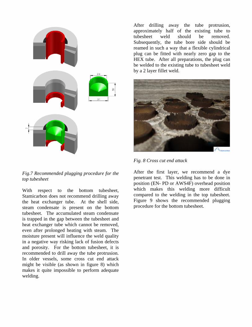
Fig.7 Recommended plugging procedure for the top tubesheet With respect to the bottom tubesheet, Stamicarbon does not recommend drilling away the heat exchanger tube. At the shell side, steam condensate is present on the bottom tubesheet. The accumulated steam condensate is trapped in the gap between the tubesheet and heat exchanger tube which cannot be removed, even after prolonged heating with steam. The moisture present will influence the weld quality in a negative way risking lack of fusion defects and porosity. For the bottom tubesheet, it is recommended to drill away the tube protrusion. In older vessels, some cross cut end attack might be visible (as shown in figure 8) which makes it quite impossible to perform adequate welding.
After drilling away the tube protrusion, approximately half of the existing tube to tubesheet weld should be removed. Subsequently, the tube bore side should be reamed in such a way that a flexible cylindrical plug can be fitted with nearly zero gap to the HEX tube. After all preparations, the plug can be welded to the existing tube to tubesheet weld by a 2 layer fillet weld.
Fig. 8 Cross cut end attack After the first layer, we recommend a dye penetrant test. This welding has to be done in position (EN- PD or AWS4F) overhead position which makes this welding more difficult compared to the welding in the top tubesheet. Figure 9 shows the recommended plugging procedure for the bottom tubesheet.
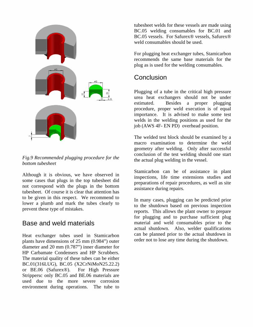
Fig.9 Recommended plugging procedure for the bottom tubesheet Although it is obvious, we have observed in some cases that plugs in the top tubesheet did not correspond with the plugs in the bottom tubesheet. Of course it is clear that attention has to be given in this respect. We recommend to lower a plumb and mark the tubes clearly to prevent these type of mistakes. Base and weld materials Heat exchanger tubes used in Stamicarbon plants have dimensions of 25 mm (0.984”) outer diameter and 20 mm (0.787”) inner diameter for HP Carbamate Condensers and HP Scrubbers. The material quality of these tubes can be either BC.01(316LUG), BC.05 (X2CrNiMoN25.22.2) or BE.06 (Safurex®). For High Pressure Strippersc only BC.05 and BE.06 materials are used due to the more severe corrosion environment during operations. The tube to
tubesheet welds for these vessels are made using BC.05 welding consumables for BC.01 and BC.05 vessels. For Safurex® vessels, Safurex® weld consumables should be used. For plugging heat exchanger tubes, Stamicarbon recommends the same base materials for the plug as is used for the welding consumables. Conclusion Plugging of a tube in the critical high pressure urea heat exchangers should not be under estimated. Besides a proper plugging procedure, proper weld execution is of equal importance. It is advised to make some test welds in the welding positions as used for the job (AWS 4F- EN PD) overhead position. The welded test block should be examined by a macro examination to determine the weld geometry after welding. Only after successful conclusion of the test welding should one start the actual plug welding in the vessel. Stamicarbon can be of assistance in plant inspections, life time extensions studies and preparations of repair procedures, as well as site assistance during repairs. In many cases, plugging can be predicted prior to the shutdown based on previous inspection reports. This allows the plant owner to prepare for plugging and to purchase sufficient plug material and weld consumables prior to the actual shutdown. Also, welder qualifications can be planned prior to the actual shutdown in order not to lose any time during the shutdown.
FINAL CONCLUSION: IN ALL CASES PLUGGING A HEAT EXCHANGER TUBE INTRODUCES A POTENTIONAL RISK FOR LEAKAGES. THEREFORE, IT IS OF PARAMOUNT IMPORTANCE TO PLAN AND TAKE NECESSARY PRECAUTIONS WHEN INSTALLING TUBE PLUGS TO ENSURE SAFE OPERATIONS.