Embed Size (px)
Citation preview
FROM SFM TO 3D PRINT: AUTOMATED WORKFLOW ADDRESSED TO
PRACTITIONER AIMED AT THE CONSERVATION AND RESTAURATION
L. Inzerillo a*, F. Di Paola a
a DARCH, Department of Architecture, Polytechnic School, 90128 Palermo, Italy –
[email protected], [email protected]
KEY WORDS: SfM, Image Based Modeling, Automation, Restauration, Conservation, 3D printing
ABSTRACT:
In In the last years there has been an increasing use of digital techniques for conservation and restoration purposes. Among these, a
very dominant rule is played by the use of digital photogrammetry packages (Agisoft Photoscan, 3D Zephir) which allow to obtain in
few steps 3D textured models of real objects. Combined with digital documentation technologies digital fabrication technologies can
be employed in a variety of ways to assist in heritage documentation, conservation and dissemination.
This paper will give to practitioners an overview on the state of the art available technologies and a feasible workflow for optimizing
point cloud and polygon mesh datasets for the purpose of fabrication using 3D printing. The goal is to give an important contribute to
confer an automation aspect at the whole processing. We tried to individuate a workflow that should be applicable to several types of
cases apart from small precautions. In our experimentation we used a DELTA WASP 2040 printer with PLA easyfil.
1. INTRODUCTION
Digital manufacturing techniques or 3D printing allow us, by
numerical control machines (CNC), to create physical objects
directly from 3D digital geometries bypassing the production and
interpretation of technical drawings. Until today, the latter
represented the only communication tool between two phases:
design and production; which have always been distinct and
never really integrated into one process.
Thanks to the development of new technologies that increase the
degree of accuracy and reduce production costs, digital
manufacturing is now successfully applied in many different
contexts.
In the field of conservation, diagnosis and restoration of Cultural
Heritage (CH) (Inzerillo, Dalli Cardillo 2013), several and
consolidated procedures have been started by museum
institutions, supervisors and specialized agencies that use
computerized and automated processes to enhance their
traditional research tools.
The use of 3D printing systems is now consolidated, specially, in
the field of 3D artworks reproduction for exhibitions in museum
itineraries or for reconstructions of missing parts, resulting from
destruction or damage (Alberghina, et al. 2016; Arbace, et al.
2012).
It is known that the traditional approach of producing rubber
molds for replication of plaster or resin copies requires a molding
procedure on the original work, which is, in fact, an invasive
operation that could cause irreversible damage.
Digital manufacturing is particularly effective and functional in
terms of flexibility, reversibility and non-invasibility (Lo Presti,
et al. 2011).
Indeed, when a practitioner starts to print the 3D model often
incurs in unpleasant inconveniences and this is aggravated if the
3D model has been carried out from SfM techniques. This is
because the SfM model is often jagged and requires more steps
* Corresponding author
of geometric elaboration. The goal of this paper is to design a
workflow aimed at define the whole process from the 3D SfM
model to the 3D print. It is known that not all the 3D models are
“printable”. The requirements of 3D models are many and we
will describe them in the paper. Some of them are related to the
shape and detail but, some other are more basic like the
triangulation, the closing, the shelling and the topologically
cleaning. So, not all 3D models are directly printable but may
require conversion, resampling, heavy edit. If the 3D model
author well knows all these conditions, can easily create his
model using strategies to create a printer friendly geometries. But
when the practitioner carries out the 3D model by a SfM
technique, there are more probabilities that it will be an
unprintable model. The printer cannot directly handle a 3D model
but needs clear instructions on how to print it.
The main requirements are, for example, the slice of the object
depending on the dimension of the print model; or the closing of
the object or the construction of a geometrical plan to support a
particular shape and create the stability to the physical printed
model (Neumüeller, et al. 2014).
There will always be unprintable models and unprintable
geometries! Particular attention is needed when there are
overhang or outstanding parts or steeps surfaces or undercuts.
Beyond that it is necessary to familiarize yourself with the 3D
machine temperature both of the wire and of the plant. The plastic
shrinks when cooling, curling or cracking the object. It should be
happened that during the printing the are some thickening of the
plastic material and this compromises the whole process.
Sometimes, the inexpensive printers are more efficient than the
sophisticated ones that requires more training and experience.
Obviously there are to consider some different material: ceramic,
metal and sintering, hybrid and even stone (to replicate shape and
material of a work art on the Cultural Heritage field) printers are
available on the market. The practitioner will choose the most
The International Archives of the Photogrammetry, Remote Sensing and Spatial Information Sciences, Volume XLII-2/W5, 2017 26th International CIPA Symposium 2017, 28 August–01 September 2017, Ottawa, Canada
This contribution has been peer-reviewed. doi:10.5194/isprs-archives-XLII-2-W5-375-2017 | © Authors 2017. CC BY 4.0 License.
375
suited to his needs. At the end, but not for importance, there is to
consider the maintenance (like the nozzle cleaning or some
misalignment of the mechanical arms) and small repairs of a 3D
printer.
Considering that nowadays, there are valid automated alternative
for the SfM process, like Autodesk 3D Catch or Recap and other
ones are going to be able on the web, if there is a clear
methodology to go through from the SfM model to the 3D
printing the practitioner is able to create a 3D printed model that
will realize his own design ideas.
In the history of manufacturing, subtractive methods have often
come first. The province of machining (generating exact shapes
with high precision) was generally a subtractive affair, from
filing and turning through milling and grinding.
Additive manufacturing’s earliest applications have been on the
toolroom end of the manufacturing spectrum. For example, rapid
prototyping was one of the earliest additive variants and its
mission was to reduce the lead time and cost of developing
prototypes of new parts and devices, which was earlier only done
with subtractive toolroom methods (typically slowly and
expensively). However, as the years go by and technology
continually advances, additive methods are moving ever further
into the production end of manufacturing. Parts that formerly
were the sole province of subtractive methods can now in some
cases be made more profitably via additive ones (Mendoza, et al.
2015; Taufik, et al. 2014).
However, the real integration of the newer additive technologies
into commercial production is essentially a matter of
complementing subtractive methods rather than displacing them
entirely. Predictions for the future of commercial manufacturing,
starting from today’s already- begun infancy period, are that
manufacturing firms will need to be flexible, ever-improving
users of all available technologies in order to remain competitive.
We started our journey into 3D printing a few months ago by
using a WASP 20/40, a Delta printer. We chosen a pre-assembled
3D printer, because assembling a 3D printer kit was certainly not
easy and the learning curve was definitely steep.
Before starting with our experience and the experimentation we
carried out, we report below some briefing aspect regarding the
3D printing.
2. 3D PRINTING
2.1 What to do to make the 3D printer work
As just said before, the 3D printing works with making a virtual
3D model of the object to print. The 3D model is for instance a
CAD (Computer Aided Design) file that is created using a 3D
modeling application through a 3D scanner or SfM techniques.
The 3D survey techniques, those image-based and range-based
ones, are focused to carry out the exactly copy of an existing
object. When the 3D model is carried out, is necessary to make
another step of working before it is ready to be 3D printed.
You have to adjust the 3D model into hundreds or thousands of
horizontal layers and needs to be done with software. This is the
slicing phase.
Each 3D printer needs different source to make the slicing steps.
Sometimes a 3D model can be sliced from within a 3D modeling
software application. It is also possible that you are forced to use
a certain slicing tool for a certain 3D printer. At the end of this
process the model is ready to be 3D printed. The connection
between the ready model and the printer is available through
USB, SD or wifi. Sometimes the wifi connection does not have a
strong signal and you need to update the 3D sliced model in the
SD card. Some 3D printers do not have the USB output, but work
with the wifi connection or SD card but, some other printers have
the USB output but not the wifi connection. It really depends on
what brand and type 3D Printer you have. When a file is uploaded
in a 3D printer, the object is ready to be 3D printed layer by layer.
The 3D printer reads every slice (2D image) and creates a three
dimensional object.
(https://3dprinting.com/what-is-3d-printing/).
Therefore, after all this, it is clear that you need to know your 3D
printer and understand how to create the 3D model. Even before
you create your 3D model you must know the strengths and
weaknesses of your 3Dprinter. Then, you chose the 3D acquiring
technology and finally make the 3D printing.
Let's take a quick look at the different types of 3Dprinting.
2.2 Different types of 3D printing technologies
Nowadays exist different types of 3D printing technologies. The
most diffused one is the one that use the Additive Manufacturing
(AM) methods. The 3D printers that work with the AM method
not use the same technology. The technology changes according
the way layers are built to create the final object.
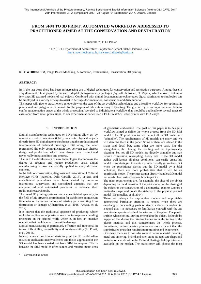
The American Society for Testing and Materials (ASTM) group
“ASTM F42 – Additive Manufacturing”, developed a set of
standards that classify the Additive Manufacturing processes into
7 categories according to Standard Terminology for Additive
Manufacturing Technologies (Fig. 1). Additive Manufacturing
Technologies (Gibson, et al. 2014; Excell, 2013, Kodama,
1981a).
The seven processes are classified as follow:
1. Vat Photopolymerisation
a. Stereolithography (SLA)
b. Digital Light Processing (DLP)
c. Continuous Liquid Interface
Production (CLIP)
2. Material Jetting
3. Binder Jetting
4. Material Extrusion
a. Fused Deposition Modeling (FDM)
b. Fused Filament Fabrication (FFF)
5. Powder Bed Fusion
a. Selective laser sintering (SLS)
6. Sheet Lamination
7. Directed Energy Deposition
Figure 1. Different types of 3D digital
Manufacturing technologies
The International Archives of the Photogrammetry, Remote Sensing and Spatial Information Sciences, Volume XLII-2/W5, 2017 26th International CIPA Symposium 2017, 28 August–01 September 2017, Ottawa, Canada
This contribution has been peer-reviewed. doi:10.5194/isprs-archives-XLII-2-W5-375-2017 | © Authors 2017. CC BY 4.0 License.
376
1) The Vat Photopolymerisation method provides to have a
container filled with photopolymer resin which is then hardened
with a UV light source. Within the Vat Photopolymerisation
method, there are the Stereolithography (SLA), that is the most
commonly used, the Digital Light Processing (DLP), that makes
use of light and photosensitive polymers and the Continuous
Liquid Interface Production (CLIP), that is ultrafast.
2) In Material Jetting, material is applied in droplets through a
small diameter nozzle, similar to the way a common inkjet paper
printer works, but it is applied layer-by-layer to a build platform
making a 3D object and then hardened by UV light.
3) With Binder Jetting two materials are used: powder base
material and a liquid binder. In the build chamber, powder is
spread in equal layers and binder is applied through jet nozzles
that “glue” the powder particles in the shape of a programmed
3D object.
4) The Material Extrusion process uses a method of rapid
prototyping. Within it there are two different technology: the
Fused Deposition Modeling (FDM) and the Fused Filament
Fabrication (FFF). The first one is the one used by WASP
DELTA 20/40 (Kodama, 1981b).
5) Powder Bed Fusion /Selective Laser Sintering (SLS) uses a
high power laser to fuse small particles of plastic, metal, ceramic
or glass powders into a mass that has the desired three
dimensional shape.
6) Sheet Lamination involves material in sheets which is bound
together with external force. Sheets can be metal, paper or a form
of polymer. Metal sheets are welded together by ultrasonic
welding in layers and then CNC milled into a proper shape.
7) Directed Energy Deposition is mostly used in the high-tech
metal industry and in rapid manufacturing applications. The 3D
printing apparatus is usually attached to a multi-axis robotic arm
and consists of a nozzle that deposits metal powder or wire on a
surface and an energy source (laser, electron beam or plasma arc)
that melts it, forming a solid object.
2.3 DELTA 3D printers
Delta 3D printers use the FFF / FDM technologies depending on
the coordinate systems and the mechanical arrangements.
Some manufacturers choose mechanical simplicity at the expense
of moving the build platform while others attempt to increase
extruder head speed by using fixed motors and complex belt
actuation. The most popular mechanical arrangements for FFF /
FDM 3D printers are:
● Cartesian-XY-head
● Cartesian-XZ-head
● Delta
● CoreXY
● Polar
● Scara (robot arm)
As said before we used the WASP DELTA 20/40.
Delta 3D printers also work within the Cartesian plane, however
the setup of the frame is totally different. They are called Delta
because the extruder head is suspended by three arms in a
triangular configuration. Besides that they have a circular print
bed. In Delta 3D printer the moving parts are lightweight and,
therefore, limit the inertia. That results is a faster printing with
greater accuracy.
3. WORKFLOW
3.1 FDM printing pipeline
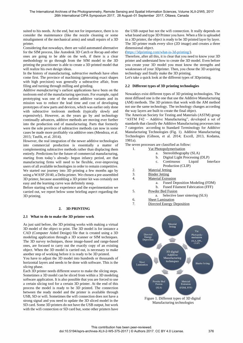
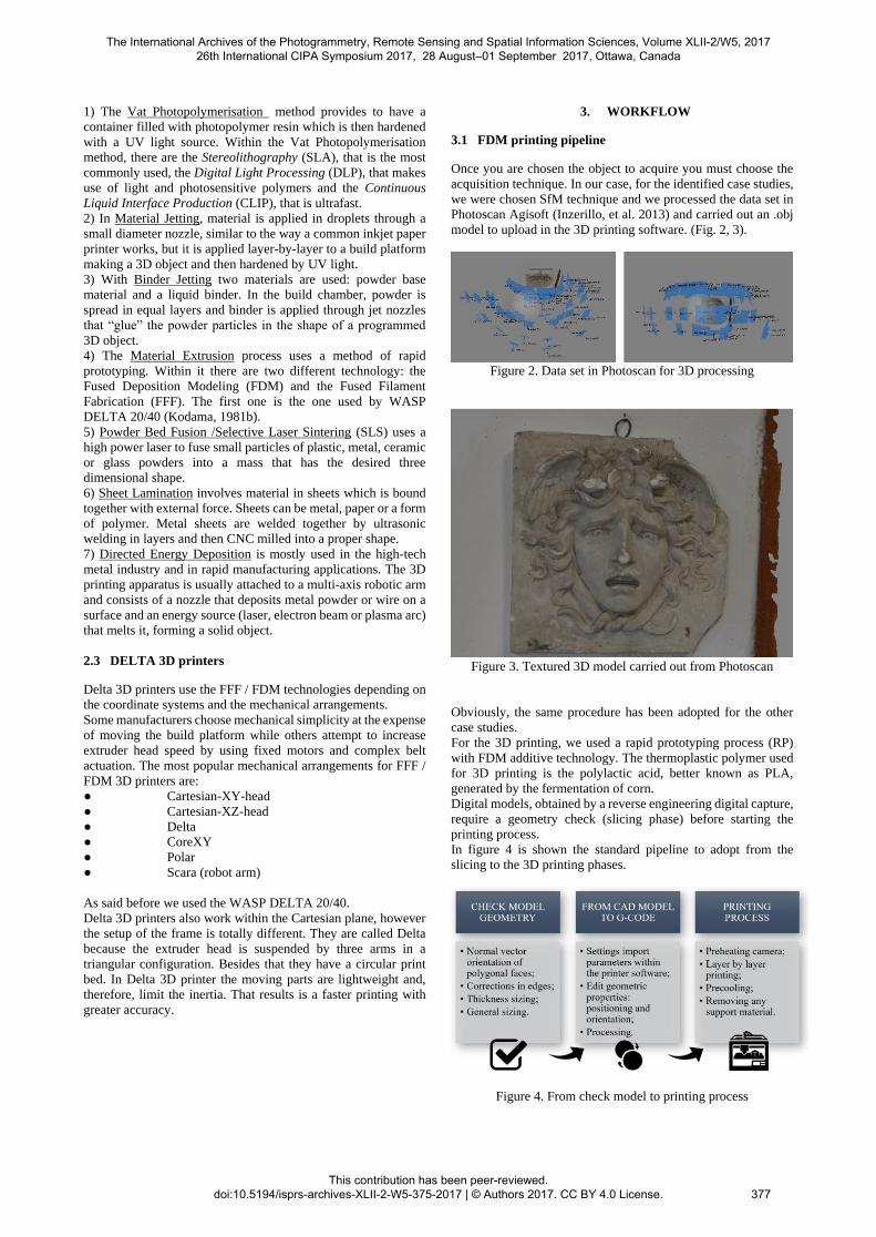
Once you are chosen the object to acquire you must choose the
acquisition technique. In our case, for the identified case studies,
we were chosen SfM technique and we processed the data set in
Photoscan Agisoft (Inzerillo, et al. 2013) and carried out an .obj
model to upload in the 3D printing software. (Fig. 2, 3).
Figure 2. Data set in Photoscan for 3D processing
Figure 3. Textured 3D model carried out from Photoscan
Obviously, the same procedure has been adopted for the other
case studies.
For the 3D printing, we used a rapid prototyping process (RP)
with FDM additive technology. The thermoplastic polymer used
for 3D printing is the polylactic acid, better known as PLA,
generated by the fermentation of corn.
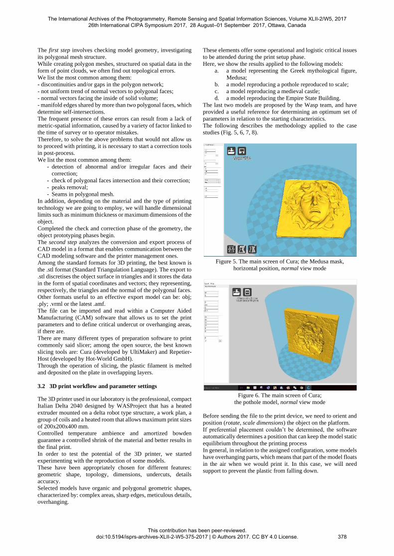
Digital models, obtained by a reverse engineering digital capture,
require a geometry check (slicing phase) before starting the
printing process.
In figure 4 is shown the standard pipeline to adopt from the
slicing to the 3D printing phases.
Figure 4. From check model to printing process
The International Archives of the Photogrammetry, Remote Sensing and Spatial Information Sciences, Volume XLII-2/W5, 2017 26th International CIPA Symposium 2017, 28 August–01 September 2017, Ottawa, Canada
This contribution has been peer-reviewed. doi:10.5194/isprs-archives-XLII-2-W5-375-2017 | © Authors 2017. CC BY 4.0 License.
377
The first step involves checking model geometry, investigating
its polygonal mesh structure.
While creating polygon meshes, structured on spatial data in the
form of point clouds, we often find out topological errors.
We list the most common among them:
- discontinuities and/or gaps in the polygon network;
- not uniform trend of normal vectors to polygonal faces;
- normal vectors facing the inside of solid volume;
- manifold edges shared by more than two polygonal faces, which
determine self-intersections.
The frequent presence of these errors can result from a lack of
metric-spatial information, caused by a variety of factor linked to
the time of survey or to operator mistakes.
Therefore, to solve the above problems that would not allow us
to proceed with printing, it is necessary to start a correction tools
in post-process.
We list the most common among them:
- detection of abnormal and/or irregular faces and their
correction;
- check of polygonal faces intersection and their correction;
- peaks removal;
- Seams in polygonal mesh.
In addition, depending on the material and the type of printing
technology we are going to employ, we will handle dimensional
limits such as minimum thickness or maximum dimensions of the
object.
Completed the check and correction phase of the geometry, the
object prototyping phases begin.
The second step analyzes the conversion and export process of
CAD model in a format that enables communication between the
CAD modeling software and the printer management ones.
Among the standard formats for 3D printing, the best known is
the .stl format (Standard Triangulation Language). The export to
.stl discretises the object surface in triangles and it stores the data
in the form of spatial coordinates and vectors; they representing,
respectively, the triangles and the normal of the polygonal faces.
Other formats useful to an effective export model can be: obj;
.ply; .vrml or the latest .amf.
The file can be imported and read within a Computer Aided
Manufacturing (CAM) software that allows us to set the print
parameters and to define critical undercut or overhanging areas,
if there are.
There are many different types of preparation software to print
commonly said slicer; among the open source, the best known
slicing tools are: Cura (developed by UltiMaker) and Repetier-
Host (developed by Hot-World GmbH).
Through the operation of slicing, the plastic filament is melted
and deposited on the plate in overlapping layers.
3.2 3D print workflow and parameter settings
The 3D printer used in our laboratory is the professional, compact
Italian Delta 2040 designed by WASProject that has a heated
extruder mounted on a delta robot type structure, a work plan, a
group of coils and a heated room that allows maximum print sizes
of 200x200x400 mm.
Controlled temperature ambience and amortized bowden
guarantee a controlled shrink of the material and better results in
the final print.
In order to test the potential of the 3D printer, we started
experimenting with the reproduction of some models.
These have been appropriately chosen for different features:
geometric shape, topology, dimensions, undercuts, details
accuracy.
Selected models have organic and polygonal geometric shapes,
characterized by: complex areas, sharp edges, meticulous details,
overhanging.
These elements offer some operational and logistic critical issues
to be attended during the print setup phase.
Here, we show the results applied to the following models:
a. a model representing the Greek mythological figure,
Medusa;
b. a model reproducing a pothole reproduced to scale;
c. a model reproducing a medieval castle;
d. a model reproducing the Empire State Building.
The last two models are proposed by the Wasp team, and have
provided a useful reference for determining an optimum set of
parameters in relation to the starting characteristics.
The following describes the methodology applied to the case
studies (Fig. 5, 6, 7, 8).
Figure 5. The main screen of Cura; the Medusa mask,
horizontal position, normal view mode
Figure 6. The main screen of Cura;
the pothole model, normal view mode
Before sending the file to the print device, we need to orient and
position (rotate, scale dimensions) the object on the platform.
If preferential placement couldn’t be determined, the software
automatically determines a position that can keep the model static
equilibrium throughout the printing process
In general, in relation to the assigned configuration, some models
have overhanging parts, which means that part of the model floats
in the air when we would print it. In this case, we will need
support to prevent the plastic from falling down.
The International Archives of the Photogrammetry, Remote Sensing and Spatial Information Sciences, Volume XLII-2/W5, 2017 26th International CIPA Symposium 2017, 28 August–01 September 2017, Ottawa, Canada
This contribution has been peer-reviewed. doi:10.5194/isprs-archives-XLII-2-W5-375-2017 | © Authors 2017. CC BY 4.0 License.
378
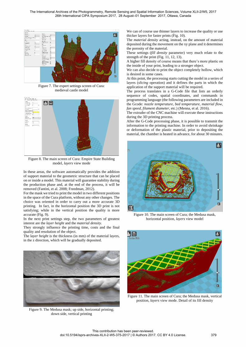
Figure 7. The expert settings screen of Cura:
medieval castle model
Figure 8. The main screen of Cura: Empire State Building
model, layers view mode
In these areas, the software automatically provides the addition
of support material to the geometric structure that can be placed
on or inside a model. This material will guarantee stability during
the production phase and, at the end of the process, it will be
removed (Fantini, et al. 2008; Freedman, 2012).
For the mask we tried to print the model in two different positions
in the space of the Cura platform, without any other changes. The
choice was oriented in order to carry out a more accurate 3D
printing. In fact, in the horizontal position the 3D print is not
satisfying; while in the vertical position the quality is more
accurate (Fig. 9).
In the next print settings step, the two parameters of greatest
interest are the layer height and the material density.
They strongly influence the printing time, costs and the final
quality and resolution of the object.
The layer height is the thickness (in mm) of the material layers,
in the z direction, which will be gradually deposited.
Figure 9. The Medusa mask; up side, horizontal printing;
down side, vertical printing
We can of course use thinner layers to increase the quality or use
thicker layers for faster prints (Fig. 10).
The material density acting, instead, on the amount of material
deposited during the movement on the xy plane and it determines
the porosity of the material.
These settings (fill density parameter) very much relate to the
strength of the print (Fig. 11, 12, 13).
A higher fill density of course means that there’s more plastic on
the inside of your print, leading to a stronger object.
We can also decide to print the object completely hollow, which
is desired in some cases.
At this point, the processing starts cutting the model in a series of
layers (slicing operation) and it defines the parts in which the
application of the support material will be required.
The process translates in a G-Code file that lists an orderly
sequence of codes, spatial coordinates, and commands in
programming language (the following parameters are included in
the Gcode: nozzle temperature, bed temperature, material flow,
fan speed, filament diameter, etc.) (Menna, et al. 2016).
The extruder of the CNC machine will execute these instructions
during the 3D printing process.
After the G-Code processing phase, it is possible to transmit the
information to the printing machine. In order to avoid shrinkage
or deformation of the plastic material, prior to depositing the
material, the chamber is heated in advance, for about 30 minutes.
Figure 10. The main screen of Cura; the Medusa mask,
horizontal position, layers view model
Figure 11. The main screen of Cura; the Medusa mask, vertical
position, layers view mode. Detail of its fill density
The International Archives of the Photogrammetry, Remote Sensing and Spatial Information Sciences, Volume XLII-2/W5, 2017 26th International CIPA Symposium 2017, 28 August–01 September 2017, Ottawa, Canada
This contribution has been peer-reviewed. doi:10.5194/isprs-archives-XLII-2-W5-375-2017 | © Authors 2017. CC BY 4.0 License.
379
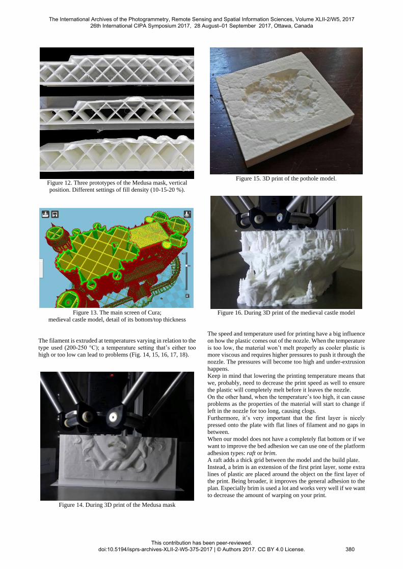
Figure 12. Three prototypes of the Medusa mask, vertical
position. Different settings of fill density (10-15-20 %).
Figure 13. The main screen of Cura;
medieval castle model, detail of its bottom/top thickness
The filament is extruded at temperatures varying in relation to the
type used (200-250 °C); a temperature setting that’s either too
high or too low can lead to problems (Fig. 14, 15, 16, 17, 18).
Figure 14. During 3D print of the Medusa mask
Figure 15. 3D print of the pothole model.
Figure 16. During 3D print of the medieval castle model
The speed and temperature used for printing have a big influence
on how the plastic comes out of the nozzle. When the temperature
is too low, the material won’t melt properly as cooler plastic is
more viscous and requires higher pressures to push it through the
nozzle. The pressures will become too high and under-extrusion
happens.
Keep in mind that lowering the printing temperature means that
we, probably, need to decrease the print speed as well to ensure
the plastic will completely melt before it leaves the nozzle.
On the other hand, when the temperature’s too high, it can cause
problems as the properties of the material will start to change if
left in the nozzle for too long, causing clogs.
Furthermore, it’s very important that the first layer is nicely
pressed onto the plate with flat lines of filament and no gaps in
between.
When our model does not have a completely flat bottom or if we
want to improve the bed adhesion we can use one of the platform
adhesion types: raft or brim.
A raft adds a thick grid between the model and the build plate.
Instead, a brim is an extension of the first print layer, some extra
lines of plastic are placed around the object on the first layer of
the print. Being broader, it improves the general adhesion to the
plan. Especially brim is used a lot and works very well if we want
to decrease the amount of warping on your print.
The International Archives of the Photogrammetry, Remote Sensing and Spatial Information Sciences, Volume XLII-2/W5, 2017 26th International CIPA Symposium 2017, 28 August–01 September 2017, Ottawa, Canada
This contribution has been peer-reviewed. doi:10.5194/isprs-archives-XLII-2-W5-375-2017 | © Authors 2017. CC BY 4.0 License.
380
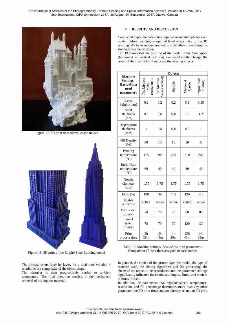
Figure 17. 3D print of medieval castle model
Figure 18. 3D print of the Empire State Building model
The process prints layer by layer, for a total time variable in
relation to the complexity of the object shape.
The chamber is then progressively cooled to ambient
temperature. The final operation consists in the mechanical
removal of the support material.
4. RESULTS AND DISCUSSION
Conducted experimentation has required many attempts for each
model, before reaching an optimal level of accuracy of the 3D
printing. We have encountered many difficulties in searching for
standard parameterization.
Tab 19 shows that the position of the model in the Cura space
(horizontal or vertical position) can significantly change the
result of the final 3Dprint reducing the aliasing effects.
Machine
Settings_
Basic/Adva
nced
parameters
Objects
The
Med
usa
Mas
k
(hori
zonta
l)
T
he
Med
usa
Mas
k (
ver
tica
l)
Poth
ole
Med
ieval
Cas
tle
Em
pir
e S
tate
Buil
din
g
Layer
height (mm) 0,2 0,2 0,2 0,2 0,15
Shell
thickness
(mm)
0,8 0,8 0,8 1,2 1,2
Top/bottom
thickness
(mm)
1 0,8 0,8 0,8 1
Fill Density
(%) 20 10 10 10 5
Printing
temperature
(°C)
175 200 200 210 200
Build Plate
temperature
(°C)
60 40 40 40 40
Nozzle
diameter
(mm)
1,75 1,75 1,75 1,75 1,75
Flow (%) 100 105 105 120 110
Enable
retraction active active active active active
Print speed
(mm/s) 70 70 70 80 80
Travel
speed
(mm/s)
70 70 70 120 120
process time
3h
39m
10h
45m
4h
39m
25h
40m
14h
25m
Table 19. Machine settings, Basic/Advanced parameters.
Comparison of the values assigned to case studies
In general, the choice of the printer type, the model, the type of
material used, the editing algorithms and file processing, the
shape of the object to be reproduced and the parameter settings
significantly influence the results and impose limits and choices
at times, forced.
In addition, the parameters that regulate speed, temperature,
resolution, and fill percentage determine, more than any other
parameter, the 3D print times and are directly related to 3D print
The International Archives of the Photogrammetry, Remote Sensing and Spatial Information Sciences, Volume XLII-2/W5, 2017 26th International CIPA Symposium 2017, 28 August–01 September 2017, Ottawa, Canada
This contribution has been peer-reviewed. doi:10.5194/isprs-archives-XLII-2-W5-375-2017 | © Authors 2017. CC BY 4.0 License.
381
accuracy. A proper balance between temperature and speed can
avoid incurring frequent errors such as: the corners deformation
(warping) due to shrinkage of the material; the sub-extrusion
phenomena, perforated surfaces, etc.
It is very important to control the printing of the first layer. You
must check the quality and adhesion of the first layer of melted
material on the printing plate. Any errors, could be due to: nozzle
distance from the plate; dish level; extruder and plate
temperatures. It is possible to intervene on these values on the
device display directly (Lu, et al. 2014).
CONCLUSIONS
In this paper, we demonstrated that there is a workflow that the
practitioner can use to have a friendly approach with its first
printing. Nevertheless, it is necessary to have a considerable
confidence with own printer to have the best result.
The automation of the 3D printing is going to be realized, but it
will be necessary that this necessity will become a necessity of
the building printer industry. It depend on the commercial
development of the international financial market.
It is predicted by some additive manufacturing advocates that this
technological development will change the nature of commerce,
because end users will be able to do much of their own
manufacturing rather than engaging in trade to buy products from
other people and corporations (Bird, 2012).
3D printers capable of outputting in colour and multiple materials
already exist and will continue to improve to a point where
functional products will be able to be output. With effects on
energy use, waste reduction, customization, product availability,
medicine, art, construction and sciences, 3D printing will change
the manufacturing world as we know it.
REFERENCES
Alberghina, M., Alberghina, F., Allegra, D., Di Paola, F.,
Maniscalco, L., Milazzo, G., et al., 2016. Integrated three-
dimensional models for noninvasive monitoring and valorization
of the Morgantina silver treasure (Sicily). In Journal of
Electronic Imaging (JEI), 26 (1), 1-14.
Arbace, L. et al., 2012. Innovative uses of 3D digital technologies
to assist the restoration of a fragmented terracotta statue, Journal
of Cultural Heritage, vol. 14 (4)
http://dx.doi.org/10.1016/j.culher.2012.06.008.
Bird, J., 2012. Exploring the 3D printing opportunity. In The
Financial Times. Retrieved 2012-08-30.
Excell, J., 2013. The rise of additive manufacturing. In The
Engineer, Retrieved 2013-10-30.
Fantini, M., De Crescenzio, F., Persiani, F., Benazzi, S.,
Gruppioni, G., 2008. 3D restitution, restoration and prototyping
of a medieval damaged skull. In Rapid Prototyping Journal 14,
pp. 318–324.
Freedman, D.H., 2012. Layer By Layer. In Technology Review,
115 (1): 50–53.
Gibson, I., Rosen, D., Stucker, B., 2014. 3D Printing, Rapid
Prototyping, and Direct Digital Manufacturing, Springer,
ISBN: 978-1-4939-2112-6 (Print) 978-1-4939-2113-3.
Inzerillo, L., Dalli Cardillo, G. (2013) Architectural Library. The
Dioscuri Temple in Agrigento. In 21st International Conference
in Central Europe on Computer Graphics, Visualization and
Computer Vision, WSCG 2013, pp. 33-36
Inzerillo, L., Santagati, C., Di Paola, F., 2013. Image-based
modeling techniques for architectural heritage 3D digitalization:
limits and potentialities, in International Archives of the
Photogrammetry, Remote Sensing and Spatial Information
Sciences, XL-5(W2): pp. 550-560.
Kodama, H., 1981a. A Scheme for Three-Dimensional Display
by Automatic Fabrication of Three-Dimensional Model. In
IEICE Transactions on Electronics, Japanese Edition, vol. J64-
C, No. 4, pp. 237–41.
Kodama, H., 1981b. Automatic method for fabricating a three-
dimensional plastic model with photo-hardening polymer.
Review of Scientific Instruments, Vol. 52, No. 11, pp. 1770–73.
Lo Presti, S., Di Paola, F., Mineo, S., 2011. Artificial stone in
architecture: new techniques of intervention in the Utveggio
Castle in Palermo, in Conservation Science in Cultural Heritage,
Issue n. 11, pp. 195-217, DOI: 10.6092/ISSN.1973-9494/2698.
Lu, L., Sharf, A., Zhao, H., Wei, Y., Fan, Q., Chen, X., Savoye,
Y., Tu, C., Cohen-Or, D. and Chen, B., 2014. Build-to-last:
Strength to weight 3D printed objects. In ACM Transactions on
Graphics (Proc. SIGGRAPH), 33, 4, August, 97:1– 97:10.
Mendoza, H.R., 2015. Alain Le Méhauté, The Man Who
Submitted Patent for SLA 3D Printing Before Chuck Hull.
https://3dprint.com/
Menna, F., Nocerino, E., Remondino, F., Dellepiane, M.,
Callieri, R., Scopigno, R., 2016. 3D digitization of an heritage
masterpiece - A critical analysis on quality assessment. in
International Archives of the Photogrammetry, Remote Sensing
and Spatial Information Sciences, Volume XLI-B5, 2016, XXIII
ISPRS Congress, (12–19 July 2016), Prague, Czech Republic.
Neumüeller, M., Reichinger, A., Rist, F., Kern, C., 2014. 3D
printing for cultural heritage: Preservation, accessibility, research
and education. In 3D Research Challenges in Cultural Heritage,
Ioannides M., Quak E., (Eds.), vol. 8355 of Lecture Notes in
Computer Science. Springer Berlin Heidelberg, 2014, pp. 119–
134.
Taufik, M., Jain, P.K., 2014. Role of build orientation in layered
manufacturing: a review. International Journal of Manufacturing
Technology and Management. 27 (1/2/3): 47–73.
DOI:10.1504/IJMTM.2013.058637.
The International Archives of the Photogrammetry, Remote Sensing and Spatial Information Sciences, Volume XLII-2/W5, 2017 26th International CIPA Symposium 2017, 28 August–01 September 2017, Ottawa, Canada
This contribution has been peer-reviewed. doi:10.5194/isprs-archives-XLII-2-W5-375-2017 | © Authors 2017. CC BY 4.0 License.
382