Embed Size (px)
Citation preview
VOLUME 72 NO.9/10 SEPTEMBER/OCTOBER 2019
www.bis-space.com
ISSN 0007-084X PUBLICATION DATE: 3 JANUARY 2020
Journal of the British Interplanetary Society
BIS SPACE Project special issue
FOREWORD TO THIS SPECIAL EDITION Richard J. Soilleux
FROM THE BRICK MOON TO ISLAND ONE: Space Habitats in Science Fiction Before O’Neill’s High Frontier Stephen Baxter
THE AVALON ORBITAL SETTLEMENT Stephen D. Gunn & Richard J. Soilleux
A RATIONALE FOR DEVELOPING AN ORBITAL MATERIALS PROCESSING AND MANUFACTURING COMPLEX (OMPMC) Utilizing Extra-terrestrial Materials Stephen D. Gunn & Richard J. Soilleux
THE OPTIMUM LOCATION FOR AN ORBITAL MATERIALS PROCESSING AND MANUFACTURING COMPLEX (OMPMC) Utilizing Extra-terrestrial Materials Stephen D. Gunn & Richard J. Soilleux
AVALON: A Tour of the Settlement Stephen Baxter
AVALON: The Governance of a Company Town in Space Stephen Baxter and Adam D.A. Manning
Subscriber copy

Rachel Armstrong, Newcastle University, UKPeter Bainum, Howard University, USAStephen Baxter, Science & Science Fiction Writer, UKJames Benford, Microwave Sciences, California, USAJames Biggs, The University of Strathclyde, UKAnu Bowman, Foundation for Enterprise Development, California, USAGerald Cleaver, Baylor University, USA Charles Cockell, University of Edinburgh, UKIan A. Crawford, Birkbeck College London, UKAdam Crowl, Icarus Interstellar, AustraliaEric W. Davis, Institute for Advanced Studies at Austin, USAKathryn Denning, York University, Toronto, CanadaMartyn Fogg, Probability Research Group, UKRaghavan Gopalaswami, Aerospace Researcher, IndiaLamartine Guimarães, Institute for Advanced Studies, BrazilMark Hempsell, Hempsell Astronautics Ltd, UKTakuto Ishimatsu, Massachusetts Institute of Technology, USALes Johnson, Marshall Space Flight Center, USATerry Kammash, University of Michigan, USAKelvin F. Long, Initiative for Interstellar StudiesInoue Makoto, Institute of Astronomy & Astrophysics Academia Sinica, TaiwanGregory L. Matloff, City University New York, USAKoichi Mori, Nagoya University, JapanRichard Obousy, Richard Obousy Consulting LLC, USARobert Parkinson, BIS, Aylesbury, UKGeorge Schmidt, NASA John H Glenn Research Center, Ohio, USAPaul Schuch, The SETI League Inc, USATabitha Smith, Bifrost, USAAndreas Tziolas, Variance Dynamical Corporation, USAChris Welch, The International Space University, Strasbourg, FranceFriedwardt Winterberg, University of Nevada, Reno, USA
JBIS welcomes the submission of technical papers for publication dealing with technical reviews, research, technology and engineering in astronautics and related fields.
Text should be:■ As concise as the content allows – typically 5,000
to 6,000 words. Shorter papers (Technical Notes) will also be considered; longer papers will only be considered in exceptional circumstances – for example, in the case of a major subject review.
■ Source references should be inserted in the text in square brackets – [1] – and then listed at the end of the paper.
■ Illustration references should be cited in numerical order in the text; those not cited in the text risk omission.
■ Captions must be labelled with their Fig. number and should be as short as possible.
Illustrations should be:■ Colour or mono, but should be as close to print
resolution (300 dpi) as possible. Poor-quality illustrations may compromise the acceptance of paper for publication. Images embedded in Word documents may be acceptable, but JBIS reserves the right to request separate higher-resolution image files from the author prior to publication.
■ Responsibility for copyright clearance of images rests entirely with the author.
Submission of papers■ Papers for consideration should be sent by
email to [email protected] as both a Word document and as a Word PDF file (in order to check for font anomalies), together with any separate image files.
■ If a paper is accepted for publication, the author will be asked to sign a License to Publish form. This can be downloaded at www.bis-space.com/wp-content/uploads/2012/08/WebsiteLicense.pdf.
■ Authors will receive a complimentary copy of the issue in which their paper appears.
We respectfully ask authors to adhere to these guidelines. Failure to do so will result in the delay of acceptable papers for publication.
Our full Guidelines for Authors can be downloaded from www.bis-space.com
Editor Roger Longstaff Deputy Editor Duncan Law-Green Associate Editors Stephen Ashworth, Keith Cooper, Stephen Gamble, Paul Gilster, Rob Swinney, Production MP3 Media Promotion Gill Norman JBIS Office British Interplanetary Society, Arthur C. Clarke House, 27-29 South Lambeth Road, London, SW8 1SZ, United Kingdom tel +44 (0)20 7735 3160 email [email protected] www.bis-space.com
DISTRIBUTION JBIS is distributed worldwide by mail and may be received by annual subscription or purchase of single copies. It is available through membership of the British Interplanetary Society at much reduced rates. Subscription details for members, non-members and libraries are available from the above address.
JBIS is a publication that promotes the mission of the British Interplanetary Society. Opinions expressed in signed articles are those of the contributors and do not necessarily reflect the views of the Editor or the Council of the British Interplanetary Society. Security clearance, where necessary, is the responsibility of the author.
Published by the British Interplanetary Society. Registered Company No: 402498. Registered Charity No: 250556.Printed in England by Buxton Press Ltd, Palace Road, Buxton, Derbyshire SK17 6AE.© 2020 British Interplanetary Society. No part of this magazine may be reproduced or transmitted in any form or by any means, electronic or mechanical, including photocopying or recording by any information storage or retrieval system without prior permission from the Publishers.
Submitting papers to JBIS
International Advisory Board
Subscriber copy
JBIS Vol 72 No.9/10 September/October 2019 293
contents
OUR MISSION STATEMENTThe British Interplanetary Society promotes the exploration and use
of space for the benefit of humanity, connecting people to create, educate and inspire, and advance knowledge in all aspects of astronautics.
294 FOREWORD TO THIS SPECIAL EDITION Richard J. Soilleux
296 FROM THE BRICK MOON TO ISLAND ONE: Space Habitats in Science Fiction Before O’Neill’s High Frontier
Stephen Baxter
302 THE AVALON ORBITAL SETTLEMENT Stephen D. Gunn & Richard J. Soilleux
332 A RATIONALE FOR DEVELOPING AN ORBITAL MATERIALS PROCESSING AND MANUFACTURING COMPLEX (OMPMC) Utilizing Extra-terrestrial Materials
Stephen D. Gunn & Richard J. Soilleux
342 THE OPTIMUM LOCATION FOR AN ORBITAL MATERIALS PROCESSING AND MANUFACTURING COMPLEX (OMPMC) Utilizing Extra-terrestrial Materials
Stephen D. Gunn & Richard J. Soilleux
350 AVALON: A Tour of the Settlement
Stephen Baxter
355 AVALON: The Governance of a Company Town in Space
Stephen Baxter and Adam D.A. Manning
VOLUME 72 NO.9/10 SEPTEMBER/OCTOBER 2019
Subscriber copy

294 Vol 72 No.9/10 September/October 2019 JBIS
The BIS SPACE project (Study Project Advancing Colony Engineering) was started by Jerry Stone in June 2013 with the idea of revisiting Gerard K O’Neill’s vision of the 1970s. O’Neill’s work culmi-nated in the design of large vista orbital habitats lo-
cated at L5 in the Earth Moon system. These were intended to provide a safe comfortable environment for the large number of workers and their families then thought necessary to construct the enormous power satellites being envisaged in response to a looming oil crisis. More specifically, the SPACE project aimed to look at O’Neill’s design for his smallest habitat, Island 1 with 10,000 inhabitants, in the light of over 40 years of development in space and, in particular, advances in materials, engineering and medical knowledge.
It was quickly realized that some of O’Neill’s ideas appear naïve when looked at today and an enormous amount of work would be required to conduct a thorough review and re-design.
Initially it was felt that a more incremental approach should be taken toward the project, with the construction of a far smaller experimental station on which many of the basic tenets of O’Neill’s designs could be tested and verified. Consequently, Island Zero, also known as the Marina Programme, was first
suggested by James Parr, as an intermediate step. The Marina Programme was also seen as a perfect means to tie together several current programmes that were being considered as separate entities. It would provide a viable successor to the International Space Station and follow logically from NASA’s Asteroid Re-Direct mission proposed for the SLS. It could also provide a destination for the private companies determined to exploit space as a resource, either for commercial engineering or tourist purposes.
After making a good start on Island Zero, the team refo-cussed their efforts on Island 1 itself, its raison d’etre, optimum location, governance, legal framework and, finally the redesign of the habitat itself together with its critical environmental control and life support system. After six years effort the core papers describing this work are incorporated into this extend-ed Special Edition of JBIS. Together they encapsulate the most in-depth and comprehensive study of an orbital habitat under-taken to date. RS
Foreword to this special edition incorporating the core papers arising from the BIS SPACE Project
by ROGER LONGSTAFF FBIS, President of the British Interplanetary Society
Above: Gerard O’Neill and his wife Tasha.Right: Artists' impressions of the exterior (top) and interior (bottom) of the giant cylindrical rotating space colonies envisaged by O'Neill during the 1970s.
COUR
TESY
OF
TASH
A O'
NEI
LL
INTRODUCTION
Subscriber copy

JBIS Vol 72 No.9/10 September/October 2019 295
INTRODUCTION
Subscriber copy
296 Vol 72 No.9/10 September/October 2019 JBIS
FROM THE BRICK MOON TO ISLAND ONE: Space Habitats in Science Fiction Before O’Neill’s High Frontier
STEPHEN BAXTER, c/o Christopher Schelling, Selectric Artists, 9 Union Square #123, Southbury, CT 06488, USA
email [email protected]
The SPACE project is an update of the proposals for space colonisation developed by Gerard K. O’Neill and co-workers in the 1970s. O’Neill claimed that his work was based on engineering logic and that he had been unaware of any relevant previously published science fiction. In fact the first visions of space colonies were developed in science fiction works of the nineteenth century, and there was a fruitful exchange of ideas between the science and the fiction, including anticipations of elements of O’Neill’s studies. For example Smith’s ‘Venus Equilateral’ stories from 1942 featured a large cylindrical space habitat as featured in O’Neill’s designs three decades later. This paper traces the development of space colonisation ideas in science fiction as they foreshadowed O’Neill’s thesis. O’Neill may not have been aware of it himself but more than a century of relevant science fiction had prepared the human consciousness for his vision of living in space. Keywords: BIS SPACE Project, Space colonisation, Space habitats, Gerard K. O’Neill, Science fiction
1 INTRODUCTION
The proposals for space colonisation developed by Gerard K. O’Neill and co-workers in the 1970s [1] crystallised post-Apollo visions of a human future in space, and evoked a response from, among others, science fiction (SF) readers and writers. O’Neill claimed, though, as discussed in Section 2, that his work was based on political and engineering logic, and that he had been unaware of any relevant previously published science fiction. However, in fact the first visions of space colonies dated from science fiction works of the nineteenth century. These works were not developed in isolation; SF has always attracted a strong community, with readers and writers following each others’ work and elaborating on and critiquing shared ideas. In addi-tion there has been a constructive dialogue with philosophers, engineers and others working in related fields.
O’Neill may not have been consciously aware of it himself, but by the 1970s more than a century of relevant science fiction had laid the groundwork for a positive reception of his vision of an expansive human future in space.
This paper traces the development of ideas of space stations and habitats in science fiction, as they foreshadowed elements of O’Neill’s vision.
A comprehensive though somewhat dated survey of this SF subgenre was given by Westfahl (2009) [2]. The field is exten-sive; a bibliography by Westfahl spanning the years 1869-1993 [3] cites 948 works.
2 O’NEILL AND SCIENCE FICTION
The space colonisation studies of Gerard K. O’Neill and co-workers in the 1970s [1] are associated with large space-hab-itat designs such as the ‘O’Neill cylinder’. Indeed such designs
have become part of the imaginative furniture of the future; for example an O’Neill cylinder was featured, without explanation, in a brief scene towards the end of the movie Interstellar (2014, dir. C. Nolan).
O’Neill’s work was however largely sociological in intent, sketching a progressive future for humanity of a specific kind: a future of endless growth into space, analogous to the American frontier myth.
Indeed, in O’Neill’s scheme, large near-Earth habitats would have been merely the first stepping stone into space. Their initial economic justification would be to sustain populations of work-ers who would build orbital solar power stations, the output of which would be sold back to the Earth for a quick return on in-vestment. Arguing from a premise that 10,000 workers in space would be needed to kick-start a significant industrial presence [1] (p116) O’Neill proposed as a model starter colony his ‘Island One’, a sphere ~500m in diameter, hosting 10,000 people. Island Three (pp64ff) was to be a pair of coupled rotating cylinders each 32km long and hosting a population of 20 million.
Once humanity was established outside the gravity well, however, a wider strategy would evolve, with the islands used as springboards for further expansion into space (p251). O’Neill imagined small groups of people equipped with relatively sim-ple and cheap spacegoing technology – for there was no need to escape Earth’s gravity well - able to set off from the first habitats to ‘homestead’ the asteroids (p233), making a living by selling essential materials back to the space colonies. O’Neill predicted a rapidly bootstrapping human expansion into the solar system, with an extraterrestrial population measured in billions within a few decades (p260).
It is easy to see why O’Neill’s ideas struck a chord. O’Neill’s were the first detailed space colony designs to be based on plau-
JBIS VOLUME 72 2019 PAGES 296–301
Subscriber copy

JBIS Vol 72 No.9/10 September/October 2019 297
sible modern materials and technologies.
Most importantly, O’Neill published at a time when space exploration had only recently revealed the worlds of the solar system, notably the Moon and Mars, to be much less promising in terms of colonising potential than had once been thought. Now a vision of habitable destinations in space itself – recall that O’Neill used the romantic term ‘islands’ to describe his first colonies - would evoke a response from space dreamers of all kinds.
O’Neill’s visions do not, however, seem to have been influ-enced by prior science fiction.
O’Neill made clear that the source of his inspiration was so-cial, not technological: ‘Often people have asked why I picked as our first question: “Is a planetary surface the right place for an expanding technological civilisation?” There is no clear answer, save except to say that my own interest in space as a field for human activity went back to my own childhood, and I have al-ways felt strongly a personal desire to be free of boundaries and regimentation’ ([1] p279). While he claimed to have read SF as a child ([1] p60) he recalled no mention of space habitats as an arena for human civilisation, as opposed to moons and planets: ‘As a reader of science fiction in childhood, I gained no clue that the future of mankind lay in open space rather than on a plan-etary surface. Later . . . logic and calculation forced me to that conclusion’ ([1] p60). He was directed to Tsiolkovsky’s fiction, for example, only after his own first designs had been published. He would write, ‘In a roundtable TV interview, Isaac Asimov and I were asked why science-fiction writers have, almost with-out exception, failed to point us towards [space colonies]. Dr. Asimov’s reply was a phrase he has now become fond of using: “Planetary chauvinism.”’ ([1] p35).
However there were indeed precursor works depicting space stations and space colonies, dating back more than a century, many of which works foreshadowed elements of O’Neill’s studies.
3 FROM HALE TO TSIOLKOVSKY
3.1 Nineteenth-century Dreams
The first examples of space station fiction date from the nine-teenth century.
Edward Everett Hale’s ‘The Brick Moon’ [4], published in 1869-70, is probably the first fictional depiction of a manned space station. A group of American businessmen plan to launch an artificial satellite into a polar orbit a few thousand miles high, over the Greenwich meridian. The satellite, easily visible to mariners, will provide a more useful longitude fix than ‘costly chronometers’ (part I). To survive launch (with flywheels pow-ered by the flow of a river) the satellite must be constructed of heat-resistant brick. In the end the Brick Moon is some 200’ (61m) across. During the construction project the workers and their families take to sheltering inside this craft itself – until a flood causes the Brick Moon to be thrust prematurely into orbit, complete with 37 unintended passengers.
The Moon follows its polar orbit, together with a residual at-mosphere and green, fast-evolving vegetation. Supplies carried to orbit are supplemented by the inhabitants’ efforts at farming. Resupply packages are fired up from the flywheel, but the inhab-itants show an increasing independence of spirit from the Earth,
disengaging from politics and religion.
The story is full of technical implausibilities, of course. Yet Hale got some things right, such as the basic idea that an Earth-orbit satellite should have some utility for the Earth, and his guess as to a possible purpose was not a bad one: the Brick Moon as a distant precursor of GPS. Hale was a writer and a religious man – from 1902 he was pastor to the US Senate – and a proponent of such causes as the abolition of slavery. The inde-pendence of spirit of his colonists in their new realm prefigures O’Neill dreams.
Hale dismisses using a cannon to reach space, as suggested by Jules Verne a few years earlier [5]. But in Verne’s own ex-traordinary Off on a Comet (1877) [6], a comet sideswipes the Earth, and manages to peel off a section of the Mediterranean from Gibraltar to Malta, together with scattered islands. The baffled inhabitants explore the other-worldly conditions of a low-gravity world with a reduced length of day, tipped axis and low air pressure. This is another highly unlikely scenario, but it is a first vision of a human community surviving in a small, self-sustaining Earth-like environment far from the Earth itself.
3.2 Twentieth-Century Schemes
It was in the visionary work of Konstantin Tsiolkovsky (1857-1935), a Russian scientist and writer, that the fundamental principles of space colonisation were first set out for a general public: that is, the use of abundant extraterrestrial solar energy and other resources to sustain a large, expansive human future beyond the Earth, the basic scheme that would later underpin O’Neill’s prospectus. Tsiolkovsky’s life spanned a chaotic peri-od in Russian history, and publication of his ideas was always a challenge. However he used a didactic science fiction novel, first published in 1920, to set out his concepts in a coherent and compelling way.
Vne Zemli (Beyond the Planet Earth) [7], set in the year 2017, opens playfully, with a kind of anachronistic think tank, con-taining such luminaries as Laplace, Newton, Helmholtz, Gali-leo and Franklin, discussing how to use liquid-fuelled rockets to reach the Moon (chapter 3). Such a craft is enthusiastically built and launched. Power in space comes from the collection of solar energy, by collecting heat with focussing mirrors (chapter 36) – an idea that would persist in space station designs until the advent of solar cell technology. Tsiolkovsky describes quite accurately the experience of microgravity (chapter 18) and the principles of a closed-loop life support system (chapter 21). His cylindrical vessel is rotated for spin gravity (chapter 15) – not around the ship’s long axis but about its mid-point, so that there is a gravity gradient along the length of the craft.
These pioneers are followed into orbit by more colonists, who come to dwell in great cylindrical sunlit ‘greenhouses’ posi-tioned in geosynchronous orbit (chapter 29). The Moon is rath-er dismissed as a source of raw materials for new colonies – but a near-Earth asteroid, as it would now be called, is prospected (chapter 51).
Tsiolkovosky was associated with the Russian Cosmists [8] who developed grand mystical dreams of mankind’s future uni-ty with the cosmos. Tsiolkovsky’s prose was however grounded in engineering possibilities, making it all the more influential: ‘When I roved in the void about the rocket, I was struck by its immensity, the freedom and lightness of motion, the mass of wasted solar energy. Who is to prevent people building green-
FROM THE BRICK MOON TO ISLAND ONE: Space Habitats in Science Fiction Before O’Neill’s High Frontier
Subscriber copy

298 Vol 72 No.9/10 September/October 2019 JBIS
houses and castles here and living happily?’ ([7] chapter 24). Such works certainly had an influence on thinkers in Russia and eastern Europe, if not until later on those in Anglophone countries.
Following the lead of Tsiolkovsky, in The World, the Flesh and the Devil [9] (1929), British scientist J.D. Bernal foresaw a move out into space based on the same logic of a plentiful sup-ply of energy and resources. Bernal gives a detailed discussion of a space habitat design that has subsequently become known as a ‘Bernal sphere’ (p17-24), a hard, transparent shell 16km across, powered by sunlight, and inhabited (in zero gravity) by 20-30,000 people.
Bernal (p23-4) imagined his colonies reproducing like pro-tozoa, wafting out from the sun to other stars, and the space colonists intimately participating in the future of the universe. These ideas were revisited in the 1960s by Dandridge Cole [10], who wrote of colonies in hollowed-out asteroids becoming a new kind of life form, a ‘Macro Life’. Later, Zebrowski’s Macro-life (1979) [11], taking its title and concept from Cole, depicted a very Cosmist expansion of mankind in space habitats across the universe.
While such expansive dreams were being developed by the philosophers, the engineers were exploring more practical problems.
4 PRE-WAR ENGINEERING STUDIES
The history of twentieth-century space station studies has been reviewed by some of the pioneers themselves, such as Ley (1952) [12] (p98ff). For the early engineers, and given a per-ceived weakness of chemical-propellant rocketry, the notion of the space station was attractive initially to provide ‘waystations’, bases in planetary orbits to serve lunar or interplanetary craft. The invading Martians of Lasswitz’s novel Two Planets [13] (1897) had set a station above the Earth’s north pole for precise-ly this purpose. In 1928 the Austrian Guido von Pirquet [14] wrote a number of papers to demonstrate the refuelling-way-station principle, and imagined ferries transporting cargo be-tween orbiting stations. Meanwhile Oberth (1923) [15] had also emphasised the value of a station for astronomy and for Earth observations.
It was H. Potocnik who first put these notions on a reason-ably firm engineering basis, and in his classic work The Prob-lem of Space Travel, published in 1928 under the pseudonym Hermann Noordung [16], he was the first to propose a wheel-shaped station design. Potocnik, an Austrian army captain turned engineer who became involved with Oberth and others of the German rocketry pioneering community before the Sec-ond World War, published his only book a year before his death of tuberculosis.
Potocnik separated his station into three free-flying com-ponents, a ‘habitable wheel’ spun for gravity for human resi-dence, with a ‘machine room’ and a cylindrical ‘observatory’ in zero-gravity conditions (p109). Primary power would come from turbines driven by solar energy collected by mirrors. The station could be used as a base for travel to the Moon and plan-ets, for space science experiments, astronomy, and Earth surface surveys and military surveillance.
The significance of Potocnik’s work (p xxiv) is that his was the first actual design of a station, complete with illustrations,
cross-sections and cutaways. And it became well known in the English-speaking world through science fiction.
A partial translation of the work was published in Science
Wonder Stories, edited by Hugo Gernsback, in 1929. The August edition for that year had a wonderful cover image of Potocnik’s station, painted by Frank R. Paul. Perhaps it was this image that crystallised the space station idea, and specifically space wheels, in the imagination of its readers more than any words: ‘That image stuck in my mind for decades’ [16] (p ix), said engineer Frederick Ordway, who worked on 2001: A Space Odyssey, and did a great deal later to bring Potocnik’s work to a wider pub-lication.
After Paul’s artistic rendering, the idea of the space station evoked an immediate response in Anglophone science fiction. Robert A Heinlein’s famous ‘future history’, a series of stories and novels published from 1939, detailed step by step a move out into space, and featured space stations and habitats [17]. ‘Delilah and the Space Rigger’ (1949) is a first-person account of the construction of the first major space facility, made thrill-ingly real through the use of homey language and specific detail: ‘[Space Station One was] mighty pretty though, a great network of shiny struts and ties against black sky and stars – titanium alloy 1403, light, strong, and non-corrodible’ (p221).
5 POST-WAR REDISCOVERY AND DEVELOPMENT
5.1 American Studies
After World War II, with the V-2 development having provided a powerful spur to rocketry, the pre-war space station studies were revisited and reworked. The Conquest of Space [18] (1949), Ley’s coolly analytical introduction to near-future space-flight, briefly mentioned the likelihood of the construction of a ‘manned “station in space”’ as a likely early step in the ‘con-quest of space’. Likely uses were as an extraterrestrial laboratory, a refuelling point for spacecraft, and ‘a watchdog for the whole planet’ (pp31-2).
However it was in the famous Collier’s magazine articles of the 1950s by von Braun and others (assembled as Across the Space Frontier (1952) [12]) that the first coherent plan for space travel with soundly based engineering was publicised, devel-oped by the engineers who would go on to drive the US space programme in the 1960s and beyond. And the centrepiece of the study is the Space Station.
It seems uncertain whether von Braun himself read Potocnik (p xxii), but Ley rather grudgingly acknowledges Potocnik’s in-fluence in his Collier’s article ‘A Station in Space’, and the influ-ence of Potocnik’s design on the von Braun Space Station seems unarguable. The Station would be a 250’-diameter wheel (76m) with an inhabited torus rotating to deliver a third of normal gravity. Functions would include astronomical observation and meteorology - but the primary function is military. Von Braun says the station would make a ‘superb observation post’ (p12) ‘. . . it will be practically impossible for any nation to hide warlike preparation for any length of time’ (p15). Von Braun imagined that it would even be possible for the station to defend itself against a manned attack (p55).
5.2 British Studies
Contemporaneously, the pre-war German studies were also re-visited in British studies, some organised through the British
STEPHEN BAXTER
Subscriber copy

JBIS Vol 72 No.9/10 September/October 2019 299
FROM THE BRICK MOON TO ISLAND ONE: Space Habitats in Science Fiction Before O’Neill’s High Frontier
Interplanetary Society [19] (chapter 5). Although the British were aware of the American studies – von Braun and Oberth were given honorary fellowships of the BIS in 1949 – this work was largely independent.
The 1949 Ross study on ‘orbital bases’ [20] seems to have been based on an incomplete translation of Potocnik’s book held by the BIS since before the war [16] (p xxi). In his de-sign notes, Ross reworks the station’s elements into a ‘single self-contained unit’ (p8), including a habitable torus spinning with a period of 7 seconds. Functions suggested were essen-tially scientific, plus the support of extraterrestrial relays in geosynchronous orbit as suggested by Clarke [21]. Ross re-marked, ‘I leave to your own imaginations the peculiarities of living aboard one of these artificial satellites, with its . . . concave billiards table that looks impossible but on which the balls roll quite normally’ (p18).
In 1950 this and related BIS studies were organised by
Clarke in a comprehensive survey of the possibilities for inter-planetary flight [22]. And these possibilities were dramatised by Clarke in his own fiction of the period. In Clarke’s Islands in the Sky [23], set in the late twenty-first century, there is a whole menagerie of station types in Earth orbit, including an Inner Station to service craft destined for deeper space (p23), Meteorological Stations (p65), a Space Hospital (p71), and three Relay Stations (p108). In A Fall of Moondust [24] (1961), Clarke explored the idea of placing stations at Earth-Moon La-grange points.
These early works of Clarke are undoubtedly a visualisation of the independently developed British work on space stations – and not, as sometimes erroneously described, inspired by the von Braun work (see for example [2] p41).
6 SPACE STATIONS IN THE SPACE AGE
As the real-world space programmes developed from the mid 1950s, so science fiction visions responded in their depiction of the technologies as might be available in a few more dec-ades – and in the process the form and function of stations and habitats in space were extensively explored.
6.1 Station Design: Wheels and Cylinders
It cannot be denied that Von Braun’s Collier’s wheel design has become imprinted on the popular imagination, as ‘the’ classic space station architecture. It is this design that can be seen as early as the movie The Conquest of Space (1955, dir. G. Pal). On TV, in Gerry Anderson’s juvenile space opera Fireball XL5 (APF Films, 1962-3), the main function of wheeled station Companion 12 is refuelling – but the station has been taken over by ‘space spies’. In Doctor Who (BBC, 1963-present), the ‘The Wheel in Space’ is a 1968 serial in which the Cybermen attack a deep-space base.
The making of the movie 2001: A Space Odyssey (1968, dir. S. Kubrick) was heavily influenced by current space engineer-ing studies, and through Clarke’s involvement by current sci-ence fiction [25]. The result was perhaps the most famous fic-tional wheel-in-space, Space Station V, at which Dr Heywood Floyd transfers from an Earth-to-orbit shuttle to a lunar ferry. By now however the justification for the 300m-wide station had come a long way from von Braun’s heavily military ar-gument of the 1950s; with a hotel, a Howard restaurant (the ‘Earthlight Room’), lounge and picture-phone booths; the sta-
tion looks like an airport terminal.
The wheel trope still lingers. The movie Mission to Mars (2000, dir. B. de Palma) featured an impressive space wheel, the World Space Station, used among other things for run-ning Mars missions. Meanwhile an impressive wheel-shaped habitat dominates Earth in Elysium (2013, dir. N. Blomkamp).
But, anticipating the ‘O’Neill cylinder’ (Island Three), for many decades some writers have been led through the engi-neering logic of spin gravity to conceptions of cylindrical hab-itats rather than wheels.
Jack Williamson’s ‘The Prince of Space’ [26], published as long ago as 1931, is a pulp-fiction saga of the attempted in-vasion of Earth by plant-like vampire Martians, who travel in a 5km-long O’Neill cylinder, authentically realised: ‘The road before them curved smoothly up on either hand, bordered with beautiful trees, until its ends met again above his head . . .’ (p3).
George O. Smith’s Venus Equilateral stories [27], first pub-lished in Astounding Science Fiction from 1942, are a saga of interplanetary communication. The Venus Equilateral Relay Station, orbiting at a Trojan point of Venus, an O’Neill cylin-der three miles long (4.8 km), is like a ‘small town’ with stores, offices, churches, marriages and deaths, and Joe’s, ‘best Bar in Twenty-seven Million Miles, Minimum!’ (p217).
The final stories chronologically in Heinlein’s Future Histo-ry timeline are his 1941 story ‘Universe’ and its sequel ‘Com-mon Sense’ [28]. The starship Vanguard, launched in the 22nd century, is a generation ship that loses its way en route to Prox-ima Centauri. The ship is an O’Neill cylinder, its dimensions never specified, but large: ‘Down they dropped, tens and doz-ens of decks . . . “We’ve got about seventy decks to go to reach farm country”’ (p8).
Ironically the most famous cylindrical space habitat in SF was of extraterrestrial origin. The eponymous subject of Clarke’s Rendezvous with Rama [29] visits the solar system in the year 2131 (chapter 2). Rama is rather larger than O’Neill’s Island Three, enclosing a circumferential ‘Cylindrical Sea’ (chapter 15).
Ironically it can be shown that spinning cylinders like Rama, and most of those shown in media depictions, are ac-tually dynamically unstable [30]. Wheels, or short, fat ‘tuna can’ cylinders, are stable; long thin cylinders, left to their own devices, would through frictional forces finish up turning end over end (like Tsiolkovsky’s spaceship, in fact [7]). O’Neill himself got around this detail by coupling two cylinders to-gether in parallel.
6.2 Purposes of Space Stations
6.2.1 Waystations and Workshops
Many uses for space stations and habitats, in Earth orbit and deep space, have been proposed in fiction.
As noted above, the engineers’ root concept of a space sta-tion as a waystation, a point of transfer between travel modes, was exemplified in Space Station V of 2001: A Space Odyssey. As Clarke was an adviser on the ‘Dan Dare’ strip in the famous 1950s British comic Eagle [31], it’s no surprise that space sta-
Subscriber copy

300 Vol 72 No.9/10 September/October 2019 JBIS
tions serving this kind of transfer purpose should appear in the strip. In Dan Dare’s second adventure, ‘The Red Moon Mystery’, one such station, Satellite Space Station SFJ2 orbiting Mars, is at the centre of much of the action of an interplanetary disaster story (in which Clarke gets a name check (vol. 3 no. 3).
6.2.2 War and Peace
What strikes the modern eye about von Braun’s Collier’s essays of the 1950s [12], as noted above, is how much of the present-ed justification for expansion into space is military in nature. Clarke’s brief ‘The Last Command’ (1965) [32] depicts the ‘Ul-timate Deterrent’ (p847-8): a Soviet nuclear weapons station called Fort Lenin in lunar orbit.
In reality, as recorded for example by Clarke in 1968 [33] (p147) the Outer Space Treaty approved by the UN General Assembly in December 1966 set limitations on military oper-ations in space. In addition unmanned satellites were proving increasingly efficient and more cost-effective. The USAF did however study a military space station called the MOL, the Manned Orbiting Laboratory [34] (p251ff), cancelled in 1969, and the Salyuts too seem to have served some military pur-poses.
But the 1960s are remembered for dreams of love and peace as well as war. The memorable Star Trek (Desilu/Paramount, 1966-9) episode ‘The Trouble with Tribbles’ (1967) is largely set aboard Space Station K-7, built by the Federation but close to the border with the Klingon empire. The base is a waysta-tion used for such purposes as transferring cargo (such as the wheat shipments destroyed by the tribbles), and, presumably, as a forum for peaceful contact between races. The idea of this kind of border-post station as a melting pot was revisited later in the Star Trek timeline with the 1990s spin-off series Star Trek: Deep Space Nine (Paramount, 1993-9), as well as in Bab-ylon 5 (Babylonian Productions, 1993-8).
6.2.3 Solar Power
As noted above the initial economic justification for building O’Neill’s islands in space was so that their labour forces could build solar power satellites (SPS), and then recoup their costs by selling energy to the Earth. The technology was a then new concept [35], and at a time of oil-price shocks seemed eco-nomically plausible. The selling of solar power to the Earth from space stations was in fact foreseen in SF, in works by, for example, Leinster (1931) [36] and Hamilton (1937) [37]. The fictional depiction of solar power collection was not very ac-curate or convincing. Asimov’s 1941 short story ‘Reason’ [38] features stations situated in interplanetary space and beaming solar power across astronomical units. It was understood how-ever that space stations would have to pay their way.
6.3 Living in Space
Perhaps the fictions which come closest to the spirit of O’Neill’s ultimate dreams are sagas of the large-scale transference of life, human and otherwise, from Earth to space, reflecting the expansive dreams of Tsiolkovsky and Bernal. And the notion
of space expansion as a safety precaution against the extinc-tion of mankind itself is an old one in SF. In the BBC’s Doctor Who the story ‘The Ark’ (1966), set ten million years in the future, the Earth is abandoned when it appears to be plunging into the sun. The remaining population sets off on a 700-year journey to another world aboard a giant spacecraft, complete with an entirely contained ‘jungle.’
In the Star Trek (original series) episode ‘For the World is Hollow and I Have Touched the Sky’ (1968), the Enterprise encounters an asteroid called Yonada, propelled across inter-planetary space by a primitive nuclear drive. The interior is hollow, and the roof is made to look like a sky. It turns out that ten thousand years ago a race called the Fabrini populated this ark to save a proportion of their population from a nova. As in Heinlein’s similar scenario [17] the descendants of the original crew have forgotten they are in space.
The movie Silent Running (dir. D. Trumbull, 1971) showed domed forest reserves in orbit around Saturn, with the ultimate intention being to ‘refoliate’ Earth. When the order comes to abandon the project one of the crew saves the last dome by projecting it into interstellar space. The scenario is implausi-ble, but the film’s spirit and imagery have proven memorable and influential. If O’Neill did not see the movie, his students certainly would have.
7 CONCLUSIONS
In 1969, when Gerard K. O’Neill began studying space habi-tats at Princeton – and though O’Neill himself was unaware of it - already more than a century had passed since the first science fiction story featuring a large orbital habitat had been published.
And even as O’Neill began work, real-world space station studies were focussing on the near future, and were extrapo-lating from the technology to hand. The first US space station would of course be the Skylab, an extension of Apollo-Saturn technology, launched in 1973. Like the Soviet Salyuts, Skylab was a small zero-gravity habitat devoted mostly to scientific research. But Skylab and Salyut would prove to be precursors of our space habitats as built so far: cramped, modular facil-ities, lacking artificial gravity, huddled close to the Earth for the protection of its magnetic field.
Perhaps ultimately we will go further. Just as Tsiolkovsky [7] and Bernal [9] had realised decades earlier, O’Neill saw that space could support an expansive future for mankind, given a modern understanding of space resources, and with plausible post-Apollo materials and technologies. O’Neill’s work pro-duced an immediate imaginative response, and would go on to inspire much fiction in itself.
But it had been the slow working-out of space-colony dreams in the science fiction of earlier decades from The Brick Moon to Silent Running, and through a dialogue between that genre and the philosophers, scientists and engineers who had explored such concepts, that provided the fertile imaginative soil in which O’Neill’s seeded dreams could flourish.
1. G.K. O’Neill, The High Frontier, William Morrow, 1976. Page numbers from the 1978 Corgi version of the second edition.
2. G. Westfahl, Islands in the Sky, 1996; page numbers from the expanded second edition, The Borgo Press, 2009.
REFERENCES
STEPHEN BAXTER
Subscriber copy
JBIS Vol 72 No.9/10 September/October 2019 301
3. G. Westfahl, The Other Side of the Sky, The Borgo Press, 2009. 4. E.E. Hale, “The Brick Moon”, Atlantic Monthly (Boston), Oct-Dec 1869,
“Life in the Brick Moon”, Atlantic Monthly February 1870.5. J. Verne, De La Terre a la Lune, Hetzel, 1865.6. J. Verne, Hector Servadac, trans. as Off on a Comet, Hetzel, 1877.7. K. Tsiolkovsky, Vne Zemli (Beyond the Planet Earth), translated by K.
Syers, Pergamon Press, New York, 1960.8. G.M. Young, The Russian Cosmists, Oxford University Press, 2012.9. J.D. Bernal, The World, the Flesh and the Devil, Jonathan Cape, 1929.
Page numbers from the 2010 Prism Key Press edition.10. D. Cole, Social and Political Implications of the Ultimate Human Society,
General Electric, Missile and Space Vehicle Department, 1961.11. G.Zebrowski, Macrolife, Harper and Row, 1979.12. C. Ryan, ed., Across the Space Frontier, Viking Press, 1952. Page
numbers from the 1952 Sidgwick and Jackson edition.13. K.J. Lasswitz, Auf zwei Planeten (On Two Planets), Leipzig,1897.14. G. von Pirquet: various articles, Die Rakete, vol. II, 1928.15. H. Oberth, Raketezu den Planetenraumen (The Rocket into
Interplanetary Space), R. Oldenbourg, Munich,1923.16. H. Noordung, Das Problem der Befahrung des Weltraums (The Problem
of Space Flight), Schmidt and Co., Berlin,1928. Partial translation in Science Wonder Stories I, pp170-180, 264-272, 361-68, July-September 1929. Page numbers from the NASA History Series edition, SP-4026, 1995, ed. E. Stuhlinger.
17. R.A Heinlein, The Past Through Tomorrow, Berkley Medallion Books, 1977. Page numbers from the two-volume 1977 NEL edition.
18. W. Ley and C. Bonestell, The Conquest of Space, Viking Books, 1949. Page numbers from the 1950 Sidgwick and Jackson edition.
19. R. Parkinson, Interplanetary: A History of the British Interplanetary Society, BIS, 2008.
20. H.L. Ross, “Orbital Bases”, JBIS, vol. 8, no.1, 1949, pp. 1-19.21. A.C. Clarke, “Extraterrestrial Relays”, Wireless World, vol. 51, pp305-8,
1945.22. A.C. Clarke, Interplanetary Flight, Temple Press, 1950.
23. A.C. Clarke, Islands in the Sky, John C. Winston, 1952. Page numbers from the Gollancz 2001 The Space Trilogy omnibus.
24. A.C. Clarke, A Fall of Moondust, Harcourt, Brace & Co., 1961. Page numbers from the 1964 Pan edition.
25. F. Ordway, “2001: A Space Odyssey”, Spaceflight vol. 12, pp110-117, 1970.
26. J. Williamson, “A Prince of Space”, Amazing Stories, Teck Publications, January 1931.
27. G.O. Smith, Venus Equilateral, Prime Press, 1947. Page numbers from the 1975 Futura edition.
28. R.A. Heinlein, “Universe” and “Common Sense”, Astounding Science Fiction, May, Oct. 1941. Page numbers from the 1977 Panther publication of the compilation as Orphans of the Sky.
29. A.C. Clarke, Rendezvous with Rama, Gollancz, 1973. 30. Arora, N., Bajoria, A., and Globus, A., “Kalpana One: Analysis and
Design of a Space Colony,” 47th Structures, Structural Dynamics and Materials Conference, No. AIAA-2006-2183, AIAA, ASME, ASCE, AHS, ASC, May 2006.
31. F. Hampson, “Dan Dare: The Red Moon Mystery”, Eagle, Hulton Press, vol. 2 no. 26 – vol. 3 no. 11, 1951-2.
32. A.C. Clarke, “The Last Command”, Bizarre Mystery Magazine, November 1965. Page numbers from the 2001 Tor edition of The Collected Stories of Arthur C. Clarke, Gollancz, 2000.
33. A.C. Clarke, The Promise of Space, Hodder and Stoughton, 1968. Page numbers from the 1970 Pelican edition.
34. K. Gatland, Manned Spacecraft, Blandford Press, 1967.35. P.E. Glaser, “Power from the Sun: Its Future”, Science, vol. 162, 1968, pp.
857-886.36. M. Leinster, “The Power Planet”, Amazing Stories, Teck Publications,
June 1931.37. E. Hamilton, “Space Mirror”, Thrilling Wonder Stories, Beacon
Magazines, August 1937.38. I. Asimov, “Reason”, Astounding Science Fiction, Street & Smith, April
1941.
Received 20 July 2019 Approved 7 August 2019
FROM THE BRICK MOON TO ISLAND ONE: Space Habitats in Science Fiction Before O’Neill’s High Frontier
Subscriber copy
302 Vol 72 No.9/10 September/October 2019 JBIS
THE AVALON ORBITAL SETTLEMENT
STEPHEN D. GUNN1 FBIS, RICHARD J. SOILLEUX2, 114, Hillsboro Road, Bognor Regis, West Sussex, PO21 2DX UK; 23, Kings Paddock, West Winterslow, Salisbury, Wilts. SP5 1RZ UK
email [email protected] / [email protected]
Gerard O’Neill’s Island 1 orbital habitat has been re-viewed and significant problems identified with the design. These are concerned mainly with the lack of rotational stability and insufficient radiation protection. Indeed, most earlier designs gloss over such important issues, deficiencies that have now been addressed by an extensive and detailed study. Risks are identified and mitigation measures described to enhance confidence in the viability of a new safe and robust design called Avalon. A key feature is counter rotating concentric double hulls with no net angular momentum for a rotationally stable structure. A 1,000-year lifespan is anticipated for the main structural elements. If a major incident should render Avalon uninhabitable, the entire population could be evacuated to an onboard “safe haven” and, if necessary, from there to Earth. Keywords: O’Neill Space Colonies, Avalon Orbital Habitat, BIS SPACE Project
1 SCOPE
This paper is part of the “BIS SPACE Project” revisiting O’Neill’s concept of an orbital materials processing and manufacturing complex (OMPMC) incorporating his Island 1 orbital habitat [1,2]. It describes a new habitat design called Avalon which involves a more extensive and detailed study than has been attempted previously. Some areas have warranted separate in-depth studies which are reported elsewhere and summarized here otherwise the work is reported in detail. Reference papers not yet published are also included for completeness.
2 INTRODUCTION
Studies in the 1970s [1,2] of kilometer scale orbital habitats sug-gest they should be feasible using lunar materials and 20th centu-ry technology. They were to be located far from Earth, typically at L5 [1], because of the enormous amounts of lunar materials required, mainly for radiation shielding.
The primary aim of this study [3] is to up-date the original design for the smallest of the O’Neill habitats, Island 1 (Bernal Sphere) in light of more recent work [4, 5] and the application of new design principles. The new design is called Avalon to reflect its fruitful nature and British origins and is designed as a Company Town to support pre-existing factories in both L4/L5 and LEO [6]. In particular, it provides a safe, comfortable, living environment for workers and supplies food and water and items not easily produced in the factories. It also provides full medical coverage, including factory evacuation, fire and rescue and po-licing. It is utilitarian in design with basic amenities but lacking many of the luxury features demanded by tourists.
A secondary purpose for Avalon is to provide hotel, office and laboratory accommodation for visitors, including a small number of tourists.
JBIS VOLUME 72 2019 PAGES 302–331
NOMENCLATURELEO Low Earth OrbitHEO High Earth OrbitL4 /L5 Earth/Moon Lagrange pointsISS International Space StationNEA Near-Earth AsteroidOMPMC Orbital Materials Processing and Manufacturing
ComplexECLSS Environmental Control and Life Support System Maglev Magnetic levitationLSM Linear Synchronous MotorEVA Extra Vehicular ActivityAMS Avalon’s Management SystemMCS Motion Control System AI Artificial IntelligenceLED Light Emitting DiodeDMS Dock Management SystemGCR Galactic Cosmic RaySME Solar Mass EjectionUSIS Universal Space Interface Standard LOX Liquid OxygenAG Anhydrous Glass
3 BRIEF REVIEW OF ISLAND 1
All possible geometries, including sphere, cylinder and torus, have been considered for an orbital habitat [1, 2, 7]. The Ber-nal Sphere was originated by J D Bernal and recommended to O’Neill by Freeman Dyson. O’Neill selected it for Island 1 be-cause it represented the greatest enclosed volume for the least
Subscriber copy

JBIS Vol 72 No.9/10 September/October 2019 303
surface area, thereby using the least mass. This, of course, did not take into account useful surface area. It is a 250 m radius sphere capable of supporting a population of 10,000 people. It has a metal pressure hull supporting two meters of soil as radi-ation shielding within which are buried service conduits and transport system. Agriculture is located within external rings while housing, commercial and communal facilities are built on the soil like structures on Earth [1]. A complex arrangement of mirrors reflects sunlight inside (Figure 1).
The Island 1 design has been reviewed and found wanting. The main conclusions are summarized here.
(1) A sphere is rotationally unstable [4], especially so with the farm and hub extensions, so will topple and begin to rotate end over end. This is exacerbated by Island One’s apparent lack of active attitude and orbital path control.
(2) Radiation shielding is inadequate [5]. The external farms have virtually none so farm workers, as well as plants (which are almost as sensitive), are exposed to unaccept-able radiation levels [5].
(3) There appears to be no provision for power generation.
(4) The complex moving mirror system, that illuminates the interior with sunlight, is critical but fragile and prone to failure.
(5) Both radiators and mirror systems depend on keeping one end cap facing the sun and the mechanism to achieve this is not described.
(6) A true settlement requires children to be born and raised for which near Earth normal gravity levels are essential [4, 9], not easily achieved inside a sphere.
All this comprehensively contravenes recently published design principles [9] (summarized in the next section) and nothing less than a complete re-design becomes necessary.
Fig.1 The Bernal Sphere overview showing radiators, mirror and agriculture rings. (Details including moveable mirrors and orbiting mirrors not shown.)
4 DESIGN PRINCIPLES FOR LONG STAY ORBITAL HABITATS
The main engineering constraints for large orbital habitats are atmospheric pressure containment, sufficient radiation shield-ing and rotation to impart ~1g of pseudo-gravity.
Settlements for permanent occupation over several genera-tions must be robust and reliable. Regular maintenance and repair, with major re-fits to replace damaged or worn compo-nents and obsolete equipment, will enable the main structures to endure.
4.1 Safety of settlers and visitors is of paramount importance and requires:
• A safe comfortable living and working environment• Safe means of access and egress• Full emergency response capability. A means of evacuat-
ing the entire population to onboard “safe havens” and, if necessary, to Earth
• Full modern medical support 4.2 Main structural components designed for reliability
during a long working life (say 1,000 years) require: • Strong main structures with large engineering safety fac-
tors• Multiple (at least 2, better 3) redundancy of critical com-
ponents and life support sub-systems• All critical components to be fail-safe• Minimal moving parts for critical main structures• Materials and structures easily repaired not replaced• Regular preventative maintenance, inspection and repair 4.3 Economy of construction requires: • Maximum utilization of materials already in orbit even if
they have sub-optimum properties • Simple methods suitable for automated manufacturing
and construction
THE AVALON ORBITAL SETTLEMENT
Subscriber copy

304 Vol 72 No.9/10 September/October 2019 JBIS
5 AVALON MAIN DESIGN PARAMETERS
The Avalon design uses a cylinder rather than a sphere to max-imize the habitable surface at constant gravity [3, 9] and pro-vide shielded space for agriculture. Rotational stability require-ments limit the radius to length ratio to 1.3 [3].
5.1 Capacity
Following Island 1, Avalon is designed to house and feed 10,000 inhabitants. To provide sufficient growing space to support 10,000 people [9] while satisfying the rotational stability limit the cylinder radius must be twice that of Island 1 at ~530m with a length of ~680 m.
For such a remote high-tech facility, it is to be expected that there will be a high ratio of support staff to scientists and en-gineers. For example, the UK Halley VI Antarctic research sta-tion has 14 overwintering staff of which two are scientists so the support ratio is 7. Avalon, however, is designed to be a set-tlement with families and children so the ratio will be higher, say 10. Assume that children make up ~10% of the total and are distributed fairly evenly amongst the families, and the remain-ing 90% are adults. Assume also that visitors, including long stay residents employed by universities and research institutes, number 2,000 leaving 7,000 company employees. Allowing for time off and sickness there may be 2,300 staff available for each of the three daily shifts, of which 2,070 are support with 230 directly employed on project work. Those not working will be enjoying free time or asleep. The 1,000 children are either at school, at play or asleep.
With fully automated factories controlled by AIs, perma-nent factory staff are unnecessary [6]. Most of the 230 shift workers are engineers and a few scientists in offices engaged in project work and tele-operation in the factories without any need to leave Avalon. There are, however, a small number, perhaps 30 on each shift, of highly trained trouble-shooters with EVA capability (astronauts). These do outside repairs and maintenance to both habitat and factories that is beyond the capability of robots. They will probably also need occasionally to fix dysfunctional robots. These individuals spend most of their time training in readiness for, hopefully infrequent, mis-sions outside.
5.2 Rotation rate
Although people can probably adapt to higher rotation rates [11], 1 -2 RPM is likely to be unnoticeable and minimize any disconcerting phenomena arising from the Coriolis effect. For orbital settlements, such as Avalon, with pregnant women and children, a conservative value is desirable, at least until expe-rience proves it unnecessary. Conveniently, the desired 1 g of internal gravity at 500 m radius requires a rotation rate of 1.3 RPM.
5.3 Single versus double hull
Anhydrous glass (AG) should make a strong radiation shield hull [9] compared to other available candidate materials but it is much less strong (~10 times less) than steel. Rotating an AG shield hull to give 1g of pseudogravity produces a level of stress (~10 t.m-2) very similar to that from air pressure (also ~10 t.m-2) so a single hull must support ~20 t.m-2 in total. The simplicity of a single hull is attractive but care is clearly required to use an AG shield/pressure hull safely [9].
However, having a separate, but fixed, internal steel hull to support the 10 t.m-2 of air pressure means the shield hull is subject only to pseudogravity halving the overall level of stress compared to a single hull. In addition, the separate pressure hull allows the shield hull to have flat end-caps, minimizing mass and improving rotational stability.
Alternatively, the two hulls can counter rotate leading to the following advantages [9].
(1) The counter-rotating massive shield hull spins more slow-ly than the lighter pressure hull (5.2) generating lower pseu-dogravity and therefore less stress compared to two fixed hulls rotating as a unit.
(2) Counter-rotating hulls and their rotation rates can be de-signed so that the habitat as a whole has no net angular mo-mentum. Habitat orientation can then be adjusted without problems of external precession effects. This is particularly im-portant if one end cap must always face the sun.
(3) The design aids in the initial spin-up as the electric drive slowly counter-spins the hulls to the right velocities, balancing angular momentum throughout.
(4) The double hull system helps smooth out any instabilities in the rotation of either hull, such as from the movements of large internal masses.
(5) Drag from Coriolis effects on air blown through the ven-tilation ducting slows the rotation a little. To maintain a con-stant rotation rate, a single hull requires station-keeping rock-ets consuming imported reaction mass whereas electrically driven counter-rotating double hulls provide reaction mass for each other.
(6) The massive shield hull not only protects the pressure hull from radiation, including thermal radiation, it also protects against abrasion by micrometeorites. Also, the gap between the hulls prevents the propagation of shock waves to the underlying structure mitigating the effects from even quite severe impacts.
There are, however, significant disadvantages to counter-ro-tating hulls.
(1) They must be constructed very accurately.(2) They must be kept apart under all circumstances, proba-
bly by circumferential maglev tracks; a key system, criti-cal to safe long-term operation.
(3) Access is slightly more difficult especially transfer be-tween the hulls.
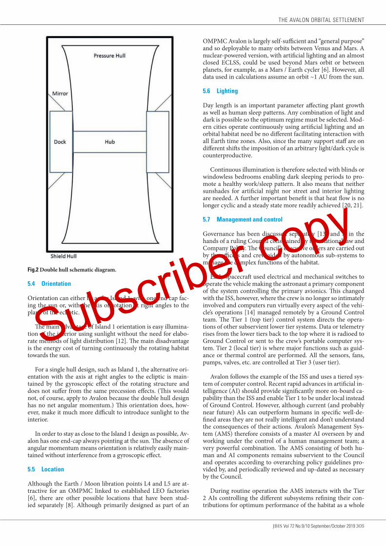
On balance, the advantages outweigh the disadvantages and Avalon has been designed with contra-rotating double hulls, shown schematically in Figure 2. It comprises a steel pressure hull with concave end-caps rotating inside a shield hull with flat end-caps made from reinforced AG. The maglev system is critical to a safe design and is dealt with in some detail in 6.4 and sub-paragraphs.
For convenience, the shaded end cap is designated South and the Sun facing one North with East and West as they are on Earth. The pressure hull rotates anticlockwise as seen from the North Pole (as does Earth) whereas the shield hull rotates clockwise.
STEPHEN GUNN & RICHARD SOILLEUX
Subscriber copy
JBIS Vol 72 No.9/10 September/October 2019 305
Fig.2 Double hull schematic diagram.
5.4 Orientation
Orientation can either be as for Island 1, with one end cap fac-ing the sun or, with the axis of rotation at right angles to the plane of the ecliptic.
The main advantage of Island 1 orientation is easy illumina-tion of the interior using sunlight without the need for elabo-rate methods of light distribution [12]. The main disadvantage is the energy cost of turning continuously the rotating habitat towards the sun.
For a single hull design, such as Island 1, the alternative ori-entation with the axis at right angles to the ecliptic is main-tained by the gyroscopic effect of the rotating structure and does not suffer from the same precession effects. (This would not, of course, apply to Avalon because the double hull design has no net angular momentum.) This orientation does, how-ever, make it much more difficult to introduce sunlight to the interior.
In order to stay as close to the Island 1 design as possible, Av-alon has one end-cap always pointing at the sun. The absence of angular momentum means orientation is relatively easily main-tained without interference from a gyroscopic effect.
5.5 Location
Although the Earth / Moon libration points L4 and L5 are at-tractive for an OMPMC linked to established LEO factories [6], there are other possible locations that have been stud-ied separately [8]. Although primarily designed as part of an
OMPMC Avalon is largely self-sufficient and “general purpose” and so deployable to many orbits between Venus and Mars. A nuclear-powered version, with artificial lighting and an almost closed ECLSS, could be used beyond Mars orbit or between planets, for example, as a Mars / Earth cycler [6]. However, all data used in calculations assume an orbit ~1 AU from the sun.
5.6 Lighting
Day length is an important parameter affecting plant growth as well as human sleep patterns. Any combination of light and dark is possible so the optimum regime must be selected. Mod-ern cities operate continuously using artificial lighting and an orbital habitat need be no different facilitating interaction with all Earth time zones. Also, since the many support staff are on different shifts the imposition of an arbitrary light/dark cycle is counterproductive.
Continuous illumination is therefore selected with blinds or windowless bedrooms enabling dark sleeping periods to pro-mote a healthy work/sleep pattern. It also means that neither sunshades for artificial night nor street and interior lighting are needed. A further important benefit is that heat flow is no longer cyclic and a steady state more readily achieved [20, 21].
5.7 Management and control
Governance has been discussed separately [13] and is in the hands of a ruling Council constrained by international law and Company Policy. The Council’s executive orders are carried out by the officers and crew aided by autonomous sub-systems to manage the complex functions of the habitat.
Early spacecraft used electrical and mechanical switches to operate the vehicle making the astronaut a primary component of the system controlling the primary avionics. This changed with the ISS, however, where the crew is no longer so intimately involved and computers run virtually every aspect of the vehi-cle’s operations [14] managed remotely by a Ground Control team. The Tier 1 (top tier) control system directs the opera-tions of other subservient lower tier systems. Data or telemetry rises from the lower tiers back to the top where it is radioed to Ground Control or sent to the crew’s portable computer sys-tem. Tier 2 (local tier) is where major functions such as guid-ance or thermal control are performed. All the sensors, fans, pumps, valves, etc. are controlled at Tier 3 (user tier).
Avalon follows the example of the ISS and uses a tiered sys-tem of computer control. Recent rapid advances in artificial in-telligence (AI) should provide significantly more on-board ca-pability than the ISS and enable Tier 1 to be under local instead of Ground Control. However, although current (and probably near future) AIs can outperform humans in specific well-de-fined areas they are not really intelligent and don’t understand the consequences of their actions. Avalon’s Management Sys-tem (AMS) therefore consists of a master AI overseen by and working under the control of a human management team; a very powerful combination. The AMS consisting of both hu-man and AI components remains subservient to the Council and operates according to overarching policy guidelines pro-vided by, and periodically reviewed and up-dated as necessary by the Council.
During routine operation the AMS interacts with the Tier 2 AIs controlling the different subsystems refining their con-tributions for optimum performance of the habitat as a whole
THE AVALON ORBITAL SETTLEMENT
Subscriber copy

306 Vol 72 No.9/10 September/October 2019 JBIS
[15]. The multifarious components of Tier 3 are computer con-trolled but subservient to the appropriate Tier 2 AI. Machine learning techniques are used to optimize performance in both subsystem AIs and the master AI.
Communications within Avalon are via WIFI and an in-tra-net (through which most electronic equipment is connect-ed) although critical sub-system AIs are connected directly to the master AIs by optical fiber. The steel pressure hull acts as a Faraday cage so all internal WIFI communications are shielded from the outside. Computers used for external communication do not have access to WIFI but are on a completely separate wired “Coms Net” connected to the WWW via fiber optic ca-bles to external antennae. All imported files are isolated and scanned before being allowed onto machines connected to the intra-net. Together, these measures protect Avalon’s control systems from external hacking.
The master AI behaves like a voice activated virtual assis-tant and responds to commands prefaced by the word “Avalon”. With some important exceptions, “Avalon” will accept and act upon commands from any occupant. The habitat is the ultimate “smart” town so a command such as “Avalon, turn off the lights in my bedroom” is accepted and acted upon for the comfort and convenience of all. “Avalon” recognizes individuals according to their biometric parameters and will not accept changes to pol-icy guidelines or other important operational parameters from unauthorized personnel. Consequently, operational details such as the ECLSS cropping schedules are only accessible to the ap-propriate workers to prevent frivolous or mischievous changes being made. Also, the master AI is privy to sensitive informa-tion, such as staff and medical records with very limited hu-man access. Over time, the master AI will amass huge amounts of personal information about individuals but this will not be accessible without good reason. Such reasons include issues concerning crime, health or danger to critical systems when the appropriate officers are granted access by the ruling Council.
Computer systems, located separately in the village tower blocks, host three identical interlinked versions of the master AI to provide redundancy in case of accident or malfunction. It also facilitates shift changes by the human component of the AMS with each arriving shift accepting control from the retir-ing shift by linking with the master AI in its local tower block. Perhaps more importantly, however, this allows all decisions to be taken independently by the three master AIs and com-pared for consistency with a majority decision being required for action. This is important because it is possible that the three master AIs will evolve separate operating algorithms over time because of minor differences in input data, not easily apparent to human overseers.
6 AVALON MAIN STRUCTURES
The materials required for construction are discussed first fol-lowed by descriptions of the main structures.
6.1 Main construction materials
Materials for the main structures are widely available from lu-nar and asteroid resources. The most important construction materials have been discussed in detail elsewhere [6, 9] but their key properties are summarized in the next section. The quantities required are given (in round numbers) in Table 1.
Other materials, including the essential volatiles of carbon
TABLE 1 Quantities of the main construction materials for Avalon
Raw material Construction material Quantity (kt)
Asteroid iron Maraging steel 17,000
Waste silicates Anhydrous Glass (AG) 43,000
Asteroid regolith Soil 1,130
Asteroid regolith Aluminium 600
Ices Water 400
Ices Air nitrogen 300
Ices Air oxygen 60
Total mass 62,490
dioxide, air and water, are also expected to come from asteroids [16]. They are also quantified in Table 1 but have been dealt with elsewhere [6] and are not discussed again.
6.1.1 Materials for pressure hull
Meteoric nickel iron is ideal for making maraging steels, which are iron-cobalt-nickel alloys. Most contain high proportions of Co which is relatively scarce in meteoric iron so the more re-cently developed Co free alloys [18] seem best for load bearing structures. The 18% Ni alloys (meteorites contain 6 – 35 wt%) are well suited to applications where heat treatment distortion and dimensional changes must be minimized and where high fracture toughness is required, such as rocket motor casings, aircraft landing gear and power shafts. They offer high strength (up to 2,000 MPa but, conservatively, 1,200 MPa is assumed here), high ductility, good formability, machinability, weld-ability and a low coefficient of thermal expansion. Vacuum melting, easy in space, minimizes contamination and ensures a consistent product [17].
6.1.2 Materials for external support structures
At high temperatures (200–250°C) aluminium alloys become weaker but at subzero temperatures their strength increases while retaining ductility [18]. This makes aluminium alloys ex-tremely useful at low-temperatures so they are used for some external support structures permanently in shade and especial-ly when they must be light in weight. A tensile strength of 340 MPa is assumed.
6.1.3 Materials for radiation shielding
Radiation shielding requires the most mass so should utilize the most abundant materials in NEAs, silicates and water ice (criterion 2.3). Water is best for shielding on a mass basis al-though the low density means that greater thicknesses are re-quired [5]; but, even as ice, it is problematic as a construction material. Water also has many other uses whereas silicates are adequate for shielding [5] but have little other utility and in-deed present a significant waste disposal problem (5.1.4). The absence of hydrolytic weakening processes in the strongly an-hydrous space environment makes vitrified silicates, or anhy-drous glass (AG), ten times stronger [18] than that made on Earth (average bending strength for flawed bars is 100 MPa). Although weak, compared to the metals and alloys available, it is strong compared to other abundant candidate shielding materials and offers new possibilities for orbital habitats [9].
Polythene, or other poly-hydrocarbons, have better radia-
STEPHEN GUNN & RICHARD SOILLEUX
Subscriber copy

JBIS Vol 72 No.9/10 September/October 2019 307
tion shielding properties than glass but, like ice, this is on a mass basis and the low density requires greater thicknesses [4]. Poly-hydrocarbons are strong but, unlike glass, their molecules start to break down on prolonged exposure to penetrating ra-diation. They are relatively expensive in space and therefore reserved for special purposes where low mass is important, re-placement easy and quantities relatively small.
6.1.4 Management of construction waste Waste management is vitally important to avoid the accumu-lating megatons of waste materials in orbit becoming a hazard, not only to orbiting spacecraft and factories but also to Earth itself [6]. It is therefore important that all parts of the NEA be consumed to avoid the fuel costs of deflecting the waste stream into a safe orbit.
In addition to safety concerns, maximum utilization of all parts of the raw materials expensively transported to L4/L5 is a key economic principle (3.3). Conveniently, an important side benefit of constructing habitats is the utilization for shielding [6, 9] and/or soil of the otherwise waste silicates that make up a large part (~35%) of the most attractive carbonaceous aster-oids [16].
6.2 Design of main structures
Figure 3 is a general cutaway view of Avalon looking through the shield-hull then pressure-hull past the central hub to the farms and villages at ground level. Also seen are the radial transfer shafts and end-cap greenhouses. The external radia-tors are shown and one spaceport service tube is visible but much detail has been omitted for clarity. The main structures are described in the following sections but much of the detailed design is given separately with construction [9] the ECLSS [10] and heat and water transport and balance [21].
6.2.1 Steel pressure hull
The pressure hull is 576 m long, 523.7 m in diameter and ro-tates at 1.32 RPM, generating ~1g on the internal surface. It is sized to withstand the atmospheric pressure, its own mass and
Fig.3 A general cutaway view of Avalon through both hulls into the interior.
the internal load (section 5.2.3) of three additional decks with internal fittings and machinery as well as soil, water and other contents including inhabitants.
Recent NASA guidance [19] is that, unless multiple EVAs are expected, space vehicles (including the ISS) should operate with Earthlike atmospheres and be pressurized at 101 kPa with 21% oxygen. Avalon complies with this conservative approach for the internal air pressure utilizing a value rounded to 100 kPa (10 t.m-2) for convenience. The hull is estimated to expand by ~1% when pressurized leading to an increase in diameter of ~10 m. There is just 6 m difference between the diameters of the outside of the pressure hull and the inside of the shield hull. It is therefore important that the pressure hull be made with a cor-respondingly smaller diameter than needed. Also, the internal structures are added after pressurization is complete.
Table 2 shows the hull loading (not including air pressure) is 6.52 t.m-2 with estimated average floor load of 1.69 t.m-2 (cf 1.6 t.m-2 for the Stanford Torus [2]). Peak values for floor load, and future requirements, are difficult to predict so the hull is designed to support 10 t.m-2 plus atmospheric pressure, a total of 20 t.m-2. For this a steel shell (strength 1,200 MPa) with a radius of 523 m requires a thickness of ~53 cm with a safety factor of 5.
TABLE 2 Mass of Pressure Hull layers and floor load Layer Thickness
(m)Density (t.m-3)
Radius (m)
Mass (kt)
Load 1g (t.m-2)
Steel 0.175 7.9 523.65 2,619 1.38
Support web 0.03 0.00215 523.47 0.122 0.000064
Steel 0.175 7.9 523.44 2,619 1.38
Support web 0.03 0.00215 523.27 0.122 0.000064
Steel 0.175 7.9 523.24 2618 1.38
Floor 0.03 4 519.06 225 0.12
Ground floor 0.03 4 515.03 224 0.12
Floor load 2,685 1.69
Total load 8,347 6.33
THE AVALON ORBITAL SETTLEMENT
Subscriber copy
308 Vol 72 No.9/10 September/October 2019 JBIS
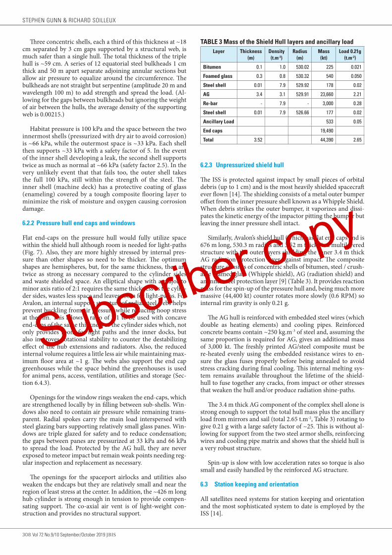
Three concentric shells, each a third of this thickness at ~18 cm separated by 3 cm gaps supported by a structural web, is much safer than a single hull. The total thickness of the triple hull is ~59 cm. A series of 12 equatorial steel bulkheads 1 cm thick and 50 m apart separate adjoining annular sections but allow air pressure to equalize around the circumference. The bulkheads are not straight but serpentine (amplitude 20 m and wavelength 100 m) to add strength and spread the load. (Al-lowing for the gaps between bulkheads but ignoring the weight of air between the hulls, the average density of the supporting web is 0.00215.)
Habitat pressure is 100 kPa and the space between the two innermost shells (pressurized with dry air to avoid corrosion) is ~66 kPa, while the outermost space is ~33 kPa. Each shell then supports ~33 kPa with a safety factor of 5. In the event of the inner shell developing a leak, the second shell supports twice as much as normal at ~66 kPa (safety factor 2.5). In the very unlikely event that that fails too, the outer shell takes the full 100 kPa, still within the strength of the steel. The inner shell (machine deck) has a protective coating of glass (enameling) covered by a tough composite flooring layer to minimize the risk of moisture and oxygen causing corrosion damage.
6.2.2 Pressure hull end caps and windows
Flat end-caps on the pressure hull would fully utilize space within the shield hull although room is needed for light-paths (Fig. 7). Also, they are more highly stressed by internal pres-sure than other shapes so need to be thicker. The optimum shapes are hemispheres, but, for the same thickness, they are twice as strong as necessary compared to the cylinder sides and waste shielded space. An elliptical shape with a major to minor axis ratio of 2:1 requires the same thickness as the cylin-der sides, wastes less space and leaves room for light-paths. For Avalon, an internal support structure of radial steel webs helps prevent buckling from air pressure while reducing hoop stress at the rim. This allows a ratio of 7:1 to be used with concave end-caps of the same thickness as the cylinder sides which, not only provides room for light paths and the inner docks, but also improves rotational stability to counter the destabilizing effect of the hub extensions and radiators. Also, the reduced internal volume requires a little less air while maintaining max-imum floor area at ~1 g. The webs also support the end cap greenhouses while the space behind the greenhouses is used for animal pens, access, ventilation, utilities and storage (Sec-tion 6.4.3).
Openings for the window rings weaken the end-caps, which are strengthened locally by in filling between sub-shells. Win-dows also need to contain air pressure while remaining trans-parent. Radial spokes carry the main load interspersed with steel glazing bars supporting relatively small glass panes. Win-dows are triple glazed for safety and to reduce condensation; the gaps between panes are pressurized at 33 kPa and 66 kPa to spread the load. Protected by the AG hull, they are never exposed to meteor impact but remain weak points needing reg-ular inspection and replacement as necessary.
The openings for the spaceport airlocks and utilities also weaken the endcaps but they are relatively small and near the region of least stress at the center. In addition, the ~426 m long hub cylinder is strong enough in tension to provide compen-sating support. The co-axial air vent is of light-weight con-struction and provides no structural support.
6.2.3 Unpressurized shield hull
The ISS is protected against impact by small pieces of orbital debris (up to 1 cm) and is the most heavily shielded spacecraft ever flown [14]. The shielding consists of a metal outer bumper offset from the inner pressure shell known as a Whipple Shield. When debris strikes the outer bumper, it vaporizes and dissi-pates the kinetic energy of the impactor pitting the bumper but leaving the inner pressure shell intact.
Similarly, Avalon’s shield hull (which has flat end caps and is 676 m long, 530.3 m radius and 3.52 m thick) is a multilayered structure with the outer layers shielding the inner 3.4 m thick AG radiation protection layer against impact. The composite structure consists of concentric shells of bitumen, steel / crush-able foamed glass (Whipple shield), AG (radiation shield) and an inner steel protection layer [9] (Table 3). It provides reaction mass for the spin-up of the pressure hull and, being much more massive (44,400 kt) counter rotates more slowly (0.6 RPM) so internal rim gravity is only 0.21 g.
The AG hull is reinforced with embedded steel wires (which double as heating elements) and cooling pipes. Reinforced concrete beams contain ~250 kg.m-3 of steel and, assuming the same proportion is required for AG, gives an additional mass of 3,000 kt. The freshly printed AG/steel composite must be re-heated evenly using the embedded resistance wires to en-sure the glass fuses properly before being annealed to avoid stress cracking during final cooling. This internal melting sys-tem remains available throughout the lifetime of the shield-hull to fuse together any cracks, from impact or other stresses that weaken the hull and/or produce radiation shine-paths.
The 3.4 m thick AG component of the complex shell alone is strong enough to support the total hull mass plus the ancillary load from mirrors and sail (total 2.65 t.m-2, Table 3) rotating to give 0.21 g with a large safety factor of ~25. This is without al-lowing for support from the two steel armor shells, reinforcing wires and cooling pipe matrix and shows that the shield hull is a very robust structure.
Spin-up is slow with low acceleration rates so torque is also small and easily handled by the reinforced AG structure.
6.3 Station keeping and orientation
All satellites need systems for station keeping and orientation and the most sophisticated system to date is employed by the ISS [14].
TABLE 3 Mass of the Shield Hull layers and ancillary load Layer Thickness
(m)Density (t.m-3)
Radius (m)
Mass (kt)
Load 0.21g (t.m-2)
Bitumen 0.1 1.0 530.02 225 0.021
Foamed glass 0.3 0.8 530.32 540 0.050
Steel shell 0.01 7.9 529.92 178 0.02
AG 3.4 3.1 529.91 23,660 2.21
Re-bar - 7.9 - 3,000 0.28
Steel shell 0.01 7.9 526.66 177 0.02
Ancillary Load 533 0.05
End caps 19,490
Total 3.52 44,390 2.65
STEPHEN GUNN & RICHARD SOILLEUX
Subscriber copy

JBIS Vol 72 No.9/10 September/October 2019 309
6.3.1 The ISS motion control system (MCS)
The MCS maintains the ISS in a constant attitude for day-to-day operations and makes adjustments to accommodate visit-ing vehicle dockings and captures. It also re-boosts the orbit to counter atmospheric drag or avoid space debris [14]. The sys-tem uses Global Positioning Satellites (GPSs), rate gyroscopes, and other sensors to “know” its location and orientation as it circles the Earth. These data are also used to point solar arrays at the sun, antennas to communications satellites, and payloads to ground or other targets.
The ISS carries several tons of hypergolic propellant which must be replenished periodically. It is the only satellite for which this is possible; other satellites reach the end of their useful lives when it runs out.
6.3.1 Station-keeping and orientation for Avalon
Like the ISS, Avalon’s MCS needs sensors so it “knows” its lo-cation and orientation as it orbits L4/L5 and can point its so-lar arrays at the sun, antennas to communications satellites, and payloads to Earth or other targets. By the time Avalon is built there will probably be a system of navigational satellites in HEO and in lunar orbit in addition to GPS. It will therefore use a similar system to the ISS including gyroscopes and sun and star positioning sensors to ensure correct orientation and positioning in orbit.
The primary role for Avalon is to provide support for an or-bital manufacturing facility and as such is normally embedded within the factory complex the various components of which are linked so they move together. They must therefore retain orientation and station-keeping as a whole to manage the evolving orbit around L4/L5 and this is described in a separate paper [6] but station-keeping and attitude control for Avalon as an isolated entity is covered below.
In most orbits, including HEO, once the MCS starts Avalon
turning by the required 1°/day it will continue to do so unless perturbed in some way. Under these circumstances, the MCS is only required to correct such perturbations. However, at L4/L5 although 1°/day turning rate is still necessary the habitat must also first yaw in one direction then the other as it orbits the libration point. As well as dealing with irregular perturbations, the restoring mechanism must therefore also correct for these more regular variations in orientation.
With Avalon as an isolated spacecraft orbiting L4/L5, grav-itational perturbations mandate a system with a performance comparable to the shuttle OMS requiring large amounts of pro-pellant (44 kt / year) [6]. Following the example of the ISS with its electrically driven gyroscopes, Avalon also requires a differ-ent type of MCS to avoid these enormous fuel costs. However, unlike the ISS Avalon rotates to generate artificial pseudogravi-ty complicating the operation of all types of MCS. Descriptions of how gyroscopes or reaction wheels might be adapted for a rotating spacecraft as large as Avalon are given elsewhere [22] but the complexities are such that a third available method has been selected, a solar sail, as the primary MCS. Avalon requires a large solar sail as the main station keeping method. It is frag-ile and subject to damage but, fortunately, excessive drifting into unsuitable orbits will be slow allowing time to cope with any malfunction.
6.3.1 Solar sails for station keeping
Details of the design for Avalon’s solar sail are reported sepa-rately [22] and will not be repeated here but the main features are given for clarity. The sail is 9 km square [6] and located ~15 km to the South of the habitat attached to the outer edge of the shield hull by cables so rotates with it (Figure 4).
By using liquid crystal screens in front of some of the solar cells to switch the reflectivity on and off [22] it should be pos-sible to steer the array. These LCD panels operate sequentially, keeping pace with the rotation, in order to provide the syn-chronized thrust necessary for steering. There is a 1 km square hole in the center for space craft to enter safely without coming
Fig.4 Main features of Avalon’s solar sail.
THE AVALON ORBITAL SETTLEMENT
Subscriber copy
310 Vol 72 No.9/10 September/October 2019 JBIS
near the rotating parts (5.6.1).The energy required to operate the sail is provided by thin
film solar cells mounted on the sunward face.
6.3.2 Solar sails to maintain orientation
Because the solar sail required for station keeping is always deployed it is also used to maintain the correct sun pointing orientation, in effect acting as a drag anchor or the fin on a weather vane.
6.4 Rotational instabilities and maglev system
As already discussed, the system, as a whole, is rotationally stable. Both hulls are within the radius to length stability limit ratio of 1.3 [4] at 1.1 and 1.27 for the pressure and shield hull, respectively.
It is vitally important that both hulls are manufactured to very high tolerances to avoid any unsymmetrical distribution of mass and a built-in tendency to wobble. Accuracy is also necessary because of the need for sufficient clearance between the contra-rotating cylinders. For example, if a hull of 1,000 m diameter is oval instead of round by as little as 1%, this equates to a 10 m bulge, which is unacceptable. Both hulls are therefore constructed by 3d printing in a jig-factory [6, 9] to ensure the “print heads” rotate very accurately to lay down the hull matrix to very fine tolerances.
Also, mass must be distributed evenly around the circum-ference of both hulls when building both internal and external structures to minimize wobble on spin-up. Temporary changes in mass distribution are inevitable in an occupied habitat, how-ever, as vehicles, equipment, goods and people move around. These cause small changes in hull spacing; measured accurately with lasers and countered by automatically pumping water be-tween ‘trim’ tanks round the inner hull. This is similar to sta-bilizing systems used on modern submarines, but on a much larger scale. The movement of large items is planned for and mass redistributed to minimize the effects. To facilitate coun-terbalancing, most of the stores are on wheels and moved as necessary.
The ventilation system moves large masses of water from the rim farms and end-cap greenhouses to the hub condensers. For a habitat with a day/night growing cycle the twice-daily re-dis-tribution of mass causes the rotation rate to vary cyclically (by a small amount) to conserve angular momentum. Avalon, how-ever, is illuminated continuously so water returns to the rim at the same rate as it is transported to the hub [20] and there is no change in rotation rate.
For a single hull, wobble is most noticeable at the axis, which starts to orbit round the new center of mass. This is a potential problem for docking or undocking spacecraft as well as un-comfortable for occupants of the hub and axis facilities. At the rim there is much less effect, only a small difference in apparent gravity, most noticeable with large bodies of water.
For the double hull system, there is some buffering of shocks by the hydraulic suspension of the maglev system but sustained slow movements transfer the imbalance to the outer hull.
6.4.1 The maglev system
The counter-rotating hulls risk catastrophic failure [4] should
they make contact so management of this critical risk is dis-cussed in some detail. Of utmost importance in this regard is the maglev system keeping the inner and outer hulls apart.
6.4.1.1 Estimate of maglev system requirements
The various forces acting on the orbiting habitat that must be resisted by the maglev system can be summarized as follows.
(1) Internal forces imposed by station-keeping. (2) Collisions with spacecraft or meteorites.(3) Internal forces imposed by the habitat’s precession to
maintain sun-facing orientation for the solar cells. (4) Perturbations from internal displacements of mass, inclu-
di ng large movements of people.
To manage these internal forces, it is estimated that an inter-nal maglev system capable of delivering forces >100kN (equiv-alent to 10.2 t at 1 g) is required [6], similar to the axle load of the driving wheels (>10t) of a typical articulated lorry. This should be sufficient to absorb collisions by spacecraft as mas-sive as the shuttle orbiter up to relative velocities of 40 m.s-1 or impacts from meteorites <400kg. It should also be able to cope with a rapid redistribution of mass, up to (for example) a cat-astrophic collapse of internal decking spanning ~40m or mass evacuation of the population.
Although the maglev system keeps the two hull axes paral-lel, the steady precession forces acting on the suspension tends to twist them slightly out of alignment with ends of the two axes appearing to orbit one another. Provided, however, that the maglev / suspension system meets the above requirements this effect will be very small and not noticeable even for dock-ing spacecraft.
6.4.1.2 Choice of maglev technology
A number of maglev technologies exist but electrodynamic suspension (EDS) systems are dynamically stable. Changes in distance between the track and the magnets create strong restoring forces so no active feedback control is needed. EDS systems levitate but do not propel so require separate linear motors for propulsion.
A more recent development of EDS is magnetodynamic suspension (MDS), which uses the attractive magnetic force of a Halbach array of permanent magnets near an aluminium or stainless-steel clad steel track for lift and stability [24]. A self-regulating MDS system therefore provides levitation while propulsion and guidance come from a permanent magnet lin-ear synchronous motor [24]. This method provides failsafe suspension because no power is required to activate levitation magnets.
The concept is under development as the Inductrack sys-tem [24]. The Halbach array utilizes permanent-magnets to produce a periodic and concentrated magnetic field below the array while canceling it above. This not only makes for more efficient use of the magnets but also avoids strong magnetic fields inside the vehicle. (Avalon’s thick steel triple pressure hull would also provide effective magnetic screening internally. Similarly, the steel shells protecting the AG shield hull screen the exterior to prevent damage to sensitive instruments as well as robots working outside.) Furthermore, the track consists of a close-packed array of shorted circuits to optimize the in-ductive coupling between the moving Halbach arrays and the
STEPHEN GUNN & RICHARD SOILLEUX
Subscriber copy

JBIS Vol 72 No.9/10 September/October 2019 311
stationary elements. Such an arrangement maximizes the ac-tive area generating the levitating force. As a result of these two optimizing factors, high-field magnetics (such as NdFeB) with remnant fields in excess of 1.2 Tesla can provide levitating forces of ~40 t.m-2 with magnets weighing as little as 2% of the levi-tated weight [24]. Since it is an induced-current repulsive-force system, levitation is only achieved when the vehicle is moving. However, the transition speed (defined as the speed when the levitation force rises to half its asymptotic value) for the Induc-track design [24] is typically 5 km/h (1.4 m.s-1) – walking speed.
Levitation and propulsion magnets are mounted in “bogies” that also support the coiled spring suspension units required to cope with minor irregularities in the track. This provides a safe system which cannot derail under any operational conditions. The stainless steel-clad shorted copper levitation coils in the track result in a system with no moving parts, high reliability and ease of maintenance. This is of particular benefit in the vac-uum between Avalon’s moving hulls avoiding potential prob-lems from complex and expensive superconducting magnets.
An important feature for the Avalon design is that the drive/lev units are fixed to the inside of the shield hull for ease of maintenance and, because (unlike train carriages) they cannot move, collisions between them are impossible. Also, the drive/lev units need neither active control nor power systems so the control room for the linear motors in the track can be located inside the pressure hull. The electricity supply for the propul-sion motors comes from PV cells fixed behind the mirror rings passes through the shield hull and drives the brushless motors of the linear motors by inductance coupling to minimize wear and consequently maintenance requirements. However, this critical system can also be powered through the pressure hull
from the main Avalon supply which is completely independent from the mirror ring arrays.
The Lift/Drag ratio increases linearly with velocity [24] and is given by
Lift/Drag = (2πv/λ) x (L/R) (1)
This expression can be used to evaluate the levitation effi-ciency, that is the Newtons of levitating force per Watt of power dissipated in the track.
Also; K = (2π/λ) x ( L /R) Newtons/Watt (2)
The relative velocity between the counter-rotating hulls (shield hull 33 m/s + pressure hull 71 m/s) totals 104 m/s, 374 km/h. The lift/drag relationship is linear and the graph in reference [24] shows that at 104 m.s-1, 374 km/h, L/D = ~200 (compared to ~25 for the wing of a jet aircraft). Combining equations (1) and (2) (from reference [24]) gives equation (3):
K = (L/D)/v (3)
Where K (N/w) is the power efficiency and v (m.s-1) is velocity.
Therefore: 200/104 = 2 N/w (2 kN/kw)
Consequently, the power for drive/lev at 104 m.s-1 is ~200 kw for a 40 t load. The Avalon maglev system would therefore need ~50kw to provide the 10.2 t of force necessary. This analy-sis ignores aerodynamic drag which will not occur between the Avalon hulls rotating in hard vacuum.
Fig.5 Magnetic levitation, propulsion and guidance systems.
THE AVALON ORBITAL SETTLEMENT
Subscriber copy

312 Vol 72 No.9/10 September/October 2019 JBIS
A more recent development of the Inductrack system [25] uses a double Halbach Array of levitation magnets combined with Litz cable for the track. (Litz multistrand cable is used to carry alternating current (AC) at radio frequencies to reduce losses in conductors.) These improvements result in signifi-cantly reduced magnetic drag for a given lift force and a stiffer primary suspension system.
Double levitation arrays with propulsion, and guidance sys-tems, adapted slightly for Avalon, are seen in Figure 5. It shows the 1 m wide, 4 m long, arrays of levitation magnets in relation to the cantilevered ladder track which consists of loops of Litz cable shorted at the ends with copper. The linear synchronous motor (LSM) windings are three-phase and interact with the field generated by the propulsion magnets on the drive/lev unit (a peak drive force of ~25 kN was measured for the test vehicle [25]). The propulsion permanent magnets also provide guid-ance by interacting with the LSM iron lamination rails. The magnets of the LSM are housed in stainless-steel sheathing as are the rows of Halbach-array levitation magnets.
Both sets of rails are located within 1 m of the pressure hull to allow 2 m of headroom for workers standing on the shield hull during inspection and maintenance of the “stationary” drive/lev units. Figure 5 also shows the backup wheeled bear-ing system required for the initial spin-up and in case of a com-plete power failure (see end of next section).
One of the notable characteristics of the Inductrack system is that its levitation and drag parameters can be analyzed theo-retically and evaluated with high confidence through computer codes validated by experiment. This would be invaluable for optimizing the Avalon design.
6.4.1.3 Performance required for a single drive/lev unit
For simplicity it is assumed that the two counter-rotating hulls separated by the maglev suspension system behave as a journal bearing. It is further assumed that forces are normal to the con-tact surfaces and clearance between them is negligible (~0.1 m maglev suspension gap [24]) but that the parts cannot deform elastically (the suspension system can move <0.1 m, 0.01% of hull diameter). Under these conditions the contact pressure is
Fig.6 Precessional forces between the hulls where L is the distance between the 3 maglev tracks at one end. Distances between the hulls are exaggerated for clarity.
essentially uniform (Figure 6). The maximum pressure between the hulls (Pm a x) can then
be calculated from equation (4):
Pm a x = F /L D (4)
Where F is the load, L is the length over which the load is supported and D is the diameter of the inner cylinder.
The previous analysis shows that perturbations from impact and instabilities from internal and external mass movements should be manageable by a restoring force of some 100 kN. The maximum pressure (Pmax) is shared equally between the two ends of the double hull so each must support 50 kN. The MDS maglev system, however, produces a restoring force that “pulls” as well as “pushes” so the load is shared equally between the “top” and “bottom” of the bearing surfaces. Each side of each end must then support 25 kN. Furthermore, the end load is shared between three sets of maglev tracks each of which must support no more than ~8 kN.
On this basis, Pmax = 8/(75x525) = 0.2 N.m-2 (5)
Consequently, an individual suspension unit (nominally 1 m2) must support a maximum force of just 0.2 N, negligible compared to the ~100 - 400 kN per m of track (see section 5.3) required by the individual bogies of a maglev train. Of course, this also means that the Avalon maglev system provides a much more powerful levitation force than necessary for nor-mal operation making it very robust and capable of managing quite severe impacts. The drive system, after initial spin-up, is required only to overcome magnetic drag so needs much less power than a train.
Stress from the turning moment of precession is greatest at the cylinder ends where sets of three maglev tracks, 25 m apart, are used for triple redundancy. This spacing is also chosen be-cause magnetic force decreases rapidly with distance (inverse square law) so is negligible at 25m avoiding potential problems arising from interaction between the tracks. Each track has 130 completely independent drive/lev units spaced ~25 m apart around the 3,310 m circumference. The units are off-set from each other in adjacent tracks (i.e. each track is shifted by 8.3 m
STEPHEN GUNN & RICHARD SOILLEUX
Subscriber copy
JBIS Vol 72 No.9/10 September/October 2019 313
around the circumference with respect to the next). This both maximizes the distance between them and spreads the load so, in effect, there is a supporting unit every 8.3 m around the cir-cumference at each end of the hulls. Each unit can be removed individually for planned maintenance and servicing (Figure 5) and this procedure also enables faulty units to be repaired.
A power cut would cause the entire system to slow and eventually stop with a complete loss of pseudogravity, guarded against with two separate back-up power supplies (6.5.1.2). In the unlikely event that this should also fail, a wheeled second-ary bearing system ensures that the system would fail-safe.
This fail-safe arrangement must work reliably after perhaps decades of inaction with minimal maintenance so multiply redundant, simple mechanical systems are used. Steel wheels, attached to the same suspension units that support the drive/lev magnets, ride on steel rails running alongside each of the maglev tracks (Figure 5). (Both wheels and track are made from non-magnetic stainless steel to avoid interference with the maglev system.) The wheeled system also supports and separates the hulls during construction and initial spin-up. During the first stage of spin-up, the rotation rate soon reach-es the transition velocity for magnetic levitation and the wheel assemblies are withdrawn into the drive/lev units by solenoids and held against springs ~10 cm above the track. On reach-ing the full extent of withdrawal, pins are inserted to hold the assemblies against the springs and power to the solenoids is cut. The pins operate against springs and are held in place ever more firmly by a system of levers pushing against the springs by weights which become “heavier” as the pseudogravity of the rotating shield hull increases to its maximum. If, howev-er, both primary and secondary power supplies fail magnet-ic drag causes the rotation rate to decrease slowly. Just before the transition speed is reached and maglev is lost, the effect of pseudogravity becomes insufficient for the weights to hold the pins against their springs so they withdraw releasing the main springs which push the wheels onto the rails.
Although this fail-safe system should be very reliable, no mechanism can be expected to always operate perfectly over such long time periods under vacuum and low temperature. The drive/lev units are therefore subject to a regime of periodic preventative maintenance when they are taken off-line (drawn to the left in Figure 5) and serviced. Even so, 100% reliabili-ty cannot be guaranteed but with so many independent units spread over three tracks at each end or the cylindrical hulls it does not matter if some wheels are not released when required.
6.4.1.4 Maglev to support Avalon within the factory complex
Although Avalon is designed to be general purpose, capable of operating as an individual component of a future orbital econo-my, its primary role is to provide support for an OMPMC [6]. In this role, it is embedded in the plane of the non-rotating megas-tructure of the complex and requires a robust support system. The maglev system provides such a support system between the two hulls which, as described above, are free to counterrotate. In its OMPMC configuration, the shield hull could, in principle, be attached directly to the main support framework preventing it from rotating but leaving the pressure hull free to turn within it. The disadvantage of this approach is that during spin-up / spin-down the considerable angular momentum of the pressure hull would be transferred directly to the entire complex and re-quire much effort to prevent it from rotating in turn. Even dur-ing normal operation, magnetic drag, compensated for within
Avalon’s maglev system by the linear drive motors, would cause a small amount of angular momentum to be transferred con-tinuously to the megastructure and require a correspondingly similar force to be applied constantly to resist it.
Consequently, Avalon is not attached directly to the OMP-MC structure but instead is free to rotate within it support-ed by a maglev system very similar in performance to the one described above. The main difference is that the linear drive motors of the external system push the rotation of the shield hull in the opposite direction to their internal counterparts cancelling the tendency to transfer angular momentum to the main structure. Both internal and external linear drive systems are controlled and coordinated by the internal AMS to ensure optimum rotation rates are maintained. The external maglev system is so similar to the internal one that it need not be de-scribed separately.
6.5 External structures
All external support structures are made from aluminium (5.1.2). This is important for structures in permanent shade be-cause aluminium retains its strength at low temperatures. Also, its low mass helps with structures located outside the end-caps because of rotational stability issues [4].
6.5.1 Power supply and mirror rings for lighting
The main supply comes from solar cells mounted at the sun-ward facing end-cap (264 MW) and IR optimized PV cells fas-tened behind the cold-light mirror rings (up to 29 MW availa-ble, probably more than required). Electricity from the mirror rings supplies the linear drive motors of the maglev system and other facilities attached to the shield hull whereas the hub and internal habitat facilities are powered from the end cap array. The heat balance for Avalon is discussed elsewhere [21].
6.5.1.1 Solar cells
The solar power disc is fixed to the sunward end of the radia-tors, shading them completely while avoiding any shading of the solar cells. These are also made largely from aluminium and are relatively thin fragile structures so do not contribute much to instability. The PV cells degrade over time so are designed to be replaced easily from the rear by robots travelling through the support framework.
6.5.1.2 Back-up power supplies
As a precaution against major damage to the solar power ar-rays and/or the electrical transmission system, backup pow-er supplies are essential for all components of the OMPMC. Power is critical to the safe operation of Avalon’s complex life support systems so it uniquely has a second back-up arrange-ment. These together guard against a complete power-cut even if all the sun-facing (North) structures of power disc, radiators / rectennas were to be lost to a major asteroid strike or collision with a spacecraft, considered to be the worst credible catastro-phe that could affect Avalon [29].
(a) OMPMC power grid The various components of the OMPMC megastructure, which includes Avalon, have their own individual PV arrays arranged in a basic grid to reliably supply the con-suming facilities [6]. Like a terrestrial power grid, this arrangement ensures that power continues to flow if one
THE AVALON ORBITAL SETTLEMENT
Subscriber copy

314 Vol 72 No.9/10 September/October 2019 JBIS
component suffers failure. (b) Rectenna array In case connection to the grid should be lost at the same
time the habitats own primary supply fails the second method of power supply is deployed automatically. This consists of sets of wires stretched between the outer edg-es of the radiator panels to form a rectenna (rectifying antenna) able to receive power beamed from the factory complex. (The wires also have a secondary role in brac-ing the radiator panels into lightweight but ridged struc-tures.) Radiators are mounted at both ends of the habi-tat so the attached rectennas are duplicated. Assuming a power density of 1 kW.m-2 and a rectenna area of 250,000 m2 at each end, then a power input of 250 MW can be expected (500 MW from both arrays).
6.5.1.2 Mirror rings
Fig.7 General external appearance of Avalon
The external cold-light mirror / power rings are shown in Fig-ure 7 together with the chevron shaped openings in the shield hull that allow light to enter while harmful radiation is blocked (see figure 9). The mirrors are fixed to the more slowly rotating shield hull within the end-caps so contribute to, rather than detract from rotational stability.
The mirrors are attached to the shield-hull through which electricity, generated by the IR optimized solar cells fixed be-hind them, is transmitted via aluminium conductors to the in-ternal, lighting and maglev power systems. Power for external lights and for re-charging batteries of maintenance robots, also comes from this system.
The solar cell disc rotates with the radiators and pressure hull so power cables run directly through the access tube and North dock to the interior. Aluminium conductors are used for cheapness and because the radiation protection characteristics
Fig.8 External view of one end of the pressure hull showing one set of internal mirror and window rings.
STEPHEN GUNN & RICHARD SOILLEUX
Subscriber copy

JBIS Vol 72 No.9/10 September/October 2019 315
are similar to glass and better than copper, which generates more secondary, charged particles.
Sunlight enters the interior via a static system of mirrors and
windows (Figures 8 and 9) designed to provide an even spread of illumination.
Figure 9 shows how the incoming light rays are angled so as to illuminate evenly the inside at an intensity of 10,000 lux at ground level [20, 21].
Continuous internal illumination ensures that lighting can-not fail provided the habitat maintains correct orientation. Light pipes to lower decks ensure that no areas are completely dark although rooms deep within the structure use LED light-ing.
6.5.1.3 Radiators
The cooling system is critical to maintaining a habitable en-vironment but the external radiator systems are vulnerable, at risk of damage by meteorite impact or collision with maneu-vering spacecraft. They are therefore of modular construction to provide built-in multiple redundancy. A set of four radiators is mounted outside each hub (Figure 6) keeping the two com-pletely separate cooling systems as far apart as possible. Mount-ed axially outside the rotationally stable hull configuration the radiator clusters have the potential to adversely affect rotation-al stability so are made from aluminium to save mass. They are connected to, and rotate at the same speed as, the pressure hull to allow the coolant pipes to run directly to the hub air-condi-tioners.
A total space facing radiating area of 1.37 km2 is required
Fig.9 Shows how light enters the interior.
to provide the necessary cooling capacity [20]. Since heat is emitted from both sides the radiators themselves can be half this size at 0.69 km2. In practice, however, they are 1 km2 (pro-viding 2 km2 space facing area, ~45% extra) to allow for loss of capacity by damage to individual coolant pipes (see below). This extra capacity becomes crucial in case one radiator cluster should suffer catastrophic damage when the remaining cluster could just provide cooling for the habitat in emergency shut-down mode. During normal operation the cooling system runs at less than full capacity to compensate and thereby maintain the desired internal temperature.
Each of the 4 panels in each radiator cluster has its own set of coolant pipes running directly to the hub air conditioners, to give a total of eight independent cooling modules in case of failure. Furthermore, individual coolant pipes inside the radi-ators form separate U tubes so pressure balances across each pair of arms and pumping requirements are minimal. Non-re-turn valves are fitted where they join the main hub pipes to minimize coolant loss in the event a meteorite punctures a U tube. In addition, linked dump valves at the “bottom” of each U tube drain the remaining water-based coolant to prevent it freezing before repairs can be performed. Maximum internal pressure at each U bend is ~25 bar, high, but manageable.
6.6 Spaceports
Two spaceports, one located at each end of the hub, provide redundancy as a safety measure but also increase capacity and provide flexibility. Each spaceport consists of outer and inner docks connected by a service tube. The outer docks enable in-coming spacecraft to be captured efficiently and safely. Onward transfer to the inner docks is via 400m long service tubes which guide a spacecraft, or its cargo / passenger pod, through the
THE AVALON ORBITAL SETTLEMENT
Subscriber copy

316 Vol 72 No.9/10 September/October 2019 JBIS
complex structure of Avalon’s solar panels and radiators, and through its radiation shielding. (Figure 10). The inner docks contain large workshops for the construction and repair of spacecraft protected from radiation but open to vacuum. They also contain the airlocks which control access into the pres-surized interior of the habitat at the hub where visitors can be processed in comfort and moved to their assigned accommo-dation.
6.6.1 Spacecraft
Before the spaceports and spacecraft entry / exit procedures are described it is helpful to discuss briefly, the types and sizes of spacecraft to be accommodated. The following three examples are thought to cover the range of space vehicles foreseeable, at least during the early years of the Avalon’s existence. Univer-sal Space Interface Standard (USIS) docking / berthing ports [26] are used for Avalon’s 6 airlocks and for all vehicles and transport containers operating throughout the OMPMC and it is expected that all visiting spacecraft will also be so equipped. USIS ports have an androgynous design so they can berth or dock to identical replicas of themselves.
(a) Based on the principle of Skylon transfer spacecraft design (Figure 11), a system with a tug and detachable cargo passenger pods is assumed to be the main work-horse vehicle and much of Avalon’s spaceport is designed around this concept. This gives great flexibility and allows the tugs to be fully utilized and remain docked only long enough to exchange pods and re-fuel. Pods are 13 m long and 4.5 m in diameter. While the tugs themselves, both manned and unmanned, are of bespoke design, the pods are mass-produced shells that fit within the Skylon cargo area and are then fitted out for specific purpose, either as cargo containers or passenger carriers capable of ac-commodating 30 people. These have an integral ECLSS and supplies for a week, more than sufficient for the 3-day
Fig.10 Axial transport routes from the outboard docks to the shielded inner docks and hub facilities then radial transfer shafts to ground level.
trip from LEO. Many are held within Avalon’s inner docks as lifeboats in sufficient numbers to evacuate all 10,000 inhabitants. At least two pods are fitted out with micro-gravity-adapted surgical and diagnostic equipment and serve as ambulance units for the surrounding factories and research facilities. [27.]
(b) SpaceX’s proposed interplanetary spacecraft, at 50 m long and 20 in diameter, is the largest type that could be brought inside the shield hull and accommodated in Av-alon’s workshops. Other than size, very little information is available other than that it has the capacity to transport 100 passengers.
(c) Scorpion is designed as a general-purpose nuclear-pow-ered vehicle [28] capable of undertaking long interplane-tary missions. It is 107 m long, 50 m wide and 13 m high and can vary in mass from around 240 tonnes when emp-ty to around 1,000 tonnes fully fueled and loaded. As it
Fig.11 Tug with detachable cargo / passenger pod.
STEPHEN GUNN & RICHARD SOILLEUX
Subscriber copy

JBIS Vol 72 No.9/10 September/October 2019 317
stands, a Scorpion is too big to be accommodated even temporarily in Avalon’s outer docks and certainly could not be brought inside. In any case, nuclear-powered craft are unlikely be allowed inside the shield hull on radiation safety grounds.
Scorpions, and any other type of large interplanetary craft, would therefore have to be serviced and repair and mainte-nance work carried out at a docking station within the factory complex. The Scorpion’s main provision for carrying payloads are six USIS berthing ports [28] capable of accommodating six of the standard 13 m long pods described above. After undock-ing, arriving cargo and/or passenger pods would become part of the local traffic being ferried from the Scorpion along the OMPMC rail system by tractor units (versions of the spaceport transport cradles described below) to Avalon’s outer docks.
Versions of Avalon not associated with manufacturing but operating in relative isolation might need to be visited regularly by Scorpions and require outer docks large enough to accom-modate them.
6.6.2 Docks, docking, transfer and berthing
Even without rotation, docking can be difficult [30] as practi-cal experience with Mir and the ISS [14] shows. Furthermore, multiple experiments (by Gunn) using Martin Schweiger’s open source Orbiter Space Simulation software [30] show that, unless spacecraft are perfectly aligned prior to rotation, it is al-most impossible to make corrections manually. It is therefore not practical with currently available control systems to move a rotating spacecraft accurately in three dimensions.
6.6.2.1 Docks and dock equipment
To avoid the problem of docking with a rotating structure, Av-alon’s outer-docks can counter-rotate to cancel the spin of the service tubes. They do not rotate continuously, however, but normally remain locked to the spinning service tubes so are al-ways available for departing spacecraft in an emergency. While no spacecraft can remain attached at an outer dock for long because of adverse effects on the settlement’s rotational stabil-
ity, tugs can be refueled or transferred to the inner dock under shielding. Being located singly at the axis also means that they do not much affect rotational stability.
All approach / departure and docking / un-docking operations are computer controlled, directed by Avalon’s computerized Dock Management System (DMS, a Tier 2 AI).
(a) Outer docks The outer-dock is 45 m internal diameter and 70 m long
and fits inside the end of the 50 m external diameter 400 m long service tube supported by a maglev system smaller than but similar to the main system (5.4.2). Two rings of drive/lev units are attached around the outside of each end of the dock facing a pair Litz tracks mounted inside the service tube. The linear drive motor coils are also fixed inside the service tube with ready access to the main power supply when rotating the dock. The relative-ly trivial mass of the outer dock compared to the rest of the habitat means that the amount of angular momentum transferred to the habitat during spin-up / spin-down is negligible. At full speed, the outer rim of the counter-ro-tating dock travels at 7.6 m.s-1 with respect to the rotating service tube, 5 times more than the 1.4 m.s-1 necessary for effective levitation. During the initial and final stages of spin-up / spin down, respectively, the dock is supported by wheels attached to the drive/lev units acting on tracks around the inner surface of the service tube. The outer docks are powered directly from the main solar disc via brushes and slip rings to maintain supply during coun-ter-rotation. This system is subject to wear so requires regular maintenance and repair.
Each outer dock is equipped with three manipulator arms similar in basic design to those used by the space shuttle and the ISS, but engineered to a handling capacity of around 300 t (more than twice the mass of the space shuttle). It also ac-commodates the end sections of the three transfer rail tracks equipped with transport cradles, mobile platforms designed to ferry incoming spacecraft and cargos along the rails to the in-ner docks (Figure 12). The end sections of track are mounted on platforms 11.5 m above the surface of the dock to match
Fig.12 Outer docking area showing an approaching spacecraft, and transport rails.
THE AVALON ORBITAL SETTLEMENT
Subscriber copy
318 Vol 72 No.9/10 September/October 2019 JBIS
the height of the rest of the system and conform to the restric-tion of the bottleneck through the shield hull (see section (b) below). The manipulator arms are located between the rail platforms clamped to their own sets of rails enabling them to traverse the full 70 m length of the dock. They can therefore reach outside to capture a spacecraft (or recover a pod from a tractor unit) then withdraw into the dock to place it on the cra-dle prelocated on the appropriate track section. Their location between the raised platforms enables the arms to fold down to accommodate larger spacecraft without further compromising the constraint on diameter already imposed by the bottleneck.
The cradle bed consists of eight hundred hydraulically con-trolled rods, each with a sprung and padded end, designed to accommodate any size and shape of vessel and to distribute load evenly without damage. The cradles are effectively “low loaders” with the beds rising no more than 1 m above the rails but with the telescopic rods able to move up further to conform to the geometry of a pod or other spacecraft. Clamps on the cradle then attach to the handling points on the spacecraft to secure the load for transfer into the interior during which no great inertial shocks are expected.
Once the spacecraft is secure on the cradle, the counter-rota-tion of the dock is cancelled slowly until the rotation rate again matches the service tube. The DMS manages the spin-down until synchronization is complete and the three track platforms line up with their respective transfer rail systems when they become locked. Furthermore, the DMS ensures that an incom-ing pod is connected to the appropriate route to its designated elevator and airlock.
Since there are three independent tracks connecting to three elevators and airlocks, it is possible to accommodate and trans-port three standard pods at the same time at each spaceport. Although only a small amount of incoming traffic is expected, many cargo pods pulled by robot tractors will be moving mate-rials and goods between Avalon and the factory complex keep-ing all three tracks busy. Having three independent transport routes also enables local traffic to continue uninterrupted by visiting spacecraft. Large interplanetary craft such as Scorpi-on would necessarily dock within the factory complex with its cargo and passengers transshipped to pods, added to the local traffic and handled in the usual way. During an evacuation, full capacity would enable three “lifeboats” to be launched at a time from each spaceport.
Much larger spacecraft than the standard pods can also be handled but special measures are required. SpaceX’s proposed interplanetary spacecraft at 50 m long and 20 in diameter makes an excellent example and is probably the largest craft that can be brought inside. During such a large transfer oper-ation, the chosen spaceport will not be available for any other traffic, including local pod movements, although the second remains available. The main difference from the operation al-ready described for pods is that all three rail tracks are now required, with two cradles on each to support the craft at both ends, working together as a unit.
(b) Service tubes and bottlenecks The outer docks are connected directly to the inner docks
inside the shield hull by double walled (for protection against micrometeorites) service tubes (Figure 10). The inner docks are in turn attached to the pressure hull so the entire complex rotates at the same rate (1.32 rpm). The service tubes also carry the radiators and solar cell disc and
pass through holes at the shield hull poles, sized to avoid contact if wobbling occurs (Figure 13). Also occupying the service tube is the considerable pipework for the large external radiators, power cables from the solar cells that supply the majority of Avalon’s internal power, additional cables for the dock and transport system itself. There is also piping for the external re-fueling of spacecraft supply-ing holding tanks located inside the dock. Even allowing space for all the pipework the service tubes are wider than would otherwise be necessary to provide sufficient room to withdraw damaged sections of radiator through special elongated hatches for repair or replacement.
The innermost 150m of the service tube is sheathed in a cy-lindrical collar extruded from and forming part of the shield hull itself, of the same thickness and composed of the same ma-terial. This collar narrows the path of incoming radiation (Fig-ure 13) to protect workers and passengers inside the spaceport which must, of necessity, remain open to space. The collar is complemented by a 36m diameter hole in the shield hull where the service tube enters the settlement proper. At this point, the service tube interior narrows to an access way of 24m, sur-rounded by a 1m sheath of structural members to account for the additional torque of the radiators, and to accommodate the necessary plumbing and wiring (Figure 13). Outside of this is a further 5m clearance for any variance in alignment of the set-tlement’s concentric hulls.
This bottleneck limits the size of any spacecraft or structure that can be taken inside Avalon’s inner docks to a practical working diameter of ~20 m, just enough for SpaceX’s proposed ship. The rail tracks are supported at a height of 13 m by trestles within the service tubes (not shown) to match the bottleneck. The three sets of rails used to transport spacecraft into the in-terior are embedded in the underlying structure (like a train track at a level crossing) through the 30 m long bottleneck to save space and coincidentally help strengthen the weak point. After passing the bottleneck the rail tracks continue through the safety wall into the inner docks, each one matched to one of the three pod elevators (Figure 13, only one rail track is shown).
The rails bridge the 10 m gap before continuing across the 55 m deep lift platform (sized to accommodate the largest pos-sible spacecraft) to the inboard end to allow pods access to the airlocks when lowered to the berthing deck. The rails are em-bedded in the lift platform to avoid cluttering the surface which becomes part of the berthing deck floor when not being used to transfer spacecraft. The rail track support structures also carry the live rails suppling power to the transport cradles.
(c) Inner Docks The inner docks occupy the 85 m gap between the inside
of the shield hull end-cap and the concave pressure hull above the 300 m high window-rings. This provides two cylindrical volumes 200 m in diameter and 75 m deep al-lowing 10 m clearance from the shield hull end-cap. The docks are attached to and rotate with the pressure hull of which the end-caps provide the inner walls while contact with the counter-rotating shield hull end-cap is prevented by outer safety walls. These are located 10 m inboard of the deck cylinder. The safety walls hang from the ends of the bottle neck in the service shafts to provide support for the dock floors suspended below (Figures 13 and 14). They are stepped back a further 10 m inboard of the outer rim of each floor to enable access (20 m gap) between the hulls (see 5.6.2.2). The internal mirror rings are attached
STEPHEN GUNN & RICHARD SOILLEUX
Subscriber copy
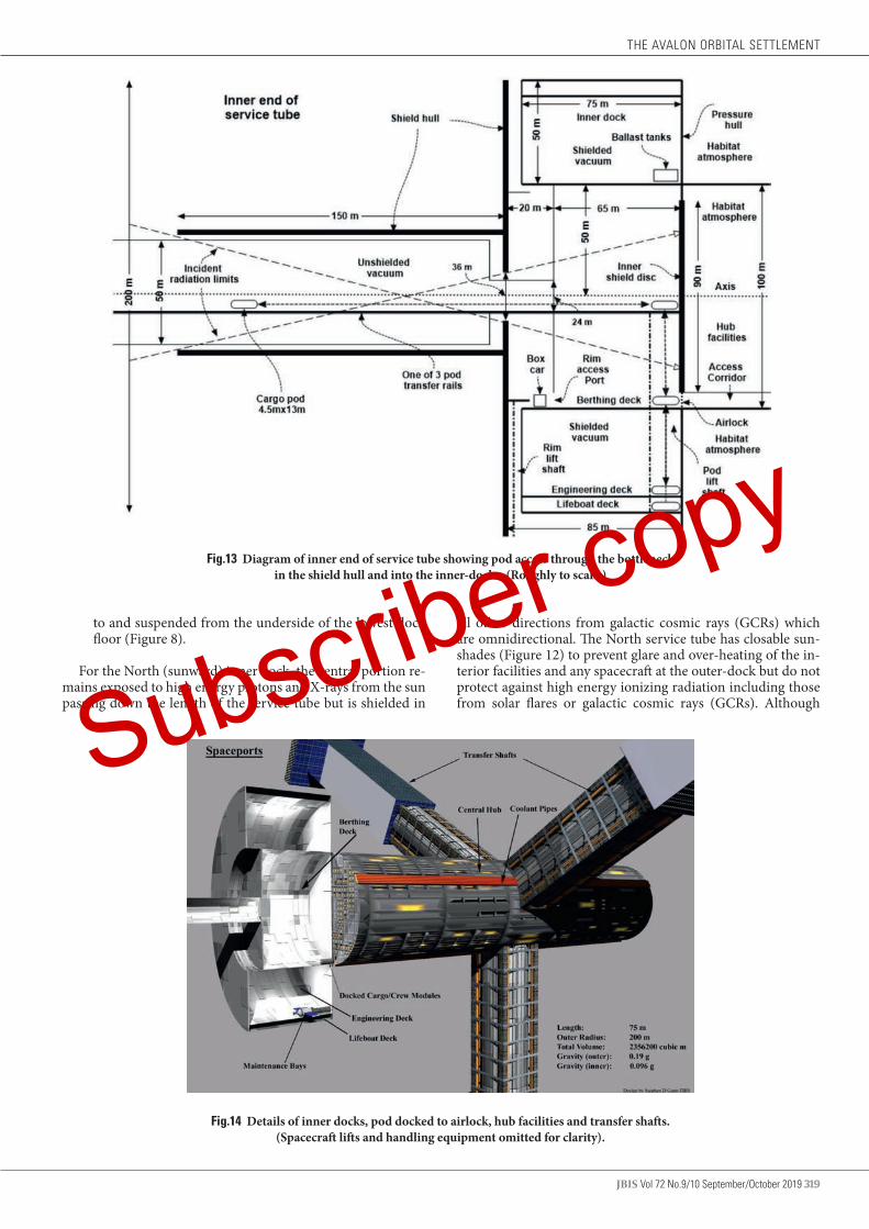
JBIS Vol 72 No.9/10 September/October 2019 319
Fig.13 Diagram of inner end of service tube showing pod access through the bottleneck in the shield hull and into the inner-docks. (Roughly to scale.)
to and suspended from the underside of the lowest dock floor (Figure 8).
For the North (sunward) inner dock, the central portion re-mains exposed to high energy protons and X-rays from the sun passing down the length of the service tube but is shielded in
all other directions from galactic cosmic rays (GCRs) which are omnidirectional. The North service tube has closable sun-shades (Figure 12) to prevent glare and over-heating of the in-terior facilities and any spacecraft at the outer-dock but do not protect against high energy ionizing radiation including those from solar flares or galactic cosmic rays (GCRs). Although
Fig.14 Details of inner docks, pod docked to airlock, hub facilities and transfer shafts. (Spacecraft lifts and handling equipment omitted for clarity).
THE AVALON ORBITAL SETTLEMENT
Subscriber copy
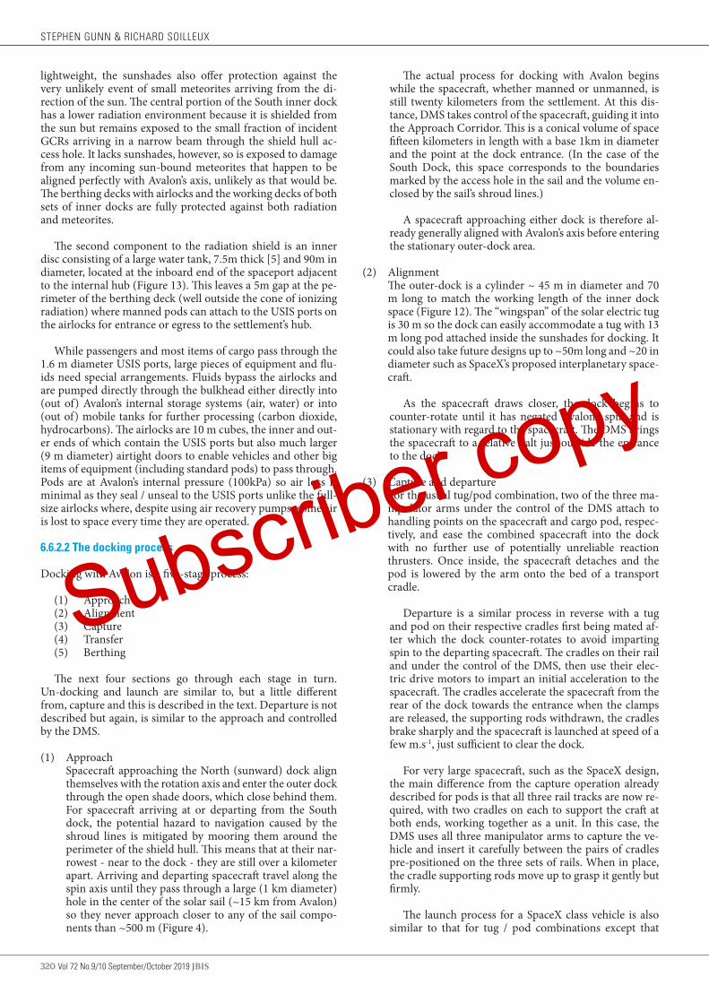
320 Vol 72 No.9/10 September/October 2019 JBIS
lightweight, the sunshades also offer protection against the very unlikely event of small meteorites arriving from the di-rection of the sun. The central portion of the South inner dock has a lower radiation environment because it is shielded from the sun but remains exposed to the small fraction of incident GCRs arriving in a narrow beam through the shield hull ac-cess hole. It lacks sunshades, however, so is exposed to damage from any incoming sun-bound meteorites that happen to be aligned perfectly with Avalon’s axis, unlikely as that would be. The berthing decks with airlocks and the working decks of both sets of inner docks are fully protected against both radiation and meteorites.
The second component to the radiation shield is an inner disc consisting of a large water tank, 7.5m thick [5] and 90m in diameter, located at the inboard end of the spaceport adjacent to the internal hub (Figure 13). This leaves a 5m gap at the pe-rimeter of the berthing deck (well outside the cone of ionizing radiation) where manned pods can attach to the USIS ports on the airlocks for entrance or egress to the settlement’s hub.
While passengers and most items of cargo pass through the 1.6 m diameter USIS ports, large pieces of equipment and flu-ids need special arrangements. Fluids bypass the airlocks and are pumped directly through the bulkhead either directly into (out of) Avalon’s internal storage systems (air, water) or into (out of) mobile tanks for further processing (carbon dioxide, hydrocarbons). The airlocks are 10 m cubes, the inner and out-er ends of which contain the USIS ports but also much larger (9 m diameter) airtight doors to enable vehicles and other big items of equipment (including standard pods) to pass through. Pods are at Avalon’s internal pressure (100kPa) so air loss is minimal as they seal / unseal to the USIS ports unlike the full-size airlocks where, despite using air recovery pumps, some air is lost to space every time they are operated.
6.6.2.2 The docking process
Docking with Avalon is a five-stage process:
(1) Approach(2) Alignment(3) Capture(4) Transfer(5) Berthing
The next four sections go through each stage in turn. Un-docking and launch are similar to, but a little different from, capture and this is described in the text. Departure is not described but again, is similar to the approach and controlled by the DMS.
(1) Approach Spacecraft approaching the North (sunward) dock align
themselves with the rotation axis and enter the outer dock through the open shade doors, which close behind them. For spacecraft arriving at or departing from the South dock, the potential hazard to navigation caused by the shroud lines is mitigated by mooring them around the perimeter of the shield hull. This means that at their nar-rowest - near to the dock - they are still over a kilometer apart. Arriving and departing spacecraft travel along the spin axis until they pass through a large (1 km diameter) hole in the center of the solar sail (~15 km from Avalon) so they never approach closer to any of the sail compo-nents than ~500 m (Figure 4).
The actual process for docking with Avalon begins while the spacecraft, whether manned or unmanned, is still twenty kilometers from the settlement. At this dis-tance, DMS takes control of the spacecraft, guiding it into the Approach Corridor. This is a conical volume of space fifteen kilometers in length with a base 1km in diameter and the point at the dock entrance. (In the case of the South Dock, this space corresponds to the boundaries marked by the access hole in the sail and the volume en-closed by the sail’s shroud lines.)
A spacecraft approaching either dock is therefore al-ready generally aligned with Avalon’s axis before entering the stationary outer-dock area.
(2) Alignment The outer-dock is a cylinder ~ 45 m in diameter and 70
m long to match the working length of the inner dock space (Figure 12). The “wingspan” of the solar electric tug is 30 m so the dock can easily accommodate a tug with 13 m long pod attached inside the sunshades for docking. It could also take future designs up to ~50m long and ~20 in diameter such as SpaceX’s proposed interplanetary space-craft.
As the spacecraft draws closer, the dock begins to counter-rotate until it has negated Avalon’s spin and is stationary with regard to the spacecraft. The DMS brings the spacecraft to a relative halt just outside the entrance to the dock.
(3) Capture and departure For the usual tug/pod combination, two of the three ma-
nipulator arms under the control of the DMS attach to handling points on the spacecraft and cargo pod, respec-tively, and ease the combined spacecraft into the dock with no further use of potentially unreliable reaction thrusters. Once inside, the spacecraft detaches and the pod is lowered by the arm onto the bed of a transport cradle.
Departure is a similar process in reverse with a tug and pod on their respective cradles first being mated af-ter which the dock counter-rotates to avoid imparting spin to the departing spacecraft. The cradles on their rail and under the control of the DMS, then use their elec-tric drive motors to impart an initial acceleration to the spacecraft. The cradles accelerate the spacecraft from the rear of the dock towards the entrance when the clamps are released, the supporting rods withdrawn, the cradles brake sharply and the spacecraft is launched at speed of a few m.s-1, just sufficient to clear the dock.
For very large spacecraft, such as the SpaceX design, the main difference from the capture operation already described for pods is that all three rail tracks are now re-quired, with two cradles on each to support the craft at both ends, working together as a unit. In this case, the DMS uses all three manipulator arms to capture the ve-hicle and insert it carefully between the pairs of cradles pre-positioned on the three sets of rails. When in place, the cradle supporting rods move up to grasp it gently but firmly.
The launch process for a SpaceX class vehicle is also similar to that for tug / pod combinations except that
STEPHEN GUNN & RICHARD SOILLEUX
Subscriber copy

JBIS Vol 72 No.9/10 September/October 2019 321
mating is not necessary and the three tracks must be used simultaneously to impart sufficient impulse for depar-ture.
After capture, a tug can either deposit its cargo pod and leave, enter the settlement (with solar panels folded) if it requires maintenance, or, more likely, dock temporar-ily onto a second cradle to refuel. (A suitable volume of fuel is transferred to tanks in the dock in advance for this scenario.) As the dock must shortly resume rotation, such a rendezvous is short term. As even unmanned tugs con-tain electronics that are vulnerable to intense radiation, any located at the North dock will need to be brought into the shielded inner-dock in the event of a SME fore-cast. If a SME is imminent approaching spacecraft are di-rected to the South dock which is shielded from the Sun by the bulk of Avalon.
After counter-rotation has been cancelled, SpaceX class vehicles can be refueled in the outer dock and un-loaded with shuttle pods used to transfer cargo and pas-sengers inside. If a SME is forecast, a SpaceX vehicle at-tached to the North dock must be moved to the shielded South dock until it is safe to leave.
(4) Transfer Once the incoming spacecraft / pod combination is se-
cured on the cradle, the dock rotation reverses to match spin with the service tube and pressure hull. When the spin is synchronized the DMS makes adjustments until the cradle’s position matches the track that connects to the appropriate pod elevator in the inner dock. In this manner, the incoming spacecraft/pod is conveyed along the service tube to the inner end, inside the shield hull but still exposed to radiation.
It will be necessary to bring the SpaceX class of space-craft inside only to carry out engineering work that can be done more easily than in the factories. Similarly, large spacecraft built in the factories mainly by robots may well be brought into Avalon’s shielded workshops for fitting out by human workers in a much safer and more accessi-ble environment. The transfer process itself is straightfor-ward with the movements of the six cradles supporting the vehicle between the rails and synchronized by the DMS moving it down the service tube and through the bottleneck when the berthing procedure takes over.
(5) Berthing After passing the bottleneck, the spacecraft / cradle en-
ters the inner-dock and continues on the rail track onto the elevator platform which is 25 m wide and 55 m long. The platforms are equipped with securing clamps and can accommodate any class of spacecraft (or other structures) that can be brought inside although most of the time they handle standard pods. The clamps are necessary because of the very low levels of pseudogravity within the dock and are especially useful to secure very large spacecraft before they start to descend and leave the embrace of the two “overhead” tracks and cradles. Like aircraft on a carri-er, the platform then lowers the pod 50 m to the berthing deck level where it is shielded and there is some gravity (~0.1 g).
Each elevator is positioned adjacent to one of the three airlocks 120° apart around the circumference where the
pod connects to the USIS berthing port [26] to access the pressurized interior via the lowest deck of the hub (Figure 13). Passenger pods are pressurized to the same level (100kPa) as Avalon so travelers can move directly through the airlocks without suffering any change in air pressure. Water and fuel tanks located below the berthing deck (called ballast tanks) and fluids are moved around the circumference as necessary to act as counter-weights to keep everything in balance (Figure 13). Between one and three pods can brought in at any one time and three can attach to airlocks but many more can be detached and moved away to be stored inside.
Spacecraft requiring maintenance and/or storage (see section 6.1) are taken by the elevator down through the berthing decks to the lowest engineering deck which con-tains large storage and workshop areas. On arrival at the engineering deck, cranes are used to lift a spacecraft off the elevator platform and move it to its designated main-tenance bay. The elevator platform is then free to return to the berthing deck and resume normal operations.
When not being used, elevator platforms are locked at berthing deck level, and the clamps withdrawn under-neath, allowing safe uncluttered movement from the air-locks out onto the deck. The radial movement of space-craft “up” and “down” marginally speeds and slows the habitat rotation rate, respectively, although this is readily corrected by the maglev system.
6.6 3 Inner dock working environment
The lower engineering deck is 75 m long and ~628 m in cir-cumference to give a working and storage floor area of ~47,000 m2 (4.7 ha). The 50 m of head space below the berthing level floor provides a working volume of ~1,600,000 m3 in vacu-um but shielded and floodlit. The detailed layout of the docks, including any requirement for additional decks, depends on unpredictable and changing requirements and has not been attempted. The North dock receives some long wavelength IR radiation via solar heating of the shield-hull end-cap oth-erwise electric radiant heaters are used as necessary to keep everything at comfortable working temperatures to facilitate safe spacecraft construction, maintenance and repair.
Much external work on spacecraft is carried out by robots where vacuum is no barrier and is even advantageous for weld-ing. Wheeled electric astronaut sortie vehicles used inside the shield hull have external manipulators to minimize, although not completely eliminate, EVA requirements which are risky and time consuming. This is because crewmembers must move between habitat pressure and much lower EVA suit or space-craft pressure. For higher pressure differentials, an extended pre-breathing protocol becomes necessary to remove absorbed nitrogen from body tissues and minimize the risk of decom-pression sickness. For example, ISS EVA operations originate from 21% oxygen and 101.3 kPa of pressure and require a 2 h pre-breathing period with pure oxygen at 70.3 kPa making frequent missions possible but inefficient and challenging. At lower total pressure, the crewmember’s lungs still must see an oxygen partial pressure similar to Earth sea- level condi-tions. The most recent recommendation for atmospheres for high frequency EVA events is to stabilize the crew at 57 kPa pressure at 34% oxygen [19], closer to suit pressure, making the pre-breathing period shorter and less risky. This makes the required percentage of oxygen in the cabin atmosphere higher
THE AVALON ORBITAL SETTLEMENT
Subscriber copy

322 Vol 72 No.9/10 September/October 2019 JBIS
than normal resulting in a somewhat higher fire risk mitigated by limiting construction materials.
Unlike passenger pods, which are maintained at full habitat pressure, sortie vehicles therefore operate at 57 kPa and have a built-in airlock to facilitate any necessary EVA operations. The sortie vehicles can be driven (either by an astronaut, teleoper-ated from within the habitat, or completely autonomously). To leave the pressurized hub, astronauts drive their vehicle with hatches open into the airlock which then becomes a decom-pression chamber. The airlock pressure is reducing slowly to 57 kPa (while the oxygen level increases to 34%) allowing time for nitrogen dissolved in the blood to dissipate. Once pre-breath-ing is complete, the vehicle is closed down before exiting the airlock then descending via a spacecraft elevator for work on the engineering deck. Separate unpressurized electric trucks carry heavy equipment and replacement parts.
Avalon does not exist in isolation but is part of an integrated materials processing and manufacturing complex [6]. Space-craft used for external missions, such as for occasional trouble shooting in the factory complex, are described elsewhere [9]. They also operate at 57 kPa and therefore require a similar exit procedure.
Passenger spacecraft are normally pressurized (100 kPa) and attached to an airlock on the berthing deck for manual internal work.
6.6.2.2 Access between hulls for inspection and maintenance
The berthing deck allows safe access between the counter ro-tating hulls for inspection and maintenance robots and, occa-sionally, workers. This needs special arrangements, however, as the relative velocity between the hulls at the rim is 104 m.s-1
(374 km.h-1) and even at berthing level it is 6.8 m.s-1 (24.5 km.h-1). Consequently, the outer safety wall is located inwards 20 m leaving an external strip of dockside deck 10 m wide all around the circumference (Figure 13). This unprotected strip overlaps, and moves counter to, a corresponding 10 m wide strip of decking attached to the inside of the shield hull end-cap at a level 1 m higher than the dockside floor. From a point on the dock side this appears as a moving platform at waist height.
Transfer between the counterrotating strips is achieved using an electric box car travelling on a rail track on the out-er edge of the berthing deck (Figure 13.). As it accelerates in an anti-spin direction (relative to the pressure hull) it begins to cancel the relative velocities between the strips until it is moving at shield hull speed. A curious feature of this arrange-ment is that during acceleration the apparent gravity deceases to zero as the pressure hull spin speed is cancelled out then builds again as the car continues to accelerate. Special wheel / rail geometry is therefore necessary to prevent a car leaving the track and everything transported, including astronauts, must be strapped down.
The operation to transfer to the shield hull begins when the tail board of a stationary box car is lowered to form a ramp for loading from the dock side. After loading, the box car acceler-ates to synchronize its speed with the rotating shield hull when its outer side hinges down to rest on the apparently unmoving platform thereby bridging the gap and allowing save transfer to the shield hull. From a passenger’s point of view, it seems exactly like a train pulling into a station allowing them to alight on the
platform. The process is reversed to return to the pressure hull.
Three elevators, located symmetrically and attached to each shield hull end–cap, enable access between berthing deck level and the inner rim. There is sufficient free space in front of the shafts to leave the loading / unloading platform free all-round the circumference.
The same vehicles used to take astronauts and equipment to and from the engineering deck are also used to access the space between the hulls. To do this they depart an airlock, cross the mezzanine floor and pass through an access port in the safety wall before transferring by accelerating box car to the shield hull. From the shield hull platform, they descend by elevator to the rim before moving out beneath the maglev tracks to inspect / maintain the drive/lev units and suspension system.
The chevron rings extend for ~35 m from the end-caps with the slots in the shield hull being ~33 m long and 3.6 m wide. The openings near the elevators are covered by glass floors to allow safe passage without blocking light. The outermost of the three maglev tracks is located a further 25 m inboard and, as they are 25 m apart, the inside edge of the maglev system is 110 m from the end-caps. The cylindrical section of shield hull between the maglev tracks is 449 m wide and 3,310 m in circumference, an area of 1,486,200 m2 (~150 ha) shielded from radiation but in hard vacuum with pseudogravity of 0.23 g. It is covered in lunar soil and rocks and makes an ideal training ground for work-ers destined for the Moon where the gravity is only a little less (~0.17 g). There is power for heating and lighting and pressur-ized emergency shelters with food and water are located strate-gically throughout for use by workers and/or trainees.
6.6.2 Hub facilities
During the construction of Avalon, the hub cylinder together with access tubes and inner docks with airlocks (Figure 10) is built first to provide a pressurized and shielded but non-rotating safe habitat for workers [9] - O’Neill’s “construction shack” [1].
Construction requires frequent EVA operations with crew-members moving between the habitat and suit or spacecraft. As described above (5.6.2.1) sortie vehicles operate at 57 kPa with 34% oxygen [19] and this pressure is also adopted for work-ers accommodation during the “construction shack” phase to eliminate the need for pre-breathing and speed up airlock transition times. There should be no problem for fit young adults living for extended periods under these conditions be-cause there are small populations of people living at or above the equivalent altitude (~4,600 m) in the Andes and Himalayas on Earth. This is especially so because the partial pressure of oxygen is ~57% lower at altitude but made up to ~100% in the construction shack. Indeed, the main physiological problem for construction workers is likely to arise from the lack of grav-ity and rigorous exercise regimes and sleeping in centrifuges are both likely to be necessary.
At this stage, the hub is not rotating so need only withstand atmospheric pressure of 57 kPa requiring a minimum cylinder wall thickness of 0.24 cm (assuming the same steel as the main hull). However, to give the safety factor of 3 considered suffi-cient during Avalon’s construction period, the wall thickness must actually be 0.71 cm.
The hub is 100 m in diameter and 446 m long and is accessed from the docks via the built-in airlocks. It contains an internal
STEPHEN GUNN & RICHARD SOILLEUX
Subscriber copy
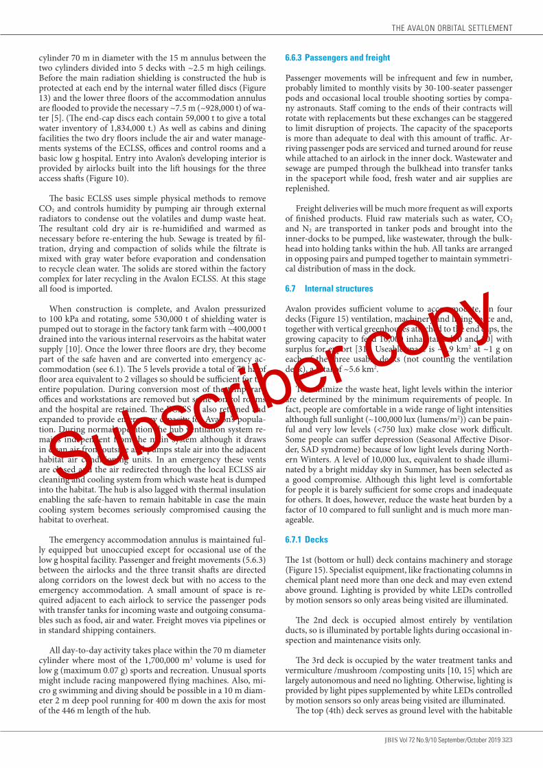
JBIS Vol 72 No.9/10 September/October 2019 323
cylinder 70 m in diameter with the 15 m annulus between the two cylinders divided into 5 decks with ~2.5 m high ceilings. Before the main radiation shielding is constructed the hub is protected at each end by the internal water filled discs (Figure 13) and the lower three floors of the accommodation annulus are flooded to provide the necessary ~7.5 m (~928,000 t) of wa-ter [5]. (The end-cap discs each contain 59,000 t to give a total water inventory of 1,834,000 t.) As well as cabins and dining facilities the two dry floors include the air and water manage-ments systems of the ECLSS, offices and control rooms and a basic low g hospital. Entry into Avalon’s developing interior is provided by airlocks built into the lift housings for the three access shafts (Figure 10).
The basic ECLSS uses simple physical methods to remove CO2 and controls humidity by pumping air through external radiators to condense out the volatiles and dump waste heat. The resultant cold dry air is re-humidified and warmed as necessary before re-entering the hub. Sewage is treated by fil-tration, drying and compaction of solids while the filtrate is mixed with gray water before evaporation and condensation to recycle clean water. The solids are stored within the factory complex for later recycling in the Avalon ECLSS. At this stage all food is imported.
When construction is complete, and Avalon pressurized to 100 kPa and rotating, some 530,000 t of shielding water is pumped out to storage in the factory tank farm with ~400,000 t drained into the various internal reservoirs as the habitat water supply [10]. Once the lower three floors are dry, they become part of the safe haven and are converted into emergency ac-commodation (see 6.1). The 5 levels provide a total of 70 ha of floor area equivalent to 2 villages so should be sufficient for the entire population. During conversion most of the temporary offices and workstations are removed but some control rooms and the hospital are retained. The ECLSS is also retained and expanded to provide emergency capacity for Avalon’s popula-tion. During normal operation the hub ventilation system re-mains independent from the main system although it draws in clean air from outside and pumps stale air into the adjacent habitat air conditioning units. In an emergency these vents are closed and the air redirected through the local ECLSS air cleaning and cooling system from which waste heat is dumped into the habitat. The hub is also lagged with thermal insulation enabling the safe-haven to remain habitable in case the main cooling system becomes seriously compromised causing the habitat to overheat.
The emergency accommodation annulus is maintained ful-ly equipped but unoccupied except for occasional use of the low g hospital facility. Passenger and freight movements (5.6.3) between the airlocks and the three transit shafts are directed along corridors on the lowest deck but with no access to the emergency accommodation. A small amount of space is re-quired adjacent to each airlock to service the passenger pods with transfer tanks for incoming waste and outgoing consuma-bles such as food, air and water. Freight moves via pipelines or in standard shipping containers.
All day-to-day activity takes place within the 70 m diameter cylinder where most of the 1,700,000 m3 volume is used for low g (maximum 0.07 g) sports and recreation. Unusual sports might include racing manpowered flying machines. Also, mi-cro g swimming and diving should be possible in a 10 m diam-eter 2 m deep pool running for 400 m down the axis for most of the 446 m length of the hub.
6.6.3 Passengers and freight
Passenger movements will be infrequent and few in number, probably limited to monthly visits by 30-100-seater passenger pods and occasional local trouble shooting sorties by compa-ny astronauts. Staff coming to the ends of their contracts will rotate with replacements but these exchanges can be staggered to limit disruption of projects. The capacity of the spaceports is more than adequate to deal with this amount of traffic. Ar-riving passenger pods are serviced and turned around for reuse while attached to an airlock in the inner dock. Wastewater and sewage are pumped through the bulkhead into transfer tanks in the spaceport while food, fresh water and air supplies are replenished.
Freight deliveries will be much more frequent as will exports of finished products. Fluid raw materials such as water, CO2 and N2 are transported in tanker pods and brought into the inner-docks to be pumped, like wastewater, through the bulk-head into holding tanks within the hub. All tanks are arranged in opposing pairs and pumped together to maintain symmetri-cal distribution of mass in the dock.
6.7 Internal structures
Avalon provides sufficient volume to accommodate, on four decks (Figure 15) ventilation, machinery and living space and, together with vertical greenhouses attached to the end caps, the growing capacity to feed 10,000 inhabitants [10 and 20] with surplus for export [31]. Useable space is ~1.9 km2 at ~1 g on each of the three usable decks (not counting the ventilation deck), a total of ~5.6 km2.
To minimize the waste heat, light levels within the interior are determined by the minimum requirements of people. In fact, people are comfortable in a wide range of light intensities although full sunlight (~100,000 lux (lumens/m2)) can be pain-ful and very low levels (<750 lux) make close work difficult. Some people can suffer depression (Seasonal Affective Disor-der, SAD syndrome) because of low light levels during North-ern Winters. A level of 10,000 lux, equivalent to shade illumi-nated by a bright midday sky in Summer, has been selected as a good compromise. Although this light level is comfortable for people it is barely sufficient for some crops and inadequate for others. It does, however, reduce the waste heat burden by a factor of 10 compared to full sunlight and is much more man-ageable.
6.7.1 Decks
The 1st (bottom or hull) deck contains machinery and storage (Figure 15). Specialist equipment, like fractionating columns in chemical plant need more than one deck and may even extend above ground. Lighting is provided by white LEDs controlled by motion sensors so only areas being visited are illuminated.
The 2nd deck is occupied almost entirely by ventilation ducts, so is illuminated by portable lights during occasional in-spection and maintenance visits only.
The 3rd deck is occupied by the water treatment tanks and vermiculture /mushroom /composting units [10, 15] which are largely autonomous and need no lighting. Otherwise, lighting is provided by light pipes supplemented by white LEDs controlled by motion sensors so only areas being visited are illuminated.
The top (4th) deck serves as ground level with the habitable
THE AVALON ORBITAL SETTLEMENT
Subscriber copy
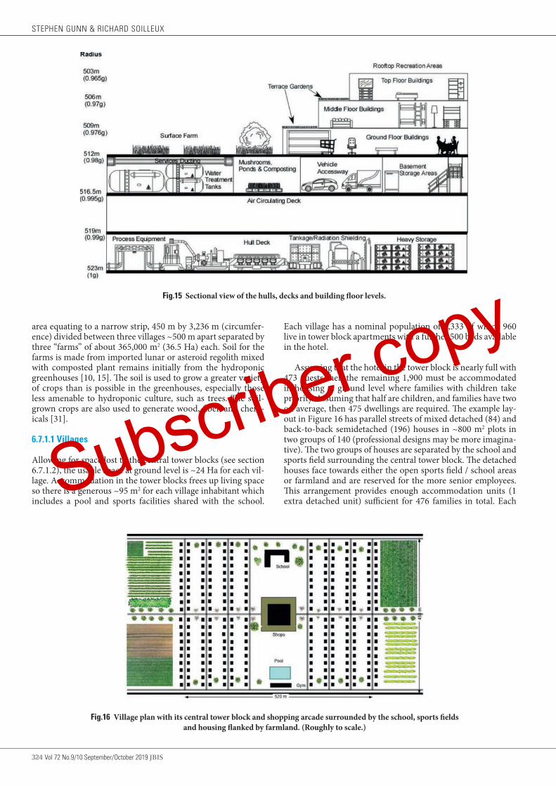
324 Vol 72 No.9/10 September/October 2019 JBIS
area equating to a narrow strip, 450 m by 3,236 m (circumfer-ence) divided between three villages ~500 m apart separated by three “farms” of about 365,000 m2 (36.5 Ha) each. Soil for the farms is made from imported lunar or asteroid regolith mixed with composted plant remains initially from the hydroponic greenhouses [10, 15]. The soil is used to grow a greater variety of crops than is possible in the greenhouses, especially those less amenable to hydroponic culture, such as trees. The soil-grown crops are also used to generate wood, fiber, and chem-icals [31].
6.7.1.1 Villages
Allowing for space lost to the central tower blocks (see section 6.7.1.2), the usable space at ground level is ~24 Ha for each vil-lage. Accommodation in the tower blocks frees up living space so there is a generous ~95 m2 for each village inhabitant which includes a pool and sports facilities shared with the school.
Fig.15 Sectional view of the hulls, decks and building floor levels.
Each village has a nominal population of 3,333 of which 960 live in tower block apartments with a further 500 beds available in the hotel.
Assuming that the hotel in the tower block is nearly full with 473 guests then the remaining 1,900 must be accommodated in housing at ground level where families with children take priority. Assuming that half are children, and families have two on average, then 475 dwellings are required. The example lay-out in Figure 16 has parallel streets of mixed detached (84) and back-to-back semidetached (196) houses in ~800 m2 plots in two groups of 140 (professional designs may be more imagina-tive). The two groups of houses are separated by the school and sports field surrounding the central tower block. The detached houses face towards either the open sports field / school areas or farmland and are reserved for the more senior employees. This arrangement provides enough accommodation units (1 extra detached unit) sufficient for 476 families in total. Each
Fig.16 Village plan with its central tower block and shopping arcade surrounded by the school, sports fields and housing flanked by farmland. (Roughly to scale.)
STEPHEN GUNN & RICHARD SOILLEUX
Subscriber copy

JBIS Vol 72 No.9/10 September/October 2019 325
4-bedroom, two story dwelling is large enough for each family to have 79 m2 of living space. This compares favorably to the average UK house with 76 m2 especially considering that no car parking or garage space is necessary and basement storage room is provided on deck 3.
Since there is no weather to contend with, buildings are of lightweight construction with flat roofs. Building materials are fireproof if possible, so walls and floors are made from opaque foamed glass panels supported by a steel frame. Bedrooms lack windows to facilitate sleeping in Avalon’s continuous daylight.
Figure 17 is an artist’s impression of the interior illustrat-ing the curved geometry of the habitat. It shows the view from above the equatorial road to a village across the intervening farmland with an orchard and wheat field. The most striking features are the central tower block and flanking end-cap green-houses. Supplementary lighting with red/blue LED grow-lights, as required for ripening some crops, results in the seemingly random pattern of pink panels. The curved lines of the “spider webs” are structural elements 30 m high while the greenhouse floors, which are 5 m apart, are not visible. The spokes are also important structures that not only support the greenhouses but also help limit the expansion of the ends of the pressure hull against the outward pressure of the concave end-caps.
The openings shown between the spokes at the bottom of the greenhouse walls give access to the animal pens, storage rooms and aquaponics units. Wide (5 m) pathways allow easy access between the buildings and to the three 10 m wide equa-torial roads. Together they provide convenient routes to the central tower block and surrounding shopping arcade which faces the sports field and gym on one side and school grounds on the other. The school swimming pool, gym, playing fields and assembly hall are available for adults to use when not re-quired for teaching but more extensive facilities are located in the tower blocks.
Some amenity space for activities such as walking or cycling is available in the farms. It is likely that the three circumferen-tial roads will prove popular with keen runners and cyclists al-
Fig.17 View from above the equatorial road across fields to a village dominated by its central tower block and flanked by the endcap greenhouses.
lowing for “laps” 3,236 m long. These also provide a convenient route for shift workers moving between the villages and farms.
An overall impression of Avalon, its location in space as well as how it might seem to a first-time visitor is given in a separate paper [32].
6.7.1.2 Tower blocks
Figure 18 is a plan view of one of the 80 m square tower blocks showing the ~53.2 m diameter cylindrical airshaft accompa-nied by lift shafts, water pipes and other utilities [20, 21] sur-rounded by the living areas. Windows are half-silvered and act as one-way mirrors to reflect light back to the growing areas while allowing the occupants to see out.
The blocks rise to 120 stories, stopping at the bottom of the window ring at approximately Martian gravity (0.41 g) while
Fig.18 Cross section of tower block showing elevator shafts and utilities attached to the airshaft and surrounded by living space.
THE AVALON ORBITAL SETTLEMENT
Subscriber copy
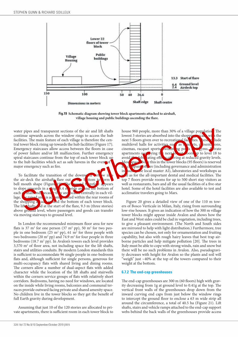
326 Vol 72 No.9/10 September/October 2019 JBIS
water pipes and transparent sections of the air and lift shafts continue upwards across the window rings to access the hub facilities. The main feature of each village is therefore the cen-tral tower block rising up towards the hub facilities (Figure 17). Emergency staircases allow access between the floors in case of power failure and/or lift malfunction. Further emergency spiral staircases continue from the top of each tower block up to the hub facilities which act as safe havens in the event of a major emergency such as fire.
To facilitate the transition of the downward airflow into the air-deck the airshafts flare out at the bottom to form a bell mouth shape (Figure 19). The ground therefore appears to slope upwards in a ring 28.4 m wide around the bottom of each airshaft and, because they are located centrally in each vil-lage, the raised area is accommodated within the rear rooms of the shopping arcade around the bottom of each tower block. The lift-shafts end at the start of the flare, 9.3 m (three stories) above ground level, where passengers and goods can transfer via moving stairways to ground level.
In London the recommended minimum floor area for new flats is 37 m2 for one person (37 m2 pp), 50 m2 for two peo-ple in one bedroom (25 m2 pp), 61 m2 for three people with two bedrooms (20 m2 pp) and 74.9 m2 for four people in three bedrooms (18.7 m2 pp). In Avalon’s towers each level provides 3,570 m2 of floor area, not including space for the lift shafts, stairs and utilities conduits. By modern London standards this is sufficient to accommodate 96 single people in one-bedroom flats and, although sufficient for single persons, generous for multi-occupancy flats with shared living and dining rooms. The corners allow a number of dual-aspect flats with added character while the location of the lift shafts and stairwells within the corners service groups of flats with relatively short corridors. Bedrooms, having no need for windows, are located on the inside while living rooms, balconies and communal ter-races provide outward facing private and shared amenity space. No children live in the tower blocks so they get the benefit of full Earth gravity during development.
Assuming that just 10 of the 120 stories are allocated to pri-vate apartments, there is sufficient room in each tower block to
Fig.19 Schematic diagram showing tower block apartments attached to airshaft, village housing and public buildings ascending the flare.
house 960 people, more than 30% of a village population. The lowest 3 stories are absorbed into the shopping arcade with the next 5 floors given over to recreational facilities. These include multilevel halls for activities such as concerts, presentations, cinemas, racquet sports, swimming pools and gyms. Private apartments occupying the next lowest floors up to level 18 to avoid the debilitating effects of living at reduced gravity levels. Most space above this in the tower blocks (95 floors) is reserved for company offices (including governance and administration including the local master AI), laboratories and workshops as well as for the all-important dental and medical facilities. The top 7 floors provide rooms for up to 500 short stay visitors as well as restaurants, bars and all the usual facilities of a five-star hotel. Some of the hotel facilities are also available to test and acclimatize travelers going to Mars.
Figure 20 gives a detailed view of one of the 110 m tow-ers of Bosco Verticale in Milan, Italy, rising from surrounding low-rise houses. It gives an indication of how the 300 m village tower blocks might appear inside Avalon and shows how the East and West sides could be clad in vegetation, including trees, to give a pleasant environment. (The North and South sides are mirrored to help with light distribution.) Furthermore, tree species can be chosen, not only for ornamentation and fruiting capability, but also with rough hairy leaves that best trap air-borne particles and help mitigate pollution [20]. The trees in Italy must be able to cope with strong winds, rain and snow but there will be no such problems in Avalon. Also, pseudogravi-ty decreases with height for Avalon so the plants and soil will “weigh” just ~40% at the top of the towers compared to their weight at the bottom.
6.7.2 The end-cap greenhouses
The end-cap greenhouses are 300 m (60 floors) high with grav-ity decreasing from 1g at ground level to 0.41g at the top. The vertical front walls of the greenhouses drop down from the inward curving end caps from just below the window rings to intercept the ground floor to enclose a 63 m wide strip all around the circumference, a total of 40.5 ha (Figure 21). Lift shafts, stairs and vehicle ramps attached to the end-cap support webs behind the back walls of the greenhouses provide access
STEPHEN GUNN & RICHARD SOILLEUX
Subscriber copy
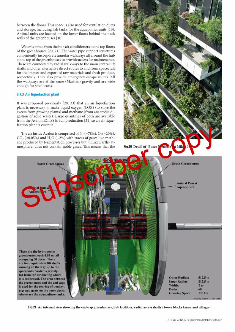
JBIS Vol 72 No.9/10 September/October 2019 327
Fig.20 Detail of “Bosco Verticale” in Milan, Italy.
between the floors. This space is also used for ventilation ducts and storage, including fish tanks for the aquaponics units [10]. Animal units are located on the lower floors behind the back walls of the greenhouses [10].
Water is piped from the hub air conditioners to the top floors of the greenhouses [20, 21]. The water pipe support structures conveniently incorporate annular walkways all around the hub at the top of the greenhouses to provide access for maintenance. These are connected by radial walkways to the main central lift shafts and offer alternative direct routes to and from spacecraft for the import and export of raw materials and fresh produce, respectively. They also provide emergency escape routes. All the walkways are at the same (Martian) gravity and are wide enough for small carts.
6.7.3 Air liquefaction plant
It was proposed previously [20, 33] that an air liquefaction plant is necessary to make liquid oxygen (LOX) (to store the excess from growing plants) and methane (from anaerobic di-gestion of solid waste). Large quantities of both are available from the Avalon ECLSS in full production [31] so an air lique-faction plant is essential.
The air inside Avalon is comprised of N2 (~78%), O2 (~20%), CO2 (<0.05%) and H2O (~2%) with traces of gases like meth-ane produced by fermentation processes but, unlike Earth’s at-mosphere, does not contain noble gases. This means that the
Fig.21 An internal view showing the end-cap greenhouses, hub facilities, radial access shafts / tower blocks farms and villages.
Subscriber copy

328 Vol 72 No.9/10 September/October 2019 JBIS
air liquefaction plant can be simpler than conventional equip-ment which needs to deal with the complication of separating the noble gases.
The plant is located in the Southern dock area to take advan-tage of constant shade and the high vacuum of space. The plant also has its own radiator system for dumping heat extracted from the air. Liquid air products are stored in tanks located symmetrically around the dock area and kept in permanent shade. They are filled and emptied in sequence under the con-trol of the plant AI to maintain a symmetrical mass balance. Surplus products are sold to visiting spacecraft to replenish their air supplies and/or exported for which the dock location for the storage tanks is convenient.
6.7.4 Air circulation, heat and water transport
Waste heat from insolation (125.56 MW) and electricity from the solar array (264 MW) is transported internally before be-ing dumped via the radiators. Air circulation mechanisms and requirements are discussed in detail elsewhere [20, 21] but the overall heat balance is shown in Table 4. This also shows that the required radiator area totals ~1.37 km2 but, because the ra-diators can shed heat from both sides, they are actually half this at 0.67 km2.
The main “housekeeping” power demand, mainly for fans, air-conditioning and lighting, has been calculated [18, 20] and is summarized in Table 5. It amounts to 83% of the 264 MW generated leaving 17% (46 MW or 4.6 kW pp), more than enough to run elevators, internal transport, other machinery as well as for personal use and some light industry.
The air circulation, heat and water transport systems feature a large cylindrical ventilation chamber, housing the air-condi-tioner units, enclosing the hub above the window ring (0.22g level). Fans in the three radial airshafts draw moist air through the air-conditioners where its temperature drops below the dew point and excess moisture condenses out. Waste heat is extracted and carried through the shield hull via the airlock/spaceport complex and dumped via the radiators. It is clear from this that the power needed to run the ventilation and cooling systems as well as limitations in the capacity if the in-ternal waste heat transport mechanisms are significant con-straints on habitat design.
TABLE 4 Overall heat input and disposal Heat Source Power (MW) Radiator (km2)
Sunlight 125.56 0.44
Electric external end cap 264.00 0.93
Total 389.56 1.37
TABLE 5 Estimated “housekeeping” power requirements Heat Source Power required
(MW)Fraction of input
power (%)
Fans & pumps 134 51
Dehumidifiers 73 28
LEDs 11 4
Not allocated 46 17
Total 264 100
The condensed water is used for irrigation and other pur-poses inside the habitat. Air blown by fans from the air deck passes though ducting to ventilate the other decks before leav-ing via grated outlets throughout both villages and farmland.
Wind friction causes a small but continuous drag on the ro-tation countered automatically by the maglev system.
7 MAJOR INCIDENTS NECESSITATING EVACUATION
One of the safety requirements identified in Section 3.1 is “A means of evacuating the entire population to the onboard hub “safe haven” and, if necessary, from there to Earth.” This drastic step would only be necessary in extreme circumstances and two scenarios where it could feasibly happen are now discussed.
7.1 Atmospheric contamination
Atmospheric contamination has the potential to make Avalon uninhabitable so represents a high level of hazard. Polluting processes that could cause high levels of contamination could be chemical or biological in origin. They could arise from a variety of sources including fire, rotting plants or chemical pol-lution [34].
7.1.1 Mitigation measure for atmospheric contamination
Personal protective equipment (PPE), such as breathing appa-ratus and/or respirators, is provided in potentially hazardous areas while safe havens exist throughout the habitat wherever people are expected. Preplanned escape routes are marked at low level with emergency lighting strips. The habitat is natural-ly divided into compartments, principally the lower decks, hub facilities and tower blocks, that can all be isolated by shutting down the ventilation systems to prevent the spread of contami-nation. Growing plants form a key part of the atmosphere wide pollution abatement system helping eliminate atmospheric contaminants so the ventilation systems of the end-cap green-houses must continue working. Fortunately, the large volume of Avalon’s atmosphere and low circulation rate [18, 20] means the spread of any contamination reaching the interior volume will be slow giving time for evacuation [34].
In addition, all habitable compartments, such as housing of-fices and other workplaces, can be temporarily sealed off giving time to evacuate people to the nearest refuge. Most of these ref-uges are temporary, however, and only suitable for minor local incidents. A major incident resulting in, for example, widespread atmospheric contamination would require evacuation to the hub facilities. These are equipped to house all 10,000 people, albeit in cramped conditions and minimal gravity. If power is avail-able then evacuation could most rapidly be achieved using the lifts in the main access shafts. Without power, however, it would be much more difficult and require a long climb up the emer-gency staircases in the tower blocks then up the spiral staircases to the hub. Alternative escape routes are up the vehicle ramps behind the end-cap greenhouses. Most people could walk with small children, the elderly and infirm being carried on trailers towed by the battery powered farm vehicles. On reaching Mar-tian gravity level at the top of the greenhouses it would be nec-essary to cross the walkways to reach the transfer shafts before making the final climb up the spiral emergency staircases to the hub. This long ~5 km journey, mostly uphill, would be hard even for fit young people but would get easier as they ascend because pseudogravity decreases with height to very low levels at the hub. Small children and infirm adults might have to be carried.
STEPHEN GUNN & RICHARD SOILLEUX
Subscriber copy

JBIS Vol 72 No.9/10 September/October 2019 329
7.2 Overheating caused by impact damage to cooling systems
Catastrophic failure of the habitat is very unlikely and the shielded double hull should prevent serious air loss. However, the external structures, solar sail, mirror rings and especially the radiators and solar power disc are much more vulnerable. An asteroid strike, or collision with a spacecraft, causing cata-strophic damage to one access tube, outer dock and attached radiator cluster, is probably the worst credible incident capa-ble of severely compromising the habitability of Avalon [34]. A sudden loss of cooling capacity would cause overheating rising to human-intolerant levels within hours. If this were to hap-pen to the Northern (sun-facing) end then the solar power disc may well also be lost making the situation even worse.
The external radiator system consists of eight separate units in two clusters of four apiece that dump waste heat to space. A single-point failure could come from damage to one of the two access-tube structures connecting the radiator clusters to the habitat, perhaps through a collision or meteorite strike. The loss of both sets of radiators to a single failure seems much less likely.
The power input to the habitat in normal working condi-tions is some 126 MW from solar insolation, and 264 MW of electrical energy from the hub solar energy farm – a total of ~390 MW. If all radiative capacity were suddenly lost, the heating of the air would be the first consequence, since the heat exchangers extract heat energy directly from the air itself. The ambient temperature in Avalon is ~25°C; a 15-degree rise would raise that temperature to the human-intolerant level. An input power of 390 MW, acting on ~500,000t of air with specif-ic heat capacity ~1000 J/kg/K, would cause a temperature rise of 15°C in ~ 5 hours. This time would be doubled in the case of the loss of just one radiator cluster rather than both if no mitigation measures are taken.
7.2.1 Mitigation measure for overheating
One radiator cluster has half the capacity of the complete sys-tem and can therefore handle 195 MW of waste heat. It also has 45% spare capacity (an additional 88MW) so has an emergency capability of 283 MW (~73% of normal capacity). If the solar input is maintained to keep plants growing and the air breath-able, there remains the capacity to extract the waste heat from 157MW of electrical power. The fans and pumps of the internal heat extraction system use 134 MW while the A/C units need 73 MW, a total of 207 MW, more than can be managed. How-ever, if the A/C units are run at 75% capacity (55MW) and the fans at 50% (67 MW) the demand is reduced to 122 MW leav-ing 35 MW (76% of normal) for other essential systems.
Unlike atmospheric contamination, overheating of the at-mosphere will also render local safe havens uninhabitable re-quiring evacuation to the insulated hub with its independent ECLSS and cooling system. Although considered very unlikely, complete loss of both main cooling systems has the potential to eventually make the hub uninhabitable and require complete evacuation of the habitat.
Mitigation measures include changing the configuration of the internal conical mirrors to become cylinders and so reflect the incoming sunlight back through the chevrons. This meas-ure alone would extend the heating time for a complete loss of cooling capacity to ~8h. The heating rate can be cut further by reducing input electrical power, mainly to the air circulation
fans which account for ~80% of the internal electricity demand. Together these two measures reduce the heat input by ~90% leaving just sufficient power ~50MW to run essential systems including emergency lighting and the lifts, essential for rapid evacuation. (The critical maglev system has its own external power supply and cooling system so need not be considered.)
These measures should extend the heating time to 2 – 3 days, plenty of time to evacuate the population to the hub safe haven which, insulated with its own cooling system and air supply, should remain habitable for many days, even weeks.
If the accident causing loss of cooling capacity occurs at the Northern dock and the solar power disc is also lost then emer-gency back-up power will become necessary urgently. Fortu-nately, Avalon is embedded in a large orbital manufacturing complex with its own independent solar power arrays inter-connected in an electricity supply grid. In addition, each elec-tricity generating plant is capable of providing beamed power to any other component of the constellation and Avalon has rectennas attached to each radiator cluster each capable of ac-cepting 250 MW of beamed power. Therefore, if the Northern rectenna array were to be lost along with the solar power disc and radiator cluster then the other could provide back-up pow-er sufficient for Avalon in emergency shut-down mode.
7.3 Means of evacuation
If the situation deteriorates sufficiently it may become neces-sary to evacuate the habitat entirely. This is a tall order but is achievable in principle because Avalon’s inner-docks have the capacity to store sufficient passenger pods as “lifeboats”. Each pod holds 30 passengers so at least 334 are needed in total.
The inner-dock is a cylinder 75 m long and 200 m diameter. Pod storage is on a special “lifeboat” deck below the engineer-ing deck and easily capable of taking five 13 m long pods in each of 70 rows arranged around the ~630 m circumference (Figure 22). This gives 350 for each dock so, in the unlikely event that one dock becomes compromised (perhaps by the same meteorite strike that compromises the cooling system and makes evacuation necessary), a single dock has the capac-ity to evacuate the entire population of 10,000. Stored pressur-ized, and with emergency supplies for a week, standard pods with their built in ECLSS become emergency lifeboats capable of docking with tugs. Pods and emergency supplies are stored in both docks to allow safe evacuation in case egress from one dock is compromised.
A warehouse style conveyer brings pods to hatches in the pod elevators which lift them to the berthing deck to be attached to the airlocks for embarkation. They are then recovered by the usual lift system to the axis conveyer then to the outer docks.
Embarkation and departure of the lifeboats is probably the main bottleneck to evacuation almost certainly taking more time than that necessary to move everyone to the hub. Assume that it takes 30 min to move each pod from the lifeboat deck to an airlock, load the passengers then move it to the outer docks. With three airlocks and associated lifts operating simul-taneously, each spaceport can evacuate 6 pods containing 180 people/h, 12 pods 360 people/h in total. At this rate it takes 28 hours to evacuate the entire population, 56 h if just one space-port is available. This should be just enough time if catastroph-ic loss of the entire cooling system makes the safe-haven but a temporary refuge.
THE AVALON ORBITAL SETTLEMENT
Subscriber copy

330 Vol 72 No.9/10 September/October 2019 JBIS
It is unlikely that there would be sufficient habitat capaci-ty to accept the refugees at L5 during the early stages of space settlement so it is assumed that they will have to be returned to LEO then Earth. It is unlikely, however, that sufficient tugs would be available locally to take the pods directly to LEO dur-ing the week before onboard supplies ran out. In this case three courses of action are available, given below in decreasing de-grees of desirability.
(1) Remain inside the hub safe haven until evacuation to Earth is arranged.
(2) Transfer to pods on the lifeboat deck using the pressur-ized maintenance vehicles. Pod supplies are then replen-ished from emergency stores as necessary.
(3) Robot tractors, normally used to transport passenger and cargo pods around the factory complex, now transfer the evacuees from the outer airlocks to pre-prepared docking stations within the factory complex where ample supplies of air and water are maintained. All available tugs are used to evacuate pregnant women and babies to the facilities in LEO to minimize their radiation exposure.
In all cases, emergency supplies of frozen food from sur-plus production stored in shade within the factory complex sustain the evacuees for many weeks, buying the time neces-sary to return them all to Earth.
8 Conclusions
A review of Gerard O’Neill’s Island 1 orbital habitat has re-vealed significant problems with the design concerned mainly
Fig.22 Shows arrangement of escape pods on the lowest, lifeboat deck, of the inner dock.
with the lack of rotational stability and insufficient radiation protection. These and other important issues have now been addressed by an extensive and detailed study that uses new de-sign principles, identifies risks and proposes mitigation meas-ures. Maximum utilization of raw materials is important, not only for reasons of economy but also to minimize the waste disposal problem. Conveniently, habitat construction utiliz-es for shielding and/or soil the otherwise waste silicates that form the bulk of many asteroids. This work has resulted in a new design for an Island 1 class orbital habitat called Avalon that avoids most of the problems with O’Neill’s original. Al-though the simplicity of a single hull is attractive and more closely follows the proposed design principles, counter rotat-ing double hulls have significant advantages. The twin hull de-sign does, however, risk catastrophic failure should they come into contact and complicates access, both problems requiring engineering solutions. Nevertheless, applying the design prin-ciples together with mitigation measures for the main risks produces Avalon – a robust, safe habitat with counter rotat-ing hulls able to support 10,000 inhabitants. It is more capa-ble than a single hull, with an expected working life of >1,000 years. In the extreme case that the habitat must be evacuated, the entire population could be accommodated in an onboard “safe haven” and, if necessary, transferred to Earth.
Acknowledgements
We wish to thank the various members of the SPACE Project team for their input as the design of Avalon has evolved over the last several years. In particular, we must thank Stephen Baxter for pointing out and helping with problem areas lead-
STEPHEN GUNN & RICHARD SOILLEUX
Subscriber copy
JBIS Vol 72 No.9/10 September/October 2019 331
ing to a much more robust design. Mark Hempsell has also been of great help with detailed discussions on various as-pects of the design. We must also thank Amelia Stanton for checking some of the calculations. We are also indebted to Samar AbdelFattah who has reviewed the critical maglev sys-
tem and her comments and recommendations have helped eliminate errors and improve the design. We also wish to thank Barbara Soilleux for her delightful water colour paint-ing which shows the striking and unusual appearance of the inside of Avalon.
1. G.K. O’Neill. The High Frontier: Human Colonies in Space, Corgi Books, 1978.
2. R. Johnson and C. Holbrow. “Space Settlements: a Design Study”, NASA SP- 413, NASA Ames Research Center, Moffett Field, CA, 1977.
3. To be published. S. Baxter. “Background to the SPACE project”. (Part of the BIS Space Project)
4. A. Globus, N. Arora, A. Bajoria and J Strout. “The Kalpana One Orbital Space Settlement Revised”. AIAA, 2007.
5. A. Globus and J. Strout. “Orbital Space Settlement Radiation Shielding”. NSS Space Settlement Journal, April 2017.
6. S.D. Gunn and R.J. Soilleux. “A rationale for developing and locating an orbital manufacturing facility utilizing extra-terrestrial materials”. JBIS Vol 72 No. 9 Sept 2019, pps 332-341
7. S. Baxter. “From the Brick Moon to Island One: Space Habitats in Science Fiction before O’Neill’s High Frontier”. JBIS Vol 72 No. 9 Sept 2019, pps 332-341.
8 S.D. Gunn and R.J Soilleux. “The Optimum Location for an Orbital Materials Processing and Manufacturing Complex (OMPMC) Utilizing Extra-terrestrial Materials”. JBIS Vol 72 No. 9 Sept 2019, pps 296-301.
9. R.J. Soilleux, “Orbital Civil Engineering: Waste Silicates Reformed Into Radiation-shielded Pressure Hulls. JBIS Vol 72 No. 7 July 2019, pps 244-252.
10. To be published: R. J. Soilleux, “Avalon’s environmental control and life support system (ECLSS) Part I”. (Part of the BIS Space Project)
11. A. Globus and T. Hall. “Space Settlement Population Rotation Tolerance”. NSS Space Settlement Journal, June 2017.
12. P. Janhunen. “Natural Illumination Solution for Rotating Space Settlements”. NSS Space Settlement Journal September 2018.
13. S. Baxter and A. Manning. “Avalon: The Governance of a Company Town”. JBIS Vol 72 No. 7 July 2019, pps 244-252.
14. ISS – operating an outpost in the New Frontier. NASA-SP-2017-634.15. R.J. Soilleux. “Towards closed environmental control and life support
for space habitats; Part II, reduced risk and increased efficiency with biological systems”. NSS Space Settlement Journal, Issue #2, February 2017–July 2017. (Part of the BIS Space Project)
16. J.S. Lewis. Asteroid Mining 101: Wealth for the New Space Economy, Deep Space Industries, 2015, ISBN 978-0-9905842-0-9
17. S.J. Pawlak. “Microstructure and properties of vacuum melted high cobalt and cobalt-free maraging steels”. Journal of Achievements in Materials and Manufacturing Engineering Volume 27 Issue 1 March 2008.
18. F. Ruess et al, “Structural Design of a Lunar Habitat,” H. DOI: 10.1061/
ASCE0893-1321200619: 313319. M.S. Anderson, M.K. Ewert and J.F. Keener. “Life Support Baseline
Values and Assumptions Document”. NASA/TP-2015–218570/REV120. S.D. Gunn and R.J Soilleux. “Environmental Control and Life Support
(ECLSS) for Large Orbital Habitats: Ventilation for Heat and Water Transport and Management. NSS Space Settlement Journal, Issue #3, November 2017–September 2018. (Part of the BIS Space Project)
21. To be published, S.D Gunn and R.J. Soilleux. “Avalon ECLSS Part II. Ventilation for water and heat flow and management”. (Part of the BIS Space Project)
22. To be published, S.D. Gunn, “Attitude Control and Orbital Adjustment of Avalon using Solar Sail Technology”. (Part of the BIS Space Project)
23. O. Tozoni. “Self-regulating magneto-dynamic system for high speed ground transportation vehicle”. US 8047138. Pub. 2011.
24. R.F. Post and D.D. Ryutov. “The Inductrack Approach to Magnetic Levitation”. MAGLEV 2000, The 16th International Conference on Magnetically Levitated Systems and Linear Drives, Rio de Janeiro, Brazil, June 6-11, 2000.
25. R.F. Post and L. Nguyen. “The Design of Halbach Arrays for Inductrack Maglev Systems”. 2008. 20th International Conference on Magnetically Levitated Systems and Linear Drives, December 16-18, San Diego, CA
26. M. Hempsell. “Creating a Universal Space Interface Standard”, JBIS, Vol 69 2016, pps 163-174.
27. To be published: S.D. Gunn. “Avalon: hospitals and medical support”.(Part of the BIS Space Project)
28. M. Hempsell. “Scorpion; a design study for a general-purpose space transportation system”. JBIS Vol 72 No. 7 July 2019, pps 350-354.
29. M. Hempsell. “Docking with rotating space systems”. JBIS Vol 72 No. 5 May 2019, pps 153-160.
30. Martin Schweiger’s open source Orbiter Space Simulation software hosted by UCL, Dept. Med Phys. Copywrite, Martin Schweiger 2000 0 2016. http://orbit.medphys.ucl.ac.uk
31. To be published: R.J. Soilleux. “Avalon ECLSS Part III, Surplus capacity used to generate soil, wood, fiber, and chemicals”. (Part of the BIS Space Project).
32. S Baxter. “Avalon: A Tour of the Settlement”. JBIS Vol 72 No. 9 Sept 2019, pps 350-354.
33. R.J. Soilleux. “Towards closed environmental control and life support for space habitats. Part I, a basic system. NSS Space Settlement Journal, Issue #2, February 2017–July 2017. (Part of the BIS Space Project).
34. To be published: R.J. Soilleux. “Avalon Risk Assessment and Management”. (Part of the BIS Space Project).
REFERENCES
Received 16 July 2019 Approved 3 December 2019
THE AVALON ORBITAL SETTLEMENT
Subscriber copy
332 Vol 72 No.9/10 September/October 2019 JBIS
A RATIONALE FOR DEVELOPING AN ORBITAL MATERIALS PROCESSING AND MANUFACTURING COMPLEX (OMPMC) Utilizing Extra-terrestrial Materials STEPHEN D. GUNN1, FBIS & RICHARD J. SOILLEUX2, 114, Hillsboro Road, Bognor Regis, West Sussex, PO21 2DX UK; 23, Kings Paddock, West Winterslow, Salisbury, Wilts. SP5 1RZ UK
email [email protected] / [email protected]
Orbital development is expected to evolve from the ISS into tourist hotels then 1st generation orbital manufacturing with spacecraft refuelling, repair and assembly in LEO. Eventually, crippling launch costs will make 2nd generation facilities utilizing extra-terrestrial materials economically attractive. The best location for an orbital materials processing and manufacturing complex (OMPMC) is reported elsewhere and O’Neill’s proposed locations of either the L4/L5 libration points or an unspecified HEO confirmed. However, a final choice must await detailed studies using high-fidelity ephemeris models. Nevertheless, economic, power and safety demands point clearly to a location in HEO beyond the protection of Earth’s magnetic field and drives orbital settlement beyond LEO. Utilizing extra-terrestrial resources, semi-autonomous factories could build large space borne structures at little cost to Earth but with great benefit to an orbital economy. Bennu, the B-type target NEA of the OSIRIS-REx sample retrieval mission could provide raw materials and modelling for returning material to L5 shows a significantly reduced (halved) fuel requirement using an Earth flyby and optimizing return trajectories. A 3rd generation OMPMC co-located with its source NEA eliminates shipping costs for raw materials and, by restricting traffic to Earth encounters minimizes transport time/cost for finished products and people. Many NEAs approach Mars orbit so a redundant accompanying habitat could become a Mars / Earth cycler for transporting many passengers between the planets in comfort and safety. Similarly, deep space capable habitats could open up the solar system to human exploration, exploitation and habitation. Keywords: Extra-terrestrial resources, Near-Earth Asteroids, NEAs, Orbital Materials Processing and Manufacturing, L1, L2, L3, L4, L5, Lagrange libration points, GK O’Neill, Station-keeping, Solar sails.
1 SCOPE
This paper is part of the “BIS SPACE Project” revisiting O’Neill’s design for Island 1 orbital habitat [1,2] as part of an orbital ma-terials processing and manufacturing complex (OMPMC). It begins by outlining a possible near-term path for space devel-opment before examining the future necessity for an OMPMC, what it would consist of and how it might develop. This is fol-lowed by a brief outline of the competing requirements for its location although detailed arguments concerning the best orbit are given elsewhere [17]. Finally, the effect of orbital dynam-ics on fuel costs for importing raw materials from a candidate NEA is studied with a worked example.
2 INTRODUCTION
O’Neill’s work in the 1970s [1, 2] came to the surprising con-clusion that the best place for an expanding technological civ-ilisation was not the surface of a planet but rather a location in space to take advantage of abundant solar energy and con-struction materials. Further significant advantages of an orbit-al location were the ease and relative low cost of transporting enormous quantities of raw materials and of building and ma-nipulating very large and massive structures.
It was proposed that the answer to the looming energy crisis
JBIS VOLUME 72 2019 PAGES 332–341
NOMENCLATURE ARM Asteroid Redirect MissionCRTBP Circular Restricted Three Body ProblemDRO Distant Retrograde OrbitELEO Equatorial Low Earth OrbitELO Elliptical Lunar OrbitsFLO Frozen Lunar OrbitGEO Geostationary Earth OrbitHEO High Earth OrbitISS International Space StationLEO Low Earth OrbitLLO Low Lunar OrbitsLOP-G Lunar Orbital Platform-GatewayNEA Near-Earth AsteroidNRHO Near Rectilinear Halo OrbitOMPMC Orbital Materials Processing and Manufacturing
ComplexPCO Prograde Circular Orbits
Subscriber copy

JBIS Vol 72 No.9/10 September/October 2019 333
at that time was space based solar power generated on huge satellites and beamed down to receivers (rectifying antennas or rectennas) on Earth [1]. This necessitated space manufactur-ing to construct the power satellites largely from lunar material which, even with the reduction in launch costs expected from the Space Shuttle, would be much cheaper than taking them from Earth.
Manufacturing methods during the 1970s needed a substan-tial human workforce so the early proposals planned for large numbers of workers to build the very big satellites thought nec-essary for solar power. A manned lunar base was also thought necessary for the mining operation as well as to facilitate construction and operation of electromagnetic mass-drivers launching raw material into orbit. Construction was to take place in orbit so large rotating orbital habitats were proposed as safe, comfortable homes for the factory workers. The construc-tion site was to be located away from Earth but near the Moon for easy access to the enormous amounts of lunar materials re-quired, mainly for radiation shielding. It was consequently to be located first at L4/L5 but later in an unspecified high Earth orbit (HEO) when orbital stability problems were discovered at the libration points [3].
3 A POSSIBLE NEAR FUTURE PATH FOR SPACE DEVELOP-MENT AND A RATIONALE FOR DEVELOPING AN OMPMC
3.1 First steps
Industrial development in space is likely to evolve slowly build-ing on experience with the International Space Station (ISS) [4, 5, 6]. Next will come other research facilities and space ho-tels in Low Earth Orbit (LEO). If these are kept below about 500 km little or no radiation shielding is required [4, 5, 7] with great benefit to the mass budget. Constructed entirely with ma-terials from Earth with the expected reduction in launch costs from the re-usable vehicles currently under development they will remain expensive but affordable [4, 5].
The economics of trading with Earth are doubtful except for tourism and zero/low gravity sports, which are likely to be major sources of revenue for any commercial orbital habitat. However, universities on Earth may choose to rent pre-existing orbital accommodation for research purposes.
An established orbital hotel construction, maintenance and repair capability will almost certainly diversify to build and ser-vice other types of satellite [6] – in particular, large telescopes, communications and solar power satellites [8] that could not be built and/or launched from Earth. This would be a 1st gen-eration facility. It may also prove advantageous to manufacture high value products such as drugs and superior optical fibres in the micro-g high vacuum orbital environment.
In time, an expanding industry in LEO may become con-strained by the intermittent power supply and high launch costs for construction materials and consumables from Earth. This will drive a need to exploit potentially cheaper extra-ter-restrial resources [9,10] using a 2nd generation facility. (This problem may become urgent sooner than expected because the geomagnetic field seems to be collapsing, as it has many times in the deep past [11]. If this happens, the cost of space settlement in LEO will increase substantially because of the need for radiation shielding. However, the higher radiation en-vironment may not necessarily be a problem for short trips by researchers and tourists.)
3.2 Likely impact of current and emerging technologies on the development of orbital materials processing and manufacturing
Earth’s mining industries are in transition to a largely automat-ed future with remote human oversight. However, machines break down and human workers remain necessary for repair and maintenance. NEAs are the best source of extra-terrestrial materials [10] but the lack of any present and near-term ca-pability for manned deep space missions means that a human presence at any minable asteroid can be discounted at present. Sophisticated mining methods are therefore not feasible but robotic methods for capturing small asteroids, or removing material from rubble pile asteroids, are almost within current capabilities [12].
It is therefore probable that automated methods will be used to recover raw materials without any attempt at benefi-ciation and all processing, refining and manufacture carried out at a largely autonomous orbital facility. (The one excep-tion might be the extraction of reaction mass for the return journey.)
The new automated mining methods are paralleled by sim-ilar developments in manufacturing with computer-controlled machines working to 3D CAD designs giving great flexibility and making small production runs economical. The advent of additive manufacturing, or 3D printing, is accelerating this trend and affordable production of single items is now routine. Its versatility and efficient use of materials makes 3D printing ideal for making a wide range of (often one-off) structures in space and it is likely to become an important manufacturing technique. Artificial Intelligence (AI) and manipulator robots capable of overseeing and managing such a complex operation are still some way off [13] so direct human presence is likely to be necessary for the near to medium term.
A largely automated OMPMC with a small highly skilled human workforce like a modern car plant is probably a pre-requisite for large-scale space construction. Automated orbital factories using free solar energy and cheap raw materials effi-ciently, working continuously with relatively few highly paid workers change the whole concept of cost. After start-up costs to build and launch the first equipment and provide high tech components and equipment (until they can be made in space), costs would fall dramatically while capability grew. Further-more, an established OMPMC, which includes humans to provide oversight and high-level decision making and repair capabilities, should be capable of self-replication and have no practical limit to production capacity.
Significantly, once the first orbital habitat has been con-structed there is no substantive reason why many more should not follow, driven partly by the continuing need to utilize slag from smelting metals required for other construction projects. At this stage, the OMPMC would enter the real estate business creating and selling ever more orbital living space providing a significant new revenue stream.
Precious metals will be a by-product of ferrous metal ex-traction and separation (by the Mond carbonyl process), some used in orbit but most marketed on Earth [10]. Together with specialist items manufactured in microgravity, such as supe-rior fibre optic cables, these will provide return payloads for re-useable cargo pods, and perhaps passenger spaceplanes such as Skylon, servicing LEO facilities.
A RATIONALE FOR AN ORBITAL MATERIALS PROCESSING AND MANUFACTURING COMPLEX (OMPMC) Utilizing Extra-terrestrial Materials
Subscriber copy

334 Vol 72 No.9/10 September/October 2019 JBIS
3.3 Components of an orbital industrial complex
An orbital industrial complex might initially contain a receiv-ing station for raw materials, small habitat, power sat, materials processing facility, plant for volatiles separation and tank farm for storage. Even the simplest orbital construction requires a framework, or jig, to hold equipment and components in their correct positions and prevent drift during assembly. Such an ensemble is termed a jig-factory [concept credit John Strick-land, NSS] and provides all necessary scaffolding and reference supports for construction. Importantly, it also enables cheap and efficient transport of massive components and equipment around the construction site using rails and electric motors rather than fuel hungry rocket motors.
A mature factory complex might also include storage “barns” and tank farm plus at least one metal smelter, factory for making small items and a jig-factory for large structures. All these components must be co-located and managed so that they can work efficiently together.
The amount of electric power required for a mature orbital industrial complex is difficult to estimate without an analysis of the necessary processes and the quantities and types of ma-terial being produced. Nevertheless, a rough figure has been obtained by using the mass and materials required to construct an O’Neill Island 1 class orbital settlement for 10,000 people [14]. It has consequently been estimated that ~1.7 GW would be needed for the construction and, if all power is electric, re-quires a 1.2 km radius disc of solar cells (assuming 29% effi-ciency).
3.4 Options for locating the OMPMC
As already discussed, the early development of space tour-ism and manufacturing will probably occur in LEO. Due to the need to minimize launch costs by using the Earth’s own rotation to boost velocity most industrial facilities will be in or near equatorial low Earth orbit (ELEO), which also has the advantage of a relatively low radiation environment [4, 5, 7]. (Despite the extra radiation of higher inclination, tourist hotels will probably follow similar orbits to the ISS so they can pass over the home countries of paying customers [5]. There is little problem in this for short-stay tourists but staff time in orbit will need to be controlled to keep lifetime radiation exposures within safe limits.)
Locating the OMPMC in ELEO would present major diffi-culties, however.
• Spacecraft in LEO (like the ISS) must be boosted periodi-cally to prevent orbital decay.
• Half of each orbit is in Earth’s shadow with a commensu-rate impact on solar input. Low polar orbits avoid this but the huge velocity change required (11,000 m.s-1 for a 90° shift in inclination from ELEO) is prohibitively expensive.
• The risks (perceived or real) of bringing very large masses of raw materials into ELEO for processing will be unac-ceptable.
The OMPMC should, however, be as close to Earth as pos-sible to facilitate communications with the customer base in LEO and to minimize worker radiation exposure. There is a trade-off between time and energy cost from LEO and energy cost for raw materials from the Moon and/or NEAs. The vari-ous orbit requirements are summarized below and will domi-nate the location of any 2nd generation OMPMC.
1. Low enough for minimum transit times to Earth and LEO resulting in lower radiation exposure in unshielded shuttles. (Good for employees and tourists.)
2. Low enough for minimum transport energy costs for passengers (and high-tech equipment) to and from Earth and LEO. (Good for business and tourists.)
3. Low enough to be fully integrated into the WWW. (Good for business, employees, tourists and, perhaps, telemedi-cine.)
4. Low enough for medical evacuation to Earth including (in principle) the entire population in case of catastroph-ic failure of the habitat.
5. High enough to avoid perceived risks of collision from imported raw materials.
6. High enough for low transport costs for raw materials from the Moon and/or NEAs.
7. Low enough for minimum transport costs for finished products destined for both high and low orbits.
8. High enough to minimize eclipse times and temporary power loss.
9. High enough for an R&D base. (Good for researchers.)
These factors combined suggest equatorial HEO for the OMPMC not only to minimize transport costs for bulk mate-rials but also for safety reasons and to escape the power limi-tation of ELEO, which is shaded for almost half of each orbit.
Factories on Earth and LEO must initially provide the con-struction capability to build the facility in HEO, which starts small with basic materials processing for fuel, air and water and some construction materials. The eventual need for main-tenance and repair workers co-located with the manufacturing facility provides an economic driver for orbital space habitats in HEO outside the protection of Earth’s magnetic field. Even-tually, the construction of spacecraft and habitats in HEO using extra-terrestrial materials should compete favourably on cost with prefabrication and launch from Earth.
All likely candidate orbits have advantages and disadvantag-es explored in a separate paper [18]. Unfortunately, it has not proved possible to narrow the choice down to a single orbit, or class of orbits, for the first OMPMC. Indeed, it is unlikely that a final choice will be made until detailed studies are carried out using high-fidelity ephemeris models. It is possible that such studies would reveal unexpected advantages and/or disadvan-tages for some of the proposed orbits or even discover attrac-tive new orbital classes.
Following O’Neill, L5 will be used here and in associated papers and studies to designate the location with the under-standing that it is shorthand for the candidate special cases of HEO, L4/L5 and L3 Earth/Moon libration points and a 70,000 km DRO [17] unless they need to be specified for specific pur-poses.
3.6 Management of the orbiting components
The station keeping cost for a group of satellites has not been estimated although it cannot be equal to the sum of the indi-vidual costs because of instabilities [17, 18]. Significantly, a likely fuel saving strategy will allow spacecraft orbits to evolve according to the natural orbital dynamics without attempting to constrain them close to an arbitrary norm [17]. Consequent-ly, a group of space-craft would soon drift apart into different orbits and it would clearly not be economical to use the avail-able station keeping methods [14] to keep them together. Even
STEPHEN GUNN & RICHARD SOILLEUX
Subscriber copy
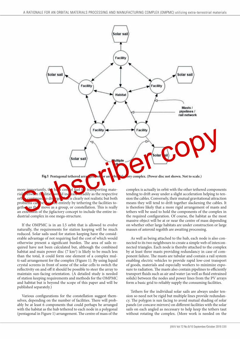
JBIS Vol 72 No.9/10 September/October 2019 335
more importantly, the high cost of fuel for transporting mate-rials between facilities would increase steadily as the respective orbits continued to diverge. This is clearly not realistic but both problems can be avoided entirely by tethering the facilities to-gether so they move as a group, or constellation. This is really an extension of the jigfactory concept to include the entire in-dustrial complex in one mega-structure.
If the OMPMC is in an L5 orbit that is allowed to evolve naturally, the requirements for station keeping will be much reduced. Solar sails used for station keeping have the consid-erable advantage of not requiring fuel the cost of which would otherwise present a significant burden. The area of sails re-quired have not been calculated but, although the combined habitat and main power disc (7 km2) is likely to be much less than the total, it could form one element of a complex mul-ti-sail arrangement for the complex (Figure 1). By using liquid crystal screens in front of some of the solar cells to switch the reflectivity on and off it should be possible to steer the array to maintain sun-facing orientation. (A detailed study is needed of station keeping requirements and methods for the OMPMC and habitat but is beyond the scope of this paper and will be published separately.)
Various configurations for the constellation suggest them-selves, depending on the number of facilities. There will prob-ably be at least 6 components that could perhaps be arranged with the habitat as the hub tethered to each node in a polygonal (pentagonal in Figure 1) arrangement. The centre of mass of the
Fig.1 Pentagonal tethered arrangement for an orbital factory complex. (Power disc not shown. Not to scale.)
complex is actually in orbit with the other tethered components tending to drift away under a slight acceleration helping to ten-sion the cables. Conversely, their mutual gravitational attraction means they will tend to drift together slackening the cables. It is therefore likely that a more rigid arrangement of masts and tethers will be used to hold the components of the complex in the required configuration. Of course, the habitat as the most massive object will be at or near the centre of mass depending on whether other large habitats are under construction or large masses of asteroid regolith are awaiting processing.
As well as being attached to the hub, each node is also con-nected to its two neighbours to create a simple web of intercon-nected triangles. Each node is thereby attached to the complex by at least three masts providing redundancy in case of com-ponent failure. The masts are tubular and contain a rail system enabling electric vehicles to provide rapid low-cost transport of goods, materials and especially workers to minimize expo-sure to radiation. The masts also contain pipelines to efficiently transport fluids such as air and water (as well as fluid entrained solids) between the nodes and power lines from the PV arrays form a basic grid to reliably supply the consuming facilities.
Tethers for the individual solar sails are always under ten-sion so need not be rigid but multiple lines provide redundan-cy. The polygon is sun facing to avoid mutual shading of solar panels (or concave mirrors) on different facilities with the solar sails on each angled as necessary to help keep the tethers taut without rotating the complex. (More work is needed on the
A RATIONALE FOR AN ORBITAL MATERIALS PROCESSING AND MANUFACTURING COMPLEX (OMPMC) utilizing extra-terrestrial materials
Subscriber copy

336 Vol 72 No.9/10 September/October 2019 JBIS
best arrangement for the solar sails and will be included in the detailed study.) A non-rotating complex avoids difficulties for docking and problems with precession and will almost certain-ly be necessary.
Radiation pressure on the megastructure will be significant so the sun facing power array should be radially symmetrical (probably a disc) to avoid twisting it out of alignment. The hab-it [14] is ~ 700 m in radius (including its own built in power disc surrounded by mirror rings) and is conveniently located at the centre of the support framework. To allow space for main-tenance spacecraft to crawl around the habitat, the surround-ing main power annulus might then require an inner radius of 1 km. A 1.5 km outer radius then gives the required area of ~4 km2. The factory components could be attached around the edge of this disc to allow the concave mirrors of solar fur-naces to be outside the disc in permanent sunlight. (Significant use of direct solar heating would of course reduce the size of the PV array accordingly.) Outward facing radiators for waste heat could be placed in their shade. Similarly, tank-farms for processed volatiles, and especially, cryo-fuels, could be located behind the power disc in permanent shade.
4 ENERGY INTERVALS BETWEEN LIKELY SOURCES OF RAW MATERIALS
It is instructive to consider the energy requirements for travel to and from the likely sources of raw materials. Figure 2 shows the various velocity changes for travel between the closer of the different options.
As already discussed, the majority of industry can be expect-ed to be located within the environs of the Earth/Moon system, 1st generation construction and repair in ELEO then later 2nd generation at L5 for materials processing and construction us-ing extra-terrestrial resources.
Raw materials from the moon to L5 require a Δv of 700 m.s-1 from lunar orbit, and 2,200 ms-1 from the lunar surface. Since most of the construction mass could be from the Moon (2,900 m.s-1) only volatiles must come from further afield. It is estimated [1] that the energy interval required to reach the construction complex at L5 from the asteroid belt is typically 10,000 m.s-1 just a little less than the 12,700 m.s-1 required from Earth’s surface.
Therefore, in energy terms, there is little advantage in bring-ing material from main belt asteroids compared with importing them from Earth. However, in space high thrusts are not re-quired so spacecraft structures capable of withstanding the high accelerations and aerodynamic forces of a launch into LEO are unnecessary. Furthermore, payloads are not restricted by the need to fit within aerodynamic fairings so, provided that they are symmetrical about the thrust axis, can be almost any shape or size. There is also the issue of the environmental damage caused by the huge number of launches necessary. For exam-ple, the ~300 kt of nitrogen necessary for the atmosphere of just one Island 1 habitat [14] would require ~2,300 launches of the proposed NASA SLS Block 2 (payload 130 t). If all construction materials and consumables come from extra-terrestrial sources then transport to and from LEO will only be necessary for peo-ple, high tech equipment and luxury goods.
Furthermore, the main belt asteroids are not the only source of raw materials since the Trojan and Amor asteroids orbit much closer to Earth. Even more tempting are NEAs some of
which have orbits crossing the Earth’s (some may even pose an existential threat). These “low hanging fruit” are much easier, and therefore cheaper to exploit while simultaneously remov-ing a potential major hazard [10]. Several NEAs are known for which the total Δv for rendezvous from LEO is 4,500 m.s-1 and several hundred require less than 5,600 m.s-1 [10] only a little more than to L5 from LEO. From L5 access to NEAs is even easier because it is already most of the way out of the Earth’s gravity well leaving a required residual ΔV of 300 – 1,500 m.s-1 to change orbit. Returning material to L5 is easier still because the very low gravity of asteroids requires a Δv of <100 m.s-1 to escape their influence [10], just 3.4% of that from the lunar surface.
These data are very encouraging because much more mass in raw materials will be returned to the manufacturing facility than sent out to the NEA as extraction machinery, containers and propulsion units (tugs). Furthermore, if fuel / reaction mass can be extracted from the NEA in-situ then that required for the return journey need not be sent out on the less econom-ical leg. If all construction materials and consumables are from NEAs then lunar surface mining facilities and mass drivers to launch material into orbit become unnecessary.
4.1 Raw materials required for major construction projects
The high value of volatiles, especially during the early stages of industrialization, points towards carbonaceous chondrites as being the most desirable type of target asteroid. For these, the total inventory of extractable volatiles can exceed 46% plus 19% iron/nickel alloy with the remaining 35% complex silicates [10, p. 1993)]. The high proportion of silicates would be waste for disposal unless they could provide the large masses neces-sary for radiation protection [1, 5, 10].
Bearing this in mind large scale orbital construction should follow the important principle of maximum utilization of im-
Fig.2 Velocity changes between orbits of interest. (Not to scale.)
STEPHEN GUNN & RICHARD SOILLEUX
Subscriber copy

JBIS Vol 72 No.9/10 September/October 2019 337
A RATIONALE FOR AN ORBITAL MATERIALS PROCESSING AND MANUFACTURING COMPLEX (OMPMC) utilizing extra-terrestrial materials
ported raw materials with the main materials therefore being silicates and nickel/iron alloy. The following example is based on the quantities to build a large O’Neill Island 1 class habitat [14] of a mature OMPMC. Table 1 shows that to obtain the nec-essary 20,000 kt of nickel/iron would require 106,000 kt from a carbonaceous asteroid of the above composition while 123,000 kt would yield the necessary 43,000 kt of silicates (glass). Fur-thermore, carbonaceous chondrites contain ample quantities of water and carbon and, most importantly, about 0.25% of ni-trogen [10, p 2042].
Each 1 t of asteroid therefore contains 2.5 kg of nitrogen and 120,000 kt the 300 kt necessary to make the habitat’s air (Table 1). Conveniently, therefore, the amount of asteroid ma-terial necessary for the radiation shield would also yield more than enough nickel/iron (with a surplus of ~3,000 kt for other purposes) plus large quantities of volatiles including sufficient nitrogen for the atmosphere.
4.2 Required quantities of carbonaceous asteroid
Quantities of raw materials required during the early stages will necessarily be small and demand satisfied easily by occasional deliveries. The technology for this is almost within current ca-pabilities [12] and will almost certainly become available when necessary. In essence, the method involves sending a spacecraft to the NEA, extracting a manageable quantity and returning it to L5 using the engines to both insert the package into the return orbit and rendezvous with the receiving station.
TABLE 1 Quantities of asteroid regolith required for the main construction materials for an O’Neill Island 1 class habitat [15]Starting material Regolith (kt) Construction material Product (kt)
Asteroid iron 106,000 Steel 20,000
Waste silicates 123,000 Glass 43,000
Ices 120,000 Atmospheric nitrogen 300
A receiving station for inbound raw materials together with the associated materials processing facility would necessarily be built first with the initial products of water, fuel and air be-ing exported to the existing facilities in LEO. The next stage of development would utilize the iron and silicates accumulating as low volatility “waste” to provide construction materials for spacecraft and habitats [14].
Although the L5 complex would be largely autonomous it would be necessary for workers to make occasional mainte-nance and repair visits from LEO following a rapid (~3 days) path to minimize radiation exposure. As materials processing and spacecraft construction operations become more complex, more frequent human intervention would probably become necessary until eventually a small, shielded habitat for longer-term occupation is economical.
As industry at L5 expands, the raw materials demand will increase in proportion. This can be expected to eventually be-come very large indeed and require methods for transporting commensurately large amounts of raw materials to feed the furnaces.
Using the data in Table 1 as an example, some 120,000 kt (in round numbers) of raw materials are required and, assuming a density of 2.5 [19], this equates to a carbonaceous chondrite NEA 450 m in diameter. About 4,000 NEAs have been discov-ered in this size range as of January 2018 (Figure 3) but little is known about the composition of most.
Fig.3 Numbers of NEAs discovered as of Jan 2018.
NAS
ASubscriber copy
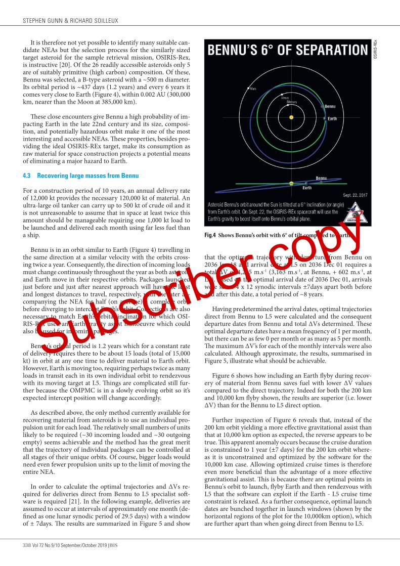
338 Vol 72 No.9/10 September/October 2019 JBIS
It is therefore not yet possible to identify many suitable can-didate NEAs but the selection process for the similarly sized target asteroid for the sample retrieval mission, OSIRIS-Rex, is instructive [20]. Of the 26 readily accessible asteroids only 5 are of suitably primitive (high carbon) composition. Of these, Bennu was selected, a B-type asteroid with a ~500 m diameter. Its orbital period is ~437 days (1.2 years) and every 6 years it comes very close to Earth (Figure 4), within 0.002 AU (300,000 km, nearer than the Moon at 385,000 km).
These close encounters give Bennu a high probability of im-pacting Earth in the late 22nd century and its size, composi-tion, and potentially hazardous orbit make it one of the most interesting and accessible NEAs. These properties, besides pro-viding the ideal OSIRIS-REx target, make its consumption as raw material for space construction projects a potential means of eliminating a major hazard to Earth.
4.3 Recovering large masses from Bennu
For a construction period of 10 years, an annual delivery rate of 12,000 kt provides the necessary 120,000 kt of material. An ultra-large oil tanker can carry up to 500 kt of crude oil and it is not unreasonable to assume that in space at least twice this amount should be manageable requiring one 1,000 kt load to be launched and delivered each month using far less fuel than a ship.
Bennu is in an orbit similar to Earth (Figure 4) travelling in the same direction at a similar velocity with the orbits cross-ing twice a year. Consequently, the direction of incoming loads must change continuously throughout the year as both asteroid and Earth move in their respective orbits. Packages launched just before and just after nearest approach will have the least and longest distances to travel, respectively, with the later ac-companying the NEA for half (on average) a complete orbit before diverging to intercept Earth’s orbit. Corrections are also necessary to match Earth’s orbital inclination for which OSI-RIS-Rex used an Earth gravity assist manoeuvre which could also be used for incoming packages.
Bennu’s orbital period is 1.2 years which for a constant rate of delivery requires there to be about 15 loads (total of 15,000 kt) in orbit at any one time to deliver material to Earth orbit. However, Earth is moving too, requiring perhaps twice as many loads in transit each in its own individual orbit to rendezvous with its moving target at L5. Things are complicated still fur-ther because the OMPMC is in a slowly evolving orbit so it’s expected intercept position will change accordingly.
As described above, the only method currently available for recovering material from asteroids is to use an individual pro-pulsion unit for each load. The relatively small numbers of units likely to be required (~30 incoming loaded and ~30 outgoing empty) seems achievable and the method has the great merit that the trajectory of individual packages can be controlled at all stages of their unique orbits. Of course, bigger loads would need even fewer propulsion units up to the limit of moving the entire NEA.
In order to calculate the optimal trajectories and ∆Vs re-quired for deliveries direct from Bennu to L5 specialist soft-ware is required [21]. In the following example, deliveries are assumed to occur at intervals of approximately one month (de-fined as one lunar synodic period of 29.5 days) with a window of ± 7days. The results are summarized in Figure 5 and show
Fig.4 Shows Bennu’s orbit with 6° of tilt compared to Earth.
OSIR
IS-R
Ex
that the optimum trajectory with departure from Bennu on 2036 Jan 18 and arrival date at L5 on 2036 Dec 01 requires a total ∆V of 4,215 m.s-1 (3,163 m.s-1, at Bennu, + 602 m.s-1, at L5). Based on the optimal arrival date of 2036 Dec 01, arrivals were set at 4 x 12 synodic intervals ±7days apart both before and after this date, a total period of ~8 years.
Having predetermined the arrival dates, optimal trajectories direct from Bennu to L5 were calculated and the consequent departure dates from Bennu and total ∆Vs determined. These optimal departure dates have a mean frequency of 1 per month, but there can be as few 0 per month or as many as 5 per month. The maximum ∆V’s for each of the monthly intervals were also calculated. Although approximate, the results, summarised in Figure 5, illustrate what should be achievable.
Figure 6 shows how including an Earth flyby during recov-ery of material from Bennu saves fuel with lower ∆V values compared to the direct trajectory. Indeed for both the 200 km and 10,000 km flyby shown, the results are superior (i.e. lower ∆V) than for the Bennu to L5 direct option.
Further inspection of Figure 6 reveals that, instead of the 200 km orbit yielding a more effective gravitational assist than that at 10,000 km option as expected, the reverse appears to be true. This apparent anomaly occurs because the cruise duration is constrained to 1 year (±7 days) for the 200 km orbit where-as it is unconstrained and optimized by the software for the 10,000 km case. Allowing optimized cruise times is therefore even more beneficial than the advantage of a more effective gravitational assist. This is because there are optimal points in Bennu's orbit to launch, flyby Earth and then rendezvous with L5 that the software can exploit if the Earth - L5 cruise time constraint is relaxed. As a further consequence, optimal launch dates are bunched together in launch windows (shown by the horizontal regions of the plot for the 10,000km option), which are further apart than when going direct from Bennu to L5.
STEPHEN GUNN & RICHARD SOILLEUX
Subscriber copy

JBIS Vol 72 No.9/10 September/October 2019 339
A RATIONALE FOR AN ORBITAL MATERIALS PROCESSING AND MANUFACTURING COMPLEX (OMPMC) utilizing extra-terrestrial materials
Fig.5 Optimal trajectories and ∆V’s for approximately monthly returns from Bennu to L5.
Fig.6 Evolution of ∆V required to deliver spacecraft at monthly intervals to L5, either, direct (light blue), 200 km Earth flyby followed by 1year cruise (orange) and 10,000 km Earth flyby followed with unconstrained optimized cruise time (dark blue).
Although a 200 km fly-by is shown here as an extreme case for the purpose of demonstrating the effects of gravity assist, a 10,000 km Earth flyby is the lowest likely to be acceptable on safety grounds leaving little scope for further fuel savings by this method. However, there remains the possibility of also utilizing a flyby of the Moon for a further gravity sling-shot but this is beyond the current version of the software and must await further developments.
The practical outcome of these results is to show that a sig-nificantly reduced (halved) fuel requirement is possible using an Earth flyby and by optimizing the return trajectories. This gain is offset by the fact that dispatches of raw material from the
NEA are inconveniently bunched together with longer intervals between batches in order that a regular monthly delivery at L5 can be maintained. A further consequence is that, to enable mining on a continuous basis, extra cargo ships will be needed, filled and held at Bennu awaiting optimum launch windows.
4.4 The alternative to shipping large masses from Bennu
The propulsion units will of course use fuel extracted from the NEA, which is fine while relatively small amounts of material are being shipped. As demand and the amounts transported increase, however, a time will come where quantities of valu-able volatiles used for fuel become significant. At this stage it Subscriber copy

340 Vol 72 No.9/10 September/October 2019 JBIS
may be more economical to move the entire factory complex, including the habitat, to the NEA and eliminate entirely fuel costs for shipping raw materials. This might be termed a 3rd generation orbital manufacturing facility. It should be possible to accomplish the move over a period of several years by using the solar sails to slowly change orbits perhaps with the added benefit of Earth and Moon gravity assist manoeuvres.
Finished products, including new habitats, would only be returned to the customers in cis-lunar space when the NEA next approached Earth (every 6 years for Bennu) keeping fuel costs low. Similarly, people would only travel to the habitat when it was near Earth so radiation exposure would be equiva-lent to a lunar excursion and micro-g travel time small.
A habitat spending much of its time far from Earth would need to be large and self-sufficient because the inhabitants could not leave until its next close approach. Interestingly, Ben-nu almost reaches the orbit of Mars so the habitat with its large population associated with mining the NEA could possibly be converted to a Mars / Earth cycler once the asteroid had been exhausted. It could then transport large numbers of passengers between the planets in comfort and safety. Mars / Earth cyclers are not the only option and deep space capable orbital habitats offer the possibility of opening up the entire solar system to human exploration, exploitation and habitation.
5 CONCLUSIONS
Orbital development is expected to evolve from the ISS into tourist hotels then 1st generation orbital manufacturing with spacecraft refuelling, repair and assembly in LEO. Eventually, crippling launch costs will make 2nd generation facilities utiliz-ing extra-terrestrial materials economically attractive.
The best location for the orbital materials processing and manufacturing complex (OMPMC) has been studied separate-ly [18] and O’Neill’s proposed locations of either the L4/L5 li-bration points or an unspecified HEO [1], are confirmed. How-ever, it is likely that a final choice of orbit must await detailed studies using high-fidelity ephemeris models. Nevertheless, a 2nd generation OMPMC should probably be located in HEO outside the protection of Earth’s magnetic field. Drift among the various components of the factory complex could be avoid-ed at no fuel cost by using struts and tethers to create a megas-tructure. Electric vehicles along the connectors could provide rapid low-cost transport for goods, materials and especially workers to minimize radiation exposure. Accompanying elec-
tric power cables and pipelines enable the efficient transport of power and fluids around the complex.
Occasional visits by workers for trouble shooting as well as more regularly for maintenance and repair would follow rapid paths (~3 days) from LEO to minimize radiation exposure. It may eventually prove economical to locate a habitat with the complex for more extended stays.
With free solar energy automated orbital factories working continuously utilizing extra-terrestrial resources could build many large structures in space, including radiation shielded habitats, at little cost to Earth but great benefit to an orbital economy. Eventually, habitats could become very large and moved to other orbits as necessary.
Materials will probably come from carbonaceous NEAs. For an O’Neill Island 1 class habitat and a construction period of 10 years, an annual delivery rate of 12,000 kt of material is nec-essary. It is expected that in space >1,000 kt loads should be manageable using far less fuel than a ship. Computer modelling for returning material to L5 from Bennu shows a significantly reduced (halved) fuel requirement by using an Earth flyby and optimizing the return trajectories.
Eventually it may be economical to co-locate the factory complex, including the habitat, with the NEA and eliminate en-tirely fuel costs for shipping raw materials to form a 3rd genera-tion facility. Finished products would be shipped economically when approaching Earth, as would people to limit radiation exposure and micro-g travel times. Many NEAs almost reach Mars orbit so an accompanying habitat could easily become a Mars / Earth cycler transporting large numbers of passengers between the planets in comfort and safety. Mars / Earth cyclers are not the only option and deep space capable orbital habitats could open up the entire solar system to human exploration, exploitation and habitation.
Acknowledgements
We wish to thank Stephen Baxter for his valuable insights while Mark Hempsell has helped with selecting a suitable orbit. We are also grateful to Adam Hibberd for using his specialist soft-ware to calculate the optimal return orbits for raw material from Bennu as well as his advice on the various orbits and with checking orbital parameters. We also thank John Strickland and Al Globus for useful criticism and suggestions that have resulted in many improvements.
1. G.K. O’Neill. The High Frontier: Human Colonies in Space, Corgi Books, 1978.
2. R. Johnson and C. Holbrow. “Space Settlements: a Design Study”, NASA SP- 413, NASA Ames Research Center, Moffett Field, CA, 1977.
3. A.A Kamel. “Perturbation Theory Based on Lie Transformations and Its Application to the Stability of Motion Near Sun-Perturbed Earth-Moon Triangular Libration Points”, Stanford University, 1970.
4. A. Globus, S. Covey and D. Faber. Space Settlement: an easier way. NSS Space Settlement Journal, July 2017
5. A. Globus and T. Marotta. “The High Frontier: An Easier Way”, P 73, 2018, CreateSpace Independent Publishing Platform, ISBN-10: 1719231745, ISBN-13: 978-1719231749
6. A. Globus. Paths to Space Settlement, NSS Space Settlement Journal,
November 2012
7. A. Globus and J. Strout. Orbital Space Settlement Radiation Shielding, NSS Space Settlement Journal, April 2017
8. J.C. Mankins. New Developments in Space Solar Power. NSS Space Settlement Journal, Dec 2017
9. S. Li and R.E. Milliken. “Water on the surface of the Moon as seen by the Moon Mineralogy Mapper: Distribution, abundance, and origins”. Science Advances, 13 Sep 2017: Vol. 3, no. 9, e1701471 DOI: 10.1126/sciadv. 1701471
10. J.S. Lewis. Asteroid Mining 101: Wealth for the New Space Economy, Deep Space Industries, 2015, ISBN 978-0-9905842-0-9
11. P.K. Chapman. Losing the Geomagnetic Shield: A Critical Issue for Space Settlement. NSS Space Settlement Journal, Feb. 2017.
REFERENCES
STEPHEN GUNN & RICHARD SOILLEUX
Subscriber copy

JBIS Vol 72 No.9/10 September/October 2019 341
12. “Asteroid Retrieval Feasibility Study”. Prepared for the: Keck Institute for Space Studies, Cal Tech. JPL, Pasadena, CA. 2012
13. A.M. Hein and S. Baxter. Artificial Intelligence for Interstellar Travel, JBIS Vol 72 No.4 April 2019, pp.125-143.
14. R.J. Soilleux. “Orbital Civil Engineering: Waste Silicates Reformed Into Radiation-shielded Pressure Hulls. JBIS Vol 72 No. 7 July 2019, pps 244-252.
15. M. Vidmar, F. Augrandjean, M. Cohen, S. Doublet and A. Millar. Developing the Technical and Operational Framework for Gateway Earth Space Access Architecture. JBIS Vol 71, 2018 pps 100–111.
16. D. Smitherman and G. Woodcock. Space Transportation Infrastructure Supported by Propellant Depots. AIAA, June 2011.
17. S.D. Gunn and R.J Soilleux. “The Optimum Location for an Orbital Materials Processing and Manufacturing Complex (OMPMC) Utilizing
Extra-terrestrial Materials”. JBIS Vol 72 No. 9 Sept 2019, pps 296-301.
18. D. Chu et al, GOES-R Stationkeeping and Momentum Management, 29th Annual AAS Guidance and Control Conference, Breckenridge, CO., 4-8, 2006.
19. R.J. Macke, G.J. Consolmagno and D.T. Britt. Density, porosity, and magnetic susceptibility of carbonaceous chondrites. Meteoritics & Planetary Science 46, Nr 12, 1842–1862 (2011) doi: 10.1111/j.1945-5100.2011.01298.x
20. OSIRIS-Rex NASA. https://www.nasa.gov/osiris-rex Website accessed 3.02.2018.
21. A. Hibberd, 'Optimum Interplanetary Trajectory Software', (OITS), 'github' open source software repository https://github.com/AdamHibberd/Optimum_Interplanetary_Trajectory) (used for Project Lyra for the Initiative for Interstellar Studies to investigate missions to 'Oumuamua).
Received 24 September 2019 Approved 27 November 2019
A RATIONALE FOR AN ORBITAL MATERIALS PROCESSING AND MANUFACTURING COMPLEX (OMPMC) utilizing extra-terrestrial materials
Subscriber copy
342 Vol 72 No.9/10 September/October 2019 JBIS
THE OPTIMUM LOCATION FOR AN ORBITAL MATERIALS PROCESSING AND MANUFACTURING COMPLEX (OMPMC) Utilizing Extra-terrestrial Materials STEPHEN D. GUNN1, FBIS & RICHARD J. SOILLEUX2, 114, Hillsboro Road, Bognor Regis, West Sussex, PO21 2DX UK; 23, Kings Paddock, West Winterslow, Salisbury, Wilts. SP5 1RZ UK
email [email protected] / [email protected]
Orbital development is expected to evolve from the ISS into tourist hotels then 1st generation spacecraft repair and assembly facilities in LEO before 2nd generation facilities utilizing extra-terrestrial materials become necessary. In the 1970’s locations for orbital construction proposed by O’Neill were, either the L4/L5 Earth / Moon libration points or an unspecified HEO with raw materials sourced from the Moon. Carbonaceous NEAs now seem a better source of materials and fuel costs for importing large quantities strongly effect the choice of orbit for the Orbital Materials Processing and Manufacturing Complex (OMPMC). Suitable locations for the first OMPMC are investigated and most candidate orbits discounted on the grounds of safety, crowding or because they are energetically unfavourable. This leaves HEO, certain special cases of HEO including DROs, L3 and L4/L5 as the main contenders although it is likely that a final choice of orbit must await detailed studies using high-fidelity ephemeris models. Keywords: ISS, Near-Earth Asteroids, Orbital Materials Processing, GK O’Neill Space Colonies
1 SCOPE
This paper is part of the “BIS SPACE Project” revisiting O’Neill’s design for the Island 1 orbital habitat [1,2]. It focuses on the various candidate orbits for an OMPMC, discusses the com-peting requirements for its location [3] and attempts to identify a preferred option.
2 INTRODUCTION
Earlier work by O’Neill [1] and others [2] proposed building large orbital habitats, mainly to provide safe comfortable living accommodation for workers engaged in construction of large power satellites. These studies identified the L4/L5 libration points in the Earth/Moon system or an as yet unspecified High Earth orbit (HEO) as a suitable location for the OMPMC. A recent study of a possible near-term path for space develop-ment has identified the future necessity for a similar type of OMPMC [3].
Both space tourism and manufacturing have already begun in a small way based on the ISS in LEO. As space manufactur-ing and satellite servicing starts to develop, however, the drive to minimize launch costs will favour using the Earth’s own ro-tation to boost velocity and most industrial facilities will be in or near equatorial low Earth orbit (ELEO), which also has the advantage of a relatively low radiation environment [4, 5].
There are, however, a number of strong arguments against locating the OMPMC in ELEO.
(1) Satellites like the ISS must be boosted periodically to pre-vent orbital decay.
JBIS VOLUME 72 2019 PAGES 342–349
NOMENCLATURE ARM Asteroid Redirect MissionCRTBP Circular Restricted Three Body ProblemDRO Distant Retrograde OrbitELEO Equatorial Low Earth OrbitELO Elliptical Lunar OrbitsFLO Frozen Lunar OrbitGEO Geostationary Earth OrbitHEO High Earth OrbitISS International Space StationLEO Low Earth OrbitLLO Low Lunar OrbitsLOP-G Lunar Orbital Platform-GatewayNEA Near-Earth AsteroidNRHO Near Rectilinear Halo OrbitOMPMC Orbital Materials Processing and Manufacturing
ComplexPCO Prograde Circular Orbits
(2) The requirement for near constant sunlight for power ar-gues against the economical ELEO and towards a low po-lar orbit. Unfortunately, transfer between LEO and polar orbits requires a huge velocity change, ~11,000 m.s-1 for a 90° shift in inclination. (By comparison, the Δv necessary for a trans-lunar injection burn is only 3,000 m.s-1.)
To remain continuously illuminated the plane of a
Subscriber copy
JBIS Vol 72 No.9/10 September/October 2019 343
polar orbit must stay perpendicular to the sun so, as the Earth orbits the sun, the angle must deviate by approx-imately 1 degree per day. This requires a change in the ‘Longitude of Ascending Node’ (LOAN), of the orbit of 1deg/day (2.020057e-7rads/s). Fortunately, the Earth’s non-spherical shape (it is an oblate spheroid) is quanti-fied by a non-zero Gravitational Harmonic, J2 which has the effect of inducing a precession of the LOAN value. The rate of precession is dependent on the orbit of the sat-ellite so for 1 deg/day a satellite in a 400 km LEO needs an inclination of 97.13degs. This is an approximately polar but slightly retrograde orbit that would still be illuminat-ed at the poles and known as a Helio-Synchronous Orbit (HSO).
(3) The Δv (4,100 m.s-1) required to move between LEO and Lunar orbit affects the relative value of raw materials sourced from the moon and/or NEAs compared to Earth and compares unfavourably to locations such as L4/L5.
(4) It seems highly unlikely that the risks (perceived or real) of bringing very large masses of raw materials into LEO for processing will be deemed acceptable. Indeed, the impact of a large mass with Earth would be catastrophic and any possibility of an asteroid’s orbit being acciden-tally or maliciously diverted to impact the Earth must be guarded against rigorously. Fortunately, it is possible to track such orbits accurately from Earth as demonstrated by the monitoring network already in place for NEAs. This system could easily be used to monitor NEAs (or large parts thereof) moved deliberately. Once the tech-nology to move asteroids becomes available it will also be possible to correct any “mistakes” whether accidental or deliberate. However, this would be much easier if all legitimate destinations were well away from Earth.
These factors combined suggest equatorial HEO for the OMPMC not only to minimize transport costs for bulk materials but also for safety reasons and to escape the power limitation of ELEO. Furthermore, if most ma-terials are to come from NEAs, and, assuming they have orbits distributed evenly around the ecliptic plane, then an orbit whose inclination equals that of the obliquity of the ecliptic (23.4°) would be statistically optimal.
The OMPMC should, however, be as close to Earth as possible to facilitate communications with the customer base in LEO and to minimize worker travel times and subsequent radiation exposure. There is a trade-off be-tween time and energy cost from LEO and energy cost for raw materials from the Moon and/or NEAs. The lo-cation must therefore be well above the Van Allen radi-ation belts in an orbit with easy access to raw materials while allowing economical shipment of products to the LEO factories.
3 LIKELY ORBITS
All likely orbits have advantages and disadvantages explored in the following discussion.
3.1 High Earth Orbits
As has already been discussed a suitable location for the OMP-MC is likely to be in HEO but this incorporates a number of special cases where the gravitational influence of the Moon sta-
bilizes the orbit and these are of particular interest. Each candi-date orbit is now considered in turn.
3.1.1 HEO within the radiation belts
Although they move around and expand or contract depend-ing on solar activity, the radiation belts generally run from an altitude of 1,000 – 60,000 km. Orbits below the radiation belts inner limit of 1,000 km are too close to Earth to gain much advantage in terms of reduced eclipse times and height in the gravity well.
3.1.1.1 Lowest candidate HEO in the ecliptic plane An orbit in the ecliptic plane i.e. the inclination of the plane would equal that of the obliquity of the ecliptic, so 23.4° would be statistically optimal for receiving materials from incoming spacecraft launched from NEAs (this assumes that the NEAs have orbits distributed around the ecliptic plane). To achieve this as the Earth orbits the sun, the angle must deviate by ap-proximately 1 degree per day which requires a change in the ‘Longitude of Ascending Node’ (LOAN), of the orbit of 1deg/day as discussed in section 2 (2) above. The rate of precession is dependent on the orbit of the satellite and a LOAN preces-sion rate of 1deg/day would necessitate a retrograde orbit with inclination of 180-23.4 = 156.6°. This leads to a circular orbit of altitude 5,600 km which would be in eclipse for 17.7% of its orbital period of 3.6 h.
An eclipse duration of 17.7% is much better than 50% at
LEO but would still result in a significant interruption of the power supply. In addition, an altitude of 5,600 km is within the radiation belts and is a little too close to Earth to safely bring in large masses of material. For these reasons, this orbit has been excluded.
3.1.1.2 Geostationary Earth Orbit (GEO)
GEO is located at an altitude of 35,786 km, right in the middle of this very dangerous region leading to high risks of radia-tion exposure. Like LEO, it is too close to Earth for the safe import of large masses of raw materials. In addition, this very special orbit is already crowded, mainly with communication satellites.
Earth’s equator is not coincident with the orbital plane so satellites in equatorial GEO stay out of its shadow and remain illuminated for most of the time. However, twice a year around each equinox (generally Feb 21st–Apr 12th, and Aug 31st–Oct 16th) GEO satellites do pass through Earth’s shadow and total Earth eclipse can be up to 74 minutes. For inclined satellite orbits this generally comes a week earlier or later depending on the inclination. In addition, lunar eclipses occur around the time of a New Moon, which can be short for a minor pe-numbral event, but a full Lunar eclipse can last ~70 min. For the worst case when a total Lunar eclipse coincides with a total Earth eclipse it can double the time in shadow to more than 2 hours.
A combined research space station and commercial space hotel, the Gateway Earth complex, has been proposed recently for GEO [6]. The NASA online OLTARIS model was used to study the radiation environment in GEO assuming limits for crew health of 500 mSv for a 1-year mission, and 250 mSv for any 30-day time period (3% risk of exposure induced death). To achieve even this relatively high level of risk required 66.7 cm
THE OPTIMUM LOCATION FOR AN ORBITAL MATERIALS PROCESSING AND MANUFACTURING COMPLEX Utilizing Extra-terrestrial Materials
Subscriber copy
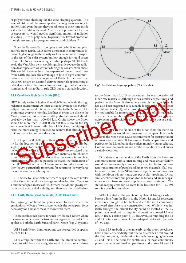
344 Vol 72 No.9/10 September/October 2019 JBIS
of polyethylene shielding for the crew sleeping quarters. This level of risk would be unacceptable for long term workers in an OMPMC even though they spend most of their time inside a shielded orbital settlement. A settlement presumes a lifetime of exposure so would need a significant amount of radiation shielding (~7 m of polythene) to provide the level of protection thought necessary for pregnant women and children [7].
Since the Gateway Earth complex must be built and supplied entirely from Earth, GEO seems a reasonable compromise lo-cation high enough in the gravity well for economical transport to the rest of the solar system but low enough for rapid access from LEO. Nevertheless, a higher orbit, perhaps 60,000 km to avoid the Van Allen belts, would significantly reduce the radia-tion dose especially for workers during the construction phase. This would of course be at the expense of longer travel times from Earth and lose the advantage of line of sight communi-cations with a particular segment of Earth. In the case of an OMPMC reliant on asteroid derived materials approaching at orbital velocities, the power limitations, high radiation envi-ronment and risk to Earth rule GEO out as a suitable location.
3.1.2 Candidate High Earth Orbits (HEO)
HEO is only useful if higher than 60,000 km, outside the high radiation environment. At lunar distance (average 385,000 km) eclipse durations and intervals are similar to the Moon at 12 to 24 minutes every 5.5 months. Satellites in orbits too close to the Moon, however, risk serious orbital perturbations so it should probably be less than ~300,000 km. Orbits above the Moon should be more than ~450,000 km but this is too far for safe and convenient human traffic from LEO. Also, the higher the orbit the more energy is needed to achieve that altitude from LEO so is a factor for consideration.
HEO up to ~300,000 km is therefore an attractive possibil-ity for the location of a settlement or other major facility but slightly less so for the OMPMC because eclipse times are a lit-tle longer and access to lunar resources is more restricted than at L4/L5 (see section 2.4). If, however, materials are obtained from NEAs rather than the Moon then the choice is less clear. Furthermore, it might be possible to match the inclination of the HEO to that of the NEA being mined to reduce even fur-ther the Δv, particularly important for returning the very large masses of raw materials required.
HEO close to Lunar distance where eclipse times are similar to the Moon is therefore a strong candidate location. There are a number of special cases of HEO where the Moon’s gravity im-parts particular orbital stability, and these are discussed below.
3.1.3 Earth/Moon Libration points, L1, L2, L3 and L4/L5
The Lagrange, or libration, points relate to areas where the gravitational effects of two masses equals the centripetal force necessary for a smaller mass to move with them.
There are five such points for each two-bodied system where the mass ratio between the two masses is greater than ~25. This applies to both the Earth-Sun and Earth-Moon (Fig. 2) systems.
All 5 Earth/Moon libration points can be regarded as special cases of HEO.
L1 is always between the Earth and the Moon so commu-nications with both are straightforward. It is also much closer
Fig.1 Earth-Moon Lagrange points. (Not to scale.)
to the Moon than L4/L5 so convenient for transportation of lunar raw materials. Although it has similar eclipse times and periods to the Moon it also suffers monthly Lunar eclipses. It has also been suggested as a suitable location for a fuel depot for cislunar traffic [8], which would make it very busy, proba-bly not suitable for importing large quantities of raw materials. There are also orbital instability issues so station keeping re-quirements and possible traffic congestion rule it out as a suit-able location.
L2 is always on the far side of the Moon from the Earth so communications would be unnecessarily complex. It is much closer to the Moon than L4/L5 so convenient for transportation of lunar raw materials. It has similar Earth eclipse times and periods to the Moon but it also suffers monthly Lunar eclipses. Communication problems and orbital instabilities rule it out as a suitable location.
L3 is always on the far side of the Earth from the Moon so communications with a lunar mining and mass-driver facility would be unnecessarily complex. It is also too far for conven-ient transportation of people and lunar raw materials. If all ma-terials are derived from NEAs, however, poor communications with the Moon will not cause any particular problems. L3 has similar eclipse times and periods to the Moon and lunar eclips-es are not an issue so power supply is almost continuous. The stationkeeping costs for L3 seem to be less than for L1, L2 [9] so it is a possible candidate.
L4/L5 Located at the points of equilateral triangles whose base is a line from the Earth to the Moon, L4 and L5 represent areas once thought to be stable and are the most commonly proposed sites for space construction sites. While it was in-itially thought the orbital facility could be located at the L5 point, later work with computer simulations showed L5 was not, in itself, a stable point [10]. However, surrounding the L4 and L5 points are strange, kidney-shaped orbits with periods of ~90 days.
L4 and L5 are both in the same orbit as the moon so eclipses have a similar periodicity, but due to a satellite’s orbit around the libration point, the duration is much less ranging between 70 and 160 s. The need for continuous, or near continuous, power demands minimal eclipse times and makes L4 and L5
STEPHEN GUNN & RICHARD SOILLEUX
Subscriber copy

JBIS Vol 72 No.9/10 September/October 2019 345
very strong candidates.
3.1.4 Distant Retrograde Orbits (DROs)
Distant Retrograde Orbits (DROs) are a fundamental class of solutions in the Circular Restricted Three Body Problem (CRT-BP). They are a family of stable planar periodic orbits about the smaller primary so for the Earth-Moon system they appear to orbit the moon in a retrograde and relatively periodic motion. However, they are in fact elliptical orbits around the Earth that happen to include the Moon so can be regarded as special cases of HEO (Figure 3). This is a key contributing factor for their exceptional stability compared to similar Prograde Circular Or-bits (PCOs) because they are dominated by Earth’s gravity and much less subject to the uneven gravity field of the Moon. The retrograde motion is best explained by considering that when an orbiting spacecraft is farthest from Earth on the Lunar far side it moves more slowly in its orbit than the Moon and ap-pears to fall behind. The opposite is true when it is closer to Earth and orbits faster than the Moon so appears to overtake it.
DROs represent desirable orbits in cis-lunar space due to the low variation in sensitivity over each revolution. Such a DRO has been proposed as the target location for a boulder captured from an asteroid for the Asteroid Redirect Mission (ARM) [12]. The largest practical DRO mean radius, r0, is desirable in this context to minimize the Δv necessary to achieve a stable DRO for a redirected NEA eg of mass ~500 mt [13]. This fea-ture will be very important for the OMPMC.
The 70,000 km DRO orbit chosen for ARM and shown in Figure 2 has a zero out of plane amplitude eliminating the need for any planar corrections for spacecraft travelling from Earth. Simulations at r0 = 70,000 km indicate a stable DRO in the Moon's geocentric orbit plane remains within 2° throughout
THE OPTIMUM LOCATION FOR AN ORBITAL MATERIALS PROCESSING AND MANUFACTURING COMPLEX utilizing extra-terrestrial materials
Fig.2 Illustration of an Earth–Moon DRO. (Copied from [11])
a subsequent 100-year coast. This degree of planar alignment virtually eliminates corresponding Earth return Δv variations from an orbiting OMPMC. There is, however, a significant dif-ference in transit time depending on whether the OMPMC is nearest or farthest from Earth. It is clearly most economical if journeys are timed to coincide with closest approach with favourable launch windows every 2 weeks. Conversely, incom-ing deliveries of raw materials would best be received when the OMPMC is on the Lunar far side orbiting most slowly and well away from any possibility of collision with crewed spacecraft.
This planar alignment does, however, result in frequent eclipses leading to communication blackouts of ~3.5 hrs du-ration once every period (~14 days), managed easily with relay satellites. Solar eclipses at this distance occur twice yearly and last ~4 hr [13] so also need management. This could perhaps be done for the OMPMC by a holiday with essential services powered during a regular test of the back-up power supply.
These occultations could be minimized with a slightly in-clined DRO orbit, although the stability and Earth access prop-erties would need to be reassessed. An inclined orbit would, however, require planar corrections and their Δv costs during transit to and from the Earth. It is conceivable that this cost could be offset if the degree of inclination could be matched to that of the NEA being exploited and thereby reduce the Δv costs of returning raw materials.
Assessments with solutions satisfying stability criteria for 100 years at r0 = 70,000 km show that an inert asteroid or bulk object whose mass exceeds 200 t should stay in such a stable DRO because its motion does not suffer appreciable acceler-ations from non-gravitational forces [13]. This does not apply for crewed spacecraft such as the OMPMC which are subject to forces from gaseous venting, fluid dumping, arrivals and de-
Subscriber copy

346 Vol 72 No.9/10 September/October 2019 JBIS
partures of spacecraft and raw materials. However, these per-turbations apply wherever the OMPMC is located and require some station keeping and attitude control.
Certain stable DRO orbits are consequently strong candi-dates for the location of the OMPMC especially if the incidence of solar eclipses can be reduced.
3.2 Lunar orbits
NASA has reviewed a range of candidate orbits for its proposed Lunar Orbital Platform-Gateway (LOP-G) [14]. These orbits are characterized in Table 2 (copied from Table 1 in reference [14]) along with estimates of station keeping costs.
3.2.1 Low Lunar Orbits (LLO)
LLOs are circular and of the order of 100 km from the Moon’s surface. They are therefore fairly deep in the Moon’s gravity well so in scenarios with minimum plane change with a 3-5 day transfer from Earth, for example, the ∆v is at a minimum of ~900 m.s-1. Also, at such close proximity to the lunar surface the orbital dynamics are complicated by the presence of Mas-cons (mass concentrations). Furthermore, half of each orbit is in shadow from the Moon and out of line-of sight communi-cations with Earth. These orbits also have similar Earth eclipse times as for the Moon itself. LLO is therefore not considered a suitable location for the OMPMC.
3.2.2 Elliptical Lunar Orbits (ELO)
ELOs tend to be unstable because of perturbance by Earth and Sun gravitational forces especially near apolune. Worryingly, simulations of the orbital dynamics often result in close (and sometimes impacting) approaches at perilune. Such simu-lations have also demonstrated excessive ∆v costs for station keeping, and, while preliminary, the results indicate a total cost of ~300 m.s-1/year [14]. For these reasons, ELOs are not consid-ered suitable locations for the manufacturing complex.
3.2.3 Prograde Circular Orbits (PCO)
PCOs can be highly stable, requiring few to no corrections to be maintained [14] although they tend to be less stable than DROs. They are, however, at high orbital inclination (~75°) so would be expensive in terms of ∆v costs for materials returned from NEAs which rule them out as suitable locations for the OMPMC.
3.2.4 Frozen Lunar Orbits (FLO)
Frozen orbits are similar to PCOs but need not be circular and have orbital parameters that oscillate around fixed values. Fro-zen orbits depend for their stability on unique aspects of the
TABLE 1 (Table 1 in [17]) Characteristics of selected Lunar orbits Orbit Type Orbit Period (Days:hrs) Lunar Amplitude (km) E-M Orientation Station keeping cost
(m.s-1 of ∆V)
LLO ~0:02 100 Any inclination 50–100
PCO 0:11 3,000–5,000 ~75° inclination 0
FLO 0:13 880–8800 40° inclination 0
ELO 0:14 100–10,000 Equatorial ~300
NRO 6-8 2,000–75,000 Roughly polar 10
DRO ~14 70,000 Equatorial 0
gravitational potentials that cancel the effects of shape irregu-larities [14]. Frozen orbits exist for only certain combinations of energy, eccentricity and inclination so finding examples that balance other constraints can be difficult and at this stage they cannot be recommended as suitable locations for the OMPMC. 3.2.5 Near Rectilinear Halo Orbits (NRHOs)
NRHOs are halo orbits with large amplitudes over either the Lu-nar North or South pole with shorter periods that pass closely to the opposite pole. While they appear to look like large ellip-tical orbits, they are CRTBP orbits that remain relatively fixed in the Earth-Moon plane, rotating at the same rate as the Moon around the Earth and the Moon around its own axis. NASA has proposed that the LOP-G should be placed in a highly elliptical NRHO around the Moon to bring the station within 1,500 km of the lunar surface at closest approach and as far as 70,000 km on a six-day orbit. This orbit allows lunar expeditions from the Gateway to reach a polar LLO using 730 m.s-1 of ∆v/day while <10 m.s-1 of ∆v/year is required for stationkeeping. The Gateway could conceivably also support in-situ resource utili-zation (ISRU) development and testing from lunar and asteroid resources [14] and thus become a test-bed for the OMPMC.
A near polar orbit is not, however, suitable for the OMPMC because of the relatively high ∆v costs for materials returned from NEAs.
4 STATION KEEPING ISSUES
All the above candidate orbits have station-keeping require-ments due to perturbations by Earth’s non-spherical gravita-tional field, the gravitational pulls of Sun, Moon and Jupiter as well as solar pressure on the solar arrays. They also need orientation control to keep the solar power arrays facing the sun and radiators deep space. In addition, crewed spacecraft such as the OMPMC are subject to forces from gaseous vent-ing, fluid dumping, arrivals and departures of spacecraft and raw materials.
4.1 Station-keeping in HEO
No examples can be found for a satellite in a very high (300,000 km) HEO and the nearest model for the station-keeping re-quirements is probably NASA’s Geostationary Operational Environmental Satellite, GOES-R [13]. GOES-R has mass ~ 2 t and characteristic length ~1m. A habitat similar to O’Neill’s Island 1 will have mass ~6 x 10⁷ t with characteristic length ~500m (radius), and the demand on the systems will be com-mensurately larger.
Though in GEO / HEO there is no significant problem with atmospheric drag as in LEO:
STEPHEN GUNN & RICHARD SOILLEUX
Subscriber copy

JBIS Vol 72 No.9/10 September/October 2019 347
• the orbit of a satellite is subject to east-west perturbations by Earth’s non-spherical gravitational field to increase the orbital inclination,
• the gravitational pulls of sun, moon and Jupiter will cause minor perturbations,
• solar pressure on the solar arrays may contribute unwant-ed angular momentum.
4.1.1 HEO: Gravitational Perturbations
Station keeping for GOES-R requires a ΔV of ~50 m.s-1 per year, dominated by the contribution of north-south firings of attitude rockets to counter the inclination drift [13]. Since the gravitational acceleration on a body is independent of its mass, similar ΔV challenges should be expected for a large habitat.
The required station-keeping thrust for GOES-R, averaged over a year, is ~3 millinewtons, and a solar-electric propulsion solution is applied. For the habitat the average thrust required to deliver 50 m.s-1 per year is ~ 100 kN.
This could be achieved with liquid-fuel rockets. For exam-ple, the space shuttle’s orbital manoeuvring system (OMS) had a thrust of 27 kN but a continuous, averaged thrust of 100 kN is required. With a total mass of fuel plus propellant of ~20 t the OMS was capable of delivering a total ΔV of 300 m.s-1 to a mass (payload of 65,000lb plus orbiter dry mass) of ~100 t. To deliver a ΔV of 50 m.s-1 per year to a payload of 6 x 10⁷ t would consume an annual fuel-propellant mass of ~ 2.2 x 10⁶ t, a sig-nificant amount.
Alternatively, a perfectly reflective solar sail of area 11,000 km2 could be deployed. This is a large sail, of radius ~60 km, but once installed the thrust it delivered would be essentially free.
4.1.2 HEO: Precessional forces and habitat design
If a rotating habitat is required to keep one pole pointing at the sun to utilize end-cap solar panels, power is required not only for station keeping but also to overcome precessional forc-es to turn it 1° per day as it orbits the sun. For a habitat of the above mass and dimensions this requirement is estimated to be ~300 kN, equivalent to a ΔV of 150 m.s-1, 6 times the amount necessary for station-keeping with 6 times the fuel demand. It appears therefore that a sun pointing rotating habitat is un-affordable but careful design can avoid the problem. For ex-ample, a design with counter-rotating double hulls has no net angular momentum because the hull bearing system resists the considerable precessional forces identified above. The structure as a whole must rotate once a year to remain sun facing but once this motion is established it should continue indefinitely aside from minor attitude adjustments. Alternatively, a habi-tat rotating at right angles to the plane of the ecliptic always maintains the same sunward orientation, will not precess, and avoids the problem entirely.
The impact of precessional forces on habitat design is the same for all orbits and will not be discussed further. The prob-lem does not occur at all of course for non-rotating spacecraft and whether or not it is a factor for an OMPMC will depend on whether pseudogravity is necessary for a particular process and must be allowed for in the design.
4.1.3 HEO: Solar Pressure
For GOES-R, differential solar pressure imposes a net gain/loss
of angular momentum (AM) of ~20 kg m.s-1 per day [15].
The length scale of GEOS-R is ~1m and so the area inter-cepted by the satellite’s solar panels is of the order of square metres. Scaling this up to the dimension of the habitat (radius 500m) implies a gain/loss of angular momentum through this means for the habitat of 3.142 x 5002 x 20 = 1.6 x 10⁷ kg m.s-1 per day. This could be countered by a turning force applied at the radius and acting through the day, of less than a newton making this requirement for a momentum change relatively trivial.
4.2 Station-keeping at L4/L5
If the habitat is at L4/L5 the solar pressure moment should pose similar challenges as at GEO and need not be considered further.
The Lagrangian points L4/L5 are dynamically ‘quasi-stable’ in that a “halo” orbit or a closer-in ‘Lissajous orbit’ around the libration point remains stable for extended periods, even years, without the use of the spacecraft’s propulsion system. A recent (2004) survey and numerical modelling exercise [15] of sta-tion-keeping requirements at all the Earth-Moon Lagrangian locations includes estimates of the amount of station-keeping along with a ΔV cost necessary to keep a spacecraft reasonably close to the theoretical L4/5 point. It shows that constraining an L4/L5 orbit size would cancel much of these natural orbital dynamics [15] and be unmanageable from a ΔV cost perspec-tive. If objects orbiting L4/5 are allowed to wander quite widely, however, fuel costs are much more affordable.
In practice, the orbit becomes perturbed by third-body ac-celerations from terrestrial, solar, lunar and Jovian gravities so some station keeping adjustments are required to prevent a craft from ultimately drifting away. It was estimated [15] that “these [station keeping] costs [in terms of ΔV] can range from centimetres per second per year for the quasi-stable orbits of the L3, L4 / L5 locations to tens, possibly hundreds of meters per second for the unstable L1 and L2 locations.” The L3 loca-tion is quasi-stable in that selection of correct initial velocities can keep the spacecraft in the vicinity for approximately a year without the need for additional control efforts.
Consequently, in the case of an Avalon class habitat at L4/5, station-keeping costs should not exceed ~1 m/s per year which equates to a thrust of ~2,000 N which could be delivered by a solar sail of radius ~9km or an STS OMS-equivalent rocket system at the cost of 44,000 t of fuel per year.
Therefore, provided the orbits around L4/L5 are allowed to evolve, the station-keeping requirements are significantly less than for HEO making these the most attractive options.
In addition, the small but continuous thrust available from using a solar sail opens up new opportunities for powered or-bits. It has been shown [22] that complementing the classical CRTBP with a solar sail creates additional families of orbits. Furthermore, by pitching the sail at an angle with respect to the Earth-Moon plane, solar sail propulsion allows classical orbit families that exist only in the Earth-Moon plane to be extended in the out-of- plane direction. This manoeuvre raises the intriguing possibility of finding orbits that avoid eclipses altogether.
Although the solar sail induced acceleration can have a pos-
THE OPTIMUM LOCATION FOR AN ORBITAL MATERIALS PROCESSING AND MANUFACTURING COMPLEX utilizing extra-terrestrial materials
Subscriber copy

348 Vol 72 No.9/10 September/October 2019 JBIS
itive effect on the stability of some orbit families, especially those at the L2 point, it most often (further) destabilizes the orbit. Active control will therefore be needed to ensure long-term survivability of these orbits.
4.3 Station-keeping for Lunar orbits
Three of the orbits shown in Table 2 meet the stability con-straint; the Frozen orbit, the PCOs and the DROs all exhibit multi-year stability requiring no corrective manoeuvres. The Frozen orbit will vary slightly in eccentricity from 0.6 to 0.7, but the rest of the orbital parameters are fixed. The PCOs and DROs may not be frozen, but exhibit predictable repeatablebehaviour without impacting accessibility.
The remaining four lunar orbits have been studied consider-ing the effects of gravitational forces only to enable assessment of natural orbit instability.
For LLO the total stationkeeping cost with corrections only applied when the orbit altitude was less than 50 km resulting in a ∆V requirement between 50 and 100 m.s-1/year depending in orbit inclination. For the ELO, a few simulations calculated ∆V costs and, while the results are preliminary, the total cost was ~300 m.s-1/year. With a large apolune influenced by Earth and Sun gravitational forces, the trajectory can be perturbed easily to a worryingly close (and often impacting) approach at perilune.
For Earth-Moon L2 halos, the Artemis mission has demon-strated successful stationkeeping for a quasi-halo orbit at the rate of less than 5 m.s-1/year [14]. Further studies on libration point station keeping suggest that libration point orbits in general may require from 5 to 50 m/s depending on the size of the halo.
NRHOs are a subset of L2 halos and are predicted to have higher stability than the larger halos with total cost around 5 m.s-1 per year. Computer simulations have verified these costs with station keeping manoeuvres once per revolution (~7 days) resulting in an annual ΔV requirement of 2.6 m.s-1 [14], very similar to the evolving L4/L5 value.
The quasi-stable L3 location has not yet been used for any spacecraft and unless further study reveals particular advan-tages to this orbit it cannot be recommended for the OMPMC. However, on the basis of minimal station keeping costs FLOs, PCOs and DROs at ΔV 0 m.s-1, L4/L5 at ΔV 1 m.s-1 and NRHOs at ΔV 2.6 m.s-1 all look attractive as locations.
5 FINAL CHOICE OF ORBIT FOR THE FIRST OMPMC
Likely locations based on the above discussion are summarized in Table 2. Most candidate orbits can be discounted on the grounds of safety, crowding or because they are energetically unfavourable and are omitted from the table. This leaves HEO, certain special cases of HEO including DROs and L4/L5 as the main contenders. Indeed, there is little to choose between ~300,000 km HEO, certain DRO’s and L4/L5 with regard to easy access to extra-terrestrial resources, ease of communica-tions, short eclipse times and locations away from most future Earth-Lunar traffic.
Of these possibilities L4/L5 has the shortest eclipse times and has the edge if all raw materials are sourced from the Moon but, in energy terms, recovery of all necessary materials should be much more economical from NEAs, which negates this ad-vantage. A DRO then looks a distinct possibility for the loca-tion of the first OMPMC.
6 CONCLUSIONS
Most candidate orbits for the first OMPMC can be discounted on the grounds of safety, crowding or because they are ener-getically unfavourable. This leaves HEO, certain special cases of HEO including DROs and L4/L5 as the main contenders. It has not proved possible, however, to narrow the choice down to a single orbit, or class of orbits. Indeed, it is unlikely that a final choice will be made until detailed studies are carried out using high-fidelity ephemeris models, such as those being per-formed for the LOP-G project [16]. It is possible that such stud-ies would reveal unexpected advantages and/or disadvantages for some of the proposed orbits or even discover attractive new orbital classes.
Following O’Neill, L5 will be used here and in associated papers and studies to designate the location with the under-standing that it is shorthand for all three libration points and 70,000 km DRO unless they need to be specified for specific purposes.
Acknowledgements
We wish to thank Stephen Baxter for his valuable work on sta-tion keeping and Mark Hempsell for helpful discussions on candidate orbits. Adam Hibberd has also given much helpful advice on the various orbits and helped with checking orbital parameters.
TABLE 2 Pros and cons of likely locations for the OMPMC
Location Advantages Disadvantages
High Earth Orbit (HEO) Good for NEA resources. Good communications. Short eclipse times.
Access to lunar resources slightly less favourable than L4/L5. Some station keeping issues.
Earth/Moon L4/L5 Good access to Lunar and NEA resources. Minimal eclipse times. Minimal station keeping costs.
Quasi-stable location, evolving orbits to minimize station keeping costs.
Distant Retrograde Orbit (DRO) Good access to lunar raw materials. Energetically accessible from HEO and NEA orbit. Stable with minimal station keeping ∆V.
Some power loss and communication issues from eclipses but these could be minimized with inclined orbits.
STEPHEN GUNN & RICHARD SOILLEUX
Subscriber copy
JBIS Vol 72 No.9/10 September/October 2019 349
1. G.K. O’Neill, The High Frontier: Human Colonies in Space, Corgi Books, 1978.
2. R. Johnson and C. Holbrow. “Space Settlements: a Design Study”, NASA SP- 413, NASA Ames Research Center, Moffett Field, CA, 1977.
3. S.D. Gunn and R.J. Soilleux. “A Rationale for Developing and Locating an Orbital Manufacturing Facility Utilizing Extra-terrestrial Materials”. JBIS Vol 72 No. 9 Sept 2019, pps 332-341.
4. A. Globus, S. Covey and D. Faber. “Space Settlement: an easier way”. NSS Space Settlement Journal, July 2017
5. A. Globus and T. Marotta. “The High Frontier: An Easier Way,” P 73, 2018, Pub. CreateSpace Independent Publishing Platform, ISBN-10: 1719231745, ISBN-13: 978-1719231749
6. M. Vidmar, F. Augrandjean, M. Cohen, S. Doublet and A. Millar. “Developing the Technical and Operational Framework for Gateway Earth Space Access Architecture”. JBIS Vol 71 2018 Ps 100–111
7. A. Globus and J. Strout. “Orbital Space Settlement Radiation Shielding”, NSS Space Settlement Journal, April 2017
8. D. Smitherman and G. Woodcock. “Space Transportation Infrastructure Supported by Propellant Depots”. AIAA, June 2011.
9. D. Folta and F. Vaughn. “A Survey of Earth-Moon Libration Orbits: Station-keeping Strategies and Intra-Orbit Transfers”, NASA Goddard
Space Flight Centre, 2004.
10. A.A. Kamel. “Perturbation Theory Based on Lie Transformations and Its Application to the Stability of Motion Near Sun-Perturbed Earth-Moon Triangular Libration Points”, Stanford University, 1970.
11. N. Strangea et al. “Overview of Mission Design for NASA Asteroid Redirect Robotic Mission Concept” IEPC-2013-321. 33rd International Electric Propulsion Conference. The George Washington University, October 6 – 10, 2013 (Figure 7. Copied)
12. “Asteroid Retrieval Feasibility Study”. Prepared for the: Keck Institute for Space Studies, Cal Tech. JPL, Pasadena, CA. 2012
13. D. Chu et al, “GOES-R Stationkeeping and Momentum Management”, 29th Annual AAS Guidance and Control Conference, Breckenridge, CO., 4-8, 2006.
14. R. Whitley and R. Martinez. “Options for Staging Orbits in Cis-Lunar Space”. IEEE Aerospace Conference, March 2016.
15 D.R. Adamo, D.F. Lester, H.A. Thronson and B.W. Barbee. “A class of Selenocentric Retrograde Orbits with innovative applications to human lunar operations”. AIAA, 2018.
16. E.M. Zimovan, K.C. Howell and D.C. Davis. “Near rectilinear halo orbits and their application in cis-lunar space”. IAA-AAS-DyCoSS3-125 2017.
REFERENCES
Received 24 September 2019 Approved 6 December 2019
THE OPTIMUM LOCATION FOR AN ORBITAL MATERIALS PROCESSING AND MANUFACTURING COMPLEX utilizing extra-terrestrial materials
Subscriber copy
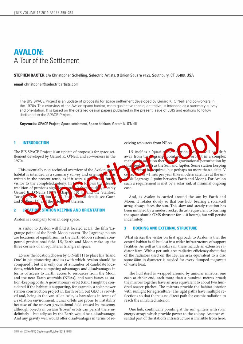
350 Vol 72 No.9/10 September/October 2019 JBIS
AVALON: A Tour of the Settlement
STEPHEN BAXTER, c/o Christopher Schelling, Selectric Artists, 9 Union Square #123, Southbury, CT 06488, USA
email [email protected]
The BIS SPACE Project is an update of proposals for space settlement developed by Gerard K. O’Neill and co-workers in the 1970s. This overview of the Avalon space habitat, more qualitative than quantitative, is intended as a summary survey and orientation. It is based on the detailed design papers published in the present issue of JBIS and editions to follow dedicated to the SPACE Project. Keywords: SPACE Project, Space settlement, Space habitats, Gerard K. O’Neill
JBIS VOLUME 72 2019 PAGES 350–354
1 INTRODUCTION
The BIS SPACE Project is an update of proposals for space set-tlement developed by Gerard K. O’Neill and co-workers in the 1970s.
This essentially non-technical overview of the Avalon space habitat is intended as a summary survey and orientation. It is written in the present tense, as if it were a guide to a future visitor to the completed colony. In this it follows the literary tradition of previous significant space habitat studies, notably Gerard K. O’Neill’s (1978 - chapter 10) [1] and the ‘Stanford Torus’ (1977 - Section 5) [2]. For technical details see Gunn and Soilleux [3] and the references therein.
2 LOCATION, STATION KEEPING AND ORIENTATION
Avalon is a company town in deep space.
A visitor to Avalon will find it located at L5, the fifth ‘La-grange point’ of the Earth-Moon system. The Lagrange points are locations of equilibrium in the Earth-Moon system’s com-pound gravitational field. L5, Earth and Moon make up the three corners of an equilateral triangle in space.
L5 was the location chosen by O’Neill [1] to place his ‘Island One’ in his pioneering studies (with which Avalon should be compared), but it is only one of a number of candidate loca-tions, which have competing advantages and disadvantages in terms of access to Earth, access to resources from the Moon and the near-Earth asteroids (NEAs), and such issues as sta-tion-keeping costs. A geostationary orbit (GEO) might be con-sidered if the habitat is supporting, for example, a solar-power station construction project in Earth orbit, but GEO is crowd-ed and, being in the van Allen belts, is hazardous in terms of a radiation environment. Lunar orbits are prone to instability because of the uneven gravitational field caused by mascons, although objects in certain ‘frozen’ orbits can persist there in-definitely – but eclipses by the Earth would be a disadvantage. And any gravity well would offer disadvantages in terms of re-
ceiving resources from NEAs.
L5 itself is a ‘quasi-stable’ location; Avalon will not drift away from the Lagrange point but will orbit it in a complex manner. In addition there can be gravitational perturbation by other bodies such as the Sun and Jupiter. Some station keeping will therefore be required, but perhaps no more than a delta-V correction of ~1 m/s per year (like modern satellites at the un-stable Lagrange-1 point between Earth and Moon). For Avalon such a requirement is met by a solar sail, at minimal ongoing cost.
And, as Avalon is carried around the sun by Earth and Moon, it rotates slowly so that one hub, bearing a solar-cell array, always faces the sun. This slow and steady rotation has been initiated by a modest rocket thrust (equivalent to burning the space shuttle OMS thruster for ~10 hours), but will persist indefinitely.
3 DOCKING AND EXTERNAL STRUCTURE
What strikes the visitor on first approach to Avalon is that the central habitat is all but lost in a wider infrastructure of support facilities. As well as the solar sail, these include an extensive ra-diator farm. With a per-unit-area radiative efficiency about that of the radiators used on the ISS, an area equivalent to a disc some 80m in diameter is needed for every dumped megawatt of waste heat.
The hull itself is wrapped around by annular mirrors, one each at either end, each more than a hundred metres broad; the mirrors together have an area equivalent to about two hun-dred soccer pitches. The mirrors provide the habitat interior with sunlight for agriculture. The light paths have multiple re-flections so that there is no direct path for cosmic radiation to reach the inhabited interior.
One hub, continually pointing at the sun, glitters with solar energy arrays which provide power to the colony. Another es-sential part of the station’s infrastructure is invisible from here:
Subscriber copy
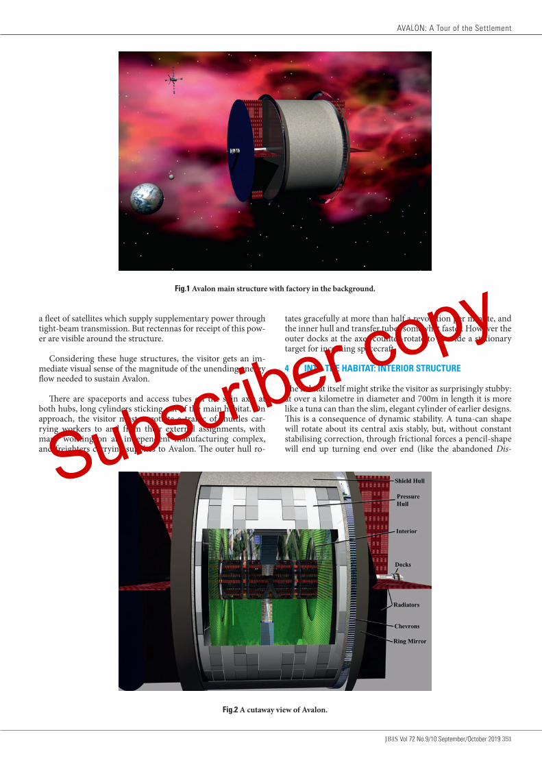
JBIS Vol 72 No.9/10 September/October 2019 351
a fleet of satellites which supply supplementary power through tight-beam transmission. But rectennas for receipt of this pow-er are visible around the structure.
Considering these huge structures, the visitor gets an im-mediate visual sense of the magnitude of the unending energy flow needed to sustain Avalon.
There are spaceports and access tubes on the spin axis at both hubs, long cylinders sticking out of the main habitat. On approach, the visitor must negotiate a traffic of shuttles car-rying workers to and from their external assignments, with many working on an independent manufacturing complex, and freighters carrying supplies to Avalon. The outer hull ro-
Fig.1 Avalon main structure with factory in the background.
tates gracefully at more than half a revolution per minute, and the inner hull and transfer tubes somewhat faster. However the outer docks at the axes counter-rotate to provide a stationary target for incoming spacecraft.
4 INTO THE HABITAT: INTERIOR STRUCTURE
The habitat itself might strike the visitor as surprisingly stubby: at over a kilometre in diameter and 700m in length it is more like a tuna can than the slim, elegant cylinder of earlier designs. This is a consequence of dynamic stability. A tuna-can shape will rotate about its central axis stably, but, without constant stabilising correction, through frictional forces a pencil-shape will end up turning end over end (like the abandoned Dis-
Fig.2 A cutaway view of Avalon.
AVALON: A Tour of the Settlement
Subscriber copy

352 Vol 72 No.9/10 September/October 2019 JBIS
covery in the movie 2010: The Year We Made Contact, dir. P. Hyams, 1984).
Entering the habitat through the axial hub gives a glimpse of its overall structure. As mentioned above the station actual-ly has two cylindrical hulls, one turning inside the other, after the manner of a Tibetan prayer wheel. The total mass of the habitat is 60 million tonnes – about 150,000 times the mass of the ISS. Of this total mass the outer ‘radiation shell’, is mostly anhydrous glass (AG) supported by a framework and cladding of steel, amounts to 70%. Such shielding, to protect the inhab-itants against radiation, is essential for any habitat beyond the Earth’s magnetosphere.
The interior ‘pressure hull’, mostly steel, rotates more than once a minute, to provide a spin gravity equivalent to Earth’s on its inner surface. The radiation shell counter-rotates at half this rate. This design reduces the structural loading imposed by the great mass of the shielding material; the spin gravity for the radiation shell is only about 20% G. The two hulls are dy-namically coupled by a system of circumferential maglev rails, which maintain the hulls’ separation without physical contact or friction.
This arrangement constitutes a key advantage over the O’Neill Island One design. O’Neill had shielding over only part of the structure - not over the agricultural areas – and, firmly bonded to a single hull, that shielding exerted excessive structural stress. (There is some comparison with the ‘Stanford Torus’ study [2] in which a wheel-shaped habitat consisted of a lightweight inner compartment rotating within a stationary shield of Moon rock shielding.)
The counter-rotation of the hulls is essential to ensure that the station as a whole has zero angular momentum, and so has no gyroscopic resistance to angular motion. Avalon needs no significant external torque to maintain its sun-facing orien-tation. Internally, however, the counter-rotating hulls impose torques on each other. This is comparable to O’Neill’s Island Three, which had two counter-rotating cylinders held in par-
Fig.3 A view of the interior from the ground looking up.
allel in a torque-bearing framework of external struts. In the case of Avalon, the maglev system mediates the precession torque forces.
5 AN ECOSPHERE IN SPACE
Inside the habitat, the visitor passes through a final airlock into a cylinder full of light and air. Gravity is zero at the axis, but even here air pressure is lower by only a few per cent compared to the hull level, and the air temperature remains essentially the same throughout the habitat. And the air is fresh, with the scent of growing things. Compared to the heavily recycled canned air of a transfer ferry, it might be like entering a tre-mendous greenhouse.
The interior of Avalon, bathed in sunlight, with a farmed landscape curving up over the visitor’s head, is a spectacu-lar, colourful sight. An axial duct for access and maintenance draws the eye to the far hub. Around the centre of the far hub is a sunlight window, and around that the glass wall of an en-closed greenhouse. Halfway along the axis, a Y-shaped struc-ture of access shafts links the main axis duct to the inner hull: a striking architectural feature.
Internally the pressure-hull hubs are actually concave, their centres protruding some 60m into the main volume. This is to provide shielded space in vacuum for the inner docks, and also for dynamic reasons; the more mass is brought towards the central plane of the cylindrical habitat the more the rotation-al stability is improved. These concave caps are fronted by flat glass sheets: the result is a pair of annular greenhouses, built around the axis facilities and used for hydroponic farming.
The visitor takes an elevator down through the access shafts to the hull level. Walkways and ladders are visible on the glass front of the greenhouse, for access, emergency exit and recre-ation.
People live and work on several levels. Beneath the ‘main floor’ are three lower decks, used for air conditioning plant and
STEPHEN BAXTER
Subscriber copy

JBIS Vol 72 No.9/10 September/October 2019 353
other equipment, transport, and storage. Above the main floor there can be as many as three raised levels, after the manner of terracing, all adding to the available surface area. In total, the main floor area is around 2 km2 – about 500 acres. Of this about 170 acres is dedicated to agriculture.
Avalon aims for the (inevitably imperfect) closure of recy-cling loops of water, air and mass – although raw materials must be imported to replace products such as wood and cotton removed from the ecosystem for use by the colonists. It is how-ever open to flows of energy.
Regarding input of energy, sunlight, collected by the mir-rors, is used for photosynthesis (supplemented in places by heat-efficient LED lamps). The hub solar cell farm supplies the electrical power needed to maintain the environment.
Regarding output of energy, waste heat, equivalent to the energy inflow, must be dumped to space through the radiator farm, and this requires air conditioning. The air contained by Avalon masses about four hundred thousand tonnes, equiva-lent to more than one hundred times that contained by NASA’s Vertical Assembly Building.
The whole of the habitat’s air is processed at a rate of 0.15 air changes per hour (ACH). This may seem low; it compares to one an hour for the VAB, and is about 100 times lower than the equivalent value for the Earthbound experimental habitat Biosphere 2. However, the very large size of Avalon, even com-pared to the VAB, has driven a compromise design.
Small occupied enclosed spaces need many more ACH to avoid the accumulation of warm, moist, stagnant air with haz-ardous concentrations of CO2. The situation inside Avalon is analogous to that on Earth, where small occupied buildings must be continuously ventilated by fresh air from ‘outside’. On Earth, natural processes keep the external atmosphere in bal-ance. On Avalon, artificial processes must maintain the quality of this ‘external’ atmosphere, ensuring that temperature and humidity remain within comfortable limits and, most impor-tantly, the CO2 concentration does not reach dangerous levels. Thus the habitat’s overall ACH per se is not the most significant design parameter.
The air is extracted through ducts at the axis and in the floors, and cooled by being forced through heat exchangers at the hubs, from which heat is transferred by closed-loop systems to the external radiators. Water evaporated from the village ar-eas and the farms is condensed by this system; the condensate provides potable water for human and agricultural use.
Meanwhile the air is revitalised by the cycling of carbon dioxide to oxygen by the habitat’s growing plants, which also purify it of toxins. Solid waste from humans and animals is processed using marsh plant recycling and composting.
Natural systems are used as far as possible but there are back-up mechanical systems to ensure balance in this small, poorly buffered closed ecosystem, such as mechanical com-posters, SCWO reactors for the carbon cycle, and Haber-Bosch ammonia synthesis installations to support the nitrogen cycle.
There is continuous daylight in Avalon. Residential areas pro-vide shade and darkness for human comfort, and plants are se-lected for long-daylight tolerance, or are artificially shaded. The temperature is maintained at a comfortable sub-tropical 25 Cen-
tigrade, with low humidity. It is like an endless summer’s day.
6 BUILDING AND MAINTAINING THE SETTLEMENT
The construction of Avalon was a heroic ten-year effort.
Much of the fixed mass of the habitat, some sixty million tonnes, was extracted by mining from carbonaceous near-Earth asteroids, which also provided many volatiles, including nitrogen, the bulk of the habitat’s atmosphere. The construc-tion proceeded in stages, with the hulls being completed and fitted out before spin-up. Extensive use of matter printers en-sured a robust structure. Spin-up was achieved using the mag-lev system, with the counter-rotating hulls pushing against each other.
No system is entirely closed. A leakage loss of 1% per annum of the air (which compares to 10% pa for Biosphere 2) necessi-tates the ongoing delivery of 4000t per year for replenishment.
The system’s projected lifetime is 1000 years. With this in mind much effort has been made in designing in resilience, from a detailed fire analysis and multiple redundancy to a strat-egy of using systems easy to repair in situ rather than requiring replacement.
Clearly any collision of the hulls would constitute a cata-strophic failure. The maglev system would be resilient to the perturbation caused by a docking-speed collision with a craft of the mass of the space shuttle, or by a collapse of inner hull structures spanning tens of square metres. And the system is failsafe in case of power loss, with magnetic friction gradually bringing the hulls to rest. Indeed the bleed-off of kinetic ener-gy from the hulls can be used as a short-term backup power source.
The next main danger is a general loss of power. Without cooling, the inflow of heat from sunlight would quickly render the hull uninhabitable, so reflective louvres would cover the windows, working on a ‘dead man’s switch’ basis. In the longer term, however, with photosynthesis stopped, this would lead to a spoiling of the air, and ultimately food shortage. Emergency systems of independent-power CO2 scrubbers and stored dried food are provided to sustain life until an orderly evacuation can be completed.
7 LIFE IN THE SETTLEMENT
Ten thousand people live and work in Avalon, at a significant population density – comparable to dense urban centres such as Hong Kong.
People live in ‘villages’ amid the farm land. There are fish ponds and fruit trees, and some animals, living mainly on waste products: sheep, goats, chicken, and pigs. Most food and atmospheric recycling however is provided by the hub hydro-ponic farms.
Not all the citizens are productive in terms of the habitat’s economic function. There are children here. Effort is required of the inhabitants to maintain the settlement’s systems, as well as the human infrastructure. For example there are schools and a hospital - the latter supported by ‘ambulance pods’ capable of bringing in casualties from beyond the hull, even from inde-pendent manufacturing complexes and the like. Teachers, doc-tors, nurses will be required to run such facilities.
AVALON: A Tour of the Settlement
Subscriber copy

354 Vol 72 No.9/10 September/October 2019 JBIS
Roughly one-third of the available adult work-days are used on economically productive (mostly external) projects, one-third are used on agriculture, and one-third on systems main-tenance and social support.
This is essentially a company town; the population is mul-tinational. However there is an elected community council, and a UN-appointed marshal oversees the implementation of common law and company rules with proper adherence to human rights.
There are spaces for theatres and movies. Three-kilo-metre running tracks follow the habitat’s circumference, and
low-gravity sports and dance exercises in the regions around the axis are popular. Any visitor soon discerns that the purpose of Avalon is to provide not just a workers’ dormitory, but a con-genial environment in which to live, work, and raise a family – all in deep space.
ACKNOWLEDGEMENTS
The author is grateful to Richard Soilleux and Steve Gunn for detailed feedback on drafts of this paper, to Steve Gunn for the fine illustrations, and to an anonymous reviewer for helpful re-marks.
1. G.K. O’Neill, The High Frontier, William Morrow, 1976. Page numbers from the 1978 Corgi version of the second edition.
2. Johnson, Richard D. and Holbrow, Charles, (editors), “Space Settlements: A Design Study”, NASA SP-413, 1977.
3. S.D.Gunn and R.J.Soilleux, “The Avalon Orbital Settlement”, JBIS, Vol 72 No.9 Sept 2019, pps 302-331.
REFERENCES
Received 20 July 2019 Approved 7 August 2019
STEPHEN BAXTER
Subscriber copy

JBIS Vol 72 No.9/10 September/October 2019 355
JBIS VOLUME 72 2019 PAGES 355–359
AVALON: The Governance of a Company Town in Space
STEPHEN BAXTER1 & ADAM D.A. MANNING LLB, LLM2 1c/o Christopher Schelling, Selectric Artists, 9 Union Square #123, Southbury, CT 06488, USA; 21 Nettlestone, Netley Abbey, Southampton, Hampshire, SO31 5GF, UK
email [email protected] / [email protected]
Avalon, a settlement in space, is intended to be embedded in a system of space law that will allow its inhabitants and controlling entities legally to acquire resources and to trade, and which will enshrine their rights and responsibilities. Such a system is outlined here, based on principles of extant space law, considerations of fundamental human rights, and applicable terrestrial precedents. Keywords: SPACE Project, Avalon, Space habitats, Settlements in space, Space law, Outer Space Treaty, Moon Agreement, Extraterrestrial liberty
1 INTRODUCTION
The Avalon habitat design is an updating of the O’Neill Island One design of the 1970s [1]. Avalon will be a settlement in space hosting several thousand people, including families with chil-dren, embedded in a system of law and governance that will in-clude nations and other entities on (at least) Earth and Moon, as well as other space colonies. Therefore Avalon requires a legal framework that will allow it to acquire resources, such as from the Moon for the construction of the habitat, and including an internal constitutional settlement encoding the rights and re-sponsibilities of its citizens and of the national, corporate or other entities which own or govern Avalon.
But what might that legal framework look like? Extant space law offers guidance on principles, but is not as fully developed either legally or pragmatically as, for example, the case of the law of the sea, a comparable example of the exploitation of a resource held in common by mankind.
In this area, in fact, founding father O’Neill himself was si-lent. For O’Neill, once the great settlements for which he is best known were established, O’Neill imagined them being used as a base for ‘homesteading’ the asteroids [1] (p233), much more economically than if such projects had to be launched from Earth. Against this theoretical background, O’Neill had little to say about the societies within the colonies themselves (P235):
‘I have said nothing about the governance of space communities . . . In my opinion there can be no “revealed truth” about social organisation; there can only be, in any healthy situation, the options of diversity and experimen-tation . . .’ In fact O’Neill saw his gigantic space colonies only as a necessary, short-term evil: indeed, places from which to escape.
Another well-known study with which O’Neill is associated, known generally as the ‘Stanford Torus’ [2], a product of a 1975 workshop involving NASA Ames and Stanford University, did have useful if brief comments to make on the ‘social organisa-
tion and governance’ of the colony (p52ff):‘It seems most likely that government for the initial col-
ony would be based on types of management familiar in government and industry today. There would be elements of representative democracy, but the organization would surely be bureaucratic, especially as long as there is need for close dependency on Earth.’
In general, though, most space habitat studies are focussed strongly on the engineering of the structure as opposed to the sociology and politics of the population.
There are however principles of extant space law and precur-sor Earth-based settlement examples from which to draw rea-sonable suggestions for the legal settlement and social structure of a large, legally operated space community of the future.
2 EXTERNAL RELATIONS: SETTLEMENTS IN SPACE AND SPACE LAW
It is our intention that Avalon should have a basis for its assem-bly and operation that is legal under space law and international law. It is not our intention in this exercise to challenge current space law, or any extension of it, or to operate outside it.
A review of the current status of the law of extraterrestrial resources will be published in this journal [3]. As discussed be-low, space law is not as yet developed enough to allow such a project to proceed with certainty – and the limits of that law are currently being tested by a number of initiatives, for example proposed private asteroid mining projects. Here we assume that in the Avalon future space law will have been developed to a point of maturity comparable to that of the current status of the law of the sea, which is enabling for example the legal extraction of resources from the sea bed, and we make extrapolations from current space law as necessary for the discussion.
The foundations of current space law are the Outer Space Treaty (OST), formally the Treaty on Principles Governing the
Subscriber copy

356 Vol 72 No.9/10 September/October 2019 JBIS
Activities of States in the Exploration and Use of Outer Space, in-cluding the Moon and Other Celestial Bodies, finalised in 1967, and the Moon Agreement, formally the Agreement Governing the Activities of States on the Moon and Other Celestial Bodies, finalised in 1979 [4,5].
As of July 2017, 107 countries are parties to the five-dec-ades-old OST, while another 23 have signed the treaty but have not completed ratification. The Moon Agreement has been challenged since its introduction, but as of November 2016, 17 states are parties to the Agreement, seven of which ratified the Agreement and the rest acceded. This is sufficient for the Agree-ment to have the force of UN law. Today the Moon Agreement, together with its parent the OST, is commonly consulted as the best guide to the future development of space law.
These treaties are however undeveloped as practical instru-ments of law (see below). But they overlap in their discussion of sovereignty and property rights concerning space resources, and are thus highly relevant to a discussion of the legal status of settlements in space.
The OST was a product of the Cold War, in particular a re-action to fears of the militarisation of space, while the Moon Agreement (which actually applies to all bodies in the solar sys-tem save Earth) was prompted by an anticipation that the US-USSR Moon race might lead to territorial appropriation in outer space. But the treaties’ reach is much further than the concerns that originated them.
In particular, the Moon Agreement is explicitly based on the philosophical principles of the concept of the ‘Common Herit-age of Mankind’ (CHM) [6], first developed in the context of the law of the sea. (The OST refers to a broader concept of a ‘prov-ince of mankind’, that is a communal ownership.) According to CHM principles, outer space and its resources, like the resourc-es of the oceans beyond national waters, should be regarded as a ‘commons’, a resource to be used for the benefit of all mankind.
Relevant key principles include:• There can be no permanent appropriation of the territory
of celestial bodies. No claims of sovereignty by any nation are allowed, and therefore there will be no ownership of territory by entities like corporations or individuals (be-cause any such ownership would have to be granted by a sovereign nation). Prior claims of ownership of resources, including subsurface, are also forbidden.
• Resource extraction is permitted, but a common man-agement structure is needed to ensure that any such ex-traction is performed ethically (for instance with regard to environmental protection), and that the benefits from such activities should be shared equitably for the benefit of all mankind.
Thus Article II of the OST states: Outer space, including the Moon and other celestial bodies, is not subject to national appro-priation by claim of sovereignty, by means of use or occupation, or by any other means.
And Article 11 paragraph 5 of the Moon Agreement states: States Parties to this Agreement hereby undertake to establish an international regime, including appropriate procedures, to govern the exploitation of the natural resources of the Moon as such ex-ploitation is about to become feasible . . .
No such ‘international regime’ to govern the exploitation
of space resources yet exists, of course. However there is a key precedent arising from the development of the law of the sea [6].
Since the UN’s development of the relevant governing treaties in the 1960s, the use of sea resources has ‘become feasible’ tech-nologically more rapidly than space exploitation. But even after the law of the sea treaty was ratified, there was much political wrangling in the development of practical arrangements. Less developed nations argued for fair sharing of common resources in the spirit of the CHM. However industrialised nations, who were technologically able actually to exploit the oceans’ resourc-es through such activities as seabed mining, did not want to see their investments and profits dispersed.
In practice, from 1994 the International Seabed Authority (ISA) began to licence exploitation, and to impose levies on profits as a gesture towards equitable sharing. This arrangement has emerged as a politically pragmatic solution for the develop-ment of this particular commons, paying respect to the princi-ples of the CHM.
By the time Avalon is built, we anticipate an analogous de-velopment of a full treaty framework and of an ‘international regime’ governing the use of space resources, to guide the con-struction of the habitat and its operations, perhaps under an ‘In-ternational Space Authority’. Speaking informally, we anticipate ‘common sense’ solutions to various principles to have been hammered out by negotiation and precedent.
In summary governing principles may be:• Avalon will not be the sovereign territory of any nation. • Ownership: Following the precedent of the ISS Interna-
tional Government Agreement (see section 3 below), it seems likely that if part of the fabric of Avalon has been brought up from Earth, then that part is owned by who-ever owned it at the moment of launch, unless it has been transferred subsequently (in which case it is owned by whoever it has been transferred to). On the other hand, following the precedent of the Outer Space Treaty, that part of Avalon made from extraterrestrial resources, such as lunar regolith for the radiation shield, cannot be owned by anyone. With a mixed construction, it seems likely that, as matters stand at present, no one could ‘own’ Avalon at all. Nor could, for example, space within it be rented out to other parties. We anticipate a pragmatic basis for this kind of project and transaction to be recognised in law by the time Avalon is built.
• Avalon’s inhabitants will remain citizens of nations on Earth and will by default be governed by their home na-tions’ laws.
• If the inhabitants of Avalon are employees of a company then their contracts of employment will probably contain clauses specifying which nation’s laws govern the terms and provisions of the contract – probably whichever coun-try that the employer company is registered in. (But see below for a further discussion of Avalon’s internal poli-tics).
• The buying and selling of materials and produce, such as buying lunar resources to build and maintain the habitat, and the sale of any manufactured products and the servic-es of Avalon’s inhabitants, will be regulated by an interna-tional legal regime, perhaps under an ‘International Space Authority’ analogous to the case of the law of the sea, with levies paid as a gesture to CHM principles of equitable sharing.
• The international legal regime will protect the builders of
STEPHEN BAXTER & ADAM MANNING
Subscriber copy

JBIS Vol 72 No.9/10 September/October 2019 357
Avalon from invasion, confiscation, theft and other ap-propriation by outside parties. This provision is necessary because if the resources of space cannot be owned by any-body, there is no protection under customary law against appropriation of what has been built or made: what you do not own cannot be stolen from you.
3 INTERNAL RELATIONS: A COMPANY TOWN IN SPACE
Avalon is to be built to support the industrialisation of space by providing a safe, comfortable, living environment for thousands of workers and their families. How should such a society govern itself?
Major mineral extraction projects in remote areas on Earth may provide examples of how orbital industrial complexes like Avalon might develop socially. Historically such projects have inspired the development of ‘company towns’, which are planned, built and largely owned by a single company, which becomes the main employer in the town; most inhabitants are company employees or their dependants.
Many such towns were established in the US before the Civil War, in Pennsylvania’s mining industry for example [7]. In Rus-sia and later the Soviet Union, company towns were established in remote areas of the Arctic [8] and at such locations as Pripyat (1970), whose workers served the Chernobyl nuclear plant. The establishment of company towns sometimes had an ideological motivation, however, such as the British planned communities of Port Sunlight (1888) and Bourneville (1895) [9], whose cre-ators acted through benevolence, seeking to improve workers’ living conditions, or sometimes ‘paternalism’, in seeking to im-prove the workers’ moral character.
At their peak there were 2500 company towns in the US, em-ploying 3% of the population. Some company towns went on to grow into ‘regular’ communities, while others declined as the employment opportunities withered for instance through ex-haustion of a mine. In the longer term a rise of affluence and im-proved transport links for workers removed the need for most company towns, though some exist today.
Problems encountered often arose from a lack of a democrat-ic voice for the workers. This issue led to the notorious Pullman Strike in Pennsylvania, 1894 [7], after which, in the US, a new standard of expertise of planning and operation grew around the planning of company towns. Elsewhere there could be cul-tural clashes, for example over national differences where im-migrant workers were used, or over religion if the local worship centres were centrally imposed - or over the disguised social engineering of ‘paternalism’ [9].
But in Russia particularly, the isolation and central con-trol of such communities led to outcomes which offer a dire warning to planners of communities like Avalon. [8]. After the opening of the Trans-Siberian Railway in 1891, in the twentieth century, under the Soviets, a purposeful move into the Arctic was made to open up its economic wealth. This regime was of-ten brutal. The working towns, housing a population trapped in the Arctic climate, were often clusters of primitive shacks and vermin-infested dormitories, and there was an endemic shortage of food and other essentials because of unreliable sup-ply lines and corruption.
The population of space islands like Avalon will be even more dependent on the facilities and supplies of their ‘compa-
ny towns in space’ than were the hapless Soviet citizens of the Arctic, and similar threats to life and liberty apply. Cockell [10] identifies the challenges to liberty in extraterrestrial environ-ments as arising from perpetual confinement and a dependence for survival on central communal technological systems: factors which encourage tyrannous regimes, and make rebellion diffi-cult or impossible.
For example, since humans will expire in seconds if deprived of oxygen, the control of the supply of air in particular is central to the question of rights and power. (Consider the movie Total Recall (1990, dir. P. Verhoeven), in which the administrator of a Mars colony has no hesitation in cutting the air supply to a rebellious district.)
For this reason a clear statement of the colonists’ rights will be necessary from the beginning. A key legal way to enshrine such rights could be to link it to the United Nations' Universal Declaration of Human Rights, specifically Article 3, the right to life, liberty and security of the person [11]. In practice the assurance of such rights could mandate some aspects of the col-ony’s design: for example, perhaps nobody should ever be more than a few seconds from an airtight shelter. On the other hand, because of the fragility of the environment, the citizens will have to accept certain responsibilities. A requirement not to damage the habitat’s essential facilities is obvious, but in addition there may be a responsibility to aid in the response to an emergency, for example, to shelter strangers in one’s airtight dwelling until a decompression crisis has passed.
Concerning applicable law and policing, as noted in the previous section, while Avalon could not be the sovereign ter-ritory of any nation, its inhabitants will remain citizens of their originating nations, and thus subject to those nations’ laws. One precedent for how this might work in practice is McMur-do Station in Antarctica [12], a town that must support several hundred inhabitants enduring total isolation during the ‘win-ter-over’ months. Under the auspices of the US’s National Sci-ence Foundation, McMurdo is essentially run bureaucratical-ly, but since 1989 the United States Marshals Service has been the official law enforcement agency, in the form of a deputy in situ answerable to the District of Hawaii. (And, of course, Sean Connery played a US marshal sent to enforce the law in a mining-colony company town on Io, in the movie Outland (1981).)
A more relevant precedent is the code under which the In-ternational Space Station (ISS) currently operates [13]. The ‘Partner States’ who built the ISS concluded an ‘Intergovern-mental Agreement’ (IGA) (1998) which stipulated that relevant UN space conventions applied, including the 1967 Outer Space Treaty and the 1968 Rescue and Return of Astronauts Agree-ment (but not the Moon Agreement). The IGA was designed as a platform for cooperation over such matters as customs and immigration and the exchange of data and goods. Governed by the IGA, Memoranda of Understanding between NASA and the other participating agencies were drawn up, leading to the In-ternational Space Station Code of Conduct [14]. The Partner States (mediated by ESA in the case of the Europeans) translated back the provisions of the code into their own legal systems, so that in effect every crew member on the ISS is governed by the same set of statutes, with a common understanding between the Partners.
The IGA provided explicitly (Article 5.2) that ‘each Partner shall retain jurisdiction and control over the elements it regis-
AVALON: The Governance of a Company Town in Space
Subscriber copy
358 Vol 72 No.9/10 September/October 2019 JBIS
ters … and over personnel in or on the Space Station who are its nationals’. The IGA envisaged, for example, the prosecution of an astronaut following misconduct on orbit; the basis for ex-ercising jurisdiction and making the prosecution would be the nationality of the perpetrator (as opposed to the location of the alleged crime, that is in which nationally owned Station ele-ment). A 2013 report to the United Nations Committee on the Peaceful Uses of Outer Space Legal Subcommittee [13] noted that after 15 years these arrangements had operated smoothly without the need for amendment.
The ISS IGA and associated instruments were the pragmat-ic outcome of an exercise in ‘multicultural’ negotiation over legal and procedural matters in the context of a space station. While Avalon is likely to be dominated by corporate entities rather than states, and its crew will be vastly larger and more diverse than the crew of the ISS, this precedent shows that in practice good will and pragmatism can yield workable solu-tions in terms of legal frameworks – just as the example of the ISA showed that CHM-based treaty principles can be devel-oped into working relationships.
Meanwhile the lessons of more successful company towns on Earth suggest the importance of democracy and accountabili-ty, a tolerance of cultural and individual diversity, and as much control over daily life afforded to individuals as possible within the necessary constraints of the environment.
4 DISCUSSION AND CONCLUSIONS
As a settlement in space, Avalon will be established under a re-gime of space law more mature than that of the present day. We anticipate a development of the principles of the Outer Space Treaty and the Moon Agreement, with an exclusion of appropri-ation through sovereignty claims, and the commercial operation of the colony in accordance with the principles of the common heritage of mankind, as enshrined in both the extant treaties.
The first colonists of Avalon, over and above the rights and responsibilities pertaining to any citizen of a modern technical society, have the right to a safe and civilised living environment, and must accept their own responsibilities in maintaining that environment in a fragile habitat. Perhaps a preliminary consti-tution should be drawn up, outlining the rights and responsi-bilities of the inhabitants, and of the companies and authorities controlling Avalon, before the its formal occupation.
For example, the inhabitants could elect a town council un-der a Mayor, or an equivalent under an appropriate national law. The Mayor in turn could chair an executive governing council with representatives of police bodies (such as an appointed US Marshal, as in the McMurdo case), representatives of the corpo-rate or other bodies involved in the funding of the colony and its trade, and representatives of the engineering and other in-frastructure departments that maintain the fabric of the colony. The Mayor’s chairing, and perhaps a delegate of a UN body such as an ‘International Space Authority’, could serve to protect the inhabitants’ human rights.
What of the further future, however?
The Stanford Torus study [2] is unusual among space habitat studies in offering some speculations in this regard (p52ff):
‘But whatever the [governance] forms initially, they must evolve as the colonists develop a sense of community, and it
is easy to imagine at least two stages of this evolution. First there is the start of colonization by some Earthbased cor-porate or governmental organization. Later, as continued development leads to more and more settlement, the colo-nists form associations and create governance bodies which reflect rising degrees of community identity, integration and separation of decision-making powers from organizations on Earth. These changes evolve first within a single habitat and then cooperative and governmental relations develop when neighbouring habitats and a larger community grow. The rate at which this evolution occurs is uncertain.’
However in detail the consequences of these ‘rising degrees of separation’ from Earth are likely to be complicated.
In fiction it has almost become a commonplace for mature space colonies to seek to break away from the Earth. Perhaps the classic example is Heinlein’s The Moon is a Harsh Mistress [15], a conscious rerun of the American Revolution set in the context of a brutal penal colony on the Moon.
But the legal remedies available to space rebels will be un-precedented. In Steele’s Clarke County, Space [16] the eight thousand disgruntled inhabitants of Clarke County, a working settlement in an eccentric Earth orbit, seek their independence: ‘It doesn’t matter who paid for Clarke County. Legally, it’s a ter-ritory of the United States. Therefore, we can secede from the Union . . . And we shall’ (chapter 3). This presumably builds on the precedents of the southern states that seceded from the Union in the nineteenth century. But the logic is flawed. Under the OST the settlement cannot be a sovereign territory of the United States in the first place, and so Clarke County can rebel, but it cannot secede.
And what of the common heritage of mankind?
The vision of the colonisation of space presented here, en-couraged by the principles embedded in current space law, is based on non-sovereignty, non-private acquisition, and an eq-uitable sharing of the proceeds for the benefit of all mankind. In this regard it is quite different from the American frontier experience – an example often cited (including by O’Neill [1]) as a precedent for space operations – which was based on the sovereignty of the US over the frontier lands which enabled the nation to endorse land claims, and on the development of a new capitalist society.
There have certainly been plenty of ghastly visions in fiction of settlements in space as engines of inequality. The movie Elysi-um (N. Blomkamp, 2013) is a moral parable on these lines. The eponymous Elysium, a wheeled habitat based on the Stanford Torus [2], is a vast settlement, home to the wealthy, orbiting an impoverished and exploited Earth; Elysium is visible in the sky, an ever-present symbol of entrenched inequality.
But perhaps it need not be so [3]. Perhaps the common heritage principle already embedded in current space law pro-vides a philosophical basis for how we, as a society, can move forward without repeating the worst excesses of the historical catastrophes of over-exploitation and inequitable distribution of resources. And certainly the precedent of the law of the sea shows that it is possible to operate a resource-extraction regime without sovereignty and with at least a nod to the more equita-ble principles of the CHM.
One vision of a rebel settlement attempting to found itself on
STEPHEN BAXTER & ADAM MANNING
Subscriber copy
JBIS Vol 72 No.9/10 September/October 2019 359
such principles is Robinson’s ‘Mars’ trilogy [17] [18] [19] (1993-6). Robinson’s Martian colonists rebel, not just against a govern-ment, but against the system of capitalist democracy itself: ‘All economic enterprises are to be small cooperatives, owned by the workers and no one else’ ([18] p144). And the new constitution contains a pledge to use the society’s overall wealth to guarantee equal access to ‘housing, health care, food, education’ (p145). The great experiment evidently works, as Robinson assures us in the very last page of the trilogy: ‘Nowhere on [Mars] were peo-ple killing each other, nowhere were they desperate for shelter or
food, nowhere were they scared for their kids’ (p761).
As for the future of Avalon in the real world, we can only speculate.
Acknowledgements
The authors are grateful to Steve Gunn, Richard Soilleux, Jerry Stone and other members of the SPACE project team for discus-sions, suggestions and input to this study.
1. G.K. O’Neill, The High Frontier, New York, 1976. Page numbers from the 1978 Corgi version, second edition.
2. R.D. Johnson and C. Holbrow (editors), “Space Settlements: A Design Study”, NASA SP-413, 1977.
3. To be published. A Manning, “The law of extraterrestrial Resources”. (Part of the SPACE Project)..
4. http://www.unoosa.org/oosa/en/ourwork/spacelaw/treaties/introouterspacetreaty.html Accessed 13/10/17
5. http://www.unoosa.org/oosa/en/ourwork/spacelaw/treaties/intromoon-agreement.html. Accessed 13/10/17
6. T. Gangale, The Development of Outer Space, Santa Barbara, 2009.7. M. Crawford (1995), Building the Workingman's Paradise: The Design of
American Company Towns, London & New York: Verso8. J. McCannon, Red Arctic, Oxford, 1998.9. C. Dellheim (1987), "The creation of company culture: Cadburys,
1861–1931", The American Historical Review, vol. 92, pp13–44.10. C.S. Cockell, Extraterrestrial Liberty: An Enquiry into the Nature and
Causes of Tyrannical Government Beyond the Earth, Edinburgh, 2013.
11. The UN Universal Declaration on Human Rights, http://www.un.org/en/universal-declaration-human-rights/index.html Accessed 20/10/2017.
12. G. Klein et al, “The historical development of McMurdo Station, Antarctica, an environmental perspective”, Polar Geography Vol. 31, pp119-144, 2008.
13. “The Legal Framework for the International Space Station”, www.unoosa.org/pdf/pres/lsc2013/tech-05E.pdf , United States Office for Outer Space Affairs.
14. “The Code of Conduct for International Space Station Crews”, A. Farand. ESA Bulletin 105, February 2001.
15. R. Heinlein, The Moon is a Harsh Mistress, New York, 1966. 16. A. Steele, Clarke County, Space. New York, 1990. Page numbers from the
1991 Arrow edition.17. K.S. Robinson, Red Mars, New York, 1993. 18. K.S. Robinson, Green Mars, New York, 1994.19. K.S. Robinson, Blue Mars, New York, 1996. Page numbers from the
1996 Voyager edition.
REFERENCES
Received 20 July 2019 Approved 12 November 2019
AVALON: The Governance of a Company Town in Space
Subscriber copy

360 Vol 72 No.9/10 September/October 2019 JBIS
Subscriber copy

Subscriber copy

VOLUME 72 NO.9/10 SEPTEMBER/OCTOBER 2019
www.bis-space.com
ISSN 0007-084X PUBLICATION DATE: 3 JANUARY 2020
Journal of the British Interplanetary Society
Subscriber copy