Embed Size (px)
Citation preview
Control Engineering Practice 7 (1999) 797}802
From topological knowledge to geometrical map
Franiois Tieche, Heinz HuK gli*Institute of Microtechnology, University of NeuchaL tel, Rue A.-L. Breguet 2, CH-2000 NeuchaL tel, Switzerland
Received 16 June 1998; accepted 19 February 1999
Abstract
The behavioral approach to robot navigation, characterized by a representation of the environment that is topological androbot-environmental interactions that are reactive, is preferable to purely geometrical navigation because it is far more robust againstunpredictable changes of the environment. Nevertheless, there is still a need to obtain geometrical maps. This paper considersa geometrical map reconstruction that relies on the topological knowledge and uses redundant odometric measurements taken whilethe robot moves along the paths of the topological map. Five methods are presented and compared, in experiments involvinga Nomad200 mobile robot operating in a real environment. ( 1999 Published by Elsevier Science Ltd. All rights reserved.
Keywords: Autonomous mobile robots; Knowledge representation; Least-squares method; Robot navigation; Robot vision; Robotcontrol; Robotics
1. Introduction
A map of the environment is needed for a mobile robotto carry out navigation tasks. Various map representa-tions and numerous map construction approaches havebeen considered. First there are geometrical maps, whichintegrate sensed data in a single frame of reference. In theCertainty Grid approach (Elfes, 1989), the certainty aboutthe existence of obstacles, detected by sonar, is reportedin a grid map. In another approach, Crowley (1989)constructs geometric feature maps of line segments bymeans of an extended Kalman "lter. Therefore thesegeometrical maps give an accurate description of theenvironment, and can be used to compute optimal robotpaths. However they provide a poor interface to symbolicplanning units, use large amounts of data, and requirea complex process in order to maintain the map consis-tency in large environments.
Topological maps overcome some of these limitations.They represent the environment as neighborhood rela-tionships of distinctive places. Places are di!erentiated bytheir sensing signatures, such as sonar signatures (Kurz,1993) or sonar and vision signatures (Kortenkamp and
*Corresponding author. Tel.: #41-32-718-34-55; fax: #41-32-718-34-02; e-mail: [email protected].
Weymouth, 1994). In another approach, Thrun andBuK cken (1996) use Voronoi squeletonizing to extractidentical topological regions from a grid map, and thencreate a topological map.
The construction of a map by combining landmarkand topological information has been performed by theuse of Kalman "ltering. In the approach of Bulata et al.(1996), Kalman "ltering is applied incrementally toaccount for uncertainties, both at the landmarks andthe topological level, whereas an alternative approach(HeH bert et al., 1996) reserves Kalman "ltering at the levelof a local map only, and proceeds by relocation} fusionand grouping at the global level.
Most of the approaches described so far fall into theclass of &&sense-map-plan-act'' robot architectures, thatare known to be ine$cient at reacting quickly to un-predictable changes in a dynamic world. In contrast theclass of behavioral architectures allows the robot tomove around safely, even in dynamic environments, bymeans of a set of individual behaviors that provide strongrobot/environment interactions. Topological maps arewell suited to represent these interactions (Mataric,1990). Such a topological map, known as a cognitive map,has been proposed by Kuipers and Byun (1991). Inthis approach, distinctive places correspond to the ac-tivation of a particular class of behaviors, called self-positioning behaviors. These behaviors control the
0967-0661/99/$ - see front matter ( 1999 Published by Elsevier Science Ltd. All rights reserved.PII: S 0 9 6 7 - 0 6 6 1 ( 9 9 ) 0 0 0 2 6 - X
robot's movements and lock it into a speci"c pose rela-tive to particular environmental characteristics: the self-positioning site. Also, neighborhood relations are ex-pressed by behaviors that servo the robot between twoself-positioning sites.
Although the behavioral navigation generally reactswell to changes in the environment, the associatedtopological map is completely useless in the case of a lossof behavioral stimulation. These limitations can beavoided by extending the topological map with addi-tional geometrical information. As a bene"t, such a newmap allows one to determine paths that have not yetbeen explored. It also provides an interface which is moreeasily understood by a human operator.
This paper presents a way of extending the knowledgeof a topological map of self-positioning sites by the con-struction of a consistent associated geometrical map.This construction proceeds by integrating recordedodometric paths. Five methods are proposed to integratethese paths into a single frame of reference according tothe topological map.
The paper is organized as follows: After a descriptionof the mobile robot architecture in Section 2, Section 3describes the behaviors that are used in connection withthe topological map. Then, Section 4 formally describesthe topological map, and Section 5 explains how thegeometrical information is added to the map. Section6 presents the "ve methods used to construct the consis-tent geometrical map. The experimental results areshown in Section 7, and Section 8 concludes this paper.
2. Mobile robot architecture
The robot architecture (HuK gli et al., 1994) follows theprinciples of the behavioral approach. It is composed offour hierarchical layers: sensorimotor, behavioral, se-quencing, and planning. The lowest one, called the sen-sorimotor layer, is based on control theory and on signalprocessing. It is responsible for the elementary move-ments of the robot, and processes data acquired by thesensors. The second is the behavioral layer, composed ofa set of behaviors that on one hand control the robotwith respect to environmental characteristics, and on theother hand extract measures of the world in order to feedthe robot with an internal world representation: thetopological map. The sequencing layer implements tasks,which are described as sequences of behaviors. Its kernelis formed of a state automaton that activates the elemen-tary behaviors, based on the interpretation of both thestatus of the various behaviors and the parameters trans-mitted by the planning layer. This latter activates andparametrizes the sequencing tasks according to speci"-cations given by a human operator, to the informationof the topological map and to the feedback from thesequencing tasks.
The architecture is implemented in the form of a devel-opment environment, which encompasses a Nomad200mobile robot (Nomadics, 1992) moving in a room en-vironment, a set of di!erent sensors, dedicated visionhardware, a collection of sensory-based behaviors, anda versatile control unit. The successful implementation ofseveral tasks in a real environment testi"es to the validityof this architecture (Tieche et al., 1995)
3. Behaviors
The behavioral layer comprises various behaviors.Some of these are directly related to the self-positioningsites, and others to the displacements between sites.
Two kinds of behavior are related to the sites: theself-positioning behaviors, which move the robot intosites, and the localization behavior which identi"es thesites. Among the self-positioning behaviors, the homing oncorner behavior (Facchinetti and HuK gli, 1994) controlsthe robot to adopt a "xed pose, de"ned with respect toparticular con"gurations of the environment: salient cor-ners and re#ex corners. In the speci"c pose of interest inthis paper, the robot is oriented towards the corner and islocated on the corner symmetry line, at a "xed distancefrom it. This behavior receives range pro"les from theSensus500 structured light vision system, and moves therobot such as to minimize the errors between a referencecorner and the observed corner. Another vision-basedself-positioning behavior is the homing on target behavior,which positions the robot with respect to a pair of visuallandmarks.
The behavior that distinguishes the di!erent homingsites is called localization behavior (Tieche et al., 1996). Ituses a gray-scale video camera, pointing to the ceiling,and identi"es a site by comparing snapshots taken whenthe robot is standing at a self-positioning site with a set ofreference images stored in a database. It returns theidenti"cation of the unknown place. The combination ofboth a homing behavior and the localization behaviorallows the distinctive places to be de"ned very accurately,and in a non-ambiguous way.
The behaviors that are related to the robot displace-ments between sites are called the move to behaviors. Oneof these behaviors controls the robot to follow a walldetected by means of the Sensus500 structured lightvision system. Another is activated when a re#ectivelandmark is seen. This moves the robot towards thelandmark, and stops it at a "xed distance from the site.
4. Topological map
Topological maps represent the environment in termsof neighborhood relationships between distinctive places.Formally, the topological map consists of a graph
798 F. Tieche, H. HuK gli/Control Engineering Practice 7 (1999) 797}802
G"(<, E), where <"(v1,2, v
NN is the set of N nodes,
and E"MeijN"M(v
i, v
j)N the set of M edges. It may be
considered in two ways. From the topological point ofview, it is centered on a symbolic representation of theenvironment. From the robot resources point of view, themap is based on the interactions of robot sensors andactuators performed by the behaviors. In the frame ofthis work, each node corresponds to a self-positioningsite, and an edge to the displacement of the robotbetween two such sites. The behavior associated withthe nodes are the homing on corner and the localizationbehaviors, while a move to behavior goes with edges.
The choice of corners as environmental characteristicsfor self-positioning behaviors is justi"ed by the fact thatthe corners are easily detected, are represented in a largenumber in man-made environments and appear in stableparts of the environment such as tables, walls, doors, etc.This gives the map high accuracy and good stability.
5. Addition of geometrical information
This section considers the extension of the topologicalmap by adding geometrical information. The idea is torecord the odometer path while the robot moves, be-tween sites, along the edges of the topological graph. Theresult is a series of odometric paths, which must beintegrated to form a consistent global map.
More precisely, the topological map is built by movingthe robot, manually or with adequate behaviors, fromcorner to corner. This building process provides asequence of visited nodes that is stored in a list: &"
MviN1)i)M`1
. The robot pose p"(x, y, u)t is a three-dimensional value that de"nes the position and the turretorientation of the robot, in a single frame of reference.
The odometric paths provide geometrical relationsbetween the poses the robot takes at the self-positioningsites. A path w
ABbetween two sites A (x
A, y
A, u
A)t and
B (xB, y
B, u
B)t, is represented by a three-dimensional vec-
tor wAB
"(dAB
, aAB
, bAB
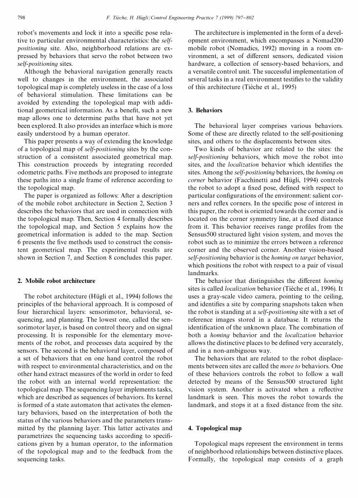
)t (Fig. 1).Assuming the robot is in pose A, a
ABis the rotation
angle that brings the turret to point towards the positionB, d
ABis the distance between the two positions A and B,
and bAB
is the rotation angle that aligns the turret to thepose B. A compounding operation is de"ned to expressa pose p
B, in term of a pose p
Aand a path w
ABlinking
pA
and pB. This compounding operation is denoted as:
pB"p
A= r
AB.
AxB
yB
uBB"A
xA
yA
uAB= A
dAB
aAB
bABB
"AxA#d
ABcos(u
A#a
AB)
yA#d
ABsin(u
A#a
AB)
uA#a
AB#b
ABB . (1)
Fig. 1. The path between two robot poses A and B is de"ned by thethree-dimensional vector (d
AB, a
AB, b
AB).
¹he compound operation is associative on the rightp"((p
0=w
1) =w
2)2
) =wk, and a sequence of com-
pounding operations is denoted as
p"p0
k=i/1
wi. (2)
In the same way, the inverse compounding operationpB
w PA"w
ABexpresses the path between two sites in
terms of their poses.
AdAB
aAB
bABB"A
xB
yB
uBB w A
xA
yA
uAB
"AJ(x
B#x
A)2#(y
B!y
A)2
arctan((yB#d
A)/(x
B#x
A)!u
Au
B!arctan((y
B!y
A)/(x
B!x
A))B . (3)
The inverse path can also be de"ned: w wAB
"wBA
. Thisimplies that if a path is known, the inverse path can becomputed. These compounding operators are close tothose used by Lu and Milios (1997), but di!er because thepaths are not de"ned in the same way.
6. Consistent geometrical map construction
Given the topological map and the associated informa-tion (the M measured geometrical paths wm
ij, and the
sequence of explored nodes + ) the geometrical map-building problem is to determine N!1 robot posespNi"(xN
i, yN
i, uN
i)t in a single coordinate system. One pose is
given a priori, and de"nes the origin of the system.Arbitrarily, the pose of the "rst explored node is chosen:o&(1)"(0, 0, 0)t.
Five methods of solving this problem are proposedbelow.
6.1. M1: Path integration along the exploration sequence
This method takes the nodes from the exploration listone by one, and "nds their poses by a simple integrationof successive paths.
F. Tieche, H. HuK gli/Control Engineering Practice 7 (1999) 797}802 799
Formally, the pose pL &(l) of the node &(l ) can be ex-pressed by compounding the origin of pose with thesequence of paths joining it to &(l):
pL &(l)"p&(1)l
=k/2
wm&(k~1)&(k) . (4)
As soon as circuits appear in the graph, nodes arevisited more than once; hence their poses are computedseveral times. In order to assign a single pose to eachnode, this method keeps only the "rst computed pose,and discards the remaining ones.
The complexity of M1 is O(M), where M is the numberof edges.
6.2. M2: Path integration without circuitsalong the exploration sequence
This method also takes the nodes from the explorationlist one by one. The pose is found by integration ofsuccessive paths, but when a circuit is closed on theexplored sequence, the integration is interrupted andrestarted from the "rst node belonging to the circuit. Inthis case, one pose is assigned to each node.
The complexity of M2 is O(M).
6.3. M3: Path integration along the minimum distance tree
This method determines the pose of a node by com-pounding the original pose with a sequence of paths. Inthe graph, several sequences possibly link the origin tothe current node. The chosen sequence is the one that hasthe minimum &&distance'' cost, de"ned as the sum of thedistance d of each path along the sequence. This method"nds the minimum spanning tree for a given root.
The complexity of M3 is O(MN).
6.4. M4: Path integration along the minimumorientation tree
This method determines the pose of a node by com-pounding the original pose with a sequence of paths. Inthe graph, several sequences may possibly link the originto the current node. The chosen sequence has the min-imum &&angular'' cost, de"ned as the sum of the angularvariation DaD#DbD of each path along the sequence. Thismethod "nds the minimum spanning tree for a given root.
The complexity of M4 is O(MN).
6.5. M5: Least-squares minimization
The least-squares method minimizes the error betweenthe measured paths wm
ijand the estimated paths wL
ij. The
function to be minimized is:
f (wL )"(wm!wL )t P(wm!wL )
where P is a matrix of weights.
The estimated relations can be expressed as a non-linear function of the estimated poses: wL
ij"pL
j@ pL
i.
Hence, the function to be minimized depends on theestimated robot poses f (pL ). It is the minimum or max-imum if its gradient is equal to zero.
+f (pL )"Lf (pL )LpL
"0. (5)
This provides a system of nonlinear equations with 3Nunknown variables. It is solved by means of the Newton}Raphson iterative method.
The complexity of M5 is O(N3).
7. Experimental results
This section presents the geometrical map reconstruc-tion for a real environment explored by a Nomad200mobile robot. The results of the "ve methods arecompared.
7.1. Exact map
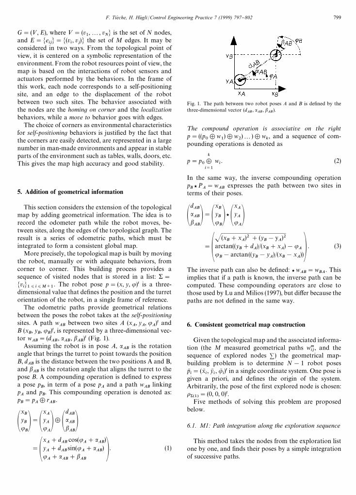
The real environment is composed of 28 homing sites(11 re#ex corners, 17 salient corners), distributed overa 10]12 m surface (Fig. 2a). In order to compare thereconstructed maps of robot poses pL
i"(xL
i, yL
i, uL
i)t, an
exact map of the robot poses pei"(xe
i, ye
i, ue
i)t is mea-
sured. It is constructed in two steps. First, the corners aremapped by means of a precise measurement. Then, therobot pose with respect to a corner is established, byaveraging several measurements. Finally, these values areadded to the precise map of the corners, in order toobtain the exact map of the robot poses.
7.2. Comparison of exact and estimated maps
After a rigid alignment transformation, the exact andthe estimated maps are compared. The di!erence be-tween the two maps is expressed as the root mean squareof the distance *d, and the di!erence of orientation *u,between corresponding site poses.
*d"S1
N+N
(xei!xL
i)2#(ye
i!yL
i)2 (6)
*u"S1
N+N
(uei!uL
i)2 . (7)
7.3. List of explored paths
The paths were measured by odometers while therobot was exploring its environment. Seventy-two pathsbetween the twenty-eight self-positioning sites were mea-sured. Fig. 2b shows the compounding of the startingpose with the 72 paths, along the sequence of exploration.
800 F. Tieche, H. HuK gli/Control Engineering Practice 7 (1999) 797}802
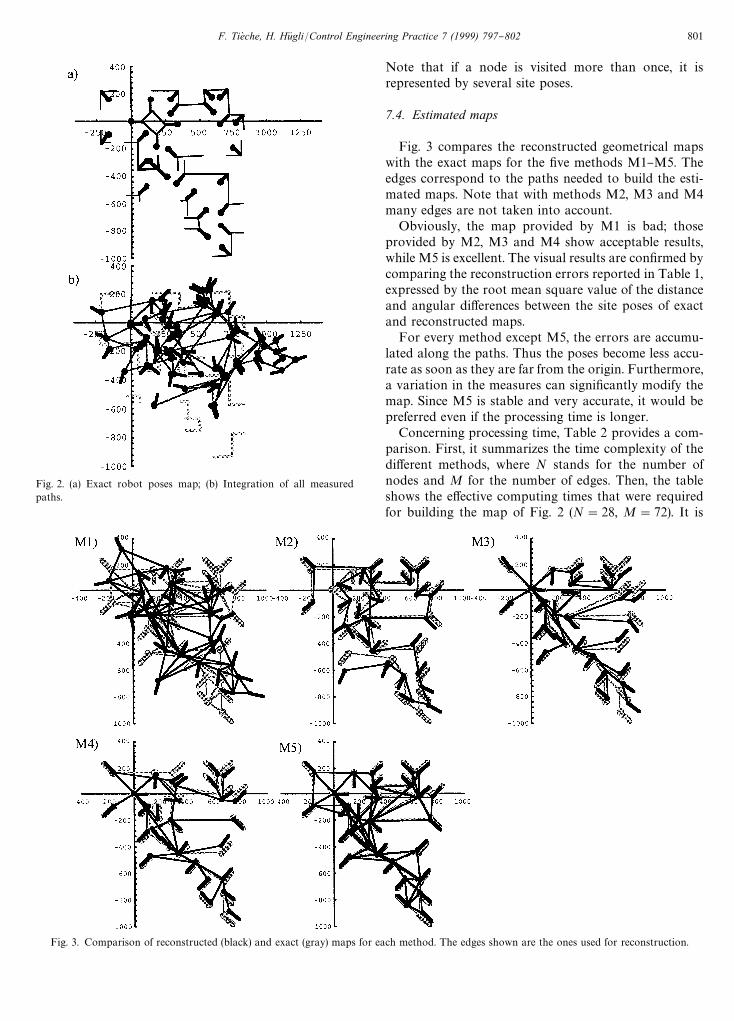
Fig. 3. Comparison of reconstructed (black) and exact (gray) maps for each method. The edges shown are the ones used for reconstruction.
Fig. 2. (a) Exact robot poses map; (b) Integration of all measuredpaths.
Note that if a node is visited more than once, it isrepresented by several site poses.
7.4. Estimated maps
Fig. 3 compares the reconstructed geometrical mapswith the exact maps for the "ve methods M1}M5. Theedges correspond to the paths needed to build the esti-mated maps. Note that with methods M2, M3 and M4many edges are not taken into account.
Obviously, the map provided by M1 is bad; thoseprovided by M2, M3 and M4 show acceptable results,while M5 is excellent. The visual results are con"rmed bycomparing the reconstruction errors reported in Table 1,expressed by the root mean square value of the distanceand angular di!erences between the site poses of exactand reconstructed maps.
For every method except M5, the errors are accumu-lated along the paths. Thus the poses become less accu-rate as soon as they are far from the origin. Furthermore,a variation in the measures can signi"cantly modify themap. Since M5 is stable and very accurate, it would bepreferred even if the processing time is longer.
Concerning processing time, Table 2 provides a com-parison. First, it summarizes the time complexity of thedi!erent methods, where N stands for the number ofnodes and M for the number of edges. Then, the tableshows the e!ective computing times that were requiredfor building the map of Fig. 2 (N"28, M"72). It is
F. Tieche, H. HuK gli/Control Engineering Practice 7 (1999) 797}802 801
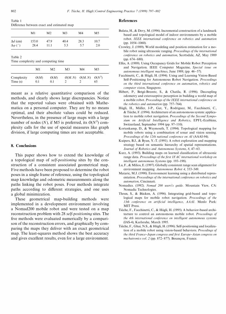
Table 1Di!erence between exact and estimated map
M1 M2 M3 M4 M5
*d (cm) 153.0 47.9 40.4 28.3 10.7*u ( 3 ) 28.4 11.1 5.3 5.7 2.0
Table 2Time complexity and computing time
M1 M2 M3 M4 M5
Complexity O(M) O(M) O(M.N) O(M.N) O(N3)Time (s) 0.1 0.1 2 2 65
meant as a relative quantitative comparison of themethods, and clearly shows large discrepancies. Noticethat the reported values were obtained with Mathe-matica on a personal computer. They are by no meansoptimal, and their absolute values could be reduced.Nevertheless, in the presence of large maps with a largenumber of nodes (N ), if M5 is preferred, its O(N3) com-plexity calls for the use of special measures like graphdivision, if large computing times are not acceptable.
8. Conclusions
This paper shows how to extend the knowledge ofa topological map of self-positioning sites by the con-struction of a consistent associated geometrical map.Five methods have been proposed to determine the robotposes in a single frame of reference, using the topologicalmap knowledge and odometric measurements along thepaths linking the robot poses. Four methods integratepaths according to di!erent strategies, and one usesa global minimization.
These geometrical map-building methods wereimplemented in a development environment involvinga Nomad200 mobile robot and were tested on a mapreconstruction problem with 28 self-positioning sites. The"ve methods were evaluated numerically by a compari-son of the reconstruction errors, and graphically by com-paring the maps they deliver with an exact geometricalmap. The least-squares method shows the best accuracyand gives excellent results, even for a large environment.
References
Bulata, H., & Devy, M. (1996). Incremental construction of a landmarkbased and topological model of indoor environments by a mobilerobot. IEEE international conference on robotics and automation(pp. 1054}1060).
Crowley, J. (1989). World modeling and position estimation for a mo-bile robot using ultrasonic ranging. Proceedings of the internationalconference on robotics and automation, Scottsdale, AZ, May 1989(pp. 674}680).
Elfes, A. (1989). Using Occupancy Grids for Mobile Robot Perceptionand Navigation. IEEE Computer Magazine, Special issue onautonomous intelligent machines, June 1989, (pp. 46}57).
Facchinetti, C., & HuK gli, H. (1994). Using and Learning Vision-BasedSelf-Positioning for Autonomous Robot Navigation. Proceedingson the third international conference on automation, robotics andcomputer vision, Singapore.
HeH bert, P., BetgeH -Brezetz, S., & Chatila, R. (1996). Decouplingodometry and exteroceptive perception in building a world map ofa mobile robot. Proceedings of the IEEE international conference onthe robotics and automation (pp. 757}764).
HuK gli, H., MuK ller, J-P., Gat, Y., Rodriguez, M., Facchinetti, C.,& Tieche, F. (1994). Architecture of an autonomous system: applica-tion to mobile robot navigation. Proceedings of the Second Sympo-sium on Arti,cial Intelligence and Robotics, EPFL-Ecublens,Switzerland, September 1994 (pp. 97}110).
Kortenkamp, D., & Weymouth, T. (1994). Topological mapping formobile robots using a combination of sonar and vision sensing.Proceedings of the 12th national conference on AI (AAAI-94).
Kuipers, B.J., & Byun, Y.-T. (1991). A robot exploration and mappingstrategy based on semantic hierarchy of spatial representations.Journal of Robotics and Autonomous Systems, 8, 47}63.
Kurz, A. (1993). Building maps on learned classi"cation of ultrasonicrange data. Proceedings of the ,rst IFAC international workshop onintelligent autonomous Systems (pp. 193}198).
Lu, F., & Milios, E. (1997). Globally consistent range scan alignment forenvironment mapping. Autonomous Robot 4, 333}349.
Mataric, M.J. (1990). Environment learning using a distributed repres-entation. Proceedings of the international conference on robotics andautomation, Cincinnati.
Nomadics. (1992). Nomad 200 users1s guide. Mountain View, CA:Nomadic Technologies.
Thrun, S., & BuK cken, A. (1996). Integrating grid-based and topo-logical maps for mobile robot navigation. Proceedings of the13th conference on arti,cial intelligence, AAAI. Menlo Park:MIT Press.
Tieche, F., Facchinetti, C., & HuK gli, H. (1995). A behavior-based archi-tecture to control an autonomous mobile robot. Proceedings ofthe 4th international conference on intelligent autonomous systems(IAS-4), Karlsruhe, March 1995.
Tieche, F., Ghai, N.S., & HuK gli, H. (1996). Self-positioning and localiza-tion of a mobile robot using vision-based behaviors. Procedings ofthe third France}Japan congress and ,rst Europe}Asian congress onmechatronics vol. 2 (pp. 872}877). Besanion, France.
802 F. Tieche, H. HuK gli/Control Engineering Practice 7 (1999) 797}802


![STATISTICAL PROPERTIES OF TOPOLOGICAL … PROPERTIES OF TOPOLOGICAL COLLET–ECKMANN MAPS 137 also [25,44,37]. For a rational map satisfying the TCE condition, the minimal exponent](https://img.pdfslide.net/doc/110x75/5b04fa8a7f8b9a41528d3fe7/statistical-properties-of-topological-properties-of-topological-colleteckmann.jpg)