Embed Size (px)
Citation preview

Mot
herb
oard
A8N-SLIDeluxe

i ii ii ii ii i
Copyright © 2004 ASUSTeK COMPUTER INC. All Rights Reserved.No part of this manual, including the products and software described in it, may be reproduced,transmitted, transcribed, stored in a retrieval system, or translated into any language in any formor by any means, except documentation kept by the purchaser for backup purposes, without theexpress written permission of ASUSTeK COMPUTER INC. (“ASUS”).
Product warranty or service will not be extended if: (1) the product is repaired, modified oraltered, unless such repair, modification of alteration is authorized in writing by ASUS; or (2)the serial number of the product is defaced or missing.
ASUS PROVIDES THIS MANUAL “AS IS” WITHOUT WARRANTY OF ANY KIND, EITHEREXPRESS OR IMPLIED, INCLUDING BUT NOT LIMITED TO THE IMPLIED WARRANTIESOR CONDITIONS OF MERCHANTABILITY OR FITNESS FOR A PARTICULAR PURPOSE.IN NO EVENT SHALL ASUS, ITS DIRECTORS, OFFICERS, EMPLOYEES OR AGENTS BELIABLE FOR ANY INDIRECT, SPECIAL, INCIDENTAL, OR CONSEQUENTIAL DAMAGES(INCLUDING DAMAGES FOR LOSS OF PROFITS, LOSS OF BUSINESS, LOSS OF USEOR DATA, INTERRUPTION OF BUSINESS AND THE LIKE), EVEN IF ASUS HAS BEENADVISED OF THE POSSIBILITY OF SUCH DAMAGES ARISING FROM ANY DEFECT ORERROR IN THIS MANUAL OR PRODUCT.
SPECIFICATIONS AND INFORMATION CONTAINED IN THIS MANUAL ARE FURNISHEDFOR INFORMATIONAL USE ONLY, AND ARE SUBJECT TO CHANGE AT ANY TIMEWITHOUT NOTICE, AND SHOULD NOT BE CONSTRUED AS A COMMITMENT BY ASUS.ASUS ASSUMES NO RESPONSIBILITY OR LIABILITY FOR ANY ERRORS ORINACCURACIES THAT MAY APPEAR IN THIS MANUAL, INCLUDING THE PRODUCTSAND SOFTWARE DESCRIBED IN IT.
Products and corporate names appearing in this manual may or may not be registeredtrademarks or copyrights of their respective companies, and are used only for identification orexplanation and to the owners’ benefit, without intent to infringe.
E1889E1889E1889E1889E1889
Revised Edit ion V2Revised Edit ion V2Revised Edit ion V2Revised Edit ion V2Revised Edit ion V2November 2004November 2004November 2004November 2004November 2004

i i ii i ii i ii i ii i i
Contents
Notices ............................................................................................... vii
Safety information ............................................................................ viii
About this guide ................................................................................. ix
How this guide is organized .................................................... ix
Where to find more information .............................................. ix
Conventions used in this guide ................................................ x
Typography .......................................................................................... x
A8N-SLI Deluxe specifications summary ............................................. xi
Chapter 1: Product introductionChapter 1: Product introductionChapter 1: Product introductionChapter 1: Product introductionChapter 1: Product introduction
1.1 Welcome! .............................................................................. 1-1
1.2 Package contents ................................................................. 1-1
1.3 Special features .................................................................... 1-2
1.3.1 Product highlights ................................................... 1-2
1.3.2 ASUS Proactive features ........................................ 1-5
1.3.3 Innovative ASUS features ....................................... 1-6
Chapter 2: Hardware informationChapter 2: Hardware informationChapter 2: Hardware informationChapter 2: Hardware informationChapter 2: Hardware information
2.1 Before you proceed .............................................................. 2-1
2.2 Motherboard overview .......................................................... 2-2
2.2.1 Placement direction ................................................ 2-2
2.2.2 Screw holes ............................................................ 2-2
2.2.3 Motherboard layout ................................................ 2-3
2.2.4 Layout Contents ..................................................... 2-4
2.3 Central Processing Unit (CPU) .............................................. 2-6
2.3.1 Overview ................................................................. 2-6
2.3.2 Installling the CPU ................................................... 2-6
2.3.3 Installing the heatsink and fan ................................ 2-8
2.4 System memory ................................................................. 2-11
2.4.1 Overview ............................................................... 2-11
2.4.2 Memory Configurations ......................................... 2-11
2.4.3 Installing a DIMM ................................................... 2-13
2.4.4 Removing a DIMM ................................................. 2-13
2.5 Expansion slots ................................................................... 2-14
2.5.1 Installing an expansion card .................................. 2-14
i vi vi vi vi v
Contents
2.5.2 Configuring an expansion card .............................. 2-14
2.5.3 Interrupt assignments .......................................... 2-15
2.5.4 PCI slots ................................................................ 2-16
2.5.5 Two PCI Express x16 slots ................................... 2-16
2.5.6 PCI Express x1 slot ............................................... 2-16
2.6 Jumpers .............................................................................. 2-17
2.7 Connectors ......................................................................... 2-18
2.7.1 Rear panel connectors .......................................... 2-18
2.7.2 Internal connectors ............................................... 2-20
Chapter 3: Powering upChapter 3: Powering upChapter 3: Powering upChapter 3: Powering upChapter 3: Powering up
3.1 Starting up for the first time ................................................ 3-1
3.2 Powering off the computer .................................................. 3-2
3.2.1 Using the OS shut down function ........................... 3-2
3.2.2 Using the dual function power switch .................... 3-2
3.3 ASUS POST Reporter™ .......................................................... 3-3
3.3.1 Vocal POST messages ............................................ 3-3
3.3.2 Winbond Voice Editor ............................................. 3-5
Chapter 4: BIOS setupChapter 4: BIOS setupChapter 4: BIOS setupChapter 4: BIOS setupChapter 4: BIOS setup
4.1 Managing and updating your BIOS ........................................ 4-1
4.1.1 Creating a bootable floppy disk .............................. 4-1
4.1.2 Updating the BIOS .................................................. 4-2
4.1.3 Saving the current BIOS file .................................... 4-4
4.1.4 ASUS CrashFree BIOS 2 utility ................................ 4-5
4.1.5 ASUS EZ Flash utility .............................................. 4-7
4.1.6 ASUS Update utility ................................................ 4-8
4.2 BIOS setup program ........................................................... 4-11
4.2.1 BIOS menu screen ................................................. 4-12
4.2.2 Menu bar ............................................................... 4-12
4.2.3 Legend bar ........................................................... 4-13
4.2.4 Menu items ........................................................... 4-13
4.2.5 Sub-menu items ................................................... 4-13
4.2.6 Configuration fields .............................................. 4-13
4.2.8 General help .......................................................... 4-14
4.2.7 Pop-up window ..................................................... 4-14

vvvvv
Contents
4.3 Main menu .......................................................................... 4-15
4.3.1 System Time......................................................... 4-15
4.3.2 System Date ......................................................... 4-15
4.3.3 Language .............................................................. 4-15
4.3.4 Legacy Diskette A ................................................ 4-15
4.3.5 Primary and Secondary IDE Master/Slave ............. 4-16
4.3.5 First, Second, Third, Fourth SATA Master ............ 4-18
4.3.7 HDD SMART Monitoring ........................................ 4-19
4.3.8 Installed Memory .................................................. 4-19
4.4 Advanced menu .................................................................. 4-20
4.4.1 CPU Configuration ................................................. 4-20
4.4.2 PCIPnP ................................................................... 4-23
4.4.3 Onboard Devices Configuration ............................ 4-24
4.4.4 JumperFree Configuration .................................... 4-29
4.4.5 LAN Cable Status ................................................. 4-31
4.4.6 PEG Link Mode ...................................................... 4-32
4.4.7 Speech Configuration ........................................... 4-33
4.4.8 Instant Music ........................................................ 4-34
4.4.9 SLI mode ............................................................... 4-34
4.5 Power menu ........................................................................ 4-35
4.5.1 ACPI Suspend Type............................................... 4-35
4.5.2 ACPI APIC Support ................................................ 4-35
4.5.3 APM Configuration ................................................ 4-36
4.5.4 Hardware Monitor ................................................. 4-38
4.6 Boot menu .......................................................................... 4-40
4.6.1 Boot Device Priority .............................................. 4-40
4.6.2 Removable Drives ................................................. 4-41
4.6.3 Hard Disk Drives ................................................... 4-41
4.6.4 CDROM Drives ....................................................... 4-42
4.6.5 Boot Settings Configuration ................................. 4-42
4.6.6 Security ................................................................ 4-44
4.7 Exit menu ........................................................................... 4-46
Chapter 5: Software supportChapter 5: Software supportChapter 5: Software supportChapter 5: Software supportChapter 5: Software support
5.1 Installing an operating system ............................................. 5-1
v iv iv iv iv i
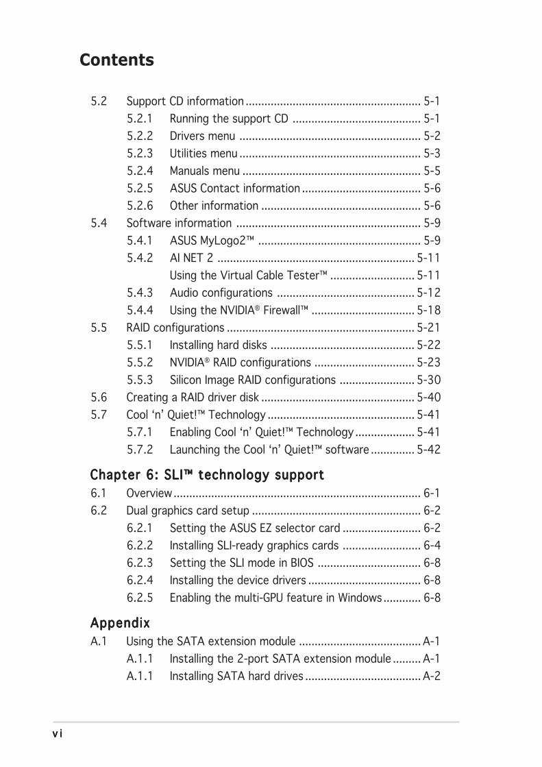
5.2 Support CD information ........................................................ 5-1
5.2.1 Running the support CD ......................................... 5-1
5.2.2 Drivers menu .......................................................... 5-2
5.2.3 Utilities menu .......................................................... 5-3
5.2.4 Manuals menu ......................................................... 5-5
5.2.5 ASUS Contact information ...................................... 5-6
5.2.6 Other information ................................................... 5-6
5.4 Software information ........................................................... 5-9
5.4.1 ASUS MyLogo2™ .................................................... 5-9
5.4.2 AI NET 2 ............................................................... 5-11
Using the Virtual Cable Tester™ ........................... 5-11
5.4.3 Audio configurations ............................................ 5-12
5.4.4 Using the NVIDIA® Firewall™ ................................. 5-18
5.5 RAID configurations ............................................................ 5-21
5.5.1 Installing hard disks .............................................. 5-22
5.5.2 NVIDIA® RAID configurations ................................ 5-23
5.5.3 Silicon Image RAID configurations ........................ 5-30
5.6 Creating a RAID driver disk ................................................. 5-40
5.7 Cool ‘n’ Quiet!™ Technology ............................................... 5-41
5.7.1 Enabling Cool ‘n’ Quiet!™ Technology ................... 5-41
5.7.2 Launching the Cool ‘n’ Quiet!™ software .............. 5-42
Chapter 6: SLI™ technology supportChapter 6: SLI™ technology supportChapter 6: SLI™ technology supportChapter 6: SLI™ technology supportChapter 6: SLI™ technology support
6.1 Overview............................................................................... 6-1
6.2 Dual graphics card setup ...................................................... 6-2
6.2.1 Setting the ASUS EZ selector card ......................... 6-2
6.2.2 Installing SLI-ready graphics cards ......................... 6-4
6.2.3 Setting the SLI mode in BIOS ................................. 6-8
6.2.4 Installing the device drivers .................................... 6-8
6.2.5 Enabling the multi-GPU feature in Windows............ 6-8
AppendixAppendixAppendixAppendixAppendix
A.1 Using the SATA extension module ....................................... A-1
A.1.1 Installing the 2-port SATA extension module ......... A-1
A.1.1 Installing SATA hard drives ..................................... A-2
Contents

v i iv i iv i iv i iv i i
Notices
Federal Communications Commission StatementFederal Communications Commission StatementFederal Communications Commission StatementFederal Communications Commission StatementFederal Communications Commission Statement
This device complies with Part 15 of the FCC Rules. Operation is subject tothe following two conditions:
• This device may not cause harmful interference, and
• This device must accept any interference received including interferencethat may cause undesired operation.
This equipment has been tested and found to comply with the limits for aClass B digital device, pursuant to Part 15 of the FCC Rules. These limits aredesigned to provide reasonable protection against harmful interference in aresidential installation. This equipment generates, uses and can radiate radiofrequency energy and, if not installed and used in accordance withmanufacturer’s instructions, may cause harmful interference to radiocommunications. However, there is no guarantee that interference will notoccur in a particular installation. If this equipment does cause harmfulinterference to radio or television reception, which can be determined byturning the equipment off and on, the user is encouraged to try to correctthe interference by one or more of the following measures:
• Reorient or relocate the receiving antenna.
• Increase the separation between the equipment and receiver.
• Connect the equipment to an outlet on a circuit different from that towhich the receiver is connected.
• Consult the dealer or an experienced radio/TV technician for help.
Canadian Department of Communications StatementCanadian Department of Communications StatementCanadian Department of Communications StatementCanadian Department of Communications StatementCanadian Department of Communications Statement
This digital apparatus does not exceed the Class B limits for radio noiseemissions from digital apparatus set out in the Radio InterferenceRegulations of the Canadian Department of Communications.
This class B digital apparatus complies with CanadianThis class B digital apparatus complies with CanadianThis class B digital apparatus complies with CanadianThis class B digital apparatus complies with CanadianThis class B digital apparatus complies with CanadianICES-003.ICES-003.ICES-003.ICES-003.ICES-003.
The use of shielded cables for connection of the monitor to the graphicscard is required to assure compliance with FCC regulations. Changes ormodifications to this unit not expressly approved by the partyresponsible for compliance could void the user’s authority to operatethis equipment.

v i i iv i i iv i i iv i i iv i i i
Safety information
Electrical safetyElectrical safetyElectrical safetyElectrical safetyElectrical safety
• To prevent electrical shock hazard, disconnect the power cable from theelectrical outlet before relocating the system.
• When adding or removing devices to or from the system, ensure that thepower cables for the devices are unplugged before the signal cables areconnected. If possible, disconnect all power cables from the existingsystem before you add a device.
• Before connecting or removing signal cables from the motherboard,ensure that all power cables are unplugged.
• Seek professional assistance before using an adapter or extension cord.These devices could interrupt the grounding circuit.
• Make sure that your power supply is set to the correct voltage in yourarea. If you are not sure about the voltage of the electrical outlet you areusing, contact your local power company.
• If the power supply is broken, do not try to fix it by yourself. Contact aqualified service technician or your retailer.
Operation safetyOperation safetyOperation safetyOperation safetyOperation safety
• Before installing the motherboard and adding devices on it, carefully readall the manuals that came with the package.
• Before using the product, make sure all cables are correctly connectedand the power cables are not damaged. If you detect any damage,contact your dealer immediately.
• To avoid short circuits, keep paper clips, screws, and staples away fromconnectors, slots, sockets and circuitry.
• Avoid dust, humidity, and temperature extremes. Do not place theproduct in any area where it may become wet.
• Place the product on a stable surface.
• If you encounter technical problems with the product, contact a qualifiedservice technician or your retailer.
i xi xi xi xi x
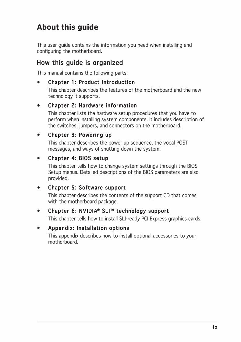
About this guide
This user guide contains the information you need when installing andconfiguring the motherboard.
How this guide is organizedHow this guide is organizedHow this guide is organizedHow this guide is organizedHow this guide is organized
This manual contains the following parts:
••••• Chapter 1: Product introduct ionChapter 1: Product introduct ionChapter 1: Product introduct ionChapter 1: Product introduct ionChapter 1: Product introduct ion
This chapter describes the features of the motherboard and the newtechnology it supports.
••••• Chapter 2: Hardware informat ionChapter 2: Hardware informat ionChapter 2: Hardware informat ionChapter 2: Hardware informat ionChapter 2: Hardware informat ion
This chapter lists the hardware setup procedures that you have toperform when installing system components. It includes description ofthe switches, jumpers, and connectors on the motherboard.
••••• Chapter 3: Power ing upChapter 3: Power ing upChapter 3: Power ing upChapter 3: Power ing upChapter 3: Power ing up
This chapter describes the power up sequence, the vocal POSTmessages, and ways of shutting down the system.
••••• Chapter 4: B IOS setupChapter 4: B IOS setupChapter 4: B IOS setupChapter 4: B IOS setupChapter 4: B IOS setup
This chapter tells how to change system settings through the BIOSSetup menus. Detailed descriptions of the BIOS parameters are alsoprovided.
••••• Chapter 5: Software supportChapter 5: Software supportChapter 5: Software supportChapter 5: Software supportChapter 5: Software support
This chapter describes the contents of the support CD that comeswith the motherboard package.
••••• Chapter 6: NVIDIAChapter 6: NVIDIAChapter 6: NVIDIAChapter 6: NVIDIAChapter 6: NVIDIA®®®®® SLI™ technology support SLI™ technology support SLI™ technology support SLI™ technology support SLI™ technology support
This chapter tells how to install SLI-ready PCI Express graphics cards.
••••• Appendix: Insta l lat ion opt ionsAppendix: Insta l lat ion opt ionsAppendix: Insta l lat ion opt ionsAppendix: Insta l lat ion opt ionsAppendix: Insta l lat ion opt ions
This appendix describes how to install optional accessories to yourmotherboard.
xxxxx
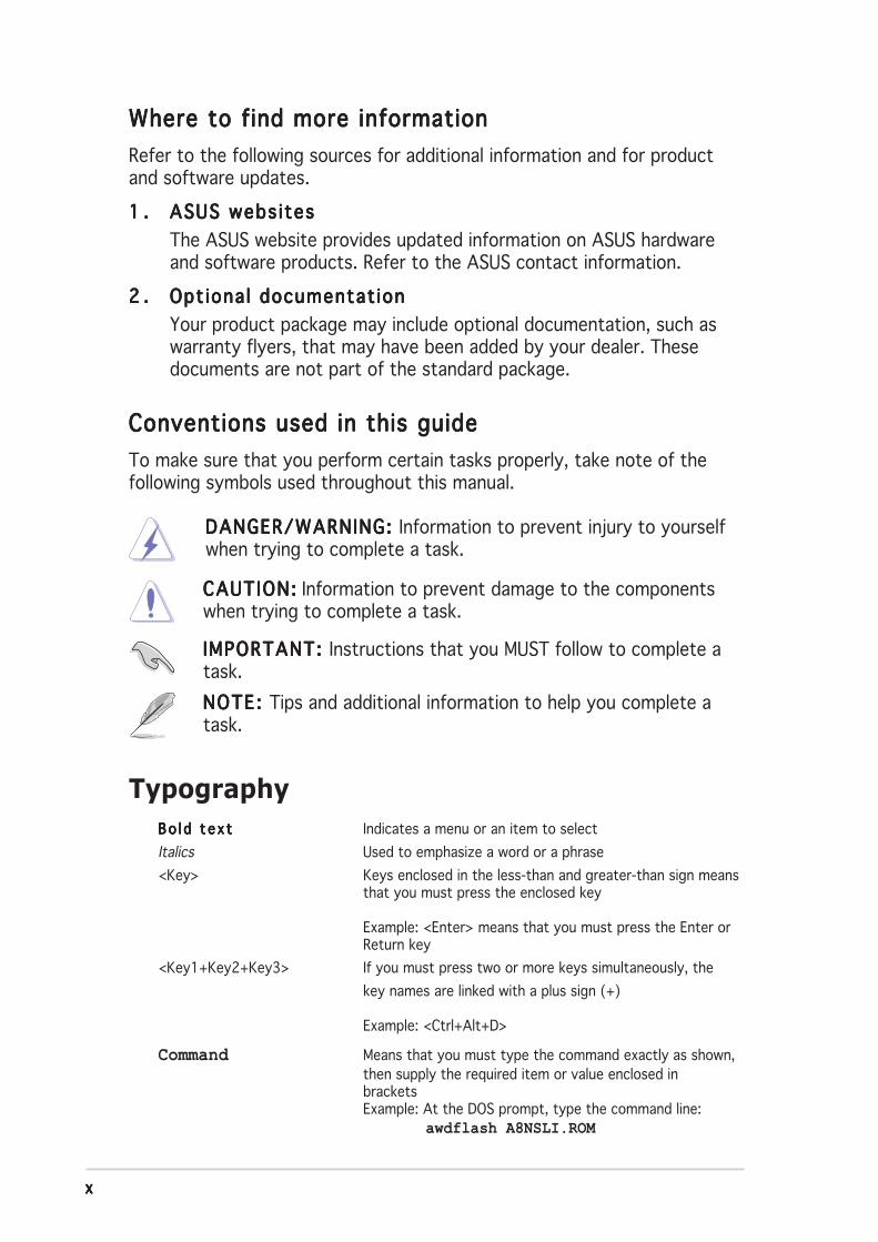
Conventions used in this guideConventions used in this guideConventions used in this guideConventions used in this guideConventions used in this guide
To make sure that you perform certain tasks properly, take note of thefollowing symbols used throughout this manual.
Typography
DANGER/WARNING: DANGER/WARNING: DANGER/WARNING: DANGER/WARNING: DANGER/WARNING: Information to prevent injury to yourselfwhen trying to complete a task.
CAUTION:CAUTION:CAUTION:CAUTION:CAUTION: Information to prevent damage to the componentswhen trying to complete a task.
NOTE: NOTE: NOTE: NOTE: NOTE: Tips and additional information to help you complete atask.
IMPORTANT: IMPORTANT: IMPORTANT: IMPORTANT: IMPORTANT: Instructions that you MUST follow to complete atask.
Bo l d t e x tBo l d t e x tBo l d t e x tBo l d t e x tBo l d t e x t Indicates a menu or an item to select
Italics Used to emphasize a word or a phrase
<Key> Keys enclosed in the less-than and greater-than sign meansthat you must press the enclosed key
Example: <Enter> means that you must press the Enter orReturn key
<Key1+Key2+Key3> If you must press two or more keys simultaneously, the
key names are linked with a plus sign (+)
Example: <Ctrl+Alt+D>
Command Means that you must type the command exactly as shown,then supply the required item or value enclosed inbracketsExample: At the DOS prompt, type the command line: awdflash A8NSLI.ROM
Where to find more informationWhere to find more informationWhere to find more informationWhere to find more informationWhere to find more information
Refer to the following sources for additional information and for productand software updates.
1 .1 .1 .1 .1 . ASUS webs itesASUS webs itesASUS webs itesASUS webs itesASUS webs ites
The ASUS website provides updated information on ASUS hardwareand software products. Refer to the ASUS contact information.
2 .2 .2 .2 .2 . Opt ional documentat ionOpt ional documentat ionOpt ional documentat ionOpt ional documentat ionOpt ional documentat ion
Your product package may include optional documentation, such aswarranty flyers, that may have been added by your dealer. Thesedocuments are not part of the standard package.
x ix ix ix ix i
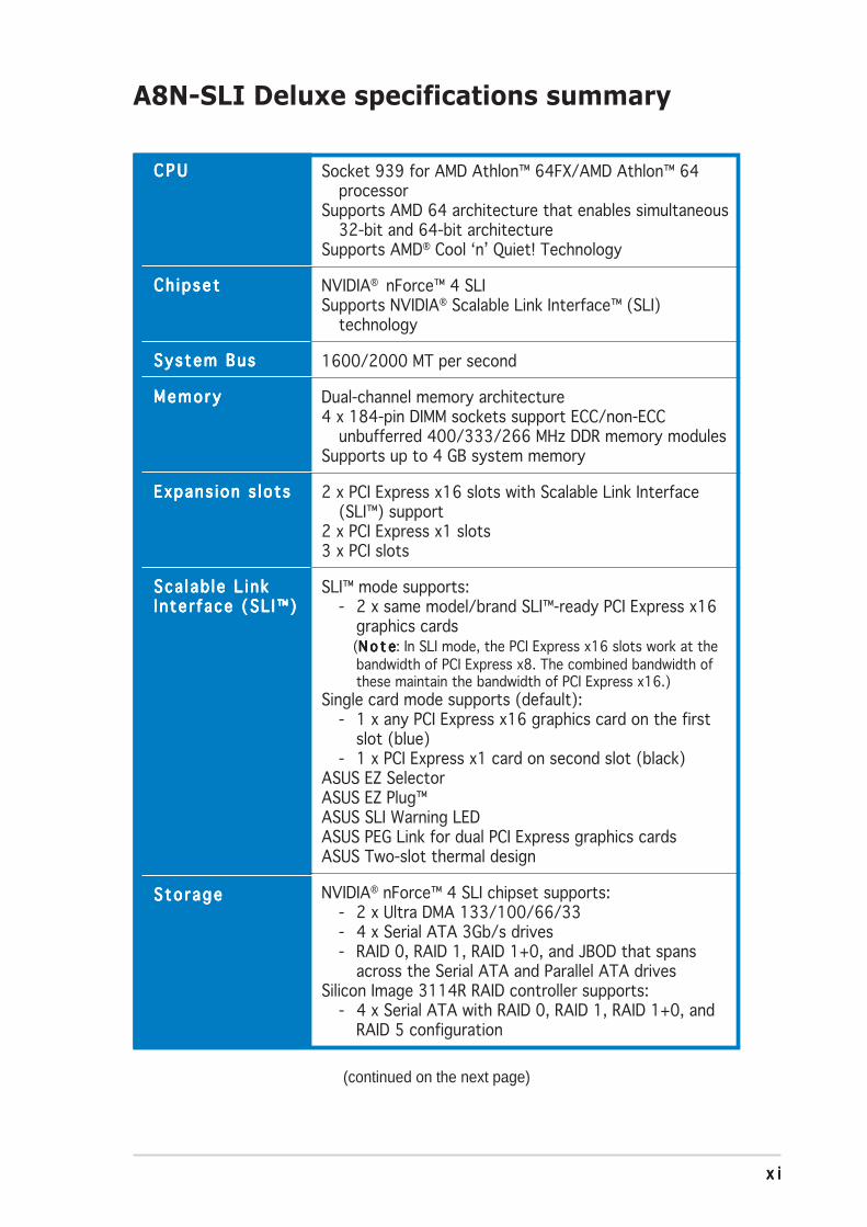
A8N-SLI Deluxe specifications summary
(continued on the next page)
C P UC P UC P UC P UC P U
Ch ipsetCh ipsetCh ipsetCh ipsetCh ipset
System BusSystem BusSystem BusSystem BusSystem Bus
MemoryMemoryMemoryMemoryMemory
Expans ion s lotsExpans ion s lotsExpans ion s lotsExpans ion s lotsExpans ion s lots
Sca lab le L inkSca lab le L inkSca lab le L inkSca lab le L inkSca lab le L inkInter face (SL I™)Inter face (SL I™)Inter face (SL I™)Inter face (SL I™)Inter face (SL I™)
Sto rageSto rageSto rageSto rageSto rage
Socket 939 for AMD Athlon™ 64FX/AMD Athlon™ 64processor
Supports AMD 64 architecture that enables simultaneous32-bit and 64-bit architecture
Supports AMD® Cool ‘n’ Quiet! Technology
NVIDIA® nForce™ 4 SLISupports NVIDIA® Scalable Link Interface™ (SLI)
technology
1600/2000 MT per second
Dual-channel memory architecture4 x 184-pin DIMM sockets support ECC/non-ECC
unbufferred 400/333/266 MHz DDR memory modulesSupports up to 4 GB system memory
2 x PCI Express x16 slots with Scalable Link Interface(SLI™) support
2 x PCI Express x1 slots3 x PCI slots
SLI™ mode supports:- 2 x same model/brand SLI™-ready PCI Express x16
graphics cards (N o t eN o t eN o t eN o t eN o t e: In SLI mode, the PCI Express x16 slots work at the
bandwidth of PCI Express x8. The combined bandwidth ofthese maintain the bandwidth of PCI Express x16.)
Single card mode supports (default):- 1 x any PCI Express x16 graphics card on the first
slot (blue)- 1 x PCI Express x1 card on second slot (black)
ASUS EZ SelectorASUS EZ Plug™ASUS SLI Warning LEDASUS PEG Link for dual PCI Express graphics cardsASUS Two-slot thermal design
NVIDIA® nForce™ 4 SLI chipset supports:- 2 x Ultra DMA 133/100/66/33- 4 x Serial ATA 3Gb/s drives- RAID 0, RAID 1, RAID 1+0, and JBOD that spans
across the Serial ATA and Parallel ATA drivesSilicon Image 3114R RAID controller supports:
- 4 x Serial ATA with RAID 0, RAID 1, RAID 1+0, andRAID 5 configuration
x i ix i ix i ix i ix i i
A8N-SLI Deluxe specifications summary
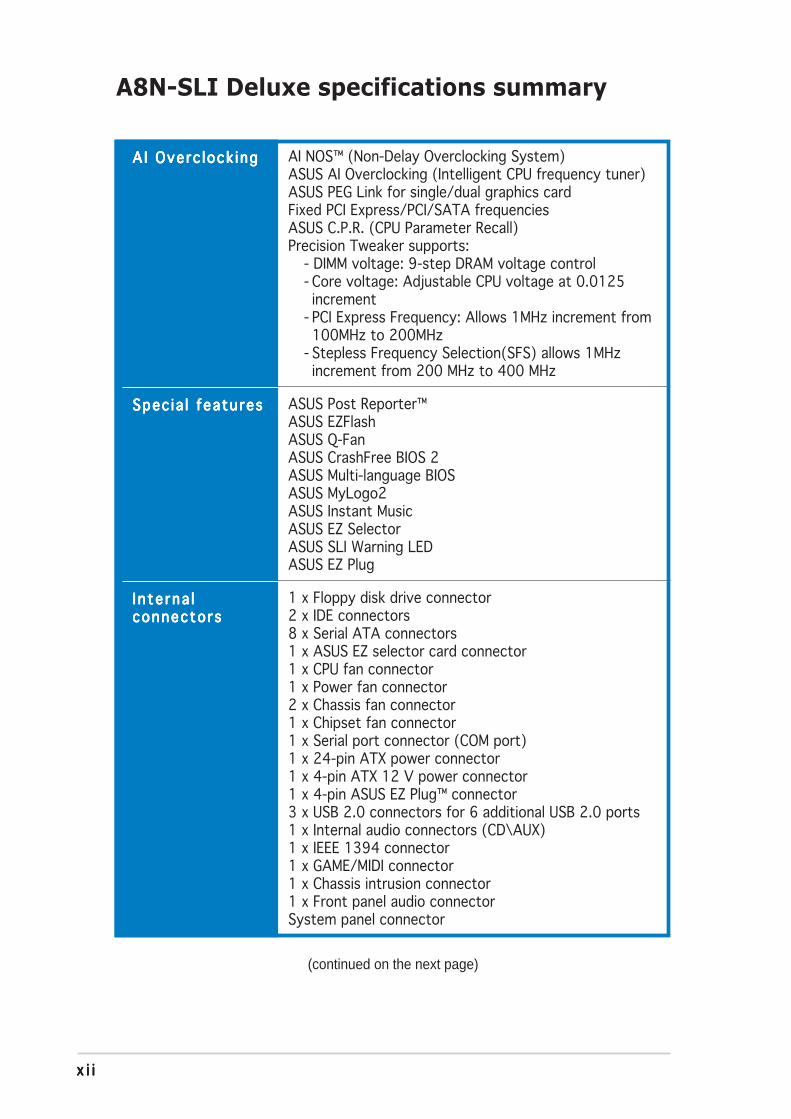
AI Overc lock ingA I Overc lock ingA I Overc lock ingA I Overc lock ingA I Overc lock ing
Spec ia l featuresSpec ia l featuresSpec ia l featuresSpec ia l featuresSpec ia l features
In te rna lI n te rna lI n te rna lI n te rna lI n te rna lconnectorsconnectorsconnectorsconnectorsconnectors
AI NOS™ (Non-Delay Overclocking System)ASUS AI Overclocking (Intelligent CPU frequency tuner)ASUS PEG Link for single/dual graphics cardFixed PCI Express/PCI/SATA frequenciesASUS C.P.R. (CPU Parameter Recall)Precision Tweaker supports:
- DIMM voltage: 9-step DRAM voltage control- Core voltage: Adjustable CPU voltage at 0.0125increment
- PCI Express Frequency: Allows 1MHz increment from100MHz to 200MHz
- Stepless Frequency Selection(SFS) allows 1MHzincrement from 200 MHz to 400 MHz
ASUS Post Reporter™ASUS EZFlashASUS Q-FanASUS CrashFree BIOS 2ASUS Multi-language BIOSASUS MyLogo2ASUS Instant MusicASUS EZ SelectorASUS SLI Warning LEDASUS EZ Plug
1 x Floppy disk drive connector2 x IDE connectors8 x Serial ATA connectors1 x ASUS EZ selector card connector1 x CPU fan connector1 x Power fan connector2 x Chassis fan connector1 x Chipset fan connector1 x Serial port connector (COM port)1 x 24-pin ATX power connector1 x 4-pin ATX 12 V power connector1 x 4-pin ASUS EZ Plug™ connector3 x USB 2.0 connectors for 6 additional USB 2.0 ports1 x Internal audio connectors (CD\AUX)1 x IEEE 1394 connector1 x GAME/MIDI connector1 x Chassis intrusion connector1 x Front panel audio connectorSystem panel connector
(continued on the next page)
x i i ix i i ix i i ix i i ix i i i
A8N-SLI Deluxe specifications summary
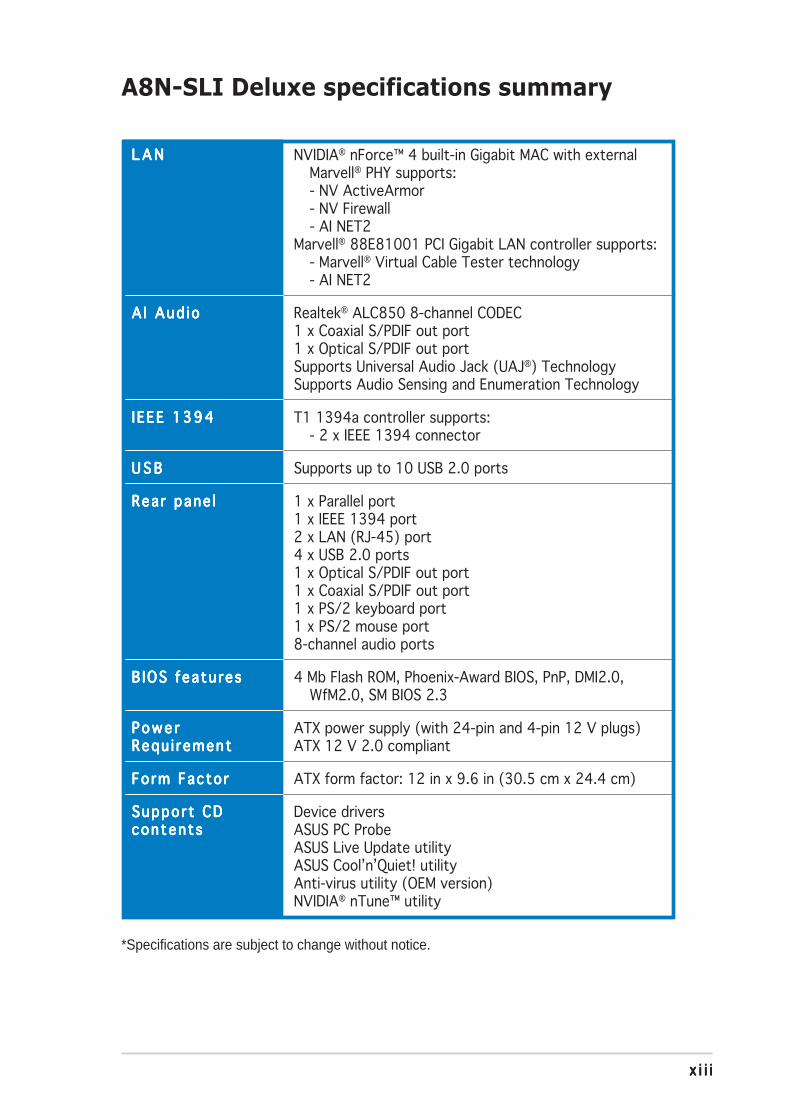
L A NL A NL A NL A NL A N
A I Aud ioA I Aud ioA I Aud ioA I Aud ioA I Aud io
IEEE 1394IEEE 1394IEEE 1394IEEE 1394IEEE 1394
U S BU S BU S BU S BU S B
Rear pane lRear pane lRear pane lRear pane lRear pane l
B IOS featuresB IOS featuresB IOS featuresB IOS featuresB IOS features
Powe rPowe rPowe rPowe rPowe rRequ i rementRequ i rementRequ i rementRequ i rementRequ i rement
Form FactorForm FactorForm FactorForm FactorForm Factor
Support CDSupport CDSupport CDSupport CDSupport CDcontentscontentscontentscontentscontents
NVIDIA® nForce™ 4 built-in Gigabit MAC with externalMarvell® PHY supports:- NV ActiveArmor- NV Firewall- AI NET2
Marvell® 88E81001 PCI Gigabit LAN controller supports:- Marvell® Virtual Cable Tester technology- AI NET2
Realtek® ALC850 8-channel CODEC1 x Coaxial S/PDIF out port1 x Optical S/PDIF out portSupports Universal Audio Jack (UAJ®) TechnologySupports Audio Sensing and Enumeration Technology
T1 1394a controller supports:- 2 x IEEE 1394 connector
Supports up to 10 USB 2.0 ports
1 x Parallel port1 x IEEE 1394 port2 x LAN (RJ-45) port4 x USB 2.0 ports1 x Optical S/PDIF out port1 x Coaxial S/PDIF out port1 x PS/2 keyboard port1 x PS/2 mouse port8-channel audio ports
4 Mb Flash ROM, Phoenix-Award BIOS, PnP, DMI2.0,WfM2.0, SM BIOS 2.3
ATX power supply (with 24-pin and 4-pin 12 V plugs)ATX 12 V 2.0 compliant
ATX form factor: 12 in x 9.6 in (30.5 cm x 24.4 cm)
Device driversASUS PC ProbeASUS Live Update utilityASUS Cool’n’Quiet! utilityAnti-virus utility (OEM version)NVIDIA® nTune™ utility
*Specifications are subject to change without notice.

x i vx i vx i vx i vx i v
1Productintroduction
This chapter describes the motherboardfeatures and the new technologiesit supports.
ASUS A8N-SLI DeluxeASUS A8N-SLI DeluxeASUS A8N-SLI DeluxeASUS A8N-SLI DeluxeASUS A8N-SLI Deluxe
Chapter summary
1.1 Welcome! .............................................................................. 1-1
1.2 Package contents ................................................................. 1-1
1.3 Special features .................................................................... 1-2

ASUS A8N-SL I De luxeASUS A8N-SL I De luxeASUS A8N-SL I De luxeASUS A8N-SL I De luxeASUS A8N-SL I De luxe 1 - 11 - 11 - 11 - 11 - 1
1.1 Welcome!
Thank you for buying an ASUSThank you for buying an ASUSThank you for buying an ASUSThank you for buying an ASUSThank you for buying an ASUS®®®®® A8N-SLI Deluxe motherboard! A8N-SLI Deluxe motherboard! A8N-SLI Deluxe motherboard! A8N-SLI Deluxe motherboard! A8N-SLI Deluxe motherboard!
The motherboard delivers a host of new features and latest technologies,making it another standout in the long line of ASUS quality motherboards!
Before you start installing the motherboard, and hardware devices on it,check the items in your package with the list below.
If any of the above items is damaged or missing, contact your retailer.
1.2 Package contents
Check your motherboard package for the following items.
MotherboardMotherboardMotherboardMotherboardMotherboard ASUS A8N-SLI Deluxe motherboard with SLI selectorcard
I/O modulesI/O modulesI/O modulesI/O modulesI/O modules Serial ATA 2-port extension moduleIEEE1394 (1 port) moduleUSB 2.0 2-port moduleUSB 2.0 + GAME port module
Cab lesCab lesCab lesCab lesCab les 8 x Serial ATA signal cables4 x Serial ATA power cables (dual plugs)Serial ATA extension moduleUltra DMA/133 cable40-conductor IDE cableFloppy disk drive cableCOM cable
Accessor iesAccessor iesAccessor iesAccessor iesAccessor ies I/O shieldSLI™ connectorRetention bracket
Appl icat ion CDsAppl icat ion CDsAppl icat ion CDsAppl icat ion CDsAppl icat ion CDs ASUS motherboard support CDInterVideo® WinDVD Suite® (retail box only)
Documentat ionDocumentat ionDocumentat ionDocumentat ionDocumentat ion User guideInstant Music stickerSetting sticker
1 - 21 - 21 - 21 - 21 - 2 Chapter 1 : Product int roduct ionChapter 1 : Product int roduct ionChapter 1 : Product int roduct ionChapter 1 : Product int roduct ionChapter 1 : Product int roduct ion
1.3 Special features
1.3.11.3.11.3.11.3.11.3.1 Product highlightsProduct highlightsProduct highlightsProduct highlightsProduct highlights
Latest processor technology Latest processor technology Latest processor technology Latest processor technology Latest processor technology
The AMD Athlon™ 64FX and Athlon™ 64 desktop processors are based onAMD’s 64-bit and 32-bit architecture, which represents the landmarkintroduction of the industry’s first x86-64 technology. These processorsprovide a dramatic leap forward in compatibility, performance, investmentprotection, and reduced total cost of ownership and development.See page 2-6.
Scalable Link Interface (SLI™) technology Scalable Link Interface (SLI™) technology Scalable Link Interface (SLI™) technology Scalable Link Interface (SLI™) technology Scalable Link Interface (SLI™) technology
The NVIDIA® nForce4® Scalable Link Interface (SLI™) technology allows twographics processing units (GPUs) in a single system. This technology takesadvantage of the PCI Express™ bus architecture and features intelligenthardware and software solutions that allows multiple GPUs to worktogether and achieve exceptional graphics performance. See Chapter 6 fordetails.
Built-in NVFirewall™ and NVActiveArmor™Built-in NVFirewall™ and NVActiveArmor™Built-in NVFirewall™ and NVActiveArmor™Built-in NVFirewall™ and NVActiveArmor™Built-in NVFirewall™ and NVActiveArmor™
The NVIDIA® Firewall™ (NVFirewall™) is an easy-to-use high-performancedesktop firewall application that protects your system from intruders.Integrated into the NVIDIA® nForce4® SLI™ chipset with the NVIDIA® GigabitEthernet, it provides advanced anti-computer-hacking technologies, remotemanagement capabilities, and a user-friendly setup wizard that improvesoverall system security.
Enhancing your network security is the NVIDIA® ActiveArmor™(NV ActiveArmor™) engine that provides advanced data packet inspection.This innovative technology ensures that only safe data packets are passedon the network. Additionally, it boosts overall system performance byoffloading the CPU from the rigorous task of filtering data packets. Seepage 5-18 for details.
AMD Cool ‘n’ Quiet!™ Technology AMD Cool ‘n’ Quiet!™ Technology AMD Cool ‘n’ Quiet!™ Technology AMD Cool ‘n’ Quiet!™ Technology AMD Cool ‘n’ Quiet!™ Technology
The motherboard supports the AMD Cool ‘n’ Quiet!™ Technology thatdynamically and automatically changes the CPU speed, voltage and amountof power depending on the task the CPU performs. See pages 4-20, 5-41.
ASUS A8N-SL I De luxeASUS A8N-SL I De luxeASUS A8N-SL I De luxeASUS A8N-SL I De luxeASUS A8N-SL I De luxe 1 - 31 - 31 - 31 - 31 - 3
HyperTransport™ Technology HyperTransport™ Technology HyperTransport™ Technology HyperTransport™ Technology HyperTransport™ Technology
HyperTransport™ Technology is a high-speed, low latency, point-to-pointlink designed to increase the communication speed between integratedcircuits in computers, networking and telecommunicatons equipment up to48 times faster than other existing technologies.
Dual Channel DDR memory support Dual Channel DDR memory support Dual Channel DDR memory support Dual Channel DDR memory support Dual Channel DDR memory support
Employing the Double Data Rate (DDR) memory technology, themotherboard supports up to 4GB of system memory using DDR400/333/266 DIMMs. The ultra-fast 400MHz memory bus delivers the requiredbandwidth for the latest 3D graphics, multimedia, and Internet applications.See page 2-11.
Serial ATA 3Gb/s technology Serial ATA 3Gb/s technology Serial ATA 3Gb/s technology Serial ATA 3Gb/s technology Serial ATA 3Gb/s technology
The motherboard supports the next-generation Serial ATA 3Gb/stechnology through the Serial ATA interfaces and the NVIDIA® SLI™ chipset.The SATA 3Gb/s specification provides twice the bandwidth of the currentSerial ATA products. Additionally, Serial ATA allows thinner, more flexiblecables with lower pin count, and reduced voltage requirement. See pages2-21.
Dual RAID solutionDual RAID solutionDual RAID solutionDual RAID solutionDual RAID solution
Onboard RAID controllers provide the motherboard with dual-RAIDfunctionality that allows you to select the best RAID solution using IDE orSerial ATA devices.
The NVIDIA® nForce4® SLI™ allows RAID 0, RAID 1, RAID 1+0 and JBODconfiguration for four SATA and two PATA connectors. See page 5-18 fordetails.
The Sil3114R controller supports four additional SATA connectors andallows RAID 0, RAID 1, RAID 10, and a software patch to support RAID 5.See pages 2-21, 2-22 and 5-18 for details.
PCI Express™ interface PCI Express™ interface PCI Express™ interface PCI Express™ interface PCI Express™ interface
The motherboard fully supports PCI Express, the latest I/O interconnecttechnology that speeds up the PCI bus. PCI Express features point-to-pointserial interconnections between devices and allows higher clockspeeds bycarrying data in packets. This high speed interface is software compatible withexisting PCI specifications. See page 2-16 for details.
1 - 41 - 41 - 41 - 41 - 4 Chapter 1 : Product int roduct ionChapter 1 : Product int roduct ionChapter 1 : Product int roduct ionChapter 1 : Product int roduct ionChapter 1 : Product int roduct ion
S/PDIF digital sound ready S/PDIF digital sound ready S/PDIF digital sound ready S/PDIF digital sound ready S/PDIF digital sound ready
The motherboard supports the S/PDIF Out function through the S/PDIFinterfaces on the rear panel. The S/PDIF technology turns your computer intoa high-end entertainment system with digital connectivity to powerful audioand speaker systems. See page 2-19 for details.
IEEE 1394a support IEEE 1394a support IEEE 1394a support IEEE 1394a support IEEE 1394a support
The IEEE 1394a interface provides high-speed and flexible PC connectivityto a wide range of peripherals and devices compliant to the IEEE 1394astandard. The IEEE 1394a interface allows up to 400 Mbps transfer ratesthrough simple, low-cost, high-bandwidth asynchronous (real-time) datainterfacing between computers, peripherals, and consumer electronicdevices such as camcorders, VCRs, printers, TVs, and digital cameras. Seepages 2-19 and 2-27 for details.
USB 2.0 technology USB 2.0 technology USB 2.0 technology USB 2.0 technology USB 2.0 technology
The motherboard implements the Universal Serial Bus (USB) 2.0specification, dramatically increasing the connection speed from the12 Mbps bandwidth on USB 1.1 to a fast 480 Mbps on USB 2.0. USB 2.0 isbackward compatible with USB 1.1. See page 2-19 and 2-24 for details.
Temperature, fan, and voltage monitoringTemperature, fan, and voltage monitoringTemperature, fan, and voltage monitoringTemperature, fan, and voltage monitoringTemperature, fan, and voltage monitoring
The CPU temperature is monitored by the ASIC (integrated in the WinbondSuper I/O) to prevent overheating and damage. The system fan rotationsper minute (RPM) is monitored for timely failure detection. The ASICmonitors the voltage levels to ensure stable supply of current for criticalcomponents. See section “4.5.4 Hardware Monitor” on page 4-8.
ASUS A8N-SL I De luxeASUS A8N-SL I De luxeASUS A8N-SL I De luxeASUS A8N-SL I De luxeASUS A8N-SL I De luxe 1 - 51 - 51 - 51 - 51 - 5
1.3.21.3.21.3.21.3.21.3.2 ASUS Proactive featuresASUS Proactive featuresASUS Proactive featuresASUS Proactive featuresASUS Proactive features
AI NOS™ (Non-Delay Overclocking System) AI NOS™ (Non-Delay Overclocking System) AI NOS™ (Non-Delay Overclocking System) AI NOS™ (Non-Delay Overclocking System) AI NOS™ (Non-Delay Overclocking System)
ASUS Non-delay Overclocking System™ (NOS) is a technology thatauto-detects the CPU loading and dynamically overclocks the CPU speedonly when needed. See page 4-29 for details.
Precision TweakerPrecision TweakerPrecision TweakerPrecision TweakerPrecision Tweaker
Designed for overclocking aficionados, this feature allows you to fine tunethe CPU and memory voltage and gradually increase the Front Side Bus(FSB) and PCI Express frequency to achieve maximum system performance.
AI NET 2 AI NET 2 AI NET 2 AI NET 2 AI NET 2
AI NET 2 is a BIOS-based diagnostic tool that detects and reports Ethernetcable faults and shorts. With this utility, you can easily monitor thecondition of the Ethernet cable(s) connected to the LAN (RJ-45) port(s).During the bootup process, AI NET 2 immediately diagnoses the LANcable(s) and reports shorts and faults up to 100 meters at 1 meteraccuracy. See pages 4-31 and 5-11 for details.
AI Audio technology AI Audio technology AI Audio technology AI Audio technology AI Audio technology
The motherboard supports 8-channel audio through the onboard ALC850CODEC with 16-bit DAC, a stereo 16-bit ADC, and an AC97 2.3 compatiblemulti-channel audio designed for PC multimedia systems. It also providesJack-Sensing function, S/PDIF out support, interrupt capability and includesthe Realtek® proprietary UAJ® (Universal Audio Jack) technology. See pages2-18, 2-19 and 5-12 for details.

1 - 61 - 61 - 61 - 61 - 6 Chapter 1 : Product int roduct ionChapter 1 : Product int roduct ionChapter 1 : Product int roduct ionChapter 1 : Product int roduct ionChapter 1 : Product int roduct ion
1.3.31.3.31.3.31.3.31.3.3 Innovative ASUS featuresInnovative ASUS featuresInnovative ASUS featuresInnovative ASUS featuresInnovative ASUS features
ASUS EZ Plug™ ASUS EZ Plug™ ASUS EZ Plug™ ASUS EZ Plug™ ASUS EZ Plug™
This patented ASUS technology is a 4-pin auxiliary +12V connector that isdesigned to maintain the voltage integrity of your system. This plugguarantees adequate supply of power to the motherboard and otherinstalled peripherals. See page 6-6 for illustration.
ASUS Two-slot thermal designASUS Two-slot thermal designASUS Two-slot thermal designASUS Two-slot thermal designASUS Two-slot thermal design
The motherboard is designed with two PCI Express x1 slots placed betweenthe PCI Express x16 slots allowing an increase in airflow between the twoPCI Express x16 graphics cards. This special design permits more room forventilation thus lowering the overall system temperature.
ASUS EZ SelectorASUS EZ SelectorASUS EZ SelectorASUS EZ SelectorASUS EZ Selector
The ASUS EZ selector card is an easy-to-use switch between SLI mode(Dual Video Cards) and Normal mode (Single card). This promotes flexibilityfor users who wants to use a single graphics card now and upgrade later toSLI mode. See page 6-2 for details.
CrashFree BIOS 2 CrashFree BIOS 2 CrashFree BIOS 2 CrashFree BIOS 2 CrashFree BIOS 2
This feature allows you to restore the original BIOS data from the support CDin case when the BIOS codes and data are corrupted. This protectioneliminates the need to buy a replacement ROM chip. See details on page 4-5.
ASUS Q-Fan technology ASUS Q-Fan technology ASUS Q-Fan technology ASUS Q-Fan technology ASUS Q-Fan technology
The ASUS Q-Fan technology smartly adjusts the fan speeds according tothe system loading to ensure quiet, cool, and efficient operation. See page4-38 for details.
ASUS POST Reporter™ ASUS POST Reporter™ ASUS POST Reporter™ ASUS POST Reporter™ ASUS POST Reporter™
The motherboard offers a new exciting feature called the ASUS POSTReporter™ to provide friendly voice messages and alerts during thePower-On Self-Tests (POST) informing you of the system boot status andcauses of boot errors, if any. The bundled Winbond Voice Editor softwarelets you to customize the voice messages in different languages. See page3-4 for details.

ASUS A8N-SL I De luxeASUS A8N-SL I De luxeASUS A8N-SL I De luxeASUS A8N-SL I De luxeASUS A8N-SL I De luxe 1 - 71 - 71 - 71 - 71 - 7
ASUS Multi-language BIOS ASUS Multi-language BIOS ASUS Multi-language BIOS ASUS Multi-language BIOS ASUS Multi-language BIOS
The multi-language BIOS allows you to select the language of your choicefrom the available options. The localized BIOS menus allow you to configureeasier and faster. See page 4-15 for details.
ASUS MyLogo2™ ASUS MyLogo2™ ASUS MyLogo2™ ASUS MyLogo2™ ASUS MyLogo2™
This new feature present in the motherboard allows you to personalize andadd style to your system with customizable boot logos. See page 5-9 fordetails.
ASUS Instant Music ASUS Instant Music ASUS Instant Music ASUS Instant Music ASUS Instant Music
This unique feature allows you to playback audio files even without bootingthe system to Windows™. Just press the ASUS Instant Music specialfunction keys and enjoy the music! See pages 4-34.

1 - 81 - 81 - 81 - 81 - 8 Chapter 1 : Product int roduct ionChapter 1 : Product int roduct ionChapter 1 : Product int roduct ionChapter 1 : Product int roduct ionChapter 1 : Product int roduct ion

2Hardwareinformation
This chapter lists the hardware setupprocedures that you have to performwhen installing system components.It includes description of the jumpersand connectors on the motherboard.
ASUS A8N-SLI DeluxeASUS A8N-SLI DeluxeASUS A8N-SLI DeluxeASUS A8N-SLI DeluxeASUS A8N-SLI Deluxe
Chapter summary
2.1 Before you proceed .............................................................. 2-1
2.2 Motherboard overview .......................................................... 2-2
2.3 Central Processing Unit (CPU) .............................................. 2-6
2.4 System memory ................................................................. 2-11
2.5 Expansion slots ................................................................... 2-14
2.6 Jumpers .............................................................................. 2-17
2.7 Connectors ......................................................................... 2-18
ASUS A8N-SL I De luxeASUS A8N-SL I De luxeASUS A8N-SL I De luxeASUS A8N-SL I De luxeASUS A8N-SL I De luxe 2 - 12 - 12 - 12 - 12 - 1
2.1 Before you proceed
Take note of the following precautions before you install motherboardcomponents or change any motherboard settings.
• Make sure that your power supply unit (PSU) can provide at leastthe minimum power required by your system. See “8. ATX powerconnectors” on page 2-25 for details.
• Unplug the power cord from the wall socket before touching anycomponent.
• Use a grounded wrist strap or touch a safely grounded object or toa metal object, such as the power supply case, before handlingcomponents to avoid damaging them due to static electricity
• Hold components by the edges to avoid touching the ICs on them.
• Whenever you uninstall any component, place it on a groundedantistatic pad or in the bag that came with the component.
• Before you insta l l o r remove any component , ensureBefore you insta l l o r remove any component , ensureBefore you insta l l o r remove any component , ensureBefore you insta l l o r remove any component , ensureBefore you insta l l o r remove any component , ensurethat the ATX power supp ly i s sw itched of f or thethat the ATX power supp ly i s sw itched of f or thethat the ATX power supp ly i s sw itched of f or thethat the ATX power supp ly i s sw itched of f or thethat the ATX power supp ly i s sw itched of f or thepower cord i s detached f rom the power supp ly . power cord i s detached f rom the power supp ly . power cord i s detached f rom the power supp ly . power cord i s detached f rom the power supp ly . power cord i s detached f rom the power supp ly . Failureto do so may cause severe damage to the motherboard, peripherals,and/or components.
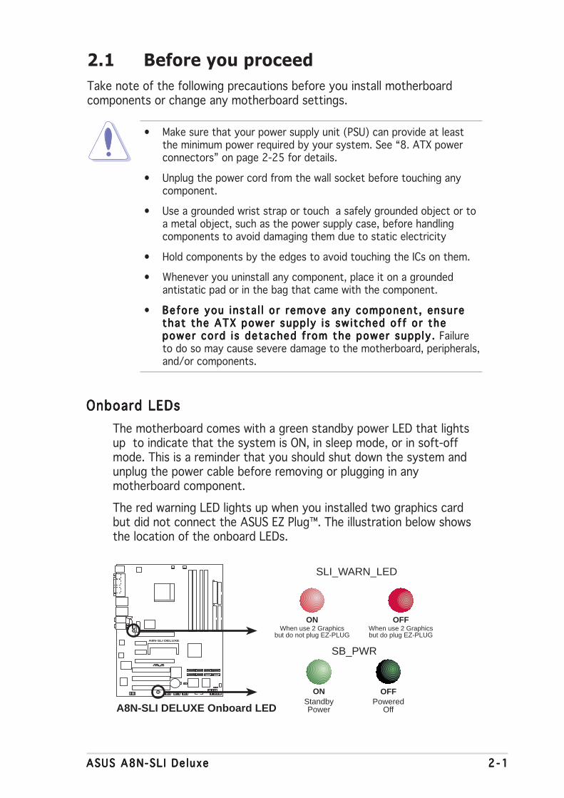
Onboard LEDsOnboard LEDsOnboard LEDsOnboard LEDsOnboard LEDs
The motherboard comes with a green standby power LED that lightsup to indicate that the system is ON, in sleep mode, or in soft-offmode. This is a reminder that you should shut down the system andunplug the power cable before removing or plugging in anymotherboard component.
The red warning LED lights up when you installed two graphics cardbut did not connect the ASUS EZ Plug™. The illustration below showsthe location of the onboard LEDs.
A8N-SLI DELUXE
®
A8N-SLI DELUXE Onboard LED
SB_PWR
ONStandbyPower
OFFPowered
Off
SLI_WARN_LED
When use 2 Graphicsbut do not plug EZ-PLUG
ON OFFWhen use 2 Graphicsbut do plug EZ-PLUG
2 - 22 - 22 - 22 - 22 - 2 Chapter 2 : Hardware in format ionChapter 2 : Hardware in format ionChapter 2 : Hardware in format ionChapter 2 : Hardware in format ionChapter 2 : Hardware in format ion
A8N-SLI DELUXE
2.2 Motherboard overview
Before you install the motherboard, study the configuration of your chassisto ensure that the motherboard fits into it.
Make sure to unplug the power cord before installing or removing themotherboard. Failure to do so can cause you physical injury and damagemotherboard components.
Do not overtighten the screws! Doing so can damage the motherboard.
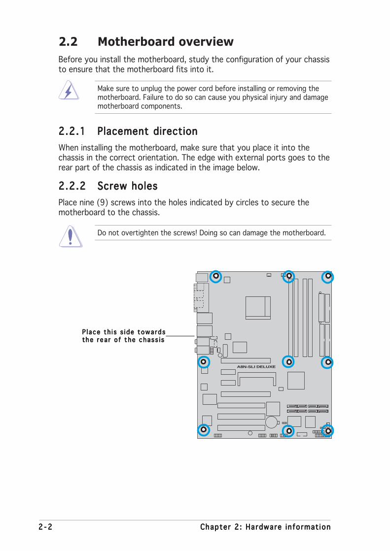
2.2.12.2.12.2.12.2.12.2.1 Placement directionPlacement directionPlacement directionPlacement directionPlacement direction
When installing the motherboard, make sure that you place it into thechassis in the correct orientation. The edge with external ports goes to therear part of the chassis as indicated in the image below.
2.2.22.2.22.2.22.2.22.2.2 Screw holesScrew holesScrew holesScrew holesScrew holes
Place nine (9) screws into the holes indicated by circles to secure themotherboard to the chassis.
P l ace th i s s i de towa rdsP l ace th i s s i de towa rdsP l ace th i s s i de towa rdsP l ace th i s s i de towa rdsP l ace th i s s i de towa rdsthe r ea r o f the chass i sthe r ea r o f the chass i sthe r ea r o f the chass i sthe r ea r o f the chass i sthe r ea r o f the chass i s
ASUS A8N-SL I De luxeASUS A8N-SL I De luxeASUS A8N-SL I De luxeASUS A8N-SL I De luxeASUS A8N-SL I De luxe 2 - 32 - 32 - 32 - 32 - 3
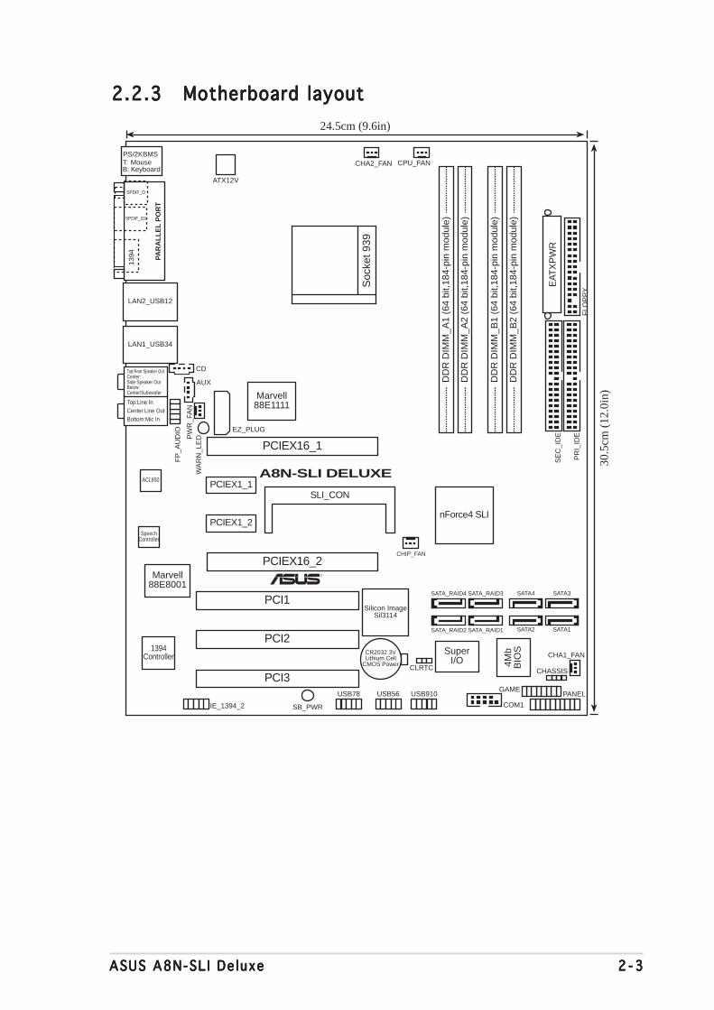
2.2.32.2.32.2.32.2.32.2.3 Motherboard layoutMotherboard layoutMotherboard layoutMotherboard layoutMotherboard layout
Bottom:Mic InCenter:Line OutTop:Line In
Below:Center/Subwoofer
Center:Side Speaker Out
Top:Rear Speaker Out
PANEL
A8N-SLI DELUXE
®
CR2032 3VLithium Cell
CMOS Power
AUX
FP
_AU
DIO
GAME
CHASSIS
PR
I_ID
E
SE
C_I
DE
EAT
XP
WR
Marvell88E8001
COM1
24.5cm (9.6in)
30.5
cm (
12.0
in)
CPU_FAN
Soc
ket 9
39
DD
R D
IMM
_B1
(64
bit,1
84-p
in m
odul
e)
DD
R D
IMM
_A1
(64
bit,1
84-p
in m
odul
e)
DD
R D
IMM
_A2
(64
bit,1
84-p
in m
odul
e)
DD
R D
IMM
_B2
(64
bit,1
84-p
in m
odul
e)
CHA2_FAN
LAN2_USB12
IE_1394_2
SATA_RAID3
PW
R_F
AN
FLO
PP
Y
SuperI/O
1394Controller
4Mb
BIO
S
Silicon ImageSil3114
PS/2KBMST: MouseB: Keyboard
PAR
AL
LE
L P
OR
T
SPDIF_O
SPDIF_O2
LAN1_USB34
CD
WA
RN
_LE
D
EZ_PLUG
SpeechController
ACL850
PCIEX16_1
PCIEX1_1
PCIEX1_2
PCIEX16_2
PCI1
PCI2
PCI3
Marvell88E1111
CLRTC
USB78 USB56 USB910
SATA1SATA2
SATA3SATA4SATA_RAID4
SATA_RAID1SATA_RAID2
CHA1_FAN
ATX12V
1394
SLI_CON
nForce4 SLI
CHIP_FAN
SB_PWR

2 - 42 - 42 - 42 - 42 - 4 Chapter 2 : Hardware in format ionChapter 2 : Hardware in format ionChapter 2 : Hardware in format ionChapter 2 : Hardware in format ionChapter 2 : Hardware in format ion
2.2.42.2.42.2.42.2.42.2.4 Layout ContentsLayout ContentsLayout ContentsLayout ContentsLayout Contents
S l o t sS l o t sS l o t sS l o t sS l o t s P a g eP a g eP a g eP a g eP a g e
1. DDR DIMM slots 2-11
2. PCI slots 2-16
3. PCI Express x16 slot 2-16
4. PCI Express x1 slot 2-16
Jumpe r sJ umpe r sJ umpe r sJ umpe r sJ umpe r s P a g eP a g eP a g eP a g eP a g e
1. Clear RTC RAM (3-pin CLRTC1) 2-17
Rea r pane l connec to r sRea r pane l connec to r sRea r pane l connec to r sRea r pane l connec to r sRea r pane l connec to r s P a g eP a g eP a g eP a g eP a g e
1. PS/2 mouse port (green) 2-18
2. Parallel port 2-18
3. LAN 2 (RJ-45) port 2-18
4. LAN 1 (RJ-45) port 2-18
5. Rear Speaker Out port (gray) 2-18
6. Side Speaker Out port (black) 2-18
7. Line In port (light blue) 2-18
8. Line Out port (lime) 2-18
9. Microphone port (pink) 2-17
10. Center/Subwoofer port (yellow orange) 2-17
11. USB 2.0 ports 3 and 4 2-17
12. USB 2.0 ports 1 and 2 2-17
13. IEEE 1394a port 2-17
14. Optical S/PDIF out port 2-17
15. Coaxial S/PDIF out port 2-17
16. PS/2 keyboard port (purple) 2-17

ASUS A8N-SL I De luxeASUS A8N-SL I De luxeASUS A8N-SL I De luxeASUS A8N-SL I De luxeASUS A8N-SL I De luxe 2 - 52 - 52 - 52 - 52 - 5
In te rna l connec to r sI n te rna l connec to r sI n te rna l connec to r sI n te rna l connec to r sI n te rna l connec to r s P a g eP a g eP a g eP a g eP a g e
1. Floppy disk drive connector (34-1 pin FLOPPY) 2-20
2. Primary IDE connector (40-1 pin PRI_IDE1) 2-20
3. Secondary IDE connector (40-1 pin SEC_IDE1) 2-20
4. Serial ATA connectors (7-pin SATA1, SATA2, SATA3, SATA4) [nForce4] 2-21
5. Serial ATA RAID connectors (7-pin SATA_RAID1, SATA_RAID2, SATA_RAID3, SATA_RAID4) [Silicon Image] 2-22
6. CPU fan connector (3-pin CPU_FAN) 2-23
7. Power fan connector (3-pin PWR_FAN) 2-23
8. Chassis fan 1 connector (3-pin CHA1_FAN) 2-23
9. Chassis fan 2 connector (3-pin CHA2_FAN) 2-23
10. Chipset fan connector (3-pin CHIP_FAN) 2-23
11. Serial port connector (10-1 pin COM1) 2-24
12. USB headers (10-1 USB56, USB78, USB910) 2-24
13. ATX power connector (24-pin EATXPWR1) 2-25
14. ATX 12V power connector (4-pin ATX12V1) 2-25
15. ATX 12V power connector (4-pin EZ_PLUG) 2-25
16. Optical audio connector (4-pin CD) 2-26
17. Auxiliary audio connector (4-pin AUX) 2-26
18. GAME/MIDI connector (16-1 pin GAME) 2-26
19. Chassis intrusion connector (4-1 pin CHASSIS) 2-27
20. IEEE 1394a connector (10-1 pin IE1394_1) 2-27
21. Front panel audio connector (10-1 pin FP_AUDIO) 2-28
22. ASUS EZ selector card connector (144-pin SLI_CON) 2-28
22. System panel connectors (20-1 pin PANEL) 2-29- System Power LED (Green 3-pin PLED)- Hard Disk activity (Red 2-pin IDE_LED)- System warning speaker (Orange 4-pin SPEAKER)- Power/Soft-off button(Yellow 2-pin PWRSW)- Reset switch (Blue 2-pin RESET)
2 - 62 - 62 - 62 - 62 - 6 Chapter 2 : Hardware in format ionChapter 2 : Hardware in format ionChapter 2 : Hardware in format ionChapter 2 : Hardware in format ionChapter 2 : Hardware in format ion
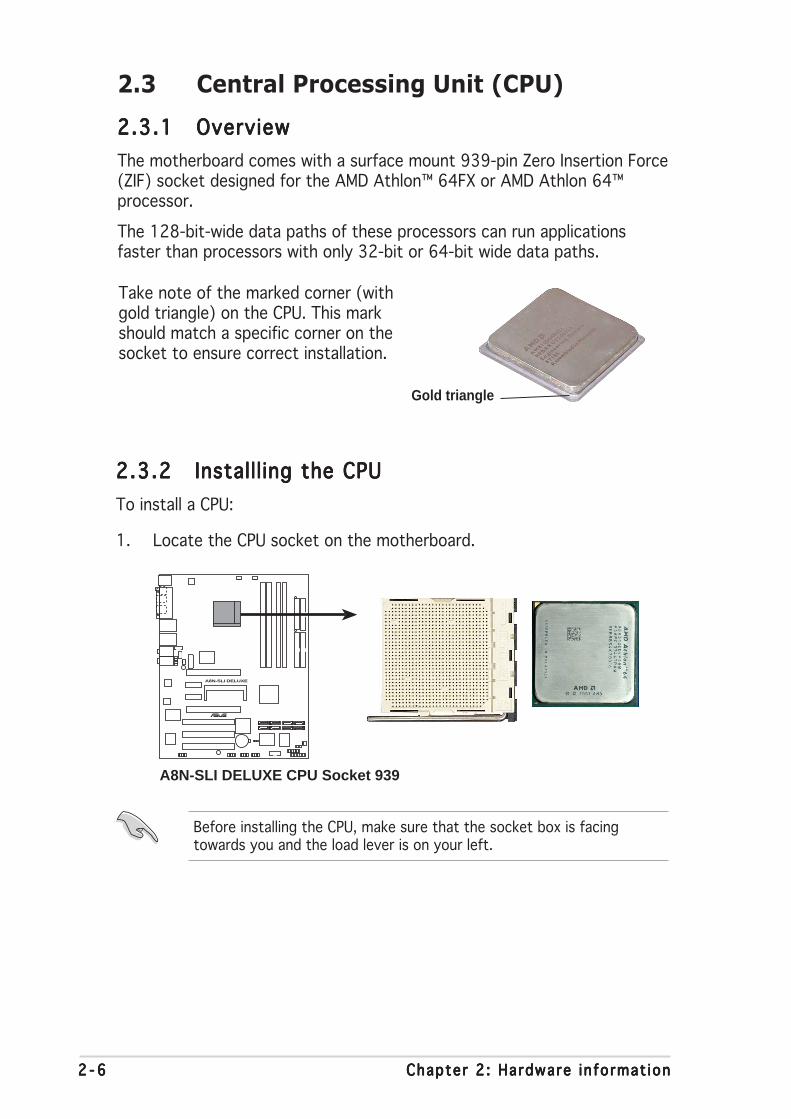
2.3.22.3.22.3.22.3.22.3.2 Installl ing the CPUInstalll ing the CPUInstalll ing the CPUInstalll ing the CPUInstalll ing the CPU
To install a CPU:
1. Locate the CPU socket on the motherboard.
2.3 Central Processing Unit (CPU)
2.3.12.3.12.3.12.3.12.3.1 OverviewOverviewOverviewOverviewOverview
The motherboard comes with a surface mount 939-pin Zero Insertion Force(ZIF) socket designed for the AMD Athlon™ 64FX or AMD Athlon 64™processor.
The 128-bit-wide data paths of these processors can run applicationsfaster than processors with only 32-bit or 64-bit wide data paths.
Before installing the CPU, make sure that the socket box is facingtowards you and the load lever is on your left.
Take note of the marked corner (withgold triangle) on the CPU. This markshould match a specific corner on thesocket to ensure correct installation.
Gold triangle
A8N-SLI DELUXE
®
A8N-SLI DELUXE CPU Socket 939
ASUS A8N-SL I De luxeASUS A8N-SL I De luxeASUS A8N-SL I De luxeASUS A8N-SL I De luxeASUS A8N-SL I De luxe 2 - 72 - 72 - 72 - 72 - 7
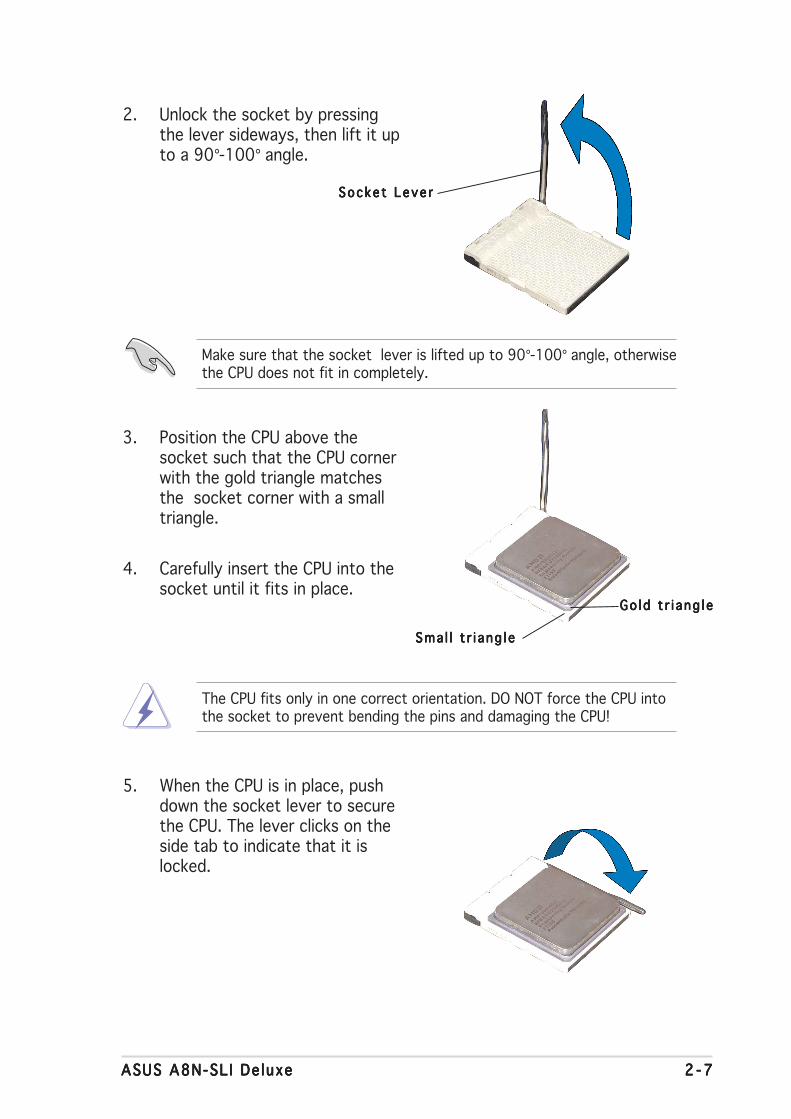
3. Position the CPU above thesocket such that the CPU cornerwith the gold triangle matchesthe socket corner with a smalltriangle.
4. Carefully insert the CPU into thesocket until it fits in place.
2. Unlock the socket by pressingthe lever sideways, then lift it upto a 90°-100° angle.
Make sure that the socket lever is lifted up to 90°-100° angle, otherwisethe CPU does not fit in completely.
The CPU fits only in one correct orientation. DO NOT force the CPU intothe socket to prevent bending the pins and damaging the CPU!
5. When the CPU is in place, pushdown the socket lever to securethe CPU. The lever clicks on theside tab to indicate that it islocked.
Go l d t r i a ng l eGo l d t r i a ng l eGo l d t r i a ng l eGo l d t r i a ng l eGo l d t r i a ng l e
Sma l l t r i a ng l eSma l l t r i a ng l eSma l l t r i a ng l eSma l l t r i a ng l eSma l l t r i a ng l e
Socke t Leve rSocke t Leve rSocke t Leve rSocke t Leve rSocke t Leve r
2 - 82 - 82 - 82 - 82 - 8 Chapter 2 : Hardware in format ionChapter 2 : Hardware in format ionChapter 2 : Hardware in format ionChapter 2 : Hardware in format ionChapter 2 : Hardware in format ion
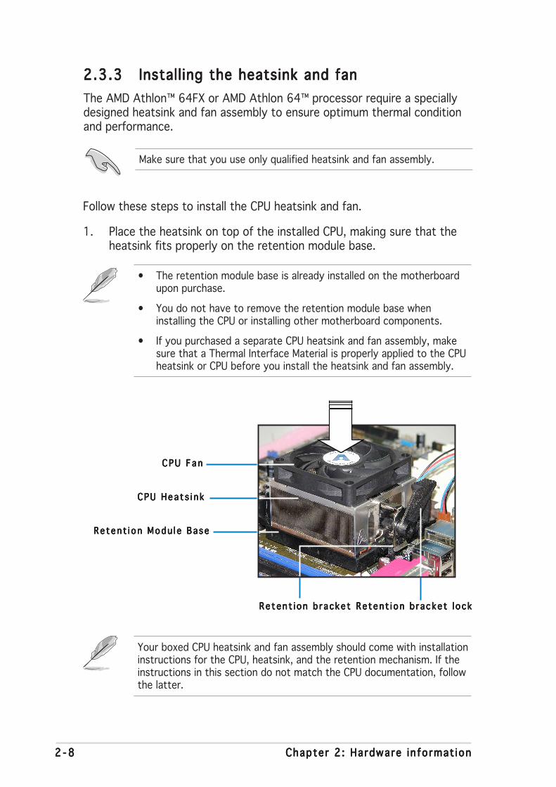
2.3.32.3.32.3.32.3.32.3.3 Installing the heatsink and fanInstalling the heatsink and fanInstalling the heatsink and fanInstalling the heatsink and fanInstalling the heatsink and fan
The AMD Athlon™ 64FX or AMD Athlon 64™ processor require a speciallydesigned heatsink and fan assembly to ensure optimum thermal conditionand performance.
Follow these steps to install the CPU heatsink and fan.
1. Place the heatsink on top of the installed CPU, making sure that theheatsink fits properly on the retention module base.
Retent i on Modu l e BaseRetent i on Modu l e BaseRetent i on Modu l e BaseRetent i on Modu l e BaseRetent i on Modu l e Base
CPU Hea t s i n kCPU Hea t s i n kCPU Hea t s i n kCPU Hea t s i n kCPU Hea t s i n k
CPU F anCPU F anCPU F anCPU F anCPU F an
Retent i on b racke t l ockRetent i on b racke t l ockRetent i on b racke t l ockRetent i on b racke t l ockRetent i on b racke t l ockReten t i on b r acke tRe ten t i on b r acke tRe ten t i on b r acke tRe ten t i on b r acke tRe ten t i on b r acke t
Make sure that you use only qualified heatsink and fan assembly.
• The retention module base is already installed on the motherboardupon purchase.
• You do not have to remove the retention module base wheninstalling the CPU or installing other motherboard components.
• If you purchased a separate CPU heatsink and fan assembly, makesure that a Thermal Interface Material is properly applied to the CPUheatsink or CPU before you install the heatsink and fan assembly.
Your boxed CPU heatsink and fan assembly should come with installationinstructions for the CPU, heatsink, and the retention mechanism. If theinstructions in this section do not match the CPU documentation, followthe latter.
ASUS A8N-SL I De luxeASUS A8N-SL I De luxeASUS A8N-SL I De luxeASUS A8N-SL I De luxeASUS A8N-SL I De luxe 2 - 92 - 92 - 92 - 92 - 9
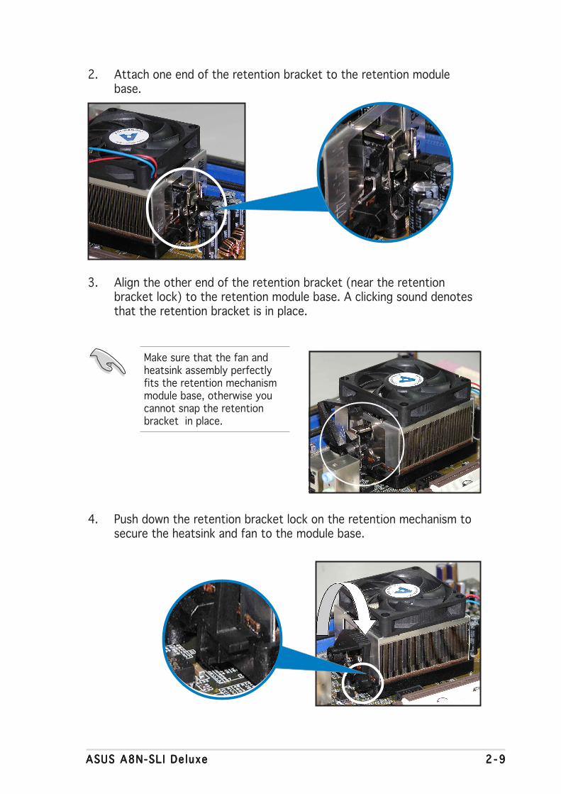
2. Attach one end of the retention bracket to the retention modulebase.
3. Align the other end of the retention bracket (near the retentionbracket lock) to the retention module base. A clicking sound denotesthat the retention bracket is in place.
4. Push down the retention bracket lock on the retention mechanism tosecure the heatsink and fan to the module base.
Make sure that the fan andheatsink assembly perfectlyfits the retention mechanismmodule base, otherwise youcannot snap the retentionbracket in place.

2 -102 -102 -102 -102 -10 Chapter 2 : Hardware in format ionChapter 2 : Hardware in format ionChapter 2 : Hardware in format ionChapter 2 : Hardware in format ionChapter 2 : Hardware in format ion
3. When the fan and heatsink assembly is in place, connect the CPU fancable to the connector on the motherboard labeled CPU_FAN.
Do not forget to connect the CPU fan connector! Hardware monitoringerrors can occur if you fail to plug this connector.
A8N-SLI DELUXE
®
A8N-SLI DELUXE CPU fan connector
CPU_FAN
GN
D
Rot
atio
n+
12V

ASUS A8N-SL I De luxeASUS A8N-SL I De luxeASUS A8N-SL I De luxeASUS A8N-SL I De luxeASUS A8N-SL I De luxe 2 -112 -112 -112 -112 -11
2.4 System memory
2.4.12.4.12.4.12.4.12.4.1 OverviewOverviewOverviewOverviewOverview
The motherboard comes with four 184-pin Double Data Rate (DDR) DualInline Memory Modules (DIMM) sockets.
The following figure illustrates the location of the sockets:
2.4.22.4.22.4.22.4.22.4.2 Memory ConfigurationsMemory ConfigurationsMemory ConfigurationsMemory ConfigurationsMemory Configurations
You may install 256 MB, 512 MB and 1 GB unbuffered ECC or non-ECC DDRDIMMs into the DIMM sockets using the memory configurations in thissection.
• For dual-channel configuration, the total size of memory module(s)installed per channel must be the same for better performance(DIMM_A1+DIMM_A2=DIMM_B1+DIMM_B2).
• When using one DDR DIMM module, install into DIMM_B1 slot only.
• When using two DDR DIMM modules, install into DIMM_A1 andDIMM_B1 slots only.
• Always install DIMMs with the same CAS latency. For optimumcompatibility, it is recommended that you obtain memory modulesfrom the same vendor. Refer to the DDR400 Qualified Vendors Liston the next page for details.
• Due to chipset resource allocation, the system may detect less than4 GB of system memory when you installed four 1 GB DDR memorymodules.
• Due to CPU limitation, DIMM modules with 128 Mb memory chips ordouble-sided x16 memory chips are not supported in thismotherboard.
Channe lChanne lChanne lChanne lChanne l Sockets Sockets Sockets Sockets Sockets
Channel A DIMM_A1 and DIMM_A2
Channel B DIMM_B1 and DIMM_B2
A8N-SLI DELUXE
®
A8N-SLI DELUXE 184-pin DDR DIMM socketsD
IMM
_A1
DIM
M_A
2
DIM
M_B
1
DIM
M_B
2

2 -122 -122 -122 -122 -12 Chapter 2 : Hardware in format ionChapter 2 : Hardware in format ionChapter 2 : Hardware in format ionChapter 2 : Hardware in format ionChapter 2 : Hardware in format ion
Visit the ASUS website (www.asus.com) for the latest DDR 400 QualifiedVendors List.
DDR400 Qualified Vendors ListDDR400 Qualified Vendors ListDDR400 Qualified Vendors ListDDR400 Qualified Vendors ListDDR400 Qualified Vendors List
S ide(s) : SS - S ide(s) : SS - S ide(s) : SS - S ide(s) : SS - S ide(s) : SS - Single-Sided D S -D S -D S -D S -D S - Double-Sided
D IMM Support :D IMM Support :D IMM Support :D IMM Support :D IMM Support :
AAAAA - supports one module inserted into either the blue slots, in a Single-channelmemory configuration.
BBBBB - supports on pair of modules inserted into either the blue slots or the black slotsas one pair of Dual-channel memory configuration.
CCCCC - support for 4 modules inserted into the blue and black slots as two pairs ofDual-channel memory configuration.
D I M M s u p p o r tD I M M s u p p o r tD I M M s u p p o r tD I M M s u p p o r tD I M M s u p p o r t
S i z eS i z eS i z eS i z eS i z e V e n d o rV e n d o rV e n d o rV e n d o rV e n d o r M o d e l M o d e l M o d e l M o d e l M o d e l B r a n d S i d e ( s ) B r a n d S i d e ( s ) B r a n d S i d e ( s ) B r a n d S i d e ( s ) B r a n d S i d e ( s ) C o m p o n e n t C o m p o n e n t C o m p o n e n t C o m p o n e n t C o m p o n e n t AAAAA BBBBB CCCCC
256MB KINGSTON KVR400X64C3A/256 Hynix SS HY5DU56822BT-D43 • • •
512MB KINGSTON KVR400X64C3A/512 Hynix DS HY5DU56822BT-D43 • • •
256MB KINGSTON KVR400X72C3A/256 Mosel SS V58C2256804SAT5(ECC) • • •
512MB KINGSTON KVR400X72C3A/512 Mosel DS V58C2256804SAT5(ECC) • •
256MB KINGSTON KVR400X64C3A/256 Infineon SS HYB25D256800BT-5B • • •
512MB KINGSTON KVR400X64C3A/512 Infineon DS HYB25D256809BT-5B • •
256MB KINGSTON KVR400X64C3A/256 KINGSTON SS D3208DL2T-5 • • •
512MB KINGSTON KVR400X64C3A/512 KINGSTON DS D328DIB-50 • • •
1024MB KINGSTON HYB25D512800BE-5B N/A DS KVR400X64C3A/1G • • •
256MB SAMSUNG M381L3223ETM-CCC SAMSUNG SS K4H560838E-TCCC(ECC) • • •
512MB SAMSUNG M381L6423ETM-CCC SAMSUNG DS K4H560838E-TCCC(ECC) •
256MB SAMSUNG M368L3223ETM-CCC SAMSUNG SS K4H560838E-TCCC • • •
256MB SAMSUNG M368L3223FTN-CCC SAMSUNG SS K4H560838F-TCCC • • •
512MB SAMSUNG M368L6423FTN-CCC SAMSUNG DS K4H560838F-TCCC • • •
512MB SAMSUNG M368L6523BTM-CCC SAMSUNG SS K4H510838B-TCCC • • •
256MB MICRON MT8VDDT3264AG-40BCB MICRON SS MT46V32M8TG-5BC • • •
512MB MICRON MT16VDDT6464AG-40BCB MICRON DS MT46V32M8TG-5BC • • •
256MB Infineon HYS64D32300HU-5-C Infineon SS HYB25D256800CE-5C • • •
512MB Infineon HYS64D64320HU-5-C Infineon DS HYB25D256800CE-5C • • •
256MB CORSAIR CMX256A-3200C2PT Winbond SS W942508BH-5 • • •
512MB CORSAIR VS512MB400 VALUE seLecT DS VS32M8-5 • •
1024MB CORSAIR TWINX2048-3200C2 N/A DS N/A • •
256MB Hynix HYMD232645D8J-D43 Hynix SS HY5DU56822DT-D43 • • •
512MB Hynix HYMD264646D8J-D43 Hynix DS HY5DU56822DT-D43 • • •
ASUS A8N-SL I De luxeASUS A8N-SL I De luxeASUS A8N-SL I De luxeASUS A8N-SL I De luxeASUS A8N-SL I De luxe 2 -132 -132 -132 -132 -13
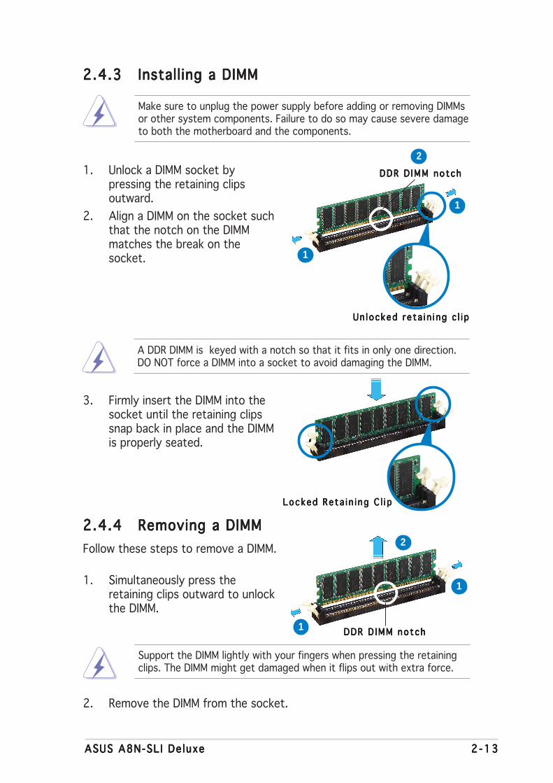
2.4.42.4.42.4.42.4.42.4.4 Removing a DIMMRemoving a DIMMRemoving a DIMMRemoving a DIMMRemoving a DIMM
Follow these steps to remove a DIMM.
1. Simultaneously press theretaining clips outward to unlockthe DIMM.
2. Remove the DIMM from the socket.
Support the DIMM lightly with your fingers when pressing the retainingclips. The DIMM might get damaged when it flips out with extra force.
2.4.32.4.32.4.32.4.32.4.3 Installing a DIMMInstalling a DIMMInstalling a DIMMInstalling a DIMMInstalling a DIMM
3. Firmly insert the DIMM into thesocket until the retaining clipssnap back in place and the DIMMis properly seated.
1. Unlock a DIMM socket bypressing the retaining clipsoutward.
2. Align a DIMM on the socket suchthat the notch on the DIMMmatches the break on thesocket.
Locked Re ta i n i ng C l i pLocked Re ta i n i ng C l i pLocked Re ta i n i ng C l i pLocked Re ta i n i ng C l i pLocked Re ta i n i ng C l i p
Make sure to unplug the power supply before adding or removing DIMMsor other system components. Failure to do so may cause severe damageto both the motherboard and the components.
A DDR DIMM is keyed with a notch so that it fits in only one direction.DO NOT force a DIMM into a socket to avoid damaging the DIMM.
Un locked re ta i n i ng c l i pUn locked re ta i n i ng c l i pUn locked re ta i n i ng c l i pUn locked re ta i n i ng c l i pUn locked re ta i n i ng c l i p
DDR D IMM no tchDDR D IMM no tchDDR D IMM no tchDDR D IMM no tchDDR D IMM no tch
1
2
1
DDR D IMM no tchDDR D IMM no tchDDR D IMM no tchDDR D IMM no tchDDR D IMM no tch1
2
1

2 -142 -142 -142 -142 -14 Chapter 2 : Hardware in format ionChapter 2 : Hardware in format ionChapter 2 : Hardware in format ionChapter 2 : Hardware in format ionChapter 2 : Hardware in format ion
2.5 Expansion slots
In the future, you may need to install expansion cards. The followingsub-sections describe the slots and the expansion cards that they support.
2.5.12.5.12.5.12.5.12.5.1 Installing an expansion cardInstalling an expansion cardInstalling an expansion cardInstalling an expansion cardInstalling an expansion card
To install an expansion card:
1. Before installing the expansion card, read the documentation thatcame with it and make the necessary hardware settings for the card.
2. Remove the system unit cover (if your motherboard is alreadyinstalled in a chassis).
3. Remove the bracket opposite the slot that you intend to use. Keepthe screw for later use.
4. Align the card connector with the slot and press firmly until the card iscompletely seated on the slot.
5. Secure the card to the chassis with the screw you removed earlier.
6. Replace the system cover.
2.5.22.5.22.5.22.5.22.5.2 Configuring an expansion cardConfiguring an expansion cardConfiguring an expansion cardConfiguring an expansion cardConfiguring an expansion card
After installing the expansion card, configure the it by adjusting thesoftware settings.
1. Turn on the system and change the necessary BIOS settings, if any.See Chapter 4 for information on BIOS setup.
2. Assign an IRQ to the card. Refer to the tables on the next page.
3. Install the software drivers for the expansion card.
Make sure to unplug the power cord before adding or removingexpansion cards. Failure to do so may cause you physical injury anddamage motherboard components.
ASUS A8N-SL I De luxeASUS A8N-SL I De luxeASUS A8N-SL I De luxeASUS A8N-SL I De luxeASUS A8N-SL I De luxe 2 -152 -152 -152 -152 -15
2.5.32.5.32.5.32.5.32.5.3 Interrupt assignmentsInterrupt assignmentsInterrupt assignmentsInterrupt assignmentsInterrupt assignments
Standard interrupt assignmentsStandard interrupt assignmentsStandard interrupt assignmentsStandard interrupt assignmentsStandard interrupt assignments
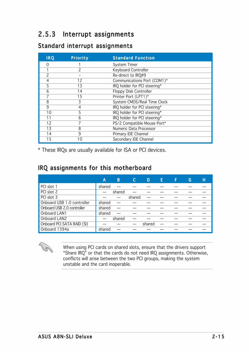
I R QI R QI R QI R QI R Q P r i o r i t yP r i o r i t yP r i o r i t yP r i o r i t yP r i o r i t y S tanda rd Func t i onStanda rd Func t i onStanda rd Func t i onStanda rd Func t i onStanda rd Func t i on
0 1 System Timer1 2 Keyboard Controller2 – Re-direct to IRQ#94 12 Communications Port (COM1)*5 13 IRQ holder for PCI steering*6 14 Floppy Disk Controller7 15 Printer Port (LPT1)*8 3 System CMOS/Real Time Clock9 4 IRQ holder for PCI steering*10 5 IRQ holder for PCI steering*11 6 IRQ holder for PCI steering*12 7 PS/2 Compatible Mouse Port*13 8 Numeric Data Processor14 9 Primary IDE Channel15 10 Secondary IDE Channel
* These IRQs are usually available for ISA or PCI devices.
IRQ assignments for this motherboardIRQ assignments for this motherboardIRQ assignments for this motherboardIRQ assignments for this motherboardIRQ assignments for this motherboard
AAAAA BBBBB CCCCC DDDDD EEEEE FFFFF GGGGG HHHHH
PCI slot 1 shared — — — — — — —PCI slot 2 — shared — — — — — —PCI slot 3 — — shared — — — — —Onboard USB 1.0 controller shared — — — — — — —Onboard USB 2.0 controller shared — — — — — — —Onboard LAN1 shared — — — — — — —Onboard LAN2 — shared — — — — — —Onboard PCI SATA RAID (SI) — — — shared — — — —Onboard 1394a shared — — — — — — —
When using PCI cards on shared slots, ensure that the drivers support“Share IRQ” or that the cards do not need IRQ assignments. Otherwise,conflicts will arise between the two PCI groups, making the systemunstable and the card inoperable.
2 -162 -162 -162 -162 -16 Chapter 2 : Hardware in format ionChapter 2 : Hardware in format ionChapter 2 : Hardware in format ionChapter 2 : Hardware in format ionChapter 2 : Hardware in format ion
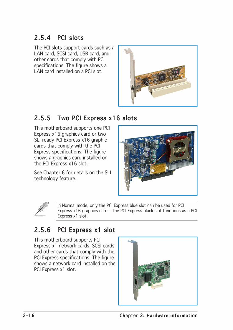
2.5.42.5.42.5.42.5.42.5.4 PCI slotsPCI slotsPCI slotsPCI slotsPCI slots
The PCI slots support cards such as aLAN card, SCSI card, USB card, andother cards that comply with PCIspecifications. The figure shows aLAN card installed on a PCI slot.
2.5.52.5.52.5.52.5.52.5.5 Two PCI Express x16 slotsTwo PCI Express x16 slotsTwo PCI Express x16 slotsTwo PCI Express x16 slotsTwo PCI Express x16 slots
This motherboard supports one PCIExpress x16 graphics card or twoSLI-ready PCI Express x16 graphiccards that comply with the PCIExpress specifications. The figureshows a graphics card installed onthe PCI Express x16 slot.
See Chapter 6 for details on the SLItechnology feature.
2.5.62.5.62.5.62.5.62.5.6 PCI Express x1 slotPCI Express x1 slotPCI Express x1 slotPCI Express x1 slotPCI Express x1 slot
This motherboard supports PCIExpress x1 network cards, SCSI cardsand other cards that comply with thePCI Express specifications. The figureshows a network card installed on thePCI Express x1 slot.
In Normal mode, only the PCI Express blue slot can be used for PCIExpress x16 graphics cards. The PCI Express black slot functions as a PCIExpress x1 slot.
ASUS A8N-SL I De luxeASUS A8N-SL I De luxeASUS A8N-SL I De luxeASUS A8N-SL I De luxeASUS A8N-SL I De luxe 2 -172 -172 -172 -172 -17
2.6 Jumpers
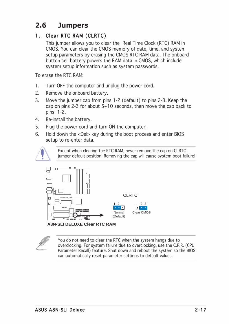
1 .1 .1 .1 .1 . C lear RTC RAM (CLRTC)Clear RTC RAM (CLRTC)Clear RTC RAM (CLRTC)Clear RTC RAM (CLRTC)Clear RTC RAM (CLRTC)
This jumper allows you to clear the Real Time Clock (RTC) RAM inCMOS. You can clear the CMOS memory of date, time, and systemsetup parameters by erasing the CMOS RTC RAM data. The onboardbutton cell battery powers the RAM data in CMOS, which includesystem setup information such as system passwords.
To erase the RTC RAM:
1. Turn OFF the computer and unplug the power cord.
2. Remove the onboard battery.
3. Move the jumper cap from pins 1-2 (default) to pins 2-3. Keep thecap on pins 2-3 for about 5~10 seconds, then move the cap back topins 1-2.
4. Re-install the battery.
5. Plug the power cord and turn ON the computer.
6. Hold down the <Del> key during the boot process and enter BIOSsetup to re-enter data.
Except when clearing the RTC RAM, never remove the cap on CLRTCjumper default position. Removing the cap will cause system boot failure!
You do not need to clear the RTC when the system hangs due tooverclocking. For system failure due to overclocking, use the C.P.R. (CPUParameter Recall) feature. Shut down and reboot the system so the BIOScan automatically reset parameter settings to default values.
A8N-SLI DELUXE
®
A8N-SLI DELUXE Clear RTC RAM
CLRTC
Normal Clear CMOS(Default)
1 2 2 3

2 -182 -182 -182 -182 -18 Chapter 2 : Hardware in format ionChapter 2 : Hardware in format ionChapter 2 : Hardware in format ionChapter 2 : Hardware in format ionChapter 2 : Hardware in format ion
2.7 Connectors
2.7.12.7.12.7.12.7.12.7.1 Rear panel connectorsRear panel connectorsRear panel connectorsRear panel connectorsRear panel connectors
1 .1 .1 .1 .1 . PS/2 mouse port (green).PS/2 mouse port (green).PS/2 mouse port (green).PS/2 mouse port (green).PS/2 mouse port (green). This port is for a PS/2 mouse.
2 .2 .2 .2 .2 . Para l le l port .Para l le l port .Para l le l port .Para l le l port .Para l le l port . This 25-pin port connects a parallel printer, a scanner,or other devices.
3 .3 .3 .3 .3 . LAN 2 (RJ-45) port .LAN 2 (RJ-45) port .LAN 2 (RJ-45) port .LAN 2 (RJ-45) port .LAN 2 (RJ-45) port . Supported by the Marvell® 88E81001 GigabitLAN controller, this port allows Gigabit connection to a Local AreaNetwork (LAN) through a network hub.
4 .4 .4 .4 .4 . LAN 1 (RJ-45) port .LAN 1 (RJ-45) port .LAN 1 (RJ-45) port .LAN 1 (RJ-45) port .LAN 1 (RJ-45) port . Supported by the NVIDIA® nForce™ 4 GigabitMAC with external Marvell® PHY, this port allows Gigabit connection toa Local Area Network (LAN) through a network hub. Refer to the tablebelow for the LAN port LED indications.
SPEEDLED
ACT/LINKLED
LAN port
LAN port LED indicationsLAN port LED indicationsLAN port LED indicationsLAN port LED indicationsLAN port LED indications
5 .5 .5 .5 .5 . Rear Speaker Out port (gray).Rear Speaker Out port (gray).Rear Speaker Out port (gray).Rear Speaker Out port (gray).Rear Speaker Out port (gray). This port connects the rearspeakers on a 4-channel, 6-channel, or 8-channel audio configuration.
6 .6 .6 .6 .6 . S ide Speaker Out port (b lack).S ide Speaker Out port (b lack).S ide Speaker Out port (b lack).S ide Speaker Out port (b lack).S ide Speaker Out port (b lack). This port connects the sidespeakers in an 8-channel audio configuration.
7 .7 .7 .7 .7 . L ine In port ( l ight b lue).L ine In port ( l ight b lue).L ine In port ( l ight b lue).L ine In port ( l ight b lue).L ine In port ( l ight b lue). This port connects the tape, CD, DVDplayer, or other audio sources.
8 .8 .8 .8 .8 . L ine Out port ( l ime).L ine Out port ( l ime).L ine Out port ( l ime).L ine Out port ( l ime).L ine Out port ( l ime). This port connects a headphone or aspeaker. In 4-channel, 6-channel, and 8-channel configuration, thefunction of this port becomes Front Speaker Out.
ACT/L INK LED ACT/L INK LED ACT/L INK LED ACT/L INK LED ACT/L INK LED SPEED LED SPEED LED SPEED LED SPEED LED SPEED LED
S t a t u sS t a t u sS t a t u sS t a t u sS t a t u s Desc r i p t i onDesc r i p t i onDesc r i p t i onDesc r i p t i onDesc r i p t i on S t a t u sS t a t u sS t a t u sS t a t u sS t a t u s Desc r i p t i onDesc r i p t i onDesc r i p t i onDesc r i p t i onDesc r i p t i on
OFF No link OFF 10 Mbps connection
GREEN Linked ORANGE 100 Mbps connection
BLINKING Data activity GREEN 1 Gbps connection
11
4 5
10
6
7
8
9
13
1
16
2
15 14 12
3

ASUS A8N-SL I De luxeASUS A8N-SL I De luxeASUS A8N-SL I De luxeASUS A8N-SL I De luxeASUS A8N-SL I De luxe 2 -192 -192 -192 -192 -19
11 .11 .11 .11 .11 . USB 2.0 ports 3 and 4.USB 2.0 ports 3 and 4.USB 2.0 ports 3 and 4.USB 2.0 ports 3 and 4.USB 2.0 ports 3 and 4. These two 4-pin Universal Serial Bus(USB) ports are available for connecting USB 2.0 devices.
12 .12 .12 .12 .12 . USB 2.0 ports 1 and 2.USB 2.0 ports 1 and 2.USB 2.0 ports 1 and 2.USB 2.0 ports 1 and 2.USB 2.0 ports 1 and 2. These two 4-pin Universal Serial Bus(USB) ports are available for connecting USB 2.0 devices.
13 .13 .13 .13 .13 . IEEE 1394a port .IEEE 1394a port .IEEE 1394a port .IEEE 1394a port .IEEE 1394a port . This 6-pin IEEE 1394 port provides high-speedconnectivity for audio/video devices, storage peripherals, PCs, orportable devices.
14 .14 .14 .14 .14 . Opt ica l S/PDIF Out portOpt ica l S/PDIF Out portOpt ica l S/PDIF Out portOpt ica l S/PDIF Out portOpt ica l S/PDIF Out port. This port connects an external audiooutput device via an optical S/PDIF cable.
15 .15 .15 .15 .15 . Coaxia l S/PDIF Out port .Coaxia l S/PDIF Out port .Coaxia l S/PDIF Out port .Coaxia l S/PDIF Out port .Coaxia l S/PDIF Out port . This port connects an external audiooutput device via a coaxial S/PDIF cable.
16 .16 .16 .16 .16 . PS/2 keyboard port (purple) .PS/2 keyboard port (purple) .PS/2 keyboard port (purple) .PS/2 keyboard port (purple) .PS/2 keyboard port (purple) . This port is for a PS/2 keyboard.
9 .9 .9 .9 .9 . Microphone port (p ink). Microphone port (p ink). Microphone port (p ink). Microphone port (p ink). Microphone port (p ink). This port connects a microphone.
10 .10 .10 .10 .10 . Center/Subwoofer port (yel low orange).Center/Subwoofer port (yel low orange).Center/Subwoofer port (yel low orange).Center/Subwoofer port (yel low orange).Center/Subwoofer port (yel low orange). This port connectsthe center/subwoofer speakers.
Audio 2, 4, 6, or 8-channel configurationAudio 2, 4, 6, or 8-channel configurationAudio 2, 4, 6, or 8-channel configurationAudio 2, 4, 6, or 8-channel configurationAudio 2, 4, 6, or 8-channel configuration
Light Blue Line In Line In Line In Line In
Lime Line Out Front Speaker Out Front Speaker Out Front Speaker Out
Pink Mic In Mic In Mic In Mic In
Gray • Rear Speaker Out Rear Speaker Out Rear Speaker Out
Black • • • Side Speaker Out
Yellow Orange • • Center/Subwoofer Center/Subwoofer
P o r tP o r tP o r tP o r tP o r t H e a d s e tH e a d s e tH e a d s e tH e a d s e tH e a d s e t 4 - channe l4 - channe l4 - channe l4 - channe l4 - channe l 6 - channe l6 - channe l6 - channe l6 - channe l6 - channe l 8 - channe l8 - channe l8 - channe l8 - channe l8 - channe l2-channel2-channel2-channel2-channel2-channel
Refer to the audio configuration table below for the function of theaudio ports in 2, 4, 6, or 8-channel configuration.
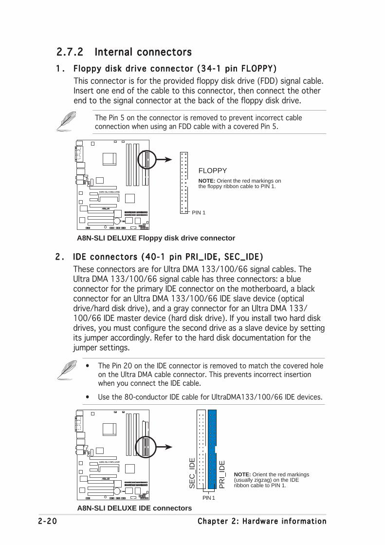
2 -202 -202 -202 -202 -20 Chapter 2 : Hardware in format ionChapter 2 : Hardware in format ionChapter 2 : Hardware in format ionChapter 2 : Hardware in format ionChapter 2 : Hardware in format ion
2 .2 .2 .2 .2 . IDE connectors (40-1 pin PRI_IDE, SEC_IDE)IDE connectors (40-1 pin PRI_IDE, SEC_IDE)IDE connectors (40-1 pin PRI_IDE, SEC_IDE)IDE connectors (40-1 pin PRI_IDE, SEC_IDE)IDE connectors (40-1 pin PRI_IDE, SEC_IDE)
These connectors are for Ultra DMA 133/100/66 signal cables. TheUltra DMA 133/100/66 signal cable has three connectors: a blueconnector for the primary IDE connector on the motherboard, a blackconnector for an Ultra DMA 133/100/66 IDE slave device (opticaldrive/hard disk drive), and a gray connector for an Ultra DMA 133/100/66 IDE master device (hard disk drive). If you install two hard diskdrives, you must configure the second drive as a slave device by settingits jumper accordingly. Refer to the hard disk documentation for thejumper settings.
2.7.22.7.22.7.22.7.22.7.2 Internal connectorsInternal connectorsInternal connectorsInternal connectorsInternal connectors
1 .1 .1 .1 .1 . F loppy disk dr ive connector (34-1 pin FLOPPY)Floppy disk dr ive connector (34-1 pin FLOPPY)Floppy disk dr ive connector (34-1 pin FLOPPY)Floppy disk dr ive connector (34-1 pin FLOPPY)Floppy disk dr ive connector (34-1 pin FLOPPY)
This connector is for the provided floppy disk drive (FDD) signal cable.Insert one end of the cable to this connector, then connect the otherend to the signal connector at the back of the floppy disk drive.
The Pin 5 on the connector is removed to prevent incorrect cableconnection when using an FDD cable with a covered Pin 5.
• The Pin 20 on the IDE connector is removed to match the covered holeon the Ultra DMA cable connector. This prevents incorrect insertionwhen you connect the IDE cable.
• Use the 80-conductor IDE cable for UltraDMA133/100/66 IDE devices.
A8N-SLI DELUXE
®
A8N-SLI DELUXE Floppy disk drive connector
NOTE: Orient the red markings onthe floppy ribbon cable to PIN 1.
PIN 1
FLOPPY
A8N-SLI DELUXE
®
A8N-SLI DELUXE IDE connectors
NOTE: Orient the red markings(usually zigzag) on the IDEribbon cable to PIN 1.P
RI_
IDE
PIN 1
SE
C_I
DE

ASUS A8N-SL I De luxeASUS A8N-SL I De luxeASUS A8N-SL I De luxeASUS A8N-SL I De luxeASUS A8N-SL I De luxe 2 -212 -212 -212 -212 -21
3 .3 .3 .3 .3 . Ser ia l ATA connectorsSer ia l ATA connectorsSer ia l ATA connectorsSer ia l ATA connectorsSer ia l ATA connectors(7-pin SATA1, SATA2, SATA3, SATA4)(7-pin SATA1, SATA2, SATA3, SATA4)(7-pin SATA1, SATA2, SATA3, SATA4)(7-pin SATA1, SATA2, SATA3, SATA4)(7-pin SATA1, SATA2, SATA3, SATA4)
Supported by the NVIDIA® nForce4™ chipset, these connectors are forthe Serial ATA signal cables for Serial ATA hard disk drives that allowsup to 3Gb/s of data transfer rate.
If you installed Serial ATA hard disk drives, you can create a RAID 0,RAID 1, RAID 1+0, or JBOD configuration that span across the ParallelATA drives. Refer to Chapter 5 for details on how to set up RAIDconfigurations.
Important notes on Ser ia l ATAImportant notes on Ser ia l ATAImportant notes on Ser ia l ATAImportant notes on Ser ia l ATAImportant notes on Ser ia l ATA
• The actual data transfer rate depends on the speed of Serial ATAhard disks installed.
• See Appendix for instructions on how to install the Serial ATAextension module.
A8N-SLI DELUXE
®
A8N-SLI DELUXE SATA connectors
SATA1SATA2
GN
DR
SAT
A_T
XP
4R
SAT
A_T
XN
4G
ND
RS
ATA
_RX
P4
RS
ATA
_RX
N4
GN
D
GN
DR
SAT
A_T
XP
3R
SAT
A_T
XN
3G
ND
RS
ATA
_RX
P3
RS
ATA
_RX
N3
GN
D
GN
DR
SAT
A_T
XP
2R
SAT
A_T
XN
2G
ND
RS
ATA
_RX
P2
RS
ATA
_RX
N2
GN
D
GN
DR
SAT
A_T
XP
1R
SAT
A_T
XN
1G
ND
RS
ATA
_RX
P1
RS
ATA
_RX
N1
GN
D
SATA3SATA4
These connectors are set to SATA SATA SATA SATA SATA by default. In SATA mode, you canconnect Serial ATA boot or data hard disk drives to these connectors. Ifyou intent to create a Serial ATA RAID set using these connectors,enable the RAID function of each port from the NVRA IDNVRA IDNVRA IDNVRA IDNVRA IDConf igurat ionConf igurat ionConf igurat ionConf igurat ionConf igurat ion sub-menu item in the BIOS. See section “4.4.3 OnboardDevices Configuration” on pages 4-24 and 4-26 for details.
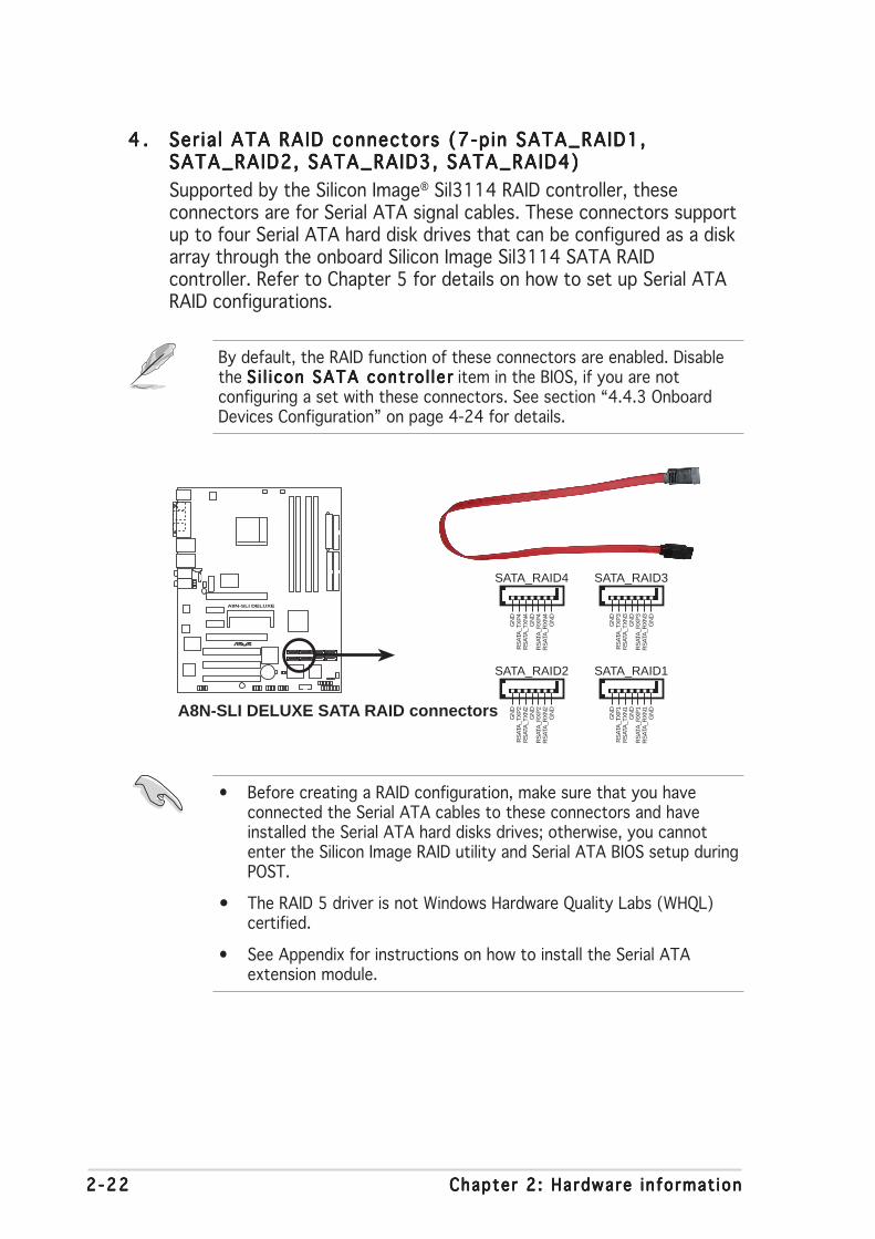
2 -222 -222 -222 -222 -22 Chapter 2 : Hardware in format ionChapter 2 : Hardware in format ionChapter 2 : Hardware in format ionChapter 2 : Hardware in format ionChapter 2 : Hardware in format ion
4 .4 .4 .4 .4 . Ser ia l ATA RAID connectors (7-pin SATA_RAID1,Ser ia l ATA RAID connectors (7-pin SATA_RAID1,Ser ia l ATA RAID connectors (7-pin SATA_RAID1,Ser ia l ATA RAID connectors (7-pin SATA_RAID1,Ser ia l ATA RAID connectors (7-pin SATA_RAID1,SATA_RAID2, SATA_RAID3, SATA_RAID4)SATA_RAID2, SATA_RAID3, SATA_RAID4)SATA_RAID2, SATA_RAID3, SATA_RAID4)SATA_RAID2, SATA_RAID3, SATA_RAID4)SATA_RAID2, SATA_RAID3, SATA_RAID4)
Supported by the Silicon Image® Sil3114 RAID controller, theseconnectors are for Serial ATA signal cables. These connectors supportup to four Serial ATA hard disk drives that can be configured as a diskarray through the onboard Silicon Image Sil3114 SATA RAIDcontroller. Refer to Chapter 5 for details on how to set up Serial ATARAID configurations.
• Before creating a RAID configuration, make sure that you haveconnected the Serial ATA cables to these connectors and haveinstalled the Serial ATA hard disks drives; otherwise, you cannotenter the Silicon Image RAID utility and Serial ATA BIOS setup duringPOST.
• The RAID 5 driver is not Windows Hardware Quality Labs (WHQL)certified.
• See Appendix for instructions on how to install the Serial ATAextension module.
A8N-SLI DELUXE
®
A8N-SLI DELUXE SATA RAID connectors
SATA_RAID2
GN
DR
SAT
A_T
XP
2R
SAT
A_T
XN
2G
ND
RS
ATA
_RX
P2
RS
ATA
_RX
N2
GN
D
SATA_RAID4
GN
DR
SAT
A_T
XP
4R
SAT
A_T
XN
4G
ND
RS
ATA
_RX
P4
RS
ATA
_RX
N4
GN
D
SATA_RAID1
GN
DR
SAT
A_T
XP
1R
SAT
A_T
XN
1G
ND
RS
ATA
_RX
P1
RS
ATA
_RX
N1
GN
D
SATA_RAID3
GN
DR
SAT
A_T
XP
3R
SAT
A_T
XN
3G
ND
RS
ATA
_RX
P3
RS
ATA
_RX
N3
GN
D
By default, the RAID function of these connectors are enabled. Disablethe S i l i con SATA contro l le rS i l i con SATA contro l le rS i l i con SATA contro l le rS i l i con SATA contro l le rS i l i con SATA contro l le r item in the BIOS, if you are notconfiguring a set with these connectors. See section “4.4.3 OnboardDevices Configuration” on page 4-24 for details.

ASUS A8N-SL I De luxeASUS A8N-SL I De luxeASUS A8N-SL I De luxeASUS A8N-SL I De luxeASUS A8N-SL I De luxe 2 -232 -232 -232 -232 -23
5 .5 .5 .5 .5 . CPU, Chass is , Chipset and Power fan connectorsCPU, Chass is , Chipset and Power fan connectorsCPU, Chass is , Chipset and Power fan connectorsCPU, Chass is , Chipset and Power fan connectorsCPU, Chass is , Chipset and Power fan connectors(3-pin CPU_FAN, 3-pin CHA2_FAN, 3-pin CHIP_FAN,(3-pin CPU_FAN, 3-pin CHA2_FAN, 3-pin CHIP_FAN,(3-pin CPU_FAN, 3-pin CHA2_FAN, 3-pin CHIP_FAN,(3-pin CPU_FAN, 3-pin CHA2_FAN, 3-pin CHIP_FAN,(3-pin CPU_FAN, 3-pin CHA2_FAN, 3-pin CHIP_FAN, 3-p in PWR_FAN, 3-p in CHA1_FAN) 3-pin PWR_FAN, 3-p in CHA1_FAN) 3-pin PWR_FAN, 3-p in CHA1_FAN) 3-pin PWR_FAN, 3-p in CHA1_FAN) 3-pin PWR_FAN, 3-p in CHA1_FAN)
The fan connectors support cooling fans of 350mA~2000mA (24 Wmax.) or a total of 1A~3.48A (41.76 W max.) at +12V. Connect thefan cables to the fan connectors on the motherboard, making sure thatthe black wire of each cable matches the ground pin of the connector.
• Do not forget to connect the fan cables to the fan connectors. Lackof sufficient air flow inside the system may damage themotherboard components. These are not jumpers! DO NOT placejumper caps on the fan connectors!
• The ASUS Q-Fan function is supported using the CPU Fan (CPU_FAN)and Chassis Fan 1 (CHA1_FAN) connectors only.
• The chipset fan is synchronized with the CPU fan.
A8N-SLI DELUXE
®
A8N-SLI DELUXE Fan connectors
CPU_FAN
CHA1_FAN
PWR_FAN
CHA2_FAN
GN
D
Rot
atio
n+
12V
GN
D
Rot
atio
n+
12V
GND
Rotation+12V
GND
Rotation+12V
CPU_FAN
CHA1_FAN
PWR_FAN
CHA2_FAN
CHIP_FAN
GN
D
Rotation
+12V
CHIP_FAN

2 -242 -242 -242 -242 -24 Chapter 2 : Hardware in format ionChapter 2 : Hardware in format ionChapter 2 : Hardware in format ionChapter 2 : Hardware in format ionChapter 2 : Hardware in format ion
6 .6 .6 .6 .6 . Ser ia l port connector (10-1 pin COM1)Ser ia l port connector (10-1 pin COM1)Ser ia l port connector (10-1 pin COM1)Ser ia l port connector (10-1 pin COM1)Ser ia l port connector (10-1 pin COM1)
This connector is for a serial (COM) port. Connect the serial portmodule cable to this connector, then install the module to a slotopening at the back of the system chassis.
Never connect a 1394 cab le1394 cab le1394 cab le1394 cab le1394 cab le to the USB connectors. Doing so willdamage the motherboard!
7 .7 .7 .7 .7 . USB connectors (10-1 pin USB56, USB78, USB910)USB connectors (10-1 pin USB56, USB78, USB910)USB connectors (10-1 pin USB56, USB78, USB910)USB connectors (10-1 pin USB56, USB78, USB910)USB connectors (10-1 pin USB56, USB78, USB910)
These connectors are for USB 2.0 ports. Connect the USB/GAMEmodule cable to any of these connectors, then install the module to aslot opening at the back of the system chassis. These USB connectorscomply with USB 2.0 specification that supports up to 480 Mbpsconnection speed.
A8N-SLI DELUXE
®
A8N-SLI DELUXE COM port connector
PIN 1
COM1
A8N-SLI DELUXE
®
A8N-SLI DELUXEUSB 2.0 connectors
USB56
US
B+
5VU
SB
_P6-
US
B_P
6+G
ND
NC
US
B+
5VU
SB
_P5-
US
B_P
5+G
ND
1USB78
US
B+
5VU
SB
_P8-
US
B_P
8+G
ND
NC
US
B+
5VU
SB
_P7-
US
B_P
7+G
ND
1USB910
US
B+
5VU
SB
_P10
-U
SB
_P10
+G
ND
NC
US
B+
5VU
SB
_P9-
US
B_P
9+G
ND
1

ASUS A8N-SL I De luxeASUS A8N-SL I De luxeASUS A8N-SL I De luxeASUS A8N-SL I De luxeASUS A8N-SL I De luxe 2 -252 -252 -252 -252 -25
8 .8 .8 .8 .8 . ATX power connectors (24-pin EATXPWR1,ATX power connectors (24-pin EATXPWR1,ATX power connectors (24-pin EATXPWR1,ATX power connectors (24-pin EATXPWR1,ATX power connectors (24-pin EATXPWR1,4-pin ATX12V1, 4-p in EZ_PLUG)4-pin ATX12V1, 4-p in EZ_PLUG)4-pin ATX12V1, 4-p in EZ_PLUG)4-pin ATX12V1, 4-p in EZ_PLUG)4-pin ATX12V1, 4-p in EZ_PLUG)
These connectors are for an ATX power supply plugs. The powersupply plugs are designed to fit these connectors in only oneorientation. Find the proper orientation and push down firmly until theconnectors completely fit.
• Do not forget to connect the 4-pin ATX +12 V power plug;otherwise, the system will not boot.
• When using two graphics cards, do not forget to connect the 4-pinATX +12 V power plug to the EZ Plug™; otherwise, the system willbe unstable. See page 6-5 for details.
• Use of a PSU with a higher power output is recommended whenconfiguring a system with more power-consuming devices. Thesystem may become unstable or may not boot up if the power isinadequate.
• Make sure that your power supply unit (PSU) can provide at leastthe minimum power required by your system. See the table belowfor details.
A8N-SLI DELUXE
®
A8N-SLI DELUXE ATX power connectors
EATXPWRATX12V
+12V DC GND
+12V DC GND
+3 Volts+3 VoltsGround+5 Volts
+5 VoltsGround
GroundPower OK+5V Standby+12 Volts
-5 Volts
+5 Volts
+3 Volts-12 VoltsGround
GroundGroundPSON#
Ground
+5 Volts
+12 Volts+3 Volts
+5 VoltsGround
EZ_PLUG
+5VEZ_DETGND+12V
Power supply requirementsPower supply requirementsPower supply requirementsPower supply requirementsPower supply requirements
L o a d i n gL o a d i n gL o a d i n gL o a d i n gL o a d i n gComponents/Pe r i phe ra l sComponents/Pe r i phe ra l sComponents/Pe r i phe ra l sComponents/Pe r i phe ra l sComponents/Pe r i phe ra l s H e a v yH e a v yH e a v yH e a v yH e a v y N o r m a lN o r m a lN o r m a lN o r m a lN o r m a l L i g h tL i g h tL i g h tL i g h tL i g h t
AMD® K8 939-pin CPU type Athlon 64 FX-55 Athlon 64 3800+ Athlon 64 3400+
PCIe™ x16 graphics cards 6800 Ultra x2 6800GT x2 6600GT x2
DDR DIMMs 4 2 2
HDD 4 2 2
Optical drive (DVD/CD-RW) 2 2 1
PCIe™ x 1 card 1 0 0
PCI cards 3 2 1
IEEE 1394 devices 1 0 0
USB devices 6 4 3
Required +12V current > 2 5 A> 2 5 A> 2 5 A> 2 5 A> 2 5 A > 2 0 A> 2 0 A> 2 0 A> 2 0 A> 2 0 A > 1 7 A> 1 7 A> 1 7 A> 1 7 A> 1 7 A
Required wattage >= 500W>= 500W>= 500W>= 500W>= 500W >= 400W>= 400W>= 400W>= 400W>= 400W >= 350W>= 350W>= 350W>= 350W>= 350W

2 -262 -262 -262 -262 -26 Chapter 2 : Hardware in format ionChapter 2 : Hardware in format ionChapter 2 : Hardware in format ionChapter 2 : Hardware in format ionChapter 2 : Hardware in format ion
9 .9 .9 .9 .9 . Internal audio connectors (4-pin CD, AUX)Internal audio connectors (4-pin CD, AUX)Internal audio connectors (4-pin CD, AUX)Internal audio connectors (4-pin CD, AUX)Internal audio connectors (4-pin CD, AUX)
These connectors allow you to receive stereo audio input from soundsources such as a CD-ROM, TV-tuner, or MPEG card.
10 .10 .10 .10 .10 . GAME/MIDI port connector (16-1 pin GAME)GAME/MIDI port connector (16-1 pin GAME)GAME/MIDI port connector (16-1 pin GAME)GAME/MIDI port connector (16-1 pin GAME)GAME/MIDI port connector (16-1 pin GAME)
This connector is for a GAME/MIDI port. Connect the USB/GAMEmodule cable to this connector, then install the module to a slotopening at the back of the system chassis. The GAME/MIDI portconnects a joystick or game pad for playing games, and MIDI devicesfor playing or editing audio files.
A8N-SLI DELUXE
®
A8N-SLI DELUXE Internal audio connectors
AUX(white)
CD(black)
Right Audio Channel
Left Audio ChannelGroundGround
Rig
ht A
udio
Cha
nnel
Left
Aud
io C
hann
elG
roun
dG
roun
d
A8N-SLI DELUXE
®
A8N-SLI DELUXE Game connector
GAME
+5V
+5V
J2B
1J2
CX
MID
I_O
UT
J2C
YJ2
B2
MID
I_IN
J1B
1J1
CX
GN
DG
ND
J1C
YJ1
B2
+5V
The function of these connectors are disabled under 8-channel mode.

ASUS A8N-SL I De luxeASUS A8N-SL I De luxeASUS A8N-SL I De luxeASUS A8N-SL I De luxeASUS A8N-SL I De luxe 2 -272 -272 -272 -272 -27
11 .11 .11 .11 .11 . Chass is intrus ion connector (4-1 pin CHASSIS)Chass is intrus ion connector (4-1 pin CHASSIS)Chass is intrus ion connector (4-1 pin CHASSIS)Chass is intrus ion connector (4-1 pin CHASSIS)Chass is intrus ion connector (4-1 pin CHASSIS)
This connector is for a chassis-mounted intrusion detection sensor orswitch. Connect one end of the chassis intrusion sensor or switchcable to this connector. The chassis intrusion sensor or switch sends ahigh-level signal to this connector when a chassis component isremoved or replaced. The signal is then generated as a chassisintrusion event.
By default, the pins labeled “Chassis Signal” and “Ground” are shortedwith a jumper cap. Remove the jumper caps only when you intend touse the chassis intrusion detection feature. See related BIOS item inpage 4-42.
Never connect a USB cab le USB cab le USB cab le USB cab le USB cab le to the IEEE 1394 connectors. Doing so willdamage the motherboard!
12 .12 .12 .12 .12 . IEEE 1394 connector (10-1 pin IE1394_2)IEEE 1394 connector (10-1 pin IE1394_2)IEEE 1394 connector (10-1 pin IE1394_2)IEEE 1394 connector (10-1 pin IE1394_2)IEEE 1394 connector (10-1 pin IE1394_2)
This connector is for the IEEE 1394a module. Connect the IEEE 1394module cable to this connector, then install the module to a slotopening at the back of the system chassis.
A8N-SLI DELUXE
®
A8N-SLI DELUXE Chassis alarm lead
CHASSIS
+5V
SB
_MB
Cha
ssis
Sig
nal
GN
D
(Default)
A8N-SLI DELUXE
®
A8N-SLI DELUXE IEEE 1394 connector
IE_1394_21
GN
D+
12V
TP
B1-
GN
DT
PA
1-
+12
VT
PB
1+G
ND
TP
A1+
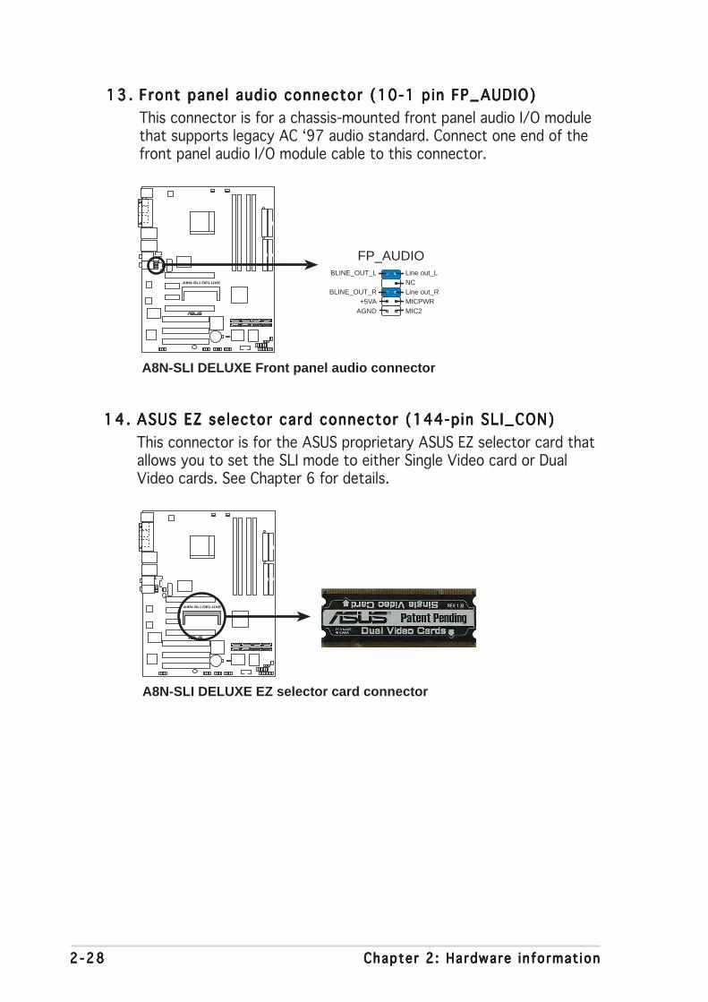
2 -282 -282 -282 -282 -28 Chapter 2 : Hardware in format ionChapter 2 : Hardware in format ionChapter 2 : Hardware in format ionChapter 2 : Hardware in format ionChapter 2 : Hardware in format ion
13 .13 .13 .13 .13 . Front panel audio connector (10-1 pin FP_AUDIO)Front panel audio connector (10-1 pin FP_AUDIO)Front panel audio connector (10-1 pin FP_AUDIO)Front panel audio connector (10-1 pin FP_AUDIO)Front panel audio connector (10-1 pin FP_AUDIO)
This connector is for a chassis-mounted front panel audio I/O modulethat supports legacy AC ‘97 audio standard. Connect one end of thefront panel audio I/O module cable to this connector.
14 .14 .14 .14 .14 . ASUS EZ selector card connector (144-pin SLI_CON)ASUS EZ selector card connector (144-pin SLI_CON)ASUS EZ selector card connector (144-pin SLI_CON)ASUS EZ selector card connector (144-pin SLI_CON)ASUS EZ selector card connector (144-pin SLI_CON)
This connector is for the ASUS proprietary ASUS EZ selector card thatallows you to set the SLI mode to either Single Video card or DualVideo cards. See Chapter 6 for details.
A8N-SLI DELUXE
®
A8N-SLI DELUXE Front panel audio connector
FP_AUDIOBLINE_OUT_L
MIC2
Line out_R
Line out_L
BLINE_OUT_RNC
MICPWR+5VAAGND
A8N-SLI DELUXE
®
A8N-SLI DELUXE EZ selector card connector
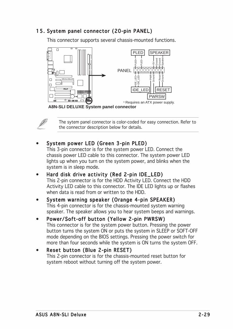
ASUS A8N-SL I De luxeASUS A8N-SL I De luxeASUS A8N-SL I De luxeASUS A8N-SL I De luxeASUS A8N-SL I De luxe 2 -292 -292 -292 -292 -29
15 .15 .15 .15 .15 . System panel connector (20-pin PANEL)System panel connector (20-pin PANEL)System panel connector (20-pin PANEL)System panel connector (20-pin PANEL)System panel connector (20-pin PANEL)
This connector supports several chassis-mounted functions.
The sytem panel connector is color-coded for easy connection. Refer tothe connector description below for details.
• System power LED (Green 3-pin PLED)System power LED (Green 3-pin PLED)System power LED (Green 3-pin PLED)System power LED (Green 3-pin PLED)System power LED (Green 3-pin PLED)This 3-pin connector is for the system power LED. Connect thechassis power LED cable to this connector. The system power LEDlights up when you turn on the system power, and blinks when thesystem is in sleep mode.
• Hard d isk dr ive act iv ity (Red 2-pin IDE_LED)Hard d isk dr ive act iv ity (Red 2-pin IDE_LED)Hard d isk dr ive act iv ity (Red 2-pin IDE_LED)Hard d isk dr ive act iv ity (Red 2-pin IDE_LED)Hard d isk dr ive act iv ity (Red 2-pin IDE_LED)This 2-pin connector is for the HDD Activity LED. Connect the HDDActivity LED cable to this connector. The IDE LED lights up or flasheswhen data is read from or written to the HDD.
• System warning speaker (Orange 4-pin SPEAKER)System warning speaker (Orange 4-pin SPEAKER)System warning speaker (Orange 4-pin SPEAKER)System warning speaker (Orange 4-pin SPEAKER)System warning speaker (Orange 4-pin SPEAKER)This 4-pin connector is for the chassis-mounted system warningspeaker. The speaker allows you to hear system beeps and warnings.
• Power/Soft-off button (Yel low 2-pin PWRSW)Power/Soft-off button (Yel low 2-pin PWRSW)Power/Soft-off button (Yel low 2-pin PWRSW)Power/Soft-off button (Yel low 2-pin PWRSW)Power/Soft-off button (Yel low 2-pin PWRSW)This connector is for the system power button. Pressing the powerbutton turns the system ON or puts the system in SLEEP or SOFT-OFFmode depending on the BIOS settings. Pressing the power switch formore than four seconds while the system is ON turns the system OFF.
• Reset button (Blue 2-pin RESET)Reset button (Blue 2-pin RESET)Reset button (Blue 2-pin RESET)Reset button (Blue 2-pin RESET)Reset button (Blue 2-pin RESET)This 2-pin connector is for the chassis-mounted reset button forsystem reboot without turning off the system power.
A8N-SLI DELUXE
®
A8N-SLI DELUXE System panel connector* Requires an ATX power supply.
PANEL
PLE
D-
PW
R+
5V Spe
aker
Gro
und
RESET
Gro
und
Res
etG
roun
dG
roun
d
PWRSW
PLE
D+
IDE
_LE
D-
IDE
_LE
D+
IDE_LED
PLED SPEAKER

2 -302 -302 -302 -302 -30 Chapter 2 : Hardware in format ionChapter 2 : Hardware in format ionChapter 2 : Hardware in format ionChapter 2 : Hardware in format ionChapter 2 : Hardware in format ion

3Powering up
This chapter describes the power upsequence, the vocal POST messages,and ways of shutting down thesystem.

ASUS A8N-SLI DeluxeASUS A8N-SLI DeluxeASUS A8N-SLI DeluxeASUS A8N-SLI DeluxeASUS A8N-SLI Deluxe
Chapter summary
3.1 Starting up for the first time ................................................ 3-1
3.2 Powering off the computer .................................................. 3-2
3.3 ASUS POST Reporter™ .......................................................... 3-3
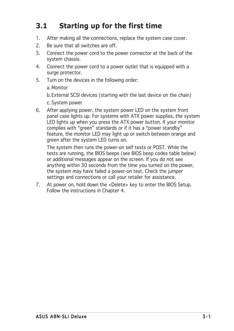
ASUS A8N-SL I De luxeASUS A8N-SL I De luxeASUS A8N-SL I De luxeASUS A8N-SL I De luxeASUS A8N-SL I De luxe 3 - 13 - 13 - 13 - 13 - 1
3.1 Starting up for the first time
1. After making all the connections, replace the system case cover.
2. Be sure that all switches are off.
3. Connect the power cord to the power connector at the back of thesystem chassis.
4. Connect the power cord to a power outlet that is equipped with asurge protector.
5. Turn on the devices in the following order:
a. Monitor
b.External SCSI devices (starting with the last device on the chain)
c. System power
6. After applying power, the system power LED on the system frontpanel case lights up. For systems with ATX power supplies, the systemLED lights up when you press the ATX power button. If your monitorcomplies with “green” standards or if it has a “power standby”feature, the monitor LED may light up or switch between orange andgreen after the system LED turns on.
The system then runs the power-on self tests or POST. While thetests are running, the BIOS beeps (see BIOS beep codes table below)or additional messages appear on the screen. If you do not seeanything within 30 seconds from the time you turned on the power,the system may have failed a power-on test. Check the jumpersettings and connections or call your retailer for assistance.
7. At power on, hold down the <Delete> key to enter the BIOS Setup.Follow the instructions in Chapter 4.

3 - 23 - 23 - 23 - 23 - 2 Chapter 3 : Power ing upChapter 3 : Power ing upChapter 3 : Power ing upChapter 3 : Power ing upChapter 3 : Power ing up
3.2 Powering off the computer
3.2.13.2.13.2.13.2.13.2.1 Using the OS shut down functionUsing the OS shut down functionUsing the OS shut down functionUsing the OS shut down functionUsing the OS shut down function
If you are using Windows® 2000:
1. Click the Start Start Start Start Start button then click Shut Down. . .Shut Down. . .Shut Down. . .Shut Down. . .Shut Down. . .
2. Make sure that the Shut DownShut DownShut DownShut DownShut Down option button is selected, then clickthe OK OK OK OK OK button to shut down the computer.
3. The power supply should turn off after Windows® shuts down.
If you are using Windows® XP:
1. Click the Start Start Start Start Start button then select Turn Off Computer .Turn Off Computer .Turn Off Computer .Turn Off Computer .Turn Off Computer .
2. Click the Turn Off Turn Off Turn Off Turn Off Turn Off button to shut down the computer.
3. The power supply should turn off after Windows® shuts down.
3.2.23.2.23.2.23.2.23.2.2 Using the dual function power switchUsing the dual function power switchUsing the dual function power switchUsing the dual function power switchUsing the dual function power switch
While the system is ON, pressing the power switch for less than fourseconds puts the system to sleep mode or to soft-off mode, depending onthe BIOS setting. Pressing the power switch for more than four secondslets the system enter the soft-off mode regardless of the BIOS setting.Refer to section “4.5 Power Menu” in Chapter 4 for details.

ASUS A8N-SL I De luxeASUS A8N-SL I De luxeASUS A8N-SL I De luxeASUS A8N-SL I De luxeASUS A8N-SL I De luxe 3 - 33 - 33 - 33 - 33 - 3
3.3 ASUS POST Reporter™
This motherboard includes the Winbond speech controller to support aspecial feature called the ASUS POST Reporter™. This feature lets you hearvocal messages during POST that alerts you of system events and bootstatus. In case of a boot failure, you will hear the specific cause of theproblem.
These POST messages are customizable using the Winbond Voice Editorsoftware that came with your package. You can record your own messagesto replace the default messages.
3.3.13.3.13.3.13.3.13.3.1 Vocal POST messagesVocal POST messagesVocal POST messagesVocal POST messagesVocal POST messages
Following is a list of the default POST messages and the correspondingactions you can take:
POST MessagePOST MessagePOST MessagePOST MessagePOST Message A c t i o nA c t i o nA c t i o nA c t i o nA c t i o n
No CPU installed • Install a supported processor to theCPU socket. See section “2.3 CentralProcessing Unit (CPU)” for details.
System failed CPU test • Check the CPU if properly installed.
• Call ASUS technical support forassistance. See the ASUS contactinformation on the inside front coverof this user guide.
System failed memory test • Install supported DDR DIMMs into thememory sockets.
• Check if the DIMMs on the DIMMsockets are properly installed.
• Make sure that your DIMMs are notdefective.
• Refer to section “2.4 System memory”for instructions on installing a DIMM.
System failed VGA test • Install a PCI graphics card into one ofthe PCI slots, or a PCI Express AGPcard into the PCI Express x16 slot.
• Make sure that your graphics card isnot defective.
System failed due to CPU • Check your CPU overclocking settingsin the BIOS setup and restore thedefault CPU parameters.
No keyboard detected • Check if your keyboard is properlyconnected to the purple PS/2connector on the rear panel.
• See section “2.7.1 Rear panelconnectors” for the location of theconnector.
No IDE hard disk detected • Make sure you have connected an IDEhard disk drive to one of the IDEconnectors on the motherboard.
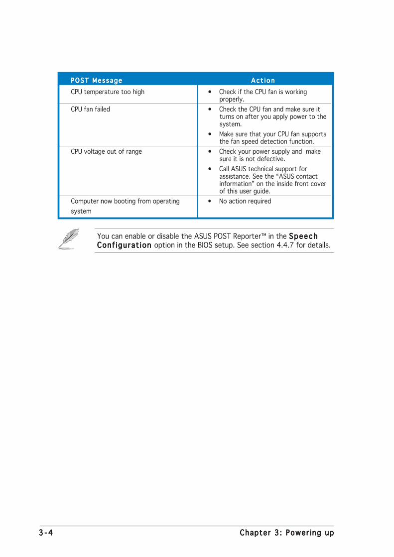
3 - 43 - 43 - 43 - 43 - 4 Chapter 3 : Power ing upChapter 3 : Power ing upChapter 3 : Power ing upChapter 3 : Power ing upChapter 3 : Power ing up
POST MessagePOST MessagePOST MessagePOST MessagePOST Message A c t i o nA c t i o nA c t i o nA c t i o nA c t i o n
CPU temperature too high • Check if the CPU fan is workingproperly.
CPU fan failed • Check the CPU fan and make sure itturns on after you apply power to thesystem.
• Make sure that your CPU fan supportsthe fan speed detection function.
CPU voltage out of range • Check your power supply and makesure it is not defective.
• Call ASUS technical support forassistance. See the “ASUS contactinformation” on the inside front coverof this user guide.
Computer now booting from operating • No action required
system
You can enable or disable the ASUS POST Reporter™ in the SpeechSpeechSpeechSpeechSpeechConf igurat ion Conf igurat ion Conf igurat ion Conf igurat ion Conf igurat ion option in the BIOS setup. See section 4.4.7 for details.
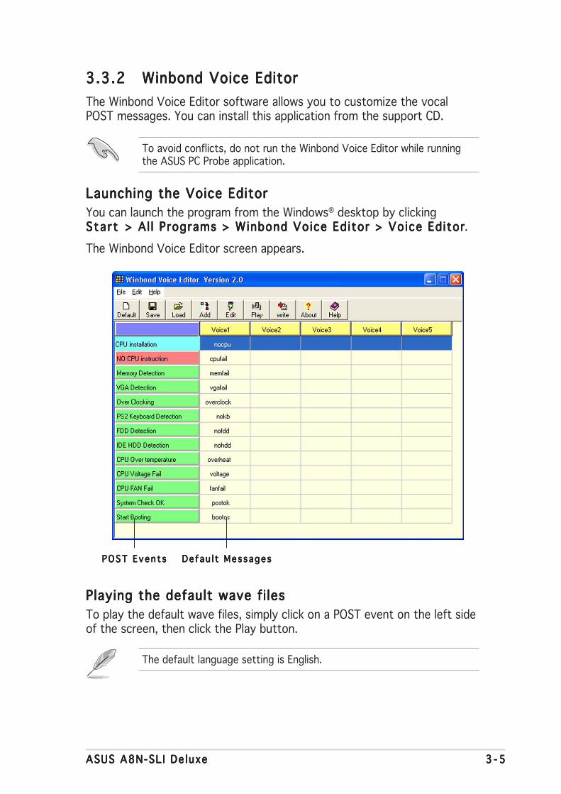
ASUS A8N-SL I De luxeASUS A8N-SL I De luxeASUS A8N-SL I De luxeASUS A8N-SL I De luxeASUS A8N-SL I De luxe 3 - 53 - 53 - 53 - 53 - 5
3.3.23.3.23.3.23.3.23.3.2 Winbond Voice EditorWinbond Voice EditorWinbond Voice EditorWinbond Voice EditorWinbond Voice Editor
The Winbond Voice Editor software allows you to customize the vocalPOST messages. You can install this application from the support CD.
Launching the Voice EditorLaunching the Voice EditorLaunching the Voice EditorLaunching the Voice EditorLaunching the Voice Editor
You can launch the program from the Windows® desktop by clickingSta r tSta r tSta r tSta r tSta r t > Al l Programs > Winbond Voice Editor > Voice Editor> Al l Programs > Winbond Voice Editor > Voice Editor> Al l Programs > Winbond Voice Editor > Voice Editor> Al l Programs > Winbond Voice Editor > Voice Editor> Al l Programs > Winbond Voice Editor > Voice Editor.
The Winbond Voice Editor screen appears.
Playing the default wave fi lesPlaying the default wave fi lesPlaying the default wave fi lesPlaying the default wave fi lesPlaying the default wave fi les
To play the default wave files, simply click on a POST event on the left sideof the screen, then click the Play button.
De fau l t MessagesDe fau l t MessagesDe fau l t MessagesDe fau l t MessagesDe fau l t MessagesPOST Even t sPOST Even t sPOST Even t sPOST Even t sPOST Even t s
To avoid conflicts, do not run the Winbond Voice Editor while runningthe ASUS PC Probe application.
The default language setting is English.

3 - 63 - 63 - 63 - 63 - 6 Chapter 3 : Power ing upChapter 3 : Power ing upChapter 3 : Power ing upChapter 3 : Power ing upChapter 3 : Power ing up
3. Click the Wr i te Wr i te Wr i te Wr i te Wr i te button from the Voice Editor main window to updatethe EEPROM.
4. Click Yes Yes Yes Yes Yes to confirm.
Changing the default languageChanging the default languageChanging the default languageChanging the default languageChanging the default language
To change the default language:
1. Click the LoadLoadLoadLoadLoad button from theVoice Editor main window. Awindow with the availablelanguages appears.
2. Select your desired language,then click OpenOpenOpenOpenOpen.
The event messages for thelanguage you selected appearon the Voice Editor mainwindow.
Not all events on some languages have a corresponding message due tofile size constraints.
The next time you boot your computer, the ASUS Post Reporter announcesthe messages in the selected language.

ASUS A8N-SL I De luxeASUS A8N-SL I De luxeASUS A8N-SL I De luxeASUS A8N-SL I De luxeASUS A8N-SL I De luxe 3 - 73 - 73 - 73 - 73 - 7
Customizing your POST messagesCustomizing your POST messagesCustomizing your POST messagesCustomizing your POST messagesCustomizing your POST messages
The Voice Editor application allows you to record your own POST messagesif your language is not supported or if you wish to to replace thepre-installed wave files.
To customize your POST messages.
1. Launch the Voice Editor application and note the list of POST eventson the leftmost column of the screen.
2. Prepare your message for each event.
3. Use a recording software (e.g. Windows® Recorder) to record yourmessages, then save the messages as wave files (.WAV).
4. From the Voice Editor screen,click the Add Add Add Add Add button to displaythe Add Wave F i le Add Wave F i le Add Wave F i le Add Wave F i le Add Wave F i le window.
5. Copy the wave files that yourecorded to the database, thenclose the window when done.
• The total compressed size for all the wave files must not exceed1Mbit, so keep your messages as short as possible.
• To keep file sizes small, save your files at a low quality. For example,use 8-bit, mono quality at 22Khz sampling rate.
• Create a separate folder for your wave files so you can locate themeasily.
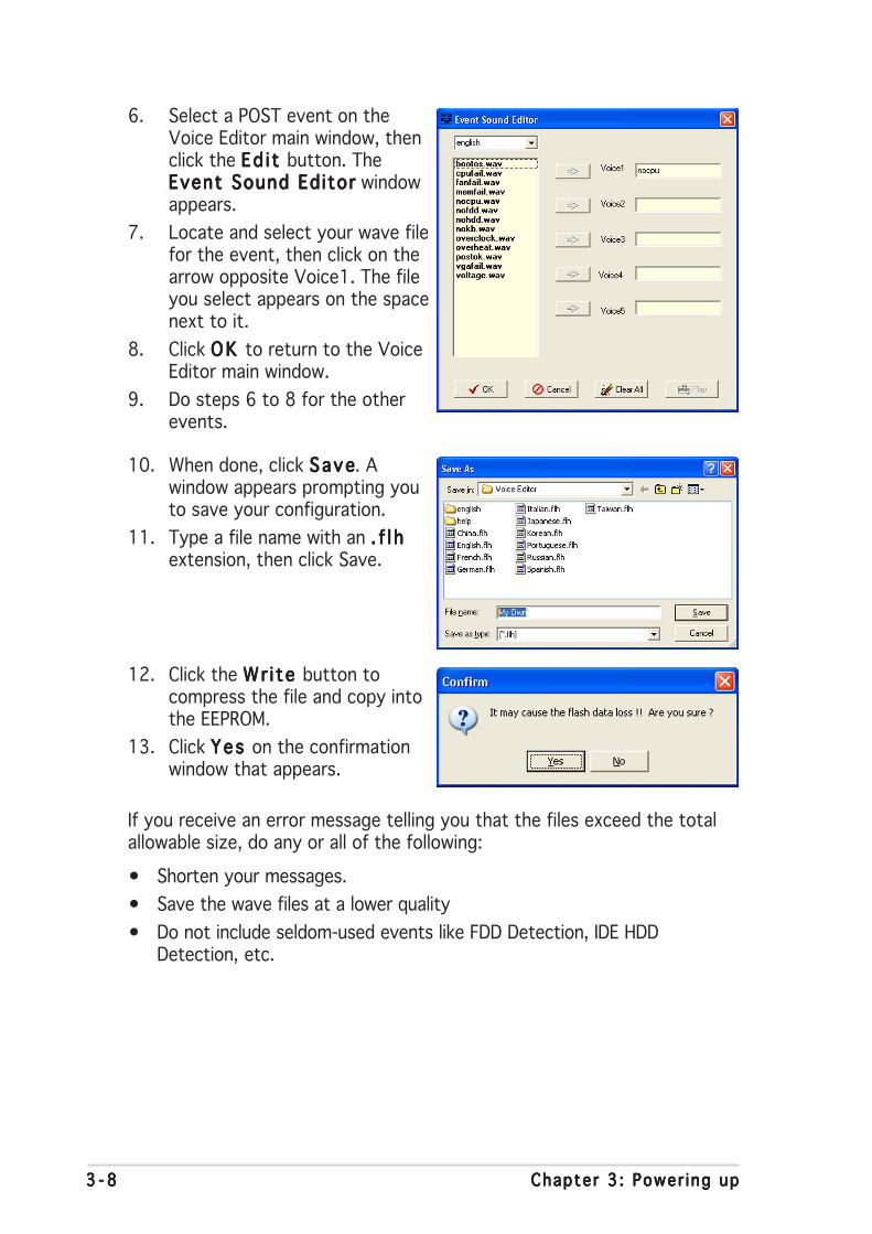
3 - 83 - 83 - 83 - 83 - 8 Chapter 3 : Power ing upChapter 3 : Power ing upChapter 3 : Power ing upChapter 3 : Power ing upChapter 3 : Power ing up
If you receive an error message telling you that the files exceed the totalallowable size, do any or all of the following:
• Shorten your messages.
• Save the wave files at a lower quality
• Do not include seldom-used events like FDD Detection, IDE HDDDetection, etc.
6. Select a POST event on theVoice Editor main window, thenclick the Ed i t Ed i t Ed i t Ed i t Ed i t button. TheEvent Sound EditorEvent Sound EditorEvent Sound EditorEvent Sound EditorEvent Sound Editor windowappears.
7. Locate and select your wave filefor the event, then click on thearrow opposite Voice1. The fileyou select appears on the spacenext to it.
8. Click OK OK OK OK OK to return to the VoiceEditor main window.
9. Do steps 6 to 8 for the otherevents.
10. When done, click SaveSaveSaveSaveSave. Awindow appears prompting youto save your configuration.
11. Type a file name with an . f l h. f l h. f l h. f l h. f l hextension, then click Save.
12. Click the Wr i te Wr i te Wr i te Wr i te Wr i te button tocompress the file and copy intothe EEPROM.
13. Click Yes Yes Yes Yes Yes on the confirmationwindow that appears.
4BIOS setup
This chapter tells how to changethe system settings through the BIOSSetup menus. Detailed descriptionsof the BIOS parameters are alsoprovided.

ASUS A8N SLI DeluxeASUS A8N SLI DeluxeASUS A8N SLI DeluxeASUS A8N SLI DeluxeASUS A8N SLI Deluxe
Chapter summary
4.1 Managing and updating your BIOS ........................................ 4-1
4.2 BIOS setup program ........................................................... 4-11
4.3 Main menu .......................................................................... 4-15
4.4 Advanced menu .................................................................. 4-20
4.5 Power menu ........................................................................ 4-35
4.6 Boot menu .......................................................................... 4-40
4.7 Exit menu ........................................................................... 4-46
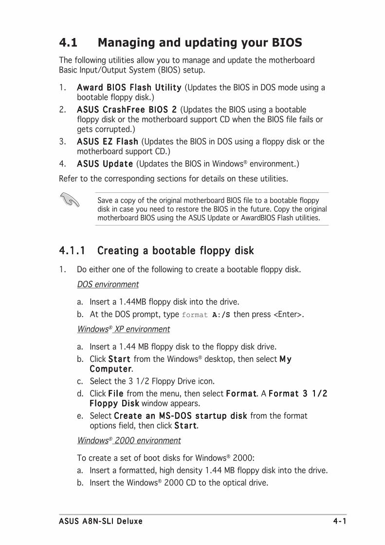
ASUS A8N-SL I De luxeASUS A8N-SL I De luxeASUS A8N-SL I De luxeASUS A8N-SL I De luxeASUS A8N-SL I De luxe 4 - 14 - 14 - 14 - 14 - 1
4.1 Managing and updating your BIOS
The following utilities allow you to manage and update the motherboardBasic Input/Output System (BIOS) setup.
1. Award BIOS F lash Ut i l i ty Award BIOS F lash Ut i l i ty Award BIOS F lash Ut i l i ty Award BIOS F lash Ut i l i ty Award BIOS F lash Ut i l i ty (Updates the BIOS in DOS mode using abootable floppy disk.)
2. ASUS CrashFree BIOS 2 ASUS CrashFree BIOS 2 ASUS CrashFree BIOS 2 ASUS CrashFree BIOS 2 ASUS CrashFree BIOS 2 (Updates the BIOS using a bootablefloppy disk or the motherboard support CD when the BIOS file fails orgets corrupted.)
3. ASUS EZ F lash ASUS EZ F lash ASUS EZ F lash ASUS EZ F lash ASUS EZ F lash (Updates the BIOS in DOS using a floppy disk or themotherboard support CD.)
4. ASUS Update ASUS Update ASUS Update ASUS Update ASUS Update (Updates the BIOS in Windows® environment.)
Refer to the corresponding sections for details on these utilities.
4.1.14.1.14.1.14.1.14.1.1 Creating a bootable floppy diskCreating a bootable floppy diskCreating a bootable floppy diskCreating a bootable floppy diskCreating a bootable floppy disk
1. Do either one of the following to create a bootable floppy disk.
DOS environment
a. Insert a 1.44MB floppy disk into the drive.
b. At the DOS prompt, type format A:/S then press <Enter>.
Windows® XP environment
a. Insert a 1.44 MB floppy disk to the floppy disk drive.
b. Click Start Start Start Start Start from the Windows® desktop, then select M yM yM yM yM yComputerComputerComputerComputerComputer.
c. Select the 3 1/2 Floppy Drive icon.
d. Click F i l e F i l e F i l e F i l e F i l e from the menu, then select FormatFormatFormatFormatFormat. A Format 3 1/2Format 3 1/2Format 3 1/2Format 3 1/2Format 3 1/2Floppy D iskF loppy D iskF loppy D iskF loppy D iskF loppy D isk window appears.
e. Select Create an MS-DOS startup d isk Create an MS-DOS startup d isk Create an MS-DOS startup d isk Create an MS-DOS startup d isk Create an MS-DOS startup d isk from the formatoptions field, then click Sta r tSta r tSta r tSta r tSta r t.
Windows® 2000 environment
To create a set of boot disks for Windows® 2000:
a. Insert a formatted, high density 1.44 MB floppy disk into the drive.
b. Insert the Windows® 2000 CD to the optical drive.
Save a copy of the original motherboard BIOS file to a bootable floppydisk in case you need to restore the BIOS in the future. Copy the originalmotherboard BIOS using the ASUS Update or AwardBIOS Flash utilities.

4 - 24 - 24 - 24 - 24 - 2 Chapter 4 : B IOS setupChapter 4 : B IOS setupChapter 4 : B IOS setupChapter 4 : B IOS setupChapter 4 : B IOS setup
c. Click Sta r tSta r tSta r tSta r tSta r t, then select R unRunRunRunRun.
d. From the Open field, type
D:\bootdisk\makeboot a:
assuming that D: is your optical drive.
e. Press <Enter>, then follow screen instructions to continue.
2. Copy the original or the latest motherboard BIOS file to the bootablefloppy disk.
4.1.24.1.24.1.24.1.24.1.2 Updating the BIOSUpdating the BIOSUpdating the BIOSUpdating the BIOSUpdating the BIOS
The Basic Input/Output System (BIOS) can be updated using theAwardBIOS Flash Utility. Follow these instructions to update the BIOS usingthis utility.
1. Download the latest BIOS file from the ASUS web site. Rename the fileto A8N-SL I .B INA8N-SLI .B INA8N-SLI .B INA8N-SLI .B INA8N-SLI .B IN and save it to a floppy disk.
Save only the updated BIOS file in the floppy disk to avoid loading thewrong BIOS file.
2. Copy the AwardBIOS Flash Utility (awdflash.exe) from the Softwarefolder of the support CD to the floppy disk with the latest BIOS file.
3. Boot the system in DOS mode using the bootable floppy disk youcreated earlier.
4. When the A : >A : >A : >A : >A : > appears, replace the bootable floppy disk with thefloppy disk containing the new BIOS file and the Award BIOS FlashUtility.
5. At the prompt, typeawdf lashawdf lashawdf lashawdf lashawdf lash then press<Enter>. The AwardBIOS Flash Utility screenappears.
AwardBIOS Flash Utility for ASUS V1.01(C) Phoenix Technologies Ltd. All Rights Reserved
Message: Please input File Name!
For NF-KC804-A8N-SLI-00 DATE: 11/18/2004Flash Type - SST 49LF004A/B /3.3V
File Name to Program:

ASUS A8N-SL I De luxeASUS A8N-SL I De luxeASUS A8N-SL I De luxeASUS A8N-SL I De luxeASUS A8N-SL I De luxe 4 - 34 - 34 - 34 - 34 - 3
6. Type the BIOS file namein the F i le Name toF i le Name toF i le Name toF i le Name toF i le Name toProgramProgramProgramProgramProgram field, thenpress <Enter>.
7. Press <N> when the utility prompts you to save the current BIOS file.The following screen appears.
8. The utility verifies theBIOS file in the floppydisk and starts flashingthe BIOS file.
Do not turn off or reset the system during the flashing process!
AwardBIOS Flash Utility for ASUS V1.01(C) Phoenix Technologies Ltd. All Rights Reserved
For NF-KC804-A8N-SLI-00 DATE: 11/18/2004Flash Type - SST 49LF004A/B /3.3V
File Name to Program: 1001.bin
AwardBIOS Flash Utility for ASUS V1.01(C) Phoenix Technologies Ltd. All Rights Reserved
Warning: Don’t Turn Off Power Or Reset System!
For NF-KC804-A8N-SLI-00 DATE: 11/18/2004Flash Type - SST 49LF004A/B /3.3V
File Name to Program: 1001.bin
Program Flashing Memory - OFE00 OK
Write OK No Update Write Fail123123123123
123456789012345678901234567890112345678901234567890123456789011234567890123456789012345678901
123123123123
123123123123
Message: Do You Want To Save Bios (Y/N)
9. The utility displays aF lash ing CompleteF lash ing CompleteF lash ing CompleteF lash ing CompleteF lash ing Completemessage indicating thatyou have successfullyflashed the BIOS file.Remove the floppy diskthen press <F1> torestart the system.
AwardBIOS Flash Utility for ASUS V1.01(C) Phoenix Technologies Ltd. All Rights Reserved
123123123123
123123123123
123123123123
F1 Reset
For NF-KC804-A8N-SLI-00 DATE: 11/18/2004Flash Type - SST 49LF004A/B /3.3V
File Name to Program: 1001.bin Flashing Complete Press <F1> to Continue
Write OK No Update Write Fail

4 - 44 - 44 - 44 - 44 - 4 Chapter 4 : B IOS setupChapter 4 : B IOS setupChapter 4 : B IOS setupChapter 4 : B IOS setupChapter 4 : B IOS setup
3. Type a filename for thecurrent BIOS file in theSave current B IOSSave current B IOSSave current B IOSSave current B IOSSave current B IOSa s a s a s a s a s field, then press<Enter>.
4. The utility saves thecurrent BIOS file to thefloppy disk, then returnsto the BIOS flashingprocess.
4.1.34.1.34.1.34.1.34.1.3 Saving the current BIOS fileSaving the current BIOS fileSaving the current BIOS fileSaving the current BIOS fileSaving the current BIOS file
You can use the AwardBIOS Flash Utility to save the current BIOS file. Youcan load the current BIOS file when the BIOS file gets corrupted during theflashing process.
AwardBIOS Flash Utility for ASUS V1.01(C) Phoenix Technologies Ltd. All Rights Reserved
Message:
For NF-KC804-A8N-SLI-00 DATE: 11/18/2004Flash Type - SST 49LF004A/B /3.3V
File Name to Program: 1001.bin
Save current BIOS as:
AwardBIOS Flash Utility for ASUS V1.01(C) Phoenix Technologies Ltd. All Rights Reserved
Message: Please Wait!
For NF-KC804-A8N-SLI-00 DATE: 11/18/2004Flash Type - SST 49LF004A/B /3.3V
File Name to Program: 1001.bin Checksum: DAD6HSave current BIOS as: old.bin
AwardBIOS Flash Utility for ASUS V1.01(C) Phoenix Technologies Ltd. All Rights Reserved
1234567890123456789012345678901123456789012345678901234567890112345678901234567890123456789011234567890123456789012345678901
Message: Please Wait!
For NF-KC804-A8N-SLI-00 DATE: 11/18/2004Flash Type - SST 49LF004A/B /3.3V
File Name to Program: 1001.bin Now Backup System BIOS to File!
To save the current BIOS file using the AwardBIOS Flash Utility:
1. Follow steps 1 to 6 ofthe previous section.
2. Press <Y> when theutility prompts you tosave the current BIOSfile. The following screenappears.
Make sure that the floppy disk has enough disk space to save the file.

ASUS A8N-SL I De luxeASUS A8N-SL I De luxeASUS A8N-SL I De luxeASUS A8N-SL I De luxeASUS A8N-SL I De luxe 4 - 54 - 54 - 54 - 54 - 5
4.1.44.1.44.1.44.1.44.1.4 ASUS CrashFree BIOS 2 utilityASUS CrashFree BIOS 2 utilityASUS CrashFree BIOS 2 utilityASUS CrashFree BIOS 2 utilityASUS CrashFree BIOS 2 utility
The ASUS CrashFree BIOS 2 is an auto recovery tool that allows you torestore the BIOS file when it fails or gets corrupted during the updatingprocess. You can update a corrupted BIOS file using the motherboardsupport CD or the floppy disk that contains the updated BIOS file.
Prepare the motherboard support CD or the floppy disk containing theupdated motherboard BIOS before using this utility.
Recovering the BIOS from the support CDRecovering the BIOS from the support CDRecovering the BIOS from the support CDRecovering the BIOS from the support CDRecovering the BIOS from the support CD
To recover the BIOS from the support CD:
1. Turn on the system.
2. Insert the motherboard support CD to the optical drive.
3. The utility displays the following message and automatically checksthe CD for the BIOS file.
4. Restart the system after the utility completes the updating process.
DO NOT shut down or reset the system while updating the BIOS! Doingso can cause system boot failure!
Award BootBlock BIOS v1.0
Copyright (c) 2000, Award Software, Inc.
BIOS ROM checksum error
Detecting IDE ATAPI device...
Found CDROM, try to Boot from it... Pass
When found, the utility reads the BIOS file and starts flashing thecorrupted BIOS file.
Award BootBlock BIOS v1.0
Copyright (c) 2000, Award Software, Inc.
BIOS ROM checksum error
Detecting IDE ATAPI device...
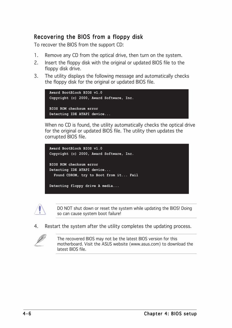
4 - 64 - 64 - 64 - 64 - 6 Chapter 4 : B IOS setupChapter 4 : B IOS setupChapter 4 : B IOS setupChapter 4 : B IOS setupChapter 4 : B IOS setup
The recovered BIOS may not be the latest BIOS version for thismotherboard. Visit the ASUS website (www.asus.com) to download thelatest BIOS file.
Recovering the BIOS from a floppy diskRecovering the BIOS from a floppy diskRecovering the BIOS from a floppy diskRecovering the BIOS from a floppy diskRecovering the BIOS from a floppy disk
To recover the BIOS from the support CD:
1. Remove any CD from the optical drive, then turn on the system.
2. Insert the floppy disk with the original or updated BIOS file to thefloppy disk drive.
3. The utility displays the following message and automatically checksthe floppy disk for the original or updated BIOS file.
4. Restart the system after the utility completes the updating process.
DO NOT shut down or reset the system while updating the BIOS! Doingso can cause system boot failure!
When no CD is found, the utility automatically checks the optical drivefor the original or updated BIOS file. The utility then updates thecorrupted BIOS file.
Award BootBlock BIOS v1.0
Copyright (c) 2000, Award Software, Inc.
BIOS ROM checksum error
Detecting IDE ATAPI device...
Found CDROM, try to Boot from it... Fail
Detecting floppy drive A media...
Award BootBlock BIOS v1.0
Copyright (c) 2000, Award Software, Inc.
BIOS ROM checksum error
Detecting IDE ATAPI device...

ASUS A8N-SL I De luxeASUS A8N-SL I De luxeASUS A8N-SL I De luxeASUS A8N-SL I De luxeASUS A8N-SL I De luxe 4 - 74 - 74 - 74 - 74 - 7
4.1.54.1.54.1.54.1.54.1.5 ASUS EZ Flash utilityASUS EZ Flash utilityASUS EZ Flash utilityASUS EZ Flash utilityASUS EZ Flash utility
The ASUS EZ Flash feature allows you to update the BIOS without having togo through the long process of booting from a floppy disk and using aDOS-based utility. The EZ Flash utility is built-in the BIOS chip so it isaccessible by pressing <Alt> + <F2> during the Power-On Self Tests(POST).
To update the BIOS using EZ Flash:
1. Visit the ASUS website (www.asus.com) to download the latest BIOSfile for the motherboard.
2. Save the BIOS file to a floppy disk, then restart the system.
3. Press <Alt> + <F2> during POST to display the following.
Insert Disk then press Enter or ESC to continue POST
4. Insert the floppy diskthat contains the BIOSfile to the floppy diskdrive then press<Enter>. The followingscreen appears.
Do not shutdown or reset the system while updating the BIOS toprevent system boot failure!
AwardBIOS Flash Utility for ASUS V1.01(C) Phoenix Technologies Ltd. All Rights Reserved
Message: Please wait...
For NF-KC804-A8N-SLI-00 DATE: 11/18/2004Flash Type - SST 49LF004A/B /3.3V
File Name to Program:
5. When the correct BIOS file is found, EZ Flash performs the BIOSupdate process and automatically reboots the system when done.
4 - 84 - 84 - 84 - 84 - 8 Chapter 4 : B IOS setupChapter 4 : B IOS setupChapter 4 : B IOS setupChapter 4 : B IOS setupChapter 4 : B IOS setup
Install ing ASUS UpdateInstall ing ASUS UpdateInstall ing ASUS UpdateInstall ing ASUS UpdateInstall ing ASUS Update
To install ASUS Update:
1. Place the support CD in the optical drive. The Dr ivers Dr ivers Dr ivers Dr ivers Dr ivers menu appears.
2. Click the Ut i l i t ies Ut i l i t ies Ut i l i t ies Ut i l i t ies Ut i l i t ies tab, then click Insta l l ASUS UpdateInsta l l ASUS UpdateInsta l l ASUS UpdateInsta l l ASUS UpdateInsta l l ASUS UpdateVX.XX.XXVX.XX.XXVX.XX.XXVX.XX.XXVX.XX.XX. See page 5-3 for the Ut i l i t ies Ut i l i t ies Ut i l i t ies Ut i l i t ies Ut i l i t ies screen menu.
3. The ASUS Update utility is copied to your system.
4.1.64.1.64.1.64.1.64.1.6 ASUS Update utilityASUS Update utilityASUS Update utilityASUS Update utilityASUS Update utility
The ASUS Update is a utility that allows you to manage, save, and updatethe motherboard BIOS in Windows® environment. The ASUS Update utilityallows you to:
• Save the current BIOS file
• Download the latest BIOS file from the Internet
• Update the BIOS from an updated BIOS file
• Update the BIOS directly from the Internet, and
• View the BIOS version information.
This utility is available in the support CD that comes with the motherboardpackage.
ASUS Update requires an Internet connection either through a networkor an Internet Service Provider (ISP).
Quit all Windows® applications before you update the BIOS using thisutility.

ASUS A8N-SL I De luxeASUS A8N-SL I De luxeASUS A8N-SL I De luxeASUS A8N-SL I De luxeASUS A8N-SL I De luxe 4 - 94 - 94 - 94 - 94 - 9
3. Select the ASUS FTP sitenearest you to avoid networktraffic, or click Auto Se lectAuto Se lectAuto Se lectAuto Se lectAuto Se lect.Click NextNextNextNextNext.
Updating the BIOS through the InternetUpdating the BIOS through the InternetUpdating the BIOS through the InternetUpdating the BIOS through the InternetUpdating the BIOS through the Internet
To update the BIOS through the Internet:
1. Launch the ASUS Update utility from the Windows® desktop by clickingStart Start Start Start Start > Programs Programs Programs Programs Programs > ASUS ASUS ASUS ASUS ASUS > ASUSUpdate ASUSUpdate ASUSUpdate ASUSUpdate ASUSUpdate > ASUSUpdateASUSUpdateASUSUpdateASUSUpdateASUSUpdate. TheASUS Update main window appears.
2. Select Update B IOS fromUpdate B IOS fromUpdate B IOS fromUpdate B IOS fromUpdate B IOS fromthe Internet the Internet the Internet the Internet the Internet option from thedrop-down menu, then clickNextNextNextNextNext.

4 -104 -104 -104 -104 -10 Chapter 4 : B IOS setupChapter 4 : B IOS setupChapter 4 : B IOS setupChapter 4 : B IOS setupChapter 4 : B IOS setup
Updating the BIOS through a BIOS fi leUpdating the BIOS through a BIOS fi leUpdating the BIOS through a BIOS fi leUpdating the BIOS through a BIOS fi leUpdating the BIOS through a BIOS fi le
To update the BIOS through a BIOS file:
1. Launch the ASUS Update utility from the Windows® desktop byclicking Start Start Start Start Start > Programs Programs Programs Programs Programs > ASUS ASUS ASUS ASUS ASUS > ASUSUpdate ASUSUpdate ASUSUpdate ASUSUpdate ASUSUpdate >ASUSUpdateASUSUpdateASUSUpdateASUSUpdateASUSUpdate. The ASUS Update main window appears.
2. Select Update B IOS from aUpdate B IOS from aUpdate B IOS from aUpdate B IOS from aUpdate B IOS from af i l e f i l e f i l e f i l e f i l e option from the drop-downmenu, then click NextNextNextNextNext.
4. From the FTP site, select theBIOS version that you wish todownload. Click Next.
5. Follow the screen instructions tocomplete the update process.
The ASUS Update utility iscapable of updating itselfthrough the Internet. Alwaysupdate the utility to avail allits features.
3. Locate the BIOS file from theOpen Open Open Open Open window, then click SaveSaveSaveSaveSave.
4. Follow the screen instructions tocomplete the update process.
ASUS A8N-SL I De luxeASUS A8N-SL I De luxeASUS A8N-SL I De luxeASUS A8N-SL I De luxeASUS A8N-SL I De luxe 4 -114 -114 -114 -114 -11
4.2 BIOS setup program
This motherboard supports a programmable Low-Pin Count (LPC) chip thatyou can update using the provided utility described in section “4.1Managing and updating your BIOS.”
Use the BIOS Setup program when you are installing a motherboard,reconfiguring your system, or prompted to “Run Setup”. This sectionexplains how to configure your system using this utility.
Even if you are not prompted to use the Setup program, you can changethe configuration of your computer in the future. For example, you canenable the security password feature or change the power managementsettings. This requires you to reconfigure your system using the BIOSSetup program so that the computer can recognize these changes andrecord them in the CMOS RAM of the LPC chip.
The LPC chip on the motherboard stores the Setup utility. When you startup the computer, the system provides you with the opportunity to run thisprogram. Press <Del> during the Power-On Self-Test (POST) to enter theSetup utility; otherwise, POST continues with its test routines.
If you wish to enter Setup after POST, restart the system by pressing<Ctrl+Alt+Delete>, or by pressing the reset button on the system chassis.You can also restart by turning the system off and then back on. Do thislast option only if the first two failed.
The Setup program is designed to make it as easy to use as possible. Beinga menu-driven program, it lets you scroll through the various sub-menusand make your selections from the available options using the navigationkeys.
• The default BIOS settings for this motherboard apply for mostconditions to ensure optimum performance. If the system becomesunstable after changing any BIOS settings, load the default settingsto ensure system compatibility and stability. Select the L o a dL o a dL o a dL o a dL o a dDefau l t Sett ingsDefau l t Sett ingsDefau l t Sett ingsDefau l t Sett ingsDefau l t Sett ings item under the Exit Menu. See section “4.7 ExitMenu.”
• The BIOS setup screens shown in this section are for referencepurposes only, and may not exactly match what you see on yourscreen.
• Visit the ASUS website (www.asus.com) to download the latest BIOSfile for this motherboard and .

4 -124 -124 -124 -124 -12 Chapter 4 : B IOS setupChapter 4 : B IOS setupChapter 4 : B IOS setupChapter 4 : B IOS setupChapter 4 : B IOS setup
F1:Help ↑↓ : Select Item -/+: Change Value F5: Setup DefaultsESC: Exit →←: Select Menu Enter: Select Sub-menu F10: Save and Exit
Phoenix-Award BIOS CMOS Setup Utility Main Advanced Power Boot Exit
Select Menu
Item Specific Help
Change the day, month,year and century.
System Time 15 : 30 : 36System Date Wed, Nov 5 2004Language [English]
Legacy Diskette A: [1.44M, 3.5 in.]
Primary IDE Master [ST321122A]Primary IDE Slave [ASUS CDS520/A]Secondary IDE Master [None]Secondary IDE Slave [None]First SATA Master [None]Second SATA Slave [None]Third SATA Master [None]Fourth SATA Slave [None]HDD SMART Monitoring [Disabled]
Installed Memory 256MB
4.2.24.2.24.2.24.2.24.2.2 Menu barMenu barMenu barMenu barMenu bar
The menu bar on top of the screen has the following main items:
Ma inMa inMa inMa inMa in For changing the basic system configuration
AdvancedAdvancedAdvancedAdvancedAdvanced For changing the advanced system settings
PowerPowerPowerPowerPower For changing the advanced power management (APM)configuration
BootBootBootBootBoot For changing the system boot configuration
Ex i tEx i tEx i tEx i tEx i t For selecting the exit options and loading default settings
To select an item on the menu bar, press the right or left arrow key on thekeyboard until the desired item is highlighted.
4.2.14.2.14.2.14.2.14.2.1 BIOS menu screenBIOS menu screenBIOS menu screenBIOS menu screenBIOS menu screen
• The BIOS setup screens shown in this chapter are for referencepurposes only, and may not exactly match what you see on yourscreen.
• Visit the ASUS website (www.asus.com) to download the latest BIOSinformation.
Legend ba rLegend ba rLegend ba rLegend ba rLegend ba r
Gene r a l he l pGene r a l he l pGene r a l he l pGene r a l he l pGene r a l he l pMenu ba rMenu ba rMenu ba rMenu ba rMenu ba r
Sub -menu i t emsSub -menu i t emsSub -menu i t emsSub -menu i t emsSub -menu i t ems
Con f i gu ra t i on f i e l d sCon f i gu ra t i on f i e l d sCon f i gu ra t i on f i e l d sCon f i gu ra t i on f i e l d sCon f i gu ra t i on f i e l d sMenu i t emsMenu i t emsMenu i t emsMenu i t emsMenu i t ems

ASUS A8N-SL I De luxeASUS A8N-SL I De luxeASUS A8N-SL I De luxeASUS A8N-SL I De luxeASUS A8N-SL I De luxe 4 -134 -134 -134 -134 -13
4.2.44.2.44.2.44.2.44.2.4 Menu itemsMenu itemsMenu itemsMenu itemsMenu items
The highlighted item on the menu bar displays the specific items for thatmenu. For example, selecting Ma in Ma in Ma in Ma in Ma in shows the Main menu items.
The other items (Advanced, Power, Boot, and Exit) on the menu bar havetheir respective menu items.
4.2.54.2.54.2.54.2.54.2.5 Sub-menu itemsSub-menu itemsSub-menu itemsSub-menu itemsSub-menu items
A solid triangle before each item on any menu screen means that the iteamhas a sub-menu. To display the sub-menu, select the item and press<Enter>.
4.2.64.2.64.2.64.2.64.2.6 Configuration fieldsConfiguration fieldsConfiguration fieldsConfiguration fieldsConfiguration fields
These fields show the values for the menu items. If an item isuser-configurable, you can change the value of the field opposite the item.You cannot select an item that is not user-configurable.
A configurable field is enclosed in brackets, and is highlighted whenselected. To change the value of a field, select it then press <Enter> todisplay a list of options. Refer to “4.2.7 Pop-up window.”
4.2.34.2.34.2.34.2.34.2.3 Legend barLegend barLegend barLegend barLegend bar
At the bottom of the Setup screen is a legend bar. The keys in the legendbar allow you to navigate through the various setup menus. The followingtable lists the keys found in the legend bar with their correspondingfunctions.
Nav igat ion KeyNav igat ion KeyNav igat ion KeyNav igat ion KeyNav igat ion Key Funct ionFunct ionFunct ionFunct ionFunct ion
< F 1 >< F 1 >< F 1 >< F 1 >< F 1 > Displays the General Help screen
< F 5 >< F 5 >< F 5 >< F 5 >< F 5 > Loads setup default values
<Esc><Esc><Esc><Esc><Esc> Exits the BIOS setup or returns to the main menufrom a sub-menu
Left or R ight a r rowLeft or R ight a r rowLeft or R ight a r rowLeft or R ight a r rowLeft or R ight a r row Selects the menu item to the left or right
Up or Down ar rowUp or Down ar rowUp or Down ar rowUp or Down ar rowUp or Down ar row Moves the highlight up or down between fields
Page Down or – (minus)Page Down or – (minus)Page Down or – (minus)Page Down or – (minus)Page Down or – (minus) Scrolls backward through the values for thehighlighted field
Page Up or + (p lus)Page Up or + (p lus)Page Up or + (p lus)Page Up or + (p lus)Page Up or + (p lus) Scrolls forward through the values for the highlightedfield
<Ente r><Ente r><Ente r><Ente r><Ente r> Brings up a selection menu for the highlighted field
<F10><F10><F10><F10><F10> Saves changes and exit
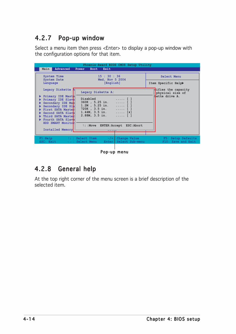
4 -144 -144 -144 -144 -14 Chapter 4 : B IOS setupChapter 4 : B IOS setupChapter 4 : B IOS setupChapter 4 : B IOS setupChapter 4 : B IOS setup
4.2.74.2.74.2.74.2.74.2.7 Pop-up windowPop-up windowPop-up windowPop-up windowPop-up window
Select a menu item then press <Enter> to display a pop-up window withthe configuration options for that item.
F1:Help ↑↓ : Select Item -/+: Change Value F5: Setup DefaultsESC: Exit →←: Select Menu Enter: Select Sub-menu F10: Save and Exit
Phoenix-Award BIOS CMOS Setup Utility Main Advanced Power Boot Exit
Select Menu
Item Specific Help
Specifies the capacityand physical size ofdiskette drive A.
System Time 15 : 30 : 36System Date Wed, Nov 5 2004Language [English]
Legacy Diskette A: [1.44M, 3.5 in.]
Primary IDE Master [ST321122A]Primary IDE Slave [ASUS CDS520/A]Secondary IDE Master [None]Secondary IDE Slave [None]First SATA Master [None]Second SATA Slave [None]Third SATA Master [None]Fourth SATA Slave [None]HDD SMART Monitoring [Disabled]
Installed Memory 256MB
4.2.84.2.84.2.84.2.84.2.8 General helpGeneral helpGeneral helpGeneral helpGeneral help
At the top right corner of the menu screen is a brief description of theselected item.
Legacy Diskette A:
Disabled ..... [ ]360K , 5.25 in. ..... [ ]1.2M , 5.25 in. ..... [ ]720K , 3.5 in. ..... [ ]1.44M, 3.5 in. ..... [ ]2.88M, 3.5 in. ..... [ ]
↑↓ :Move ENTER:Accept ESC:Abort
Pop -up menuPop -up menuPop -up menuPop -up menuPop -up menu
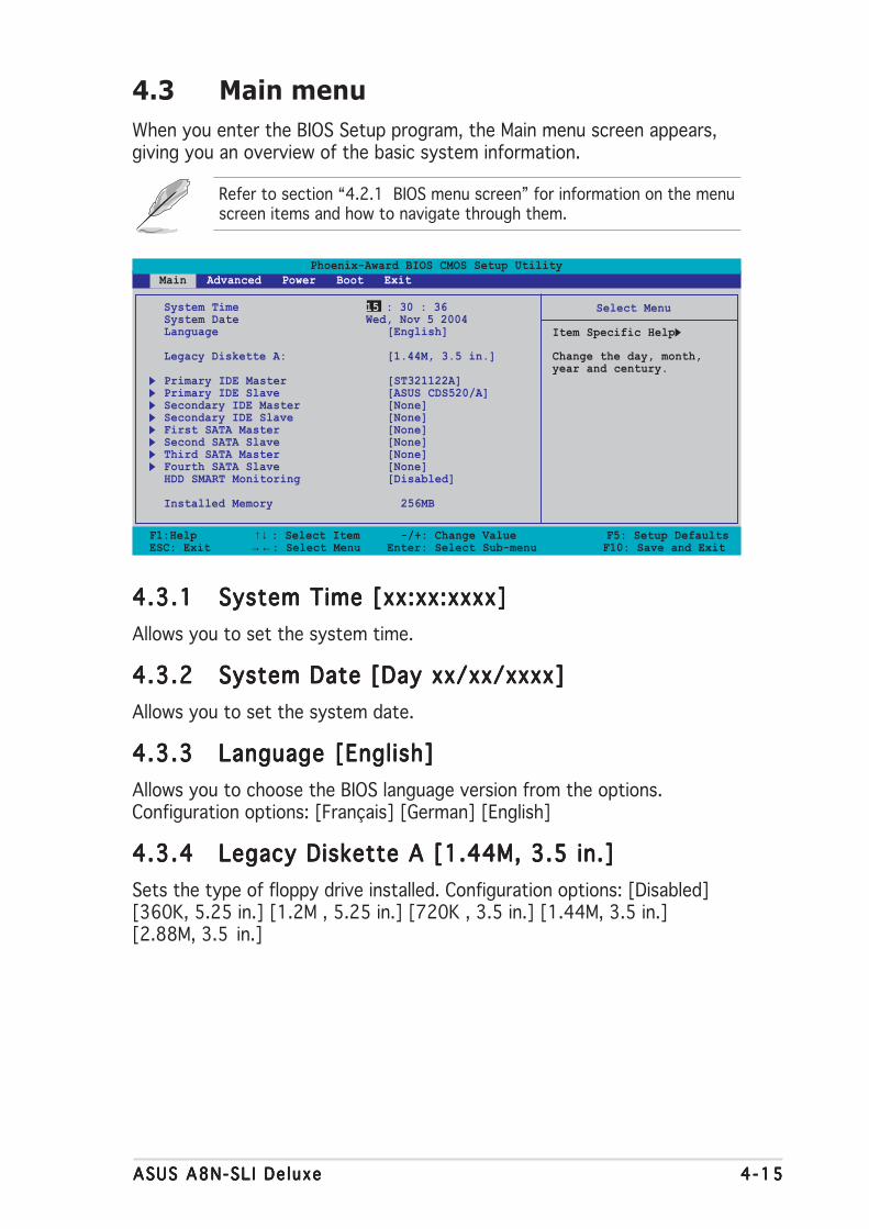
ASUS A8N-SL I De luxeASUS A8N-SL I De luxeASUS A8N-SL I De luxeASUS A8N-SL I De luxeASUS A8N-SL I De luxe 4 -154 -154 -154 -154 -15
F1:Help ↑↓ : Select Item -/+: Change Value F5: Setup DefaultsESC: Exit →←: Select Menu Enter: Select Sub-menu F10: Save and Exit
Phoenix-Award BIOS CMOS Setup Utility Main Advanced Power Boot Exit
Select Menu
Item Specific Help
Change the day, month,year and century.
System Time 15 : 30 : 36System Date Wed, Nov 5 2004Language [English]
Legacy Diskette A: [1.44M, 3.5 in.]
Primary IDE Master [ST321122A]Primary IDE Slave [ASUS CDS520/A]Secondary IDE Master [None]Secondary IDE Slave [None]First SATA Master [None]Second SATA Slave [None]Third SATA Master [None]Fourth SATA Slave [None]HDD SMART Monitoring [Disabled]
Installed Memory 256MB
4.3 Main menu
When you enter the BIOS Setup program, the Main menu screen appears,giving you an overview of the basic system information.
Refer to section “4.2.1 BIOS menu screen” for information on the menuscreen items and how to navigate through them.
4.3.14.3.14.3.14.3.14.3.1 System Time [xx:xx:xxxx]System Time [xx:xx:xxxx]System Time [xx:xx:xxxx]System Time [xx:xx:xxxx]System Time [xx:xx:xxxx]
Allows you to set the system time.
4.3.24.3.24.3.24.3.24.3.2 System Date [Day xx/xx/xxxx]System Date [Day xx/xx/xxxx]System Date [Day xx/xx/xxxx]System Date [Day xx/xx/xxxx]System Date [Day xx/xx/xxxx]
Allows you to set the system date.
4.3.34.3.34.3.34.3.34.3.3 Language [English]Language [English]Language [English]Language [English]Language [English]
Allows you to choose the BIOS language version from the options.Configuration options: [Français] [German] [English]
4.3.44.3.44.3.44.3.44.3.4 Legacy Diskette A [1.44M, 3.5 in.]Legacy Diskette A [1.44M, 3.5 in.]Legacy Diskette A [1.44M, 3.5 in.]Legacy Diskette A [1.44M, 3.5 in.]Legacy Diskette A [1.44M, 3.5 in.]
Sets the type of floppy drive installed. Configuration options: [Disabled][360K, 5.25 in.] [1.2M , 5.25 in.] [720K , 3.5 in.] [1.44M, 3.5 in.][2.88M, 3.5 in.]

4 -164 -164 -164 -164 -16 Chapter 4 : B IOS setupChapter 4 : B IOS setupChapter 4 : B IOS setupChapter 4 : B IOS setupChapter 4 : B IOS setup
4.3.54.3.54.3.54.3.54.3.5 Primary and Secondary IDE Master/SlavePrimary and Secondary IDE Master/SlavePrimary and Secondary IDE Master/SlavePrimary and Secondary IDE Master/SlavePrimary and Secondary IDE Master/Slave
While entering Setup, the BIOS automatically detects the presence of IDEdevices. There is a separate sub-menu for each IDE device. Select a deviceitem then press <Enter> to display the IDE device information.
The BIOS automatically detects the values opposite the dimmed items(Capacity, Cylinder, Head, Sector and Transfer Mode). These values are notuser-configurable. These items show N/A if no IDE device is installed in thesystem.
PIO ModePIO ModePIO ModePIO ModePIO Mode
Sets the PIO mode for the IDE device.Configuration options: [Auto] [Mode 0] [Mode 1] [Mode 2] [Mode 3][Mode 4]
UDMA ModeUDMA ModeUDMA ModeUDMA ModeUDMA Mode
Disables or sets the UDMA mode. Configuration options: [Disabled] [Auto]
IDE Primary Master/Slave [Auto]; IDE Secondary Master/IDE Primary Master/Slave [Auto]; IDE Secondary Master/IDE Primary Master/Slave [Auto]; IDE Secondary Master/IDE Primary Master/Slave [Auto]; IDE Secondary Master/IDE Primary Master/Slave [Auto]; IDE Secondary Master/Slave [Auto]Slave [Auto]Slave [Auto]Slave [Auto]Slave [Auto]
Select [Auto] to automatically detect an IDE hard disk drive. If automaticdetection is successful, the BIOS automatically fills in the correct values forthe remaining fields on this sub-menu. If the hard disk was alreadyformatted on a previous system, the setup BIOS may detect incorrectparameters. Select [Manual] to manually enter the IDE hard disk driveparameters. If no drive is installed select [None].Configuration options: [None] [Auto] [Manual]
F1:Help ↑↓ : Select Item -/+: Change Value F5: Setup DefaultsESC: Exit →←: Select Menu Enter: Select Sub-menu F10: Save and Exit
Phoenix-Award BIOS CMOS Setup Utility Main
Select Menu
Item Specific Help
Press [Enter] toselect
Primary IDE Master
PIO Mode [Auto]UDMA Mode [Auto]
Primary IDE Master [Auto]Access Mode [Auto]UDMA Mode [Auto]
Capacity 13579 MB
Cylinder 26310Head 16Sector 63Transfer Mode UDMA 4
ASUS A8N-SL I De luxeASUS A8N-SL I De luxeASUS A8N-SL I De luxeASUS A8N-SL I De luxeASUS A8N-SL I De luxe 4 -174 -174 -174 -174 -17
Before attempting to configure a hard disk drive, make sure you havethe correct configuration information supplied by the drivemanufacturer. Incorrect settings may cause the system to fail torecognize the installed hard disk.
CapacityCapacityCapacityCapacityCapacity
Displays the auto-detected hard disk capacity. This item is notconfigurable.
Cyl inderCyl inderCyl inderCyl inderCyl inder
Shows the number of the hard disk cylinders. This item is not configurable.
HeadHeadHeadHeadHead
Shows the number of the hard disk read/write heads. This item is notconfigurable.
SectorSectorSectorSectorSector
Shows the number of sectors per track. This item is not configurable.
Transfer ModeTransfer ModeTransfer ModeTransfer ModeTransfer Mode
Shows the Transfer mode. This item is not configurable.
After entering the IDE hard disk drive information into BIOS, use a diskutility, such as FDISK, to partition and format new IDE hard disk drives.This is necessary so that you can write or read data from the hard disk.Make sure to set the partition of the Primary IDE hard disk drives toactive.
Access Mode [Auto]Access Mode [Auto]Access Mode [Auto]Access Mode [Auto]Access Mode [Auto]
The default [Auto] allows automatic detection of an IDE hard disk drive.Select [CHS] for this item if you set the IDE Primary Master/Slave to[Manual]. Configuration options: [CHS] [LBA] [Large] [Auto]
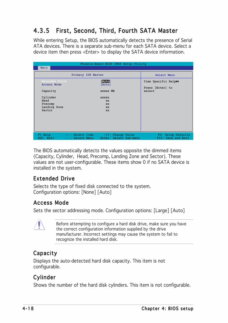
4 -184 -184 -184 -184 -18 Chapter 4 : B IOS setupChapter 4 : B IOS setupChapter 4 : B IOS setupChapter 4 : B IOS setupChapter 4 : B IOS setup
4.3.54.3.54.3.54.3.54.3.5 First, Second, Third, Fourth SATA MasterFirst, Second, Third, Fourth SATA MasterFirst, Second, Third, Fourth SATA MasterFirst, Second, Third, Fourth SATA MasterFirst, Second, Third, Fourth SATA Master
While entering Setup, the BIOS automatically detects the presence of SerialATA devices. There is a separate sub-menu for each SATA device. Select adevice item then press <Enter> to display the SATA device information.
The BIOS automatically detects the values opposite the dimmed items(Capacity, Cylinder, Head, Precomp, Landing Zone and Sector). Thesevalues are not user-configurable. These items show 0 if no SATA device isinstalled in the system.
Extended DriveExtended DriveExtended DriveExtended DriveExtended Drive
Selects the type of fixed disk connected to the system.Configuration options: [None] [Auto]
Access ModeAccess ModeAccess ModeAccess ModeAccess Mode
Sets the sector addressing mode. Configuration options: [Large] [Auto]
F1:Help ↑↓ : Select Item -/+: Change Value F5: Setup DefaultsESC: Exit →←: Select Menu Enter: Select Sub-menu F10: Save and Exit
Phoenix-Award BIOS CMOS Setup Utility Main
Select Menu
Item Specific Help
Press [Enter] toselect
Primary IDE Master
Extended Drive [Auto]Access Mode [Auto]
Capacity xxxxx MB
Cylinder xxxxxHead xxPrecomp xxLanding Zone xxSector xx
Before attempting to configure a hard disk drive, make sure you havethe correct configuration information supplied by the drivemanufacturer. Incorrect settings may cause the system to fail torecognize the installed hard disk.
CapacityCapacityCapacityCapacityCapacity
Displays the auto-detected hard disk capacity. This item is notconfigurable.
Cyl inderCyl inderCyl inderCyl inderCyl inder
Shows the number of the hard disk cylinders. This item is not configurable.

ASUS A8N-SL I De luxeASUS A8N-SL I De luxeASUS A8N-SL I De luxeASUS A8N-SL I De luxeASUS A8N-SL I De luxe 4 -194 -194 -194 -194 -19
HeadHeadHeadHeadHead
Shows the number of the hard disk read/write heads. This item is notconfigurable.
PrecompPrecompPrecompPrecompPrecomp
Shows the number of precomp per track. This item is not configurable.
Landing ZoneLanding ZoneLanding ZoneLanding ZoneLanding Zone
Shows the number of landing zone per track. This item is not configurable.
SectorSectorSectorSectorSector
Shows the number of sectors per track. This item is not configurable.
After entering the IDE hard disk drive information into BIOS, use a diskutility, such as FDISK, to partition and format new IDE hard disk drives.This is necessary so that you can write or read data from the hard disk.Make sure to set the partition of the Primary IDE hard disk drives toactive.
4.3.74.3.74.3.74.3.74.3.7 HDD SMART MonitoringHDD SMART MonitoringHDD SMART MonitoringHDD SMART MonitoringHDD SMART Monitoring
Allows you to enable or disable the HDD Self-Monitoring Analysis andReporting Technology (SMART) feature.Configuration options: [Disabled] [Enabled]
4.3.84.3.84.3.84.3.84.3.8 Installed MemoryInstalled MemoryInstalled MemoryInstalled MemoryInstalled Memory
Shows the size of installed memory.

4 -204 -204 -204 -204 -20 Chapter 4 : B IOS setupChapter 4 : B IOS setupChapter 4 : B IOS setupChapter 4 : B IOS setupChapter 4 : B IOS setup
Phoenix-Award BIOS CMOS Setup Utility Main Advanced Power Boot Exit
Select Menu
Item Specific Help
Press Enter to Set
CPU ConfigurationPCIPnPOnboard Device ConfigurationJumperFree ConfigurationLAN Cable StatusPEG Link ModeSpeech ConfigurationInstant MusicSLI mode [Auto]
4.4.14.4.14.4.14.4.14.4.1 CPU ConfigurationCPU ConfigurationCPU ConfigurationCPU ConfigurationCPU Configuration
F1:Help ↑↓ : Select Item -/+: Change Value F5: Setup DefaultsESC: Exit →←: Select Menu Enter: Select Sub-menu F10: Save and Exit
Select Menu
Item Specific Help
DRAM timing andcontrol
CPU Configuration
CPU Type AMD Athlon(tm) 64 FX-55 ProcessorCPU Speed 3400MHzCache RAM 512KDRAM ConfigurationHyper Transport Frequency [Auto]AMD K8 Cool’n’Quiet control [Auto]
Phoenix-Award BIOS CMOS Setup Utility Advanced
4.4 Advanced menu
The Advanced menu items allow you to change the settings for the CPUand other system devices.
Take caution when changing the settings of the Advanced menu items.Incorrect field values can cause the system to malfunction.
F1:Help ↑↓ : Select Item -/+: Change Value F5: Setup DefaultsESC: Exit →←: Select Menu Enter: Select Sub-menu F10: Save and Exit
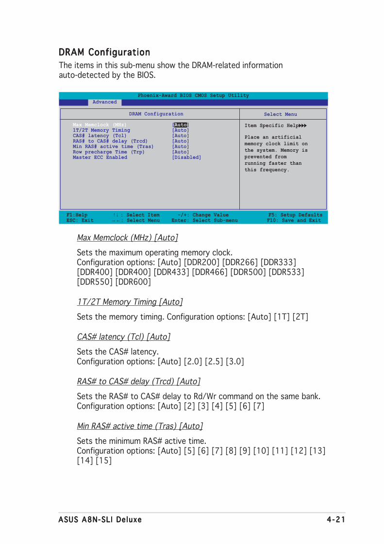
ASUS A8N-SL I De luxeASUS A8N-SL I De luxeASUS A8N-SL I De luxeASUS A8N-SL I De luxeASUS A8N-SL I De luxe 4 -214 -214 -214 -214 -21
DRAM ConfigurationDRAM ConfigurationDRAM ConfigurationDRAM ConfigurationDRAM Configuration
The items in this sub-menu show the DRAM-related informationauto-detected by the BIOS.
F1:Help ↑↓ : Select Item -/+: Change Value F5: Setup DefaultsESC: Exit →←: Select Menu Enter: Select Sub-menu F10: Save and Exit
Select Menu
Item Specific Help
Place an artificialmemory clock limit onthe system. Memory isprevented fromrunning faster thanthis frequency.
DRAM Configuration
Max Memclock (MHz) [Auto]1T/2T Memory Timing [Auto]CAS# latency (Tcl) [Auto]RAS# to CAS# delay (Trcd) [Auto]Min RAS# active time (Tras) [Auto]Row precharge Time (Trp) [Auto]Master ECC Enabled [Disabled]
Phoenix-Award BIOS CMOS Setup Utility Advanced
Max Memclock (MHz) [Auto]
Sets the maximum operating memory clock.Configuration options: [Auto] [DDR200] [DDR266] [DDR333][DDR400] [DDR400] [DDR433] [DDR466] [DDR500] [DDR533][DDR550] [DDR600]
1T/2T Memory Timing [Auto]
Sets the memory timing. Configuration options: [Auto] [1T] [2T]
CAS# latency (Tcl) [Auto]
Sets the CAS# latency.Configuration options: [Auto] [2.0] [2.5] [3.0]
RAS# to CAS# delay (Trcd) [Auto]
Sets the RAS# to CAS# delay to Rd/Wr command on the same bank.Configuration options: [Auto] [2] [3] [4] [5] [6] [7]
Min RAS# active time (Tras) [Auto]
Sets the minimum RAS# active time.Configuration options: [Auto] [5] [6] [7] [8] [9] [10] [11] [12] [13][14] [15]

4 -224 -224 -224 -224 -22 Chapter 4 : B IOS setupChapter 4 : B IOS setupChapter 4 : B IOS setupChapter 4 : B IOS setupChapter 4 : B IOS setup
Row precharge Time (Trp) [Auto]
Sets the Row precharge time. Precharge to Active or Auto-Refresh ofthe same bank. Configuration options: [Auto] [2] [3] [4] [5] [6]
Master ECC Enable [Disabled]
Enables or disables the master ECC function.Configuration options: [Disabled] [Enabled]
Hyper Transport Frequency [Auto]Hyper Transport Frequency [Auto]Hyper Transport Frequency [Auto]Hyper Transport Frequency [Auto]Hyper Transport Frequency [Auto]
Sets the Hyper Transport frequency.Configuration options: [Auto] [1x] [2x] [3x] [4x] [5x] [Auto]
AMD K8 Cool’n’Quiet control [Auto]AMD K8 Cool’n’Quiet control [Auto]AMD K8 Cool’n’Quiet control [Auto]AMD K8 Cool’n’Quiet control [Auto]AMD K8 Cool’n’Quiet control [Auto]
Enables or disables the AMD Cool ‘n’ Quiet! technology.Configuration options: [Disabled] [Enabled]

ASUS A8N-SL I De luxeASUS A8N-SL I De luxeASUS A8N-SL I De luxeASUS A8N-SL I De luxeASUS A8N-SL I De luxe 4 -234 -234 -234 -234 -23
F1:Help ↑↓ : Select Item -/+: Change Value F5: Setup DefaultsESC: Exit →←: Select Menu Enter: Select Sub-menu F10: Save and Exit
Select Menu
Item Specific Help
Frequency/Voltage control
Plug & Play O/S [No]Init Display First [PCI Slot]
Resources Controlled By [Auto]x IRQ Resources
PCI/VGA Palette Snoop [Disabled]
Phoenix-Award BIOS CMOS Setup Utility Advanced
4.4.24.4.24.4.24.4.24.4.2 PCIPnPPCIPnPPCIPnPPCIPnPPCIPnP
Plug & Play O/S [No]Plug & Play O/S [No]Plug & Play O/S [No]Plug & Play O/S [No]Plug & Play O/S [No]
When set to [No], the BIOS configures all the devices in the system. Whenset to [Yes] and if you install a Plug and Play operating system, theoperating system configures the Plug and Play devices not required forboot. Configuration options: [No] [Yes]
Resources Controlled By [Auto]Resources Controlled By [Auto]Resources Controlled By [Auto]Resources Controlled By [Auto]Resources Controlled By [Auto]
When set to [Auto], the BIOS automatically configures all the boot andPlug and Play compatible devices. Set to [Manual] if you want to assign theIRQ DMA and memory base address fields.Configuration options: [Auto] [Manual]
When the item Resources Controlled By is set to [Auto], the item IRQResources is grayed out and not user-configurable. Refer to the section“IRQ Resources” for information on how to enable this item.
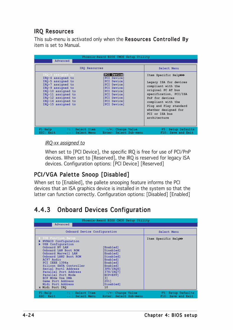
4 -244 -244 -244 -244 -24 Chapter 4 : B IOS setupChapter 4 : B IOS setupChapter 4 : B IOS setupChapter 4 : B IOS setupChapter 4 : B IOS setup
IRQ ResourcesIRQ ResourcesIRQ ResourcesIRQ ResourcesIRQ Resources
This sub-menu is activated only when the Resources Contro l led ByResources Contro l led ByResources Contro l led ByResources Contro l led ByResources Contro l led Byitem is set to Manual.
F1:Help ↑↓ : Select Item -/+: Change Value F5: Setup DefaultsESC: Exit →←: Select Menu Enter: Select Sub-menu F10: Save and Exit
Select Menu
Item Specific Help
Legacy ISA for devicescompliant with theoriginal PC AT busspecification, PCI/ISAPnP for devicescompliant with thePlug and Play standardwhether designed forPCI or ISA busarchitecture
IRQ Resources
IRQ-3 assigned to [PCI Device]IRQ-4 assigned to [PCI Device]IRQ-5 assigned to [PCI Device]IRQ-7 assigned to [PCI Device]IRQ-9 assigned to [PCI Device]IRQ-10 assigned to [PCI Device]IRQ-11 assigned to [PCI Device]IRQ-12 assigned to [PCI Device]IRQ-14 assigned to [PCI Device]IRQ-15 assigned to [PCI Device]
Phoenix-Award BIOS CMOS Setup Utility Advanced
IRQ-xx assigned to
When set to [PCI Device], the specific IRQ is free for use of PCI/PnPdevices. When set to [Reserved], the IRQ is reserved for legacy ISAdevices. Configuration options: [PCI Device] [Reserved]
PCI/VGA Palette Snoop [Disabled]PCI/VGA Palette Snoop [Disabled]PCI/VGA Palette Snoop [Disabled]PCI/VGA Palette Snoop [Disabled]PCI/VGA Palette Snoop [Disabled]
When set to [Enabled], the pallete snooping feature informs the PCIdevices that an ISA graphics device is installed in the system so that thelatter can function correctly. Configuration options: [Disabled] [Enabled]
F1:Help ↑↓ : Select Item -/+: Change Value F5: Setup DefaultsESC: Exit →←: Select Menu Enter: Select Sub-menu F10: Save and Exit
Select Menu
Item Specific Help
Onboard Device Configuration
IDE Function SetupNVRAID ConfigurationUSB ConfigurationOnboard NV LAN [Enabled]Onboard LAN Boot ROM [Disabled]Onboard Marvell LAN [Enabled]Onboard LAN2 Boot ROM [Disabled]AC97 Audio [Enabled]PCI IEEE 1394a [Enabled]Silicon SATA Controller [Enabled]Serial Port1 Address [3F8/IRQ4]Parallel Port Address [378/IRQ7]Parallel Port Mode [ECP+EPP]ECP MOde Use DMA [3]Game Port Address [201]Midi Port Address [Disabled]
x Midi Port IRQ 10
Phoenix-Award BIOS CMOS Setup Utility Advanced
4.4.34.4.34.4.34.4.34.4.3 Onboard Devices ConfigurationOnboard Devices ConfigurationOnboard Devices ConfigurationOnboard Devices ConfigurationOnboard Devices Configuration
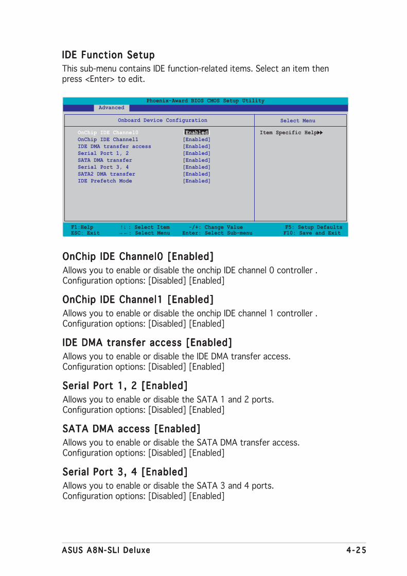
ASUS A8N-SL I De luxeASUS A8N-SL I De luxeASUS A8N-SL I De luxeASUS A8N-SL I De luxeASUS A8N-SL I De luxe 4 -254 -254 -254 -254 -25
F1:Help ↑↓ : Select Item -/+: Change Value F5: Setup DefaultsESC: Exit →←: Select Menu Enter: Select Sub-menu F10: Save and Exit
Select Menu
Item Specific Help
Phoenix-Award BIOS CMOS Setup Utility Advanced
IDE Function SetupIDE Function SetupIDE Function SetupIDE Function SetupIDE Function Setup
This sub-menu contains IDE function-related items. Select an item thenpress <Enter> to edit.
Onboard Device Configuration
OnChip IDE Channel0 [Enabled]OnChip IDE Channel1 [Enabled]IDE DMA transfer access [Enabled]Serial Port 1, 2 [Enabled]SATA DMA transfer [Enabled]Serial Port 3, 4 [Enabled]SATA2 DMA transfer [Enabled]IDE Prefetch Mode [Enabled]
OnChip IDE Channel0 [Enabled]OnChip IDE Channel0 [Enabled]OnChip IDE Channel0 [Enabled]OnChip IDE Channel0 [Enabled]OnChip IDE Channel0 [Enabled]
Allows you to enable or disable the onchip IDE channel 0 controller .Configuration options: [Disabled] [Enabled]
OnChip IDE Channel1 [Enabled]OnChip IDE Channel1 [Enabled]OnChip IDE Channel1 [Enabled]OnChip IDE Channel1 [Enabled]OnChip IDE Channel1 [Enabled]
Allows you to enable or disable the onchip IDE channel 1 controller .Configuration options: [Disabled] [Enabled]
IDE DMA transfer access [Enabled]IDE DMA transfer access [Enabled]IDE DMA transfer access [Enabled]IDE DMA transfer access [Enabled]IDE DMA transfer access [Enabled]
Allows you to enable or disable the IDE DMA transfer access.Configuration options: [Disabled] [Enabled]
Serial Port 1, 2 [Enabled]Serial Port 1, 2 [Enabled]Serial Port 1, 2 [Enabled]Serial Port 1, 2 [Enabled]Serial Port 1, 2 [Enabled]
Allows you to enable or disable the SATA 1 and 2 ports.Configuration options: [Disabled] [Enabled]
SATA DMA access [Enabled]SATA DMA access [Enabled]SATA DMA access [Enabled]SATA DMA access [Enabled]SATA DMA access [Enabled]
Allows you to enable or disable the SATA DMA transfer access.Configuration options: [Disabled] [Enabled]
Serial Port 3, 4 [Enabled]Serial Port 3, 4 [Enabled]Serial Port 3, 4 [Enabled]Serial Port 3, 4 [Enabled]Serial Port 3, 4 [Enabled]
Allows you to enable or disable the SATA 3 and 4 ports.Configuration options: [Disabled] [Enabled]
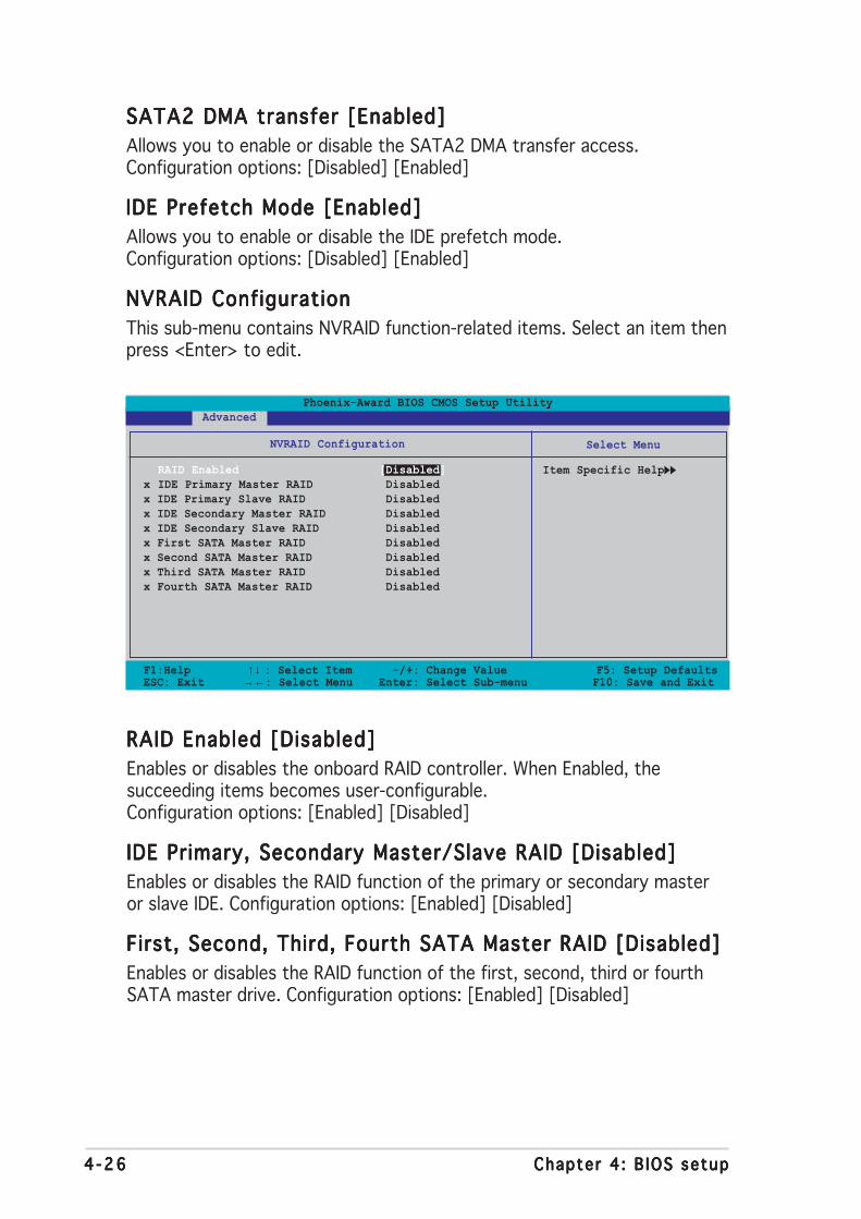
4 -264 -264 -264 -264 -26 Chapter 4 : B IOS setupChapter 4 : B IOS setupChapter 4 : B IOS setupChapter 4 : B IOS setupChapter 4 : B IOS setup
SATA2 DMA transfer [Enabled]SATA2 DMA transfer [Enabled]SATA2 DMA transfer [Enabled]SATA2 DMA transfer [Enabled]SATA2 DMA transfer [Enabled]
Allows you to enable or disable the SATA2 DMA transfer access.Configuration options: [Disabled] [Enabled]
IDE Prefetch Mode [Enabled]IDE Prefetch Mode [Enabled]IDE Prefetch Mode [Enabled]IDE Prefetch Mode [Enabled]IDE Prefetch Mode [Enabled]
Allows you to enable or disable the IDE prefetch mode.Configuration options: [Disabled] [Enabled]
NVRAID ConfigurationNVRAID ConfigurationNVRAID ConfigurationNVRAID ConfigurationNVRAID Configuration
This sub-menu contains NVRAID function-related items. Select an item thenpress <Enter> to edit.
F1:Help ↑↓ : Select Item -/+: Change Value F5: Setup DefaultsESC: Exit →←: Select Menu Enter: Select Sub-menu F10: Save and Exit
Select Menu
Item Specific Help
Phoenix-Award BIOS CMOS Setup Utility Advanced
NVRAID Configuration
RAID Enabled [Disabled]x IDE Primary Master RAID Disabledx IDE Primary Slave RAID Disabledx IDE Secondary Master RAID Disabledx IDE Secondary Slave RAID Disabledx First SATA Master RAID Disabledx Second SATA Master RAID Disabledx Third SATA Master RAID Disabledx Fourth SATA Master RAID Disabled
RAID Enabled [Disabled]RAID Enabled [Disabled]RAID Enabled [Disabled]RAID Enabled [Disabled]RAID Enabled [Disabled]
Enables or disables the onboard RAID controller. When Enabled, thesucceeding items becomes user-configurable.Configuration options: [Enabled] [Disabled]
IDE Primary, Secondary Master/Slave RAID [Disabled]IDE Primary, Secondary Master/Slave RAID [Disabled]IDE Primary, Secondary Master/Slave RAID [Disabled]IDE Primary, Secondary Master/Slave RAID [Disabled]IDE Primary, Secondary Master/Slave RAID [Disabled]
Enables or disables the RAID function of the primary or secondary masteror slave IDE. Configuration options: [Enabled] [Disabled]
First, Second, Third, Fourth SATA Master RAID [Disabled]First, Second, Third, Fourth SATA Master RAID [Disabled]First, Second, Third, Fourth SATA Master RAID [Disabled]First, Second, Third, Fourth SATA Master RAID [Disabled]First, Second, Third, Fourth SATA Master RAID [Disabled]
Enables or disables the RAID function of the first, second, third or fourthSATA master drive. Configuration options: [Enabled] [Disabled]

ASUS A8N-SL I De luxeASUS A8N-SL I De luxeASUS A8N-SL I De luxeASUS A8N-SL I De luxeASUS A8N-SL I De luxe 4 -274 -274 -274 -274 -27
F1:Help ↑↓ : Select Item -/+: Change Value F5: Setup DefaultsESC: Exit →←: Select Menu Enter: Select Sub-menu F10: Save and Exit
Select Menu
Item Specific Help
USB Configuration
USB Controller [Enabled]USB2.0 Controller [Enabled]USB Legacy support [Enabled]
Phoenix-Award BIOS CMOS Setup Utility Advanced
USB ConfigurationUSB ConfigurationUSB ConfigurationUSB ConfigurationUSB Configuration
The items in this menu allows you to change the USB-related features.Select an item then press <Enter> to display the configuration options.
USB Controller [Enabled]USB Controller [Enabled]USB Controller [Enabled]USB Controller [Enabled]USB Controller [Enabled]
Allows you to enable or disable the onchip USB controller.Configuration options: [Disabled] [Enabled]
USB 2.0 Controller [Enabled]USB 2.0 Controller [Enabled]USB 2.0 Controller [Enabled]USB 2.0 Controller [Enabled]USB 2.0 Controller [Enabled]
Allows you to enable or disable the USB 2.0 controller.Configuration options: [Disabled] [Enabled]
USB Legacy Support [Enabled]USB Legacy Support [Enabled]USB Legacy Support [Enabled]USB Legacy Support [Enabled]USB Legacy Support [Enabled]
Allows you to enable or disable support for USB devices on legacyoperating systems (OS). Configuration options: [Disabled] [Enabled]
Onboard NV LAN [Enabled]Onboard NV LAN [Enabled]Onboard NV LAN [Enabled]Onboard NV LAN [Enabled]Onboard NV LAN [Enabled]
Enables or disables the onboard NVIDIA® Gigabit LAN controller.Configuration options: [Enabled] [Disabled]
OnBoard LAN Boot ROM [Disabled]OnBoard LAN Boot ROM [Disabled]OnBoard LAN Boot ROM [Disabled]OnBoard LAN Boot ROM [Disabled]OnBoard LAN Boot ROM [Disabled]
Allows you to enable or disable the onboard LAN boot ROM.Configuration options: [Disabled] [Enabled]
Onboard Marvell LAN [Disabled]Onboard Marvell LAN [Disabled]Onboard Marvell LAN [Disabled]Onboard Marvell LAN [Disabled]Onboard Marvell LAN [Disabled]
Enables or disables the onboard Marvell® Gigabit LAN controller.Configuration options: [Enabled] [Disabled]
4 -284 -284 -284 -284 -28 Chapter 4 : B IOS setupChapter 4 : B IOS setupChapter 4 : B IOS setupChapter 4 : B IOS setupChapter 4 : B IOS setup
OnBoard LAN2 Boot ROM [Disabled]OnBoard LAN2 Boot ROM [Disabled]OnBoard LAN2 Boot ROM [Disabled]OnBoard LAN2 Boot ROM [Disabled]OnBoard LAN2 Boot ROM [Disabled]
Allows you to enable or disable the onboard LAN 2 boot ROM. This item isuser-configurable only when the PCI Giga LAN item is Enabled.Configuration options: [Disabled] [Enabled]
AC97 Audio [Enabled]AC97 Audio [Enabled]AC97 Audio [Enabled]AC97 Audio [Enabled]AC97 Audio [Enabled]
Allows you to disable or enabled the onboard AC97 audio controller.Configuration options: [Disabled] [Enabled]
PCI IEEE 1394a [Enabled]PCI IEEE 1394a [Enabled]PCI IEEE 1394a [Enabled]PCI IEEE 1394a [Enabled]PCI IEEE 1394a [Enabled]
Allows you to disable or enabled the onboard PCI IEEE 1394 controller.Configuration options: [Disabled] [Enabled]
Sil icon SATA Controller [Enabled]Sil icon SATA Controller [Enabled]Sil icon SATA Controller [Enabled]Sil icon SATA Controller [Enabled]Sil icon SATA Controller [Enabled]
Allows you to enable or disable the onboard Silicon Image RAID controller.Configuration options: [Disabled] [Enabled]
Serial Port1 Address [3F8/IRQ4]Serial Port1 Address [3F8/IRQ4]Serial Port1 Address [3F8/IRQ4]Serial Port1 Address [3F8/IRQ4]Serial Port1 Address [3F8/IRQ4]
Allows you to select the Serial Port1 base address.Configuration options: [Disabled] [3F8/IRQ4] [3E8/IRQ4] [2E8/IRQ3]
Parallel Port Address [378/IRQ7]Parallel Port Address [378/IRQ7]Parallel Port Address [378/IRQ7]Parallel Port Address [378/IRQ7]Parallel Port Address [378/IRQ7]
Allows you to select the Parallel Port base addresses.Configuration options: [Disabled] [378/IRQ7] [278/IRQ5] [3BC/IRQ7]
Parallel Port Mode [ECP+EPP]Parallel Port Mode [ECP+EPP]Parallel Port Mode [ECP+EPP]Parallel Port Mode [ECP+EPP]Parallel Port Mode [ECP+EPP]
Allows you to select the Parallel Port mode.Configuration options: [Normal] [Bi-directional] [EPP] [ECP]
ECP Mode Use DMA [3]ECP Mode Use DMA [3]ECP Mode Use DMA [3]ECP Mode Use DMA [3]ECP Mode Use DMA [3]
Allows selection of ECP Mode. Configuration options: [1] [3]
Game Port Address [201]Game Port Address [201]Game Port Address [201]Game Port Address [201]Game Port Address [201]
Allows you to select the Game Port address or to disable the port.Configuration options: [Disabled] [201] [209]
Midi Port Address [Disabled]Midi Port Address [Disabled]Midi Port Address [Disabled]Midi Port Address [Disabled]Midi Port Address [Disabled]
Allows you to select the Game Port address or to disable the port.Configuration options: [Disabled] [330] [300]
Midi Port IRQ [10]Midi Port IRQ [10]Midi Port IRQ [10]Midi Port IRQ [10]Midi Port IRQ [10]
Allows you to set the Midi port IRQ address. Configuration options: [5] [10]

ASUS A8N-SL I De luxeASUS A8N-SL I De luxeASUS A8N-SL I De luxeASUS A8N-SL I De luxeASUS A8N-SL I De luxe 4 -294 -294 -294 -294 -29
4.4.44.4.44.4.44.4.44.4.4 JumperFree ConfigurationJumperFree ConfigurationJumperFree ConfigurationJumperFree ConfigurationJumperFree Configuration
Overclock Profi le [Auto]Overclock Profi le [Auto]Overclock Profi le [Auto]Overclock Profi le [Auto]Overclock Profi le [Auto]
Allows selection of CPU overclocking options to achieve desired CPUinternal frequency. Select either one of the preset overclockingconfiguration options:
Manua lManua lManua lManua lManua l Allows you to individually set overclockingparameters.
AutoAutoAutoAutoAuto Loads the optimal settings for the system.
StandardStandardStandardStandardStandard Loads the standard settings for the system.
AI Overc lockAI Overc lockAI Overc lockAI Overc lockAI Overc lock Loads overclocking profiles with optimalparameters for stability when overclocking.
A I N.O.S .A I N.O.S .A I N.O.S .A I N.O.S .A I N.O.S . The ASUS AI Non-delay Overclocking Systemfeature intelligently determines the systemload and automatically boost the performancefor the most demanding tasks.
F1:Help ↑↓ : Select Item -/+: Change Value F5: Setup DefaultsESC: Exit →←: Select Menu Enter: Select Sub-menu F10: Save and Exit
Select Menu
Item Specific Help
JumperFree Configuration
Overclock Profile [Auto]x Overclock Options Disablex N.O.S. Option Disablex CPU Frequency 200.00x PCI Express Clock 100Mhzx DDR Voltage Autox CPU Multiplier Autox CPU Voltage Auto
Phoenix-Award BIOS CMOS Setup Utility Advanced
4 -304 -304 -304 -304 -30 Chapter 4 : B IOS setupChapter 4 : B IOS setupChapter 4 : B IOS setupChapter 4 : B IOS setupChapter 4 : B IOS setup
The following items are user-configurable only when the OverclockProfile item is set to [Manual].
Selecting a very high CPU frequency may cause the system to becomeunstable! If this happens, revert to the default setting.
CPU Frequency [XXX] (value is auto-detected)CPU Frequency [XXX] (value is auto-detected)CPU Frequency [XXX] (value is auto-detected)CPU Frequency [XXX] (value is auto-detected)CPU Frequency [XXX] (value is auto-detected)
Indicates the frequency sent by the clock generator to the system bus andPCI bus. The bus frequency (external frequency) multiplied by the busmultiple equals the CPU speed. The value of this item is auto-detected byBIOS. The values range from 200 to 400. Refer to the following table forthe correct Front Side Bus and CPU External Frequency settings.
PCI Express Clock [100MHz]PCI Express Clock [100MHz]PCI Express Clock [100MHz]PCI Express Clock [100MHz]PCI Express Clock [100MHz]
Allows you to set the PCI Express clock. Key-in a decimal value between100-200 MHz. Configuration options: [100Mhz] [101Mhz~[145Mhz]
DDR Voltage [Auto]DDR Voltage [Auto]DDR Voltage [Auto]DDR Voltage [Auto]DDR Voltage [Auto]
Sets the operating DDR voltage. Configuration options: [Auto] [2.60V][2.65V] [2.70V] [2.75V] [2.80V] [2.85V] [2.90V] [2.95V] [3.00V]
CPU Multipl ier [Auto]CPU Multipl ier [Auto]CPU Multipl ier [Auto]CPU Multipl ier [Auto]CPU Multipl ier [Auto]
Sets the operating CPU multiplier. The configuration options varydepending on the type of CPU installed. Configuration options: [Auto] [x4][x4.5] [x5] [x5.5] [x6] [x6.5] [x7] [x7.5] [x7.5] [x8] [x8.5] [x9] [x9.5][x10] [x10.5] [x11] [x11.5] [x12] [x12.5] [x13] [x13.5] [x14] [x14.5][x15] [x15.5] [x16] [x16.5] [x17] [x17.5] [x18] [x18.5] [x19] [x19.5][x20]
CPU Voltage [Auto]CPU Voltage [Auto]CPU Voltage [Auto]CPU Voltage [Auto]CPU Voltage [Auto]
Sets the operating CPU voltage. Configuration options: [Auto][1.650V] [1.6375V] [1.625V] [1.6125V] [1.600V] [1.5875V][1.575V] [1.5625V] [1.550V] [1.5375V] [1.525V] [1.5125V][1.500V] [1.4875V] [1.475V] [1.4625V] [1.450V] [1.4375V][1.425V] [1.4125V] [1.400V] [1.3875V] [1.375V] [1.3625V][1.350V] [1.3375V] [1.325V] [1.3125V] [1.300V] [1.2875V][1.275V] [1.2625V] [1.250V] [1.2375V] [1.225V] [1.2125V][1.200V] [1.1875V] [1.175V] [1.1625V] [1.150V] [1.1375V][1.125V] [1.1125V] [1.100V] [1.0875V] [1.075V] [1.0625V][1.050V] [1.0375V] [1.025V] [1.0125V] [1.000V] [0.9875V][0.975V] [0.9625V] [0.950V] [0.9375V] [0.925V] [0.9125V][0.900V] [0.8875V] [0.875V] [0.8625V] [0.850V] [0.8375V][0.825V] [0.8125V] [0.800V]
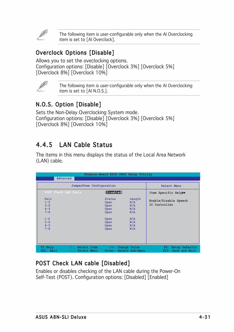
ASUS A8N-SL I De luxeASUS A8N-SL I De luxeASUS A8N-SL I De luxeASUS A8N-SL I De luxeASUS A8N-SL I De luxe 4 -314 -314 -314 -314 -31
The following item is user-configurable only when the AI Overclockingitem is set to [AI Overclock].
The following item is user-configurable only when the AI Overclockingitem is set to [AI N.O.S.].
N.O.S. Option [Disable]N.O.S. Option [Disable]N.O.S. Option [Disable]N.O.S. Option [Disable]N.O.S. Option [Disable]
Sets the Non-Delay Overclocking System mode.Configuration options: [Disable] [Overclock 3%] [Overclock 5%][Overclock 8%] [Overclock 10%]
Overclock Options [Disable]Overclock Options [Disable]Overclock Options [Disable]Overclock Options [Disable]Overclock Options [Disable]
Allows you to set the oveclocking options.Configuration options: [Disable] [Overclock 3%] [Overclock 5%][Overclock 8%] [Overclock 10%]
POST Check LAN cable [Disabled]POST Check LAN cable [Disabled]POST Check LAN cable [Disabled]POST Check LAN cable [Disabled]POST Check LAN cable [Disabled]
Enables or disables checking of the LAN cable during the Power-OnSelf-Test (POST). Configuration options: [Disabled] [Enabled]
4.4.54.4.54.4.54.4.54.4.5 LAN Cable StatusLAN Cable StatusLAN Cable StatusLAN Cable StatusLAN Cable Status
The items in this menu displays the status of the Local Area Network(LAN) cable.
F1:Help ↑↓ : Select Item -/+: Change Value F5: Setup DefaultsESC: Exit →←: Select Menu Enter: Select Sub-menu F10: Save and Exit
Select Menu
Item Specific Help
Enable/Disable SpeechIC Controller
JumperFree Configuration
POST Check LAN Cable [Disabled]
Pair Status Length1-2 Open N/A3-6 Open N/A4-5 Open N/A7-8 Open N/A
1-2 Open N/A3-6 Open N/A4-5 Open N/A7-8 Open N/A
Phoenix-Award BIOS CMOS Setup Utility Advanced
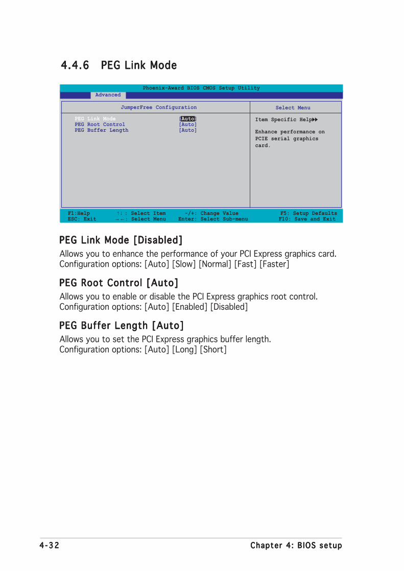
4 -324 -324 -324 -324 -32 Chapter 4 : B IOS setupChapter 4 : B IOS setupChapter 4 : B IOS setupChapter 4 : B IOS setupChapter 4 : B IOS setup
4.4.64.4.64.4.64.4.64.4.6 PEG Link ModePEG Link ModePEG Link ModePEG Link ModePEG Link Mode
F1:Help ↑↓ : Select Item -/+: Change Value F5: Setup DefaultsESC: Exit →←: Select Menu Enter: Select Sub-menu F10: Save and Exit
Select Menu
Item Specific Help
Enhance performance onPCIE serial graphicscard.
JumperFree Configuration
PEG Link Mode [Auto]PEG Root Control [Auto]PEG Buffer Length [Auto]
Phoenix-Award BIOS CMOS Setup Utility Advanced
PEG Link Mode [Disabled]PEG Link Mode [Disabled]PEG Link Mode [Disabled]PEG Link Mode [Disabled]PEG Link Mode [Disabled]
Allows you to enhance the performance of your PCI Express graphics card.Configuration options: [Auto] [Slow] [Normal] [Fast] [Faster]
PEG Root Control [Auto]PEG Root Control [Auto]PEG Root Control [Auto]PEG Root Control [Auto]PEG Root Control [Auto]
Allows you to enable or disable the PCI Express graphics root control.Configuration options: [Auto] [Enabled] [Disabled]
PEG Buffer Length [Auto]PEG Buffer Length [Auto]PEG Buffer Length [Auto]PEG Buffer Length [Auto]PEG Buffer Length [Auto]
Allows you to set the PCI Express graphics buffer length.Configuration options: [Auto] [Long] [Short]
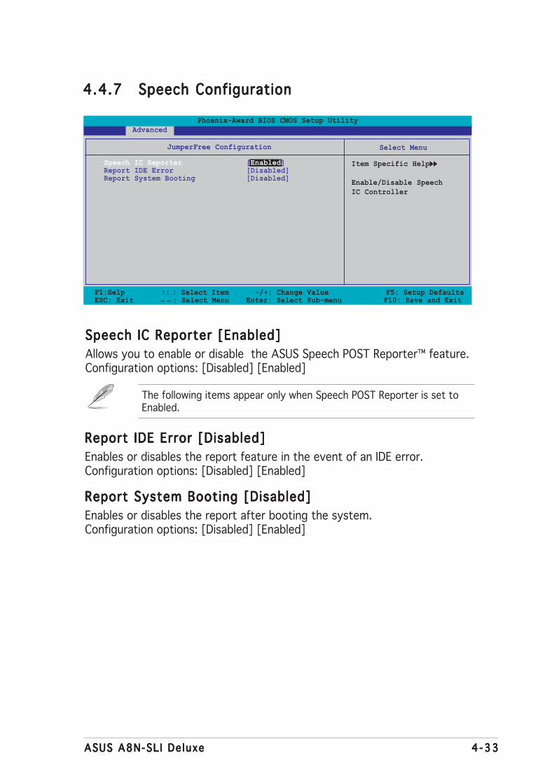
ASUS A8N-SL I De luxeASUS A8N-SL I De luxeASUS A8N-SL I De luxeASUS A8N-SL I De luxeASUS A8N-SL I De luxe 4 -334 -334 -334 -334 -33
Speech IC Reporter [Enabled]Speech IC Reporter [Enabled]Speech IC Reporter [Enabled]Speech IC Reporter [Enabled]Speech IC Reporter [Enabled]
Allows you to enable or disable the ASUS Speech POST Reporter™ feature.Configuration options: [Disabled] [Enabled]
The following items appear only when Speech POST Reporter is set toEnabled.
Report IDE Error [Disabled]Report IDE Error [Disabled]Report IDE Error [Disabled]Report IDE Error [Disabled]Report IDE Error [Disabled]
Enables or disables the report feature in the event of an IDE error.Configuration options: [Disabled] [Enabled]
Report System Booting [Disabled]Report System Booting [Disabled]Report System Booting [Disabled]Report System Booting [Disabled]Report System Booting [Disabled]
Enables or disables the report after booting the system.Configuration options: [Disabled] [Enabled]
4.4.74.4.74.4.74.4.74.4.7 Speech ConfigurationSpeech ConfigurationSpeech ConfigurationSpeech ConfigurationSpeech Configuration
F1:Help ↑↓ : Select Item -/+: Change Value F5: Setup DefaultsESC: Exit →←: Select Menu Enter: Select Sub-menu F10: Save and Exit
Select Menu
Item Specific Help
Enable/Disable SpeechIC Controller
JumperFree Configuration
Speech IC Reporter [Enabled]Report IDE Error [Disabled]Report System Booting [Disabled]
Phoenix-Award BIOS CMOS Setup Utility Advanced

4 -344 -344 -344 -344 -34 Chapter 4 : B IOS setupChapter 4 : B IOS setupChapter 4 : B IOS setupChapter 4 : B IOS setupChapter 4 : B IOS setup
Instant Music [Disabled]Instant Music [Disabled]Instant Music [Disabled]Instant Music [Disabled]Instant Music [Disabled]
Allows you to enable or disable the ASUS Instant Music feature.Configuration options: [Disabled] [Enabled]
Instant Music CD-ROM Drive [Primary Master]Instant Music CD-ROM Drive [Primary Master]Instant Music CD-ROM Drive [Primary Master]Instant Music CD-ROM Drive [Primary Master]Instant Music CD-ROM Drive [Primary Master]
Allows you to select the CD-ROM drive that you wish to use for the InstantMusic CD playback. Configuration options: [Primary Master] [Primary Slave][Secondary Master] [Secondary Slave]
4.4.84.4.84.4.84.4.84.4.8 Instant MusicInstant MusicInstant MusicInstant MusicInstant Music
F1:Help ↑↓ : Select Item -/+: Change Value F5: Setup DefaultsESC: Exit →←: Select Menu Enter: Select Sub-menu F10: Save and Exit
Select Menu
Item Specific Help
If enabled, power upby PS/2 keyboardfunction will bedisabled.
JumperFree Configuration
Instant Music [Disabled]x Instant Music CD-ROM Drive Primary Master
Phoenix-Award BIOS CMOS Setup Utility Advanced
Enabling Instant Music automatically disables the PS/2 keyboard powerup feature.
4.4.94.4.94.4.94.4.94.4.9 SLI modeSLI modeSLI modeSLI modeSLI mode
Allows you to select the Scalable Link Interface (SLI™) mode. When set toAuto, the BIOS detects the setting of the SLI EZ Selector card. Set toNormal when using one PCI Express graphics card or set to SLI mode whenusing two SLI-ready graphics cards.Configuration options: [Auto] [Normal] [SLI]
• We recommend to keep the setting of this item to [Auto].
• When not set to [Auto], make sure that the setting is the same asthe ASUS EZ selector card setting.
• See section “6.2.1 Setting the SLI selector card” on page 6-2 fordetails.
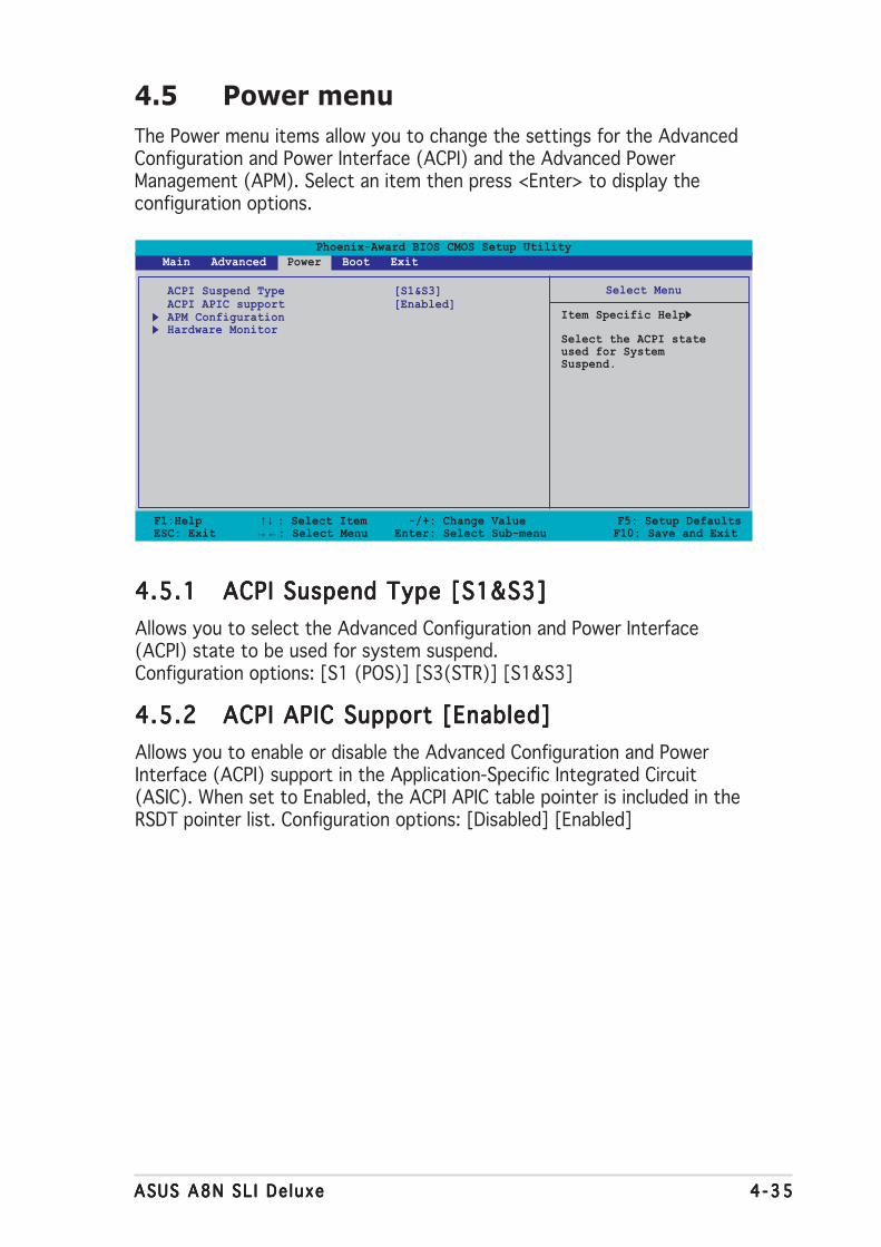
ASUS A8N SL I De luxeASUS A8N SL I De luxeASUS A8N SL I De luxeASUS A8N SL I De luxeASUS A8N SL I De luxe 4 -354 -354 -354 -354 -35
4.5 Power menu
The Power menu items allow you to change the settings for the AdvancedConfiguration and Power Interface (ACPI) and the Advanced PowerManagement (APM). Select an item then press <Enter> to display theconfiguration options.
Phoenix-Award BIOS CMOS Setup Utility Main Advanced Power Boot Exit
Select Menu
Item Specific Help
Select the ACPI stateused for SystemSuspend.
ACPI Suspend Type [S1&S3]ACPI APIC support [Enabled]APM ConfigurationHardware Monitor
F1:Help ↑↓ : Select Item -/+: Change Value F5: Setup DefaultsESC: Exit →←: Select Menu Enter: Select Sub-menu F10: Save and Exit
4.5.14.5.14.5.14.5.14.5.1 ACPI Suspend Type [S1&S3]ACPI Suspend Type [S1&S3]ACPI Suspend Type [S1&S3]ACPI Suspend Type [S1&S3]ACPI Suspend Type [S1&S3]
Allows you to select the Advanced Configuration and Power Interface(ACPI) state to be used for system suspend.Configuration options: [S1 (POS)] [S3(STR)] [S1&S3]
4.5.24.5.24.5.24.5.24.5.2 ACPI APIC Support [Enabled]ACPI APIC Support [Enabled]ACPI APIC Support [Enabled]ACPI APIC Support [Enabled]ACPI APIC Support [Enabled]
Allows you to enable or disable the Advanced Configuration and PowerInterface (ACPI) support in the Application-Specific Integrated Circuit(ASIC). When set to Enabled, the ACPI APIC table pointer is included in theRSDT pointer list. Configuration options: [Disabled] [Enabled]
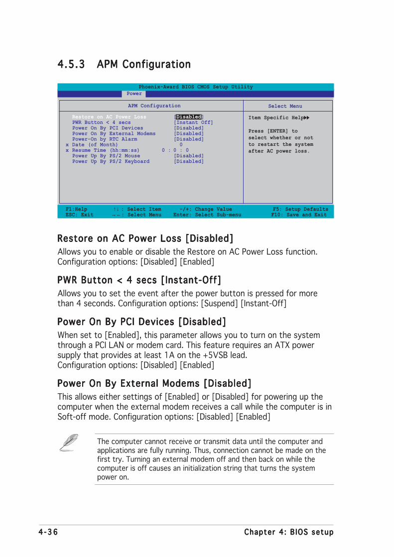
4 -364 -364 -364 -364 -36 Chapter 4 : B IOS setupChapter 4 : B IOS setupChapter 4 : B IOS setupChapter 4 : B IOS setupChapter 4 : B IOS setup
4.5.34.5.34.5.34.5.34.5.3 APM ConfigurationAPM ConfigurationAPM ConfigurationAPM ConfigurationAPM Configuration
F1:Help ↑↓ : Select Item -/+: Change Value F5: Setup DefaultsESC: Exit →←: Select Menu Enter: Select Sub-menu F10: Save and Exit
Select Menu
Item Specific Help
Press [ENTER] toselect whether or notto restart the systemafter AC power loss.
APM Configuration
Restore on AC Power Loss [Disabled]PWR Button < 4 secs [Instant Off]Power On By PCI Devices [Disabled]Power On By External Modems [Disabled]Power-On by RTC Alarm [Disabled]
x Date (of Month) 0x Resume Time (hh:mm:ss) 0 : 0 : 0
Power Up By PS/2 Mouse [Disabled]Power Up By PS/2 Keyboard [Disabled]
Phoenix-Award BIOS CMOS Setup Utility Power
Restore on AC Power Loss [Disabled]Restore on AC Power Loss [Disabled]Restore on AC Power Loss [Disabled]Restore on AC Power Loss [Disabled]Restore on AC Power Loss [Disabled]
Allows you to enable or disable the Restore on AC Power Loss function.Configuration options: [Disabled] [Enabled]
PWR Button < 4 secs [Instant-Off]PWR Button < 4 secs [Instant-Off]PWR Button < 4 secs [Instant-Off]PWR Button < 4 secs [Instant-Off]PWR Button < 4 secs [Instant-Off]
Allows you to set the event after the power button is pressed for morethan 4 seconds. Configuration options: [Suspend] [Instant-Off]
Power On By PCI Devices [Disabled]Power On By PCI Devices [Disabled]Power On By PCI Devices [Disabled]Power On By PCI Devices [Disabled]Power On By PCI Devices [Disabled]
When set to [Enabled], this parameter allows you to turn on the systemthrough a PCI LAN or modem card. This feature requires an ATX powersupply that provides at least 1A on the +5VSB lead.Configuration options: [Disabled] [Enabled]
Power On By External Modems [Disabled]Power On By External Modems [Disabled]Power On By External Modems [Disabled]Power On By External Modems [Disabled]Power On By External Modems [Disabled]
This allows either settings of [Enabled] or [Disabled] for powering up thecomputer when the external modem receives a call while the computer is inSoft-off mode. Configuration options: [Disabled] [Enabled]
The computer cannot receive or transmit data until the computer andapplications are fully running. Thus, connection cannot be made on thefirst try. Turning an external modem off and then back on while thecomputer is off causes an initialization string that turns the systempower on.
ASUS A8N SL I De luxeASUS A8N SL I De luxeASUS A8N SL I De luxeASUS A8N SL I De luxeASUS A8N SL I De luxe 4 -374 -374 -374 -374 -37
Power On By RTC Alarm [Disabled]Power On By RTC Alarm [Disabled]Power On By RTC Alarm [Disabled]Power On By RTC Alarm [Disabled]Power On By RTC Alarm [Disabled]
Allows you to enable or disable RTC to generate a wake event. When thisitem is set to Enabled, the items Date of Month Alarm and Time (hh:mm:ss)Alarm items become user-configurable with set values.Configuration options: [Disabled] [Enabled]
Day of Month Alarm [Disabled]Day of Month Alarm [Disabled]Day of Month Alarm [Disabled]Day of Month Alarm [Disabled]Day of Month Alarm [Disabled]
To set the date of alarm, highlight this item and press <Enter> to displaythe Day of Month Alarm pop-up menu. Key-in a value within the specifiedrange then press <Enter>. Configuration options: [Min=0] [Max=31]
Time (hh:mm:ss) Alarm [Disabled]Time (hh:mm:ss) Alarm [Disabled]Time (hh:mm:ss) Alarm [Disabled]Time (hh:mm:ss) Alarm [Disabled]Time (hh:mm:ss) Alarm [Disabled]
To set the time of alarm:
1. Highlight this item and press <Enter> to display a pop-up menu for thehour field.
2. Key-in a value (Min=0, Max=23), then press <Enter>.
3. Press <TAB> to move to the minutes field then press <Enter>.
4. Key-in a minute value (Min=0, Max=59), then press <Enter>.
5. Press <TAB> to move to the seconds field then press <Enter>.
6. Key-in a value (Min=0, Max=59), then press <Enter>.
Power Up By PS/2 Mouse [Disabled]Power Up By PS/2 Mouse [Disabled]Power Up By PS/2 Mouse [Disabled]Power Up By PS/2 Mouse [Disabled]Power Up By PS/2 Mouse [Disabled]
When set to [Enabled], this parameter allows you to use the PS/2 mouseto turn on the system. This feature requires an ATX power supply thatprovides at least 1A on the +5VSB lead.Configuration options: [Disabled] [Enabled]
Power On By PS/2 Keyboard [Disabled]Power On By PS/2 Keyboard [Disabled]Power On By PS/2 Keyboard [Disabled]Power On By PS/2 Keyboard [Disabled]Power On By PS/2 Keyboard [Disabled]
Allows you to disable the Power On by PS/2 keyboard function or setspecific keys on the PS/2 keyboard to turn on the system. This featurerequires an ATX power supply that provides at least 1A on the +5VSB lead.Configuration options: [Disabled] [Space Bar] [Ctrl-ESC] [Power Key]

4 -384 -384 -384 -384 -38 Chapter 4 : B IOS setupChapter 4 : B IOS setupChapter 4 : B IOS setupChapter 4 : B IOS setupChapter 4 : B IOS setup
4.5.44.5.44.5.44.5.44.5.4 Hardware MonitorHardware MonitorHardware MonitorHardware MonitorHardware Monitor
The items in this sub-menu displays the hardware monitor valuesautomatically detected by the BIOS. It also allows you to change CPU Q-Fanfeature-related parameters. Select an item then press <Enter> to displaythe configuration options.
F1:Help ↑↓ : Select Item -/+: Change Value F5: Setup DefaultsESC: Exit →←: Select Menu Enter: Select Sub-menu F10: Save and Exit
Select Menu
Item Specific Help
Press [Enter] toenable or disable
Hardware Monitor
Q-Fan Controller [Disabled]Vcore Voltage 1.50V3.3V Voltage 3.31V5V Voltage 4.94V12V Voltage 11.26V
CPU Temperature 48ºCM/B Temperature 38ºCCPU FAN Speed 4962 RPMCHA1 FAN Speed 0 RPMCHIP FAN Speed 5443 RPM
x Q-Fan1 Stop Temperature 20ºCx Q-Fan1 StartUp Temperature 25ºCx Q-Fan1 Full Speed Temperature 72ºC
Phoenix-Award BIOS CMOS Setup Utility Power
Q-Fan Controller [Disabled]Q-Fan Controller [Disabled]Q-Fan Controller [Disabled]Q-Fan Controller [Disabled]Q-Fan Controller [Disabled]
Allows you to enable or disable the Q-Fan controller.Configuration options: [Disabled] [Enabled]
VCORE Voltage, +12V Voltage, 3.3V Voltage, 5VCCVCORE Voltage, +12V Voltage, 3.3V Voltage, 5VCCVCORE Voltage, +12V Voltage, 3.3V Voltage, 5VCCVCORE Voltage, +12V Voltage, 3.3V Voltage, 5VCCVCORE Voltage, +12V Voltage, 3.3V Voltage, 5VCCVoltageVoltageVoltageVoltageVoltage
The onboard hardware monitor automatically detects the voltage outputthrough the onboard voltage regulators. These items are notuser-configurable.
CPU Temperature, M/B TemperatureCPU Temperature, M/B TemperatureCPU Temperature, M/B TemperatureCPU Temperature, M/B TemperatureCPU Temperature, M/B Temperature
The onboard hardware monitor automatically detects and displays themotherboard and CPU temperatures. These items are not user-configurable.
CPU Fan SpeedCPU Fan SpeedCPU Fan SpeedCPU Fan SpeedCPU Fan SpeedCHA1 Fan SpeedCHA1 Fan SpeedCHA1 Fan SpeedCHA1 Fan SpeedCHA1 Fan SpeedCHIP Fan SpeedCHIP Fan SpeedCHIP Fan SpeedCHIP Fan SpeedCHIP Fan Speed
The onboard hardware monitor automatically detects and displays theChassis, CPU, and Chip fan speeds in rotations per minute (RPM). If the fanis not connected to the motherboard, the field shows 0. These items arenot user-configurable.
ASUS A8N SL I De luxeASUS A8N SL I De luxeASUS A8N SL I De luxeASUS A8N SL I De luxeASUS A8N SL I De luxe 4 -394 -394 -394 -394 -39
Q-Fan1 Stop TemperatureQ-Fan1 Stop TemperatureQ-Fan1 Stop TemperatureQ-Fan1 Stop TemperatureQ-Fan1 Stop Temperature
Allows you to set the temperature threshold before the CPU fan stops.Configuration options: [16ºC] [18ºC] [20ºC] [22ºC]
Q-Fan1 Start TemperatureQ-Fan1 Start TemperatureQ-Fan1 Start TemperatureQ-Fan1 Start TemperatureQ-Fan1 Start Temperature
Allows you to set the temperature that when detected starts the CPU fan.Configuration options: [23ºC] [25ºC] [27ºC] [29ºC]
Q-Fan1 Full Speed TemperatureQ-Fan1 Full Speed TemperatureQ-Fan1 Full Speed TemperatureQ-Fan1 Full Speed TemperatureQ-Fan1 Full Speed Temperature
Allows you to set the temperature threshold before the CPU fan rotates atfull speed. Configuration options: [51ºC] [54ºC] [57ºC] [60ºC] [63ºC][66ºC] [69ºC] [72ºC] [75ºC] [78ºC] [81ºC]

4 -404 -404 -404 -404 -40 Chapter 4 : B IOS setupChapter 4 : B IOS setupChapter 4 : B IOS setupChapter 4 : B IOS setupChapter 4 : B IOS setup
4.6 Boot menu
The Boot menu items allow you to change the system boot options. Selectan item then press <Enter> to display the sub-menu.
Phoenix-Award BIOS CMOS Setup Utility Main Advanced Power Boot Exit
Select Menu
Item Specific Help
Boot Device PriorityRemovable DrivesHard Disk DrivesCDROM DrivesBoot Settings ConfigurationSecurity
F1:Help ↑↓ : Select Item -/+: Change Value F5: Setup DefaultsESC: Exit →←: Select Menu Enter: Select Sub-menu F10: Save and Exit
4.6.14.6.14.6.14.6.14.6.1 Boot Device PriorityBoot Device PriorityBoot Device PriorityBoot Device PriorityBoot Device Priority
1st ~ xxth Boot Device [Removable]1st ~ xxth Boot Device [Removable]1st ~ xxth Boot Device [Removable]1st ~ xxth Boot Device [Removable]1st ~ xxth Boot Device [Removable]
These items specify the boot device priority sequence from the availabledevices. The number of device items that appears on the screen dependson the number of devices installed in the system.Configuration options: [Removable] [Hard Disk] [CDROM] [Legacy LAN][Disabled]
F1:Help ↑↓ : Select Item -/+: Change Value F5: Setup DefaultsESC: Exit →←: Select Menu Enter: Select Sub-menu F10: Save and Exit
Select Menu
Item Specific Help
Select your bootdevice priority
Boot Device Priority
1st Boot Device [Removable]2nd Boot Device [Hard Disk]3rd Boot Device [CDROM]4th Boot Device [Disabled]
Phoenix-Award BIOS CMOS Setup Utility Power

ASUS A8N SL I De luxeASUS A8N SL I De luxeASUS A8N SL I De luxeASUS A8N SL I De luxeASUS A8N SL I De luxe 4 -414 -414 -414 -414 -41
4.6.24.6.24.6.24.6.24.6.2 Removable DrivesRemovable DrivesRemovable DrivesRemovable DrivesRemovable Drives
1. Floppy Disks1. Floppy Disks1. Floppy Disks1. Floppy Disks1. Floppy Disks
Allows you to assign a removable drive attached to the system.
F1:Help ↑↓ : Select Item -/+: Change Value F5: Setup DefaultsESC: Exit →←: Select Menu Enter: Select Sub-menu F10: Save and Exit
Select Menu
Item Specific Help
Use <↑> or <↓> toselect a device, thenpress <+> to move itup, or <-> to move itdown the list. Press<ESC> to exit thismenu.
Removable Drives
1. Floppy Disks
Phoenix-Award BIOS CMOS Setup Utility Boot
4.6.34.6.34.6.34.6.34.6.3 Hard Disk DrivesHard Disk DrivesHard Disk DrivesHard Disk DrivesHard Disk Drives
1. 1st Master: XXXXXXXXX1. 1st Master: XXXXXXXXX1. 1st Master: XXXXXXXXX1. 1st Master: XXXXXXXXX1. 1st Master: XXXXXXXXX
Allows you to assign hard disk drives attached to the system.
F1:Help ↑↓ : Select Item -/+: Change Value F5: Setup DefaultsESC: Exit →←: Select Menu Enter: Select Sub-menu F10: Save and Exit
Select Menu
Item Specific Help
Use <↑> or <↓> toselect a device, thenpress <+> to move itup, or <-> to move itdown the list. Press<ESC> to exit thismenu.
Hard Disk Drives
1. 1st Master: XXXXXXXXX2. Bootable Add-in Cards
Phoenix-Award BIOS CMOS Setup Utility Boot
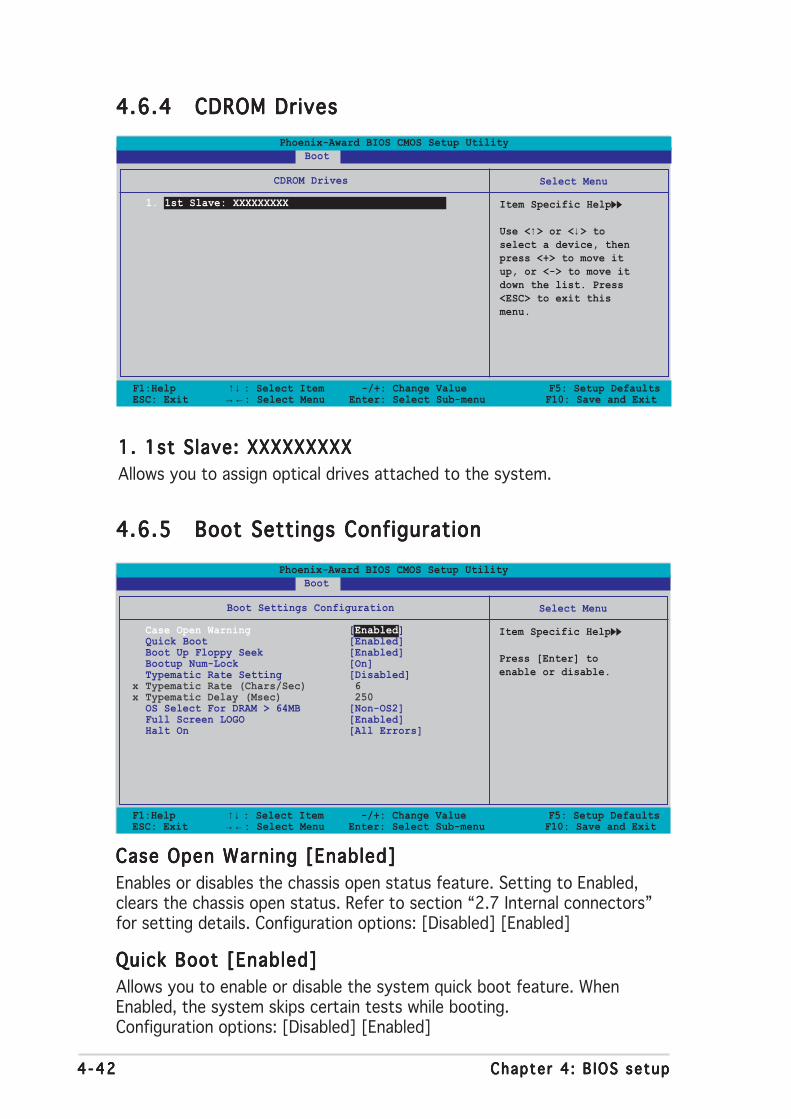
4 -424 -424 -424 -424 -42 Chapter 4 : B IOS setupChapter 4 : B IOS setupChapter 4 : B IOS setupChapter 4 : B IOS setupChapter 4 : B IOS setup
4.6.44.6.44.6.44.6.44.6.4 CDROM DrivesCDROM DrivesCDROM DrivesCDROM DrivesCDROM Drives
1. 1st Slave: XXXXXXXXX1. 1st Slave: XXXXXXXXX1. 1st Slave: XXXXXXXXX1. 1st Slave: XXXXXXXXX1. 1st Slave: XXXXXXXXX
Allows you to assign optical drives attached to the system.
F1:Help ↑↓ : Select Item -/+: Change Value F5: Setup DefaultsESC: Exit →←: Select Menu Enter: Select Sub-menu F10: Save and Exit
Select Menu
Item Specific Help
Use <↑> or <↓> toselect a device, thenpress <+> to move itup, or <-> to move itdown the list. Press<ESC> to exit thismenu.
CDROM Drives
1. 1st Slave: XXXXXXXXX
Phoenix-Award BIOS CMOS Setup Utility Boot
4.6.54.6.54.6.54.6.54.6.5 Boot Settings ConfigurationBoot Settings ConfigurationBoot Settings ConfigurationBoot Settings ConfigurationBoot Settings Configuration
F1:Help ↑↓ : Select Item -/+: Change Value F5: Setup DefaultsESC: Exit →←: Select Menu Enter: Select Sub-menu F10: Save and Exit
Select Menu
Item Specific Help
Press [Enter] toenable or disable.
Boot Settings Configuration
Case Open Warning [Enabled]Quick Boot [Enabled]Boot Up Floppy Seek [Enabled]Bootup Num-Lock [On]Typematic Rate Setting [Disabled]
x Typematic Rate (Chars/Sec) 6x Typematic Delay (Msec) 250
OS Select For DRAM > 64MB [Non-OS2]Full Screen LOGO [Enabled]Halt On [All Errors]
Phoenix-Award BIOS CMOS Setup Utility Boot
Case Open Warning [Enabled]Case Open Warning [Enabled]Case Open Warning [Enabled]Case Open Warning [Enabled]Case Open Warning [Enabled]
Enables or disables the chassis open status feature. Setting to Enabled,clears the chassis open status. Refer to section “2.7 Internal connectors”for setting details. Configuration options: [Disabled] [Enabled]
Quick Boot [Enabled]Quick Boot [Enabled]Quick Boot [Enabled]Quick Boot [Enabled]Quick Boot [Enabled]
Allows you to enable or disable the system quick boot feature. WhenEnabled, the system skips certain tests while booting.Configuration options: [Disabled] [Enabled]
ASUS A8N SL I De luxeASUS A8N SL I De luxeASUS A8N SL I De luxeASUS A8N SL I De luxeASUS A8N SL I De luxe 4 -434 -434 -434 -434 -43
The items Typemat ic Rate (Chars/Sec)Typemat ic Rate (Chars/Sec)Typemat ic Rate (Chars/Sec)Typemat ic Rate (Chars/Sec)Typemat ic Rate (Chars/Sec) and Typemat ic De layTypemat ic De layTypemat ic De layTypemat ic De layTypemat ic De lay(Msec)(Msec)(Msec)(Msec)(Msec) becomes user-configurable only when the item Typematic RateSetting is enabled.
Boot Up Floppy Seek [Enabled]Boot Up Floppy Seek [Enabled]Boot Up Floppy Seek [Enabled]Boot Up Floppy Seek [Enabled]Boot Up Floppy Seek [Enabled]
Enables or disables the chassis open status feature. Setting to Enabled,clears the chassis open status. Configuration options: [Disabled] [Enabled]
Bootup Num-Lock [On]Bootup Num-Lock [On]Bootup Num-Lock [On]Bootup Num-Lock [On]Bootup Num-Lock [On]
Allows you to select the power-on state for the NumLock.Configuration options: [Off] [On]
Typematic Rate Setting [Disabled]Typematic Rate Setting [Disabled]Typematic Rate Setting [Disabled]Typematic Rate Setting [Disabled]Typematic Rate Setting [Disabled]
Allows you to set the keystroke rate. Enable this item to configure theTypematic Rate (Chars/Sec) Typematic Rate (Chars/Sec) Typematic Rate (Chars/Sec) Typematic Rate (Chars/Sec) Typematic Rate (Chars/Sec) and the Typematic Delay (Msec)Typematic Delay (Msec)Typematic Delay (Msec)Typematic Delay (Msec)Typematic Delay (Msec).Configuration options: [Disabled] [Enabled]
Typematic Rate (Chars/Sec) [6]Typematic Rate (Chars/Sec) [6]Typematic Rate (Chars/Sec) [6]Typematic Rate (Chars/Sec) [6]Typematic Rate (Chars/Sec) [6]
Allows you to select the rate at which a character repeats when you hold akey. Configuration options: [6] [8] [10] [12] [15] [20] [24] [30]
Typematic Delay (Msec) [250]Typematic Delay (Msec) [250]Typematic Delay (Msec) [250]Typematic Delay (Msec) [250]Typematic Delay (Msec) [250]
Allows you to set the delay before keystrokes begin to repeat.Configuration options: [250] [500] [750] [1000]
OS Select for DRAM > 64MB [Non-OS2]OS Select for DRAM > 64MB [Non-OS2]OS Select for DRAM > 64MB [Non-OS2]OS Select for DRAM > 64MB [Non-OS2]OS Select for DRAM > 64MB [Non-OS2]
Set this item to OS2 only when you are running on an OS/2 operatingsystem with an installed RAM of greater than 64 KB.Configuration options: [Non-OS2] [OS2]
Full Screen LOGO [Enabled]Full Screen LOGO [Enabled]Full Screen LOGO [Enabled]Full Screen LOGO [Enabled]Full Screen LOGO [Enabled]
Allows you to enable or disable the full screen logo display feature.Configuration options: [Disabled] [Enabled]
• Make sure that the above item is set to [Enabled] if you want to usethe ASUS MyLogo2™ feature.
• See section “5.4.1 ASUS MyLogo2™” for details.
Halt On [All Errors]Halt On [All Errors]Halt On [All Errors]Halt On [All Errors]Halt On [All Errors]
Allows you to error report type.Configuration options: [All Errors] [No Errors] [All, But Keyboard][All, But Diskette] [All, But Disk/Key]
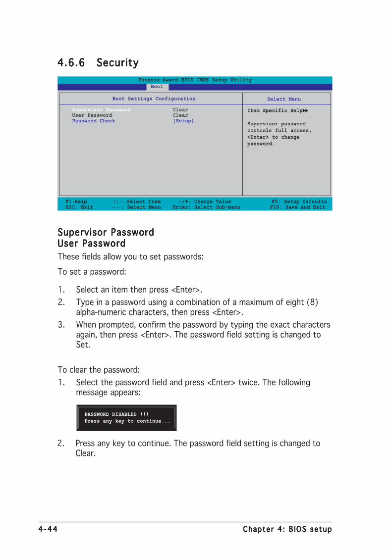
4 -444 -444 -444 -444 -44 Chapter 4 : B IOS setupChapter 4 : B IOS setupChapter 4 : B IOS setupChapter 4 : B IOS setupChapter 4 : B IOS setup
4.6.64.6.64.6.64.6.64.6.6 SecuritySecuritySecuritySecuritySecurity
F1:Help ↑↓ : Select Item -/+: Change Value F5: Setup DefaultsESC: Exit →←: Select Menu Enter: Select Sub-menu F10: Save and Exit
Select Menu
Item Specific Help
Supervisor passwordcontrols full access,<Enter> to changepassword.
Boot Settings Configuration
Supervisor Password ClearUser Password ClearPassword Check [Setup]
Phoenix-Award BIOS CMOS Setup Utility Boot
Supervisor PasswordSupervisor PasswordSupervisor PasswordSupervisor PasswordSupervisor PasswordUser PasswordUser PasswordUser PasswordUser PasswordUser Password
These fields allow you to set passwords:
To set a password:
1. Select an item then press <Enter>.
2. Type in a password using a combination of a maximum of eight (8)alpha-numeric characters, then press <Enter>.
3. When prompted, confirm the password by typing the exact charactersagain, then press <Enter>. The password field setting is changed toSet.
To clear the password:
1. Select the password field and press <Enter> twice. The followingmessage appears:
PASSWORD DISABLED !!!Press any key to continue...
2. Press any key to continue. The password field setting is changed toClear.

ASUS A8N SL I De luxeASUS A8N SL I De luxeASUS A8N SL I De luxeASUS A8N SL I De luxeASUS A8N SL I De luxe 4 -454 -454 -454 -454 -45
A note about passwordsA note about passwordsA note about passwordsA note about passwordsA note about passwords
The Supervisor password is required to enter the BIOS Setup programpreventing unauthorized access. The User password is required toboot the system preventing unauthorized use.
Forgot your password?Forgot your password?Forgot your password?Forgot your password?Forgot your password?
If you forget your password, you can clear it by erasing the CMOS RealTime Clock (RTC) RAM. The RAM data containing the passwordinformation is powered by the onboard button cell battery. If you needto erase the CMOS RAM, refer to section “2.6 Jumpers” forinstructions.
Password CheckPassword CheckPassword CheckPassword CheckPassword Check
This field requires you to enter the password before entering the BIOSsetup or the system. Select [Setup] to require the password beforeentering the BIOS Setup. Select [System] to require the password beforeentering the system. Configuration options: [Setup] [System]
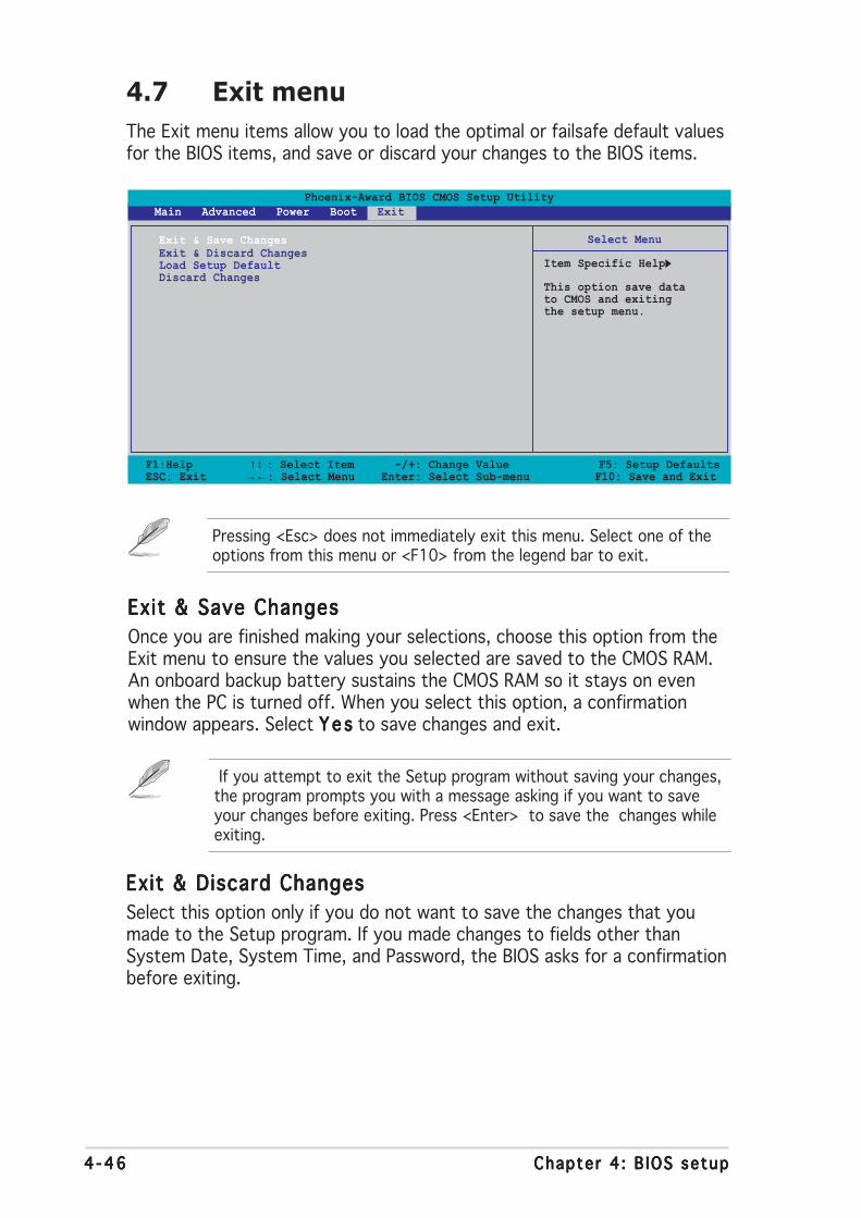
4 -464 -464 -464 -464 -46 Chapter 4 : B IOS setupChapter 4 : B IOS setupChapter 4 : B IOS setupChapter 4 : B IOS setupChapter 4 : B IOS setup
Phoenix-Award BIOS CMOS Setup Utility Main Advanced Power Boot Exit
Select Menu
Item Specific Help
This option save datato CMOS and exitingthe setup menu.
Exit & Save ChangesExit & Discard ChangesLoad Setup DefaultDiscard Changes
F1:Help ↑↓ : Select Item -/+: Change Value F5: Setup DefaultsESC: Exit →←: Select Menu Enter: Select Sub-menu F10: Save and Exit
4.7 Exit menu
The Exit menu items allow you to load the optimal or failsafe default valuesfor the BIOS items, and save or discard your changes to the BIOS items.
Exit & Save ChangesExit & Save ChangesExit & Save ChangesExit & Save ChangesExit & Save Changes
Once you are finished making your selections, choose this option from theExit menu to ensure the values you selected are saved to the CMOS RAM.An onboard backup battery sustains the CMOS RAM so it stays on evenwhen the PC is turned off. When you select this option, a confirmationwindow appears. Select Y e sY e sY e sY e sY e s to save changes and exit.
Pressing <Esc> does not immediately exit this menu. Select one of theoptions from this menu or <F10> from the legend bar to exit.
Exit & Discard ChangesExit & Discard ChangesExit & Discard ChangesExit & Discard ChangesExit & Discard Changes
Select this option only if you do not want to save the changes that youmade to the Setup program. If you made changes to fields other thanSystem Date, System Time, and Password, the BIOS asks for a confirmationbefore exiting.
If you attempt to exit the Setup program without saving your changes,the program prompts you with a message asking if you want to saveyour changes before exiting. Press <Enter> to save the changes whileexiting.

ASUS A8N SL I De luxeASUS A8N SL I De luxeASUS A8N SL I De luxeASUS A8N SL I De luxeASUS A8N SL I De luxe 4 -474 -474 -474 -474 -47
Load Setup DefaultsLoad Setup DefaultsLoad Setup DefaultsLoad Setup DefaultsLoad Setup Defaults
This option allows you to load the default values for each of theparameters on the Setup menus. When you select this option or if youpress <F5>, a confirmation window appears. Select Y e sY e sY e sY e sY e s to load defaultvalues. Select Ex it & Save ChangesEx it & Save ChangesEx it & Save ChangesEx it & Save ChangesEx it & Save Changes or make other changes beforesaving the values to the non-volatile RAM.
Discard ChangesDiscard ChangesDiscard ChangesDiscard ChangesDiscard Changes
This option allows you to discard the selections you made and restore thepreviously saved values. After selecting this option, a confirmation appears.Select Y e sY e sY e sY e sY e s to discard any changes and load the previously saved values.

4 -484 -484 -484 -484 -48 Chapter 4 : B IOS setupChapter 4 : B IOS setupChapter 4 : B IOS setupChapter 4 : B IOS setupChapter 4 : B IOS setup
5Softwaresupport
This chapter describes the contentsof the support CD that comes withthe motherboard package.

ASUS A8N-SLI DeluxeASUS A8N-SLI DeluxeASUS A8N-SLI DeluxeASUS A8N-SLI DeluxeASUS A8N-SLI Deluxe
Chapter summary
5.1 Installing an operating system ............................................. 5-1
5.2 Support CD information ........................................................ 5-1
5.4 Software information ........................................................... 5-9
5.5 RAID configurations ............................................................ 5-21
5.6 Creating a RAID driver disk ................................................. 5-40
5.7 Cool ‘n’ Quiet!™ Technology ............................................... 5-41
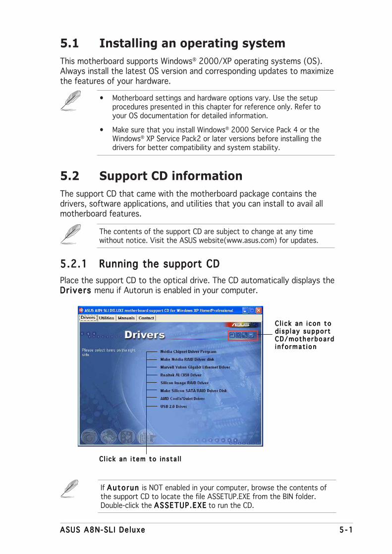
ASUS A8N-SL I De luxeASUS A8N-SL I De luxeASUS A8N-SL I De luxeASUS A8N-SL I De luxeASUS A8N-SL I De luxe 5 - 15 - 15 - 15 - 15 - 1
If Auto run Auto run Auto run Auto run Auto run is NOT enabled in your computer, browse the contents ofthe support CD to locate the file ASSETUP.EXE from the BIN folder.Double-click the ASSETUP .EXEASSETUP .EXEASSETUP .EXEASSETUP .EXEASSETUP .EXE to run the CD.
C l i c k an i t em to i n s ta l lC l i c k an i t em to i n s ta l lC l i c k an i t em to i n s ta l lC l i c k an i t em to i n s ta l lC l i c k an i t em to i n s ta l l
5.1 Installing an operating system
This motherboard supports Windows® 2000/XP operating systems (OS).Always install the latest OS version and corresponding updates to maximizethe features of your hardware.
5.2 Support CD information
The support CD that came with the motherboard package contains thedrivers, software applications, and utilities that you can install to avail allmotherboard features.
5.2.15.2.15.2.15.2.15.2.1 Running the support CDRunning the support CDRunning the support CDRunning the support CDRunning the support CD
Place the support CD to the optical drive. The CD automatically displays theDr ivers Dr ivers Dr ivers Dr ivers Dr ivers menu if Autorun is enabled in your computer.
• Motherboard settings and hardware options vary. Use the setupprocedures presented in this chapter for reference only. Refer toyour OS documentation for detailed information.
• Make sure that you install Windows® 2000 Service Pack 4 or theWindows® XP Service Pack2 or later versions before installing thedrivers for better compatibility and system stability.
The contents of the support CD are subject to change at any timewithout notice. Visit the ASUS website(www.asus.com) for updates.
C l i c k an i con toC l i c k an i con toC l i c k an i con toC l i c k an i con toC l i c k an i con tod i sp l ay suppo r td i sp l ay suppo r td i sp l ay suppo r td i sp l ay suppo r td i sp l ay suppo r tCD/mothe rboa rdCD/mothe rboa rdCD/mothe rboa rdCD/mothe rboa rdCD/mothe rboa rdi n f o rmat i oni n f o rmat i oni n f o rmat i oni n f o rmat i oni n f o rmat i on

5 - 25 - 25 - 25 - 25 - 2 Chapter 5 : Software supportChapter 5 : Software supportChapter 5 : Software supportChapter 5 : Software supportChapter 5 : Software support
5.2.25.2.25.2.25.2.25.2.2 Drivers menuDrivers menuDrivers menuDrivers menuDrivers menu
The drivers menu shows the available device drivers if the system detectsinstalled devices. Install the necessary drivers to activate the devices.
Nvidia Chipset Driver ProgramNvidia Chipset Driver ProgramNvidia Chipset Driver ProgramNvidia Chipset Driver ProgramNvidia Chipset Driver Program
Installs the NVIDIA® Chipset drivers for the NVIDIA® nForce™ 4 SLI chipset.
Make NVIDIA RAID Driver DiskMake NVIDIA RAID Driver DiskMake NVIDIA RAID Driver DiskMake NVIDIA RAID Driver DiskMake NVIDIA RAID Driver Disk
Creates the NVIDIA® driver disk for Serial ATA and RAID features.
Marvell Yukon Gigabit Ethernet DriverMarvell Yukon Gigabit Ethernet DriverMarvell Yukon Gigabit Ethernet DriverMarvell Yukon Gigabit Ethernet DriverMarvell Yukon Gigabit Ethernet Driver
Installs the Marvell® Yukon Gigabit Ethernet driver.
Realtek ALC850 DriverRealtek ALC850 DriverRealtek ALC850 DriverRealtek ALC850 DriverRealtek ALC850 Driver
Installs the Realtek® ALC850 audio controller and application.
Sil icon Image RAID DriverSil icon Image RAID DriverSil icon Image RAID DriverSil icon Image RAID DriverSil icon Image RAID Driver
Displays the README file of the Silicon Image SATA Link™ Sil 3114 driverdriver installation.
Make Sil icon SATA RAID Driver DiskMake Sil icon SATA RAID Driver DiskMake Sil icon SATA RAID Driver DiskMake Sil icon SATA RAID Driver DiskMake Sil icon SATA RAID Driver Disk
Creates the Silicon Image SATA Link™ Sil 3114 driver disk for Serial ATARAID.
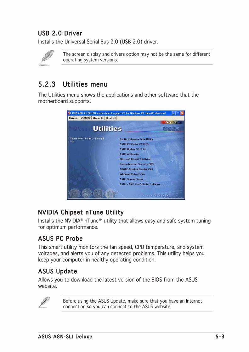
ASUS A8N-SL I De luxeASUS A8N-SL I De luxeASUS A8N-SL I De luxeASUS A8N-SL I De luxeASUS A8N-SL I De luxe 5 - 35 - 35 - 35 - 35 - 3
The screen display and drivers option may not be the same for differentoperating system versions.
USB 2.0 DriverUSB 2.0 DriverUSB 2.0 DriverUSB 2.0 DriverUSB 2.0 Driver
Installs the Universal Serial Bus 2.0 (USB 2.0) driver.
5.2.35.2.35.2.35.2.35.2.3 Utilities menuUtilities menuUtilities menuUtilities menuUtilities menu
The Utilities menu shows the applications and other software that themotherboard supports.
NVIDIA Chipset nTune Util ityNVIDIA Chipset nTune Util ityNVIDIA Chipset nTune Util ityNVIDIA Chipset nTune Util ityNVIDIA Chipset nTune Util ity
Installs the NVIDIA® nTune™ utility that allows easy and safe system tuningfor optimum performance.
ASUS PC ProbeASUS PC ProbeASUS PC ProbeASUS PC ProbeASUS PC Probe
This smart utility monitors the fan speed, CPU temperature, and systemvoltages, and alerts you of any detected problems. This utility helps youkeep your computer in healthy operating condition.
ASUS UpdateASUS UpdateASUS UpdateASUS UpdateASUS Update
Allows you to download the latest version of the BIOS from the ASUSwebsite.
Before using the ASUS Update, make sure that you have an Internetconnection so you can connect to the ASUS website.
5 - 45 - 45 - 45 - 45 - 4 Chapter 5 : Software supportChapter 5 : Software supportChapter 5 : Software supportChapter 5 : Software supportChapter 5 : Software support
ASUS AI BoosterASUS AI BoosterASUS AI BoosterASUS AI BoosterASUS AI Booster
The ASUS AI Booster application allows you to overclock the CPU speed in aWindows® environment.
Microsoft DirectXMicrosoft DirectXMicrosoft DirectXMicrosoft DirectXMicrosoft DirectX
Installs the Microsoft® DirectX 9.0 driver. The Microsoft DirectX® 9.0 is amultimedia technology that enhances computer graphics and sound.DirectX® improves the multimedia features of you computer so you canenjoy watching TV and movies, capturing videos, or playing games in yourcomputer. Visit the Microsoft website (www.microsoft.com) for updates.
Anti-virus Uti l ityAnti-virus Uti l ityAnti-virus Uti l ityAnti-virus Uti l ityAnti-virus Uti l ity
The anti-virus application detects and protects your computer from virusesthat destroys data.
ADOBE Acrobat ReaderADOBE Acrobat ReaderADOBE Acrobat ReaderADOBE Acrobat ReaderADOBE Acrobat Reader
Installs the Adobe® Acrobat® Reader that allows you to open, view, andprint documents in Portable Document Format (PDF).
Winbond Voice EditorWinbond Voice EditorWinbond Voice EditorWinbond Voice EditorWinbond Voice Editor
This program is for recording and customizing wave files for the ASUSPOST Reporter™. Use this program to change the default vocal POSTmessages. See section “3.2 Vocal POST Messages” for a list of the defaultmessages.
ASUS Screen SaverASUS Screen SaverASUS Screen SaverASUS Screen SaverASUS Screen Saver
Bring life to your computer screen by installing the ASUS screen saver.
ASUS AMD Cool ‘n’ Quiet SoftwareASUS AMD Cool ‘n’ Quiet SoftwareASUS AMD Cool ‘n’ Quiet SoftwareASUS AMD Cool ‘n’ Quiet SoftwareASUS AMD Cool ‘n’ Quiet Software
Installs the AMD® Cool ‘n’ Quiet! software.
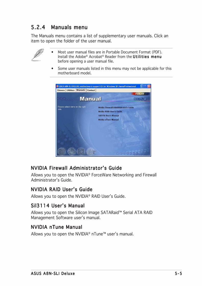
ASUS A8N-SL I De luxeASUS A8N-SL I De luxeASUS A8N-SL I De luxeASUS A8N-SL I De luxeASUS A8N-SL I De luxe 5 - 55 - 55 - 55 - 55 - 5
5.2.45.2.45.2.45.2.45.2.4 Manuals menuManuals menuManuals menuManuals menuManuals menu
The Manuals menu contains a list of supplementary user manuals. Click anitem to open the folder of the user manual.
• Most user manual files are in Portable Document Format (PDF).Install the Adobe® Acrobat® Reader from the Ut i l i t i es menuUt i l i t i es menuUt i l i t i es menuUt i l i t i es menuUt i l i t i es menubefore opening a user manual file.
• Some user manuals listed in this menu may not be applicable for thismotherboard model.
NVIDIA Firewall Administrator’s GuideNVIDIA Firewall Administrator’s GuideNVIDIA Firewall Administrator’s GuideNVIDIA Firewall Administrator’s GuideNVIDIA Firewall Administrator’s Guide
Allows you to open the NVIDIA® ForceWare Networking and FirewallAdministrator’s Guide.
NVIDIA RAID User’s GuideNVIDIA RAID User’s GuideNVIDIA RAID User’s GuideNVIDIA RAID User’s GuideNVIDIA RAID User’s Guide
Allows you to open the NVIDIA® RAID User’s Guide.
Si l3114 User’s ManualSil3114 User’s ManualSil3114 User’s ManualSil3114 User’s ManualSil3114 User’s Manual
Allows you to open the Silicon Image SATARaid™ Serial ATA RAIDManagement Software user’s manual.
NVIDIA nTune ManualNVIDIA nTune ManualNVIDIA nTune ManualNVIDIA nTune ManualNVIDIA nTune Manual
Allows you to open the NVIDIA® nTune™ user’s manual.
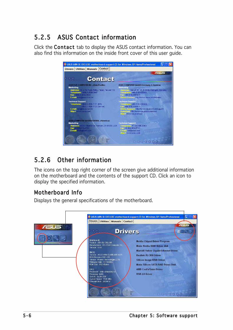
5 - 65 - 65 - 65 - 65 - 6 Chapter 5 : Software supportChapter 5 : Software supportChapter 5 : Software supportChapter 5 : Software supportChapter 5 : Software support
5.2.55.2.55.2.55.2.55.2.5 ASUS Contact informationASUS Contact informationASUS Contact informationASUS Contact informationASUS Contact information
Click the Contact Contact Contact Contact Contact tab to display the ASUS contact information. You canalso find this information on the inside front cover of this user guide.
5.2.65.2.65.2.65.2.65.2.6 Other informationOther informationOther informationOther informationOther information
The icons on the top right corner of the screen give additional informationon the motherboard and the contents of the support CD. Click an icon todisplay the specified information.
Motherboard InfoMotherboard InfoMotherboard InfoMotherboard InfoMotherboard Info
Displays the general specifications of the motherboard.
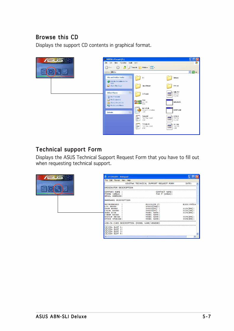
ASUS A8N-SL I De luxeASUS A8N-SL I De luxeASUS A8N-SL I De luxeASUS A8N-SL I De luxeASUS A8N-SL I De luxe 5 - 75 - 75 - 75 - 75 - 7
Browse this CDBrowse this CDBrowse this CDBrowse this CDBrowse this CD
Displays the support CD contents in graphical format.
Technical support FormTechnical support FormTechnical support FormTechnical support FormTechnical support Form
Displays the ASUS Technical Support Request Form that you have to fill outwhen requesting technical support.

5 - 85 - 85 - 85 - 85 - 8 Chapter 5 : Software supportChapter 5 : Software supportChapter 5 : Software supportChapter 5 : Software supportChapter 5 : Software support
Fi le l istFi lel istFi lel istFi lel istFi lel ist
Displays the contents of the support CD and a brief description of each intext format.

ASUS A8N-SL I De luxeASUS A8N-SL I De luxeASUS A8N-SL I De luxeASUS A8N-SL I De luxeASUS A8N-SL I De luxe 5 - 95 - 95 - 95 - 95 - 9
5.4 Software information
Most of the applications in the support CD have wizards that willconveniently guide you through the installation. View the online help orreadme file that came with the software application for more information.
5.4.15.4.15.4.15.4.15.4.1 ASUS MyLogo2™ASUS MyLogo2™ASUS MyLogo2™ASUS MyLogo2™ASUS MyLogo2™
The ASUS MyLogo2™ utility lets you customize the boot logo. The bootlogo is the image that appears on screen during the Power-On Self-Tests(POST). The ASUS MyLogo2™ is automatically installed when you install theASUS Update ASUS Update ASUS Update ASUS Update ASUS Update utility from the support CD. See section “5.2.3 Utilitiesmenu” for details.
To launch the ASUS MyLogo2™:
1. Launch the ASUS Update utility. Refer to section “4.1.5 ASUS Updateutility” for details.
2. Select Opt ions Opt ions Opt ions Opt ions Opt ions from the drop down menu, then click NextNextNextNextNext.
3. Check the option Launch MyLogo to replace system bootLaunch MyLogo to replace system bootLaunch MyLogo to replace system bootLaunch MyLogo to replace system bootLaunch MyLogo to replace system bootlogo before f lash ing BIOSlogo before f lash ing BIOSlogo before f lash ing BIOSlogo before f lash ing BIOSlogo before f lash ing BIOS, then click NextNextNextNextNext.
4. Select Update BIOS from a f i leUpdate BIOS from a f i leUpdate BIOS from a f i leUpdate BIOS from a f i leUpdate BIOS from a f i le from the drop down menu, thenclick NextNextNextNextNext.
5. When prompted, locate the newBIOS file, then click NextNextNextNextNext. TheASUS MyLogo2 window appears.
6. From the left window pane, selectthe folder that contains the imageyou intend to use as your bootlogo.
• Before using the ASUS MyLogo2™, use the Award BIOS Flash utilityto make a copy of your original BIOS file, or obtain the latest BIOSversion from the ASUS website. See section “4.1.2 Updating theBIOS”.
• Make sure that the BIOS item Fu l l Screen Logo Fu l l Screen Logo Fu l l Screen Logo Fu l l Screen Logo Fu l l Screen Logo is set to[Enabled] if you wish to use ASUS MyLogo2. See section “4.6.2Boot Settings Configuration”.
• You can create your own boot logo image in GIF, JPG, or BMP fileformats.

5 -105 -105 -105 -105 -10 Chapter 5 : Software supportChapter 5 : Software supportChapter 5 : Software supportChapter 5 : Software supportChapter 5 : Software support
9. When the screen returns to the ASUS Update utility, flash the originalBIOS to load the new boot logo.
10. After flashing the BIOS, restart the computer to display the new bootlogo during POST.
8. Adjust the boot image to yourdesired size by selecting a valueon the Rat io Rat io Rat io Rat io Rat io box.
7. When the logo images appear onthe right window pane, select animage to enlarge by clicking on it.
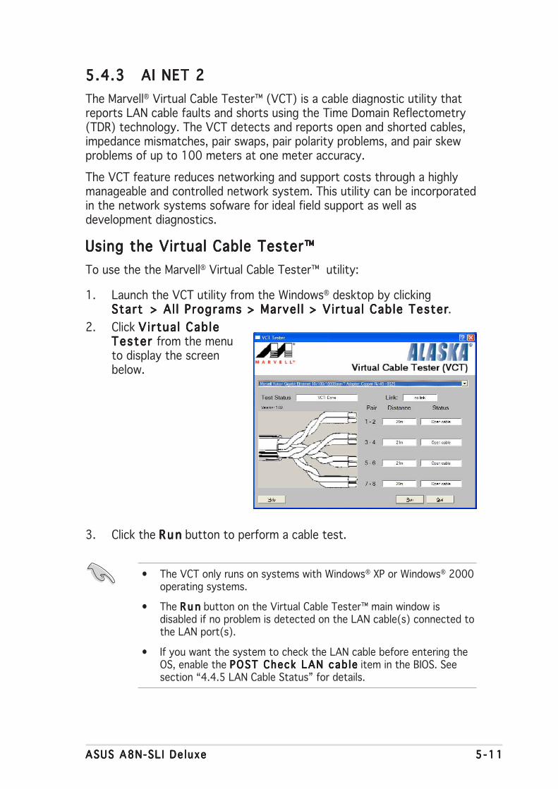
ASUS A8N-SL I De luxeASUS A8N-SL I De luxeASUS A8N-SL I De luxeASUS A8N-SL I De luxeASUS A8N-SL I De luxe 5 -115 -115 -115 -115 -11
3. Click the R unRunRunRunRun button to perform a cable test.
5.4.35.4.35.4.35.4.35.4.3 AI NET 2AI NET 2AI NET 2AI NET 2AI NET 2
The Marvell® Virtual Cable Tester™ (VCT) is a cable diagnostic utility thatreports LAN cable faults and shorts using the Time Domain Reflectometry(TDR) technology. The VCT detects and reports open and shorted cables,impedance mismatches, pair swaps, pair polarity problems, and pair skewproblems of up to 100 meters at one meter accuracy.
The VCT feature reduces networking and support costs through a highlymanageable and controlled network system. This utility can be incorporatedin the network systems sofware for ideal field support as well asdevelopment diagnostics.
Using the Virtual Cable Tester™Using the Virtual Cable Tester™Using the Virtual Cable Tester™Using the Virtual Cable Tester™Using the Virtual Cable Tester™
To use the the Marvell® Virtual Cable Tester™ utility:
1. Launch the VCT utility from the Windows® desktop by clickingStart > Al l Programs > Marvel l > Virtua l Cable TesterStart > Al l Programs > Marvel l > Virtua l Cable TesterStart > Al l Programs > Marvel l > Virtua l Cable TesterStart > Al l Programs > Marvel l > Virtua l Cable TesterStart > Al l Programs > Marvel l > Virtua l Cable Tester.
2. Click Vi rtua l CableVirtua l CableVirtua l CableVirtua l CableVirtua l CableTester Tester Tester Tester Tester from the menuto display the screenbelow.
• The VCT only runs on systems with Windows® XP or Windows® 2000operating systems.
• The R u nR u nR u nR u nR u n button on the Virtual Cable Tester™ main window isdisabled if no problem is detected on the LAN cable(s) connected tothe LAN port(s).
• If you want the system to check the LAN cable before entering theOS, enable the POST Check LAN cab lePOST Check LAN cab lePOST Check LAN cab lePOST Check LAN cab lePOST Check LAN cab le item in the BIOS. Seesection “4.4.5 LAN Cable Status” for details.
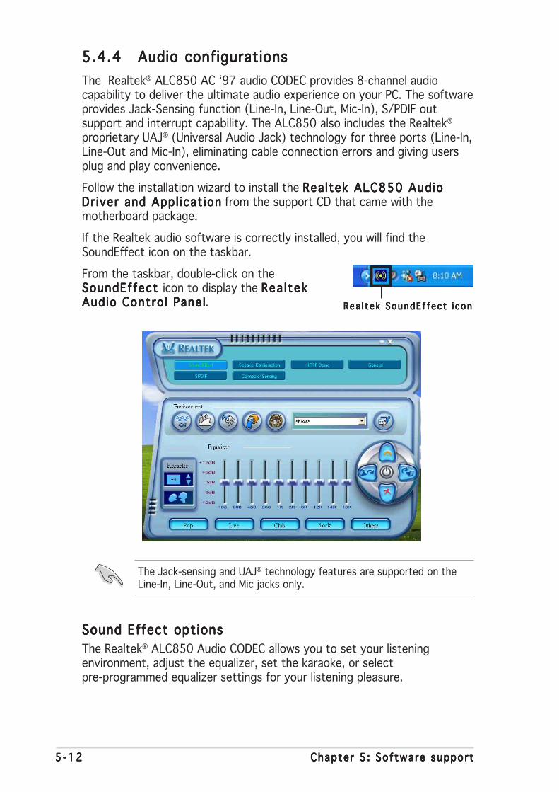
5 -125 -125 -125 -125 -12 Chapter 5 : Software supportChapter 5 : Software supportChapter 5 : Software supportChapter 5 : Software supportChapter 5 : Software support
5.4.45.4.45.4.45.4.45.4.4 Audio configurationsAudio configurationsAudio configurationsAudio configurationsAudio configurations
The Realtek® ALC850 AC ‘97 audio CODEC provides 8-channel audiocapability to deliver the ultimate audio experience on your PC. The softwareprovides Jack-Sensing function (Line-In, Line-Out, Mic-In), S/PDIF outsupport and interrupt capability. The ALC850 also includes the Realtek®
proprietary UAJ® (Universal Audio Jack) technology for three ports (Line-In,Line-Out and Mic-In), eliminating cable connection errors and giving usersplug and play convenience.
Follow the installation wizard to install the Realtek ALC850 AudioRealtek ALC850 AudioRealtek ALC850 AudioRealtek ALC850 AudioRealtek ALC850 AudioDr iver and Appl icat ionDr iver and Appl icat ionDr iver and Appl icat ionDr iver and Appl icat ionDr iver and Appl icat ion from the support CD that came with themotherboard package.
If the Realtek audio software is correctly installed, you will find theSoundEffect icon on the taskbar.
From the taskbar, double-click on theSoundEffect SoundEffect SoundEffect SoundEffect SoundEffect icon to display the Rea l tekRea l tekRea l tekRea l tekRea l tekAudio Contro l PanelAudio Contro l PanelAudio Contro l PanelAudio Contro l PanelAudio Contro l Panel.
Sound Effect optionsSound Effect optionsSound Effect optionsSound Effect optionsSound Effect options
The Realtek® ALC850 Audio CODEC allows you to set your listeningenvironment, adjust the equalizer, set the karaoke, or selectpre-programmed equalizer settings for your listening pleasure.
The Jack-sensing and UAJ® technology features are supported on theLine-In, Line-Out, and Mic jacks only.
Rea l t ek SoundE f fec t i conRea l tek SoundE f fec t i conRea l tek SoundE f fec t i conRea l tek SoundE f fec t i conRea l tek SoundE f fec t i con
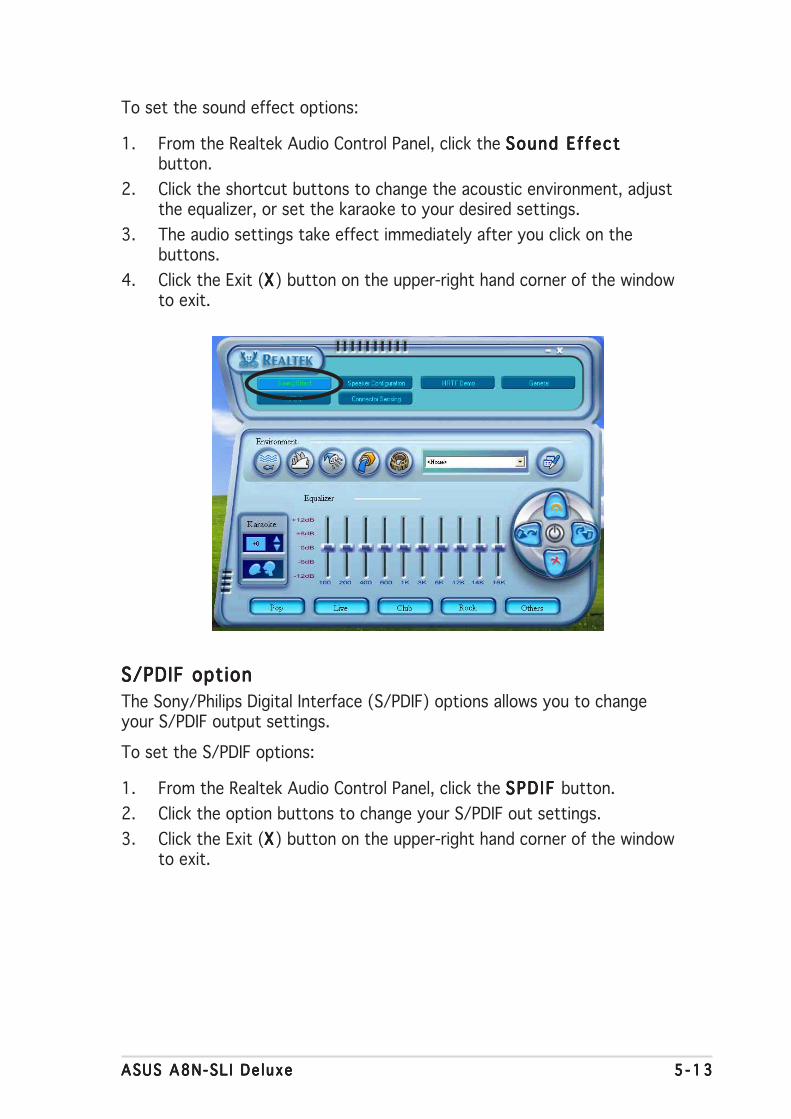
ASUS A8N-SL I De luxeASUS A8N-SL I De luxeASUS A8N-SL I De luxeASUS A8N-SL I De luxeASUS A8N-SL I De luxe 5 -135 -135 -135 -135 -13
S/PDIF optionS/PDIF optionS/PDIF optionS/PDIF optionS/PDIF option
The Sony/Philips Digital Interface (S/PDIF) options allows you to changeyour S/PDIF output settings.
To set the S/PDIF options:
1. From the Realtek Audio Control Panel, click the SPD IF SPD IF SPD IF SPD IF SPD IF button.
2. Click the option buttons to change your S/PDIF out settings.
3. Click the Exit (XXXXX) button on the upper-right hand corner of the windowto exit.
To set the sound effect options:
1. From the Realtek Audio Control Panel, click the Sound EffectSound EffectSound EffectSound EffectSound Effectbutton.
2. Click the shortcut buttons to change the acoustic environment, adjustthe equalizer, or set the karaoke to your desired settings.
3. The audio settings take effect immediately after you click on thebuttons.
4. Click the Exit (XXXXX) button on the upper-right hand corner of the windowto exit.

5 -145 -145 -145 -145 -14 Chapter 5 : Software supportChapter 5 : Software supportChapter 5 : Software supportChapter 5 : Software supportChapter 5 : Software support
Speaker ConfigurationSpeaker ConfigurationSpeaker ConfigurationSpeaker ConfigurationSpeaker Configuration
This option allows you to set your speaker configuration.
To set the speaker configuration:
1. From the Realtek Audio Control Panel, click the SpeakerSpeakerSpeakerSpeakerSpeakerConf igurat ion Conf igurat ion Conf igurat ion Conf igurat ion Conf igurat ion button.
2. Select from the combo list box your current speaker setup, then clickAuto TestAuto TestAuto TestAuto TestAuto Test to test your settings.
3. Click the UAJ Automat icUAJ Automat icUAJ Automat icUAJ Automat icUAJ Automat ic button to enable or disable the UniversalAudio Jack(UAJ®) technology feature.
4. Click the Exit (XXXXX) button on the upper-right hand corner of the windowto exit.
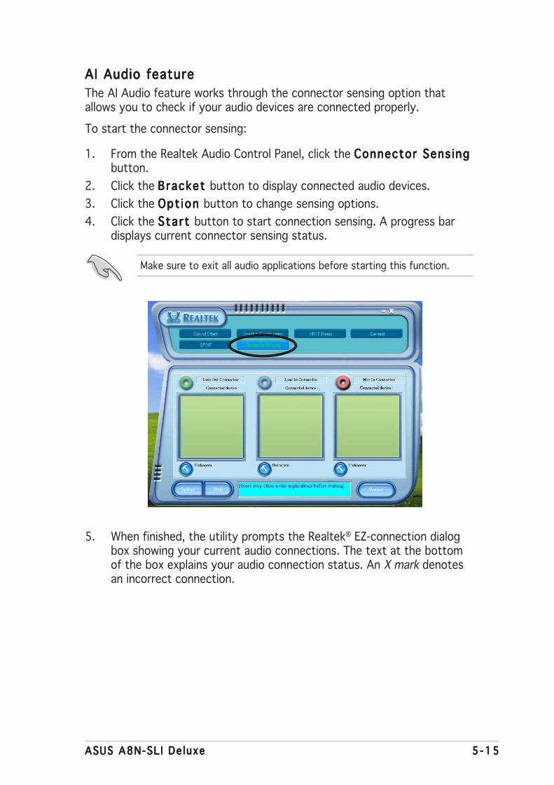
ASUS A8N-SL I De luxeASUS A8N-SL I De luxeASUS A8N-SL I De luxeASUS A8N-SL I De luxeASUS A8N-SL I De luxe 5 -155 -155 -155 -155 -15
5. When finished, the utility prompts the Realtek® EZ-connection dialogbox showing your current audio connections. The text at the bottomof the box explains your audio connection status. An X mark denotesan incorrect connection.
AI Audio featureAI Audio featureAI Audio featureAI Audio featureAI Audio feature
The AI Audio feature works through the connector sensing option thatallows you to check if your audio devices are connected properly.
To start the connector sensing:
1. From the Realtek Audio Control Panel, click the Connector Sens ingConnector Sens ingConnector Sens ingConnector Sens ingConnector Sens ingbutton.
2. Click the Bracket Bracket Bracket Bracket Bracket button to display connected audio devices.
3. Click the Opt ion Opt ion Opt ion Opt ion Opt ion button to change sensing options.
4. Click the Start Start Start Start Start button to start connection sensing. A progress bardisplays current connector sensing status.
Make sure to exit all audio applications before starting this function.
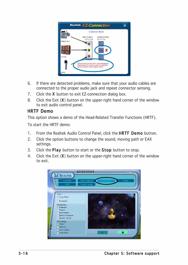
5 -165 -165 -165 -165 -16 Chapter 5 : Software supportChapter 5 : Software supportChapter 5 : Software supportChapter 5 : Software supportChapter 5 : Software support
6. If there are detected problems, make sure that your audio cables areconnected to the proper audio jack and repeat connector sensing.
7. Click the X X X X X button to exit EZ-connection dialog box.
8. Click the Exit (XXXXX) button on the upper-right hand corner of the windowto exit audio control panel.
HRTF DemoHRTF DemoHRTF DemoHRTF DemoHRTF Demo
This option shows a demo of the Head-Related Transfer Functions (HRTF).
To start the HRTF demo:
1. From the Realtek Audio Control Panel, click the HRTF Demo HRTF Demo HRTF Demo HRTF Demo HRTF Demo button.
2. Click the option buttons to change the sound, moving path or EAXsettings.
3. Click the P l ay P l ay P l ay P l ay P l ay button to start or the Stop Stop Stop Stop Stop button to stop.
4. Click the Exit (XXXXX) button on the upper-right hand corner of the windowto exit.
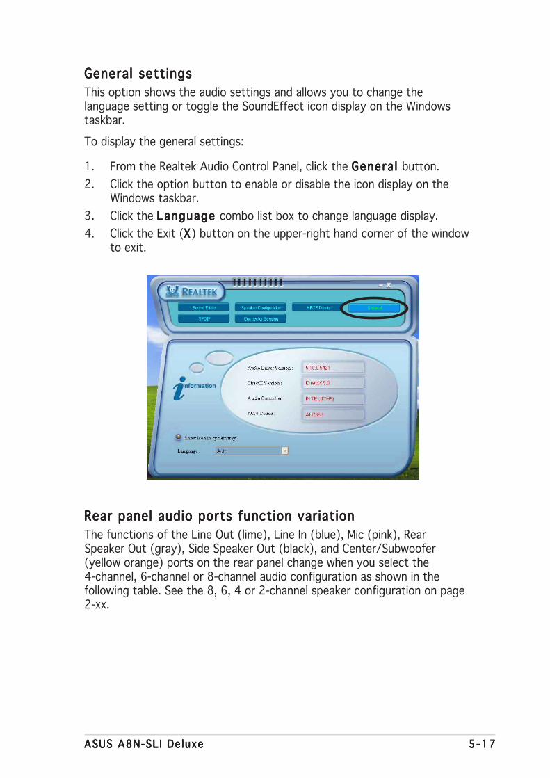
ASUS A8N-SL I De luxeASUS A8N-SL I De luxeASUS A8N-SL I De luxeASUS A8N-SL I De luxeASUS A8N-SL I De luxe 5 -175 -175 -175 -175 -17
Rear panel audio ports function variationRear panel audio ports function variationRear panel audio ports function variationRear panel audio ports function variationRear panel audio ports function variation
The functions of the Line Out (lime), Line In (blue), Mic (pink), RearSpeaker Out (gray), Side Speaker Out (black), and Center/Subwoofer(yellow orange) ports on the rear panel change when you select the4-channel, 6-channel or 8-channel audio configuration as shown in thefollowing table. See the 8, 6, 4 or 2-channel speaker configuration on page2-xx.
General settingsGeneral settingsGeneral settingsGeneral settingsGeneral settings
This option shows the audio settings and allows you to change thelanguage setting or toggle the SoundEffect icon display on the Windowstaskbar.
To display the general settings:
1. From the Realtek Audio Control Panel, click the Genera l Genera l Genera l Genera l Genera l button.
2. Click the option button to enable or disable the icon display on theWindows taskbar.
3. Click the Language Language Language Language Language combo list box to change language display.
4. Click the Exit (XXXXX) button on the upper-right hand corner of the windowto exit.
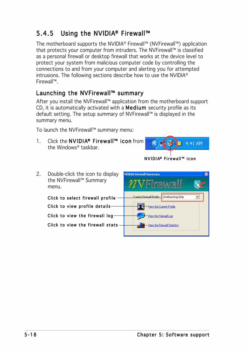
5 -185 -185 -185 -185 -18 Chapter 5 : Software supportChapter 5 : Software supportChapter 5 : Software supportChapter 5 : Software supportChapter 5 : Software support
5.4.55.4.55.4.55.4.55.4.5 Using the NVIDIAUsing the NVIDIAUsing the NVIDIAUsing the NVIDIAUsing the NVIDIA®®®®® Firewall™ Firewall™ Firewall™ Firewall™ Firewall™
The motherboard supports the NVIDIA® Firewall™ (NVFirewall™) applicationthat protects your computer from intruders. The NVFirewall™ is classifiedas a personal firewall or desktop firewall that works at the device level toprotect your system from malicious computer code by controlling theconnections to and from your computer and alerting you for attemptedintrusions. The following sections describe how to use the NVIDIA®
Firewall™.
Launching the NVFirewall™ summaryLaunching the NVFirewall™ summaryLaunching the NVFirewall™ summaryLaunching the NVFirewall™ summaryLaunching the NVFirewall™ summary
After you install the NVFirewall™ application from the motherboard supportCD, it is automatically activated with a Med ium Med ium Med ium Med ium Med ium security profile as itsdefault setting. The setup summary of NVFirewall™ is displayed in thesummary menu.
To launch the NVFirewall™ summary menu:
1. Click the NVID IANVID IANVID IANVID IANVID IA®®®®® F i rewal l™ icon F i rewal l™ icon F i rewal l™ icon F i rewal l™ icon F i rewal l™ icon fromthe Windows® taskbar.
N V I D I AN V I D I AN V I D I AN V I D I AN V I D I A®®®®® F i r ewa l l™ i con F i r ewa l l™ i con F i r ewa l l™ i con F i r ewa l l™ i con F i r ewa l l™ i con
2. Double-click the icon to displaythe NVFirewall™ Summarymenu.
C l i c k to se l ec t f i r ewa l l p ro f i l eC l i c k to se l ec t f i r ewa l l p ro f i l eC l i c k to se l ec t f i r ewa l l p ro f i l eC l i c k to se l ec t f i r ewa l l p ro f i l eC l i c k to se l ec t f i r ewa l l p ro f i l e
C l i c k to v i ew p ro f i l e de ta i l sC l i c k to v i ew p ro f i l e de ta i l sC l i c k to v i ew p ro f i l e de ta i l sC l i c k to v i ew p ro f i l e de ta i l sC l i c k to v i ew p ro f i l e de ta i l s
C l i c k to v i ew the f i r ewa l l l ogC l i c k to v i ew the f i r ewa l l l ogC l i c k to v i ew the f i r ewa l l l ogC l i c k to v i ew the f i r ewa l l l ogC l i c k to v i ew the f i r ewa l l l og
C l i c k to v i ew the f i r ewa l l s ta t sC l i c k to v i ew the f i r ewa l l s ta t sC l i c k to v i ew the f i r ewa l l s ta t sC l i c k to v i ew the f i r ewa l l s ta t sC l i c k to v i ew the f i r ewa l l s ta t s
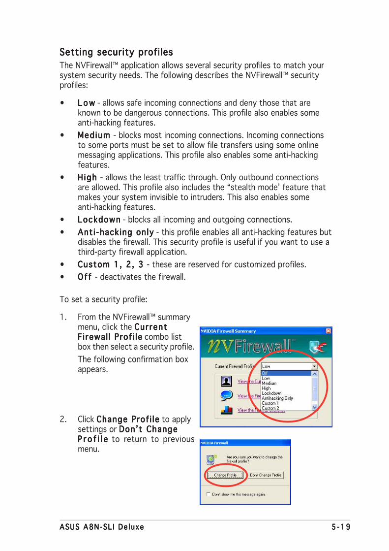
ASUS A8N-SL I De luxeASUS A8N-SL I De luxeASUS A8N-SL I De luxeASUS A8N-SL I De luxeASUS A8N-SL I De luxe 5 -195 -195 -195 -195 -19
Setting security profi lesSetting security profi lesSetting security profi lesSetting security profi lesSetting security profi les
The NVFirewall™ application allows several security profiles to match yoursystem security needs. The following describes the NVFirewall™ securityprofiles:
• L o wL o wL o wL o wL o w - allows safe incoming connections and deny those that areknown to be dangerous connections. This profile also enables someanti-hacking features.
• Med ium Med ium Med ium Med ium Med ium - blocks most incoming connections. Incoming connectionsto some ports must be set to allow file transfers using some onlinemessaging applications. This profile also enables some anti-hackingfeatures.
• H igh H igh H igh H igh H igh - allows the least traffic through. Only outbound connectionsare allowed. This profile also includes the “stealth mode’ feature thatmakes your system invisible to intruders. This also enables someanti-hacking features.
• LockdownLockdownLockdownLockdownLockdown - blocks all incoming and outgoing connections.
• Ant i -hack ing onlyAnt i -hack ing onlyAnt i -hack ing onlyAnt i -hack ing onlyAnt i -hack ing only - this profile enables all anti-hacking features butdisables the firewall. This security profile is useful if you want to use athird-party firewall application.
• Custom 1, 2, 3 Custom 1, 2, 3 Custom 1, 2, 3 Custom 1, 2, 3 Custom 1, 2, 3 - these are reserved for customized profiles.
• Of f O f f O f f O f f O f f - deactivates the firewall.
To set a security profile:
1. From the NVFirewall™ summarymenu, click the Cur rentCur rentCur rentCur rentCur rentF i rewal l Prof i leF i rewal l Prof i leF i rewal l Prof i leF i rewal l Prof i leF i rewal l Prof i le combo listbox then select a security profile.
The following confirmation boxappears.
2. Click Change Prof i leChange Prof i leChange Prof i leChange Prof i leChange Prof i le to applysettings or Don’t ChangeDon’t ChangeDon’t ChangeDon’t ChangeDon’t ChangeP r o f i l eP r o f i l eP r o f i l eP r o f i l eP r o f i l e to return to previousmenu.
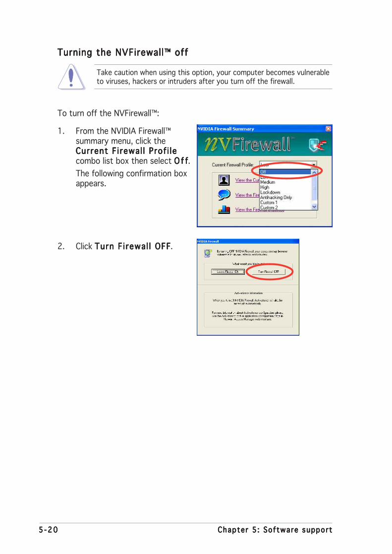
5 -205 -205 -205 -205 -20 Chapter 5 : Software supportChapter 5 : Software supportChapter 5 : Software supportChapter 5 : Software supportChapter 5 : Software support
Turning the NVFirewall™ offTurning the NVFirewall™ offTurning the NVFirewall™ offTurning the NVFirewall™ offTurning the NVFirewall™ off
Take caution when using this option, your computer becomes vulnerableto viruses, hackers or intruders after you turn off the firewall.
To turn off the NVFirewall™:
1. From the NVIDIA Firewall™summary menu, click theCurrent F i rewal l Prof i leCurrent F i rewal l Prof i leCurrent F i rewal l Prof i leCurrent F i rewal l Prof i leCurrent F i rewal l Prof i lecombo list box then select O f fO f fO f fO f fO f f.
The following confirmation boxappears.
2. Click Turn F i rewal l OFFTurn F i rewal l OFFTurn F i rewal l OFFTurn F i rewal l OFFTurn F i rewal l OFF.
ASUS A8N-SL I De luxeASUS A8N-SL I De luxeASUS A8N-SL I De luxeASUS A8N-SL I De luxeASUS A8N-SL I De luxe 5 -215 -215 -215 -215 -21
5.5 RAID configurations
The motherboard comes with the Silicon Image Sil3114 and the NVIDIA®
SLI Southbridge RAID controllers that allow you to configure IDE and SerialATA hard disk drives as RAID sets. The motherboard supports thefollowing RAID configurations.
RA ID 0RAID 0RAID 0RAID 0RAID 0 (Data striping) optimizes two identical hard disk drives to read andwrite data in parallel, interleaved stacks. Two hard disks perform the samework as a single drive but at a sustained data transfer rate, double that ofa single disk alone, thus improving data access and storage. Use of twonew identical hard disk drives is required for this setup.
RA ID 1RAID 1RAID 1RAID 1RAID 1 (Data mirroring) copies and maintains an identical image of datafrom one drive to a second drive. If one drive fails, the disk arraymanagement software directs all applications to the surviving drive as itcontains a complete copy of the data in the other drive. This RAIDconfiguration provides data protection and increases fault tolerance to theentire system. Use two new drives or use an existing drive and a new drivefor this setup. The new drive must be of the same size or larger than theexisting drive.
RAID 0+1RAID 0+1RAID 0+1RAID 0+1RAID 0+1 is data striping and data mirroring combined without parity(redundancy data) having to be calculated and written. With the RAID 0+1configuration you get all the benefits of both RAID 0 and RAID 1configurations. Use four new hard disk drives or use an existing drive andthree new drives for this setup.
RA ID 5RAID 5RAID 5RAID 5RAID 5 stripes both data and parity information across three or more harddisk drives. Among the advantages of RAID 5 configuration include betterHDD performance, fault tolerance, and higher storage capacity. The RAID 5configuration is best suited for transaction processing, relational databaseapplications, enterprise resource planning, and other business systems.Use a minimum of three identical hard disk drives for this setup.
RAID 10RAID 10RAID 10RAID 10RAID 10 is a striped configuration with RAID 1 segments whose segmentsare RAID 1 arrays. This configuration has the same fault tolerance asRAID 1, and has the same overhead for fault-tolerance as mirroring alone.RAID 10 achieves high input/output rates by striping RAID 1 segments. Insome instances, a RAID 10 configuration can sustain multiple simultaneousdrive failure. A minimum of four hard disk drives is required for this setup.
JBODJBODJBODJBODJBOD (Spanning) stands for Just a Bunch of DisksJust a Bunch of DisksJust a Bunch of DisksJust a Bunch of DisksJust a Bunch of Disks and refers to harddisk drives that are not yet configured as a RAID set. This configurationstores the same data redundantly on multiple disks that appear as a singledisk on the operating system. Spanning does not deliver any advantageover using separate disks independently and does not provide faulttolerance or other RAID performance benefits.

5 -225 -225 -225 -225 -22 Chapter 5 : Software supportChapter 5 : Software supportChapter 5 : Software supportChapter 5 : Software supportChapter 5 : Software support
5.5.15.5.15.5.15.5.15.5.1 Installing hard disksInstalling hard disksInstalling hard disksInstalling hard disksInstalling hard disks
The motherboard supports Ultra DMA /133/100/66 and Serial ATA harddisk drives. For optimal performance, install identical drives of the samemodel and capacity when creating a disk array.
Install ing Parallel ATA hard disksInstall ing Parallel ATA hard disksInstall ing Parallel ATA hard disksInstall ing Parallel ATA hard disksInstall ing Parallel ATA hard disks
To install IDE hard disks for a RAID configuration:
1. Set the jumpers of each hard disk as Master/Master or Slave/Slave.
2. Install the hard disks into the drive bays.
3. Connect the HDD signal cables.
4. Connect a 4-pin power cable to the power connector on each drive.
Install ing Serial ATA (SATA) hard disksInstall ing Serial ATA (SATA) hard disksInstall ing Serial ATA (SATA) hard disksInstall ing Serial ATA (SATA) hard disksInstall ing Serial ATA (SATA) hard disks
To install the SATA hard disks for a RAID configuration:
1. Install the SATA hard disks into the drive bays.
2. Connect the SATA signal cables.
3. Connect a SATA power cable to the power connector on each drive.
If you want to boot the system from a hard disk drive included in a RAIDset, copy first the RAID driver from the support CD to a floppy diskbefore you install an operating system to a selected hard disk drive.Refer to section “5.6 Creating a RAID driver disk” for details.
Refer to the RAID controllers user manual in the motherboard supportCD for detailed information on RAID configurations. See section “5.2.4Manuals menu”.
ASUS A8N-SL I De luxeASUS A8N-SL I De luxeASUS A8N-SL I De luxeASUS A8N-SL I De luxeASUS A8N-SL I De luxe 5 -235 -235 -235 -235 -23
5.5.25.5.25.5.25.5.25.5.2 NVIDIANVIDIANVIDIANVIDIANVIDIA®®®®® RAID configurations RAID configurations RAID configurations RAID configurations RAID configurations
The motherboard includes a high performance IDE RAID controllerintegrated in the NVIDIA® SLI southbridge chipset. It supports RAID 0, RAID1, RAID 1+0, and JBOD with four independent Serial ATA channels.
Setting the BIOS RAID itemsSetting the BIOS RAID itemsSetting the BIOS RAID itemsSetting the BIOS RAID itemsSetting the BIOS RAID items
After installing the hard disk drives, make sure to set the necessary RAIDitems in the BIOS before setting your RAID configuration.
To set the BIOS RAID items:
1. Boot the system and press <Del> during the Power-On Self-Test(POST) to enter the BIOS Setup Utility.
2. From the Advanced > Onboard Devices Conf igurat ion >Advanced > Onboard Devices Conf igurat ion >Advanced > Onboard Devices Conf igurat ion >Advanced > Onboard Devices Conf igurat ion >Advanced > Onboard Devices Conf igurat ion >NVRAID Conf igurat ion NVRAID Conf igurat ion NVRAID Conf igurat ion NVRAID Conf igurat ion NVRAID Conf igurat ion menu item in the BIOS set the RA IDRA IDRA IDRA IDRA IDEnab led Enab led Enab led Enab led Enab led item to Enabled. The succeeding items becomeuser-configurable.
3. Select and enable the IDE or SATA drive(s) that you want to configureas RAID. See section “4.4.3 Onboard Devices Configuration” fordetails.
4. Save your changes and Exit Setup.
For detailed descriptions on the NVIDIA® RAID configuration, refer tothe “NVIDIA® RAID User’s Manual” found in your motherboard supportCD.
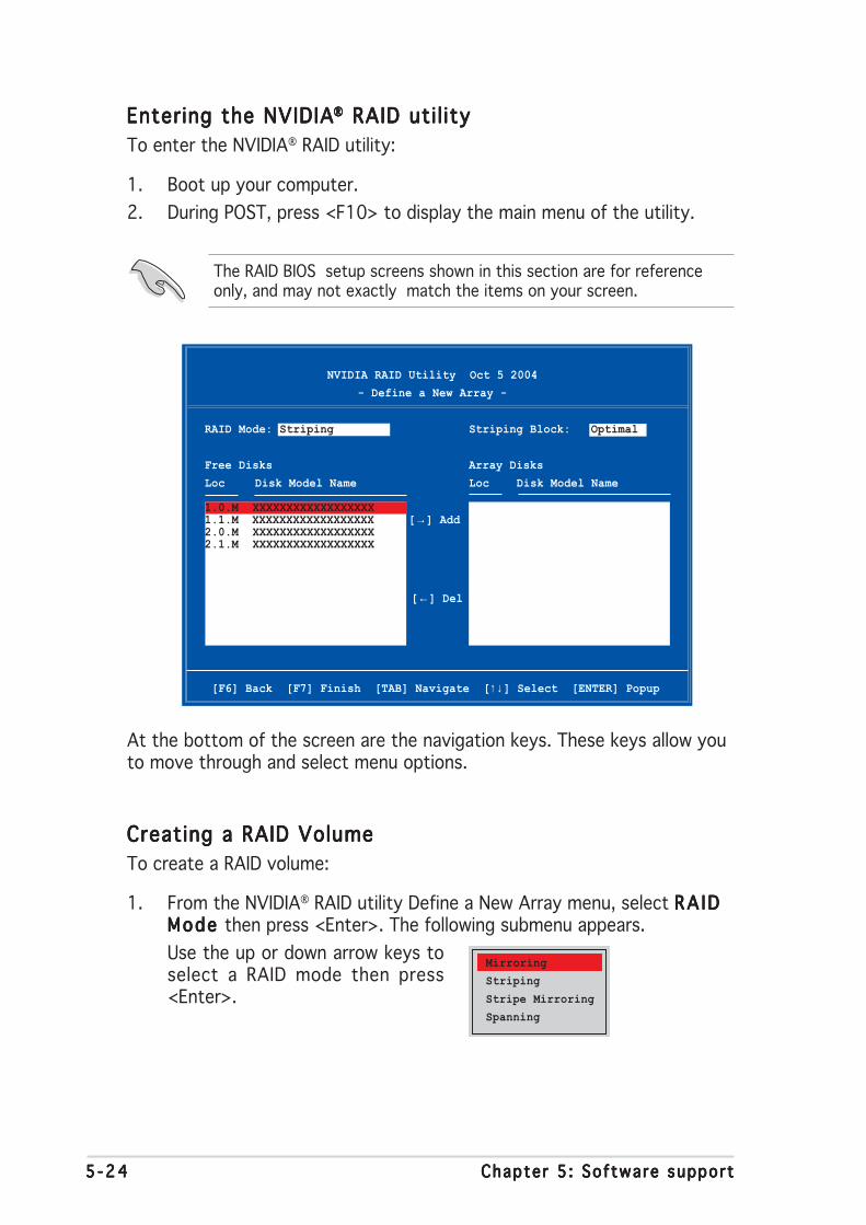
5 -245 -245 -245 -245 -24 Chapter 5 : Software supportChapter 5 : Software supportChapter 5 : Software supportChapter 5 : Software supportChapter 5 : Software support
Entering the NVIDIAEntering the NVIDIAEntering the NVIDIAEntering the NVIDIAEntering the NVIDIA®®®®® RAID uti l ity RAID uti l ity RAID uti l ity RAID uti l ity RAID uti l ity
To enter the NVIDIA® RAID utility:
1. Boot up your computer.
2. During POST, press <F10> to display the main menu of the utility.
The RAID BIOS setup screens shown in this section are for referenceonly, and may not exactly match the items on your screen.
[F6] Back [F7] Finish [TAB] Navigate [↑↓ ] Select [ENTER] Popup
At the bottom of the screen are the navigation keys. These keys allow youto move through and select menu options.
NVIDIA RAID Utility Oct 5 2004
- Define a New Array -
RAID Mode: Striping Striping Block: Optimal
Free Disks Array Disks
Loc Disk Model Name Loc Disk Model Name
1.0.M XXXXXXXXXXXXXXXXXX1.1.M XXXXXXXXXXXXXXXXXX [→] Add2.0.M XXXXXXXXXXXXXXXXXX2.1.M XXXXXXXXXXXXXXXXXX
[←] Del
Creating a RAID VolumeCreating a RAID VolumeCreating a RAID VolumeCreating a RAID VolumeCreating a RAID Volume
To create a RAID volume:
1. From the NVIDIA® RAID utility Define a New Array menu, select RA IDRA IDRA IDRA IDRA IDMode Mode Mode Mode Mode then press <Enter>. The following submenu appears.
Use the up or down arrow keys toselect a RAID mode then press<Enter>.
Mirroring
Striping
Stripe Mirroring
Spanning
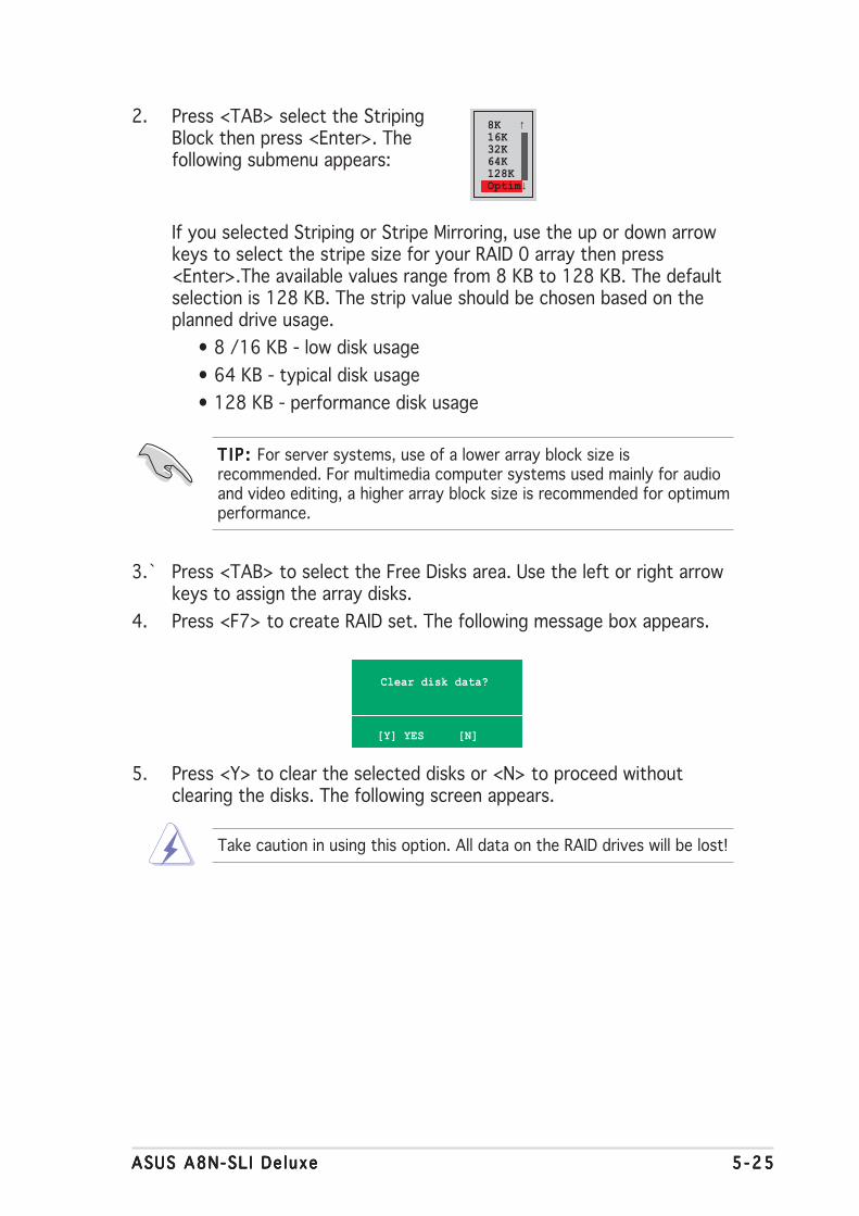
ASUS A8N-SL I De luxeASUS A8N-SL I De luxeASUS A8N-SL I De luxeASUS A8N-SL I De luxeASUS A8N-SL I De luxe 5 -255 -255 -255 -255 -25
T I P : T I P : T I P : T I P : T I P : For server systems, use of a lower array block size isrecommended. For multimedia computer systems used mainly for audioand video editing, a higher array block size is recommended for optimumperformance.
Take caution in using this option. All data on the RAID drives will be lost!
2. Press <TAB> select the StripingBlock then press <Enter>. Thefollowing submenu appears:
If you selected Striping or Stripe Mirroring, use the up or down arrowkeys to select the stripe size for your RAID 0 array then press<Enter>.The available values range from 8 KB to 128 KB. The defaultselection is 128 KB. The strip value should be chosen based on theplanned drive usage.
• 8 /16 KB - low disk usage
• 64 KB - typical disk usage
• 128 KB - performance disk usage
3.` Press <TAB> to select the Free Disks area. Use the left or right arrowkeys to assign the array disks.
4. Press <F7> to create RAID set. The following message box appears.
Clear disk data?
[Y] YES [N]
5. Press <Y> to clear the selected disks or <N> to proceed withoutclearing the disks. The following screen appears.
8K ↑16K32K64K128KOptim↓

5 -265 -265 -265 -265 -26 Chapter 5 : Software supportChapter 5 : Software supportChapter 5 : Software supportChapter 5 : Software supportChapter 5 : Software support
Rebuilding a RAID arrayRebuilding a RAID arrayRebuilding a RAID arrayRebuilding a RAID arrayRebuilding a RAID array
To rebuild a RAID array:
1. From the Array List menu, use the up or down arrow keys to select aRAID array then press <Enter>. The RAID Array details appear.
[Ctrl-X]Exit [↑↓ ]Select [B]Set Boot [N]New Array [ENTER]Detail
NVIDIA RAID Utility Oct 5 2004
- Array List -
Boot Id Status Vendor Array Model Name
No 4 Healthy NVIDIA MIRROR XXX.XXG
A new set of navigation keys is displayed on the bottom of thescreen.
6. Press <Ctrl+X> to save settings and exit.
[R] Rebuild [D] Delete [C] Clear Disk [ENTER] Return
Array 1 : NVIDIA MIRROR XXX.XXG
- Array Detail -
RAID Mode: Mirroring
Striping Width: 1 Striping Block: 64K
Adapt Channel M/S Index Disk Model Name Capacity
2 1 Master 0 XXXXXXXXXXXXXXXXX XXX.XXGB 1 0 Master 1 XXXXXXXXXXXXXXXXX XXX.XXGB

ASUS A8N-SL I De luxeASUS A8N-SL I De luxeASUS A8N-SL I De luxeASUS A8N-SL I De luxeASUS A8N-SL I De luxe 5 -275 -275 -275 -275 -27
A new set of navigation keys is displayed on the bottom of thescreen.
2. Press <R> to rebuild a RAID array. The following screen appears.
3. Use the up or down arrow keys to select a RAID array to rebuild, thenpress <F7>. The following confirmation message appears.
[↑↓ ] Select [F6] Back [F7] Finish
Array 1 : NVIDIA MIRROR XXX.XXG
- Select Disk Inside Array -
RAID Mode: Mirroring
Striping Width: 1 Striping Block: 64K
Adapt Channel M/S Index Disk Model Name Capacity
2 1 Master 0 XXXXXXXXXXXXXXXXX XXX.XXGB 1 0 Master 1 XXXXXXXXXXXXXXXXX XXX.XXGB
Rebuild array?
[ENTER] OK [ESC] Cancel
4. Press <Enter> to start rebuilding array or press <Esc> to cancel.
5. After the rebuild process, the Array list menu appears.

5 -285 -285 -285 -285 -28 Chapter 5 : Software supportChapter 5 : Software supportChapter 5 : Software supportChapter 5 : Software supportChapter 5 : Software support
Deleting a RAID arrayDeleting a RAID arrayDeleting a RAID arrayDeleting a RAID arrayDeleting a RAID array
To delete a RAID array:
1. From the Array List menu, use the up or down arrow keys to select aRAID array then press <Enter>. The RAID Array details appear.
[R] Rebuild [D] Delete [C] Clear Disk [ENTER] Return
Array 1 : NVIDIA MIRROR XXX.XXG
- Array Detail -
RAID Mode: Mirroring
Striping Width: 1 Striping Block: 64K
Adapt Channel M/S Index Disk Model Name Capacity
2 1 Master 0 XXXXXXXXXXXXXXXXX XXX.XXGB 1 0 Master 1 XXXXXXXXXXXXXXXXX XXX.XXGB
A new set of navigation keys is displayed on the bottom of thescreen.
2. Press <D> to delete a RAID array. The following confirmation messageappears.
Delete this array?
[Y] YES [N] No
4. If you selected Yes, the Define a New Array menu appears.
Take caution in using this option. All data on the RAID drives will be lost!
3. Press <Y> to delete array or press <N> to cancel.

ASUS A8N-SL I De luxeASUS A8N-SL I De luxeASUS A8N-SL I De luxeASUS A8N-SL I De luxeASUS A8N-SL I De luxe 5 -295 -295 -295 -295 -29
Clearing a disk dataClearing a disk dataClearing a disk dataClearing a disk dataClearing a disk data
To clear disk data:
1. From the Array List menu, use the up or down arrow keys to select aRAID array then press <Enter>. The RAID Array details appear.
[R] Rebuild [D] Delete [C] Clear Disk [ENTER] Return
Array 1 : NVIDIA MIRROR XXX.XXG
- Array Detail -
RAID Mode: Mirroring
Striping Width: 1 Striping Block: 64K
Adapt Channel M/S Index Disk Model Name Capacity
2 1 Master 0 XXXXXXXXXXXXXXXXX XXX.XXGB 1 0 Master 1 XXXXXXXXXXXXXXXXX XXX.XXGB
A new set of navigation keys is displayed on the bottom of thescreen.
2. Press <C> to clear disk. The following confirmation message appears.
Take caution in using this option. All data on the RAID drives will be lost!
Clear disk data?
[Y] YES [N]
5. Press <Y> to clear the disk data or press <N> to cancel.

5 -305 -305 -305 -305 -30 Chapter 5 : Software supportChapter 5 : Software supportChapter 5 : Software supportChapter 5 : Software supportChapter 5 : Software support
5.5.35.5.35.5.35.5.35.5.3 Silicon Image RAID configurationsSilicon Image RAID configurationsSilicon Image RAID configurationsSilicon Image RAID configurationsSilicon Image RAID configurations
The Silicon Image RAID controller supports RAID 0, RAID 1, RAID 10, JBOD,and RAID 5 configurations. Use the Silicon Image RAID utility to configure adisk array.
Setting the BIOS RAID itemsSetting the BIOS RAID itemsSetting the BIOS RAID itemsSetting the BIOS RAID itemsSetting the BIOS RAID items
After installing the hard disk drives, make sure to set the necessary RAIDitems in the BIOS before setting your RAID configuration.
To set the BIOS RAID items:
1. Boot the system and press <Del> during the Power-On Self-Test(POST) to enter the BIOS Setup Utility.
2. From the Advanced > Onboard Devices Conf igurat ion Advanced > Onboard Devices Conf igurat ion Advanced > Onboard Devices Conf igurat ion Advanced > Onboard Devices Conf igurat ion Advanced > Onboard Devices Conf igurat ion menuitem in the BIOS set the S i l icon Image Contro l ler S i l icon Image Contro l ler S i l icon Image Contro l ler S i l icon Image Contro l ler S i l icon Image Contro l ler item to RAIDMode. See section “4.4.6 Onboard Devices Configuration” for details.
3. Save your changes and Exit Setup.
Launching the Sil icon Image Array Management SoftwareLaunching the Sil icon Image Array Management SoftwareLaunching the Sil icon Image Array Management SoftwareLaunching the Sil icon Image Array Management SoftwareLaunching the Sil icon Image Array Management Software
Launch the Silicon Image Array Management software from Windows® XP byclicking the Sta r tSta r tSta r tSta r tSta r t button and selecting Al l Programs > S i l icon ImageAl l Programs > S i l icon ImageAl l Programs > S i l icon ImageAl l Programs > S i l icon ImageAl l Programs > S i l icon Image> Sam> Sam> Sam> Sam> Sam
• For details on the Silicon Image SATARaid™ RAID configuration, referto the “Sil3114 User’s Manual” in your motherboard support CD.
• You can only set the SATALink™ RAID 5 and JBOD configurationusing the SATALink™ SATA RAID Management Software.
• Make sure to install the Silicon Image SATA Link Sil 3114 driver andthe Silicon Image RAID 5 Array Management Utility from the supportCD before using RAID 5 configuration.
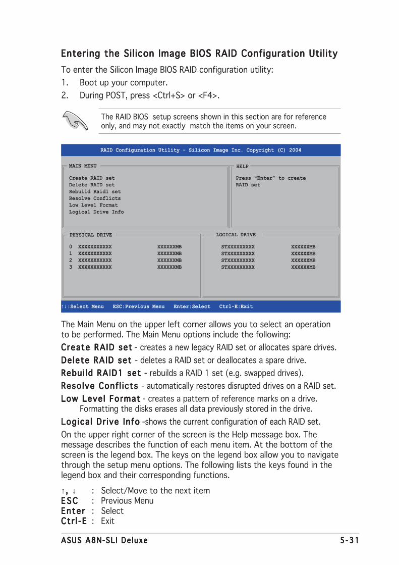
ASUS A8N-SL I De luxeASUS A8N-SL I De luxeASUS A8N-SL I De luxeASUS A8N-SL I De luxeASUS A8N-SL I De luxe 5 -315 -315 -315 -315 -31
Entering the Sil icon Image BIOS RAID Configuration Util ityEntering the Sil icon Image BIOS RAID Configuration Util ityEntering the Sil icon Image BIOS RAID Configuration Util ityEntering the Sil icon Image BIOS RAID Configuration Util ityEntering the Sil icon Image BIOS RAID Configuration Util ity
To enter the Silicon Image BIOS RAID configuration utility:
1. Boot up your computer.
2. During POST, press <Ctrl+S> or <F4>.
The RAID BIOS setup screens shown in this section are for referenceonly, and may not exactly match the items on your screen.
The Main Menu on the upper left corner allows you to select an operationto be performed. The Main Menu options include the following:
Create RAID setCreate RAID setCreate RAID setCreate RAID setCreate RAID set - creates a new legacy RAID set or allocates spare drives.
Delete RAID set Delete RAID set Delete RAID set Delete RAID set Delete RAID set - deletes a RAID set or deallocates a spare drive.
Rebui ld RAID1 set Rebui ld RAID1 set Rebui ld RAID1 set Rebui ld RAID1 set Rebui ld RAID1 set - rebuilds a RAID 1 set (e.g. swapped drives).
Resolve Conf l icts Resolve Conf l icts Resolve Conf l icts Resolve Conf l icts Resolve Conf l icts - automatically restores disrupted drives on a RAID set.
Low Level FormatLow Level FormatLow Level FormatLow Level FormatLow Level Format - creates a pattern of reference marks on a drive.Formatting the disks erases all data previously stored in the drive.
Logica l Dr ive InfoLogica l Dr ive InfoLogica l Dr ive InfoLogica l Dr ive InfoLogica l Dr ive Info -shows the current configuration of each RAID set.
On the upper right corner of the screen is the Help message box. Themessage describes the function of each menu item. At the bottom of thescreen is the legend box. The keys on the legend box allow you to navigatethrough the setup menu options. The following lists the keys found in thelegend box and their corresponding functions.
↑ , , , , , ↓ : Select/Move to the next itemE S CE S CE S CE S CE S C : Previous MenuEnterEnte rEnte rEnte rEnte r : SelectCt r l -ECt r l -ECt r l -ECt r l -ECt r l -E : Exit
Create RAID setDelete RAID setRebuild Raid1 setResolve ConflictsLow Level FormatLogical Drive Info
RAID Configuration Utility - Silicon Image Inc. Copyright (C) 2004
↑↓ :Select Menu ESC:Previous Menu Enter:Select Ctrl-E:Exit
MAIN MENU
PHYSICAL DRIVE
0 XXXXXXXXXXX XXXXXXMB1 XXXXXXXXXXX XXXXXXMB2 XXXXXXXXXXX XXXXXXMB3 XXXXXXXXXXX XXXXXXMB
STXXXXXXXXX XXXXXXMBSTXXXXXXXXX XXXXXXMBSTXXXXXXXXX XXXXXXMBSTXXXXXXXXX XXXXXXMB
LOGICAL DRIVE
HELP
Press “Enter” to createRAID set

5 -325 -325 -325 -325 -32 Chapter 5 : Software supportChapter 5 : Software supportChapter 5 : Software supportChapter 5 : Software supportChapter 5 : Software support
Manual conf igurat ionManual conf igurat ionManual conf igurat ionManual conf igurat ionManual conf igurat ion
a. Select Manua lManua lManua lManua lManua lconf igurat ionconf igurat ionconf igurat ionconf igurat ionconf igurat ion andpress <Enter>. Thefollowing pop-upmenu appears.
b. Use the up or downarrow keys to selecta chunk sizeappropriate to yourdrive usage thenpress <Enter>.
MAIN MENU
Auto configurationManual configuration
chunk size4K8K16K32K64K128K
Creating a RAID 0 set (Striped)Creating a RAID 0 set (Striped)Creating a RAID 0 set (Striped)Creating a RAID 0 set (Striped)Creating a RAID 0 set (Striped)
To create a RAID set:
1. From the Silicon Imageconfiguration utilitymain menu, selectCreate RAID setCreate RAID setCreate RAID setCreate RAID setCreate RAID setthen press <Enter> todisplay an option menu.
2. Select RA ID 0RAID 0RAID 0RAID 0RAID 0 thenpress <Enter> todisplay the following.
3. Select your desired method of configuration.
Auto conf igurat ionAuto conf igurat ionAuto conf igurat ionAuto conf igurat ionAuto conf igurat ion
a. Select Auto Configuration the press <Enter>.
b. The utility prompts a message to input the RAID size, use the upor down arrow keys to set the RAID size then press <Enter>.
c. Press <Y> to confirm or <N> to return to the Main Menu.
MAIN MENU
Auto configurationManual configuration
By default, Auto configuration sets the stripe size to 64K and sets thelogical drives based on the physical drives installed.
MAIN MENU
Create RAID setDelete RAID setRebuild Raid1 setResolve ConflictsLow Level FormatLogical Drive Info
RAID0RAID1RAID5RAID10
SPARE DRIVEJBOD

ASUS A8N-SL I De luxeASUS A8N-SL I De luxeASUS A8N-SL I De luxeASUS A8N-SL I De luxeASUS A8N-SL I De luxe 5 -335 -335 -335 -335 -33
2. Select RA ID 1RAID 1RAID 1RAID 1RAID 1 thenpress <Enter> todisplay the following.
MAIN MENU
Auto configurationManual configuration
c. The selection bar moves tothe Physical Drive menu.Using the up or down arrowkeys, select a drive thenpress <Enter> to set thefirst drive of the RAID set.
d. Repeat step c to set the second, third, and fourth drive. Thenumber of available drives depend on the installed and enabledphysical drives in the system.
e. The utility prompts a message to input the RAID size, use the upor down arrow keys to set the RAID size then press <Enter>.
f. Press <Y> to confirm or <N> to return to the Main Menu.
T I P : T I P : T I P : T I P : T I P : For server systems, use of a lower array block size isrecommended. For multimedia computer systems used mainly for audioand video editing, a higher array block size is recommended for optimumperformance.
PHYSICAL DRIVE
0 XXXXXXXXXXX XXXXXXMB1 XXXXXXXXXXX XXXXXXMB2 XXXXXXXXXXX XXXXXXMB3 XXXXXXXXXXX XXXXXXMB
Creating a RAID 1 set (Mirrored)Creating a RAID 1 set (Mirrored)Creating a RAID 1 set (Mirrored)Creating a RAID 1 set (Mirrored)Creating a RAID 1 set (Mirrored)
To create a RAID 1 set:
1. From the Silicon Imageconfiguration utilitymain menu, selectCreate RAID setCreate RAID setCreate RAID setCreate RAID setCreate RAID setthen press <Enter>. Thefollowing sub-menuappears.
MAIN MENU
Create RAID setDelete RAID setRebuild Raid1 setResolve ConflictsLow Level FormatLogical Drive Info
RAID0RAID1RAID10
SPARE DRIVE
RAID0RAID1RAID5RAID10
SPARE DRIVEJBOD

5 -345 -345 -345 -345 -34 Chapter 5 : Software supportChapter 5 : Software supportChapter 5 : Software supportChapter 5 : Software supportChapter 5 : Software support
PHYSICAL DRIVE
0 XXXXXXXXXXX XXXXXXMB1 XXXXXXXXXXX XXXXXXMB2 XXXXXXXXXXX XXXXXXMB3 XXXXXXXXXXX XXXXXXMB
c. Repeat step b to select the target drive.
d. After selecting thesource and targetdrives, the followingpop-up menuappears.
Manual conf igurat ionManual conf igurat ionManual conf igurat ionManual conf igurat ionManual conf igurat ion
a. Select Manua lManua lManua lManua lManua lconf igurat ionconf igurat ionconf igurat ionconf igurat ionconf igurat ion and press<Enter>. The selectionbar moves to the PhysicalDrives menu.
b. Using the up or down arrowkeys, select the source driveand press <Enter>.
3. Select your desired method of configuration.
Auto conf igurat ionAuto conf igurat ionAuto conf igurat ionAuto conf igurat ionAuto conf igurat ion
a. Select Auto Configuration then press <Enter>.
b. The utility prompts a message to input the RAID size, use the upor down arrow keys to set the RAID size then press <Enter>.
c. Press <Y> to confirm or <N> to return to the Main Menu.
• Auto-configuration creates a RAID 1 set without a backup copy ofthe current source disk data.
• When migrating a single hard disk drive to a RAID 1 set, use of theManual configuration is recommended.
MAIN MENU
Auto configurationManual configuration
Create with data copyCreate without data copy
• The Create w i th data copyCreate w i th data copyCreate w i th data copyCreate w i th data copyCreate w i th data copy option allows you to copy thecurrent data from the source drive to the mirror drive.
• Select Create w i th data copy Create w i th data copy Create w i th data copy Create w i th data copy Create w i th data copy if you have important data inyour source drive.
• The Create w i thout data copy Create w i thout data copy Create w i thout data copy Create w i thout data copy Create w i thout data copy option disables the disk copyfunction of the Mirrored set.
• If you selected Create w i thout data copyCreate w i thout data copyCreate w i thout data copyCreate w i thout data copyCreate w i thout data copy, the RAID 1 set mustbe repartitioned and reformatted to guarantee the consistency of itscontents.

ASUS A8N-SL I De luxeASUS A8N-SL I De luxeASUS A8N-SL I De luxeASUS A8N-SL I De luxeASUS A8N-SL I De luxe 5 -355 -355 -355 -355 -35
e. If you selectedCreate with dataCreate with dataCreate with dataCreate with dataCreate with datacopycopycopycopycopy, the followingpop-up menuappears.
MAIN MENU
Auto configurationManual configuration
online copyoffline copy
The on l i ne copyon l i ne copyon l i ne copyon l i ne copyon l i ne copy option automatically copies the data to the targetdrives on the background while writing to the source drives. The o f f l i neo f f l i neo f f l i neo f f l i neo f f l i necopycopycopycopycopy option allows you to copy the contents of the source drive to thetarget drives now.
f. Use the up or down arrow keys to select desired copy method,then press <Enter>.
g. The utility prompts a message to input the RAID size, use the upor down arrow keys to set the RAID size then press <Enter>.
h. Press <Y> to confirm or <N> to return to the Main Menu.
A copy progress appears if you previously selected offline copy.
2. Select RA ID 5RAID 5RAID 5RAID 5RAID 5 thenpress <Enter> todisplay the following.
MAIN MENU
Auto configurationManual configuration
Creating a RAID 5 set (Parity)Creating a RAID 5 set (Parity)Creating a RAID 5 set (Parity)Creating a RAID 5 set (Parity)Creating a RAID 5 set (Parity)
To create a RAID 5 set:
1. From the Silicon Imageconfiguration utilitymain menu, selectCreate RAID setCreate RAID setCreate RAID setCreate RAID setCreate RAID setthen press <Enter>. Thefollowing sub-menuappears.
MAIN MENU
Create RAID setDelete RAID setRebuild Raid1 setResolve ConflictsLow Level FormatLogical Drive Info
RAID0RAID1RAID10
SPARE DRIVE
RAID0RAID1RAID5RAID10
SPARE DRIVEJBOD

5 -365 -365 -365 -365 -36 Chapter 5 : Software supportChapter 5 : Software supportChapter 5 : Software supportChapter 5 : Software supportChapter 5 : Software support
3. Select your desired method of configuration.
Auto conf igurat ionAuto conf igurat ionAuto conf igurat ionAuto conf igurat ionAuto conf igurat ion
a. Select Auto Configuration then press <Enter>.
b. The utility prompts a message to input the RAID size, use the upor down arrow keys to set the RAID size then press <Enter>.
c. Press <Y> to confirm or <N> to return to the Main Menu.
MAIN MENU
Auto configurationManual configuration
chunk size4K8K16K32K64K128K
Manual conf igurat ionManual conf igurat ionManual conf igurat ionManual conf igurat ionManual conf igurat ion
a. Select Manua lManua lManua lManua lManua lconf igurat ionconf igurat ionconf igurat ionconf igurat ionconf igurat ion andpress <Enter>. Thefollowing pop-upmenu appears.
b. Use the up or downarrow keys to selecta chunk sizeappropriate to yourdrive usage then press <Enter>.
T I P : T I P : T I P : T I P : T I P : For server systems, use of a lower array block size isrecommended. For multimedia computer systems used mainly for audioand video editing, a higher array block size is recommended for optimumperformance.
PHYSICAL DRIVE
0 XXXXXXXXXXX XXXXXXMB1 XXXXXXXXXXX XXXXXXMB2 XXXXXXXXXXX XXXXXXMB3 XXXXXXXXXXX XXXXXXMB
c. The selection bar moves tothe Physical Drive menu.Using the up or down arrowkeys, select a drive thenpress <Enter> to set thefirst drive of the RAID set.
d. Repeat step c to set the second, third and fourth drive. Thenumber of available drives depend on the installed and enabledphysical drives in the system.
e. The utility prompts a message to input the RAID size, use the upor down arrow keys to set the RAID size then press <Enter>.
f. Press <Y> to confirm or <N> to return to the Main Menu.

ASUS A8N-SL I De luxeASUS A8N-SL I De luxeASUS A8N-SL I De luxeASUS A8N-SL I De luxeASUS A8N-SL I De luxe 5 -375 -375 -375 -375 -37
3. Select your desired method of configuration.
Auto conf igurat ionAuto conf igurat ionAuto conf igurat ionAuto conf igurat ionAuto conf igurat ion
a. Select Auto Configuration then press <Enter>.
b. The utility prompts a message to input the RAID size, use the upor down arrow keys to set the RAID size then press <Enter>.
c. Press <Y> to confirm or <N> to return to the Main Menu.
Auto-configuration creates a RAID 10 set without a backup copy of thecurrent source disk data.
MAIN MENU
Auto configurationManual configuration
chunk size4K8K16K32K64K128K
Manual conf igurat ionManual conf igurat ionManual conf igurat ionManual conf igurat ionManual conf igurat ion
a. Select Manua lManua lManua lManua lManua lconf igurat ionconf igurat ionconf igurat ionconf igurat ionconf igurat ion andpress <Enter>. Thefollowing pop-upmenu appears.
b. Use the up or downarrow keys to selecta chunk sizeappropriate to yourdrive usage then press <Enter>.
2. Select RA ID 10RAID 10RAID 10RAID 10RAID 10 thenpress <Enter> todisplay the following.
MAIN MENU
Auto configurationManual configuration
Creating a RAID 10 set (Mirrored+Striped)Creating a RAID 10 set (Mirrored+Striped)Creating a RAID 10 set (Mirrored+Striped)Creating a RAID 10 set (Mirrored+Striped)Creating a RAID 10 set (Mirrored+Striped)
To create a RAID 10 set:
1. From the Silicon Imageconfiguration utilitymain menu, selectCreate RAID setCreate RAID setCreate RAID setCreate RAID setCreate RAID setthen press <Enter>. Thefollowing sub-menuappears.
MAIN MENU
Create RAID setDelete RAID setRebuild Raid1 setResolve ConflictsLow Level FormatLogical Drive Info
RAID0RAID1RAID10
SPARE DRIVE
RAID0RAID1RAID5RAID10
SPARE DRIVEJBOD

5 -385 -385 -385 -385 -38 Chapter 5 : Software supportChapter 5 : Software supportChapter 5 : Software supportChapter 5 : Software supportChapter 5 : Software support
T I P : T I P : T I P : T I P : T I P : For server systems, use of a lower array block size isrecommended. For multimedia computer systems used mainly for audioand video editing, a higher array block size is recommended for optimumperformance.
PHYSICAL DRIVE
0 XXXXXXXXXXX XXXXXXMB1 XXXXXXXXXXX XXXXXXMB2 XXXXXXXXXXX XXXXXXMB3 XXXXXXXXXXX XXXXXXMB
c. The selection bar moves tothe Physical Drive menu.Using the up or down arrowkeys, select a drive thenpress <Enter> to set thefirst drive of the RAID set.
d. Repeat step c to set the second, third, and fourth drive. Thenumber of available drives depend on the installed and enabledphysical drives in the system.
• The Create w i th data copyCreate w i th data copyCreate w i th data copyCreate w i th data copyCreate w i th data copy option allows you to copy thecurrent data from the source drive to the mirror drive. The C rea teC rea teC rea teC rea teC rea tewithout data copy w i thout data copy w i thout data copy w i thout data copy w i thout data copy option disables the disk copy function of theMirrored set.
• If you selected Create w i thout data copyCreate w i thout data copyCreate w i thout data copyCreate w i thout data copyCreate w i thout data copy , the RAID 1 setmust be repartitioned and reformatted to guarantee the consistencyof its contents.
• Select Create w i th data copy Create w i th data copy Create w i th data copy Create w i th data copy Create w i th data copy if you have important data inyour source drive.
MAIN MENU
Auto configurationManual configuration
Create with data copyCreate without data copy
e. After setting theRAID drives, thefollowing pop-upmenu appears.
f. If you selectedCreate with dataCreate with dataCreate with dataCreate with dataCreate with datacopycopycopycopycopy, the followingpop-up menuappears.
MAIN MENU
Auto configurationManual configuration
online copyoffline copy

ASUS A8N-SL I De luxeASUS A8N-SL I De luxeASUS A8N-SL I De luxeASUS A8N-SL I De luxeASUS A8N-SL I De luxe 5 -395 -395 -395 -395 -39
The on l i ne copyon l i ne copyon l i ne copyon l i ne copyon l i ne copy option automatically copies the data to the targetdrives on the background while writing to the source drives. The o f f l i neo f f l i neo f f l i neo f f l i neo f f l i necopycopycopycopycopy option allows you to copy the contents of the source drive to thetarget drives now.
g. Use the up or down arrow keys to select desired copy method,then press <Enter>.
h. The utility prompts a message to input the RAID size, use the upor down arrow keys to set the RAID size then press <Enter>.
i. Press <Y> to confirm or <N> to return to the Main Menu. A copyprogress appears if you previously selected offline copy.
• You can also create a RAID set using the SATARAID5 GUI utilityunder a Windows® environment.
• For details on the Silicon Image SATARaid™ RAID 5 configuration,refer to the “Sil3114 User’s Manual” found in your motherboardsupport CD.

5 -405 -405 -405 -405 -40 Chapter 5 : Software supportChapter 5 : Software supportChapter 5 : Software supportChapter 5 : Software supportChapter 5 : Software support
5.6 Creating a RAID driver disk
A floppy disk with the RAID driver is required when installing Windows®
2000/XP operating system on a hard disk drive that is included in a RAIDset.
To create a RAID driver disk:
1. Place the motherboard support CD into the CD-ROM drive.
2. When the Dr ivers Dr ivers Dr ivers Dr ivers Dr ivers menu appears, select the RAID driver disk youwant to create:
• Click Make NVIDIA RAID Dr iverMake NVIDIA RAID Dr iverMake NVIDIA RAID Dr iverMake NVIDIA RAID Dr iverMake NVIDIA RAID Dr iver to create an NVIDIA® RAIDdriver disk.
• Click Make Si l icon SATA RAID Dr iver DiskMake Si l icon SATA RAID Dr iver DiskMake Si l icon SATA RAID Dr iver DiskMake Si l icon SATA RAID Dr iver DiskMake Si l icon SATA RAID Dr iver Disk to create aSilicon Image SATARaid™ RAID driver disk.
Or
Browse the contents of the support CD to locate the driver diskutility.
• Go to \Dr ivers\Chipset\WINXP_2K\Dr iver_Disk\Dr ivers\Chipset\WINXP_2K\Dr iver_Disk\Dr ivers\Chipset\WINXP_2K\Dr iver_Disk\Dr ivers\Chipset\WINXP_2K\Dr iver_Disk\Dr ivers\Chipset\WINXP_2K\Dr iver_Disk for theNVIDIA® RAID driver disk utility.
• Go to \Dr ivers\Si l3114\Dr ivers\Si l3114\Dr ivers\Si l3114\Dr ivers\Si l3114\Dr ivers\Si l3114 for the Silicon Image RAID driver diskutility.
4. Insert floppy disk to floppy disk drive.
5. Follow succeeding screen information to complete process.
6. Write-protect the floppy disk to avoid computer virus infection.
To install the RAID driver:
1. During the OS installation, the system prompts you to press the F6key to install third-party SCSI or RAID driver.
2. Press <F6> then insert the floppy disk with RAID driver into the floppydisk drive.
3. Follow the succeeding screen instructions to complete the installation.
Refer to section “5.2.2 Drivers menu” for details.
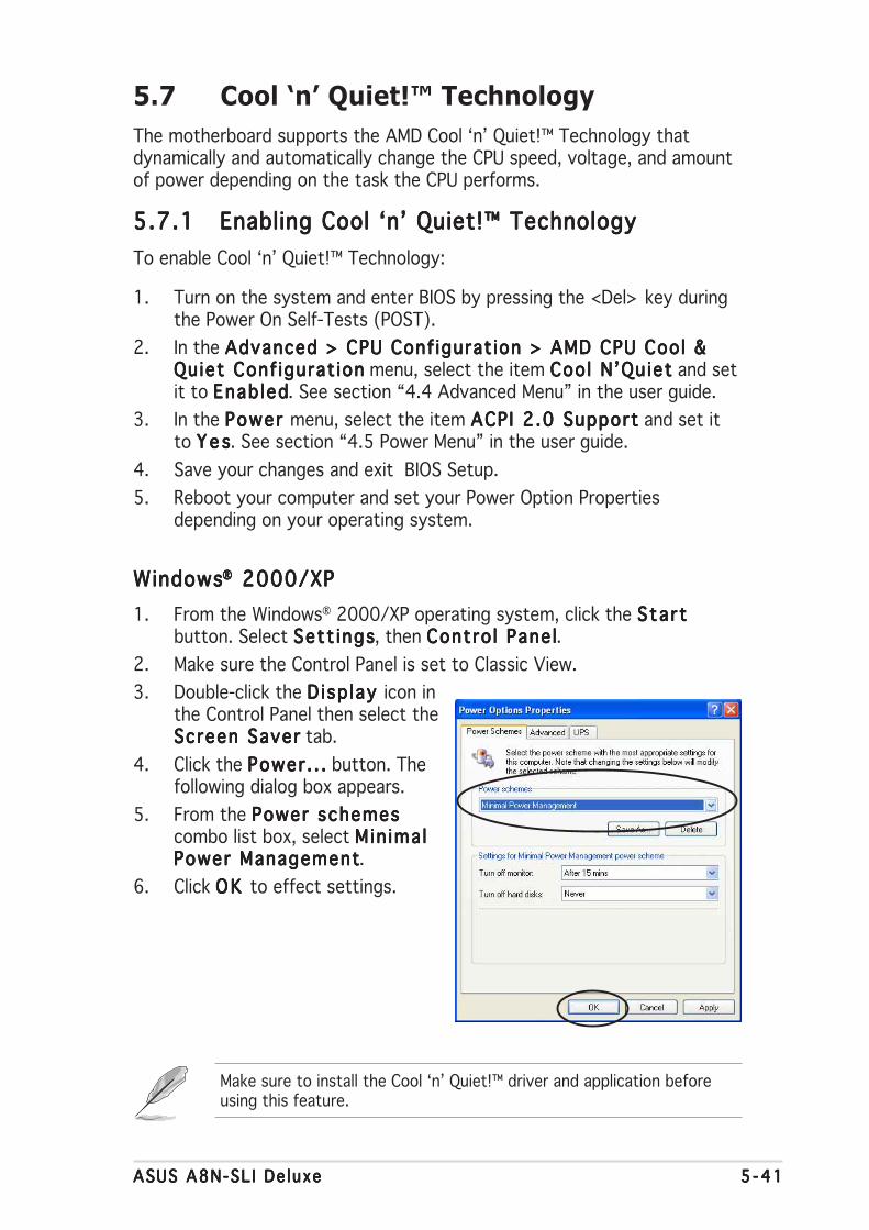
ASUS A8N-SL I De luxeASUS A8N-SL I De luxeASUS A8N-SL I De luxeASUS A8N-SL I De luxeASUS A8N-SL I De luxe 5 -415 -415 -415 -415 -41
5.7 Cool ‘n’ Quiet!™ Technology
The motherboard supports the AMD Cool ‘n’ Quiet!™ Technology thatdynamically and automatically change the CPU speed, voltage, and amountof power depending on the task the CPU performs.
5.7.15.7.15.7.15.7.15.7.1 Enabling Cool ‘n’ Quiet!™ TechnologyEnabling Cool ‘n’ Quiet!™ TechnologyEnabling Cool ‘n’ Quiet!™ TechnologyEnabling Cool ‘n’ Quiet!™ TechnologyEnabling Cool ‘n’ Quiet!™ Technology
To enable Cool ‘n’ Quiet!™ Technology:
1. Turn on the system and enter BIOS by pressing the <Del> key duringthe Power On Self-Tests (POST).
2. In the Advanced > CPU Conf igurat ion > AMD CPU Cool &Advanced > CPU Conf igurat ion > AMD CPU Cool &Advanced > CPU Conf igurat ion > AMD CPU Cool &Advanced > CPU Conf igurat ion > AMD CPU Cool &Advanced > CPU Conf igurat ion > AMD CPU Cool &Quiet Conf igurat ionQuiet Conf igurat ionQuiet Conf igurat ionQuiet Conf igurat ionQuiet Conf igurat ion menu, select the item Cool N’QuietCool N’QuietCool N’QuietCool N’QuietCool N’Quiet and setit to Enab ledEnab ledEnab ledEnab ledEnab led. See section “4.4 Advanced Menu” in the user guide.
3. In the Power Power Power Power Power menu, select the item ACPI 2.0 SupportACPI 2.0 SupportACPI 2.0 SupportACPI 2.0 SupportACPI 2.0 Support and set itto Y e sY e sY e sY e sY e s. See section “4.5 Power Menu” in the user guide.
4. Save your changes and exit BIOS Setup.
5. Reboot your computer and set your Power Option Propertiesdepending on your operating system.
WindowsWindowsWindowsWindowsWindows®®®®® 2000/XP 2000/XP 2000/XP 2000/XP 2000/XP
1. From the Windows® 2000/XP operating system, click the Sta r tSta r tSta r tSta r tSta r tbutton. Select Sett ingsSett ingsSett ingsSett ingsSett ings, then Contro l Pane lContro l Pane lContro l Pane lContro l Pane lContro l Pane l.
2. Make sure the Control Panel is set to Classic View.
3. Double-click the D isp lay D isp lay D isp lay D isp lay D isp lay icon inthe Control Panel then select theScreen SaverScreen SaverScreen SaverScreen SaverScreen Saver tab.
4. Click the Power . . .Power . . .Power . . .Power . . .Power . . . button. Thefollowing dialog box appears.
5. From the Power schemesPower schemesPower schemesPower schemesPower schemescombo list box, select M in ima lM in ima lM in ima lM in ima lM in ima lPower ManagementPower ManagementPower ManagementPower ManagementPower Management.
6. Click OK OK OK OK OK to effect settings.
Make sure to install the Cool ‘n’ Quiet!™ driver and application beforeusing this feature.

5 -425 -425 -425 -425 -42 Chapter 5 : Software supportChapter 5 : Software supportChapter 5 : Software supportChapter 5 : Software supportChapter 5 : Software support
5.7.25.7.25.7.25.7.25.7.2 Launching the Cool ‘n’ Quiet!™ softwareLaunching the Cool ‘n’ Quiet!™ softwareLaunching the Cool ‘n’ Quiet!™ softwareLaunching the Cool ‘n’ Quiet!™ softwareLaunching the Cool ‘n’ Quiet!™ software
The motherboard support CD includes the Cool ‘n’ Quiet!™ software thatenables you to view your system’s real-time CPU Frequency and voltage.
To launch the Cool ‘n’ Quiet!™ program:
1. If you are using Windows® 98SE/ME/2000, click the Sta r tSta r tSta r tSta r tSta r t button.Select Programs > ASUS > Cool & Quiet > Cool & Quiet.Programs > ASUS > Cool & Quiet > Cool & Quiet.Programs > ASUS > Cool & Quiet > Cool & Quiet.Programs > ASUS > Cool & Quiet > Cool & Quiet.Programs > ASUS > Cool & Quiet > Cool & Quiet.
2. If you are using Windows® XP, click the Sta r tSta r tSta r tSta r tSta r t button. Select A l lA l lA l lA l lA l lPrograms > ASUS > Cool & Quiet > Cool & Quiet.Programs > ASUS > Cool & Quiet > Cool & Quiet.Programs > ASUS > Cool & Quiet > Cool & Quiet.Programs > ASUS > Cool & Quiet > Cool & Quiet.Programs > ASUS > Cool & Quiet > Cool & Quiet.
3. The Cool ‘n’ Quiet!™ technology screen appears and displays thecurrent CPU Frequency and CPU Voltage.
Make sure to install the Cool ‘n’ Quiet!™ software from the motherboardsupport CD. Refer to section “5.2.3 Utilities menu”, for details.

6This chapter tells how to installSLI-ready PCI Express graphics cards.
NVIDIA® SLI™technology
support
ASUS A8N-SLI DeluxeASUS A8N-SLI DeluxeASUS A8N-SLI DeluxeASUS A8N-SLI DeluxeASUS A8N-SLI Deluxe
Chapter summary
6.1 Overview............................................................................... 6-1
6.2 Dual graphics cards setup .................................................... 6-2
ASUS A8N-SL I De luxeASUS A8N-SL I De luxeASUS A8N-SL I De luxeASUS A8N-SL I De luxeASUS A8N-SL I De luxe 6 - 16 - 16 - 16 - 16 - 1
6.1 Overview
The motherboard supports the NVIDIA® SLI™ (Scalable Link Interface)technology that allows you to install two identical PCI Express™ x16graphics cards. Follow the installation procedures in this section.
RequirementsRequirementsRequirementsRequirementsRequirements
• You should have two identical SLI-ready graphics cards that areNVIDIA® certified.
• Visit the ASUS website (www.asus.com) for a list of qualifiedSLI-ready graphics cards for this motherboard.
• Make sure that your graphics card driver supports the NVIDIA SLItechnology. Download the latest driver from the NVIDIA website(www.nvidia.com).
• Make sure that your power supply unit (PSU) can provide at least theminimum power required by your system. See “8. ATX powerconnectors” on page 2-25 for details.
• The NVIDIA SLI technology supports Windows® XP™ operatingsystem only.
• Visit the NVIDIA website for the supported 3D applications and thelatest graphics card drivers.

6 - 26 - 26 - 26 - 26 - 2 Chapter 6 : NV ID IAChapter 6 : NV ID IAChapter 6 : NV ID IAChapter 6 : NV ID IAChapter 6 : NV ID IA®®®®® SL I™ techno logy support SL I™ techno logy support SL I™ techno logy support SL I™ techno logy support SL I™ techno logy support
2. Simultaneously push the retention clips outward to release the card.
Re ten t i on c l i pRe ten t i on c l i pRe ten t i on c l i pRe ten t i on c l i pRe ten t i on c l i p
P r e - i n s t a l l edP re - i n s t a l l edP re - i n s t a l l edP re - i n s t a l l edP re - i n s t a l l edASUS E ZASUS E ZASUS E ZASUS E ZA S U S E Z
se l e c to r c a rdse l e c to r c a rdse l e c to r c a rdse l e c to r c a rdse l e c to r c a rd
A S U S E ZA S U S E ZA S U S E ZA S U S E ZA S U S E Zse l e c to r c a rdse l e c to r c a rdse l e c to r c a rdse l e c to r c a rdse l e c to r c a rd
6.2 Dual graphics card setup
6.2.16.2.16.2.16.2.16.2.1 Setting the ASUS EZ selector cardSetting the ASUS EZ selector cardSetting the ASUS EZ selector cardSetting the ASUS EZ selector cardSetting the ASUS EZ selector card
Your motherboard package comes with a pre-installedASUS EZ selector card. By default, the card is set fora single graphics card. To use two graphics cards onthis motherboard, you must first set the selector cardto Dual V ideo CardsDual V ideo CardsDual V ideo CardsDual V ideo CardsDual V ideo Cards.
To set the selector card:
1. Locate the selector card on the motherboard.
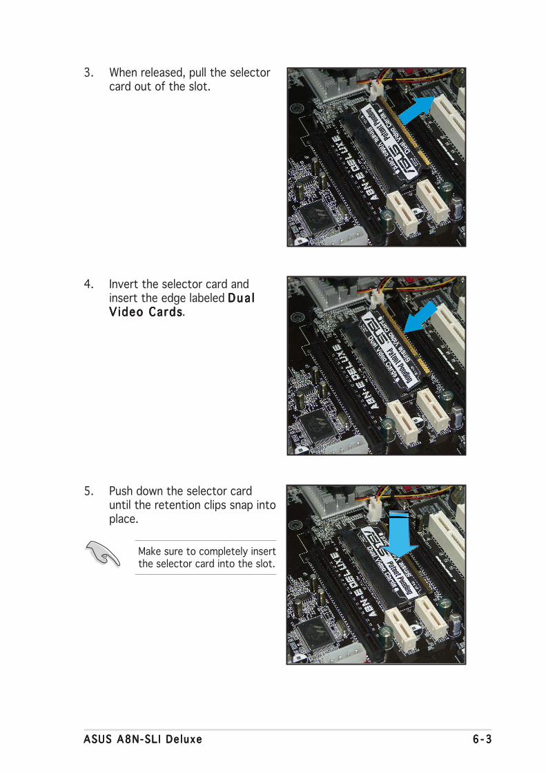
ASUS A8N-SL I De luxeASUS A8N-SL I De luxeASUS A8N-SL I De luxeASUS A8N-SL I De luxeASUS A8N-SL I De luxe 6 - 36 - 36 - 36 - 36 - 3
3. When released, pull the selectorcard out of the slot.
4. Invert the selector card andinsert the edge labeled Dua lDua lDua lDua lDua lV ideo CardsVideo CardsVideo CardsVideo CardsVideo Cards.
5. Push down the selector carduntil the retention clips snap intoplace.
Make sure to completely insertthe selector card into the slot.

6 - 46 - 46 - 46 - 46 - 4 Chapter 6 : NV ID IAChapter 6 : NV ID IAChapter 6 : NV ID IAChapter 6 : NV ID IAChapter 6 : NV ID IA®®®®® SL I™ techno logy support SL I™ techno logy support SL I™ techno logy support SL I™ techno logy support SL I™ techno logy support
6.2.26.2.26.2.26.2.26.2.2 Installing SLI-ready graphics cardsInstalling SLI-ready graphics cardsInstalling SLI-ready graphics cardsInstalling SLI-ready graphics cardsInstalling SLI-ready graphics cards
Go ld f i nge r sGo l d f i nge r sGo l d f i nge r sGo l d f i nge r sGo l d f i nge r s
Install only identical SLI-ready graphics cards that are NVIDIA® certified.Different types of graphics cards will not work together properly.
To install the graphics cards:
1. Prepare two graphics cards. Each graphics card should havegoldfingers for the SLI connector.
2. Remove the metal bracket covers opposite the two PCI Express x16slots.
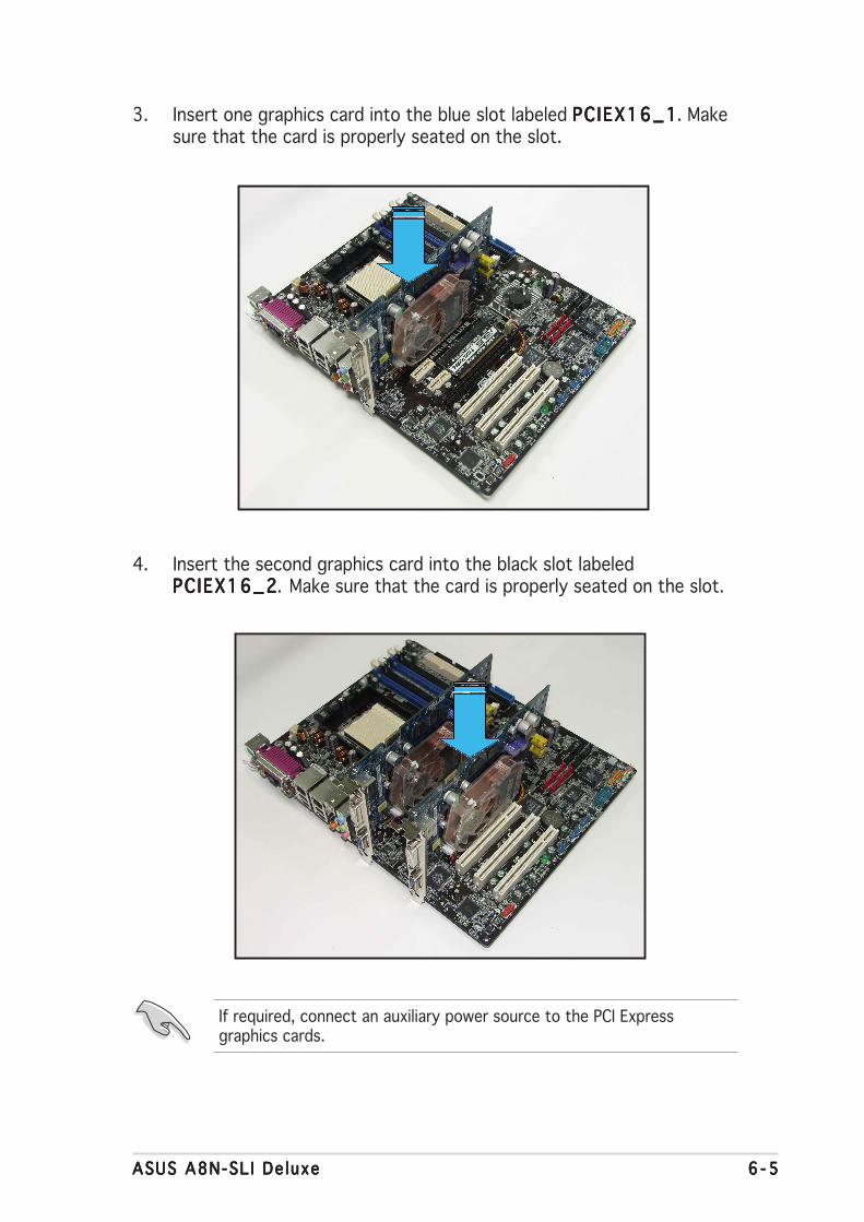
ASUS A8N-SL I De luxeASUS A8N-SL I De luxeASUS A8N-SL I De luxeASUS A8N-SL I De luxeASUS A8N-SL I De luxe 6 - 56 - 56 - 56 - 56 - 5
4. Insert the second graphics card into the black slot labeledPCIEX16_2PCIEX16_2PCIEX16_2PCIEX16_2PCIEX16_2. Make sure that the card is properly seated on the slot.
If required, connect an auxiliary power source to the PCI Expressgraphics cards.
3. Insert one graphics card into the blue slot labeled PC IEX16_1PCIEX16_1PCIEX16_1PCIEX16_1PCIEX16_1. Makesure that the card is properly seated on the slot.
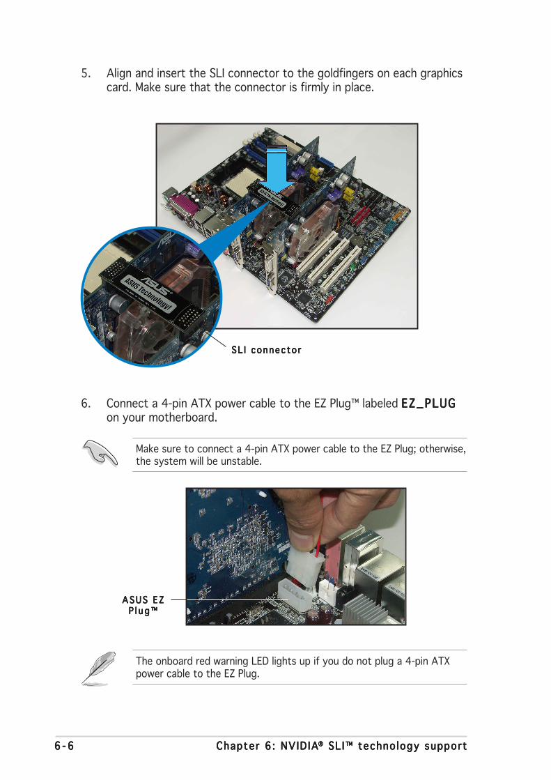
6 - 66 - 66 - 66 - 66 - 6 Chapter 6 : NV ID IAChapter 6 : NV ID IAChapter 6 : NV ID IAChapter 6 : NV ID IAChapter 6 : NV ID IA®®®®® SL I™ techno logy support SL I™ techno logy support SL I™ techno logy support SL I™ techno logy support SL I™ techno logy support
5. Align and insert the SLI connector to the goldfingers on each graphicscard. Make sure that the connector is firmly in place.
6. Connect a 4-pin ATX power cable to the EZ Plug™ labeled EZ_PLUGEZ_PLUGEZ_PLUGEZ_PLUGEZ_PLUGon your motherboard.
The onboard red warning LED lights up if you do not plug a 4-pin ATXpower cable to the EZ Plug.
SL I connec to rSL I connec to rSL I connec to rSL I connec to rSL I connec to r
Make sure to connect a 4-pin ATX power cable to the EZ Plug; otherwise,the system will be unstable.
ASUS E ZASUS E ZASUS E ZASUS E ZASUS E ZP l u g ™P l u g ™P l u g ™P l u g ™P l u g ™
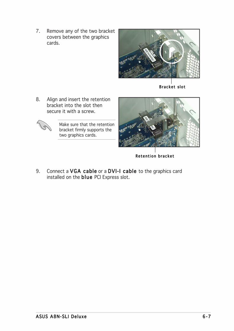
ASUS A8N-SL I De luxeASUS A8N-SL I De luxeASUS A8N-SL I De luxeASUS A8N-SL I De luxeASUS A8N-SL I De luxe 6 - 76 - 76 - 76 - 76 - 7
7. Remove any of the two bracketcovers between the graphicscards.
Reten t i on b r acke tRe ten t i on b r acke tRe ten t i on b r acke tRe ten t i on b r acke tRe ten t i on b r acke t
B r acke t s l o tB r acke t s l o tB r acke t s l o tB r acke t s l o tB r acke t s l o t
9. Connect a VGA cab leVGA cab leVGA cab leVGA cab leVGA cab le or a DVI- I cab le DVI- I cab le DVI- I cab le DVI- I cab le DVI- I cab le to the graphics cardinstalled on the b lue b lue b lue b lue b lue PCI Express slot.
8. Align and insert the retentionbracket into the slot thensecure it with a screw.
Make sure that the retentionbracket firmly supports thetwo graphics cards.

6 - 86 - 86 - 86 - 86 - 8 Chapter 6 : NV ID IAChapter 6 : NV ID IAChapter 6 : NV ID IAChapter 6 : NV ID IAChapter 6 : NV ID IA®®®®® SL I™ techno logy support SL I™ techno logy support SL I™ techno logy support SL I™ techno logy support SL I™ techno logy support
NV ID IA Se t t i ngs i conNV ID IA Se t t i ngs i conNV ID IA Se t t i ngs i conNV ID IA Se t t i ngs i conNV ID IA Se t t i ngs i con
To enable the multi-GPU feature:
1. Click the NVIDIA Sett ingsNVIDIA Sett ingsNVIDIA Sett ingsNVIDIA Sett ingsNVIDIA Sett ingsi coni coni coni coni con on your Windows taskbar.
2. From the pop-up menu, selectnView Desktop ManagernView Desktop ManagernView Desktop ManagernView Desktop ManagernView Desktop Managerthen click nView Propert ies nView Propert ies nView Propert ies nView Propert ies nView Propert ies.
Make sure that your PCI Express graphics card driver supports theNVIDIA SLI technology. Download the latest driver from the NVIDIAwebsite (www.nvidia.com).
6.2.36.2.36.2.36.2.36.2.3 Setting the SLI mode in BIOSSetting the SLI mode in BIOSSetting the SLI mode in BIOSSetting the SLI mode in BIOSSetting the SLI mode in BIOS
By default, the SLI mode item in the BIOS is set to [Auto]. This allows theBIOS to automatically detect the SLI selector card setting on themotherboard.
6.2.46.2.46.2.46.2.46.2.4 Installing the device driversInstalling the device driversInstalling the device driversInstalling the device driversInstalling the device drivers
Refer to the documentation that came with your graphics card package toinstall the device drivers.
• We recommend that you keep the SLI mode item setting to [Auto].
• When not set to [Auto], make sure that the SLI mode BIOS settingis the same as the EZ selector card setting.
• See section “4.4.9 SLI mode” on page 4-34 for details.
6.2.56.2.56.2.56.2.56.2.5 Enabling the multi-GPU feature in WindowsEnabling the multi-GPU feature in WindowsEnabling the multi-GPU feature in WindowsEnabling the multi-GPU feature in WindowsEnabling the multi-GPU feature in Windows
After installing your graphics cards and the device drivers, enable theMulti-Graphics Processing Unit (GPU) feature in the NVIDIA nViewproperties.

ASUS A8N-SL I De luxeASUS A8N-SL I De luxeASUS A8N-SL I De luxeASUS A8N-SL I De luxeASUS A8N-SL I De luxe 6 - 96 - 96 - 96 - 96 - 9
3. From the nView Desktop Managerwindow, select the D e s k t o pD e s k t o pD e s k t o pD e s k t o pD e s k t o pManagement Management Management Management Management tab.
4. Click Propert iesPropert iesPropert iesPropert iesPropert ies to display theDisplay Properties dialog box.
5. From the Display Propertiesdialog box, select the Sett ingsSett ingsSett ingsSett ingsSett ingstab then click AdvancedAdvancedAdvancedAdvancedAdvanced.
6. Select the NVIDIA GeForceNVIDIA GeForceNVIDIA GeForceNVIDIA GeForceNVIDIA GeForcetab.
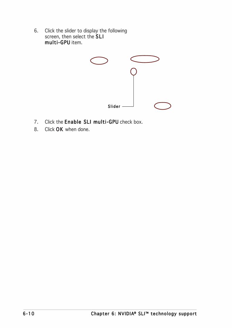
6 -106 -106 -106 -106 -10 Chapter 6 : NV ID IAChapter 6 : NV ID IAChapter 6 : NV ID IAChapter 6 : NV ID IAChapter 6 : NV ID IA®®®®® SL I™ techno logy support SL I™ techno logy support SL I™ techno logy support SL I™ techno logy support SL I™ techno logy support
6. Click the slider to display the followingscreen, then select the S L IS L IS L IS L IS L Imult i -GPUmult i -GPUmult i -GPUmult i -GPUmult i -GPU item.
7. Click the Enable SLI mult i -GPUEnable SLI mult i -GPUEnable SLI mult i -GPUEnable SLI mult i -GPUEnable SLI mult i -GPU check box.
8. Click O K O K O K O K O K when done.
S l i d e rS l i d e rS l i d e rS l i d e rS l i d e r

Appendix
This chapter describes the contentsof the support CD that comes withthe motherboard package.

ASUS A8N-SLI DeluxeASUS A8N-SLI DeluxeASUS A8N-SLI DeluxeASUS A8N-SLI DeluxeASUS A8N-SLI Deluxe
Chapter summary
A.1 Using the SATA extension module ....................................... A-1
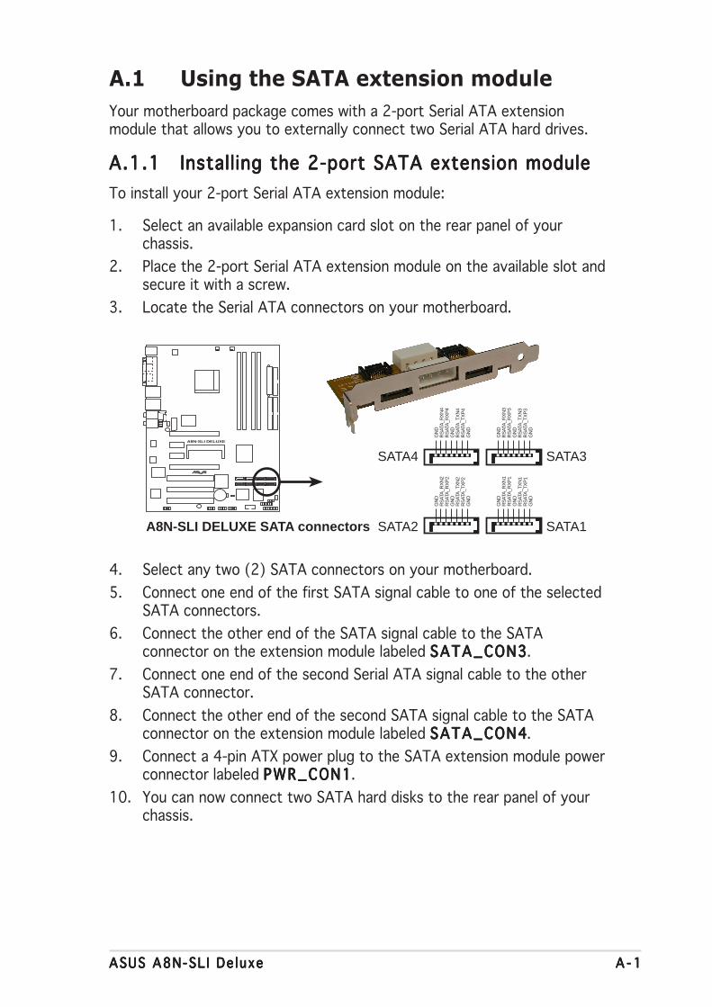
ASUS A8N-SL I De luxeASUS A8N-SL I De luxeASUS A8N-SL I De luxeASUS A8N-SL I De luxeASUS A8N-SL I De luxe A - 1A - 1A - 1A - 1A - 1
A.1 Using the SATA extension module
Your motherboard package comes with a 2-port Serial ATA extensionmodule that allows you to externally connect two Serial ATA hard drives.
A.1.1A.1.1A.1.1A.1.1A.1.1 Installing the 2-port SATA extension moduleInstalling the 2-port SATA extension moduleInstalling the 2-port SATA extension moduleInstalling the 2-port SATA extension moduleInstalling the 2-port SATA extension module
To install your 2-port Serial ATA extension module:
1. Select an available expansion card slot on the rear panel of yourchassis.
2. Place the 2-port Serial ATA extension module on the available slot andsecure it with a screw.
3. Locate the Serial ATA connectors on your motherboard.
4. Select any two (2) SATA connectors on your motherboard.
5. Connect one end of the first SATA signal cable to one of the selectedSATA connectors.
6. Connect the other end of the SATA signal cable to the SATAconnector on the extension module labeled SATA_CON3SATA_CON3SATA_CON3SATA_CON3SATA_CON3.
7. Connect one end of the second Serial ATA signal cable to the otherSATA connector.
8. Connect the other end of the second SATA signal cable to the SATAconnector on the extension module labeled SATA_CON4SATA_CON4SATA_CON4SATA_CON4SATA_CON4.
9. Connect a 4-pin ATX power plug to the SATA extension module powerconnector labeled PWR_CON1PWR_CON1PWR_CON1PWR_CON1PWR_CON1.
10. You can now connect two SATA hard disks to the rear panel of yourchassis.
A8N-SLI DELUXE
®
A8N-SLI DELUXE SATA connectors SATA1SATA2
GN
DR
SAT
A_T
XP
4R
SAT
A_T
XN
4G
ND
RS
ATA
_RX
P4
RS
ATA
_RX
N4
GN
D
GN
DR
SAT
A_T
XP
3R
SAT
A_T
XN
3G
ND
RS
ATA
_RX
P3
RS
ATA
_RX
N3
GN
D
GN
DR
SAT
A_T
XP
2R
SAT
A_T
XN
2G
ND
RS
ATA
_RX
P2
RS
ATA
_RX
N2
GN
D
GN
DR
SAT
A_T
XP
1R
SAT
A_T
XN
1G
ND
RS
ATA
_RX
P1
RS
ATA
_RX
N1
GN
D
SATA3SATA4
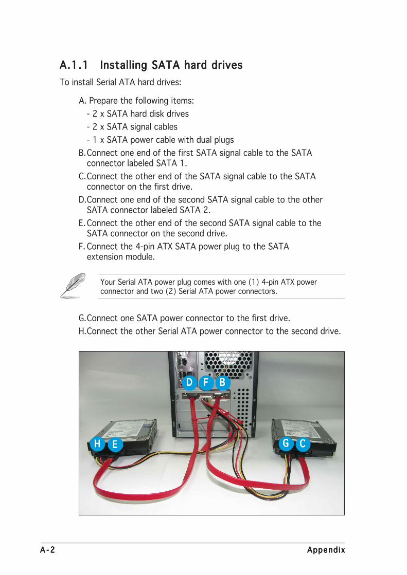
A - 2A - 2A - 2A - 2A - 2 Append i xAppend i xAppend i xAppend i xAppend i x
A.1.1A.1.1A.1.1A.1.1A.1.1 Installing SATA hard drivesInstalling SATA hard drivesInstalling SATA hard drivesInstalling SATA hard drivesInstalling SATA hard drives
To install Serial ATA hard drives:
A. Prepare the following items:
- 2 x SATA hard disk drives
- 2 x SATA signal cables
- 1 x SATA power cable with dual plugs
B.Connect one end of the first SATA signal cable to the SATAconnector labeled SATA 1.
C.Connect the other end of the SATA signal cable to the SATAconnector on the first drive.
D.Connect one end of the second SATA signal cable to the otherSATA connector labeled SATA 2.
E. Connect the other end of the second SATA signal cable to theSATA connector on the second drive.
F. Connect the 4-pin ATX SATA power plug to the SATAextension module.
Your Serial ATA power plug comes with one (1) 4-pin ATX powerconnector and two (2) Serial ATA power connectors.
G.Connect one SATA power connector to the first drive.
H.Connect the other Serial ATA power connector to the second drive.
DDDDD FFFFF BBBBB
HHHHH EEEEE GGGGG CCCCC