Embed Size (px)
Citation preview
(English) DM-RAFC001-02
Dealer's Manual
ROAD MTB Trekking
City Touring/Comfort Bike
URBAN SPORT E-BIKE
Front Chainwheel
DURA-ACEFC-R9100
ULTEGRAFC-R8000
Bottom bracketBB-R9100SM-BBR60SM-BB92-41BSM-BB72-41B
2
CONTENTS
IMPORTANT NOTICE .............................................................................................. 3
TO ENSURE SAFETY ............................................................................................... 4
LIST OF TOOLS TO BE USED .................................................................................. 8BB-R9100 .......................................................................................................................................................8
SM-BBR60 ......................................................................................................................................................8
SM-BB92-41B/SM-BB72-41B .........................................................................................................................9
INSTALLATION ..................................................................................................... 11Threaded bottom bracket (HOLLOWTECH II) ...........................................................................................11
PRESS-FIT BB ...............................................................................................................................................14
Installation of the crank ............................................................................................................................17
MAINTENANCE .................................................................................................... 20Replacing chainrings ..................................................................................................................................20
3
IMPORTANT NOTICE
IMPORTANT NOTICE
• This dealer's manual is intended primarily for use by professional bicycle mechanics. Users who are not professionally trained for bicycle assembly should not attempt to install the components themselves using the dealer's manuals. If any part of the information on the manual is unclear to you, do not proceed with the installation. Instead, contact your place of purchase or a local bicycle dealer for their assistance.
• Make sure to read all instruction manuals included with the product.
• Do not disassemble or modify the product other than as stated in the information contained in this dealer's manual.
• All dealer's manuals and instruction manuals can be viewed on-line on our website (http://si.shimano.com).
• Please observe the appropriate rules and regulations of the country, state or region in which you conduct your business as a dealer.
For safety, be sure to read this dealer's manual thoroughly before use, and follow it for correct use.
The following instructions must be observed at all times in order to prevent personal injury and physical damage to equipment and surroundings.The instructions are classified according to the degree of danger or damage which may occur if the product is used incorrectly.
DANGER
Failure to follow the instructions will result in death or serious injury.
WARNING
Failure to follow the instructions could result in death or serious injury.
CAUTION
Failure to follow the instructions could cause personal injury or physical damage to equipment and surroundings.
4
TO ENSURE SAFETY
TO ENSURE SAFETY
WARNING
• Be sure to follow the instructions provided in the manuals when installing the product.It is recommended to use genuine Shimano parts only. If parts such as bolts and nuts become loose or damaged, the bicycle may suddenly fall over, which may cause serious injury. In addition, if adjustments are not carried out correctly, problems may occur, and the bicycle may suddenly fall over, which may cause serious injury.
• Be sure to wear safety glasses or goggles to protect your eyes while performing maintenance tasks such as replacing parts.
• After reading the dealer's manual thoroughly, keep it in a safe place for later reference.
Be sure to also inform users of the following: • Intervals between maintenance depend on the use and riding circumstances. Clean the chain with an appropriate chain cleaner regularly. Never use alkali based or acid based solvents, such as rust cleaners. If those solvent be used chain might break and cause serious injury.
• Check that there are no cracks in the crank arms before riding the bicycle. If there are any cracks, the crank arm may break and you may fall off the bicycle.
• Be careful not to let the hemming of your clothes get caught in the chain while riding. Otherwise you may fall off the bicycle.
• Check the chain for any damage (deformation or crack), skipping, or other abnormalities such as unintended gear shifting. If any problems are found, consult a dealer or an agency. The chain may break, and you may fall.
For Installation to the Bicycle, and Maintenance: • If the inner cover is not installed correctly, the axle may rust and become damaged, and the bicycle may fall over and serious injury may occur as a result.
• The two left crank arm mounting bolts should be tightened in stages rather than fully tightened at once. Use a torque wrench to check that the final tightening torques are within the range of 12 - 14 N·m. Furthermore, after riding approximately 100km (60 miles), use a torque wrench to re-check the tightening torques. It is also important to periodically check the tightening torques. If the tightening torques are too weak or if the mounting bolts are not tightened alternately in stages, the left crank arm may come off and the bicycle may fall over, and serious injury may occur as a result.
CAUTION
Be sure to also inform users of the following: • Be careful to keep body parts away from the sharp teeth of chainrings.
5
TO ENSURE SAFETY
NOTE
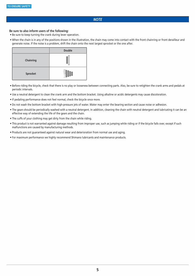
Be sure to also inform users of the following: • Be sure to keep turning the crank during lever operation.
• When the chain is in any of the positions shown in the illustration, the chain may come into contact with the front chainring or front derailleur and generate noise. If the noise is a problem, shift the chain onto the next largest sprocket or the one after.
Double
Chainring
Sprocket
• Before riding the bicycle, check that there is no play or looseness between connecting parts. Also, be sure to retighten the crank arms and pedals at periodic intervals.
• Use a neutral detergent to clean the crank arm and the bottom bracket. Using alkaline or acidic detergents may cause discoloration.
• If pedaling performance does not feel normal, check the bicycle once more.
• Do not wash the bottom bracket with high-pressure jets of water. Water may enter the bearing section and cause noise or adhesion.
• The gears should be periodically washed with a neutral detergent. In addition, cleaning the chain with neutral detergent and lubricating it can be an effective way of extending the life of the gears and the chain.
• The cuffs of your clothing may get dirty from the chain while riding.
• This product is not warranted against damage resulting from improper use, such as jumping while riding or if the bicycle falls over, except if such malfunctions are caused by manufacturing methods.
• Products are not guaranteed against natural wear and deterioration from normal use and aging.
• For maximum performance we highly recommend Shimano lubricants and maintenance products.
6
TO ENSURE SAFETY
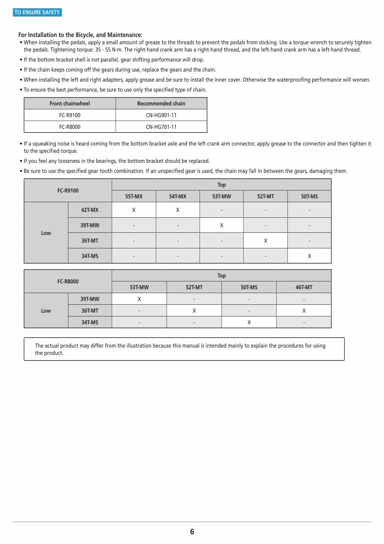
For Installation to the Bicycle, and Maintenance: • When installing the pedals, apply a small amount of grease to the threads to prevent the pedals from sticking. Use a torque wrench to securely tighten the pedals. Tightening torque: 35 - 55 N·m. The right-hand crank arm has a right-hand thread, and the left-hand crank arm has a left-hand thread.
• If the bottom bracket shell is not parallel, gear shifting performance will drop.
• If the chain keeps coming off the gears during use, replace the gears and the chain.
• When installing the left and right adapters, apply grease and be sure to install the inner cover. Otherwise the waterproofing performance will worsen.
• To ensure the best performance, be sure to use only the specified type of chain.
Front chainwheel Recommended chain
FC-R9100 CN-HG901-11
FC-R8000 CN-HG701-11
• If a squeaking noise is heard coming from the bottom bracket axle and the left crank arm connector, apply grease to the connector and then tighten it to the specified torque.
• If you feel any looseness in the bearings, the bottom bracket should be replaced.
• Be sure to use the specified gear tooth combination. If an unspecified gear is used, the chain may fall in between the gears, damaging them.
FC-R9100Top
55T-MX 54T-MX 53T-MW 52T-MT 50T-MS
Low
42T-MX X X - - -
39T-MW - - X - -
36T-MT - - - X -
34T-MS - - - - X
FC-R8000Top
53T-MW 52T-MT 50T-MS 46T-MT
Low
39T-MW X - - -
36T-MT - X - X
34T-MS - - X -
The actual product may differ from the illustration because this manual is intended mainly to explain the procedures for using the product.
LIST OF TOOLS TO BE USED
8
LIST OF TOOLS TO BE USED
LIST OF TOOLS TO BE USED
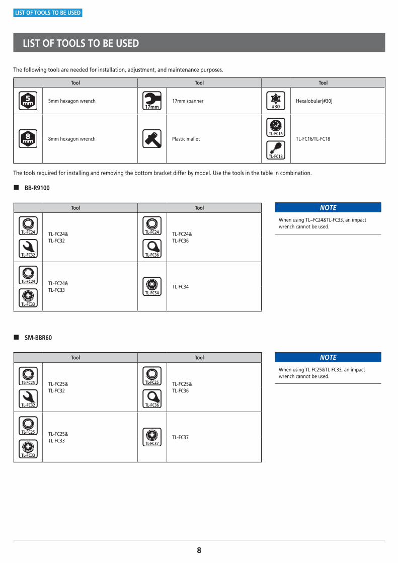
The following tools are needed for installation, adjustment, and maintenance purposes.
Tool Tool Tool
5mm hexagon wrench 17mm spanner Hexalobular[#30]
8mm hexagon wrench Plastic mallet TL-FC16/TL-FC18
The tools required for installing and removing the bottom bracket differ by model. Use the tools in the table in combination.
� BB-R9100
Tool Tool
TL-FC24& TL-FC32
TL-FC24& TL-FC36
TL-FC24& TL-FC33
TL-FC34
NOTE
When using TL−FC24&TL-FC33, an impact wrench cannot be used.
� SM-BBR60
Tool Tool
TL-FC25&TL-FC32
TL-FC25&TL-FC36
TL-FC25&TL-FC33
TL-FC37
NOTE
When using TL-FC25&TL-FC33, an impact wrench cannot be used.
9
LIST OF TOOLS TO BE USED
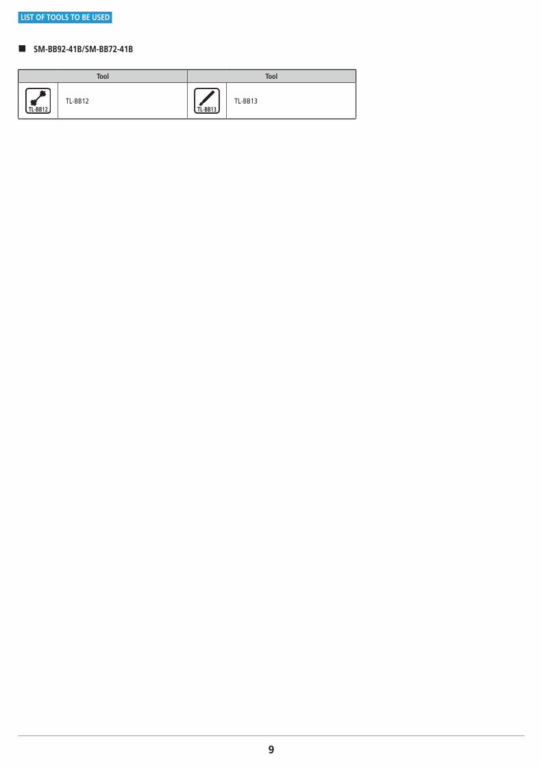
� SM-BB92-41B/SM-BB72-41B
Tool Tool
TL-BB12 TL-BB13
INSTALLATION
11
INSTALLATION
Threaded bottom bracket (HOLLOWTECH II)
INSTALLATION
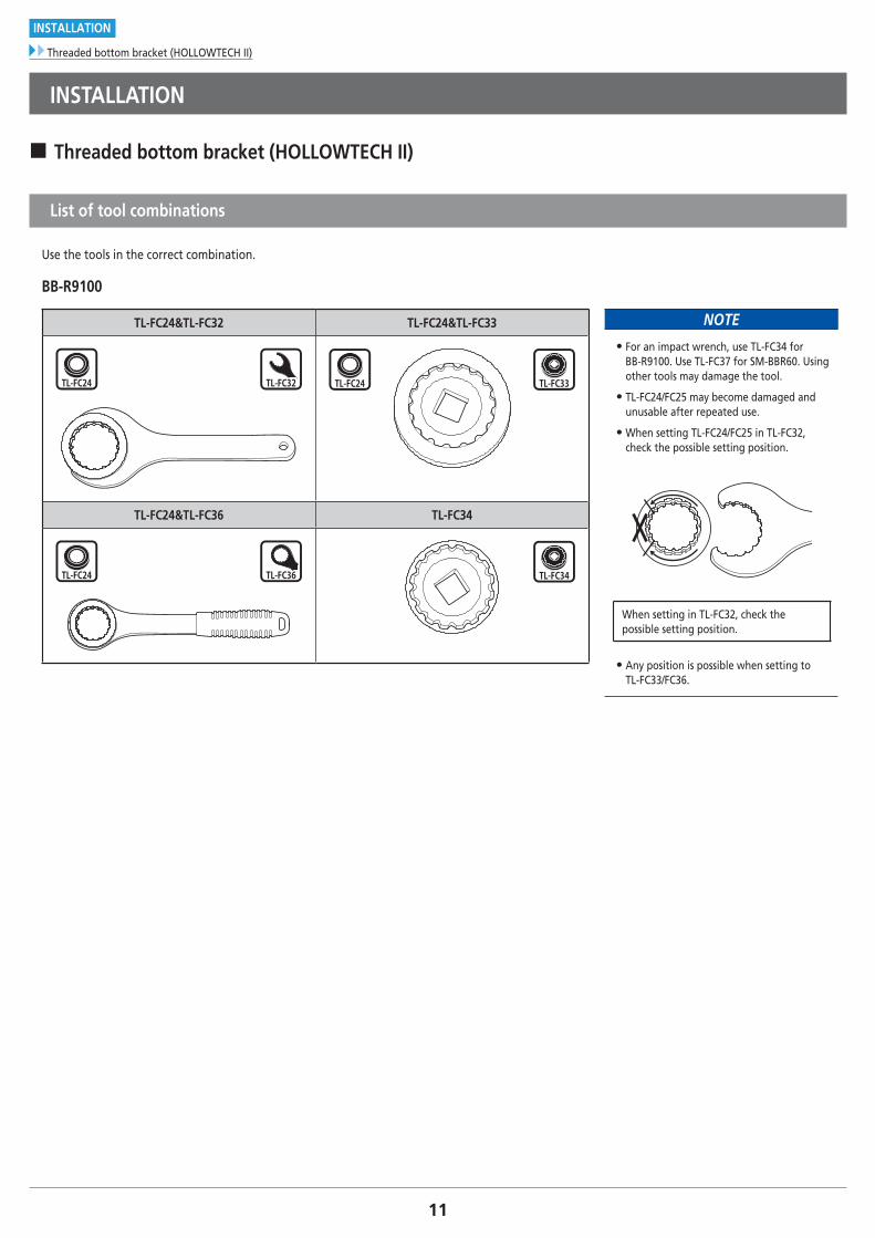
� Threaded bottom bracket (HOLLOWTECH II)
List of tool combinations
Use the tools in the correct combination.
BB-R9100
TL-FC24&TL-FC32 TL-FC24&TL-FC33
TL-FC24&TL-FC36 TL-FC34
NOTE
• For an impact wrench, use TL-FC34 for BB-R9100. Use TL-FC37 for SM-BBR60. Using other tools may damage the tool.
• TL-FC24/FC25 may become damaged and unusable after repeated use.
• When setting TL-FC24/FC25 in TL-FC32, check the possible setting position.
When setting in TL-FC32, check the possible setting position.
• Any position is possible when setting to TL-FC33/FC36.
12
INSTALLATION
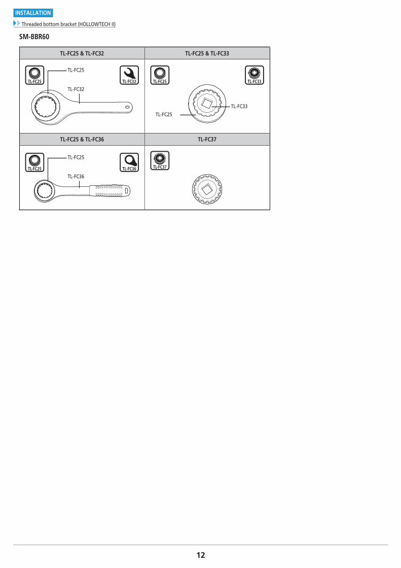
Threaded bottom bracket (HOLLOWTECH II)
SM-BBR60
TL-FC25 & TL-FC32 TL-FC25 & TL-FC33
TL-FC25
TL-FC32
TL-FC33
TL-FC25
TL-FC25 & TL-FC36 TL-FC37
TL-FC25
TL-FC36
13
INSTALLATION
Threaded bottom bracket (HOLLOWTECH II)
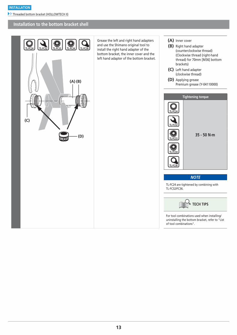
Installation to the bottom bracket shell
(C)
(D)
(A) (B)
Grease the left and right hand adapters and use the Shimano original tool to install the right hand adapter of the bottom bracket, the inner cover and the left hand adapter of the bottom bracket.
(A) Inner cover
(B) Right hand adapter (counterclockwise thread) (Clockwise thread (right-hand thread) for 70mm [M36] bottom brackets)
(C) Left hand adapter (clockwise thread)
(D) Applying grease Premium grease (Y-04110000)
Tightening torque
35 - 50 N·m
NOTE
TL-FC24 are tightened by combining with TL-FC32/FC36.
TECH TIPS
For tool combinations used when installing/uninstalling the bottom bracket, refer to "List of tool combinations".
14
INSTALLATION
PRESS-FIT BB
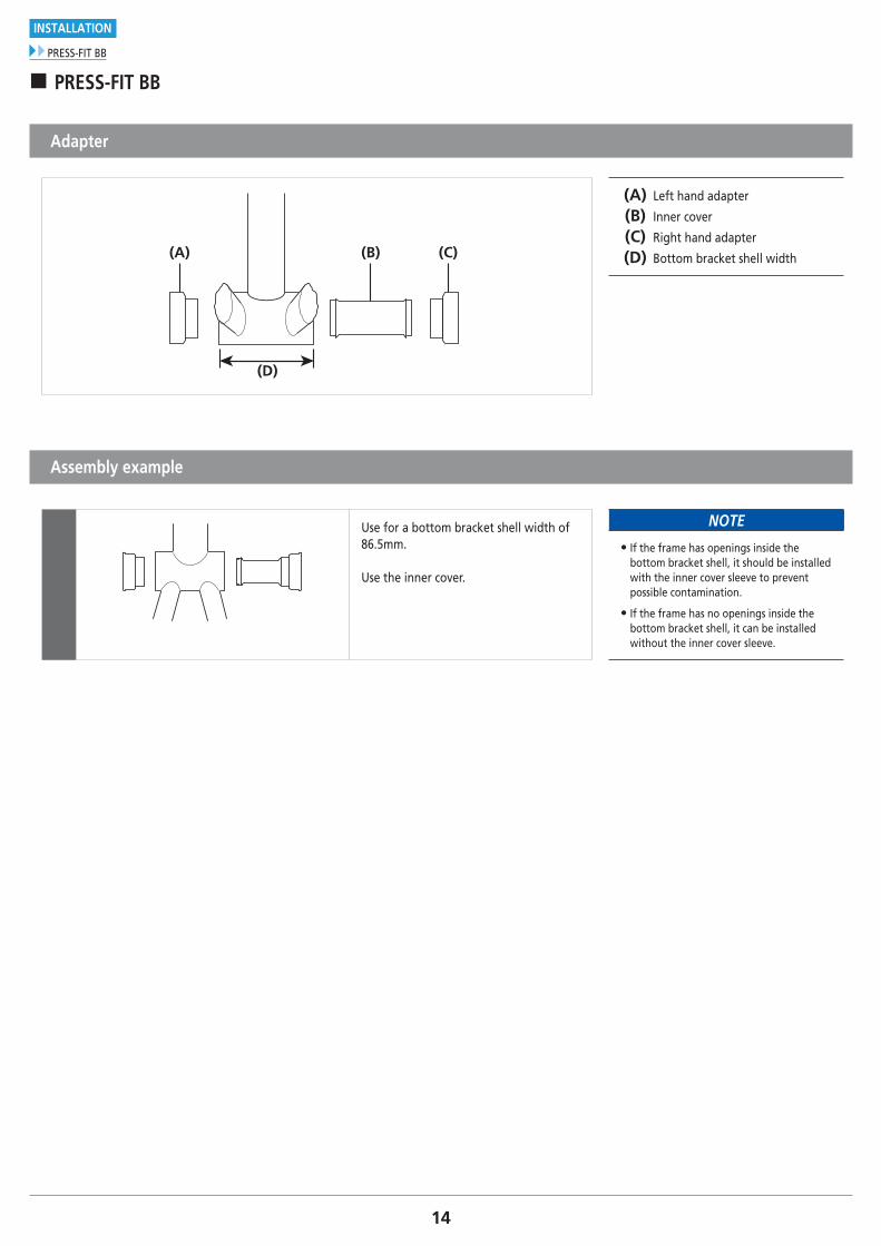
� PRESS-FIT BB
Adapter
(A) (C)(B)
(D)
(A) Left hand adapter
(B) Inner cover
(C) Right hand adapter
(D) Bottom bracket shell width
Assembly example
Use for a bottom bracket shell width of 86.5mm.
Use the inner cover.
NOTE
• If the frame has openings inside the bottom bracket shell, it should be installed with the inner cover sleeve to prevent possible contamination.
• If the frame has no openings inside the bottom bracket shell, it can be installed without the inner cover sleeve.
15
INSTALLATION
PRESS-FIT BB
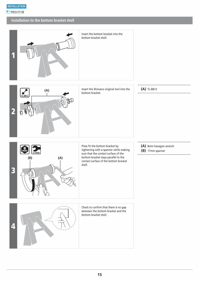
Installation to the bottom bracket shell
1
Insert the bottom bracket into the bottom bracket shell.
2
(A) Insert the Shimano original tool into the bottom bracket.
(A) TL-BB12
3
(A)(B)
Press fit the bottom bracket by tightening with a spanner while making sure that the contact surface of the bottom bracket stays parallel to the contact surface of the bottom bracket shell.
(A) 8mm hexagon wrench
(B) 17mm spanner
4
Check to confirm that there is no gap between the bottom bracket and the bottom bracket shell.
16
INSTALLATION
PRESS-FIT BB
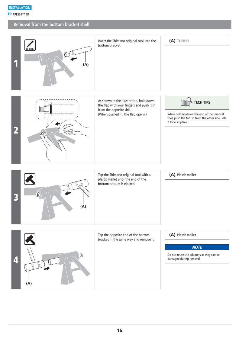
Removal from the bottom bracket shell
1 (A)
Insert the Shimano original tool into the bottom bracket.
(A) TL-BB13
2
As shown in the illustration, hold down the flap with your fingers and push it in from the opposite side. (When pushed in, the flap opens.)
TECH TIPS
While holding down the end of the removal tool, push the tool in from the other side until it locks in place.
3(A)
Tap the Shimano original tool with a plastic mallet until the end of the bottom bracket is ejected.
(A) Plastic mallet
4
(A)
Tap the opposite end of the bottom bracket in the same way and remove it.
(A) Plastic mallet
NOTE
Do not reuse the adapters as they can be damaged during removal.
17To be continued on next page
INSTALLATION
Installation of the crank
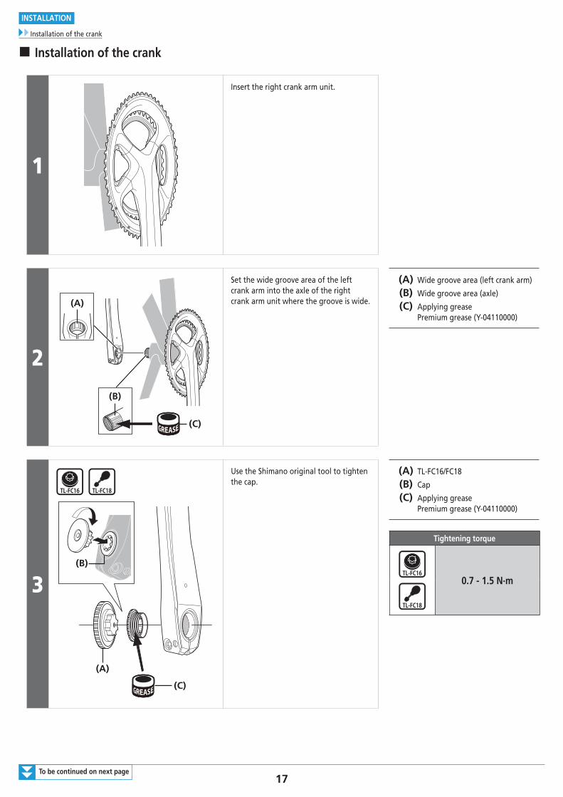
� Installation of the crank
1
Insert the right crank arm unit.
2
(C)
(B)
(A)
Set the wide groove area of the left crank arm into the axle of the right crank arm unit where the groove is wide.
(A) Wide groove area (left crank arm)
(B) Wide groove area (axle)
(C) Applying grease Premium grease (Y-04110000)
3
(A)
(C)
(B)
Use the Shimano original tool to tighten the cap.
(A) TL-FC16/FC18
(B) Cap
(C) Applying grease Premium grease (Y-04110000)
Tightening torque
0.7 - 1.5 N·m
18
INSTALLATION
Installation of the crank
4
(A)
(B)
(z)
(C)
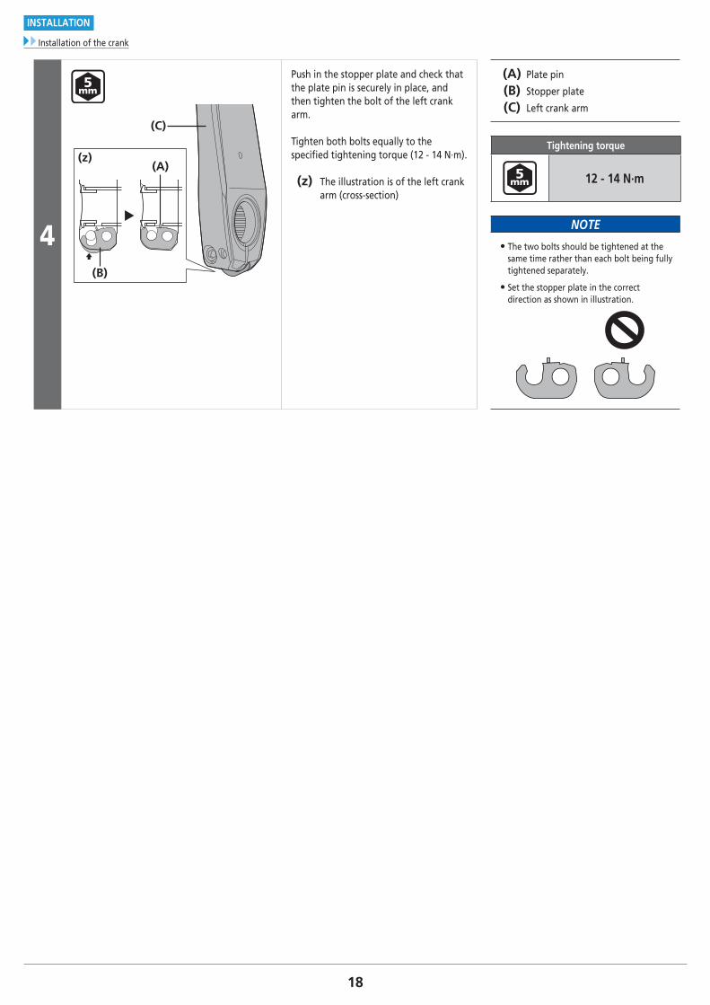
Push in the stopper plate and check that the plate pin is securely in place, and then tighten the bolt of the left crank arm.
Tighten both bolts equally to the specified tightening torque (12 - 14 N·m).
(z) The illustration is of the left crank arm (cross-section)
(A) Plate pin
(B) Stopper plate
(C) Left crank arm
Tightening torque
12 - 14 N·m
NOTE
• The two bolts should be tightened at the same time rather than each bolt being fully tightened separately.
• Set the stopper plate in the correct direction as shown in illustration.
MAINTENANCE
20
MAINTENANCE
Replacing chainrings
MAINTENANCE
� Replacing chainrings
NOTE
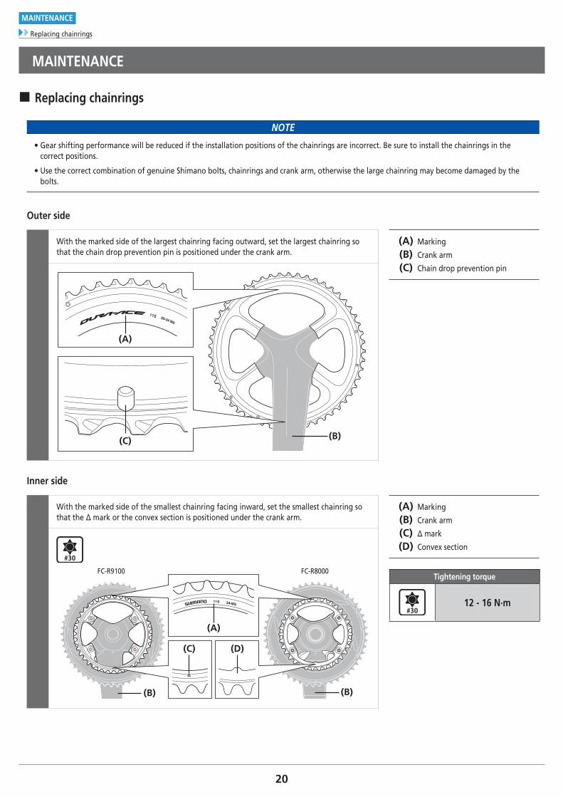
• Gear shifting performance will be reduced if the installation positions of the chainrings are incorrect. Be sure to install the chainrings in the correct positions.
• Use the correct combination of genuine Shimano bolts, chainrings and crank arm, otherwise the large chainring may become damaged by the bolts.
Outer side
With the marked side of the largest chainring facing outward, set the largest chainring so that the chain drop prevention pin is positioned under the crank arm.
(A) Marking
(B) Crank arm
(C) Chain drop prevention pin
(A)
(C) (B)
11S 50-34 MS
Inner side
With the marked side of the smallest chainring facing inward, set the smallest chainring so that the Δ mark or the convex section is positioned under the crank arm.
(A) Marking
(B) Crank arm
(C) Δ mark
(D) Convex section
Tightening torque
12 - 16 N·m
(B)(B)
11S -34 MS
(C)
(A)
(D)
FC-R9100 FC-R8000

Please note: specifications are subject to change for improvement without notice. (English) © Feb. 2017 by Shimano Inc. ITP