Embed Size (px)
Citation preview
IntroductionUse this document for quick installation and setup.
Frontline® X240TM is capable of capturing and demodulating all RF channels and packet types defined in all released Bluetooth specifications and beyond. The user is not required to specify the addresses of the devices to be captured or their roles (master or slave) during the connection lifetime. Prior to capturing the data the user does not need to enter any
information (PIN, OOB, long term key, link key) used to encrypt or decrypt data. X240TM provides live capture of all 79 Classic Bluetooth channels or 40 Bluetooth low energy channels storing data for both live and post-capture analysis. This quick start guide provides sufficient information to begin data capture. Detailed hardware and software information is contained in the Wireless Protocol Suite Hardware and Software User Manual. The manual is available on FTE.com.
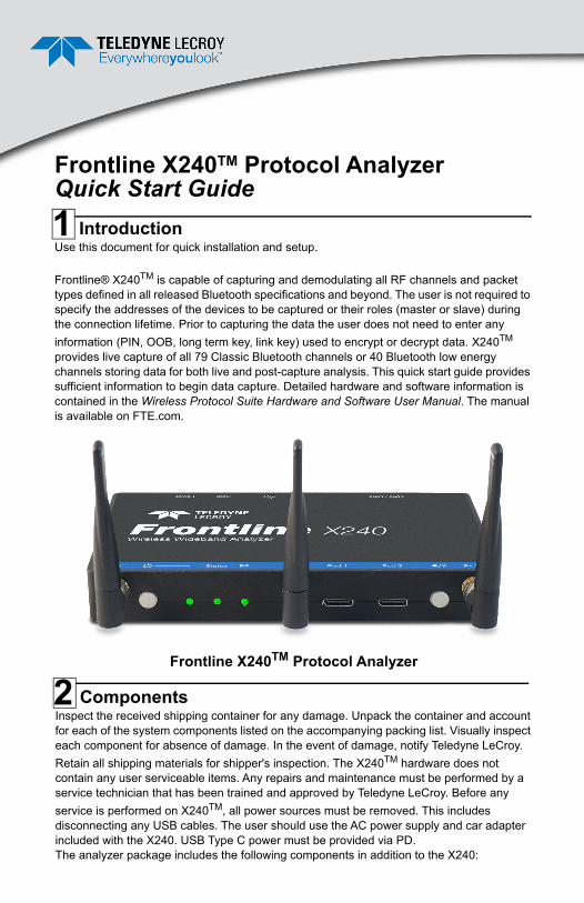
Frontline X240TM Protocol Analyzer
ComponentsInspect the received shipping container for any damage. Unpack the container and account for each of the system components listed on the accompanying packing list. Visually inspect each component for absence of damage. In the event of damage, notify Teledyne LeCroy.
Retain all shipping materials for shipper's inspection. The X240TM hardware does not contain any user serviceable items. Any repairs and maintenance must be performed by a service technician that has been trained and approved by Teledyne LeCroy. Before any
service is performed on X240TM, all power sources must be removed. This includes disconnecting any USB cables. The user should use the AC power supply and car adapter included with the X240. USB Type C power must be provided via PD. The analyzer package includes the following components in addition to the X240:
Frontline X240TM Protocol Analyzer Quick Start Guide
1
2
3 Computer System Requirements
Qty Description Qty Description
1 5V @ 3A PowerPort C 1 Type C PD Power Supply
1 6' Ethernet Cable, CAT 6 (1 Gbps), BLACK
2 3' USB 3.0 Type C to C cable 3 RF 2.45GHZ/5.3GHZ WHIP TILT Antenna
1 3' USB 3.0 Type C to A cable 1 USB Car Charger PD
Supported Systems • Operating System: Windows 10 • USB: USB 2.0 and laterMinimum Requirements • Processor: Core i5 at 2.7 GHz • RAM: 4 GB • Free Hard Disk Space on C: drive: 20
GB
Install Software • From Download: Download the latest
Wireless Protocol Suite installer from FTE.com. http://fte.com/x240-soft. Once downloaded, double-click the installer and follow the directions. When the installation is complete pin the Wireless Protocol Suite icon to your taskbar.
Front Panel Controls and ConnectorsFront panel controls:Frontline X240 front panel is shown below. The panel provides controls to power up and shut down the Frontline X240 hardware, and it provides indicators to show the power and capture status.
1. Front Panel Connectors
Frontline X240 Front Panel Controls and Indicators
Power Buttonand Indicator
StatusIndicator
Antenna Connector SMA (Hidden In View)
ExcursionMode
RF OverloadIndicator
Antenna Connector SMA (Partially Hidden In View)
Oculink connectors
Antenna Connector SMA (Partially Hidden In View)
4
Power On/Off Button: Press and release the button to power on or power off the system.
Status Indicators: Colored LEDs show the status of power and capture.
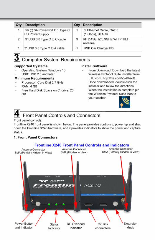
Table 1: X240 Front Panel Status Indicators
Antenna SMA Connectors: Antenna attaching points.
Excursion Mode: When configured Excursion mode, pressing this button will begin data capture - the same as the Record/Recording button on the X240 Window Datasource toolbar. The Excursion Mode button is inactive when X240 is connected to a computer. To operate in the Excursion mode, the X240 hardware must have been previously configured from the Wireless Protocol Suite prior to disconnecting from the computer. The X240 hardware will retain those configuration settings when disconnected from the computer. Refer to the Wireless Protocol Suite Hardware and Software User Manual for Excursion mode operating details.
Oculink Connectors: For connection to Frontline 8 channel PODs used for hardwired connection to user’s equipment under test.
Note: At this time the Oculink connectors are inactive.
Indicator Color State Status IndicatedPower None Off Unit is powered off
Purple Constant Insufficient Power
Green Constant Unit is switched on
Red Fast Flash Unit is approaching its maximum thermal load and should be shut down.
Constant Unit has reached thermal overload or Unit has started a
controlled/sequenced shutdown.
Status None Off Unit is powered off
Yellow Slow Flash Initializing (may not be seen if initialization is quick)
Fast Flash Unit is shutting down.
Constant Unit is in Recovery Mode.
Green Constant Unit is initialized and ready to capture.
Blue Slow Flash Unit is waiting for a Trigger (future).
Fast Flash Unit is capturing in Excursion mode or capture is not "OK" (future)
Constant Unit is capturing data
Red Constant The unit failed to initialize or has a System Error.
RF None Off Unit is powered off or Unit is not actively capturing data.
Green Constant Unit is capturing Bluetooth data.
Red Fast Flash The RF signal is too strong.
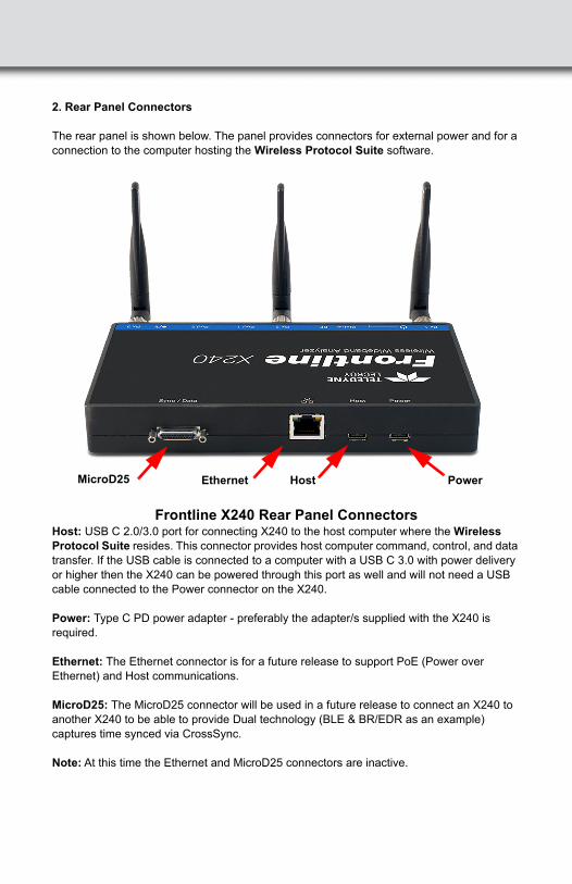
2. Rear Panel Connectors
The rear panel is shown below. The panel provides connectors for external power and for a connection to the computer hosting the Wireless Protocol Suite software.
Frontline X240 Rear Panel ConnectorsHost: USB C 2.0/3.0 port for connecting X240 to the host computer where the Wireless Protocol Suite resides. This connector provides host computer command, control, and data transfer. If the USB cable is connected to a computer with a USB C 3.0 with power delivery or higher then the X240 can be powered through this port as well and will not need a USB cable connected to the Power connector on the X240.
Power: Type C PD power adapter - preferably the adapter/s supplied with the X240 is required.
Ethernet: The Ethernet connector is for a future release to support PoE (Power over Ethernet) and Host communications.
MicroD25: The MicroD25 connector will be used in a future release to connect an X240 to another X240 to be able to provide Dual technology (BLE & BR/EDR as an example) captures time synced via CrossSync.
Note: At this time the Ethernet and MicroD25 connectors are inactive.
Host PowerMicroD25 Ethernet
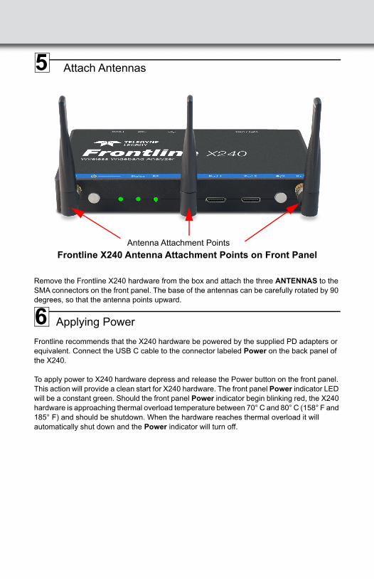
Attach Antennas
Frontline X240 Antenna Attachment Points on Front Panel
Remove the Frontline X240 hardware from the box and attach the three ANTENNAS to the SMA connectors on the front panel. The base of the antennas can be carefully rotated by 90 degrees, so that the antenna points upward.
Applying Power
Frontline recommends that the X240 hardware be powered by the supplied PD adapters or equivalent. Connect the USB C cable to the connector labeled Power on the back panel of the X240.
To apply power to X240 hardware depress and release the Power button on the front panel. This action will provide a clean start for X240 hardware. The front panel Power indicator LED will be a constant green. Should the front panel Power indicator begin blinking red, the X240
hardware is approaching thermal overload temperature between 70° C and 80° C (158° F and 185° F) and should be shutdown. When the hardware reaches thermal overload it will automatically shut down and the Power indicator will turn off.
Antenna Attachment Points
5
6
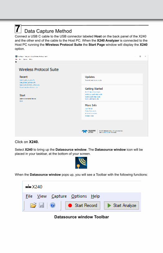
Data Capture MethodConnect a USB C cable to the USB connector labeled Host on the back panel of the X240 and the other end of the cable to the Host PC. When the X240 Analyzer is connected to the Host PC running the Wireless Protocol Suite the Start Page window will display the X240 option.
Click on X240.
Select X240 to bring up the Datasource window. The Datasource window icon will be placed in your taskbar, at the bottom of your screen.
When the Datasource window pops up, you will see a Toolbar with the following functions:
Datasource window Toolbar
7
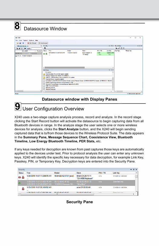
Datasource Window
Datasource window with Display Panes
User Configuration Overview
X240 uses a two-stage capture analysis process, record and analyze. In the record stage clicking the Start Record button will activate the datasource to begin capturing data from all Bluetooth devices in range. In the analyze stage the user selects one or more wireless devices for analysis, clicks the Start Analyze button, and the X240 will begin sending captured data that is to/from those devices to the Wireless Protocol Suite. The data appears in the Summary Pane, Message Sequence Chart, Coexistence View, Bluetooth Timeline, Low Energy Bluetooth Timeline, PER Stats, etc.
If any keys needed for decryption are known from past captures those keys are automatically applied to the devices under test. Prior to protocol analysis the user can enter any unknown keys. X240 will identify the specific key necessary for data decryption, for example Link Key, Passkey, PIN, or Temporary Key. Decryption keys are entered into the Security Pane.
Security Pane
8
9
Record: Begin Capture
When starting a capture session:• the active status of all devices is cleared in the Wireless Devices panes, • the Security pane is emptied, and• the Event Log pane retains all prior logged events.
On the Datasource Toolbar, click on the Start Record button or select Start Record from the Capture menu option. The Start Record button is also available in the Wireless Protocol Suite main window. In the Main window you can also select Start Recording from the Capture menu option. When the Start Record button changes to Stop Record the X240 hardware is capturing data from all active Bluetooth devices within range and recording data on the PC. Depending on license/capture configuration, only either Classic or LE will be displayed during any particular session.
On the Datasource Toolbar, clicking on the Stop Record button, or selecting Stop Recording from the Capture menu options will halt live capture. From the Main window you can click the Stop Record button or select Stop Recording from the Capture menu list to stop recording as well.
The Wireless Devices pane populates with any newly discovered devices. Selecting devices for analysis can be done while recording.
The Security pane will show all encrypted Bluetooth links.
The Event Log pane will begin to populate with information, warnings, and error messages.
The Status Bar will show a running total of captured packets.
Note: Starting a new capture session will clear all unsaved data from both the X240 hardware and the Wireless Protocol Suite. If it has not been saved, then a pop-up warning message will appear.
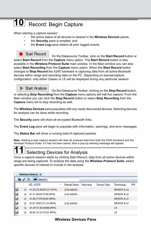
Selecting Devices for AnalysisOnce a capture session starts by clicking Start Record, data from all active devices within range are being captured. To analyze the data using the Wireless Protocol Suite, select specific devices of interest to include in the analysis.
Wireless Devices Pane
10
11
In the Wireless Devices pane, place a check in the row of each active device to be
analyzed. Active devices can also be selected while the recording is in progress.
Note: Data filtered by the device selection is an "OR" function, not an "AND" function. When selecting device1, device2, device3,… the recorded data filtered into the analyzer is data involving device1 OR device2 OR device3 OR …However, if the Options menu, analysis of LE Empty packets is selected an AND function is included. For example: (device2 AND LE Empty packets) OR (device3 AND LE Empty packets).
The following table lists some common data capture and device selection scenario.
Table 4 - Common Data Capture and Device Selection Scenarios
Once devices are selected, analysis of the capture can begin.
Start Analysis
The analysis begins by clicking on the Start Analyze button or selecting Start Analyze from the Capture menu. Alternatively click on the Start Analyze button in the Wireless Protocol Suite Main Window. In the Main window you can also select Start Analyzing from the Capture menu. The datasource will begin sending captured packets involving the selected device(s) to the Wireless Protocol Suite software.
Once analysis has begun, you cannot change the device selection. All device rows in the Wireless Devices pane are grayed-out. To stop the analysis, click the Stop Analyze button. You can then change your device selection and restart analysis by clicking the Start Analyze button.
To stop the analysis, click the button in the datasource or click
the button on the Wireless Protocol Suite Main window. You can also select Stop Analyze from the Capture menu in the datasource or the Stop Analyzing option in the Capture menu in the Main window as well.
Conducting analysis from a capture file is identical to the live capture method.
The Wireless Protocol Suite Main window is shown below:
ScenarioWireless Devices Pane
Selection
Analyzing traffic between a slave Device Under Test (DUT) and its master
Select only the slave DUT for analysis.
Analyzing all traffic involved in Inquires
In the Options menu select Analyze Inquiry Process Packets in the Options menu
12
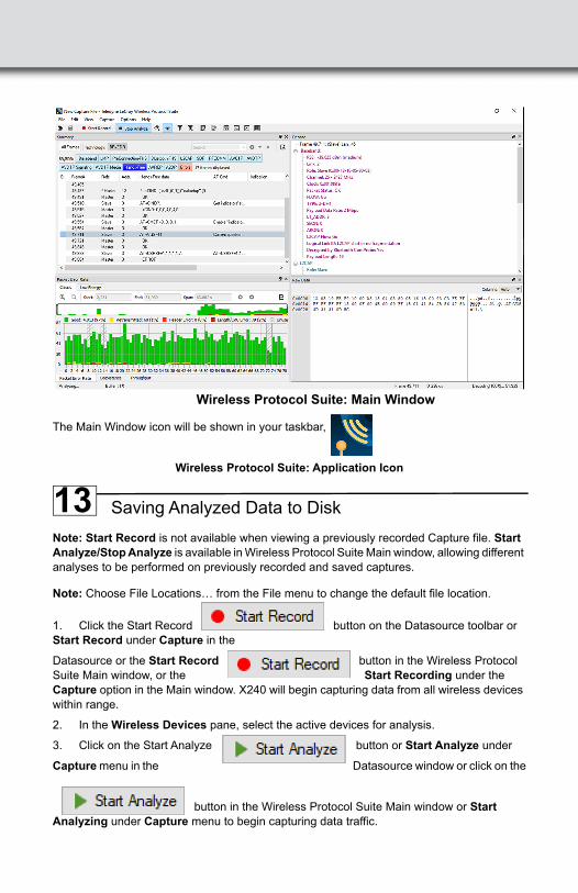
Wireless Protocol Suite: Main Window
The Main Window icon will be shown in your taskbar,
Wireless Protocol Suite: Application Icon
Saving Analyzed Data to Disk
Note: Start Record is not available when viewing a previously recorded Capture file. Start Analyze/Stop Analyze is available in Wireless Protocol Suite Main window, allowing different analyses to be performed on previously recorded and saved captures.
Note: Choose File Locations… from the File menu to change the default file location.
1. Click the Start Record button on the Datasource toolbar or Start Record under Capture in the
Datasource or the Start Record button in the Wireless Protocol Suite Main window, or the Start Recording under the Capture option in the Main window. X240 will begin capturing data from all wireless devices within range.
2. In the Wireless Devices pane, select the active devices for analysis.
3. Click on the Start Analyze button or Start Analyze under
Capture menu in the Datasource window or click on the
button in the Wireless Protocol Suite Main window or Start Analyzing under Capture menu to begin capturing data traffic.
13
Files are placed in My Capture Files folder by default and have a .cfa extension.
5. Watch the Status Bar on the Wireless Protocol Suite Main window to monitor how full the file is.
6. Click on the Stop Record button to stop recording.
7. Click the Stop Analyze button to stop analyzing.
8. Clicking on the Save icon will save the file to the selected location.
9. To clear captured data, click the Clear icon.
• If you select Clear after stopping analysis and have not saved it already, a dialog appears asking whether you want to save the data.
• You can click Save File and enter a file name when prompted.• If you choose Do Not Save, all data will be cleared.• If you choose Cancel, the dialog closes with no changes.
• If you select the Clear icon while a capture is occurring:
• The capture stops.• A dialog appears asking if you want to save the capture.• You can select Yes and save the capture or select No and close the
dialog. In either case, the existing capture file is cleared and a new capture file is started.
• If you choose Cancel, the dialog closes with no changes.
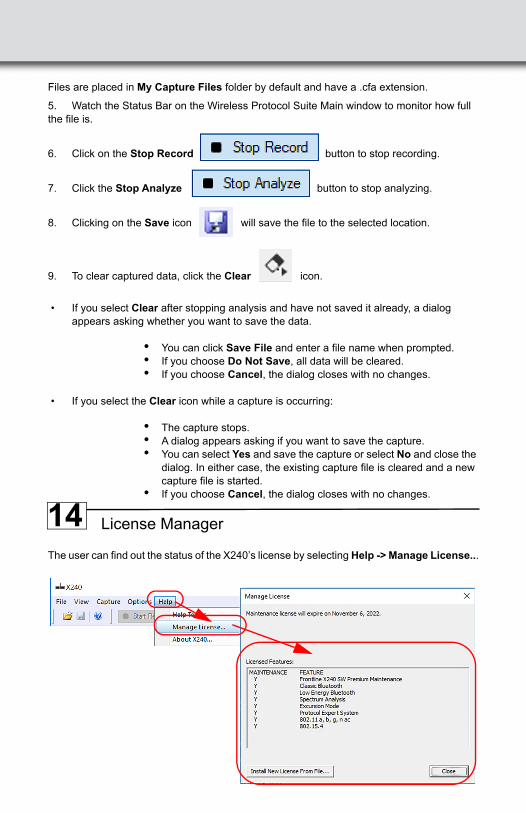
License Manager
The user can find out the status of the X240’s license by selecting Help -> Manage License...
14
Environmental Conditions
• Temperature: Operating 32° F to 104° F (0° C to 40° C) • Humidity: Operating 10% to 90% RH (non-condensing)
Other Specifications• Dimensions: 7.5” wide X 4" deep X 1" tall
190.5 mm X 101.6 mm X 25.4 mm
• Weight: 1.5 lbs
• Input Voltage: 5 V
• Max Power: 15 W
15
Trademarks and ServicemarksTeledyne LeCroy, Wireless Protocol Suite, Frontline and X240 Analyzer are trademarks of Teledyne LeCroy. Microsoft and Windows are registered trademarks of Microsoft Inc. The Bluetooth SIG owns the Bluetooth word mark and logos, and use of such marks is under license. All other trademarks are property of their respective companies.
ChangesProduct specifications are subject to change without notice.Teledyne LeCroy reserves the right to revise the information in this document without notice or penalty.
Teledyne LeCroy Customer SupportOnline Download
Periodically check the Teledyne LeCroy Protocol Solutions Group web site for software updates and other support related to this product. Software updates are available to users with a current Maintenance Agreement.
Web: http://www.fte.com/products/default.aspxE-mail: [email protected]: [email protected]
© 2019 Teledyne LeCroy, Inc. All rights reserved. Part Number: 931883-00 Rev A
This document may be printed and reproduced without additional permission, but all copies should contain this copyright notice.