Embed Size (px)
Citation preview
Part No.5347.Rev.11.05 Jan 2018 Printed in Canada
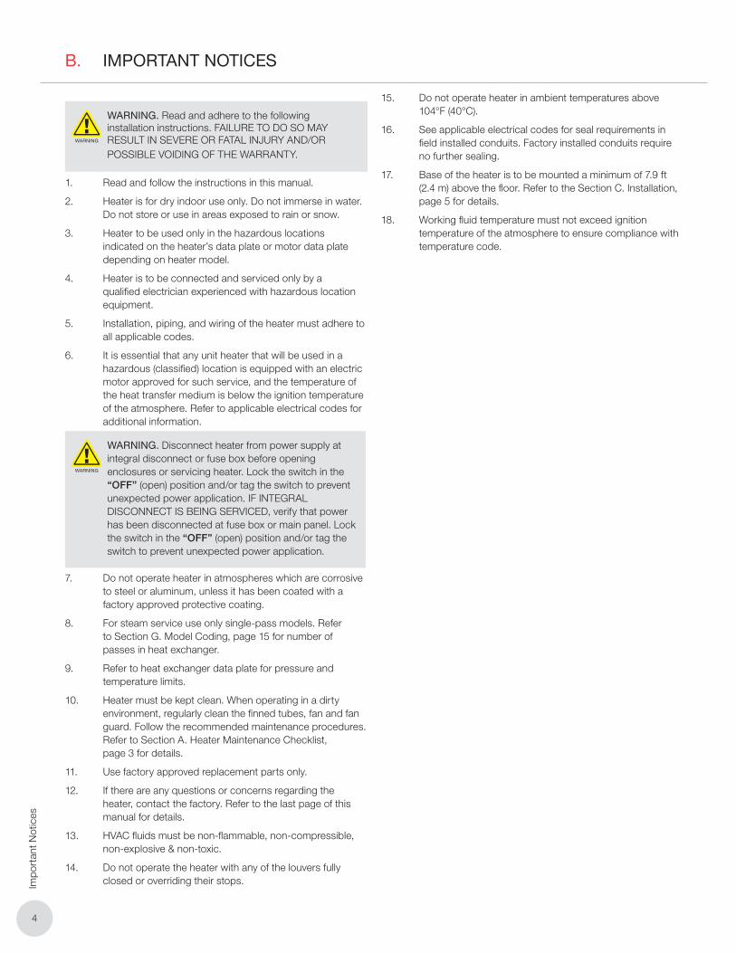
FR/HP SeriesFrost Resistant and High Pressure Heat-Exchanger Unit Heaters
Installation, Operation, & Maintenance Instructions
ISO 9001
®
Approved Locations
The Forced Air Heaters are CSA listed, certified for the following locations:
Class I, Division 1 & 2, Groups C & D; Class II, Division 1 & 2, Groups E, F, & G; Class III, Division 1 & 2; Temperature Code T3B 329˚F (165˚C) (Applicable Models Only)
For details of hazardous locations with potential for explosion, refer to the Canadian Electrical Code, Part 1, Section 18 or National Electrical Code articles 500-516.
TABLE OF CONTENTS
A. Heater Maintenance Checklist 3A.1 Periodic ................................................................................................................ 3
A.2 Annual .................................................................................................................. 3
B. Important Notices 4
C. Installation 5C.1 Description ........................................................................................................... 5
C.2 Location of Heaters .............................................................................................. 5
C.3 Noise Levels ......................................................................................................... 5
C.4 Mounting .............................................................................................................. 5
C.5 Clearances for Maintenance................................................................................. 6
C.6 Piping Applications ............................................................................................... 6
C.7 Wiring Schematics ............................................................................................... 7
D. Dimensions & Specifications 9
E. Repair & Replacement Procedures 10E.1 Cores .................................................................................................................. 10
E.2 Removal of Fan, Fan Guard, or Motor ................................................................. 10
E.3 FR/HP 36 Fan Guard .......................................................................................... 10
E.4 V-Belt Service: Removal, Installation, & Tensioning ............................................. 10
E.5 Fan Motor: Removal & Installation ....................................................................... 10
E.6 Drive Sheaves: Removal & Installation ................................................................ 10
E.7 Drive Frame: Removal ......................................................................................... 10
E.8 Fan Shaft Bearings: Removal & Installation ......................................................... 10
E.9 Fan: Removal & Installation ................................................................................. 11
F. Parts List 12F.1 FR/HP 12, 16, 20, 24, and 30 Models .................................................................. 12
F.2 XS40 Disconnect ................................................................................................ 13
F.3 FR/HP 36 Models ............................................................................................... 14
G. Model Coding 15
Ruffneck™ is a key brand of Thermon Heating Systems, Inc.
Copyright © 2018. All rights reserved.
33
Heater M
aintenance Checklist
A. HEATER MAINTENANCE CHECKLIST
WARNING
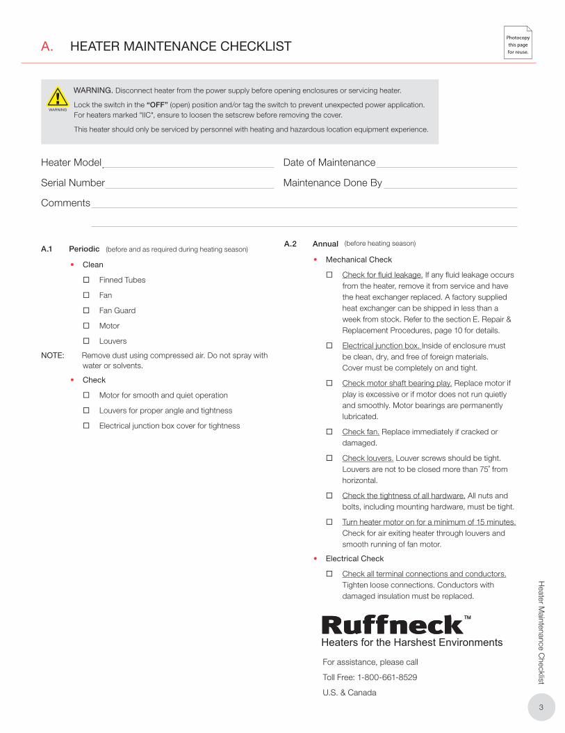
WARNING. Disconnect heater from the power supply before opening enclosures or servicing heater.
Lock the switch in the “OFF” (open) position and/or tag the switch to prevent unexpected power application. For heaters marked "IIC", ensure to loosen the setscrew before removing the cover.
This heater should only be serviced by personnel with heating and hazardous location equipment experience.
Heater Model
Serial Number
Comments
Date of Maintenance
Maintenance Done By
A.1 Periodic
• Clean
� Finned Tubes
� Fan
� Fan Guard
� Motor
� Louvers
NOTE: Remove dust using compressed air. Do not spray with water or solvents.
• Check
� Motor for smooth and quiet operation
� Louvers for proper angle and tightness
� Electrical junction box cover for tightness
A.2 Annual
• Mechanical Check
� Check for fluid leakage. If any fluid leakage occurs from the heater, remove it from service and have the heat exchanger replaced. A factory supplied heat exchanger can be shipped in less than a week from stock. Refer to the section E. Repair & Replacement Procedures, page 10 for details.
� Electrical junction box. Inside of enclosure must be clean, dry, and free of foreign materials. Cover must be completely on and tight.
� Check motor shaft bearing play. Replace motor if play is excessive or if motor does not run quietly and smoothly. Motor bearings are permanently lubricated.
� Check fan. Replace immediately if cracked or damaged.
� Check louvers. Louver screws should be tight. Louvers are not to be closed more than 75˚ from horizontal.
� Check the tightness of all hardware. All nuts and bolts, including mounting hardware, must be tight.
� Turn heater motor on for a minimum of 15 minutes. Check for air exiting heater through louvers and smooth running of fan motor.
• Electrical Check
� Check all terminal connections and conductors.Tighten loose connections. Conductors with damaged insulation must be replaced.
(before and as required during heating season)(before heating season)
Photocopy
this page
for reuse.
For assistance, please call
Toll Free: 1-800-661-8529
U.S. & Canada
44
Impo
rtan
t Not
ices
B. IMPORTANT NOTICES
WARNING
WARNING. Read and adhere to the following installation instructions. FAILURE TO DO SO MAY RESULT IN SEVERE OR FATAL INJURY AND/OR POSSIBLE VOIDING OF THE WARRANTY.
1. Read and follow the instructions in this manual.
2. Heater is for dry indoor use only. Do not immerse in water. Do not store or use in areas exposed to rain or snow.
3. Heater to be used only in the hazardous locations indicated on the heater’s data plate or motor data plate depending on heater model.
4. Heater is to be connected and serviced only by a qualified electrician experienced with hazardous location equipment.
5. Installation, piping, and wiring of the heater must adhere to all applicable codes.
6. It is essential that any unit heater that will be used in a hazardous (classified) location is equipped with an electric motor approved for such service, and the temperature of the heat transfer medium is below the ignition temperature of the atmosphere. Refer to applicable electrical codes for additional information.
WARNING
WARNING. Disconnect heater from power supply at integral disconnect or fuse box before opening enclosures or servicing heater. Lock the switch in the “OFF” (open) position and/or tag the switch to prevent unexpected power application. IF INTEGRAL DISCONNECT IS BEING SERVICED, verify that power has been disconnected at fuse box or main panel. Lock the switch in the “OFF” (open) position and/or tag the switch to prevent unexpected power application.
7. Do not operate heater in atmospheres which are corrosive to steel or aluminum, unless it has been coated with a factory approved protective coating.
8. For steam service use only single-pass models. Refer to Section G. Model Coding, page 15 for number of passes in heat exchanger.
9. Refer to heat exchanger data plate for pressure and temperature limits.
10. Heater must be kept clean. When operating in a dirty environment, regularly clean the finned tubes, fan and fan guard. Follow the recommended maintenance procedures. Refer to Section A. Heater Maintenance Checklist, page 3 for details.
11. Use factory approved replacement parts only.
12. If there are any questions or concerns regarding the heater, contact the factory. Refer to the last page of this manual for details.
13. HVAC fluids must be non-flammable, non-compressible, non-explosive & non-toxic.
14. Do not operate the heater with any of the louvers fully closed or overriding their stops.
15. Do not operate heater in ambient temperatures above 104°F (40°C).
16. See applicable electrical codes for seal requirements in field installed conduits. Factory installed conduits require no further sealing.
17. Base of the heater is to be mounted a minimum of 7.9 ft (2.4 m) above the floor. Refer to the Section C. Installation, page 5 for details.
18. Working fluid temperature must not exceed ignition temperature of the atmosphere to ensure compliance with temperature code.
55
Installation
C. INSTALLATION
C.1 Description
Two basic types of Ruffneck™ Heat Exchanger configurations are available from Thermon Heating Systems, Inc:
1. FR (Frost Resistant) Series - for steam service only, up to 100 psi (690 kPa) on select models
2. HP (High Pressure) Series - for steam and liquid service up to 400 psi (2,700 kPa) on select models
C.2 Location of Heaters
The following guidelines have been established by Thermon Heating Systems, Inc. to ensure that you properly locate the heaters in your building. These are only suggestions, and variations may be deemed necessary depending on application.
1. When occupant comfort is the major objective, heaters should be positioned so that the airflow is directed to areas of highest heat loss (i.e., doorways, windows and outside walls).
2. For personnel comfort, a less turbulent and more even air distribution is required. To achieve this effect a larger quantity of smaller unit heaters should be installed.
3. When equipment protection is of utmost concern, heaters should be positioned so that the airflow is directed towards the equipment.
4. In very large areas, arrangement of heaters should be such that the air will exit from one heater and be projected towards the inlet, or back, of another heater. A rotational airflow will result, with air circulation in the central area of the building.
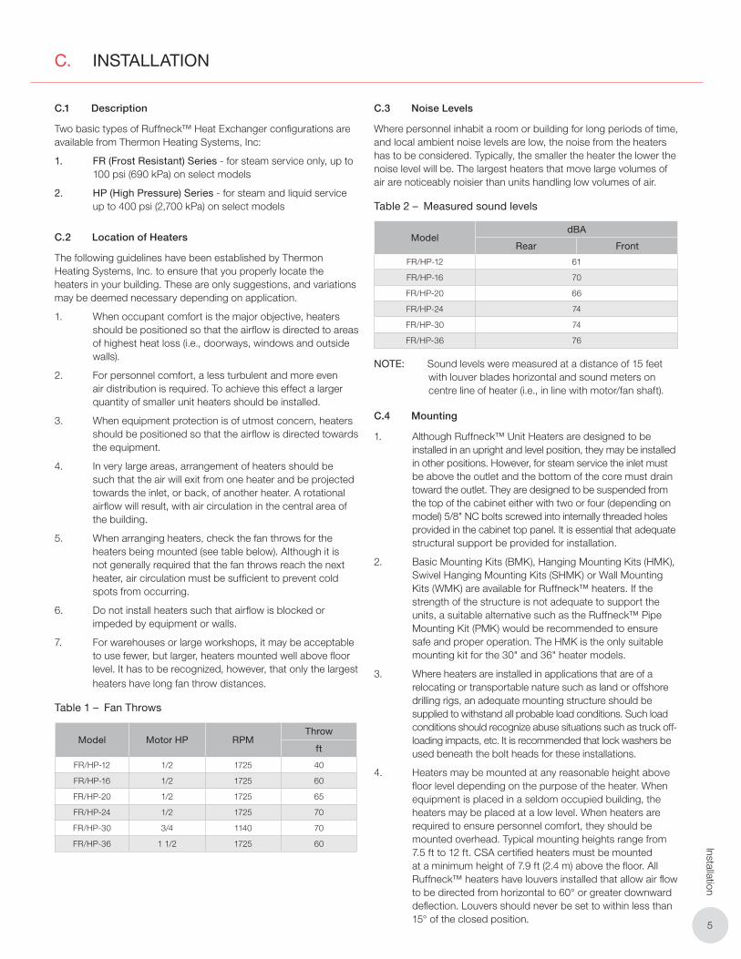
5. When arranging heaters, check the fan throws for the heaters being mounted (see table below). Although it is not generally required that the fan throws reach the next heater, air circulation must be sufficient to prevent cold spots from occurring.
6. Do not install heaters such that airflow is blocked or impeded by equipment or walls.
7. For warehouses or large workshops, it may be acceptable to use fewer, but larger, heaters mounted well above floor level. It has to be recognized, however, that only the largest heaters have long fan throw distances.
Table 1 – Fan Throws
Model Motor HP RPMThrow
ft
FR/HP-12 1/2 1725 40
FR/HP-16 1/2 1725 60
FR/HP-20 1/2 1725 65
FR/HP-24 1/2 1725 70
FR/HP-30 3/4 1140 70
FR/HP-36 1 1/2 1725 60
C.3 Noise Levels
Where personnel inhabit a room or building for long periods of time, and local ambient noise levels are low, the noise from the heaters has to be considered. Typically, the smaller the heater the lower the noise level will be. The largest heaters that move large volumes of air are noticeably noisier than units handling low volumes of air.
Table 2 – Measured sound levels
ModeldBA
Rear Front
FR/HP-12 61
FR/HP-16 70
FR/HP-20 66
FR/HP-24 74
FR/HP-30 74
FR/HP-36 76
NOTE: Sound levels were measured at a distance of 15 feet with louver blades horizontal and sound meters on centre line of heater (i.e., in line with motor/fan shaft).
C.4 Mounting
1. Although Ruffneck™ Unit Heaters are designed to be installed in an upright and level position, they may be installed in other positions. However, for steam service the inlet must be above the outlet and the bottom of the core must drain toward the outlet. They are designed to be suspended from the top of the cabinet either with two or four (depending on model) 5/8" NC bolts screwed into internally threaded holes provided in the cabinet top panel. It is essential that adequate structural support be provided for installation.
2. Basic Mounting Kits (BMK), Hanging Mounting Kits (HMK), Swivel Hanging Mounting Kits (SHMK) or Wall Mounting Kits (WMK) are available for Ruffneck™ heaters. If the strength of the structure is not adequate to support the units, a suitable alternative such as the Ruffneck™ Pipe Mounting Kit (PMK) would be recommended to ensure safe and proper operation. The HMK is the only suitable mounting kit for the 30" and 36" heater models.
3. Where heaters are installed in applications that are of a relocating or transportable nature such as land or offshore drilling rigs, an adequate mounting structure should be supplied to withstand all probable load conditions. Such load conditions should recognize abuse situations such as truck off-loading impacts, etc. It is recommended that lock washers be used beneath the bolt heads for these installations.
4. Heaters may be mounted at any reasonable height above floor level depending on the purpose of the heater. When equipment is placed in a seldom occupied building, the heaters may be placed at a low level. When heaters are required to ensure personnel comfort, they should be mounted overhead. Typical mounting heights range from 7.5 ft to 12 ft. CSA certified heaters must be mounted at a minimum height of 7.9 ft (2.4 m) above the floor. All Ruffneck™ heaters have louvers installed that allow air flow to be directed from horizontal to 60° or greater downward deflection. Louvers should never be set to within less than 15° of the closed position.
66
Inst
alla
tion
C.5 Clearances for Maintenance
It is important to provide adequate clearance around the heater for servicing. Allow enough space to permit easy fan or motor replacement. Do not position the back of the fan motor against a surface, as air for the cooling fan will be blocked. It is advisable to leave at least 2" of clearance between the rear of the motor and the nearest obstruction. For easy removal of the heat exchanger core assembly, it is important to leave clearance beneath the heater equal to the height of the heater cabinet plus an additional 2 inches.
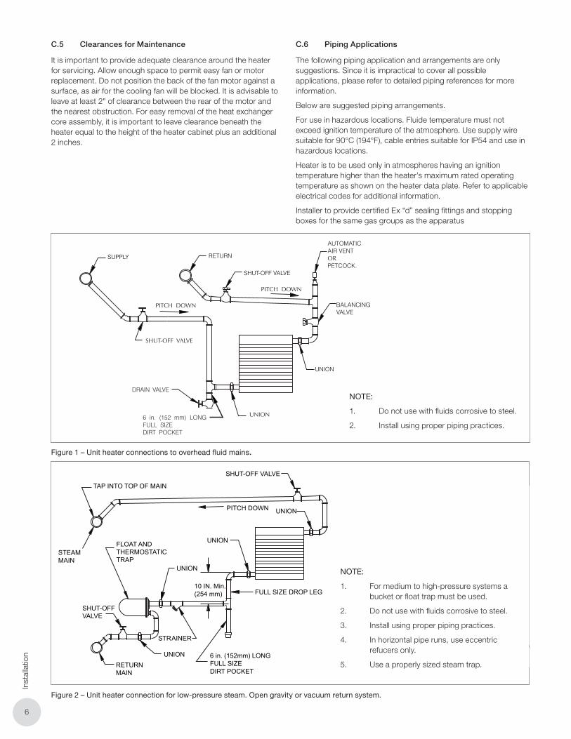
C.6 Piping Applications
The following piping application and arrangements are only suggestions. Since it is impractical to cover all possible applications, please refer to detailed piping references for more information.
Below are suggested piping arrangements.
For use in hazardous locations. Fluide temperature must not exceed ignition temperature of the atmosphere. Use supply wire suitable for 90°C (194°F), cable entries suitable for IP54 and use in hazardous locations.
Heater is to be used only in atmospheres having an ignition temperature higher than the heater’s maximum rated operating temperature as shown on the heater data plate. Refer to applicable electrical codes for additional information.
Installer to provide certified Ex “d” sealing fittings and stopping boxes for the same gas groups as the apparatus
SHUT-OFF VALVE
PITCH DOWN
UNION
6 in. (152 mm) LONGFULL SIZE DIRT POCKET
RETURNSUPPLY
PITCH DOWN
DRAIN VALVE
AUTOMATICAIR VENTORPETCOCK.
SHUT-OFF VALVE
BALANCING VALVE
UNION
Where heaters are installed in applications that are of a relocatable or transportable nature such as land or offshore drilling rigs, an adequate mounting structure should be supplied to withstand all probable load conditions. Such load conditions should recognize abuse situations such as truck off-loading impacts, etc. It is recommended that lock washers be used beneath the bolt heads for these installations.
Heaters may be mounted at any reasonable height above floor level depending on the purpose of the heater. When equipment is placed in a seldomly occupied building, the heaters may be placed at a low level. When heaters are required to ensure personnel comfort, they should be mounted overhead. Typically, mounting heights range from 7 1/2 feet to 12 feet. All Ruffneck™ heaters have louvers installed that allow air flow to be directed from horizontal to 60 degrees or greater downward deflection. Louvers should never be set to within less than 15 degrees of the closed position.
CLEARANCES FOR MAINTENANCE It is important to provide adequate clearance around the heater for servicing. Allow enough space to permit easy fan or motor replacement. Do not position the back of the fan motor against a surface, as air for the cooling fan will be blocked. It is advisable to leave at least 2” clearance between the rear of the motor and the nearest obstruction. For easy removal of the heat exchanger core assembly, it is important to leave clearance beneath the heater equal to the height of the heater cabinet plus two inches.
PIPING APPLICATIONS
The following piping application and arrangements are only suggestions. Since it is impractical to cover all possible applications, please refer to detailed piping references for more information.
Below are suggested piping arrangements.
NOTES:1. Do not use with fluids corrosive to steel2. Install using proper piping practices.
NOTE:
1. Do not use with fluids corrosive to steel.
2. Install using proper piping practices.
Figure 1 – Unit heater connections to overhead fluid mains.
FIG.2UNIT HEATER CONNECTION
FOR LOW-PRESSURE STEAM,OPEN GRAVITY OR VACUUM
RETURN SYSTEM
NOTES:
1. For medium to high-pressure systems a bucket
or float trap must be used.
2. Do not use with fluids corrosive to steel.
3. Install using proper piping practices
4. In horizontal pipe runs, use eccentric reducers only.
5. Use a properly sized steam trap.
TAP INTO TOP OF MAIN
SHUT-OFF VALVE
UNIONPITCH DOWN
UNION
RETURNMAIN
SHUT-OFFVALVE
FLOAT AND THERMOSTATIC TRAP
STEAM MAIN
UNION
10 IN. Min.(254 mm) FULL SIZE DROP LEG
6 in. (152mm) LONGFULL SIZEDIRT POCKET
UNION
NOTE:
1. For medium to high-pressure systems a bucket or float trap must be used.
2. Do not use with fluids corrosive to steel.
3. Install using proper piping practices.
4. In horizontal pipe runs, use eccentric refucers only.
5. Use a properly sized steam trap.
Figure 2 – Unit heater connection for low-pressure steam. Open gravity or vacuum return system.
77
Installation
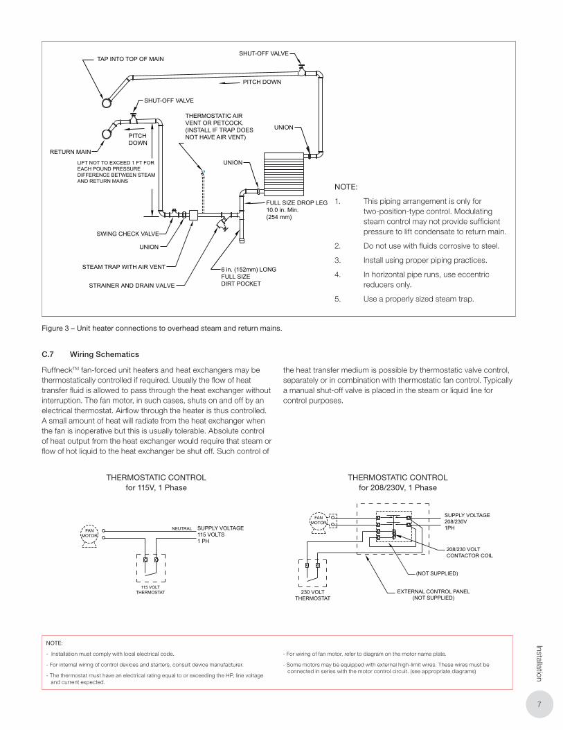
NOTES:1. This piping arrangement is only for two-position-type
control. Modulating steam control may not provide
sufficient pressure to lift condensate to return main.
2. Do not use with fluids corrosive to steel.
3. Install using proper piping practices.
4. In horizontal pipe runs use eccentric reducers only.
5. Use a properly sized steam trap.
TAP INTO TOP OF MAIN
SHUT-OFF VALVE
UNIONPITCH DOWN
UNION
RETURNMAIN
TAP INTO TOP OF MAINSHUT-OFF VALVE
PITCH DOWN
FULL SIZE DROP LEG10.0 in. Min.(254 mm)
SHUT-OFF VALVE
RETURN MAIN
PITCH DOWN
LIFT NOT TO EXCEED 1 FT FOR EACH POUND PRESSURE DIFFERENCE BETWEEN STEAMAND RETURN MAINS
THERMOSTATIC AIRVENT OR PETCOCK.(INSTALL IF TRAP DOESNOT HAVE AIR VENT)
SHUT-OFFVALVE
FLOAT AND THERMOSTATIC TRAP
STEAM MAIN
UNION
UNION
UNION
UNION
SWING CHECK VALVE
STEAM TRAP WITH AIR VENT
STRAINER AND DRAIN VALVE
6 in. (152mm) LONGFULL SIZEDIRT POCKET
STRAINER
10 IN. Min.(254 mm) FULL SIZE DROP LEG
6 in. (152mm) LONGFULL SIZEDIRT POCKET
UNION
NOTES:1. For medium to high-pressure systems a bucket
or float trap must be used.
2. Do not use with fluids corrosive to steel.
3. Install using proper piping practices
4. In horizontal pipe runs, use eccentric reducers only.
5. Use a properly sized steam trap.
NOTE:
1. This piping arrangement is only for two-position-type control. Modulating steam control may not provide sufficient pressure to lift condensate to return main.
2. Do not use with fluids corrosive to steel.
3. Install using proper piping practices.
4. In horizontal pipe runs, use eccentric reducers only.
5. Use a properly sized steam trap.
Figure 3 – Unit heater connections to overhead steam and return mains.
C.7 Wiring Schematics
RuffneckTM fan-forced unit heaters and heat exchangers may be thermostatically controlled if required. Usually the flow of heat transfer fluid is allowed to pass through the heat exchanger without interruption. The fan motor, in such cases, shuts on and off by an electrical thermostat. Airflow through the heater is thus controlled. A small amount of heat will radiate from the heat exchanger when the fan is inoperative but this is usually tolerable. Absolute control of heat output from the heat exchanger would require that steam or flow of hot liquid to the heat exchanger be shut off. Such control of
the heat transfer medium is possible by thermostatic valve control, separately or in combination with thermostatic fan control. Typically a manual shut-off valve is placed in the steam or liquid line for control purposes.
ELECTRICAL WIRING
7
RuffneckTM fan-forced unit heaters and heat exchangers may be thermostatically controlled if required. Usually the flow of heat transfer fluid is allowed to pass through the heat exchanger without interruption. The fan motor, in such cases, shuts on and off by an electrical thermostat. Air flow through the heater is thus controlled. A small amount of heat will radiate from the heat exchanger when the fan is inoperative but this is usually tolerable. Absolute control of heat output from the heat exchanger would require that steam or flow of hot liquid to the heat exchanger be shut off. Such control of the heat transfer medium is possible by thermostatic valve control, separately or in combination with thermostatic fan control. Typically a manual shut-off valve is placed in the steam or liquid line for control purposes.
SUPPLY VOLTAGE208/230V1PH
208/230 VOLTCONTACTOR COIL
(NOT SUPPLIED)
EXTERNAL CONTROL PANEL(NOT SUPPLIED)
230 VOLTTHERMOSTAT
THERMOSTATIC CONTROL FOR208/230 VOLTS, 1 PHASE
THERMOSTATIC CONTROL FOR115 VOLTS, 1 PHASE
THERMOSTATIC CONTROL FOR 208/230 VOLT, 3 PHASE MOTORSC/W EXTERNAL HIGH-LIMIT WIRES
THERMOSTATIC CONTROL FOR208/230 VOLTS, 3 PHASE
THERMOSTATIC CONTROL FOR460/600 VOLTS, 3 PHASE
THERMOSTATIC CONTROL FOR 460/600 VOLT, 3 PHASE MOTORSC/W EXTERNAL HIGH-LIMIT WIRES
FANMOTOR
FANMOTOR
FANMOTOR
FANMOTOR
SUPPLY VOLTAGE115 VOLTS1 PH
NEUTRAL
115 VOLTTHERMOSTAT
SUPPLYVOLTAGE
208/230VOLTS3PH
SUPPLY VOLTAGE208/230 VOLTS 3PH
208/230 VOLTCONTACTOR COIL
3 POLE CONTACTOR RELAY(NOT SUPPLIED)
EXTERNAL CONTROL PANEL(NOT SUPPLIED)
3 POLE CONTACTOR RELAY(NOT SUPPLIED)
SUPPLY VOLTAGE460/6003PH
VOLTAGETRANSFORMER(NOT SUPPLIED)
EXTERNAL CONTROL PANEL(NOT SUPPLIED)
24 TO 230 VOLTTHERMOSTAT
230 VOLTTHERMOSTAT
208/230 VOLTCONTACTOR COIL
MOTOR C/W EXTERNALHIGH-LIMIT WIRES
230 VOLTTHERMOSTAT
EXTERNAL CONTROL PANEL(NOT SUPPLIED)
SUPPLY VOLTAGE460/600VOLTS3PH
EXTERNAL CONTROL PANEL(NOT SUPPLIED)
VOLTAGETRANSFORMER(NOT SUPPLIED)
24 TO 230 VOLTTHERMOSTAT
3 POLE CONTACTOR RELAY(NOT SUPPLIED)MOTOR C/W EXTERNAL
HIGH-LIMIT WIRES
3 POLE CONTACTOR RELAY(NOT SUPPLIED)
FANMOTOR
FANMOTOR
24 TO 230VOLTS
24 TO 230VOLTS
NOTES:- Installation must comply with local electrical code.- For internal wiring of control devices and starters, consult device manufacturer.- The thermostat must have an electrical rating equal to or exceeding the HP, line voltage and current expected.- For wiring of fan motor, refer to diagram on the motor name plate.- Some motors may be equipped with external high-limit wires. These wires must be connected in series with the motor control circuit. (see appropriate diagrams above)
THERMOSTATIC CONTROLfor 208/230V, 1 Phase
THERMOSTATIC CONTROLfor 115V, 1 Phase
NOTE:
- Installation must comply with local electrical code.
- For internal wiring of control devices and starters, consult device manufacturer.
- The thermostat must have an electrical rating equal to or exceeding the HP, line voltage and current expected.
- For wiring of fan motor, refer to diagram on the motor name plate.
- Some motors may be equipped with external high-limit wires. These wires must be connected in series with the motor control circuit. (see appropriate diagrams)
88
Inst
alla
tion
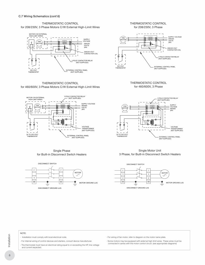
C.7 Wiring Schematics (cont’d)
ELECTRICAL WIRING
7
RuffneckTM fan-forced unit heaters and heat exchangers may be thermostatically controlled if required. Usually the flow of heat transfer fluid is allowed to pass through the heat exchanger without interruption. The fan motor, in such cases, shuts on and off by an electrical thermostat. Air flow through the heater is thus controlled. A small amount of heat will radiate from the heat exchanger when the fan is inoperative but this is usually tolerable. Absolute control of heat output from the heat exchanger would require that steam or flow of hot liquid to the heat exchanger be shut off. Such control of the heat transfer medium is possible by thermostatic valve control, separately or in combination with thermostatic fan control. Typically a manual shut-off valve is placed in the steam or liquid line for control purposes.
SUPPLY VOLTAGE208/230V1PH
208/230 VOLTCONTACTOR COIL
(NOT SUPPLIED)
EXTERNAL CONTROL PANEL(NOT SUPPLIED)
230 VOLTTHERMOSTAT
THERMOSTATIC CONTROL FOR208/230 VOLTS, 1 PHASE
THERMOSTATIC CONTROL FOR115 VOLTS, 1 PHASE
THERMOSTATIC CONTROL FOR 208/230 VOLT, 3 PHASE MOTORSC/W EXTERNAL HIGH-LIMIT WIRES
THERMOSTATIC CONTROL FOR208/230 VOLTS, 3 PHASE
THERMOSTATIC CONTROL FOR460/600 VOLTS, 3 PHASE
THERMOSTATIC CONTROL FOR 460/600 VOLT, 3 PHASE MOTORSC/W EXTERNAL HIGH-LIMIT WIRES
FANMOTOR
FANMOTOR
FANMOTOR
FANMOTOR
SUPPLY VOLTAGE115 VOLTS1 PH
NEUTRAL
115 VOLTTHERMOSTAT
SUPPLYVOLTAGE
208/230VOLTS3PH
SUPPLY VOLTAGE208/230 VOLTS 3PH
208/230 VOLTCONTACTOR COIL
3 POLE CONTACTOR RELAY(NOT SUPPLIED)
EXTERNAL CONTROL PANEL(NOT SUPPLIED)
3 POLE CONTACTOR RELAY(NOT SUPPLIED)
SUPPLY VOLTAGE460/6003PH
VOLTAGETRANSFORMER(NOT SUPPLIED)
EXTERNAL CONTROL PANEL(NOT SUPPLIED)
24 TO 230 VOLTTHERMOSTAT
230 VOLTTHERMOSTAT
208/230 VOLTCONTACTOR COIL
MOTOR C/W EXTERNALHIGH-LIMIT WIRES
230 VOLTTHERMOSTAT
EXTERNAL CONTROL PANEL(NOT SUPPLIED)
SUPPLY VOLTAGE460/600VOLTS3PH
EXTERNAL CONTROL PANEL(NOT SUPPLIED)
VOLTAGETRANSFORMER(NOT SUPPLIED)
24 TO 230 VOLTTHERMOSTAT
3 POLE CONTACTOR RELAY(NOT SUPPLIED)MOTOR C/W EXTERNAL
HIGH-LIMIT WIRES
3 POLE CONTACTOR RELAY(NOT SUPPLIED)
FANMOTOR
FANMOTOR
24 TO 230VOLTS
24 TO 230VOLTS
NOTES:- Installation must comply with local electrical code.- For internal wiring of control devices and starters, consult device manufacturer.- The thermostat must have an electrical rating equal to or exceeding the HP, line voltage and current expected.- For wiring of fan motor, refer to diagram on the motor name plate.- Some motors may be equipped with external high-limit wires. These wires must be connected in series with the motor control circuit. (see appropriate diagrams above)
THERMOSTATIC CONTROLfor 208/230V, 3 Phase
THERMOSTATIC CONTROLfor 208/230V, 3 Phase Motors C/W External High-Limit Wires
ELECTRICAL WIRING
7
RuffneckTM fan-forced unit heaters and heat exchangers may be thermostatically controlled if required. Usually the flow of heat transfer fluid is allowed to pass through the heat exchanger without interruption. The fan motor, in such cases, shuts on and off by an electrical thermostat. Air flow through the heater is thus controlled. A small amount of heat will radiate from the heat exchanger when the fan is inoperative but this is usually tolerable. Absolute control of heat output from the heat exchanger would require that steam or flow of hot liquid to the heat exchanger be shut off. Such control of the heat transfer medium is possible by thermostatic valve control, separately or in combination with thermostatic fan control. Typically a manual shut-off valve is placed in the steam or liquid line for control purposes.
SUPPLY VOLTAGE208/230V1PH
208/230 VOLTCONTACTOR COIL
(NOT SUPPLIED)
EXTERNAL CONTROL PANEL(NOT SUPPLIED)
230 VOLTTHERMOSTAT
THERMOSTATIC CONTROL FOR208/230 VOLTS, 1 PHASE
THERMOSTATIC CONTROL FOR115 VOLTS, 1 PHASE
THERMOSTATIC CONTROL FOR 208/230 VOLT, 3 PHASE MOTORSC/W EXTERNAL HIGH-LIMIT WIRES
THERMOSTATIC CONTROL FOR208/230 VOLTS, 3 PHASE
THERMOSTATIC CONTROL FOR460/600 VOLTS, 3 PHASE
THERMOSTATIC CONTROL FOR 460/600 VOLT, 3 PHASE MOTORSC/W EXTERNAL HIGH-LIMIT WIRES
FANMOTOR
FANMOTOR
FANMOTOR
FANMOTOR
SUPPLY VOLTAGE115 VOLTS1 PH
NEUTRAL
115 VOLTTHERMOSTAT
SUPPLYVOLTAGE
208/230VOLTS3PH
SUPPLY VOLTAGE208/230 VOLTS 3PH
208/230 VOLTCONTACTOR COIL
3 POLE CONTACTOR RELAY(NOT SUPPLIED)
EXTERNAL CONTROL PANEL(NOT SUPPLIED)
3 POLE CONTACTOR RELAY(NOT SUPPLIED)
SUPPLY VOLTAGE460/6003PH
VOLTAGETRANSFORMER(NOT SUPPLIED)
EXTERNAL CONTROL PANEL(NOT SUPPLIED)
24 TO 230 VOLTTHERMOSTAT
230 VOLTTHERMOSTAT
208/230 VOLTCONTACTOR COIL
MOTOR C/W EXTERNALHIGH-LIMIT WIRES
230 VOLTTHERMOSTAT
EXTERNAL CONTROL PANEL(NOT SUPPLIED)
SUPPLY VOLTAGE460/600VOLTS3PH
EXTERNAL CONTROL PANEL(NOT SUPPLIED)
VOLTAGETRANSFORMER(NOT SUPPLIED)
24 TO 230 VOLTTHERMOSTAT
3 POLE CONTACTOR RELAY(NOT SUPPLIED)MOTOR C/W EXTERNAL
HIGH-LIMIT WIRES
3 POLE CONTACTOR RELAY(NOT SUPPLIED)
FANMOTOR
FANMOTOR
24 TO 230VOLTS
24 TO 230VOLTS
NOTES:- Installation must comply with local electrical code.- For internal wiring of control devices and starters, consult device manufacturer.- The thermostat must have an electrical rating equal to or exceeding the HP, line voltage and current expected.- For wiring of fan motor, refer to diagram on the motor name plate.- Some motors may be equipped with external high-limit wires. These wires must be connected in series with the motor control circuit. (see appropriate diagrams above)
THERMOSTATIC CONTROLfor 460/600V, 3 Phase Motors C/W External High-Limit Wires
ELECTRICAL WIRING
7
RuffneckTM fan-forced unit heaters and heat exchangers may be thermostatically controlled if required. Usually the flow of heat transfer fluid is allowed to pass through the heat exchanger without interruption. The fan motor, in such cases, shuts on and off by an electrical thermostat. Air flow through the heater is thus controlled. A small amount of heat will radiate from the heat exchanger when the fan is inoperative but this is usually tolerable. Absolute control of heat output from the heat exchanger would require that steam or flow of hot liquid to the heat exchanger be shut off. Such control of the heat transfer medium is possible by thermostatic valve control, separately or in combination with thermostatic fan control. Typically a manual shut-off valve is placed in the steam or liquid line for control purposes.
SUPPLY VOLTAGE208/230V1PH
208/230 VOLTCONTACTOR COIL
(NOT SUPPLIED)
EXTERNAL CONTROL PANEL(NOT SUPPLIED)
230 VOLTTHERMOSTAT
THERMOSTATIC CONTROL FOR208/230 VOLTS, 1 PHASE
THERMOSTATIC CONTROL FOR115 VOLTS, 1 PHASE
THERMOSTATIC CONTROL FOR 208/230 VOLT, 3 PHASE MOTORSC/W EXTERNAL HIGH-LIMIT WIRES
THERMOSTATIC CONTROL FOR208/230 VOLTS, 3 PHASE
THERMOSTATIC CONTROL FOR460/600 VOLTS, 3 PHASE
THERMOSTATIC CONTROL FOR 460/600 VOLT, 3 PHASE MOTORSC/W EXTERNAL HIGH-LIMIT WIRES
FANMOTOR
FANMOTOR
FANMOTOR
FANMOTOR
SUPPLY VOLTAGE115 VOLTS1 PH
NEUTRAL
115 VOLTTHERMOSTAT
SUPPLYVOLTAGE
208/230VOLTS3PH
SUPPLY VOLTAGE208/230 VOLTS 3PH
208/230 VOLTCONTACTOR COIL
3 POLE CONTACTOR RELAY(NOT SUPPLIED)
EXTERNAL CONTROL PANEL(NOT SUPPLIED)
3 POLE CONTACTOR RELAY(NOT SUPPLIED)
SUPPLY VOLTAGE460/6003PH
VOLTAGETRANSFORMER(NOT SUPPLIED)
EXTERNAL CONTROL PANEL(NOT SUPPLIED)
24 TO 230 VOLTTHERMOSTAT
230 VOLTTHERMOSTAT
208/230 VOLTCONTACTOR COIL
MOTOR C/W EXTERNALHIGH-LIMIT WIRES
230 VOLTTHERMOSTAT
EXTERNAL CONTROL PANEL(NOT SUPPLIED)
SUPPLY VOLTAGE460/600VOLTS3PH
EXTERNAL CONTROL PANEL(NOT SUPPLIED)
VOLTAGETRANSFORMER(NOT SUPPLIED)
24 TO 230 VOLTTHERMOSTAT
3 POLE CONTACTOR RELAY(NOT SUPPLIED)MOTOR C/W EXTERNAL
HIGH-LIMIT WIRES
3 POLE CONTACTOR RELAY(NOT SUPPLIED)
FANMOTOR
FANMOTOR
24 TO 230VOLTS
24 TO 230VOLTS
NOTES:- Installation must comply with local electrical code.- For internal wiring of control devices and starters, consult device manufacturer.- The thermostat must have an electrical rating equal to or exceeding the HP, line voltage and current expected.- For wiring of fan motor, refer to diagram on the motor name plate.- Some motors may be equipped with external high-limit wires. These wires must be connected in series with the motor control circuit. (see appropriate diagrams above)
THERMOSTATIC CONTROLfor 460/600V, 3 Phase
Single Phasefor Built-in Disconnect Switch Heaters
Single Motor Unit3 Phase, for Built-in Disconnect Switch Heaters
NOTE:
- Installation must comply with local electrical code.
- For internal wiring of control devices and starters, consult device manufacturer.
- The thermostat must have an electrical rating equal to or exceeding the HP, line voltage and current expected.
- For wiring of fan motor, refer to diagram on the motor name plate.
- Some motors may be equipped with external high-limit wires. These wires must be connected in series with the motor control circuit. (see appropriate diagrams)

99
Dim
ensions & S
pecifications \ Dim
ensions & S
pecifications
D. DIMENSIONS & SPECIFICATIONS
Table 3 – Physical Dimensions for A to F
A B C D E F
in mm in mm in mm in mm in mm in mm
FR/HP 12 16 5/6 415 16 3/8 416 4 102 9 3/4 248 12 5/8 320 11 280
FR/HP 16 20 5/16 516 20 5/6 517 4 102 9 3/4 248 15 1/2 394 15 381
FR/HP 20 24 5/6 618 24 5/16 618 4 102 10 1/2 267 19 1/2 495 17 432
FR/HP 24 28 3/8 720 28 1/4 718 4 5/8 118 11 13/16 300 23 7/16 596 19 11/16 500
FR/HP 30 34 7/16 874 34 5/16 872 5 11/16 145 13 3/4 350 29 1/2 750 25 9/16 650
FR/HP 36 42 5/8 1083 42 5/8 1083 5 1/2 140 23 5/8 600 37 3/8 950 29 1/2 750
Table 4 – Physical Dimensions for G to M
G H I J K* (max.) L* (max.) M
in mm in mm in mm in mm in mm in mm in mm
FR/HP 12 N/A N/A 6 3/4 172 2 5/8 68 1 7/8 48 21 1/4 540 1 5/8 42 24 3/8 619
FR/HP 16 1 3/4 44 5 3/4 147 2 5/8 68 2 3/4 70 21 1/4 540 1 5/8 42 28 5/16 720
FR/HP 20 2 1/2 63 5 3/4 146 3 5/8 93 2 7/8 73 22 7/16 570 1 5/8 42 32 5/16 821
FR/HP 24 2 3/4 70 6 11/16 170 4 5/16 109 3 76 23 5/8 600 1 5/8 42 36 1/4 921
FR/HP 30 3 1/8 80 7 1/2 190 4 3/8 111 3 1/8 80 25 3/16 640 1 7/8 47 42 5/16 1075
FR/HP 36 3 1/8 80 9 7/16 240 6 7/16 163 3 76 34 5/8 880 1 3/4 45 50 5/8 1286
Table 5 – Weights
12 in 16 in 20 in 24 in 30 in 36 in
Core
Weight
lbs 27 38 48 91 121 175
kg 12 17 22 41 55 79
Unit Weight lbs 80 100 126 191 286 444
kg 36 45 57 87 130 202
Shipping
Weight
lbs 132 148 174 214 321 526
kg 60 67 79 97 146 239
***
Figure 4 – Physical dimensions
NOTE:
* May vary with motor used.
** FR/HP 12 has only two mounting holes on
top of the unit.
***2" NPT male and 2" 300# Flange not
available on FR/HP36 units.
1010
Rep
air
& R
epla
cem
ent P
roce
dure
s
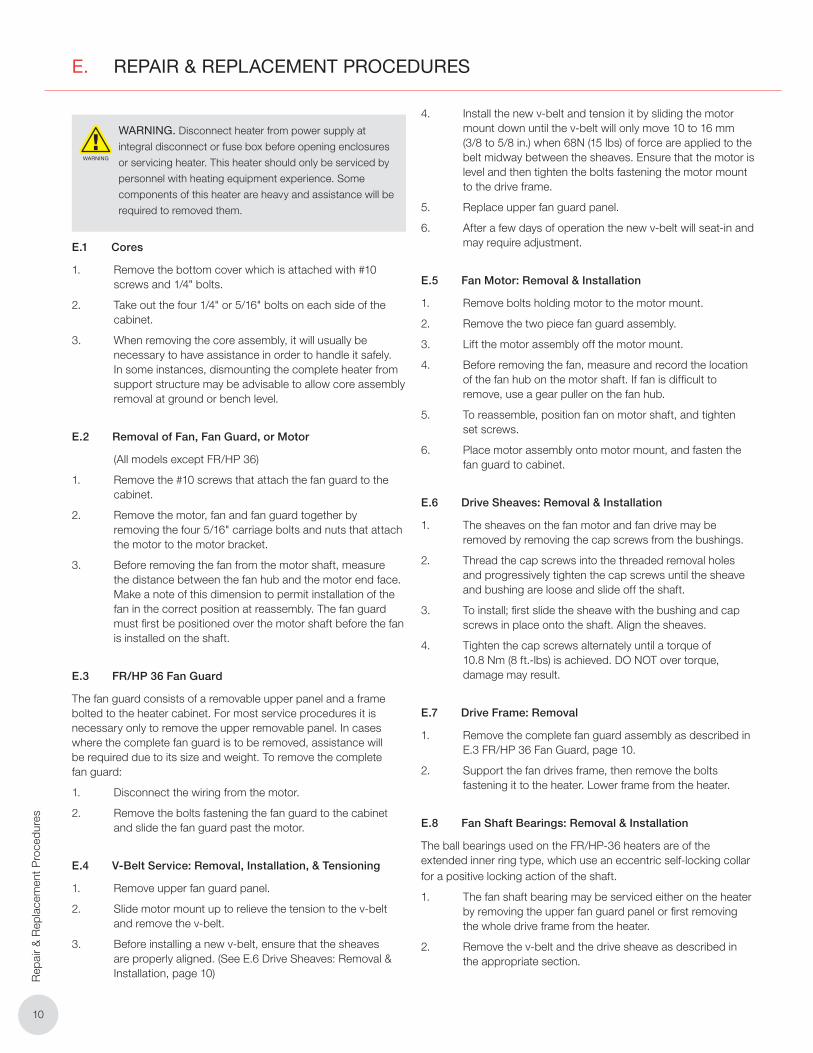
E. REPAIR & REPLACEMENT PROCEDURES
WARNING
WARNING. Disconnect heater from power supply at
integral disconnect or fuse box before opening enclosures
or servicing heater. This heater should only be serviced by
personnel with heating equipment experience. Some
components of this heater are heavy and assistance will be
required to removed them.
E.1 Cores
1. Remove the bottom cover which is attached with #10 screws and 1/4" bolts.
2. Take out the four 1/4" or 5/16" bolts on each side of the cabinet.
3. When removing the core assembly, it will usually be necessary to have assistance in order to handle it safely. In some instances, dismounting the complete heater from support structure may be advisable to allow core assembly removal at ground or bench level.
E.2 Removal of Fan, Fan Guard, or Motor
(All models except FR/HP 36)
1. Remove the #10 screws that attach the fan guard to the cabinet.
2. Remove the motor, fan and fan guard together by removing the four 5/16" carriage bolts and nuts that attach the motor to the motor bracket.
3. Before removing the fan from the motor shaft, measure the distance between the fan hub and the motor end face. Make a note of this dimension to permit installation of the fan in the correct position at reassembly. The fan guard must first be positioned over the motor shaft before the fan is installed on the shaft.
E.3 FR/HP 36 Fan Guard
The fan guard consists of a removable upper panel and a frame bolted to the heater cabinet. For most service procedures it is necessary only to remove the upper removable panel. In cases where the complete fan guard is to be removed, assistance will be required due to its size and weight. To remove the complete fan guard:
1. Disconnect the wiring from the motor.
2. Remove the bolts fastening the fan guard to the cabinet and slide the fan guard past the motor.
E.4 V-Belt Service: Removal, Installation, & Tensioning
1. Remove upper fan guard panel.
2. Slide motor mount up to relieve the tension to the v-belt and remove the v-belt.
3. Before installing a new v-belt, ensure that the sheaves are properly aligned. (See E.6 Drive Sheaves: Removal & Installation, page 10)
4. Install the new v-belt and tension it by sliding the motor mount down until the v-belt will only move 10 to 16 mm (3/8 to 5/8 in.) when 68N (15 lbs) of force are applied to the belt midway between the sheaves. Ensure that the motor is level and then tighten the bolts fastening the motor mount to the drive frame.
5. Replace upper fan guard panel.
6. After a few days of operation the new v-belt will seat-in and may require adjustment.
E.5 Fan Motor: Removal & Installation
1. Remove bolts holding motor to the motor mount.
2. Remove the two piece fan guard assembly.
3. Lift the motor assembly off the motor mount.
4. Before removing the fan, measure and record the location of the fan hub on the motor shaft. If fan is difficult to remove, use a gear puller on the fan hub.
5. To reassemble, position fan on motor shaft, and tighten set screws.
6. Place motor assembly onto motor mount, and fasten the fan guard to cabinet.
E.6 Drive Sheaves: Removal & Installation
1. The sheaves on the fan motor and fan drive may be removed by removing the cap screws from the bushings.
2. Thread the cap screws into the threaded removal holes and progressively tighten the cap screws until the sheave and bushing are loose and slide off the shaft.
3. To install; first slide the sheave with the bushing and cap screws in place onto the shaft. Align the sheaves.
4. Tighten the cap screws alternately until a torque of 10.8 Nm (8 ft.-lbs) is achieved. DO NOT over torque, damage may result.
E.7 Drive Frame: Removal
1. Remove the complete fan guard assembly as described in E.3 FR/HP 36 Fan Guard, page 10.
2. Support the fan drives frame, then remove the bolts fastening it to the heater. Lower frame from the heater.
E.8 Fan Shaft Bearings: Removal & Installation
The ball bearings used on the FR/HP-36 heaters are of the extended inner ring type, which use an eccentric self-locking collar for a positive locking action of the shaft.
1. The fan shaft bearing may be serviced either on the heater by removing the upper fan guard panel or first removing the whole drive frame from the heater.
2. Remove the v-belt and the drive sheave as described in the appropriate section.
1111
Repair &
Replacem
ent Procedures
3. Measure and record the distance from the end of the shaft to the bearing housing.
4. Loosen the set screws in the locking collars. Unlock the collars by placing a drift punch in the collar hole and hit the punch opposite to the direction of shaft rotation.
5. Loosen and remove the bolts fastening the bearing to the bearing support and slide bearings off the shaft.
NOTE: It may be necessary to file the burr left by the bearings set screws on the shaft, in order to remove the inner bearing.
6. To install new bearings; slide the bearings and locking collars onto the shaft with the locking collars facing each other. Bolt bearings onto the bearing support. Position shaft using the measurement taken in paragraph 3 of E.8 Fan Shaft Bearings: Removal & Installation, page 10.
7. Assemble locking collars to the bearing, turning them in the direction of shaft rotation and use a drift punch to tighten the collar in place. Then tighten the set screws in the locking collars.
8. Reassemble the unit, ensuring the sheaves are aligned and the v-belt is tensioned as described in the appropriate sections.
E.9 Fan: Removal & Installation
1. Remove the fan guard assembly as described in the E.3 FR/HP 36 Fan Guard, page 10.
2. Remove the drive frame as described in E.7 Drive Frame: Removal, page 10.
3. Remove the set screws on the fan hub and remove the fan from the shaft.
NOTE: If the shaft is corroded it may be necessary to replace the shaft.
4. To reassemble, slide the shaft into the fan hub until the end of the hub. Ensure that the two flats on the shaft align with the set screws in the fan hub. Then tighten the fan’s set screws.
1212
Par
ts L
ist
F. PARTS LIST
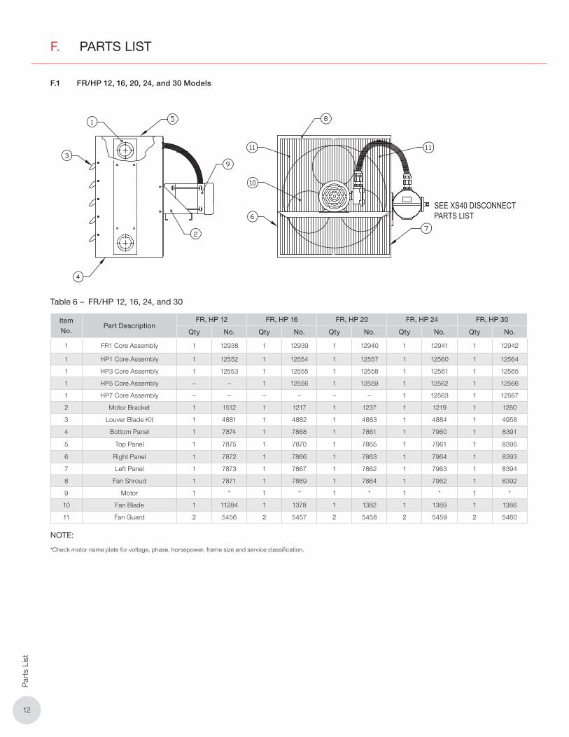
F.1 FR/HP 12, 16, 20, 24, and 30 Models
SEE XS40 DISCONNECTPARTS LIST
Table 6 – FR/HP 12, 16, 24, and 30
Item
No.Part Description
FR, HP 12 FR, HP 16 FR, HP 20 FR, HP 24 FR, HP 30
Qty No. Qty No. Qty No. Qty No. Qty No.
1 FR1 Core Assembly 1 12938 1 12939 1 12940 1 12941 1 12942
1 HP1 Core Assembly 1 12552 1 12554 1 12557 1 12560 1 12564
1 HP3 Core Assembly 1 12553 1 12555 1 12558 1 12561 1 12565
1 HP5 Core Assembly – – 1 12556 1 12559 1 12562 1 12566
1 HP7 Core Assembly – – – – – – 1 12563 1 12567
2 Motor Bracket 1 1512 1 1217 1 1237 1 1219 1 1280
3 Louver Blade Kit 1 4881 1 4882 1 4883 1 4884 1 4958
4 Bottom Panel 1 7874 1 7868 1 7861 1 7960 1 8391
5 Top Panel 1 7875 1 7870 1 7865 1 7961 1 8395
6 Right Panel 1 7872 1 7866 1 7863 1 7964 1 8393
7 Left Panel 1 7873 1 7867 1 7862 1 7963 1 8394
8 Fan Shroud 1 7871 1 7869 1 7864 1 7962 1 8392
9 Motor 1 * 1 * 1 * 1 * 1 *
10 Fan Blade 1 11284 1 1378 1 1382 1 1389 1 1386
11 Fan Guard 2 5456 2 5457 2 5458 2 5459 2 5460
NOTE:
*Check motor name plate for voltage, phase, horsepower, frame size and service classification.
1313
Parts List
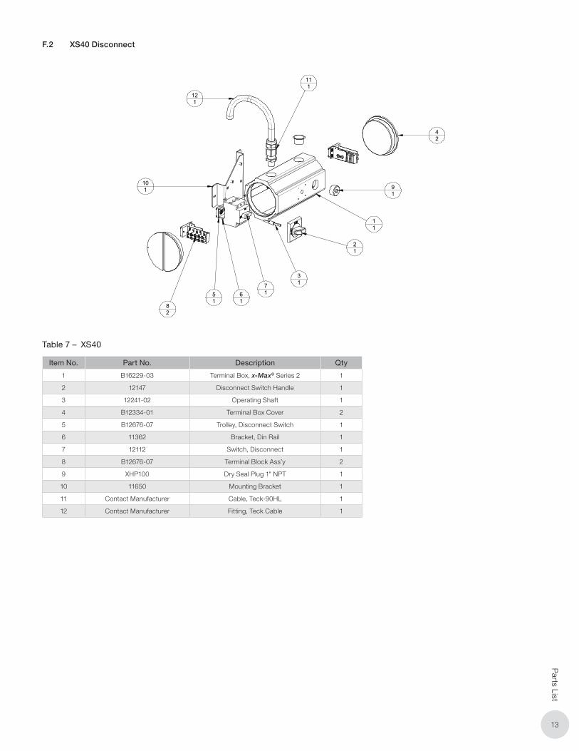
F.2 XS40 Disconnect
XS40
KIT, XS40 DISC SWTCH ASSM
ANGULAR
CHK'D BY:
APP'D. BY:
SCALE:
DRN BY:
±DWG NO.:
TITLE:
SYTELINE NO.: METRIC
TOLERANCE UNLESS NOTED OTHERWISE
DECIMAL FRACTIONAL
REVISION DESCRIPTIONREV. BYDATE
1/2° 0.005" 1/16" 1 mmSHEET:
XS40
lbrauer 19 Dec 2013
± ± ±
SCALE
EDMONTON, ALBERTA
1 OF 1
61
21
101
11
71
91
42
51
82
31
111
121
Item Number Part Number Description Quantity
1 B16229-03 Terminal Box, X-max Series 2 1
2 12147 Disconnect Switch Handle 1
3 12241-02 Operating Shaft 1
4 B12334-01 Terminal Box Cover 2
5 B12676-07 Trolley, Disconnect Switch 1
6 11362 Bracket, Din Rail 1
7 12112 Switch, Disconnect 1
8 B12676-07 Terminal Block Ass'y 2
9 XHP100 Dry Seal Plug 1" NPT 1
10 11650 Mounting Bracket 1
11 Contact Manufactuer Cable, Teck-90HL 1
12 Contact Manufacturer Fitting, Teck Cable 1
Table 7 – XS40
Item No. Part No. Description Qty
1 B16229-03 Terminal Box, x-Max® Series 2 1
2 12147 Disconnect Switch Handle 1
3 12241-02 Operating Shaft 1
4 B12334-01 Terminal Box Cover 2
5 B12676-07 Trolley, Disconnect Switch 1
6 11362 Bracket, Din Rail 1
7 12112 Switch, Disconnect 1
8 B12676-07 Terminal Block Ass’y 2
9 XHP100 Dry Seal Plug 1" NPT 1
10 11650 Mounting Bracket 1
11 Contact Manufacturer Cable, Teck-90HL 1
12 Contact Manufacturer Fitting, Teck Cable 1

1414
Par
ts L
ist
F.3 FR/HP 36 Models
1 8 15
16
7
10 11 14 17
12
5 13 9
26
4
3
11
PARTS LISTFR/HP 36 models
ITEM PART FR, HP36
NO. DESCRIPTION QTY NUMBER
1 FR1 CORE ASSEMBLY 1 2058
1 HP1 CORE ASSEMBLY 1 2044
1 HP3 CORE ASSEMBLY 1 2049
1 HP5 CORE ASSEMBLY 1 2050
1 HP7 CORE ASSEMBLY 1 2189
2 MOTOR BRACKET 1 3426
3 LOUVER BLADE KIT 1 4959
4 BOTTOM COVER 1 1233
5 MOTOR 1 --**--
6 U-CLIPS 2 3444
7 FAN BLADE 1 1395
ITEM PART FR, HP36
NO. DESCRIPTION QTY NUMBER
8 FAN GUARD FRAME 1 3443
9 TAPER BUSHING, DRIVE 1 -- * --
10 DRIVEN SHEAVE 1 1398
11 1” TAPER BUSHING, DRIVEN 1 1401
12 V-BELT 1 1402
13 DRIVE SHEAVE 1 1399
14 BEARING 1” PILLOW BLOCK 2 1396
15 FAN GUARD, UPPER PANEL 1 3455
16 FRAME, 36 FAN DRIVE 1 3424
17 SHAFT 1 1268
Note:*Specify shaft diameter when ordering.** Check motor name plate for voltage, phase, H.P., frame size and service classification.
Table 8 – FR/HP 36
Item No. Part DescriptionFR, HP 36
Qty No.
1 FR1 Core Assembly 1 12943
1 HP1 Core Assembly 1 12568
1 HP3 Core Assembly 1 12569
1 HP5 Core Assembly 1 12570
1 HP7 Core Assembly 1 12571
2 Motor Bracket 1 3426
3 Louver Blade Kit 1 4959
4 Bottom Panel 1 1233
5 Motor 1 *
6 U-Clips 2 3444
7 Fan Blade 1 1395
8 Fan Guard Frame 1 3443
9 Taper Busing, Drive 1 **
10 Drive Sheave 1 1398
11 1" Taper Busing, Driven 1 1401
12 V-belt 1 1402
13 Drive Sheave 1 1399
14 Bearing 1" Pillow Block 2 1396
15 Fan Guard, Upper 1 3455
16 Frame, 36 Fan Drive 1 3424
17 Shaft 1 1268
NOTE:
*Check motor name plate for voltage, phase, horsepower, frame size and service classification.
**Specify shaft diameter when ordering.
1515
Model C
oding
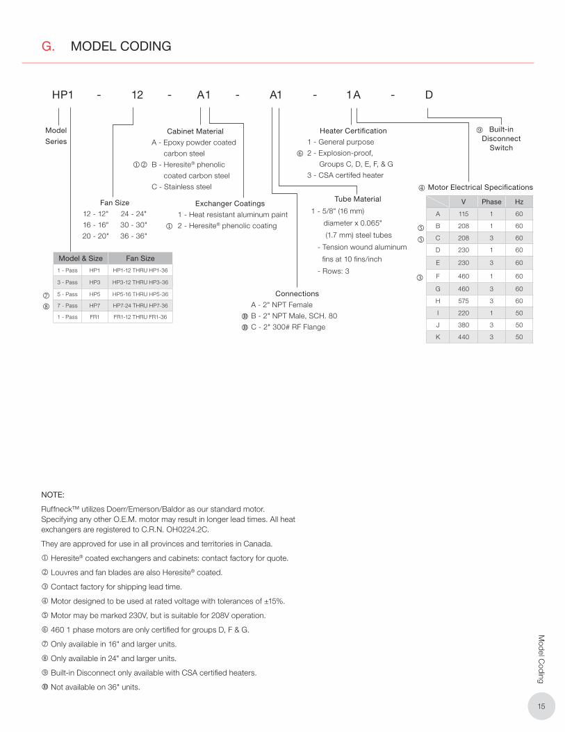
G. MODEL CODING
HP1 - 12 - A1 - A1 - 1A - D
Model
Series
Fan Size
12 - 12"
16 - 16"
20 - 20"
24 - 24"
30 - 30"
36 - 36"
Cabinet Material
A - Epoxy powder coated
carbon steel
B - Heresite® phenolic
coated carbon steel
C - Stainless steel
Exchanger Coatings
1 - Heat resistant aluminum paint
2 - Heresite® phenolic coating
Tube Material
1 - 5/8" (16 mm)
diameter x 0.065"
(1.7 mm) steel tubes
- Tension wound aluminum
fi ns at 10 fi ns/inch
- Rows: 3
Model Coding
Heater Certifi cation
1 - General purpose
2 - Explosion-proof,
Groups C, D, E, F, & G
3 - CSA certifed heater
Model & Size Fan Size
1 - Pass HP1 HP1-12 THRU HP1-36
3 - Pass HP3 HP3-12 THRU HP3-36
5 - Pass HP5 HP5-16 THRU HP5-36
7 - Pass HP7 HP7-24 THRU HP7-36
1 - Pass FR1 FR1-12 THRU FR1-36
Built-in Disconnect
Switch
NOTE:
Ruffneck™ utilizes Doerr/Emerson/Baldor as our standard motor. Specifying any other O.E.M. motor may result in longer lead times. All heat exchangers are registered to C.R.N. OH0224.2C.
They are approved for use in all provinces and territories in Canada.
Heresite® coated exchangers and cabinets: contact factory for quote.
Louvres and fan blades are also Heresite® coated.
Contact factory for shipping lead time.
Motor designed to be used at rated voltage with tolerances of ±15%.
Motor may be marked 230V, but is suitable for 208V operation.
460 1 phase motors are only certifi ed for groups D, F & G.
Only available in 16" and larger units.
Only available in 24" and larger units.
Built-in Disconnect only available with CSA certifi ed heaters.
Not available on 36" units.
V Phase Hz
A 115 1 60
B 208 1 60
C 208 3 60
D 230 1 60
E 230 3 60
F 460 1 60
G 460 3 60
H 575 3 60
I 220 1 50
J 380 3 50
K 440 3 50
Motor Electrical Specifi cations
Connections
A - 2" NPT Female
B - 2" NPT Male, SCH. 80
C - 2" 300# RF Flange
PLEASE ADHERE TO INSTRUCTIONS IN THIS MANUAL
Failure to do so may be dangerous and may void certain provisions of
your warranty.
For further assistance, please call 24hr hotline: 1-800-661-8529 (U.S.A. and Canada)
Please have model and serial numbers available before calling.
Oakville
1-800-410-3131
1-905-829-4422
F 905-829-4430
Orillia
1-877-325-3473
1-705-325-3473
F 705-325-2106
WARRANTY: Under normal use the Company warrants to
the purchaser that defects in material or workmanship will be
repaired or replaced without charge for a period of 18 months
from date of shipment, or 12 months from the start date of
operation, whichever expires fi rst. Any claim for warranty must
be reported to the sales offi ce where the product was purchased
for authorized repair or replacement within the terms of this
warranty.
Subject to State or Provincial law to the contrary, the Company
will not be responsible for any expense for installation, removal
from service, transportation, or damages of any type whatsoever,
including damages arising from lack of use, business interruptions,
or incidental or consequential damages.
The Company cannot anticipate or control the conditions of
product usage and therefore accepts no responsibility for
the safe application and suitability of its products when used
alone or in combination with other products. Tests for the
safe application and suitability of the products are the sole
responsibility of the user.
This warranty will be void if, in the judgment of the Company,
the damage, failure or defect is the result of:
• Vibration, radiation, erosion, corrosion, process
contamination, abnormal process conditions, temperature
and pressures, unusual surges or pulsation, fouling,
ordinary wear and tear, lack of maintenance, incorrectly
applied utilities such as voltage, air, gas, water, and others
or any combination of the aforementioned causes not
specifi cally allowed for in the design conditions or,
• Any act or omission by the Purchaser, its agents, servants
or independent contractors which for greater certainty, but
not so as to limit the generality of the foregoing, includes
physical, chemical or mechanical abuse, accident,
improper installation of the product, improper storage
and handling of the product, improper application or the
misalignment of parts.
No warranty applies to paint fi nishes except for manufacturing defects
apparent within 30 days from the date of installation.
The Company neither assumes nor authorizes any person to assume for it
any other obligation or liability in connection with the product(s).
The Purchaser agrees that all warranty work required after the initial
commissioning of the product will be provided only if the Company
has been paid by the Purchaser in full accordance with the terms and
conditions of the contract.
The Purchaser agrees that the Company makes no warranty or
guarantee, express, implied or statutory, (including any warranty of
merchantability or warranty of fi tness for a particular purpose) written
or oral, of the Article or incidental labour, except as is expressed or
contained in the agreement herein.
LIABILITY: Technical data contained in the catalog or on the
website is subject to change without notice. The Company reserves
the right to make dimensional and other design changes as required.
The Purchaser acknowledges the Company shall not be obligated
to modify those articles manufactured before the formulation of the
changes in design or improvements of the products by the Company.
The Company shall not be liable to compensate or indemnify the
Purchaser, end user or any other party against any actions, claims,
liabilities, injury, loss, loss of use, loss of business, damages, indirect
or consequential damages, demands, penalties, fi nes, expenses
(including legal expenses), costs, obligations and causes of action of
any kind arising wholly or partly from negligence or omission of the
user or the misuse, incorrect application, unsafe application, incorrect
storage and handling, incorrect installation, lack of maintenance,
improper maintenance or improper operation of products furnished
by the Company.
Edmonton
1-780-466-3178
F 780-468-5904
5918 Roper Road
Alberta, Canada T6B 3E1
Houston
1-855-219-2101
1-281-506-2310
F 281-506-2316
Denver
1-855-244-3128
1-303-979-7339
F 303-979-7350
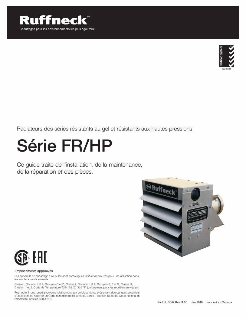
Chauffages pour les environnements les plus rigoureux
MC
Part No.5347.Rev.11.05 Jan 2018 Imprimé au Canada
Série FR/HPRadiateurs des séries résistants au gel et résistants aux hautes pressions
Ce guide traite de l’installation, de la maintenance, de la réparation et des pièces.
ISO 9001
®
Emplacements approuvés
Les appareils de chauffage à air pulsé sont homologués CSA et approuvés pour une utilisation dans les emplacements suivants :
Classe I, Division 1 et 2, Groupes C et D; Classe II, Division 1 et 2, Groupes E, F et G; Classe III, Division 1 et 2; Code de Température T3B 165 °C (329 °F) (uniquement pour les modèles en vigueur)
Pour obtenir des renseignements relativement aux emplacements présentant des dangers potentiels d’explosion, se reporter au Code canadien de l’électricité, partie I, section 18, ou au Code national de l’électricité, articles 500 à 516.
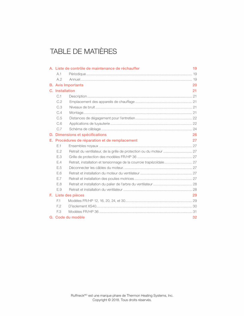
A. Liste de contrôle de maintenance de réchauffer 19A.1 Périodique .......................................................................................................... 19
A.2 Annuel ................................................................................................................ 19
B. Avis Importants 20
C. Installation 21C.1 Description ......................................................................................................... 21
C.2 Emplacement des appareils de chauffage ......................................................... 21
C.3 Niveaux de bruit ................................................................................................. 21
C.4 Montage ............................................................................................................. 21
C.5 Distances de dégagement pour l’entretien ......................................................... 22
C.6 Applications de tuyauterie .................................................................................. 22
C.7 Schéma de câblage ........................................................................................... 24
D. Dimensions et spécifications 26
E. Procédures de réparation et de remplacement 27E.1 Ensembles noyaux ............................................................................................. 27
E.2 Retrait du ventilateur, de la grille de protection ou du moteur ............................. 27
E.3 Grille de protection des modèles FR/HP 36 ....................................................... 27
E.4 Retrait, installation et tensionnage de la courroie trapézoïdale ............................ 27
E.5 Déconnecter les câbles du moteur. .................................................................... 27
E.6 Retrait et installation du moteur du ventilateur .................................................... 27
E.7 Retrait et installation des poulies motrices .......................................................... 27
E.8 Retrait et installation du palier de l’arbre du ventilateur ....................................... 28
E.9 Retrait et installation du ventilateur ..................................................................... 28
F. Liste des pièces 29F.1 Modèles FR/HP 12, 16, 20, 24, et 30 ................................................................... 29
F.2 D’isolement XS40 ................................................................................................ 30
F.3 Modèles FR/HP 36 ............................................................................................. 31
G. Code du modèle 32
RuffneckMC est une marque phare de Thermon Heating Systems, Inc.Copyright © 2018. Tous droits réservés.
TABLE DE MATIÈRES

1919
Liste de contrôle de maintenance de réchauffer
A. LISTE DE CONTRÔLE DE MAINTENANCE DE RÉCHAUFFER
AVERTISSEMENT
AVERTISSEMENT. Débranchez l’appareil de chauffage de la source d’alimentation au moyen du sectionneur intégré ou depuis la boîte à fusibles avant d’ouvrir les connecteurs ou de procéder à l’entretien.
Verrouillez l’interrupteur en position « OFF » (ouvert) ou mettez une étiquette sur l’interrupteur pour éviter d’alimenter l’appareil en puissance de manière inattendue. Pour chauffages
L’entretien de cet appareil de chauffage ne doit être effectué que par du personnel ayant une expérience en appareils de chauffage et en équipement pour emplacements dangereux.
Modèle de réchauffeur
Numéro de serie
Commentaires
Date de maintenance
Maintenance faite par
A.1 Périodique
• Nettoyage
� Tuyaux à ailettes
� Ventilateur
� Grille de protection
� Moteur
� Grilles de transfert
Remarque: Enlever la poussière à l’aide d’air comprimé. Ne pas vaporiser d’eau ou de solvants. Ne pas immerger dans l’eau ou des solvants.
• Vérification
� Fonctionnement régulier et silencieux du moteur
� Angle et serrage appropriés des grilles de transfert
� Serrage de tous les couvercles à l’épreuve des explosions
A.2 Annuel
• Vérification mécanique
� En cas de fuite, débrancher l’appareil de chauffage de sa source d’alimentation et faire remplacer le noyau. Un noyau de remplacement du fabricant peut être expédié immédiatement de l’entrepôt. Se reporter à la section E. Procédures de réparation et de remplacement, page 27pour obtenir de plus amples détails.
� Boîte de jonction électrique. L’intérieur de chaque connecteur doit être propre, sec et libre de corps étrangers Les couvercles filetés doivent être installés et serrés manuellement.
� Jeu et palier de l’arbre de moteur. Remplacer le moteur si le jeu est excessif ou si le moteur ne fonctionne pas silencieusement et régulièrement. Les paliers du moteur sont lubrifiés de manière permanente.
� Ventilateur. Le remplacer immédiatement s’il est craqué ou endommagé.
� Vérifier les grilles de transfert. Les vis des grilles de transfert doivent être bien serrées. Veiller à ne pas fermer les grilles de transfert à plus de 75° de l’horizontal.
� Tout le matériel doit être bien serré. Tous les écrous et boulons, y compris ceux du matériel de montage, doivent être bien serrés.
� Faire fonctionner le moteur de l’appareil de chauffage pendant au moins 15 minutes. S’assurer que l’air est évacué de l’appareil de chauffage au moyen des grilles de transfert et que le moteur du ventilateur fonctionne correctement.
• Vérification électrique
� Tous les connecteurs et conducteurs. Serrer ceux qui sont lâches. Les conducteurs dont l’isolation est endommagée doivent être remplacés.
(avant et au besoin durant la saison de chauffage)
(avant la saison de chauffage)
Pour obtenir de l’aide, veuillez appeler
Sans frais : 1-800-661-8529
États-Unis et Canada
Chauffages pour les environnements les plus rigoureux
2020
Avi
s Im
port
ants
B. AVIS IMPORTANTS
AVERTISSEMENT
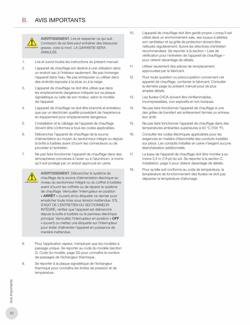
AVERTISSEMENT. Lire et respecter ce qui suit. L’omission de se faire peut entraîner des blessures graves, voire la mort. LA GARANTIE SERA ANNULÉE.
1. Lire et suivre toutes les instructions du présent manuel.
2. L’appareil de chauffage est destiné à une utilisation dans un endroit sec à l’intérieur seulement. Ne pas immerger l’appareil dans l’eau. Ne pas entreposer ou utiliser dans des endroits exposés à la pluie ou à la neige.
3. L’appareil de chauffage ne doit être utilisé que dans les emplacements dangereux indiqués sur sa plaque signalétique ou celle de son moteur, selon le modèle de l’appareil.
4. L’appareil de chauffage ne doit être branché et entretenu que par un électricien qualifié possédant de l’expérience en équipement pour emplacements dangereux.
5. L’installation et le câblage de l’appareil de chauffage doivent être conformes à tous les codes applicables.
6. Débranchez l’appareil de chauffage de la source d’alimentation au moyen du sectionneur intégré ou depuis la boîte à fusibles avant d’ouvrir les connecteurs ou de procéder à l’entretien.
7. Ne pas faire fonctionner l’appareil de chauffage dans des atmosphères corrosives à l’acier ou à l’aluminium, à moins qu’il soit protégé par un enduit approuvé en usine.
AVERTISSEMENT
AVERTISSEMENT. Débrancher le système de chauffage de la source d’alimentation électrique au niveau du sectionneur intégré ou du coffret à fusibles avant d’ouvrir les coffrets ou de réparer le système de chauffage. Verrouiller l’interrupteur en position « ARRÊT » (ouvert) et/ou étiqueter ce dernier pour empêcher toute mise sous tension inattendue. S’IL S’AGIT DE L’ENTRETIEN DU SECTIONNEUR INTÉGRÉ, vérifiez que l’appareil est débranché depuis la boîte à fusibles ou le panneau électrique principal. Verrouillez l’interrupteur en position « OFF » (ouvert) ou mettez une étiquette sur l’interrupteur pour éviter d’alimenter l’appareil en puissance de manière inattendue.
8. Pour l’application vapeur, n’employer que les modèles à passage unique. Se reporter au code du modèle (section G. Code du modèle, page 32) pour connaître le nombre de passages de l’échangeur thermique.
9. Se reporter à la plaque signalétique de l’échangeur thermique pour connaître les limites de pression et de température.
10. L’appareil de chauffage doit être gardé propre. Lorsqu’il est utilisé dans un environnement sale, ses tuyaux à ailettes, son ventilateur et sa grille de protection doivent être nettoyés régulièrement. Suivre les directives d’entretien recommandées. Se reporter à la section « Liste de vérification pour l’entretien de l’appareil de chauffage » pour obtenir davantage de détails.
11. Utiliser seulement des pièces de remplacement approuvées par le fabricant.
12. Pour toute question ou préoccupation concernant cet appareil de chauffage, contacter le fabricant. Consulter la dernière page du présent manuel pour de plus amples détails.
13. Les fluides CVCA doivent être ininflammables, incompressibles, non explosifs et non toxiques.
14. Ne pas faire fonctionner l’appareil de chauffage si une des grilles de transfert est entièrement fermée ou entrave leur arrêt.
15. Ne pas faire fonctionner l’appareil de chauffage dans des températures ambiantes supérieures à 40 °C (104 °F).
16. Consulter les codes électriques applicables pour les exigences en matière d’étanchéité des conduits installés sur place. Les conduits installés en usine n’exigent aucune étanchéisation additionnelle.
17. La base de l’appareil de chauffage doit être montée à au moins 2,4 m (7,9 pi) du sol. Se reporter à la section C. Installation, page 5 pour obtenir davantage de détails.
18. Pour qu’elle soit conforme au code de température, la température de fonctionnement des fluides ne doit pas dépasser la température d’allumage.

2121
Installation
C. INSTALLATION
C.1 Description
Thermon Heating Systems, Inc. offre l’échangeur thermique RuffneckMC en deux configurations de base :
1. Série FR (résistance au gel) : pour application vapeur uniquement, jusqu’à 100 psi (690 kPa) sur certains modèles.
2. Série HP (résistance aux hautes pressions) : pour application vapeur et liquide, jusqu’à 400 psi (2 700 kPa) sur certains modèles.
C.2 Emplacement des appareils de chauffage
1. Thermon Heating Systesms, Inc. a mis en place les directives suivantes afin de vous permettre d’installer les appareils de chauffage à des endroits judicieux dans votre bâtiment. Ce ne sont que des suggestions, et il pourrait être nécessaire de les adapter en fonction de la situation.
2. Si leur principal objectif est d’assurer le confort des occupants, les appareils de chauffage doivent être installés de manière à ce que l’écoulement d’air soit dirigé vers les zones où la perte de chaleur est importante (portes, fenêtres, murs extérieurs, etc.).
3. Si on souhaite plutôt assurer le confort d’un personnel, il faut que la distribution d’air soit stable et uniforme. On optera alors pour l’installation d’un certain nombre de petites unités de chauffage.
4. Lorsque la protection d’un équipement est une priorité absolue, les appareils de chauffage doivent être installés de manière à ce que l’écoulement d’air soit dirigé vers l’équipement en question.
5. Dans les espaces très vastes, les appareils de chauffage doivent être disposés de manière à ce que l’air qui s’échappe d’un appareil soit dirigé vers l’orifice d’entrée ou de sortie d’un autre. Il en résulte-ra un écoulement d’air à vortex qui entraînera une circulation d’air dans la zone centrale du bâtiment.
6. Lors de la disposition des appareils de chauffage à installer, vérifier la portée d’air de leur ventilateur (voir le tableau ci-dessous). Bien qu’il ne soit pas habituellement nécessaire que le flux d’air projeté par un appareil de chauffage atteigne un autre appareil, la circulation d’air doit être suffisante pour empêcher la formation de poches d’air froid.
7. Ne pas installer d’appareils de chauffage de manière à ce que de l’équipement ou des murs nuisent à l’écoulement d’air.
8. Dans le cas d’entrepôts ou de grands ateliers, il peut être judicieux d’opter pour quelques appareils de chauffage de grande taille montés très hauts au-dessus du sol. Il importe toutefois de savoir que seuls les appareils de chauffage de très grande taille sont dotés de ventilateurs ayant une importante portée d’air.
Tableau 1 – Portées d’air des ventilateurs
ModèlePuissance HP
du moteurTr/min
Portée d’air
ft
FR/HP-12 1/2 1725 40
FR/HP-16 1/2 1725 60
FR/HP-20 1/2 1725 65
FR/HP-24 1/2 1725 70
FR/HP-30 3/4 1140 70
FR/HP-36 1 1/2 1725 60
C.3 Niveaux de bruit
Lorsque les employés passent beaucoup de temps dans une pièce ou un bâtiment dont le bruit ambiant est faible, il importe de tenir compte du bruit qu’émettent les appareils de chauffage. De manière générale, plus un appareil de chauffage est de petite taille, moins il sera bruyant. Les appareils de grande taille capables de déplacer d’importants volumes d’air sont considérablement plus bruyants que ceux conçus pour traiter des volumes d’air faibles.
Remarque: Niveaux de bruit mesurés des unités de chauffage à échangeur thermique RuffneckMC
Tableau 2 – Niveaux de bruit mesurés
ModèledBA
Arrière Avant
FR/HP-12 61
FR/HP-16 70
FR/HP-20 66
FR/HP-24 74
FR/HP-30 74
FR/HP-36 76
C.4 Montage
1. Bien que les unités de chauffage RuffneckMC soient conçues pour une installation en position droite et à niveau, il est possible de les disposer dans d’autres positions. Toutefois, pour l’application vapeur, il faut que l’orifice d’entrée soit au-dessus de l’orifice de sortie et que le drainage du dessous du noyau se fasse vers l’orifice de sortie. Les unités de chauffage sont conçues pour être suspendues du haut de l’armoire au moyen de deux ou quatre (selon les modèles) boulons NC de 1,6 cm (5/8 po) vissés dans des trous filetés dans le panneau supérieur de l’armoire. Un soutien structurel adéquat est essentiel à l’installation.

2222
Inst
alla
tion
2. Des trousses d’installation de base (BMK), des trousses d’installation pour suspension (HMK), des trousses d’installation pour suspension et pivotement (SHMK) ou des trousses d’installation murale (WMK) sont offertes pour les appareils de chauffage RuffneckMC. Si la structure désignée n’offre pas un soutien structurel suffisant pour supporter les unités, une solution de rechange adéquate comme la trousse d’installation pour tuyaux (PMK) RuffneckMC permettra une installation et une utilisation sécuritaires de ces dernières. La trousse d’installation HMK est la seule qui convient aux modèles d’appareils de chauffage de 76,2 cm et 91,4 cm (30 po et 36 po).
3. Lorsque les appareils de chauffage se retrouvent dans des installations qui peuvent être relocalisées ou déplacées, comme une plate-forme de forage en mer, il importe de prévoir une structure de montage qui est en mesure de supporter toutes les charges probables. Ces charges probables doivent tenir compte de situations excessives comme les répercussions que peut avoir le déchargement d’un camion, etc. Dans le cas de telles installations, il est recommandé d’utiliser des rondelles de blocage sous les têtes de boulon.
4. Selon l’utilisation que l’on veut en faire, les appareils de chauffage peuvent être montés à n’importe quelle hauteur raisonnable au-dessus du sol. Ils peuvent néanmoins être installés à un niveau bas s’ils se trouvent dans un bâtiment peu fréquenté. S’ils ont comme objectif d’assurer le confort, les appareils de chauffage doivent être installés en hauteur. La hauteur de montage se situe habituellement entre 2,3 m et 3,7 m (entre 7,5 pi et 12 pi). Les appareils de chauffage ho-mologués CSA doivent être montés à une hauteur mi-nimale de 2,4 m (7,9 pi) au-dessus du sol. Tous les ap-pareils de chauffage RuffneckMC sont dotés de grilles de transfert qui permettent un écoulement d’air allant de l’horizontal à un angle de 60 degrés ou à une déflexion importante vers le bas. Il ne faut jamais placer les grilles de transfert à moins de 15 degrés par rapport à la position fermée.
C.5 Distances de dégagement pour l’entretien
Il est important de prévoir une distance de dégage-ment suffisante près de l’appareil de chauffage afin d’en permettre l’entretien. Laisser suffisamment d’espace pour faciliter le remplacement de ventila-teurs ou de moteurs. Pour éviter de bloquer l’air né-cessaire au ventilateur de refroidissement, ne pas pla-cer l’arrière du moteur du ventilateur contre une surface. Il est conseillé de prévoir une distance de dégagement d’au moins 5,1 cm (2 po) entre l’arrière du moteur et l’objet le plus près. Pour pouvoir retirer facilement l’ensemble noyau de l’échangeur ther-mique, il est important de prévoir sous ce dernier une distance de dégagement équivalente à la hauteur de son armoire, plus 5 cm (2 po).
C.6 Applications de tuyauterie
1. Les applications et les dispositions de tuyauterie décrites ci-dessous sont des suggestions. Puisqu’il est impossible d’explorer toutes les applications possibles, veuillez consulter des références détaillées en matière de tuyauterie pour obtenir de plus amples renseignements à ce sujet.
Voir des suggestions de dispositions de tuyauterie.
Lorsque l’appareil est utilisé dans des emplacements dangereux, la température des fluides ne doit pas dépasser la température d’allumage. Opter pour des câbles d’alimentation conçus pour une utilisation à une température de 90 °C (194 °F) ainsi que pour des entrées de câble dont l’indice de protection est de 54 et pouvant être utilisées dans les emplacements dangereux.
L’appareil de chauffage doit être utilisé uniquement dans des atmosphères ayant une température d’allumage supérieure à la température de fonctionnement maximale indiquée sur la plaque signalétique de l’appareil. Se reporter aux codes électriques applicables pour obtenir de l’information supplémentaire.
L’installateur doit fournir des raccords d’étanchéité et des manchons coupe-feu homologués « Ex d » qui correspondent aux groupes de gaz du dispositif.
SHUT-OFF VALVE
PITCH DOWN
UNION
6 in. (152 mm) LONGFULL SIZE DIRT POCKET
RETURNSUPPLY
PITCH DOWN
DRAIN VALVE
AUTOMATICAIR VENTORPETCOCK.
SHUT-OFF VALVE
BALANCING VALVE
UNION
Where heaters are installed in applications that are of a relocatable or transportable nature such as land or offshore drilling rigs, an adequate mounting structure should be supplied to withstand all probable load conditions. Such load conditions should recognize abuse situations such as truck off-loading impacts, etc. It is recommended that lock washers be used beneath the bolt heads for these installations.
Heaters may be mounted at any reasonable height above floor level depending on the purpose of the heater. When equipment is placed in a seldomly occupied building, the heaters may be placed at a low level. When heaters are required to ensure personnel comfort, they should be mounted overhead. Typically, mounting heights range from 7 1/2 feet to 12 feet. All Ruffneck™ heaters have louvers installed that allow air flow to be directed from horizontal to 60 degrees or greater downward deflection. Louvers should never be set to within less than 15 degrees of the closed position.
CLEARANCES FOR MAINTENANCE It is important to provide adequate clearance around the heater for servicing. Allow enough space to permit easy fan or motor replacement. Do not position the back of the fan motor against a surface, as air for the cooling fan will be blocked. It is advisable to leave at least 2” clearance between the rear of the motor and the nearest obstruction. For easy removal of the heat exchanger core assembly, it is important to leave clearance beneath the heater equal to the height of the heater cabinet plus two inches.
PIPING APPLICATIONS
The following piping application and arrangements are only suggestions. Since it is impractical to cover all possible applications, please refer to detailed piping references for more information.
Below are suggested piping arrangements.
NOTES:1. Do not use with fluids corrosive to steel2. Install using proper piping practices.
Alimentation Retour
Pente descendante
Robinet d’arrêt
Pente descendante
Valve de drainage
Évent ou robinet de petit diamètre automatique
Collecteur d’impuretés pleine taille de 15,2 cm (6 po)
Raccord union
Robinet d’équilibrage
Remarque:
1. Ne pas utiliser avec des fluides corrosifs à l’acier.
2. Procéder à l’installation en respectant les pratiques adéquates en matière de tuyauterie.
Raccord union
Robinet d’arrêt
Figure 1 – Connexions de lt’unité de chauffage à la canalisation supérieure

2323
Installation
FIG.2UNIT HEATER CONNECTION
FOR LOW-PRESSURE STEAM,OPEN GRAVITY OR VACUUM
RETURN SYSTEM
NOTES:
1. For medium to high-pressure systems a bucket
or float trap must be used.
2. Do not use with fluids corrosive to steel.
3. Install using proper piping practices
4. In horizontal pipe runs, use eccentric reducers only.
5. Use a properly sized steam trap.
TAP INTO TOP OF MAIN
SHUT-OFF VALVE
UNIONPITCH DOWN
UNION
RETURNMAIN
SHUT-OFFVALVE
FLOAT AND THERMOSTATIC TRAP
STEAM MAIN
UNION
10 IN. Min.(254 mm) FULL SIZE DROP LEG
6 in. (152mm) LONGFULL SIZEDIRT POCKET
UNION
Conduite d’eau dans la partie supérieure de la conduite principale
Robinet d’arrêt
Remarque:
3. Il faut utiliser un purgeur à flotteur ouvert ou fermé dans les systèmes de moyenne à haute pression.
4. Ne pas utiliser avec des fluides corrosifs à l’acier.
5. Procéder à l’installation en respectant les pratiques adéquates en matière de tuyauterie.
6. Utiliser uniquement des réductions excentriques dans les canalisations horizontales.
7. Utiliser un robinet de tirage vapeur de taille adéquate.
Pente descendante
Raccord union
Raccord union
Tuyau de descente pleine taille
Tamis
Raccord unionCanalisation
principale de retour
Flotteur et purgeur thermostatiqueConduite
de vapeur principale Raccord
union
Robinet d’arrêt
6 po min. (15.2 cm)Collecteur d’impuretés pleine taille
10 po min. (25.4 mm)
Figure 2 – Connexion d’une unité de chauffage à un réseau de reprise à vapeur basse pression, à gravité ou à vide.
NOTES:1. This piping arrangement is only for two-position-type
control. Modulating steam control may not provide
sufficient pressure to lift condensate to return main.
2. Do not use with fluids corrosive to steel.
3. Install using proper piping practices.
4. In horizontal pipe runs use eccentric reducers only.
5. Use a properly sized steam trap.
TAP INTO TOP OF MAIN
SHUT-OFF VALVE
UNIONPITCH DOWN
UNION
RETURNMAIN
TAP INTO TOP OF MAINSHUT-OFF VALVE
PITCH DOWN
FULL SIZE DROP LEG10.0 in. Min.(254 mm)
SHUT-OFF VALVE
RETURN MAIN
PITCH DOWN
LIFT NOT TO EXCEED 1 FT FOR EACH POUND PRESSURE DIFFERENCE BETWEEN STEAMAND RETURN MAINS
THERMOSTATIC AIRVENT OR PETCOCK.(INSTALL IF TRAP DOESNOT HAVE AIR VENT)
SHUT-OFFVALVE
FLOAT AND THERMOSTATIC TRAP
STEAM MAIN
UNION
UNION
UNION
UNION
SWING CHECK VALVE
STEAM TRAP WITH AIR VENT
STRAINER AND DRAIN VALVE
6 in. (152mm) LONGFULL SIZEDIRT POCKET
STRAINER
10 IN. Min.(254 mm) FULL SIZE DROP LEG
6 in. (152mm) LONGFULL SIZEDIRT POCKET
UNION
NOTES:1. For medium to high-pressure systems a bucket
or float trap must be used.
2. Do not use with fluids corrosive to steel.
3. Install using proper piping practices
4. In horizontal pipe runs, use eccentric reducers only.
5. Use a properly sized steam trap.
Remarque:
1. Il faut utiliser un purgeur à flotteur ouvert ou fermé dans les systèmes de moyenne à haute pression.
2. Ne pas utiliser avec des fluides corrosifs à l’acier.
3. Procéder à l’installation en respectant les pratiques adéquates en matière de tuyauterie.
4. Utiliser uniquement des réductions excentriques dans les canalisations horizontales.
5. Utiliser un robinet de tirage vapeur de taille adéquate.
Collecteur d’impuretés pleine taille de 15,2 cm (6 po)
Évent ou robinet de petit diamètre thermostatique. (Installer si le purgeur n’est pas doté d’un évent.)
Clapet de non-retour à battants
Raccord union
Raccord union
Pente descendante
Pente descendante
Raccord union
Purgeur vapeur avec évent
Tamis avec robinet de vidange
Robinet d’arrêt
Robinet d’arrêtConduite d’eau dans la partie supérieure de la conduite principale
Canalisation principale de
retour
Tuyau de descente pleine taille 10 po min. (25.4 cm)
Ne dépasse pas 1 ft pour chaque differérence presseur entre
canalisation principale de retour et conduite de vapeur principale.
Figure 3 – Connexions d’une unité de chauffage à des canalisations principales de vapeur et de retour supérieures
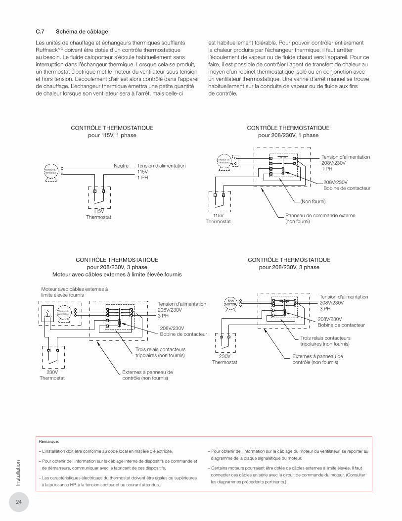
2424
Inst
alla
tion
C.7 Schéma de câblage
Les unités de chauffage et échangeurs thermiques soufflants RuffneckMC doivent être dotés d’un contrôle thermostatique au besoin. Le fluide caloporteur s’écoule habituellement sans interruption dans l’échangeur thermique. Lorsque cela se produit, un thermostat électrique met le moteur du ventilateur sous tension et hors tension. L’écoulement d’air est alors contrôlé dans l’appareil de chauffage. L’échangeur thermique émettra une petite quantité de chaleur lorsque son ventilateur sera à l’arrêt, mais celle-ci
est habituellement tolérable. Pour pouvoir contrôler entièrement la chaleur produite par l’échangeur thermique, il faut arrêter l’écoulement de vapeur ou de fluide chaud vers l’appareil. Pour ce faire, il est possible de contrôler l’agent de transfert de chaleur au moyen d’un robinet thermostatique isolé ou en conjonction avec un ventilateur thermostatique. Une vanne d’arrêt manuel se trouve habituellement sur la conduite de vapeur ou de fluide aux fins de contrôle.
ELECTRICAL WIRING
7
RuffneckTM fan-forced unit heaters and heat exchangers may be thermostatically controlled if required. Usually the flow of heat transfer fluid is allowed to pass through the heat exchanger without interruption. The fan motor, in such cases, shuts on and off by an electrical thermostat. Air flow through the heater is thus controlled. A small amount of heat will radiate from the heat exchanger when the fan is inoperative but this is usually tolerable. Absolute control of heat output from the heat exchanger would require that steam or flow of hot liquid to the heat exchanger be shut off. Such control of the heat transfer medium is possible by thermostatic valve control, separately or in combination with thermostatic fan control. Typically a manual shut-off valve is placed in the steam or liquid line for control purposes.
SUPPLY VOLTAGE208/230V1PH
208/230 VOLTCONTACTOR COIL
(NOT SUPPLIED)
EXTERNAL CONTROL PANEL(NOT SUPPLIED)
230 VOLTTHERMOSTAT
THERMOSTATIC CONTROL FOR208/230 VOLTS, 1 PHASE
THERMOSTATIC CONTROL FOR115 VOLTS, 1 PHASE
THERMOSTATIC CONTROL FOR 208/230 VOLT, 3 PHASE MOTORSC/W EXTERNAL HIGH-LIMIT WIRES
THERMOSTATIC CONTROL FOR208/230 VOLTS, 3 PHASE
THERMOSTATIC CONTROL FOR460/600 VOLTS, 3 PHASE
THERMOSTATIC CONTROL FOR 460/600 VOLT, 3 PHASE MOTORSC/W EXTERNAL HIGH-LIMIT WIRES
FANMOTOR
FANMOTOR
FANMOTOR
FANMOTOR
SUPPLY VOLTAGE115 VOLTS1 PH
NEUTRAL
115 VOLTTHERMOSTAT
SUPPLYVOLTAGE
208/230VOLTS3PH
SUPPLY VOLTAGE208/230 VOLTS 3PH
208/230 VOLTCONTACTOR COIL
3 POLE CONTACTOR RELAY(NOT SUPPLIED)
EXTERNAL CONTROL PANEL(NOT SUPPLIED)
3 POLE CONTACTOR RELAY(NOT SUPPLIED)
SUPPLY VOLTAGE460/6003PH
VOLTAGETRANSFORMER(NOT SUPPLIED)
EXTERNAL CONTROL PANEL(NOT SUPPLIED)
24 TO 230 VOLTTHERMOSTAT
230 VOLTTHERMOSTAT
208/230 VOLTCONTACTOR COIL
MOTOR C/W EXTERNALHIGH-LIMIT WIRES
230 VOLTTHERMOSTAT
EXTERNAL CONTROL PANEL(NOT SUPPLIED)
SUPPLY VOLTAGE460/600VOLTS3PH
EXTERNAL CONTROL PANEL(NOT SUPPLIED)
VOLTAGETRANSFORMER(NOT SUPPLIED)
24 TO 230 VOLTTHERMOSTAT
3 POLE CONTACTOR RELAY(NOT SUPPLIED)MOTOR C/W EXTERNAL
HIGH-LIMIT WIRES
3 POLE CONTACTOR RELAY(NOT SUPPLIED)
FANMOTOR
FANMOTOR
24 TO 230VOLTS
24 TO 230VOLTS
NOTES:- Installation must comply with local electrical code.- For internal wiring of control devices and starters, consult device manufacturer.- The thermostat must have an electrical rating equal to or exceeding the HP, line voltage and current expected.- For wiring of fan motor, refer to diagram on the motor name plate.- Some motors may be equipped with external high-limit wires. These wires must be connected in series with the motor control circuit. (see appropriate diagrams above)
CONTRÔLE THERMOSTATIQUE pour 115V, 1 phase
Moteur du ventilateur
Neutre Tension d’alimentation115V 1 PH
115V Thermostat
ELECTRICAL WIRING
7
RuffneckTM fan-forced unit heaters and heat exchangers may be thermostatically controlled if required. Usually the flow of heat transfer fluid is allowed to pass through the heat exchanger without interruption. The fan motor, in such cases, shuts on and off by an electrical thermostat. Air flow through the heater is thus controlled. A small amount of heat will radiate from the heat exchanger when the fan is inoperative but this is usually tolerable. Absolute control of heat output from the heat exchanger would require that steam or flow of hot liquid to the heat exchanger be shut off. Such control of the heat transfer medium is possible by thermostatic valve control, separately or in combination with thermostatic fan control. Typically a manual shut-off valve is placed in the steam or liquid line for control purposes.
SUPPLY VOLTAGE208/230V1PH
208/230 VOLTCONTACTOR COIL
(NOT SUPPLIED)
EXTERNAL CONTROL PANEL(NOT SUPPLIED)
230 VOLTTHERMOSTAT
THERMOSTATIC CONTROL FOR208/230 VOLTS, 1 PHASE
THERMOSTATIC CONTROL FOR115 VOLTS, 1 PHASE
THERMOSTATIC CONTROL FOR 208/230 VOLT, 3 PHASE MOTORSC/W EXTERNAL HIGH-LIMIT WIRES
THERMOSTATIC CONTROL FOR208/230 VOLTS, 3 PHASE
THERMOSTATIC CONTROL FOR460/600 VOLTS, 3 PHASE
THERMOSTATIC CONTROL FOR 460/600 VOLT, 3 PHASE MOTORSC/W EXTERNAL HIGH-LIMIT WIRES
FANMOTOR
FANMOTOR
FANMOTOR
FANMOTOR
SUPPLY VOLTAGE115 VOLTS1 PH
NEUTRAL
115 VOLTTHERMOSTAT
SUPPLYVOLTAGE
208/230VOLTS3PH
SUPPLY VOLTAGE208/230 VOLTS 3PH
208/230 VOLTCONTACTOR COIL
3 POLE CONTACTOR RELAY(NOT SUPPLIED)
EXTERNAL CONTROL PANEL(NOT SUPPLIED)
3 POLE CONTACTOR RELAY(NOT SUPPLIED)
SUPPLY VOLTAGE460/6003PH
VOLTAGETRANSFORMER(NOT SUPPLIED)
EXTERNAL CONTROL PANEL(NOT SUPPLIED)
24 TO 230 VOLTTHERMOSTAT
230 VOLTTHERMOSTAT
208/230 VOLTCONTACTOR COIL
MOTOR C/W EXTERNALHIGH-LIMIT WIRES
230 VOLTTHERMOSTAT
EXTERNAL CONTROL PANEL(NOT SUPPLIED)
SUPPLY VOLTAGE460/600VOLTS3PH
EXTERNAL CONTROL PANEL(NOT SUPPLIED)
VOLTAGETRANSFORMER(NOT SUPPLIED)
24 TO 230 VOLTTHERMOSTAT
3 POLE CONTACTOR RELAY(NOT SUPPLIED)MOTOR C/W EXTERNAL
HIGH-LIMIT WIRES
3 POLE CONTACTOR RELAY(NOT SUPPLIED)
FANMOTOR
FANMOTOR
24 TO 230VOLTS
24 TO 230VOLTS
NOTES:- Installation must comply with local electrical code.- For internal wiring of control devices and starters, consult device manufacturer.- The thermostat must have an electrical rating equal to or exceeding the HP, line voltage and current expected.- For wiring of fan motor, refer to diagram on the motor name plate.- Some motors may be equipped with external high-limit wires. These wires must be connected in series with the motor control circuit. (see appropriate diagrams above)
CONTRÔLE THERMOSTATIQUE pour 208/230V, 1 phase
Moteur du ventilateur
Tension d’alimentation208V/230V1 PH
115V Thermostat
Panneau de commande externe (non fourni)
(Non fourni)
208V/230V Bobine de contacteur
ELECTRICAL WIRING
7
RuffneckTM fan-forced unit heaters and heat exchangers may be thermostatically controlled if required. Usually the flow of heat transfer fluid is allowed to pass through the heat exchanger without interruption. The fan motor, in such cases, shuts on and off by an electrical thermostat. Air flow through the heater is thus controlled. A small amount of heat will radiate from the heat exchanger when the fan is inoperative but this is usually tolerable. Absolute control of heat output from the heat exchanger would require that steam or flow of hot liquid to the heat exchanger be shut off. Such control of the heat transfer medium is possible by thermostatic valve control, separately or in combination with thermostatic fan control. Typically a manual shut-off valve is placed in the steam or liquid line for control purposes.
SUPPLY VOLTAGE208/230V1PH
208/230 VOLTCONTACTOR COIL
(NOT SUPPLIED)
EXTERNAL CONTROL PANEL(NOT SUPPLIED)
230 VOLTTHERMOSTAT
THERMOSTATIC CONTROL FOR208/230 VOLTS, 1 PHASE
THERMOSTATIC CONTROL FOR115 VOLTS, 1 PHASE
THERMOSTATIC CONTROL FOR 208/230 VOLT, 3 PHASE MOTORSC/W EXTERNAL HIGH-LIMIT WIRES
THERMOSTATIC CONTROL FOR208/230 VOLTS, 3 PHASE
THERMOSTATIC CONTROL FOR460/600 VOLTS, 3 PHASE
THERMOSTATIC CONTROL FOR 460/600 VOLT, 3 PHASE MOTORSC/W EXTERNAL HIGH-LIMIT WIRES
FANMOTOR
FANMOTOR
FANMOTOR
FANMOTOR
SUPPLY VOLTAGE115 VOLTS1 PH
NEUTRAL
115 VOLTTHERMOSTAT
SUPPLYVOLTAGE
208/230VOLTS3PH
SUPPLY VOLTAGE208/230 VOLTS 3PH
208/230 VOLTCONTACTOR COIL
3 POLE CONTACTOR RELAY(NOT SUPPLIED)
EXTERNAL CONTROL PANEL(NOT SUPPLIED)
3 POLE CONTACTOR RELAY(NOT SUPPLIED)
SUPPLY VOLTAGE460/6003PH
VOLTAGETRANSFORMER(NOT SUPPLIED)
EXTERNAL CONTROL PANEL(NOT SUPPLIED)
24 TO 230 VOLTTHERMOSTAT
230 VOLTTHERMOSTAT
208/230 VOLTCONTACTOR COIL
MOTOR C/W EXTERNALHIGH-LIMIT WIRES
230 VOLTTHERMOSTAT
EXTERNAL CONTROL PANEL(NOT SUPPLIED)
SUPPLY VOLTAGE460/600VOLTS3PH
EXTERNAL CONTROL PANEL(NOT SUPPLIED)
VOLTAGETRANSFORMER(NOT SUPPLIED)
24 TO 230 VOLTTHERMOSTAT
3 POLE CONTACTOR RELAY(NOT SUPPLIED)MOTOR C/W EXTERNAL
HIGH-LIMIT WIRES
3 POLE CONTACTOR RELAY(NOT SUPPLIED)
FANMOTOR
FANMOTOR
24 TO 230VOLTS
24 TO 230VOLTS
NOTES:- Installation must comply with local electrical code.- For internal wiring of control devices and starters, consult device manufacturer.- The thermostat must have an electrical rating equal to or exceeding the HP, line voltage and current expected.- For wiring of fan motor, refer to diagram on the motor name plate.- Some motors may be equipped with external high-limit wires. These wires must be connected in series with the motor control circuit. (see appropriate diagrams above)
CONTRÔLE THERMOSTATIQUEpour 208/230V, 3 phase
Tension d’alimentation208V/230V3 PH
208V/230V Bobine de contacteur
230V Thermostat
Trois relais contacteurs tripolaires (non fournis)
Externes à panneau de contrôle (non fournis)
ELECTRICAL WIRING
7
RuffneckTM fan-forced unit heaters and heat exchangers may be thermostatically controlled if required. Usually the flow of heat transfer fluid is allowed to pass through the heat exchanger without interruption. The fan motor, in such cases, shuts on and off by an electrical thermostat. Air flow through the heater is thus controlled. A small amount of heat will radiate from the heat exchanger when the fan is inoperative but this is usually tolerable. Absolute control of heat output from the heat exchanger would require that steam or flow of hot liquid to the heat exchanger be shut off. Such control of the heat transfer medium is possible by thermostatic valve control, separately or in combination with thermostatic fan control. Typically a manual shut-off valve is placed in the steam or liquid line for control purposes.
SUPPLY VOLTAGE208/230V1PH
208/230 VOLTCONTACTOR COIL
(NOT SUPPLIED)
EXTERNAL CONTROL PANEL(NOT SUPPLIED)
230 VOLTTHERMOSTAT
THERMOSTATIC CONTROL FOR208/230 VOLTS, 1 PHASE
THERMOSTATIC CONTROL FOR115 VOLTS, 1 PHASE
THERMOSTATIC CONTROL FOR 208/230 VOLT, 3 PHASE MOTORSC/W EXTERNAL HIGH-LIMIT WIRES
THERMOSTATIC CONTROL FOR208/230 VOLTS, 3 PHASE
THERMOSTATIC CONTROL FOR460/600 VOLTS, 3 PHASE
THERMOSTATIC CONTROL FOR 460/600 VOLT, 3 PHASE MOTORSC/W EXTERNAL HIGH-LIMIT WIRES
FANMOTOR
FANMOTOR
FANMOTOR
FANMOTOR
SUPPLY VOLTAGE115 VOLTS1 PH
NEUTRAL
115 VOLTTHERMOSTAT
SUPPLYVOLTAGE
208/230VOLTS3PH
SUPPLY VOLTAGE208/230 VOLTS 3PH
208/230 VOLTCONTACTOR COIL
3 POLE CONTACTOR RELAY(NOT SUPPLIED)
EXTERNAL CONTROL PANEL(NOT SUPPLIED)
3 POLE CONTACTOR RELAY(NOT SUPPLIED)
SUPPLY VOLTAGE460/6003PH
VOLTAGETRANSFORMER(NOT SUPPLIED)
EXTERNAL CONTROL PANEL(NOT SUPPLIED)
24 TO 230 VOLTTHERMOSTAT
230 VOLTTHERMOSTAT
208/230 VOLTCONTACTOR COIL
MOTOR C/W EXTERNALHIGH-LIMIT WIRES
230 VOLTTHERMOSTAT
EXTERNAL CONTROL PANEL(NOT SUPPLIED)
SUPPLY VOLTAGE460/600VOLTS3PH
EXTERNAL CONTROL PANEL(NOT SUPPLIED)
VOLTAGETRANSFORMER(NOT SUPPLIED)
24 TO 230 VOLTTHERMOSTAT
3 POLE CONTACTOR RELAY(NOT SUPPLIED)MOTOR C/W EXTERNAL
HIGH-LIMIT WIRES
3 POLE CONTACTOR RELAY(NOT SUPPLIED)
FANMOTOR
FANMOTOR
24 TO 230VOLTS
24 TO 230VOLTS
NOTES:- Installation must comply with local electrical code.- For internal wiring of control devices and starters, consult device manufacturer.- The thermostat must have an electrical rating equal to or exceeding the HP, line voltage and current expected.- For wiring of fan motor, refer to diagram on the motor name plate.- Some motors may be equipped with external high-limit wires. These wires must be connected in series with the motor control circuit. (see appropriate diagrams above)
230V Thermostat
Moteur du ventilateur
CONTRÔLE THERMOSTATIQUE pour 208/230V, 3 phase
Moteur avec câbles externes à limite élevée fournis
Moteur avec câbles externes à limite élevée fournis
Tension d’alimentation208V/230V3 PH
208V/230V Bobine de contacteur
Trois relais contacteurs tripolaires (non fournis)
Externes à panneau de contrôle (non fournis)
Remarque:
– L’installation doit être conforme au code local en matière d’électricité.
– Pour obtenir de l’information sur le câblage interne de dispositifs de commande et
de démarreurs, communiquer avec le fabricant de ces dispositifs.
– Les caractéristiques électriques du thermostat doivent être égales ou supérieures
à la puissance HP, à la tension secteur et au courant attendus.
– Pour obtenir de l’information sur le câblage du moteur du ventilateur, se reporter au
diagramme de la plaque signalétique du moteur.
– Certains moteurs pourraient être dotés de câbles externes à limite élevée. Il faut
connecter ces câbles en série avec le circuit de commande du moteur. (Consulter
les diagrammes précédents pertinents.)
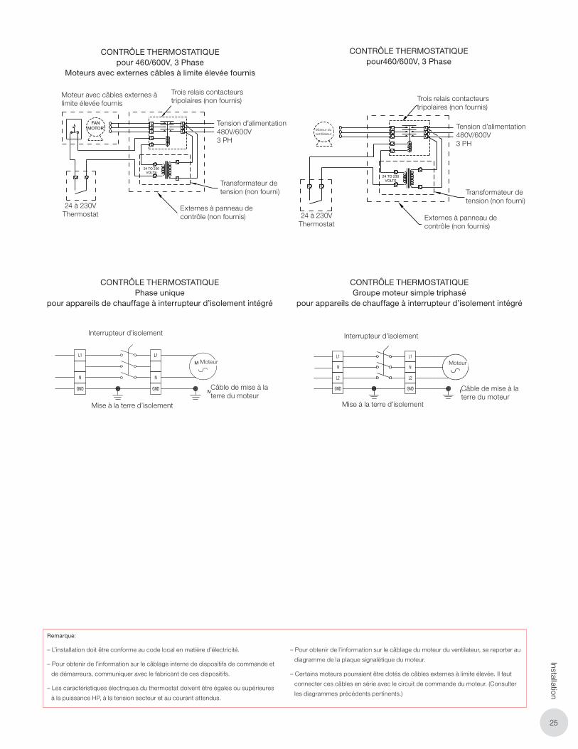
2525
Installation
ELECTRICAL WIRING
7
RuffneckTM fan-forced unit heaters and heat exchangers may be thermostatically controlled if required. Usually the flow of heat transfer fluid is allowed to pass through the heat exchanger without interruption. The fan motor, in such cases, shuts on and off by an electrical thermostat. Air flow through the heater is thus controlled. A small amount of heat will radiate from the heat exchanger when the fan is inoperative but this is usually tolerable. Absolute control of heat output from the heat exchanger would require that steam or flow of hot liquid to the heat exchanger be shut off. Such control of the heat transfer medium is possible by thermostatic valve control, separately or in combination with thermostatic fan control. Typically a manual shut-off valve is placed in the steam or liquid line for control purposes.
SUPPLY VOLTAGE208/230V1PH
208/230 VOLTCONTACTOR COIL
(NOT SUPPLIED)
EXTERNAL CONTROL PANEL(NOT SUPPLIED)
230 VOLTTHERMOSTAT
THERMOSTATIC CONTROL FOR208/230 VOLTS, 1 PHASE
THERMOSTATIC CONTROL FOR115 VOLTS, 1 PHASE
THERMOSTATIC CONTROL FOR 208/230 VOLT, 3 PHASE MOTORSC/W EXTERNAL HIGH-LIMIT WIRES
THERMOSTATIC CONTROL FOR208/230 VOLTS, 3 PHASE
THERMOSTATIC CONTROL FOR460/600 VOLTS, 3 PHASE
THERMOSTATIC CONTROL FOR 460/600 VOLT, 3 PHASE MOTORSC/W EXTERNAL HIGH-LIMIT WIRES
FANMOTOR
FANMOTOR
FANMOTOR
FANMOTOR
SUPPLY VOLTAGE115 VOLTS1 PH
NEUTRAL
115 VOLTTHERMOSTAT
SUPPLYVOLTAGE
208/230VOLTS3PH
SUPPLY VOLTAGE208/230 VOLTS 3PH
208/230 VOLTCONTACTOR COIL
3 POLE CONTACTOR RELAY(NOT SUPPLIED)
EXTERNAL CONTROL PANEL(NOT SUPPLIED)
3 POLE CONTACTOR RELAY(NOT SUPPLIED)
SUPPLY VOLTAGE460/6003PH
VOLTAGETRANSFORMER(NOT SUPPLIED)
EXTERNAL CONTROL PANEL(NOT SUPPLIED)
24 TO 230 VOLTTHERMOSTAT
230 VOLTTHERMOSTAT
208/230 VOLTCONTACTOR COIL
MOTOR C/W EXTERNALHIGH-LIMIT WIRES
230 VOLTTHERMOSTAT
EXTERNAL CONTROL PANEL(NOT SUPPLIED)
SUPPLY VOLTAGE460/600VOLTS3PH
EXTERNAL CONTROL PANEL(NOT SUPPLIED)
VOLTAGETRANSFORMER(NOT SUPPLIED)
24 TO 230 VOLTTHERMOSTAT
3 POLE CONTACTOR RELAY(NOT SUPPLIED)MOTOR C/W EXTERNAL
HIGH-LIMIT WIRES
3 POLE CONTACTOR RELAY(NOT SUPPLIED)
FANMOTOR
FANMOTOR
24 TO 230VOLTS
24 TO 230VOLTS
NOTES:- Installation must comply with local electrical code.- For internal wiring of control devices and starters, consult device manufacturer.- The thermostat must have an electrical rating equal to or exceeding the HP, line voltage and current expected.- For wiring of fan motor, refer to diagram on the motor name plate.- Some motors may be equipped with external high-limit wires. These wires must be connected in series with the motor control circuit. (see appropriate diagrams above)
CONTRÔLE THERMOSTATIQUE pour 460/600V, 3 Phase
Moteurs avec externes câbles à limite élevée fournis
Moteur avec câbles externes à limite élevée fournis
24 à 230V Thermostat
Externes à panneau de contrôle (non fournis)
Tension d’alimentation480V/600V3 PH
Trois relais contacteurs tripolaires (non fournis)
Transformateur de tension (non fourni)
ELECTRICAL WIRING
7
RuffneckTM fan-forced unit heaters and heat exchangers may be thermostatically controlled if required. Usually the flow of heat transfer fluid is allowed to pass through the heat exchanger without interruption. The fan motor, in such cases, shuts on and off by an electrical thermostat. Air flow through the heater is thus controlled. A small amount of heat will radiate from the heat exchanger when the fan is inoperative but this is usually tolerable. Absolute control of heat output from the heat exchanger would require that steam or flow of hot liquid to the heat exchanger be shut off. Such control of the heat transfer medium is possible by thermostatic valve control, separately or in combination with thermostatic fan control. Typically a manual shut-off valve is placed in the steam or liquid line for control purposes.
SUPPLY VOLTAGE208/230V1PH
208/230 VOLTCONTACTOR COIL
(NOT SUPPLIED)
EXTERNAL CONTROL PANEL(NOT SUPPLIED)
230 VOLTTHERMOSTAT
THERMOSTATIC CONTROL FOR208/230 VOLTS, 1 PHASE
THERMOSTATIC CONTROL FOR115 VOLTS, 1 PHASE
THERMOSTATIC CONTROL FOR 208/230 VOLT, 3 PHASE MOTORSC/W EXTERNAL HIGH-LIMIT WIRES
THERMOSTATIC CONTROL FOR208/230 VOLTS, 3 PHASE
THERMOSTATIC CONTROL FOR460/600 VOLTS, 3 PHASE
THERMOSTATIC CONTROL FOR 460/600 VOLT, 3 PHASE MOTORSC/W EXTERNAL HIGH-LIMIT WIRES
FANMOTOR
FANMOTOR
FANMOTOR
FANMOTOR
SUPPLY VOLTAGE115 VOLTS1 PH
NEUTRAL
115 VOLTTHERMOSTAT
SUPPLYVOLTAGE
208/230VOLTS3PH
SUPPLY VOLTAGE208/230 VOLTS 3PH
208/230 VOLTCONTACTOR COIL
3 POLE CONTACTOR RELAY(NOT SUPPLIED)
EXTERNAL CONTROL PANEL(NOT SUPPLIED)
3 POLE CONTACTOR RELAY(NOT SUPPLIED)
SUPPLY VOLTAGE460/6003PH
VOLTAGETRANSFORMER(NOT SUPPLIED)
EXTERNAL CONTROL PANEL(NOT SUPPLIED)
24 TO 230 VOLTTHERMOSTAT
230 VOLTTHERMOSTAT
208/230 VOLTCONTACTOR COIL
MOTOR C/W EXTERNALHIGH-LIMIT WIRES
230 VOLTTHERMOSTAT
EXTERNAL CONTROL PANEL(NOT SUPPLIED)
SUPPLY VOLTAGE460/600VOLTS3PH
EXTERNAL CONTROL PANEL(NOT SUPPLIED)
VOLTAGETRANSFORMER(NOT SUPPLIED)
24 TO 230 VOLTTHERMOSTAT
3 POLE CONTACTOR RELAY(NOT SUPPLIED)MOTOR C/W EXTERNAL
HIGH-LIMIT WIRES
3 POLE CONTACTOR RELAY(NOT SUPPLIED)
FANMOTOR
FANMOTOR
24 TO 230VOLTS
24 TO 230VOLTS
NOTES:- Installation must comply with local electrical code.- For internal wiring of control devices and starters, consult device manufacturer.- The thermostat must have an electrical rating equal to or exceeding the HP, line voltage and current expected.- For wiring of fan motor, refer to diagram on the motor name plate.- Some motors may be equipped with external high-limit wires. These wires must be connected in series with the motor control circuit. (see appropriate diagrams above)
CONTRÔLE THERMOSTATIQUE pour460/600V, 3 Phase
Externes à panneau de contrôle (non fournis)
Tension d’alimentation480V/600V3 PH
Moteur du ventilateur
24 à 230V Thermostat
Trois relais contacteurs tripolaires (non fournis)
Transformateur de tension (non fourni)
CONTRÔLE THERMOSTATIQUEPhase unique
pour appareils de chauffage à interrupteur d’isolement intégré
Mise à la terre d’isolement
Interrupteur d’isolement
Câble de mise à la terre du moteur
Moteur
CONTRÔLE THERMOSTATIQUEGroupe moteur simple triphasé
pour appareils de chauffage à interrupteur d’isolement intégré
Interrupteur d’isolement
Mise à la terre d’isolement
Câble de mise à la terre du moteur
Moteur
Remarque:
– L’installation doit être conforme au code local en matière d’électricité.
– Pour obtenir de l’information sur le câblage interne de dispositifs de commande et
de démarreurs, communiquer avec le fabricant de ces dispositifs.
– Les caractéristiques électriques du thermostat doivent être égales ou supérieures
à la puissance HP, à la tension secteur et au courant attendus.
– Pour obtenir de l’information sur le câblage du moteur du ventilateur, se reporter au
diagramme de la plaque signalétique du moteur.
– Certains moteurs pourraient être dotés de câbles externes à limite élevée. Il faut
connecter ces câbles en série avec le circuit de commande du moteur. (Consulter
les diagrammes précédents pertinents.)
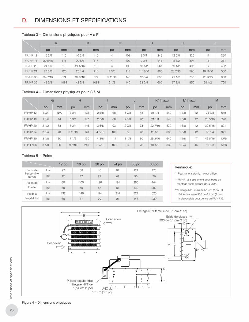
2626
Dim
ensi
ons
et s
péci
ficat
ions
D. DIMENSIONS ET SPÉCIFICATIONS
Tableau 3 – Dimensions physiques pour A à F
A B C D E F
po mm po mm po mm po mm po mm po mm
FR/HP 12 16 5/6 415 16 3/8 416 4 102 9 3/4 248 12 5/8 320 11 280
FR/HP 16 20 5/16 516 20 5/6 517 4 102 9 3/4 248 15 1/2 394 15 381
FR/HP 20 24 5/6 618 24 5/16 618 4 102 10 1/2 267 19 1/2 495 17 432
FR/HP 24 28 3/8 720 28 1/4 718 4 5/8 118 11 13/16 300 23 7/16 596 19 11/16 500
FR/HP 30 34 7/16 874 34 5/16 872 5 11/16 145 13 3/4 350 29 1/2 750 25 9/16 650
FR/HP 36 42 5/8 1083 42 5/8 1083 5 1/2 140 23 5/8 600 37 3/8 950 29 1/2 750
Tableau 4 – Dimensions physiques pour G à M
G H I J K* (max.) L* (max.) M
po mm po mm po mm po mm po mm po mm po mm
FR/HP 12 N/A N/A 6 3/4 172 2 5/8 68 1 7/8 48 21 1/4 540 1 5/8 42 24 3/8 619
FR/HP 16 1 3/4 44 5 3/4 147 2 5/8 68 2 3/4 70 21 1/4 540 1 5/8 42 28 5/16 720
FR/HP 20 2 1/2 63 5 3/4 146 3 5/8 93 2 7/8 73 22 7/16 570 1 5/8 42 32 5/16 821
FR/HP 24 2 3/4 70 6 11/16 170 4 5/16 109 3 76 23 5/8 600 1 5/8 42 36 1/4 921
FR/HP 30 3 1/8 80 7 1/2 190 4 3/8 111 3 1/8 80 25 3/16 640 1 7/8 47 42 5/16 1075
FR/HP 36 3 1/8 80 9 7/16 240 6 7/16 163 3 76 34 5/8 880 1 3/4 45 50 5/8 1286
Tableau 5 – Poids
12 po 16 po 20 po 24 po 30 po 36 po
Poids de l’ensemble
noyau
lbs 27 38 48 91 121 175
kg 12 17 22 41 55 79
Poids de
l’unité
lbs 80 100 126 191 286 444
kg 36 45 57 87 130 202
Poids à
l’expédition
lbs 132 148 174 214 321 526
kg 60 67 79 97 146 239
***Connexion
Connexion
Filetage NPT femelle de 5,1 cm (2 po)
Bride de classe 300 de 5,1 cm (2 po)
UNC de 1,6 cm (5/8 po)
Puissance absorbé filetage NPT de 2,54 cm (1 po)
Figure 4 – Dimensions physiques
Remarque:
* Peut varier selon le moteur utilisé.
** FR/HP 12 a seulement deux trous de
montage sur le desuss de la unité.
*** Filetage NPT mâle de 5,1 cm (2 po) et
Bride de classe 300 de 5,1 cm (2 po)
indisponsible pour unités du FR/HP36.
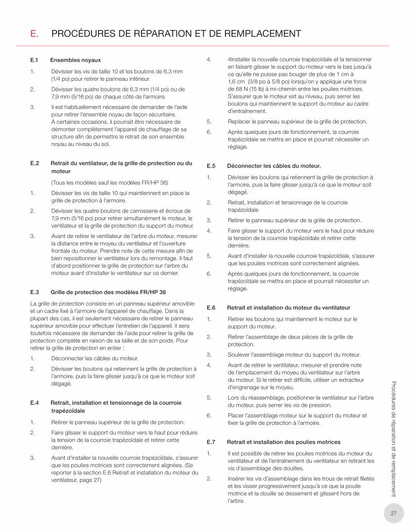
2727
Procédures de réparation et de rem
placement
E. PROCÉDURES DE RÉPARATION ET DE REMPLACEMENT
E.1 Ensembles noyaux
1. Dévisser les vis de taille 10 et les boulons de 6,3 mm (1/4 po) pour retirer le panneau inférieur.
2. Dévisser les quatre boulons de 6,3 mm (1/4 po) ou de 7,9 mm (5/16 po) de chaque côté de l’armoire.
3. Il est habituellement nécessaire de demander de l’aide pour retirer l’ensemble noyau de façon sécuritaire. À certaines occasions, il pourrait être nécessaire de démonter complètement l’appareil de chauffage de sa structure afin de permettre le retrait de son ensemble noyau au niveau du sol.
E.2 Retrait du ventilateur, de la grille de protection ou du moteur
(Tous les modèles sauf les modèles FR/HP 36)
1. Dévisser les vis de taille 10 qui maintiennent en place la grille de protection à l’armoire.
2. Dévisser les quatre boulons de carrosserie et écrous de 7,9 mm (5/16 po) pour retirer simultanément le moteur, le ventilateur et la grille de protection du support du moteur.
3. Avant de retirer le ventilateur de l’arbre du moteur, mesurer la distance entre le moyeu du ventilateur et l’ouverture frontale du moteur. Prendre note de cette mesure afin de bien repositionner le ventilateur lors du remontage. Il faut d’abord positionner la grille de protection sur l’arbre du moteur avant d’installer le ventilateur sur ce dernier.
E.3 Grille de protection des modèles FR/HP 36
La grille de protection consiste en un panneau supérieur amovible et un cadre fixé à l’armoire de l’appareil de chauffage. Dans la plupart des cas, il est seulement nécessaire de retirer le panneau supérieur amovible pour effectuer l’entretien de l’appareil. Il sera toutefois nécessaire de demander de l’aide pour retirer la grille de protection complète en raison de sa taille et de son poids. Pour retirer la grille de protection en entier :
1. Déconnecter les câbles du moteur.
2. Dévisser les boulons qui retiennent la grille de protection à l’armoire, puis la faire glisser jusqu’à ce que le moteur soit dégagé.
E.4 Retrait, installation et tensionnage de la courroie trapézoïdale
1. Retirer le panneau supérieur de la grille de protection.
2. Faire glisser le support du moteur vers le haut pour réduire la tension de la courroie trapézoïdale et retirer cette dernière.
3. Avant d’installer la nouvelle courroie trapézoïdale, s’assurer que les poulies motrices sont correctement alignées. (Se reporter à la section E.6 Retrait et installation du moteur du ventilateur, page 27)
4. 4Installer la nouvelle courroie trapézoïdale et la tensionner en faisant glisser le support du moteur vers le bas jusqu’à ce qu’elle ne puisse pas bouger de plus de 1 cm à 1,6 cm (3/8 po à 5/8 po) lorsqu’on y applique une force de 68 N (15 lb) à mi-chemin entre les poulies motrices. S’assurer que le moteur est au niveau, puis serrer les boulons qui maintiennent le support du moteur au cadre d’entraînement.
5. Replacer le panneau supérieur de la grille de protection.
6. Après quelques jours de fonctionnement, la courroie trapézoïdale se mettra en place et pourrait nécessiter un réglage.
E.5 Déconnecter les câbles du moteur.
1. Dévisser les boulons qui retiennent la grille de protection à l’armoire, puis la faire glisser jusqu’à ce que le moteur soit dégagé.
2. Retrait, installation et tensionnage de la courroie trapézoïdale
3. Retirer le panneau supérieur de la grille de protection.
4. Faire glisser le support du moteur vers le haut pour réduire la tension de la courroie trapézoïdale et retirer cette dernière.
5. Avant d’installer la nouvelle courroie trapézoïdale, s’assurer que les poulies motrices sont correctement alignées.
6. Après quelques jours de fonctionnement, la courroie trapézoïdale se mettra en place et pourrait nécessiter un réglage.
E.6 Retrait et installation du moteur du ventilateur
1. Retirer les boulons qui maintiennent le moteur sur le support du moteur.
2. Retirer l’assemblage de deux pièces de la grille de protection.
3. Soulever l’assemblage moteur du support du moteur.
4. Avant de retirer le ventilateur, mesurer et prendre note de l’emplacement du moyeu du ventilateur sur l’arbre du moteur. Si le retirer est difficile, utiliser un extracteur d’engrenage sur le moyeu.
5. Lors du réassemblage, positionner le ventilateur sur l’arbre du moteur, puis serrer les vis de pression.
6. Placer l’assemblage moteur sur le support du moteur et fixer la grille de protection à l’armoire.
E.7 Retrait et installation des poulies motrices
1. Il est possible de retirer les poulies motrices du moteur du ventilateur et de l’entraînement du ventilateur en retirant les vis d’assemblage des douilles.
2. Insérer les vis d’assemblage dans les trous de retrait filetés et les visser progressivement jusqu’à ce que la poulie motrice et la douille se desserrent et glissent hors de l’arbre.
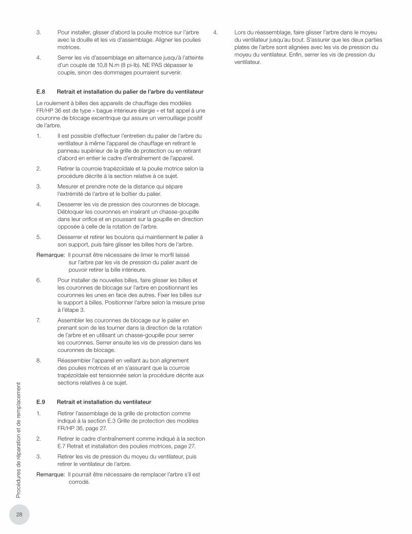
2828
Pro
cédu
res
de r
épar
atio
n et
de
rem
plac
emen
t
3. Pour installer, glisser d’abord la poulie motrice sur l’arbre avec la douille et les vis d’assemblage. Aligner les poulies motrices.
4. Serrer les vis d’assemblage en alternance jusqu’à l’atteinte d’un couple de 10,8 N.m (8 pi-lb). NE PAS dépasser le couple, sinon des dommages pourraient survenir.
E.8 Retrait et installation du palier de l’arbre du ventilateur
Le roulement à billes des appareils de chauffage des modèles FR/HP 36 est de type « bague intérieure élargie » et fait appel à une couronne de blocage excentrique qui assure un verrouillage positif de l’arbre.
1. Il est possible d’effectuer l’entretien du palier de l’arbre du ventilateur à même l’appareil de chauffage en retirant le panneau supérieur de la grille de protection ou en retirant d’abord en entier le cadre d’entraînement de l’appareil.
2. Retirer la courroie trapézoïdale et la poulie motrice selon la procédure décrite à la section relative à ce sujet.
3. Mesurer et prendre note de la distance qui sépare l’extrémité de l’arbre et le boîtier du palier.
4. Desserrer les vis de pression des couronnes de blocage. Débloquer les couronnes en insérant un chasse-goupille dans leur orifice et en poussant sur la goupille en direction opposée à celle de la rotation de l’arbre.
5. Desserrer et retirer les boulons qui maintiennent le palier à son support, puis faire glisser les billes hors de l’arbre.
Remarque: Il pourrait être nécessaire de limer le morfil laissé sur l’arbre par les vis de pression du palier avant de pouvoir retirer la bille intérieure.
6. Pour installer de nouvelles billes, faire glisser les billes et les couronnes de blocage sur l’arbre en positionnant les couronnes les unes en face des autres. Fixer les billes sur le support à billes. Positionner l’arbre selon la mesure prise à l’étape 3.
7. Assembler les couronnes de blocage sur le palier en prenant soin de les tourner dans la direction de la rotation de l’arbre et en utilisant un chasse-goupille pour serrer les couronnes. Serrer ensuite les vis de pression dans les couronnes de blocage.
8. Réassembler l’appareil en veillant au bon alignement des poulies motrices et en s’assurant que la courroie trapézoïdale est tensionnée selon la procédure décrite aux sections relatives à ce sujet.
E.9 Retrait et installation du ventilateur
1. Retirer l’assemblage de la grille de protection comme indiqué à la section E.3 Grille de protection des modèles FR/HP 36, page 27.
2. Retirer le cadre d’entraînement comme indiqué à la section E.7 Retrait et installation des poulies motrices, page 27.
3. Retirer les vis de pression du moyeu du ventilateur, puis retirer le ventilateur de l’arbre.
Remarque: Il pourrait être nécessaire de remplacer l’arbre s’il est corrodé.
4. Lors du réassemblage, faire glisser l’arbre dans le moyeu du ventilateur jusqu’au bout. S’assurer que les deux parties plates de l’arbre sont alignées avec les vis de pression du moyeu du ventilateur. Enfin, serrer les vis de pression du ventilateur.
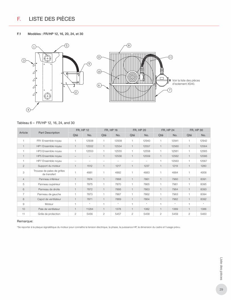
2929
Liste des pièces
F. LISTE DES PIÈCES
F.1 Modèles : FR/HP 12, 16, 20, 24, et 30
SEE XS40 DISCONNECTPARTS LISTVoir la liste des pièces d’isolement XS40.
Tableau 6 – FR/HP 12, 16, 24, and 30
Article Part DescriptionFR, HP 12 FR, HP 16 FR, HP 20 FR, HP 24 FR, HP 30
Qté No. Qté No. Qté No. Qté No. Qté No.
1 FR1 Ensemble noyau 1 12938 1 12939 1 12940 1 12941 1 12942
1 HP1 Ensemble noyau 1 12552 1 12554 1 12557 1 12560 1 12564
1 HP3 Ensemble noyau 1 12553 1 12555 1 12558 1 12561 1 12565
1 HP5 Ensemble noyau – – 1 12556 1 12559 1 12562 1 12566
1 HP7 Ensemble noyau – – – – – – 1 12563 1 12567
2 Support du moteur 1 1512 1 1217 1 1237 1 1219 1 1280
3Trousse de pales de grilles
de transfert1 4881 1 4882 1 4883 1 4884 1 4958
4 Panneau inférieur 1 7874 1 7868 1 7861 1 7960 1 8391
5 Panneau supérieur 1 7875 1 7870 1 7865 1 7961 1 8395
6 Panneau de droite 1 7872 1 7866 1 7863 1 7964 1 8393
7 Panneau de gauche 1 7873 1 7867 1 7862 1 7963 1 8394
8 Capot de ventilateur 1 7871 1 7869 1 7864 1 7962 1 8392
9 Moteur 1 * 1 * 1 * 1 * 1 *
10 Pale de ventilateur 1 11284 1 1378 1 1382 1 1389 1 1386
11 Grille de protection 2 5456 2 5457 2 5458 2 5459 2 5460
Remarque:
*Se reporter à la plaque signalétique du moteur pour connaître la tension électrique, la phase, la puissance HP, la dimension du cadre et l’usage prévu.
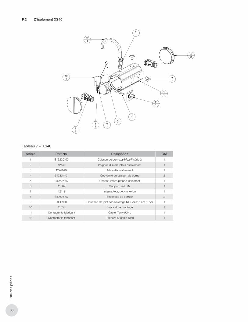
3030
List
e de
s pi
èces
F.2 D’isolement XS40
XS40
KIT, XS40 DISC SWTCH ASSM
ANGULAR
CHK'D BY:
APP'D. BY:
SCALE:
DRN BY:
±DWG NO.:
TITLE:
SYTELINE NO.: METRIC
TOLERANCE UNLESS NOTED OTHERWISE
DECIMAL FRACTIONAL
REVISION DESCRIPTIONREV. BYDATE
1/2° 0.005" 1/16" 1 mmSHEET:
XS40
lbrauer 19 Dec 2013
± ± ±
SCALE
EDMONTON, ALBERTA
1 OF 1
61
21
101
11
71
91
42
51
82
31
111
121
Item Number Part Number Description Quantity
1 B16229-03 Terminal Box, X-max Series 2 1
2 12147 Disconnect Switch Handle 1
3 12241-02 Operating Shaft 1
4 B12334-01 Terminal Box Cover 2
5 B12676-07 Trolley, Disconnect Switch 1
6 11362 Bracket, Din Rail 1
7 12112 Switch, Disconnect 1
8 B12676-07 Terminal Block Ass'y 2
9 XHP100 Dry Seal Plug 1" NPT 1
10 11650 Mounting Bracket 1
11 Contact Manufactuer Cable, Teck-90HL 1
12 Contact Manufacturer Fitting, Teck Cable 1
Tableau 7 – XS40
Article Part No. Description Qté
1 B16229-03 Caisson de borne, x-MaxMD série 2 1
2 12147 Poignée d’interrupteur d’isolement 1
3 12241-02 Arbre d’entraînement 1
4 B12334-01 Couvercle de caisson de borne 2
5 B12676-07 Chariot, interrupteur d’isolement 1
6 11362 Support, rail DIN 1
7 12112 Interrupteur, déconnexion 1
8 B12676-07 Ensemble de bornier 2
9 XHP100 Bouchon de joint sec à filetage NPT de 2,5 cm (1 po) 1
10 11650 Support de montage 1
11 Contacter le fabricant Câble, Teck-90HL 1
12 Contacter le fabricant Raccord et câble Teck 1
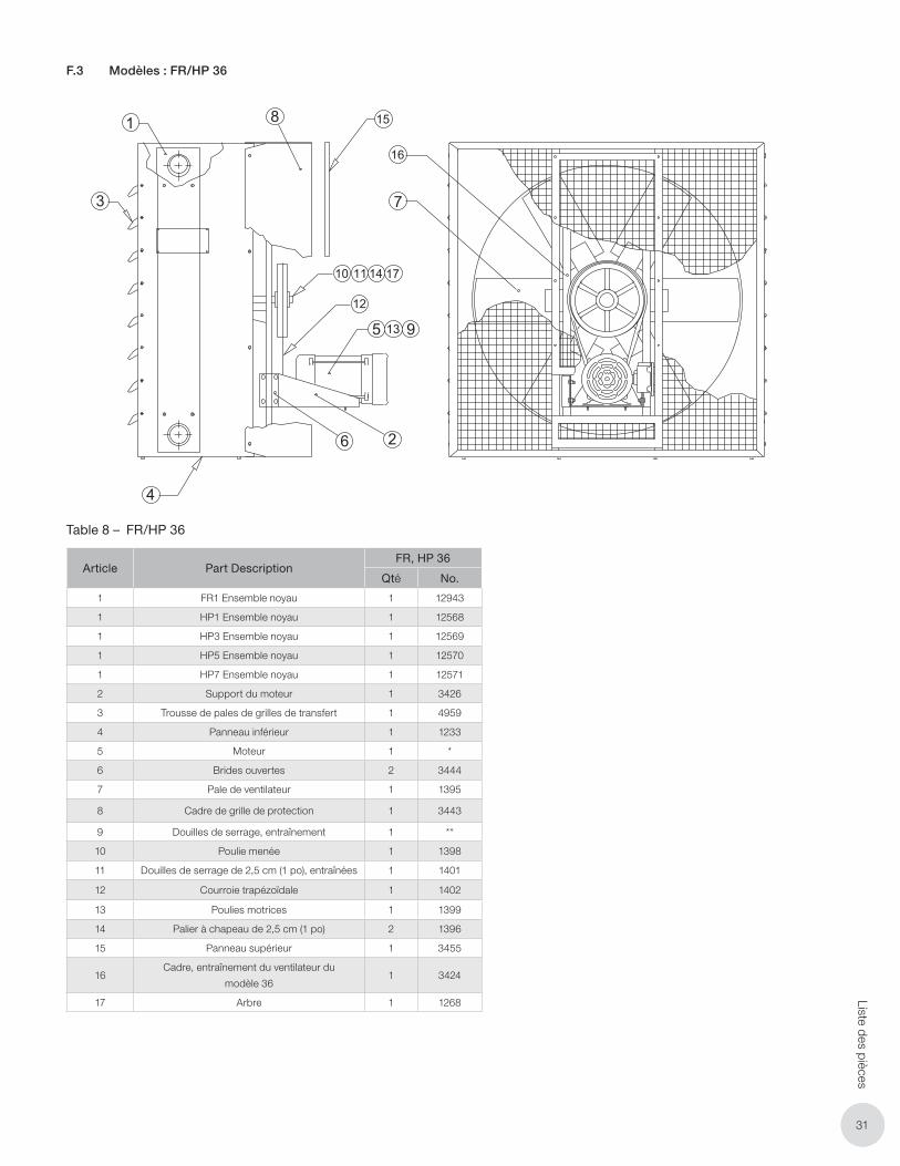
3131
Liste des pièces
F.3 Modèles : FR/HP 36
1 8 15
16
7
10 11 14 17
12
5 13 9
26
4
3
11
PARTS LISTFR/HP 36 models
ITEM PART FR, HP36
NO. DESCRIPTION QTY NUMBER
1 FR1 CORE ASSEMBLY 1 2058
1 HP1 CORE ASSEMBLY 1 2044
1 HP3 CORE ASSEMBLY 1 2049
1 HP5 CORE ASSEMBLY 1 2050
1 HP7 CORE ASSEMBLY 1 2189
2 MOTOR BRACKET 1 3426
3 LOUVER BLADE KIT 1 4959
4 BOTTOM COVER 1 1233
5 MOTOR 1 --**--
6 U-CLIPS 2 3444
7 FAN BLADE 1 1395
ITEM PART FR, HP36
NO. DESCRIPTION QTY NUMBER
8 FAN GUARD FRAME 1 3443
9 TAPER BUSHING, DRIVE 1 -- * --
10 DRIVEN SHEAVE 1 1398
11 1” TAPER BUSHING, DRIVEN 1 1401
12 V-BELT 1 1402
13 DRIVE SHEAVE 1 1399
14 BEARING 1” PILLOW BLOCK 2 1396
15 FAN GUARD, UPPER PANEL 1 3455
16 FRAME, 36 FAN DRIVE 1 3424
17 SHAFT 1 1268
Note:*Specify shaft diameter when ordering.** Check motor name plate for voltage, phase, H.P., frame size and service classification.
Table 8 – FR/HP 36
Article Part DescriptionFR, HP 36
Qté No.
1 FR1 Ensemble noyau 1 12943
1 HP1 Ensemble noyau 1 12568
1 HP3 Ensemble noyau 1 12569
1 HP5 Ensemble noyau 1 12570
1 HP7 Ensemble noyau 1 12571
2 Support du moteur 1 3426
3 Trousse de pales de grilles de transfert 1 4959
4 Panneau inférieur 1 1233
5 Moteur 1 *
6 Brides ouvertes 2 3444
7 Pale de ventilateur 1 1395
8 Cadre de grille de protection 1 3443
9 Douilles de serrage, entraînement 1 **
10 Poulie menée 1 1398
11 Douilles de serrage de 2,5 cm (1 po), entraînées 1 1401
12 Courroie trapézoïdale 1 1402
13 Poulies motrices 1 1399
14 Palier à chapeau de 2,5 cm (1 po) 2 1396
15 Panneau supérieur 1 3455
16Cadre, entraînement du ventilateur du
modèle 361 3424
17 Arbre 1 1268
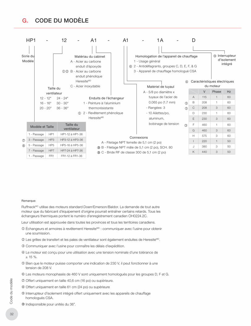
3232
Cod
e du
mod
èle
G. CODE DU MODÈLE
HP1 - 12 - A1 - A1 - 1A - D
Série du
Modèle
Taille du
ventilateur
12 - 12"
16 - 16"
20 - 20"
24 - 24"
30 - 30"
36 - 36"
Matériau du cabinet
A - Acier au carbone
enduit d’époxyde
B - Acier au carbone
enduit phénolique
HeresiteMD
C - Acier inoxydable
Enduits de l’échangeur
1 - Peinture à l’aluminium
thermorésistante
2 - Revêtement phénolique
HeresiteMD
Matériel de tuyaul
A - 5/8 po diamètre x
tuyaux de l’acier de
0.065 po (1.7 mm)
- Rangées: 3
- 10 Ailettes/po,
aluminum,
bobinage de tension
Code du modèle
Connexions
A - Filetage NPT femelle de 5,1 cm (2 po)
B - Filetage NPT mâle de 5,1 cm (2 po), SCH. 80
C - Bride RF de classe 300 de 5,1 cm (2 po)
Homologation de l’appareil de chauffage
1 - Usage général
2 - Antidéfl agrants, groupes C, D, E, F, & G
3 - Appareil de chauffage homologué CSA
Modèle et TailleTaille du
ventilateur
1 - Passage HP1 HP1-12 à HP1-36
3 - Passage HP3 HP3-12 à HP3-36
5 - Passage HP5 HP5-16 à HP5-36
7 - Passage HP7 HP7-24 à HP7-36
1 - Passage FR1 FR1-12 à FR1-36
Interrupteur d’isolement
intégré
V Phase Hz
A 115 1 60
B 208 1 60
C 208 3 60
D 230 1 60
E 230 3 60
F 460 1 60
G 460 3 60
H 575 3 60
I 220 1 50
J 380 3 50
K 440 3 50
Caractéristiques électriques du moteur
Remarque:
RuffneckMC utilise des moteurs standard Doerr/Emerson/Baldor. La demande de tout autre moteur que du fabricant d’équipement d’origine pourrait entraîner certains retards. Tous les échangeurs thermiques portent le numéro d’enregistrement canadien OH0224.2C.
Leur utilisation est approuvée dans toutes les provinces et tous les territoires canadiens.
Échangeurs et armoires à revêtement HeresiteMD : communiquer avec l’usine pour obtenir une soumission.
Les grilles de transfert et les pales de ventilateur sont également enduites de HeresiteMD.
Communiquer avec l’usine pour connaître les délais d’expédition.
Le moteur est conçu pour une utilisation avec une tension nominale d’une tolérance de ± 15 %.
Bien que le moteur puisse comporter une indication de 230 V, il peut fonctionner à une tension de 208 V.
Les moteurs monophasés de 460 V sont uniquement homologués pour les groupes D, F et G.
Offert uniquement en taille 40,6 cm (16 po) ou supérieure.
Offert uniquement en taille 61 cm (24 po) ou supérieure
Interrupteur d’isolement intégré offert uniquement avec les appareils de chauffage homologués CSA.
Indisponsible pour unités du 36”.

NOTESREMARQUES
NOTESREMARQUES
NOTESREMARQUES
Chauffages pour les environnements les plus rigoureux
MC
Pour obtenir une aide supplémentaire, veuillez appeler: 1-800-661-8529 (U.S.A. and Canada)
Merci de préparervos numéros de modèle et de série avante d’appeler.
Oakville
1-800-410-3131
1-905-829-4422
F 905-829-4430
Orillia
1-877-325-3473
1-705-325-3473
F 705-325-2106
GARANTIE: Dans des conditions normales d’utilisation, la
Société garantit à l’acheteur que les produits ayant des défauts
matériels ou de fabrication seront réparés ou remplacés sans frais
pour une période de 18 mois à compter de la date d’expédition
ou 12 mois à partir de la date de début de fonctionnement, selon
la date qui arrive à expiration la première. Toute réclamation dans
le cadre de la garantie doit être adressée à l’agence commerciale
dans laquelle le produit a été acheté afin d’obtenir une réparation
ou un remplacement selon les termes de cette garantie.
Non obstant toute loi fédérale ou provinciale au contraire, la Société
ne pourra être tenue pour responsable des frais encourus pour
l’installation, le retrait du service, le transport ou les dommages de
quelque nature que ce soit, y compris les dommages résultant d’un
manque d’utilisation, d’interruptions d’activité ou de dommages
directs ou indirects.
La Sociéte ne peut anticiper ou contrôler les conditions
d’utilisation du produit et, par conséquent, décline toute
responsabilité quant à l’application et l’adaptation en toute
sécurité de ses produits lors de leur utilisation seuls ou
en combinaison avec d’autres produits. Il est de la seule
responsabilité de l’utilisateur d’effectuer des tests pour vérifi er
l’application et l’adaptation en toute sécurité des produits.
Cette garatie sera nulle si, à l’appréciation de la Socitété, le
dommage, la panne ou le défaut a été causé par:
• Des vibrations, des radiations, de l’érosion, de la corrosion,
une contamination du processus, des conditions opératiores
anormales, le températion et la pression, une poussée ou
une pulsation anormale, l’encrassement, une usure normale,
un manque d’entretien, des services appliqués de manière
inappropriée tels que le voltage, l’air, le gaz l’eau et autres, ou
toute autoriées par les conditions de régime; ou
• Tout acte omission de la part de l’Acheteur ses agents,
employés ou entrepreneur indépendant, comprenant pour
une plus grande précision, mais pas au point de limiter
la généralité de ce qui précède, une mauvaise utilisation
physique, chimique ou mécanique, un accident, une
mauvaise installation du produit, de mauvaises conditions
de stockage ou de manipulation du produit, une application
inappropriée ou en défaut d’alignment des pièces.
Aucune garantie ne s’applique à la fi nition de peinture, excepté dans le
cas de défauts de fabrication apparents dans les 30 jours à compter
de la date d’installation.
Le Société n’assume ni m’autorise auncune personne à assumer en son
nom toute autre obligation ou responsabilité en rapport avec
le/les produit(s).
L’Acheteur accepte que la Société ne fournisse aucune garantie,
expresse, implicite ou légale (y comprise toute garantie de qualité
marchande ou de convenance à des fi ns particulières), écrite ou
orale, du produit ou de la main-d’oeuvre indirecte, à l’exception des
dispositions exprimées ou contenues dans le présent accord.
RESPONSABILITÉ: Les données techniques contenues dans
le catalogue ou sur le site Web song sujettes à modifi cation sans préavis.
La Société se réserve le droit d’apporter des modifi cations par rapport
aux dimensions ou à la conception si nécessaire. L’Acheteur reconnaît
que la Société ne sera pas dans l’obligation de modifier ces articles
manufacturés avant la formulation des modifications de conception ou
des améliorations apportées aux produit par la Société
La Société ne sera pas tenue de dédomanger ou d’indemniser
l’Acheteur, l’utilisateur final ou toute autre partie pour les actions, les
réclamations les responsabilités, les préjudices les sinistres, la perte
d’usage, le perte d’activité, les dommages, les dommages indirects ou
consécutifs, les demands, les sanctions, les amendes, les dépanses
(y compris les dépenses légales), les pertes, les obligations et les
conséquences d’une action de quelque nature que ce soit découlant
entièrement ou en partie de la négligence ou de l’omission de l’utilisateur
ou de la mauvise utilisation, de la mauvaise application, de l’utilisation
dangereuse, de mauvaise installation, du manque d’entretien, du
mauvaise entretien ou de la mauvaise opération des produits fournis par
la Société.
Edmonton
1-780-466-3178
F 780-468-5904
5918 Roper Road
Alberta, Canada T6B 3E1
Houston
1-855-219-2101
1-281-506-2310
F 281-506-2316
Denver
1-855-244-3128
1-303-979-7339
F 303-979-7350
Tout manquement à ces dernières pourrait s’avérer dangereux et invalider certaines dispositions de votre garantie.
VEUILLEZ VOUS CONFORMER AUX INSTRUCTIONS CONTENUES DANS CE MANUEL.