Embed Size (px)
Citation preview
Page 1 of 8
FRP GIRDER BRIDGES: LESSONS LEARNED IN SPAIN IN THE LAST
DECADE
Mauricio AREIZA HURTADO
Research Engineer, Design Group, Infrastructure Area
ACCIONA Infraestructuras Technological Centre
C. Valportillo II, 8, Alcobendas, Spain
Anurag BANSAL
Head of the Manufacturing Group, Infrastructure Area
ACCIONA Infraestructuras Technological Centre
C. Valportillo II, 8 Alcobendas, Spain
Carlo PAULOTTO
Head of the Design Group, Infrastructure Area
ACCIONA Infraestructuras Technological Centre
C. Valportillo II, 8, Alcobendas, Spain
Stefano PRIMI
Head of the Infrastructure Area
ACCIONA Infraestructuras Technological Centre
Calle Valportillo II, 8, Alcobendas, Spain
Abstract
This paper describes a series of bridges and footbridges built in Spain in the last decade using
FRP girders. The lessons learnt from each of them are highlighted, so the consequent
improvements introduced at each step in the design and manufacturing of FRP girders: open
sections instead of close sections, glass-carbon fibre laminates instead of full carbon fibre
laminates, resin infusion instead of hand lay-up as manufacturing process. Apart from the
examples of FRP girder bridges, the case of a footbridge in which carbon fibre cables have
been used is presented as well. This type of cables could be used in the future for cable stayed
or suspended bridges.
Keywords: deck, girder, FRP, glass, carbon, epoxy, cable.
1. Introduction
According to the view of the authors, at least three main reasons exist to use FRP materials
for bridge manufacturing.
The use of FRP materials allows reducing maintenance costs of bridges. As reported in [1], in
the US, the major cost for infrastructure maintenance stems from the damage caused by steel
corrosion. This problem, that is common to many countries due to the ageing of their
infrastructure stocks, is especially severe in those regions whose environmental conditions are
favourable to corrosion phenomena such as coastal and cold climate regions, where de-icing
Proceedings of CICE 2012 6th International Conference on FRP Composites in Civil Engineering Rome, Italy, 13-15 June 2012 © International Institute for FRP in Construction (IIFC)
Page 2 of 8
salts are massively used. To cope with this problem, a considerable number of pilot projects
[2], [3], [4], [5] have been carried out, especially in the US and Canada. These project aimed
to substitute the steel rebars of the bridge decks, which are, among the different part of a
bridge, the most exposed to the attack of the de-icing salts, for FRP rebars. In fact, FRP rebars
are not affected by galvanic corrosion and have shown good long term performance [6], thus
offering a contribution to increase bridge durability. To further increase bridge durability, one
could then think to build concrete bridges reinforced with FRP rebars only. Unfortunately, this
solution is impaired by the problem placed by bent rebars, such as hoops and ties. In fact, it is
unfeasible manufacturing bent thermosetting rebars through the pultrusion process which is
normally employed to produce straight thermosetting rebars and, at the best of the authors’
knowledge, an industrial automated process to manufacture bent FRP rebars so far does not
exist. Analogously, the practical use of rebars made with thermoplastic resins, which could
make possible bending straight FRP rebars at the worksite, is nowadays unfeasible due to the
difficulty placed to the pultrusion process by the high viscosity of these resins. On the
contrary, a viable solution to have long-lasting bridges is today represented by structures
compounded by a concrete deck, reinforced with FRP rebars, supported on FRP girders.
The weight of FRP materials, normally between 15 and 20 kN/m3, allows manufacturing
bridges that weigh less than the corresponding solutions built using reinforced concrete or
steel. Light weight greatly simplifies transportation and installation operations. This
represents a great advantage in those areas where the number of high capacity cranes is tiny
and transportations are difficult due to the poor conditions of the roads. Thanks to their
lightness, FRP girder bridges may also offer some advantages in seismic prone regions in
terms of a sensible reduction of the inertia forces at the deck level. In fact, in this case even if
FRP materials are characterized by a linear elastic behaviour till their failure, nevertheless
ductility is not an issue since, according to capacity design philosophy, deck must remains in
the elastic range during earthquakes with plastic hinges forming at the base of the bridge
piers. Finally, lightweight FRP girder decks can help reducing the costs of the bridge
substructure especially in those soils with low bearing capacity.
The light weight of FRP materials simplifies transportation and installation of structural
members fostering their prefabrication. In turns, high levels of prefabrication and lightness
help speeding up the construction process of bridges. Delivering projects to improve safety
and reduce congestion is now the priority on many of today’s bridge construction projects.
Improved safety is needed to avoid injury to construction crew in the work zone and to
motorists as they move through the growing number of work zones. Reduced congestion is
needed to provide reliable travel times for motorists and emergency response teams and avoid
negative impact to surrounding business [7]. The construction process of FRP girder bridges
can be further accelerated by using FRP stay-in-place formworks to cast the concrete deck [8],
short fibre to eliminate steel mats, and mechanically stabilized earth walls as abutments.
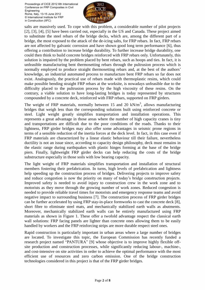
Moreover, mechanically stabilized earth walls can be entirely manufactured using FRP
materials as shown in Figure 1. These offer a twofold advantage respect the classical earth
wall solutions: FRP facing panels are lighter than concrete ones allowing them to be easily
handled by workers and the FRP reinforcing strips are more durable respect steel ones.
Rapid construction is particularly important in urban areas where a large number of bridges
are located. To investigate this topic, the European Commission has recently funded a
research project named “PANTURA” [9] whose objective is to improve highly flexible off-
site production and construction processes, while significantly reducing labour-, machine-,
and cost-intensive on site activities in order to achieve the optimal performance with the most
efficient use of resources and zero carbon emission. One of the bridge construction
technologies considered in this project is that of the FRP girder bridges.
Proceedings of CICE 2012 6th International Conference on FRP Composites in Civil Engineering Rome, Italy, 13-15 June 2012 © International Institute for FRP in Construction (IIFC)
Page 3 of 8
Figure 1. FRP mechanically stabilized earth wall prototype built in one of the facilities of Acciona
Infraestructuras.
2. FRP bridges examples in Spain
2.1 Asturias bridge
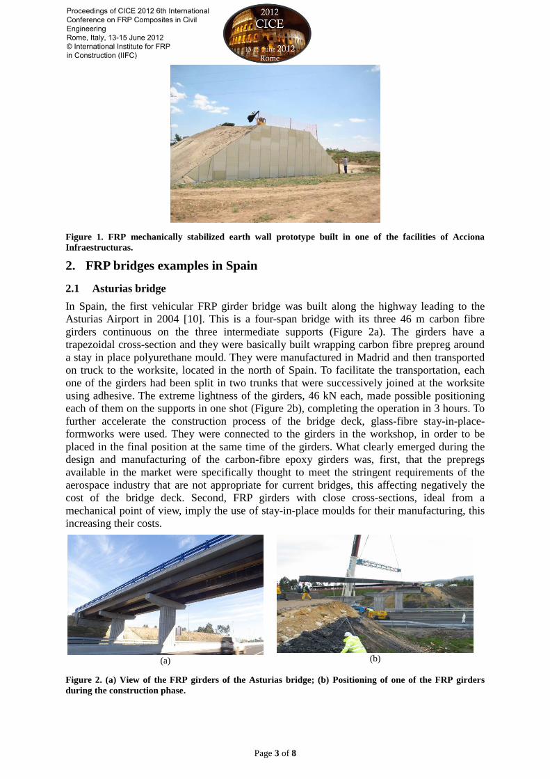
In Spain, the first vehicular FRP girder bridge was built along the highway leading to the
Asturias Airport in 2004 [10]. This is a four-span bridge with its three 46 m carbon fibre
girders continuous on the three intermediate supports (Figure 2a). The girders have a
trapezoidal cross-section and they were basically built wrapping carbon fibre prepreg around
a stay in place polyurethane mould. They were manufactured in Madrid and then transported
on truck to the worksite, located in the north of Spain. To facilitate the transportation, each
one of the girders had been split in two trunks that were successively joined at the worksite
using adhesive. The extreme lightness of the girders, 46 kN each, made possible positioning
each of them on the supports in one shot (Figure 2b), completing the operation in 3 hours. To
further accelerate the construction process of the bridge deck, glass-fibre stay-in-place-
formworks were used. They were connected to the girders in the workshop, in order to be
placed in the final position at the same time of the girders. What clearly emerged during the
design and manufacturing of the carbon-fibre epoxy girders was, first, that the prepregs
available in the market were specifically thought to meet the stringent requirements of the
aerospace industry that are not appropriate for current bridges, this affecting negatively the
cost of the bridge deck. Second, FRP girders with close cross-sections, ideal from a
mechanical point of view, imply the use of stay-in-place moulds for their manufacturing, this
increasing their costs.
(a)
(b)
Figure 2. (a) View of the FRP girders of the Asturias bridge; (b) Positioning of one of the FRP girders
during the construction phase.
Proceedings of CICE 2012 6th International Conference on FRP Composites in Civil Engineering Rome, Italy, 13-15 June 2012 © International Institute for FRP in Construction (IIFC)
Page 4 of 8
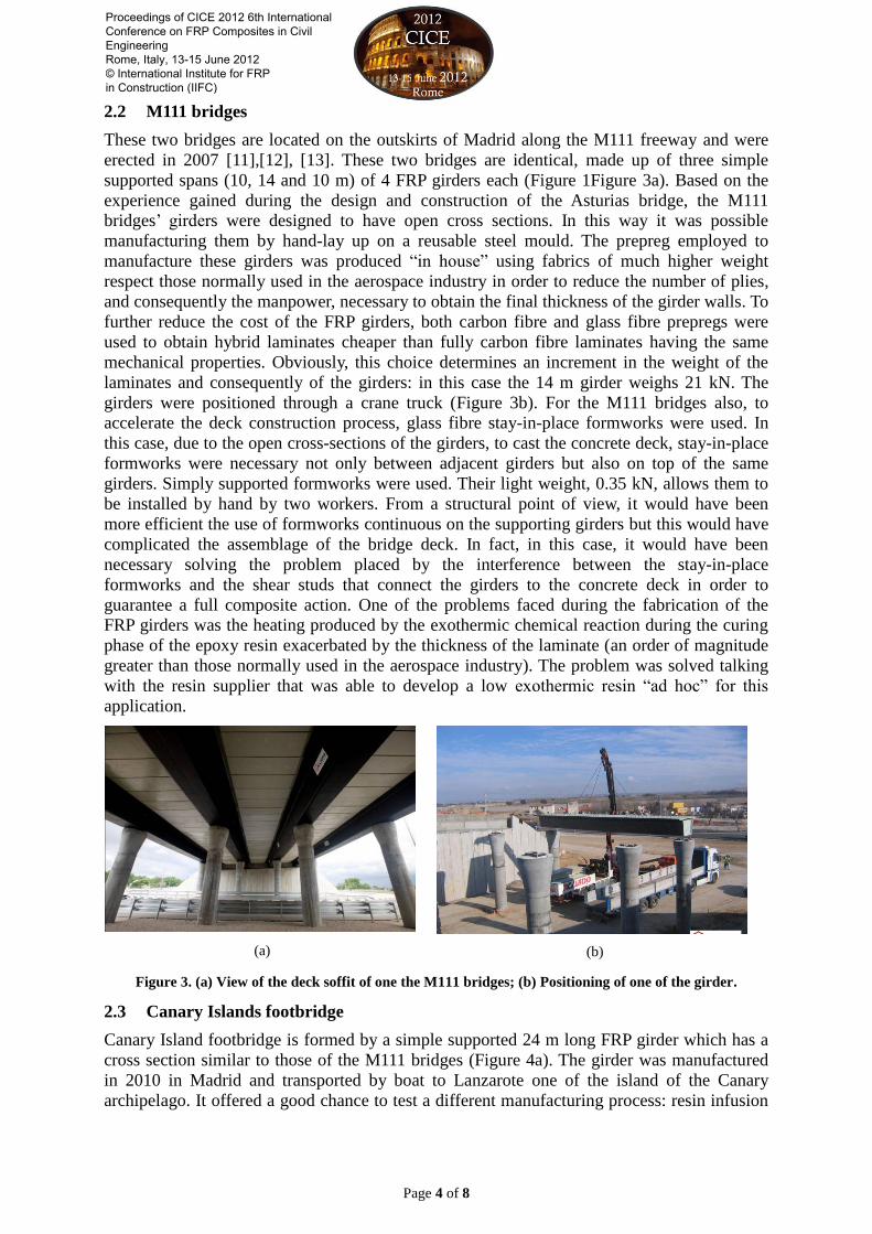
2.2 M111 bridges
These two bridges are located on the outskirts of Madrid along the M111 freeway and were
erected in 2007 [11],[12], [13]. These two bridges are identical, made up of three simple
supported spans (10, 14 and 10 m) of 4 FRP girders each (Figure 1Figure 3a). Based on the
experience gained during the design and construction of the Asturias bridge, the M111
bridges’ girders were designed to have open cross sections. In this way it was possible
manufacturing them by hand-lay up on a reusable steel mould. The prepreg employed to
manufacture these girders was produced “in house” using fabrics of much higher weight
respect those normally used in the aerospace industry in order to reduce the number of plies,
and consequently the manpower, necessary to obtain the final thickness of the girder walls. To
further reduce the cost of the FRP girders, both carbon fibre and glass fibre prepregs were
used to obtain hybrid laminates cheaper than fully carbon fibre laminates having the same
mechanical properties. Obviously, this choice determines an increment in the weight of the
laminates and consequently of the girders: in this case the 14 m girder weighs 21 kN. The
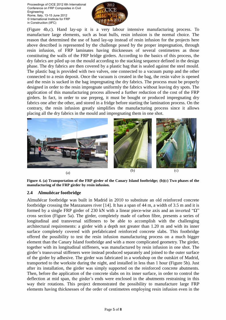
girders were positioned through a crane truck (Figure 3b). For the M111 bridges also, to
accelerate the deck construction process, glass fibre stay-in-place formworks were used. In
this case, due to the open cross-sections of the girders, to cast the concrete deck, stay-in-place
formworks were necessary not only between adjacent girders but also on top of the same
girders. Simply supported formworks were used. Their light weight, 0.35 kN, allows them to
be installed by hand by two workers. From a structural point of view, it would have been
more efficient the use of formworks continuous on the supporting girders but this would have
complicated the assemblage of the bridge deck. In fact, in this case, it would have been
necessary solving the problem placed by the interference between the stay-in-place
formworks and the shear studs that connect the girders to the concrete deck in order to
guarantee a full composite action. One of the problems faced during the fabrication of the
FRP girders was the heating produced by the exothermic chemical reaction during the curing
phase of the epoxy resin exacerbated by the thickness of the laminate (an order of magnitude
greater than those normally used in the aerospace industry). The problem was solved talking
with the resin supplier that was able to develop a low exothermic resin “ad hoc” for this
application.
(a)
(b)
Figure 3. (a) View of the deck soffit of one the M111 bridges; (b) Positioning of one of the girder.
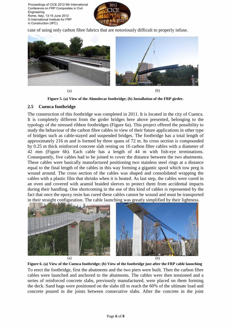
2.3 Canary Islands footbridge
Canary Island footbridge is formed by a simple supported 24 m long FRP girder which has a
cross section similar to those of the M111 bridges (Figure 4a). The girder was manufactured
in 2010 in Madrid and transported by boat to Lanzarote one of the island of the Canary
archipelago. It offered a good chance to test a different manufacturing process: resin infusion
Proceedings of CICE 2012 6th International Conference on FRP Composites in Civil Engineering Rome, Italy, 13-15 June 2012 © International Institute for FRP in Construction (IIFC)
Page 5 of 8
(Figure 4b,c). Hand lay-up it is a very labour intensive manufacturing process. To
manufacture large elements, such as boat hulls, resin infusion is the normal choice. The
reason that determined the use of hand lay-up instead of resin infusion for the projects here
above described is represented by the challenge posed by the proper impregnation, through
resin infusion, of FRP laminates having thicknesses of several centimetres as those
constituting the walls of the FRP bridge girders. According to the basics of this process, the
dry fabrics are piled up on the mould according to the stacking sequence defined in the design
phase. The dry fabrics are then covered by a plastic bag that is sealed against the steel mould.
The plastic bag is provided with two valves, one connected to a vacuum pump and the other
connected to a resin deposit. Once the vacuum is created in the bag, the resin valve is opened
and the resin is sucked in the bag impregnating the dry fabrics. The process must be properly
designed in order to the resin impregnate uniformly the fabrics without leaving dry spots. The
application of this manufacturing process allowed a further reduction of the cost of the FRP
girders. In fact, in order to use prepreg, it must be bought or produced impregnating dry
fabrics one after the other, and stored in a fridge before starting the lamination process. On the
contrary, the resin infusion greatly simplifies the manufacturing process since it allows
placing all the dry fabrics in the mould and impregnating them in one shot.
(a)
(b)
(c)
Figure 4. (a) Transportation of the FRP girder of the Canary Island footbridge; (b)(c) Two phases of the
manufacturing of the FRP girder by resin infusion.
2.4 Almuñécar footbridge
Almuñécar footbridge was built in Madrid in 2010 to substitute an old reinforced concrete
footbridge crossing the Manzanares river [14]. It has a span of 44 m, a width of 3.5 m and it is
formed by a single FRP girder of 230 kN with a linear piece-wise axis and an inverted “Ω”
cross section (Figure 5a). The girder, completely made of carbon fibre, presents a series of
longitudinal and transversal stiffeners to be able to accomplish with the challenging
architectural requirements: a girder with a depth not greater than 1.20 m and with its inner
surface completely covered with prefabricated reinforced concrete slabs. This footbridge
offered the possibility to test the resin infusion manufacturing process on a much bigger
element than the Canary Island footbridge and with a more complicated geometry. The girder,
together with its longitudinal stiffeners, was manufactured by resin infusion in one shot. The
girder’s transversal stiffeners were instead produced separately and joined to the outer surface
of the girder by adhesive. The girder was fabricated in a workshop on the outskirt of Madrid,
transported to the worksite during the night, and installed in less than 1 hour (Figure 5b). Just
after its installation, the girder was simply supported on the reinforced concrete abutments.
Then, before the application of the concrete slabs on its inner surface, in order to control the
deflection at mid span, the girder’s ends were enclosed in the abutments restraining in this
way their rotations. This project demonstrated the possibility to manufacture large FRP
elements having thicknesses of the order of centimetres employing resin infusion even in the
Proceedings of CICE 2012 6th International Conference on FRP Composites in Civil Engineering Rome, Italy, 13-15 June 2012 © International Institute for FRP in Construction (IIFC)
Page 6 of 8
case of using only carbon fibre fabrics that are notoriously difficult to properly infuse.
(a)
(b)
Figure 5. (a) View of the Almuñecar footbridge; (b) Installation of the FRP girder.
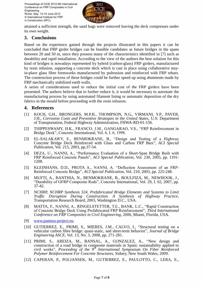
2.5 Cuenca footbridge
The construction of this footbridge was completed in 2011. It is located in the city of Cuenca.
It is completely different from the girder bridges here above presented, belonging to the
typology of the stressed ribbon footbridges (Figure 6a). This project offered the possibility to
study the behaviour of the carbon fibre cables in view of their future applications in other type
of bridges such as cable-stayed and suspended bridges. The footbridge has a total length of
approximately 216 m and is formed by three spans of 72 m. Its cross section is compounded
by 0.25 m thick reinforced concrete slab resting on 16 carbon fibre cables with a diameter of
42 mm (Figure 6b). Each cable has a length of 44 m with fish-eye terminations.
Consequently, five cables had to be joined to cover the distance between the two abutments.
These cables were basically manufactured positioning two stainless steel rings at a distance
equal to the final length of the cables in this way forming a gigantic spool which tow preg is
wound around. The cross section of the cables was shaped and consolidated wrapping the
cables with a plastic film that shrinks when it is heated. As last step, the cables were cured in
an oven and covered with aramid braided sleeves to protect them from accidental impacts
during their handling. One shortcoming in the use of this kind of cables is represented by the
fact that once the epoxy resin has cured these cables cannot be wound and must be transported
in their straight configuration. The cable launching was greatly simplified by their lightness.
(a)
(b)
Figure 6. (a) View of the Cuenca footbridge; (b) View of the footbridge just after the FRP cable launching
To erect the footbridge, first the abutments and the two piers were built. Then the carbon fibre
cables were launched and anchored to the abutments. The cables were then tensioned and a
series of reinforced concrete slabs, previously manufactured, were placed on them forming
the deck. Sand bags were positioned on the slabs till to reach the 60% of the ultimate load and
concrete poured in the joints between consecutive slabs. After the concrete in the joint
Proceedings of CICE 2012 6th International Conference on FRP Composites in Civil Engineering Rome, Italy, 13-15 June 2012 © International Institute for FRP in Construction (IIFC)
Page 7 of 8
attained a sufficient strength, the sand bags were removed leaving the deck compresses under
its own weight.
3. Conclusions
Based on the experience gained through the projects illustrated in this papers it can be
concluded that FRP girder bridges can be feasible candidates as future bridges in the spans
between 20 and 50 m, since they possess many of the characteristics identified in [7] such as
durability and rapid installation. According to the view of the authors the best solution for this
kind of bridges is nowadays represented by hybrid (carbon-glass) FRP girders, manufactured
by resin infusion, supporting a concrete deck which is cast in place using collaborative stay-
in-place glass fibre formworks manufactured by pultrusion and reinforced with FRP rebars.
The construction process of these bridges could be further speed up using abutments made by
FRP mechanically stabilized earth walls.
A series of considerations used to reduce the initial cost of the FRP girders have been
presented. The authors believe that to further reduce it, it would be necessary to automate the
manufacturing process by using automated filament lining or automatic deposition of the dry
fabrics in the mould before proceeding with the resin infusion.
4. References
[1] KOCH, G.H., BRONGERS, M.P.H., THOMPSON, N.G., VIRMANI, Y.P., PAYER, J.H., Corrosion Costs and Preventive Strategies in the United States, U.S: Department of Transportation, Federal Highway Administration, FHWA-RD-01-156.
[2] THIPPESWAMY, H.K., FRANCO, J.M., GANGARAO, V.S., “FRP Reinforcement in Bridge Deck”, Concrete International, Vol. 6, I. 6, 1998.
[3] EL-SALAKAWY, E., BENMOKRANE, B., “Design and Testing of a Highway Concrete Bridge Deck Reinforced with Glass and Carbon FRP Bars”, ACI Special Publication, Vol. 215, 2003, pp.37-54.
[4] DEZA, U., NANNI, A., “Performance Evaluation of a Short-Span Bridge Built with FRP Reinforced Concrete Panels”, ACI Special Publication, Vol. 230, 2005, pp. 1191-1208.
[5] KLEINHANS, D.D., PROTA A., NANNI, A. “Deflection Assessment of an FRP-Reinforced Concrete Bridge”, ACI Special Publication, Vol. 210, 2003, pp. 225-248.
[6] MUFTI, A., BANTHIA, N., BENMOKRANE, B., BOULFIZA, M., NEWHOOK, J., “Durability of GFRP Composite Rods”, Concrete International, Vol. 29, I. 02, 2007, pp. 37-42.
[7] NCHRP, NCHRP Synthesis 324. Prefabricated Bridge Elements and Systems to Limit Traffic Disruption During Construction. A Synthesis of Highway Practice, Transportation Research Board, 2003, Washington D.C., USA.
[8] MATTA, F., NANNI, A., RINGELSTETTER, T.E., BANK, L.C., “Rapid Construction of Concrete Bridge Deck Using Prefabricated FRP Reinforcement”, Third International Conference on FRP Composites in Civil Engineering, 2006, Miami, Florida, USA.
[9] www.pantura-project.eu.
[10] GUTIERREZ, E., PRIMI, S., MIERES, J.M., CALVO, I., “Structural testing on a vehicular carbon fibre bridge: quasi-static, and short-term behavior”, Journal of Bridge Engineering ASCE, Vol. 13, No. 3, 2008, pp. 271-281.
[11] PRIMI, S., AREIZA, M., BANSAL, A., GONZALEZ, A., “New design and construction of a road bridge in composite materials in Spain: sustainability applied to civil works”, Proceeding of the 9
th International Symposium On Fiber Reinforced
Polymer Reinforcement For Concrete Structures, Sidney, New South Wales, 2009.
[12] CAPERAN, P., POLJANSEK, M., GUTIERREZ, E., PAULOTTO, C., LERA, E.,
Proceedings of CICE 2012 6th International Conference on FRP Composites in Civil Engineering Rome, Italy, 13-15 June 2012 © International Institute for FRP in Construction (IIFC)

Page 8 of 8
“Experimental campaign on a full scale motorway bridge”, Proceeding of the Conference on Advanced Composite in Constructions, 2011, Worwick,UK.
[13] CAPERAN, P., POLJANSEK, M., GUTIERREZ, E., PRIMI, S., PAULOTTO, C., “Optical 3D Measuraments ona FRP Beam Tested at Serviceability Limit”, Composite Structures, In Press.
[14] PRIMI, S., CALVO HERRERA, I., PAULOTTO C., AREIZA HURTADO, M., LLAGO ACERO R., “Diseño y fabricación de una pasarela en fibra de carbono sobre el rio Manzanares”, V Congreso ACHE, Barcelona, 2011. (In Spanish).
Proceedings of CICE 2012 6th International Conference on FRP Composites in Civil Engineering Rome, Italy, 13-15 June 2012 © International Institute for FRP in Construction (IIFC)


![USS Box Girder Bridges a Construction Manual[1]](https://img.pdfslide.net/doc/110x75/552720ee4979598a178b4583/uss-box-girder-bridges-a-construction-manual1.jpg)